EP3705369A1 - Procédé de détection d'anomalie de matériel roulant exploitant un signal de déformation d'un support de rail - Google Patents
Procédé de détection d'anomalie de matériel roulant exploitant un signal de déformation d'un support de rail Download PDFInfo
- Publication number
- EP3705369A1 EP3705369A1 EP20158549.4A EP20158549A EP3705369A1 EP 3705369 A1 EP3705369 A1 EP 3705369A1 EP 20158549 A EP20158549 A EP 20158549A EP 3705369 A1 EP3705369 A1 EP 3705369A1
- Authority
- EP
- European Patent Office
- Prior art keywords
- signal
- anomaly
- residue
- type
- decomposition
- Prior art date
- Legal status (The legal status is an assumption and is not a legal conclusion. Google has not performed a legal analysis and makes no representation as to the accuracy of the status listed.)
- Granted
Links
Images




Classifications
-
- B—PERFORMING OPERATIONS; TRANSPORTING
- B61—RAILWAYS
- B61L—GUIDING RAILWAY TRAFFIC; ENSURING THE SAFETY OF RAILWAY TRAFFIC
- B61L1/00—Devices along the route controlled by interaction with the vehicle or train
- B61L1/02—Electric devices associated with track, e.g. rail contacts
- B61L1/06—Electric devices associated with track, e.g. rail contacts actuated by deformation of rail; actuated by vibration in rail
-
- G—PHYSICS
- G01—MEASURING; TESTING
- G01L—MEASURING FORCE, STRESS, TORQUE, WORK, MECHANICAL POWER, MECHANICAL EFFICIENCY, OR FLUID PRESSURE
- G01L1/00—Measuring force or stress, in general
- G01L1/25—Measuring force or stress, in general using wave or particle radiation, e.g. X-rays, microwaves, neutrons
-
- B—PERFORMING OPERATIONS; TRANSPORTING
- B61—RAILWAYS
- B61L—GUIDING RAILWAY TRAFFIC; ENSURING THE SAFETY OF RAILWAY TRAFFIC
- B61L23/00—Control, warning or like safety means along the route or between vehicles or trains
- B61L23/04—Control, warning or like safety means along the route or between vehicles or trains for monitoring the mechanical state of the route
- B61L23/042—Track changes detection
- B61L23/045—Rail wear
-
- G—PHYSICS
- G01—MEASURING; TESTING
- G01L—MEASURING FORCE, STRESS, TORQUE, WORK, MECHANICAL POWER, MECHANICAL EFFICIENCY, OR FLUID PRESSURE
- G01L5/00—Apparatus for, or methods of, measuring force, work, mechanical power, or torque, specially adapted for specific purposes
- G01L5/0047—Apparatus for, or methods of, measuring force, work, mechanical power, or torque, specially adapted for specific purposes measuring forces due to residual stresses
-
- B—PERFORMING OPERATIONS; TRANSPORTING
- B61—RAILWAYS
- B61L—GUIDING RAILWAY TRAFFIC; ENSURING THE SAFETY OF RAILWAY TRAFFIC
- B61L27/00—Central railway traffic control systems; Trackside control; Communication systems specially adapted therefor
- B61L27/50—Trackside diagnosis or maintenance, e.g. software upgrades
Definitions
- the field of the invention is that of monitoring the state of health of rolling stock on railway tracks, in particular a train, a metro or a tram.
- the invention aims more particularly at detecting anomalies in such materials from measurements of deformation of the supports of the rails.
- Rail track supports are objects placed under the rails in order to provide them with a support adapted to the stresses to which the rails are subjected and to maintain their spacing while distributing the loads on the base of these supports, for example example of ballast or a concrete slab.
- These supports can be sleepers or alternatively supports for switches and crossings at the level of the switches.
- these supports can be instrumented with accelerometers to make it possible to detect flat areas on train wheels (such wheels being designated by the term square wheels in what follows). This detection is performed by means of a discrete wavelet transform of the signals supplied by the accelerometers. The coefficients of the two highest levels of the wavelet decomposition are exploited to detect the passage of the axles opposite an accelerometer and from there to deduce the speed of the train and to construct a mask used during the detection of square wheels to minimize the false alarms.
- This detection is carried out by comparing the coefficients of a low level of the decomposition into wavelets, not masked, with a threshold.
- This method turns out to be relatively complex due to the use of masking and is based on an acceleration measurement linked to the rail-wheel contact force which is difficult to model and therefore to analyze.
- the rail supports can also be instrumented, for example by integrating Bragg grating optical fiber sensors as described in the patent. FR 2 983 812 B1 , to measure micro-deformations and thus evaluate the stresses to which they are subjected, in particular during the passage of rolling stock. These measurements can thus be used to detect abnormal constraints linked to the passage of defective rolling stock, and thus to detect an anomaly in rolling stock.
- One method for this purpose consists in calculating the difference between the maximum value and the minimum value of a sequence of samples of a signal of deformation of a sleeper during the passage of a train over this sleeper. This method, although particularly simple, only makes it possible to find the most obvious anomalies.
- a statistical approach can also be used to look for outliers in measurements. Such an approach works well in general for passenger trains with well distributed axle load. But this approach is easily faulted for trains which have very irregular load distributions, for example freight trains.
- the invention aims to provide a more robust technique for detecting anomaly in rolling stock by means of a signal for measuring the deformation of a support for railway tracks.
- the invention provides for this a method implemented by computer for detecting an anomaly in rolling stock on railway tracks which rest on a rail support.
- This method comprises a decomposition by discrete wavelet transform of a measurement signal delivered by a deformation sensor of the rail support into an approximation signal and a series of detail signals.
- a residue signal is formed by the sum of all or part of the detail signals and the method includes searching for outliers in the residue signal to detect a rolling stock anomaly.
- a computer-implemented method of detecting an anomaly in rolling stock on railway tracks that rest on a rail support uses a measurement signal delivered by a sensor capable of measuring the deformation of a support for railway tracks.
- the sensor can be attached to the surface of the support or be integrated within the support.
- figure 1 a recording of about thirty seconds of the measurement signal delivered by such a sensor during which a train passes over the support.
- This recording carries a transient T induced by a train anomaly.
- the figure 2 is a zoom of the signal from the figure 1 around this transient T.
- This recording can be the subject of a pre-processing comprising a shift and possibly a normalization.
- the method according to the invention comprises, with reference to the figure 9 , a DECOMP step consisting, where appropriate after the aforementioned pre-processing, in breaking down, by discrete wavelet transform, the measurement signal S delivered by the deformation sensor into an approximation signal A J and a residue signal R J.
- This decomposition is carried out up to a decomposition level J according to the following conventional procedure.
- the measurement signal S is broken down into an approximation signal A 1 which provides a smoothed view of the original signal and into a detail signal D 1 amplifying the high frequency components of the signal.
- the approximation signal A 1 is in turn broken down into an approximation signal A 2 and into a detail signal D 2 (which therefore appears as a corrective term between the two successive approximations A 1 and A 2 ). This procedure is repeated until the desired level of decomposition is obtained J.
- an approximation signal A J is obtained and a series of detail signals D 1 , D 2 , ..., D J and the signal S is obtained.
- decompose according to S A J + ⁇ j ⁇ J D j .
- a signal of residue R J is formed with the sum of all or part of the detail signals.
- the functions ⁇ j, k are localized in time: only part of the samples is non-zero.
- the choice of the wavelet is guided by the shape of the signal S to be decomposed, by typically selecting a wavelet resembling this signal. In the examples presented below, this choice fell on the Symlet 5 wavelet.
- the method according to the invention comprises a preliminary step of determining a level of decomposition of the decomposition by discrete wavelet transform of the measurement signal, said level of decomposition minimizing the quadratic error w ( ⁇ v, R - ⁇ v, S ) 2 + ( ⁇ R - ⁇ v, S ) 2 , where w is a weighting parameter, ⁇ v, R is the standard deviation of the noise contained in the residual signal, ⁇ v, S is the standard deviation of the noise contained in the measurement signal S and ⁇ R is the standard deviation of the residual signal.
- the invention is not exclusive of this example of the choice of the level of decomposition, the latter being able to be carried out according to other methods such as for example methods based on the energy contained in the detail signals.
- the measurement signal S and the approximation signal A 3 and on the lower portion of the same figure 3 the residue signal R 3 .
- the figure 4 is a zoom of the figure 3 around the transient T characteristic of the anomaly.
- the standard deviation of the noise affecting the measurement signal ⁇ v, S is estimated at 1.08592 over the first 3 seconds of the signal.
- a thresholding of the coefficients of the decomposition (for example a soft thresholding called “soft coefficient thresholding”) can be implemented in order to reduce the noise level in the reconstruction and to obtain a residue signal not containing ideally than the transients characteristic of any anomalies.
- the method according to the invention comprises a RECH-PA step of searching for aberrant points in the residue signal to detect an anomaly of the rolling stock.
- These aberrant points PA appear as solid circles on the figures 3 and 4 . They correspond to points which “come out” of the noise.
- the detection of an anomaly takes place for a succession of aberrant points, for example over a time window following an aberrant point whose size is variable according to the speed of the rolling stock.
- the search for aberrant points in the residue signal can in particular consist in searching for the points of the residue signal whose absolute value of the amplitude
- a detected anomaly is the subject of a CLAS classification, for example as a first type of anomaly or a second type of anomaly, by means of an analysis of the residue signal.
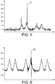
- the first type of anomaly is for example an axle overload which, as shown in figure 5 , causes a transient Tps of the residue signal in the form of a single peak.
- the second type of anomaly is for example a square wheel which, as shown in figure 6 , causes an abrupt alternation-type residual signal Tpd transient around the “M” axle peak curve in the form of at least two single peaks of opposite signs. Therefore, the detected anomaly can be classified as an anomaly of the first type when it is associated with a single peak of the residue signal and can be classified as an anomaly of the second type when it is associated with at least two single peaks of opposite signs. .
- the analysis of the residue signal to achieve this classification can exploit the aberrant points previously detected to differentiate the different types of anomaly.
- the anomaly detected is classified as an anomaly of the second type when it is associated with aberrant points, one of which has an amplitude less than a first negative threshold and another of which has an amplitude greater than a second positive threshold.
- the anomaly is then classified as characteristic of a square wheel if the minimum of the outliers of the anomaly is less than -s d and if the maximum of the outliers of the anomaly is greater than sd. Otherwise, the anomaly is classified as characteristic of an axle overload.
- the method can further comprise a dating of a detected anomaly, for example according to the instant of the maximum in absolute value of the outliers of the anomaly, according to the instant of the median in absolute value of the outliers of the anomaly or again according to the instant of the first aberrant point of the anomaly.
- the method may also include determining a severity of a detected anomaly. For example, for an anomaly of the axle overload type, this severity may correspond to the maximum of the outliers of the anomaly. For a square wheel type anomaly, this severity may for example correspond to the largest amplitude deviation y (cf. figure 7 ) between outliers of the anomaly.
- a supervised classification algorithm can be trained and used to efficiently recognize different types of anomalies.
- the detection of the transit of the axles on the support and its deformation sensor is generally based on peak detection algorithms which look for rapid variations in the measurement signal S of deformation.
- the choice of adjustment parameters makes it possible to make these algorithms less sensitive to noise, for example by fixing a minimum distance between two axle peaks or by fixing a minimum variation in deformation.
- this detection is not robust to the anomalies contained in the signal since these are transient phenomena which also vary rapidly.
- the reconstruction of the approximation signal A J provides a signal cleaned of the measurement noise and of the anomalies detected, on which it is possible to perform the detection of axle peaks.
- the method also comprises a RECH-Ep step of detecting peaks in the approximation signal.
- the figure 8 illustrates in this regard the result of the detection of EP axle peaks in the area of the anomaly taken as an example above. This robust detection of axle peaks notably enables automatic recognition of rolling stock. Indeed, locomotives and wagons have known and listed characteristics, in particular the length of the coaches and the location of the bogies which make it possible to calculate the distances between axles.
- train speed can easily be determined by time shifting strain measurements.
- approximation signal at low noise or anomaly level, it is possible to avoid falsifying the evaluation of the distances between axles and deteriorating the automatic recognition of the material.
- the invention is not limited to the method described above, but also extends to a data processing system configured to implement this as well as to a computer program product comprising instructions which, when the program is executed by a computer, lead it to implement this process.
Landscapes
- Engineering & Computer Science (AREA)
- Physics & Mathematics (AREA)
- General Physics & Mathematics (AREA)
- Mechanical Engineering (AREA)
- Health & Medical Sciences (AREA)
- Toxicology (AREA)
- Automation & Control Theory (AREA)
- Train Traffic Observation, Control, And Security (AREA)
- Testing Of Devices, Machine Parts, Or Other Structures Thereof (AREA)
Abstract
Description
- Le domaine de l'invention est celui du suivi de l'état de santé d'un matériel roulant sur des rails de voie ferrée, notamment un train, un métro ou un tramway. L'invention vise plus particulièrement à détecter des anomalies de tels matériels à partir de mesures de déformation des supports des rails.
- Les supports de rails pour voie ferrée sont des objets placés sous les rails afin de fournir à ceux-ci un support adapté aux contraintes auxquelles les rails sont soumis et à maintenir leur écartement tout en répartissant les charges sur l'assise de ces supports, par exemple du ballast ou une dalle en béton. Ces supports peuvent être des traverses ou encore des supports pour appareil de voie au niveau des aiguillages.
- Comme décrit dans l'article de V. Belotti et al. intitulé "Wheel-flat diagnostic tool via wavelet transform," Mech. Syst. Signal Process., vol. 20, no. 8, pp. 1953-1966, Nov. 2006, ces supports peuvent être instrumentés avec des accéléromètres pour permettre de détecter des zones plates sur des roues de trains (de telles roues étant désignées par le terme de roues carrées dans ce qui suit). Cette détection est réalisée au moyen d'une transformée en ondelettes discrète des signaux fournis par les accéléromètres. Les coefficients des deux plus hauts niveaux de la décomposition en ondelettes sont exploités pour détecter le passage des essieux en regard d'un accéléromètre et de là en déduire la vitesse du train et construire un masque utilisé lors de la détection de roue carrée pour minimiser les fausses alarmes. Cette détection est réalisée par comparaison des coefficients d'un bas niveau de la décomposition en ondelettes, non masqués, avec un seuil. Cette méthode s'avère relativement complexe du fait du recours au masquage et repose sur une mesure d'accélération liée à la force de contact rail-roue qui est difficile à modéliser et donc à analyser.
- Les supports de rails peuvent également être instrumentés, par exemple en y intégrant des capteurs en fibre optique à réseau de Bragg comme décrit dans le brevet
FR 2 983 812 B1 - Une méthode à cet effet consiste à calculer la différence entre la valeur maximale et la valeur minimale d'une séquence d'échantillons d'un signal de déformation d'une traverse lors du passage d'un train sur cette traverse. Cette méthode, bien que particulièrement simple, ne permet que de trouver les anomalies les plus flagrantes.
- Une approche statistique peut aussi être utilisée pour rechercher des valeurs aberrantes dans les mesures. Une telle approche fonctionne bien en général pour les trains de passagers dont la charge par essieu est bien répartie. Mais cette approche est facilement mise en défaut pour des trains qui présentent des distributions de charges très irrégulières, par exemple des trains de marchandise.
- L'invention vise à fournir une technique plus robuste de détection d'anomalie d'un matériel roulant au moyen d'un signal de mesure de déformation d'un support de rails de voie ferrée.
- L'invention propose pour cela un procédé mis en œuvre par ordinateur de détection d'une anomalie d'un matériel roulant sur des rails de voie ferrée qui reposent sur un support de rails. Ce procédé comprend une décomposition par transformée en ondelettes discrète d'un signal de mesure délivré par un capteur de déformation du support de rails en un signal d'approximation et une série de signaux de détail. Un signal de résidu est formé par la somme de tout ou partie des signaux de détail et le procédé comprend une recherche de points aberrants dans le signal de résidu pour détecter une anomalie du matériel roulant.
- Certains aspects préférés mais non limitatifs de ce procédé sont les suivants :
- la recherche de points aberrants dans le signal de résidu consiste à rechercher les points du signal de résidu dont la valeur absolue de l'amplitude |ri | satisfait |ri | > µv,R + ασv,R , où µv,R est la moyenne du bruit contenu dans le signal de résidu, σv,R est l'écart-type du bruit contenu dans le signal de résidu et α est un paramètre de réglage d'une sensibilité de détection ;
- il comprend en outre une étape préalable de détermination d'un niveau de décomposition de la décomposition par transformée en ondelettes discrète du signal de mesure, ledit niveau de décomposition minimisant une erreur quadratique donnée par w(σv,R - σv,S )2 + (σR - σv,S )2, où w est un paramètre de pondération, σv,R est l'écart-type du bruit contenu dans le signal de détails, σv,S est l'écart-type du bruit contenu dans le signal de mesure et σR est l'écart-type du signal de détails ;
- il comprend en outre en cas de détection d'une anomalie du matériel roulant une classification de l'anomalie détectée en un premier type d'anomalie ou un deuxième type d'anomalie ;
- l'anomalie détectée est classifiée comme anomalie du premier type lorsqu'elle est associée à un pic simple du signal de résidu et est classifiée comme anomalie du second type lorsqu'elle est associée à au moins deux pics simples du signal de résidu de signes opposés ;
- l'anomalie détectée est classifiée comme anomalie du second type lorsqu'elle est associée à des points aberrants dont un présente une amplitude inférieure à un premier seuil négatif et dont un autre présente une amplitude supérieure à un second seuil positif;
- il comprend en outre une étape de détermination d'une gravité d'une anomalie détectée ;
- il comprend en outre une étape de détection de pics dans le signal d'approximation.
- D'autres aspects, buts, avantages et caractéristiques de l'invention apparaîtront mieux à la lecture de la description détaillée suivante de formes de réalisation préférées de celle-ci, donnée à titre d'exemple non limitatif, et faite en référence aux dessins annexés sur lesquels :
- [
Fig. 1 ] représente un exemple de signal de mesure délivré par un capteur de déformation d'un support de rails, ce signal étant porteur d'un transitoire induit par une anomalie de matériel roulant ; - [
Fig. 2 ] est un zoom du signal de lafigure 1 autour du transitoire caractéristique de l'anomalie ; - [
Fig. 3 ] représente en haut le signal de mesure et le signal d'approximation et en bas le signal de résidu dans lequel des points aberrants ont été détectés ; - [
Fig. 4 ] est un zoom de lafigure 3 autour du transitoire caractéristique de l'anomalie ; - [
Fig. 5 ] représente un signal de résidu porteur d'un pic simple caractéristique d'une anomalie de type surcharge d'essieu ; - [
Fig. 6 ] représente un signal de résidu porteur de deux pics simples de signes opposés caractéristiques d'une anomalie de type roue carrée ; - [
Fig. 7 ] illustre un mode de réalisation possible de la détection d'une anomalie de type roue carrée ; - [
Fig. 8 ] représente un signal de mesure et son signal d'approximation à partir duquel des pics d'essieux sont détectés ; - [
Fig. 9 ] est un ordinogramme d'un procédé conforme à l'invention. - L'invention porte sur un procédé mis en œuvre par ordinateur de détection d'une anomalie d'un matériel roulant sur des rails de voie ferrée qui reposent sur un support de rails. L'invention exploite un signal de mesure délivré par un capteur apte à mesurer la déformation d'un support de rails de voie ferrée. Le capteur peut être accolé à la surface du support ou être intégré au sein du support.
- Dans ce qui suit, on prend l'exemple d'un capteur de déformation de type fibre optique à réseau de Bragg dont le signal de mesure est par exemple échantillonné à 500 ou 1000 Hz. On a ainsi représenté sur la
figure 1 un enregistrement d'une trentaine de secondes du signal de mesure délivré par un tel capteur au cours duquel un train passe sur le support. Cet enregistrement est porteur d'un transitoire T induit par une anomalie du train. Lafigure 2 est un zoom du signal de lafigure 1 autour de ce transitoire T. On y reconnait notamment la forme caractéristique en « M » des pics liés au passage des essieux des locomotives et des wagons sur le support équipé du capteur Cet enregistrement peut faire l'objet d'un prétraitement comportant une compensation de décalage et éventuellement une normalisation. - Afin de détecter un transitoire caractéristique d'une anomalie de matériel roulant, le procédé selon l'invention comporte, en référence à la
figure 9 , une étape DECOMP consistant, le cas échéant après le prétraitement susmentionné, à décomposer, par transformée en ondelettes discrète, le signal de mesure S délivré par le capteur de déformation en un signal d'approximation AJ et un signal de résidu RJ. Cette décomposition est réalisée jusqu'à un niveau de décomposition J selon la procédure conventionnelle suivante. Le signal de mesure S est décomposé en un signal d'approximation A1 qui propose une vision lissée du signal d'origine et en un signal de détail D1 amplifiant les composantes hautes fréquences du signal. Le signal d'approximation A1 est à son tour décomposé en un signal d'approximation A2 et en un signal de détail D2 (qui apparaît donc comme un terme correctif entre les deux approximations successives A1 et A2). Cette procédure est répétée jusqu'à obtenir le niveau de décomposition souhaité J. On obtient au final un signal d'approximation AJ et une série de signaux de détail D1, D2, ..., DJ et le signal S se décompose ainsi selon S = AJ + ∑ j≤J Dj. On forme un signal de résidu RJ avec la somme de tout ou partie des signaux de détail. Ainsi le signal de résidu peut consister en la somme complète de 1 à J des signaux de détails, mais peut aussi se constituer d'un choix de signaux de détails particuliers (par exemple pour J = 3, R3 = D1+D3, D2 non inclus). - La décomposition du signal S produit plus précisément un ensemble de coefficients notés cAj et cDj (1 ≤ j ≤ J) pour approximation et détails respectivement. A partir de ces coefficients, on peut reconstruire le signal S au niveau souhaité, afin d'une part d'en obtenir l'approximation AJ (contenu basses fréquences) et la somme des signaux de détail ∑ j≤ J Dj (contenu hautes fréquences) tels que le signal S se décompose selon S = AJ + ∑ j≤J Dj, avec la relation A J-1 = AJ + DJ entre deux approximations successives et

- Contrairement aux fonctions sinus et cosinus utilisées dans la transformée de Fourier, les fonctions ψj,k sont localisée temporellement : seulement une partie des échantillons est non nulle. En choisissant le niveau de décomposition de manière adéquate, on peut séparer le signal de micro déformations (i.e. les pics d'essieux) du bruit de mesure et des anomalies du matériel roulant qui se caractérisent par des phénomènes transitoires brusques localisés temporellement.
- Le choix de l'ondelette est guidé par la forme du signal S à décomposer, en sélectionnant typiquement une ondelette ressemblante à ce signal. Dans les exemples exposés ci-après, ce choix s'est porté sur l'ondelette Symlet 5.
- Le choix J du niveau de décomposition est réalisé de manière à assurer le meilleur compromis de séparation. Dans un mode de réalisation possible, le procédé selon l'invention comprend une étape préalable de détermination d'un niveau de décomposition de la décomposition par transformée en ondelettes discrète du signal de mesure, ledit niveau de décomposition minimisant l'erreur quadratique w(σv,R - σv,S )2 + (σR - σv,S )2, où w est un paramètre de pondération, σv,R est l'écart-type du bruit contenu dans le signal de résidu, σv,S est l'écart-type du bruit contenu dans le signal de mesure S et σR est l'écart-type du signal de résidu.
- En effet, une bonne séparation implique :
- d'une part, que l'écart-type du bruit contenu dans le signal de résidu σv,R et l'écart-type du bruit dans le signal de mesure σv,S soient les plus proches possible, i.e. σv,R ≈ σv,S ; et
- d'autre part, que l'écart-type du signal de résidu σR reste proche de l'écart-type du bruit dans le signal de mesure σv,S , en général légèrement supérieur car il peut subsister une contribution des pics d'essieux et du fait de la présence d'une anomalie, i.e. σR ≳ σv,S .
- En procédant de la sorte, on assure que les signaux de détail ne contiennent principalement que le bruit et les transitoires dus à la présence d'une anomalie.
- L'invention n'est pas exclusive de cet exemple du choix du niveau de décomposition, ce dernier pouvant être réalisé selon d'autres méthodes telles que par exemple des méthodes basées sur l'énergie contenue dans les signaux de détail.
- L'écart-type du bruit contenu dans le signal de mesure σv,S peut être facilement estimé sur la partie du signal enregistrée avant le passage du train, par exemple sur les n premières secondes sur l'exemple de la
figure 1 (avec par exemple n=3 secondes). - Dans un exemple de réalisation exploitant l'ondelette Symlet 5, le niveau de décomposition choisi est J=3. On a représenté dans la portion supérieure de la
figure 3 le signal de mesure S et le signal d'approximation A3 et sur la portion inférieure de cette mêmefigure 3 le signal de résidu R3. Lafigure 4 est un zoom de lafigure 3 autour du transitoire T caractéristique de l'anomalie. L'écart-type du bruit affectant le signal de mesure σv,S est estimé à 1.08592 sur les 3 premières secondes du signal. Le niveau de décomposition J=3 donne un écart-type du bruit contenu dans le signal de résidu σv,R égal à 1.03472 et un écart-type des résidus σR égal à 1.20381. - Dans un mode de réalisation possible, un seuillage des coefficients de la décomposition (par exemple un seuillage doux dit « soft coefficient thresholding ») peut être mis en œuvre afin de réduire le niveau de bruit dans la reconstruction et obtenir un signal de résidu ne contenant idéalement que les transitoires caractéristiques d'éventuelles anomalies.
- Suite à la décomposition DECOMP du signal de mesure en un signal d'approximation et un signal de résidu, le procédé selon l'invention comprend une étape RECH-PA de recherche de points aberrants dans le signal de résidu pour détecter une anomalie du matériel roulant. Ces points aberrants PA apparaissent sous la forme de cercles pleins sur les
figures 3 et 4 . Ils correspondent à des points qui « sortent » du bruit. La détection d'une anomalie s'opère pour une succession de points aberrants, par exemple sur une fenêtre temporelle suivant un point aberrant dont la taille est variable selon la vitesse du matériel roulant. - La recherche de points aberrants dans le signal de résidu peut notamment consister à rechercher les points du signal de résidu dont la valeur absolue de l'amplitude |ri | satisfait |ri | > µv,R + ασv,R , où µv,R est la moyenne du bruit contenu dans le de résidu pendant les n premières secondes (i.e. avant passage du train), σv,R est l'écart-type du bruit contenu dans le signal de résidu et α est un paramètre de réglage d'une sensibilité de détection. La moyenne µv,R est généralement sensiblement nulle du fait de la compensation du décalage réalisée lors du prétraitement. On choisit par exemple a=8.
- Dans un mode de réalisation possible, une anomalie détectée fait l'objet d'une classification CLAS, par exemple en un premier type d'anomalie ou un deuxième type d'anomalie, au moyen d'une analyse du signal de résidu. Le premier type d'anomalie est par exemple une surcharge d'essieu qui, comme représenté en
figure 5 , provoque un transitoire Tps du signal de résidu présentant la forme d'un pic simple. Le deuxième type d'anomalie est par exemple une roue carrée qui, comme représenté enfigure 6 , provoque un transitoire Tpd du signal de résidu de type alternance brusque autour de la courbe de pic d'essieu en « M » présentant la forme d'au moins deux pics simples de signes opposés. Dès lors, l'anomalie détectée peut être classifiée comme anomalie du premier type lorsqu'elle est associée à un pic simple du signal de résidu et peut classifiée comme anomalie du second type lorsqu'elle est associée à au moins deux pics simples de signes opposés. - L'analyse du signal de résidu pour réaliser cette classification peut exploiter les points aberrants préalablement détectés pour différencier les différents types d'anomalie. Par exemple, l'anomalie détectée est classifiée comme anomalie du second type lorsqu'elle est associée à des points aberrants dont un présente une amplitude inférieure à un premier seuil négatif et dont un autre présente une amplitude supérieure à un second seuil positif. Comme représenté en
figure 7 , on peut choisir des seuils symétriques sd et -sd. L'anomalie est alors classifiée comme caractéristique d'une roue carrée si le minimum des points aberrants de l'anomalie est inférieur à -sd et si le maximum des points aberrants de l'anomalie est supérieur à sd. Dans le cas contraire, l'anomalie est classifiée comme caractéristique d'une surcharge d'essieu. - Le procédé peut en outre comprendre une datation d'une anomalie détectée, par exemple selon l'instant du maximum en valeur absolue des points aberrants de l'anomalie, selon l'instant de la médiane en valeur absolue des points aberrants de l'anomalie ou encore selon l'instant du premier point aberrant de l'anomalie.
- Le procédé peut également comprendre la détermination d'une gravité d'une anomalie détectée. Par exemple, pour une anomalie de type surcharge d'essieu, cette gravité peut correspondre au maximum des points aberrants de l'anomalie. Pour une anomalie de type roue carrée, cette gravité peut par exemple correspondre au plus grand écart d'amplitude y (cf.
figure 7 ) entre points aberrants de l'anomalie. - On relèvera qu'en disposant d'une base de données annotée de cas d'anomalies, un algorithme de classification supervisée peut être entrainé et utilisé pour reconnaître efficacement différents types d'anomalies.
- La détection du transit des essieux sur le support et son capteur de déformation se base généralement sur des algorithmes de détection de pics qui recherchent des variations rapides dans le signal de mesure S de déformation. Le choix de paramètres de réglage permet de rendre ces algorithmes moins sensibles au bruit, par exemple en fixant une distance minimale entre deux pics d'essieu ou en fixant une variation minimale en déformation. Toutefois, cette détection n'est pas robuste aux anomalies contenues dans le signal puisque ce sont des phénomènes transitoires qui sont également à variation rapide.
- Dans le cadre de l'invention, la reconstruction du signal d'approximation AJ fournit un signal nettoyé du bruit de mesure et des anomalies détectées, sur lequel il est possible d'effectuer la détection des pics d'essieux. Ainsi, dans un mode de réalisation possible de l'invention, le procédé comprend également une étape RECH-Ep de détection de pics dans le signal d'approximation. La
figure 8 illustre à cet égard le résultat de la détection des pics d'essieux EP dans la zone de l'anomalie prise en exemple précédemment. Cette détection robuste des pics d'essieu permet notamment la reconnaissance automatique du matériel roulant. En effet les locomotives et wagons possèdent des caractéristiques connues et répertoriées, notamment la longueur des voitures et l'emplacement des bogies qui permettent de calculer les distances entre essieux. Si l'on dispose de deux capteurs de déformation séparés d'une distance connue, la vitesse du train peut facilement être déterminée par décalage temporel des mesures de déformation. En exploitant le signal d'approximation à faible niveau de bruit ou d'anomalies, on évite de fausser l'évaluation des distances entre essieux et de détériorer la reconnaissance automatique du matériel. - L'invention n'est pas limitée au procédé précédemment décrit, mais s'étend également un système de traitement de données configuré pour mettre en œuvre ce ainsi qu'à un produit programme d'ordinateur comprenant des instructions qui, lorsque le programme est exécuté par un ordinateur, conduisent celui-ci à mettre en œuvre ce procédé.
Claims (10)
- Procédé mis en œuvre par ordinateur de détection d'une anomalie d'un matériel roulant sur des rails de voie ferrée qui reposent sur un support de rails, caractérisé en ce qu'il comprend :- une décomposition (DECOMP) par transformée en ondelettes d'un signal de mesure (S) délivré par un capteur de déformation du support de rails en un signal d'approximation (AJ) et une série de signaux de détail, un signal de résidu (RJ) étant formé par la somme de tout ou partie des signaux de détail ;- une recherche (RECH-PA) de points aberrants (PA) dans le signal de résidu (RJ) pour détecter une anomalie du matériel roulant.
- Procédé selon la revendication 1, dans lequel la recherche de points aberrants dans le signal de résidu consiste à rechercher les points du signal de résidu dont la valeur absolue de l'amplitude |ri | satisfait |ri | > µv,R + ασv,R , où µv,R est la moyenne du bruit contenu dans le signal de résidu, σv,R est l'écart-type du bruit contenu dans le signal de résidu et α est un paramètre de réglage d'une sensibilité de détection.
- Procédé selon l'une des revendications 1 et 2, comprenant en outre une étape préalable de détermination d'un niveau de décomposition de la décomposition par transformée en ondelettes discrète du signal de mesure, ledit niveau de décomposition minimisant une erreur quadratique donnée par w(σv,R - σv,S )2 + (σR - σv,S )2, où w est un paramètre de pondération, σv,R est l'écart-type du bruit contenu dans le signal de détails, σv,S est l'écart-type du bruit contenu dans le signal de mesure et σR est l'écart-type du signal de détails.
- Procédé selon l'une des revendications 1 à 3, comprenant en outre en cas de détection d'une anomalie du matériel roulant une classification (CLAS) de l'anomalie détectée en un premier type d'anomalie ou un deuxième type d'anomalie.
- Procédé selon la revendication 4, dans lequel l'anomalie détectée est classifiée comme anomalie du premier type lorsqu'elle est associée à un pic simple du signal de résidu et est classifiée comme anomalie du second type lorsqu'elle est associée à deux pics simples du signal de résidu de signes opposés.
- Procédé selon la revendication 5, dans lequel l'anomalie détectée est classifiée comme anomalie du second type lorsqu'elle est associée à des points aberrants dont un présente une amplitude inférieure à un premier seuil négatif et dont un autre présente une amplitude supérieure à un second seuil positif.
- Procédé selon l'une des revendications 1 à 6, comprenant en outre une étape de détermination d'une gravité d'une anomalie détectée.
- Procédé selon l'une des revendications 1 à 7, comprenant en outre une étape (RECH-Ep) de détection de pics (Ep) dans le signal d'approximation (AJ).
- Système de traitement de données configuré pour mettre en œuvre le procédé selon l'une des revendications 1 à 8.
- Produit programme d'ordinateur comprenant des instructions qui, lorsque le programme est exécuté par un ordinateur, conduisent celui-ci à mettre en œuvre le procédé selon l'une des revendications 1 à 9.
Applications Claiming Priority (1)
| Application Number | Priority Date | Filing Date | Title |
|---|---|---|---|
| FR1902204A FR3093493B1 (fr) | 2019-03-04 | 2019-03-04 | Procédé de détection d’anomalie de matériel roulant exploitant un signal de déformation d’un support de rail |
Publications (2)
| Publication Number | Publication Date |
|---|---|
| EP3705369A1 true EP3705369A1 (fr) | 2020-09-09 |
| EP3705369B1 EP3705369B1 (fr) | 2025-10-22 |
Family
ID=67185372
Family Applications (1)
| Application Number | Title | Priority Date | Filing Date |
|---|---|---|---|
| EP20158549.4A Active EP3705369B1 (fr) | 2019-03-04 | 2020-02-20 | Procédé de détection d'anomalie de matériel roulant exploitant un signal de déformation d'un support de rail |
Country Status (3)
| Country | Link |
|---|---|
| US (1) | US20200284671A1 (fr) |
| EP (1) | EP3705369B1 (fr) |
| FR (1) | FR3093493B1 (fr) |
Families Citing this family (5)
| Publication number | Priority date | Publication date | Assignee | Title |
|---|---|---|---|---|
| FR3102253B1 (fr) | 2019-10-16 | 2022-01-14 | Commissariat Energie Atomique | Procédé de détection d’obstacle, dispositif de détection, système de détection et véhicule associés |
| CN114417921B (zh) * | 2022-01-05 | 2024-04-30 | 中国国家铁路集团有限公司 | 轨道几何异常数据的识别方法、装置、设备和存储介质 |
| US20230286555A1 (en) * | 2022-03-11 | 2023-09-14 | Pillar Innovations, LLC | Railyard Switch Run Through Electronic Detection and Alarm System |
| CN119885085B (zh) * | 2025-03-27 | 2025-07-01 | 武汉科技大学 | 基于时序趋势提取与Transformer的既有线铁轨变形预测方法 |
| CN120146077B (zh) * | 2025-05-14 | 2025-09-23 | 深圳市民德电子科技股份有限公司 | 柔性曲面条形码的自适应形变校正与识别系统 |
Citations (4)
| Publication number | Priority date | Publication date | Assignee | Title |
|---|---|---|---|---|
| EP0519802A1 (fr) * | 1991-06-18 | 1992-12-23 | Sextant Avionique | Procédé de synthèse vocale à l'aide d'ondelettes |
| EP2477086A1 (fr) * | 2009-09-07 | 2012-07-18 | Hitachi, Ltd. | Procédé de diagnostic et de détection d'anomalie, système de diagnostic et de détection d'anomalie et programme de diagnostic et de détection d'anomalie |
| CN103234720A (zh) * | 2013-04-10 | 2013-08-07 | 东南大学 | 一种不同荷载类型所致应变的分离与提取方法 |
| FR2983812B1 (fr) | 2011-12-09 | 2015-06-05 | Sateba Systeme Vagneux | Support en beton instrumente pour rails de voie ferree |
Family Cites Families (7)
| Publication number | Priority date | Publication date | Assignee | Title |
|---|---|---|---|---|
| JP2002541448A (ja) * | 1999-04-01 | 2002-12-03 | シーメンス シュヴァイツ アクチエンゲゼルシャフト | 多軸車両のボギー台車を監視する方法と装置 |
| US6951132B2 (en) * | 2003-06-27 | 2005-10-04 | General Electric Company | Rail and train monitoring system and method |
| US7623974B2 (en) * | 2007-01-30 | 2009-11-24 | Pratt & Whitney Rocketdyne, Inc. | System and method for detecting onset of structural failure |
| EP2862778B1 (fr) * | 2013-10-15 | 2017-01-04 | Bayern Engineering GmbH & Co. KG | Procédé pour la génération de résultats de mesure à partir de signaux de détecteur |
| DE102014100653B4 (de) * | 2014-01-21 | 2016-01-21 | fos4X GmbH | Schienenmesssystem |
| CN107406090B (zh) * | 2015-01-16 | 2020-11-20 | 国际电子机械公司 | 异常车辆动态检测 |
| US20190039633A1 (en) * | 2017-08-02 | 2019-02-07 | Panton, Inc. | Railroad track anomaly detection |
-
2019
- 2019-03-04 FR FR1902204A patent/FR3093493B1/fr active Active
-
2020
- 2020-02-20 EP EP20158549.4A patent/EP3705369B1/fr active Active
- 2020-03-02 US US16/806,339 patent/US20200284671A1/en not_active Abandoned
Patent Citations (4)
| Publication number | Priority date | Publication date | Assignee | Title |
|---|---|---|---|---|
| EP0519802A1 (fr) * | 1991-06-18 | 1992-12-23 | Sextant Avionique | Procédé de synthèse vocale à l'aide d'ondelettes |
| EP2477086A1 (fr) * | 2009-09-07 | 2012-07-18 | Hitachi, Ltd. | Procédé de diagnostic et de détection d'anomalie, système de diagnostic et de détection d'anomalie et programme de diagnostic et de détection d'anomalie |
| FR2983812B1 (fr) | 2011-12-09 | 2015-06-05 | Sateba Systeme Vagneux | Support en beton instrumente pour rails de voie ferree |
| CN103234720A (zh) * | 2013-04-10 | 2013-08-07 | 东南大学 | 一种不同荷载类型所致应变的分离与提取方法 |
Non-Patent Citations (4)
| Title |
|---|
| DONG WANG ET AL: "Robust health evaluation of gearbox subject to tooth failure withwavelet decomposition", JOURNAL OF SOUND AND VIBRATION 324 (2009) 1141-1157, 17 March 2009 (2009-03-17), XP002795272, Retrieved from the Internet <URL:https://reader.elsevier.com/reader/sd/pii/S0022460X09001618?token=34CD3BF7F25BCB0539AB674201F9CF7EF2BF57DB9E5AC3CDC7EC0E4A9E848E85BD95A9C744A283112C4E75071450A2AA> [retrieved on 20191028] * |
| HAN LI ET AL: "A wheel treads flat detection system for high-speed railway", ELECTRICAL&ELECTRONICS ENGINEERING (EEESYM), 2012 IEEE SYMPOSIUM ON, IEEE, 24 June 2012 (2012-06-24), pages 59 - 62, XP032217440, ISBN: 978-1-4673-2363-5, DOI: 10.1109/EEESYM.2012.6258587 * |
| LI ZHENGCHAO ET AL: "Fault Detection Based on a Bio-Inspired Vibration Sensor System", IEEE ACCESS, vol. 6, 27 December 2017 (2017-12-27), pages 10867 - 10877, XP011678997, DOI: 10.1109/ACCESS.2017.2785406 * |
| V. BELOTTI ET AL.: "Wheel-flat diagnostic tool via wavelet transform", MECH. SYST. SIGNAL PROCESS., vol. 20, no. 8, November 2006 (2006-11-01), pages 1953 - 1966, XP024930341, DOI: 10.1016/j.ymssp.2005.12.012 |
Also Published As
| Publication number | Publication date |
|---|---|
| US20200284671A1 (en) | 2020-09-10 |
| EP3705369B1 (fr) | 2025-10-22 |
| FR3093493A1 (fr) | 2020-09-11 |
| FR3093493B1 (fr) | 2021-04-09 |
Similar Documents
| Publication | Publication Date | Title |
|---|---|---|
| EP3705369B1 (fr) | Procédé de détection d'anomalie de matériel roulant exploitant un signal de déformation d'un support de rail | |
| US10607632B2 (en) | Abnormal sound detection apparatus and detection method | |
| CN109030628B (zh) | 基于振动噪声频谱特征匹配的轨道结构力学性能评价方法 | |
| Molodova et al. | Automatic detection of squats in railway infrastructure | |
| AU2004256027B2 (en) | Rail and train monitoring system and method | |
| Wei et al. | Carriage interior noise-based inspection for rail corrugation on high-speed railway track | |
| CN116297841B (zh) | 一种基于光纤分布式振动检测的铁路轨道病害识别方法 | |
| CN106274983B (zh) | 一种识别轨道交通车轮轮辋裂纹故障的机理诊断方法 | |
| JP4431163B2 (ja) | 移動体の異常検出システム、及び移動体の異常検出方法 | |
| Gerlici et al. | The development of diagnostics methodological principles of the railway rolling stock on the basis of the analysis of dynamic vibration processes of the rail | |
| EP1954544B1 (fr) | Procede et dispositif de detection de defauts de circularite de roues de materiel ferroviaire et systeme comprenant un tel dispositif | |
| Jorge et al. | Early identification of out-of-roundness damage wheels in railway freight vehicles using a wayside system and a stacked sparse autoencoder | |
| CN116252820B (zh) | 改进频域积分法驱动的高速列车车轮多边形定量检测方法 | |
| Bondarenko et al. | Experimental study of the method and device for wheel-sets acoustic monitoring of railway cars in motion | |
| CN117957158A (zh) | 用于识别运输系统受损的方法及其控制装置 | |
| US11597418B2 (en) | Method for determining an element characteristic of a railroad element | |
| CN107521511A (zh) | 一种车轮脱轨报警的方法及系统 | |
| CN107128329A (zh) | 一种基于应变量测反演变形加速度响应的轨距动态变化监测装置与设计方法 | |
| Komorski et al. | Application of Time-Frequency Analysis of Acoustic Signal to Detecting Flat Places on the Rolling Surface of a Tram Wheel | |
| CN114063144A (zh) | 一种利用短时过零率识别煤岩失稳前兆特征的方法 | |
| Hoelzl et al. | Classification of rail irregularities from axle box accelerations using random forests and convolutional neural networks | |
| Alten et al. | Detecting and classifying rail corrugation based on axle bearing vibration | |
| WO2005003698A1 (fr) | Procede pour controler la performance d'un systeme par mesure d'un signal acoustique variable dans le temps provenant du systeme | |
| Nagy et al. | Development of machine learning assisted suspension vibration data-based road quality classification system | |
| CN120426921B (zh) | 一种钢轨波磨检测方法、装置、设备及存储介质 |
Legal Events
| Date | Code | Title | Description |
|---|---|---|---|
| PUAI | Public reference made under article 153(3) epc to a published international application that has entered the european phase |
Free format text: ORIGINAL CODE: 0009012 |
|
| STAA | Information on the status of an ep patent application or granted ep patent |
Free format text: STATUS: REQUEST FOR EXAMINATION WAS MADE |
|
| 17P | Request for examination filed |
Effective date: 20200220 |
|
| AK | Designated contracting states |
Kind code of ref document: A1 Designated state(s): AL AT BE BG CH CY CZ DE DK EE ES FI FR GB GR HR HU IE IS IT LI LT LU LV MC MK MT NL NO PL PT RO RS SE SI SK SM TR |
|
| AX | Request for extension of the european patent |
Extension state: BA ME |
|
| STAA | Information on the status of an ep patent application or granted ep patent |
Free format text: STATUS: EXAMINATION IS IN PROGRESS |
|
| 17Q | First examination report despatched |
Effective date: 20230203 |
|
| RAP3 | Party data changed (applicant data changed or rights of an application transferred) |
Owner name: COMMISSARIAT A L'ENERGIE ATOMIQUE ET AUX ENERGIESALTERNATIVES |
|
| GRAP | Despatch of communication of intention to grant a patent |
Free format text: ORIGINAL CODE: EPIDOSNIGR1 |
|
| STAA | Information on the status of an ep patent application or granted ep patent |
Free format text: STATUS: GRANT OF PATENT IS INTENDED |
|
| RIC1 | Information provided on ipc code assigned before grant |
Ipc: B61L 27/00 20060101ALN20250502BHEP Ipc: B61L 1/06 20060101AFI20250502BHEP |
|
| INTG | Intention to grant announced |
Effective date: 20250519 |
|
| GRAS | Grant fee paid |
Free format text: ORIGINAL CODE: EPIDOSNIGR3 |
|
| GRAA | (expected) grant |
Free format text: ORIGINAL CODE: 0009210 |
|
| STAA | Information on the status of an ep patent application or granted ep patent |
Free format text: STATUS: THE PATENT HAS BEEN GRANTED |
|
| AK | Designated contracting states |
Kind code of ref document: B1 Designated state(s): AL AT BE BG CH CY CZ DE DK EE ES FI FR GB GR HR HU IE IS IT LI LT LU LV MC MK MT NL NO PL PT RO RS SE SI SK SM TR |
|
| REG | Reference to a national code |
Ref country code: CH Ref legal event code: F10 Free format text: ST27 STATUS EVENT CODE: U-0-0-F10-F00 (AS PROVIDED BY THE NATIONAL OFFICE) Effective date: 20251022 Ref country code: GB Ref legal event code: FG4D Free format text: NOT ENGLISH |
|
| REG | Reference to a national code |
Ref country code: DE Ref legal event code: R096 Ref document number: 602020060726 Country of ref document: DE |
|
| REG | Reference to a national code |
Ref country code: IE Ref legal event code: FG4D Free format text: LANGUAGE OF EP DOCUMENT: FRENCH |
|
| REG | Reference to a national code |
Ref country code: NL Ref legal event code: MP Effective date: 20251022 |
|
| PG25 | Lapsed in a contracting state [announced via postgrant information from national office to epo] |
Ref country code: NL Free format text: LAPSE BECAUSE OF FAILURE TO SUBMIT A TRANSLATION OF THE DESCRIPTION OR TO PAY THE FEE WITHIN THE PRESCRIBED TIME-LIMIT Effective date: 20251022 |
|
| PG25 | Lapsed in a contracting state [announced via postgrant information from national office to epo] |
Ref country code: ES Free format text: LAPSE BECAUSE OF FAILURE TO SUBMIT A TRANSLATION OF THE DESCRIPTION OR TO PAY THE FEE WITHIN THE PRESCRIBED TIME-LIMIT Effective date: 20251022 |
|
| REG | Reference to a national code |
Ref country code: LT Ref legal event code: MG9D |
|
| PG25 | Lapsed in a contracting state [announced via postgrant information from national office to epo] |
Ref country code: NO Free format text: LAPSE BECAUSE OF FAILURE TO SUBMIT A TRANSLATION OF THE DESCRIPTION OR TO PAY THE FEE WITHIN THE PRESCRIBED TIME-LIMIT Effective date: 20260122 |
|
| PGFP | Annual fee paid to national office [announced via postgrant information from national office to epo] |
Ref country code: DE Payment date: 20260217 Year of fee payment: 7 |
|
| PG25 | Lapsed in a contracting state [announced via postgrant information from national office to epo] |
Ref country code: HR Free format text: LAPSE BECAUSE OF FAILURE TO SUBMIT A TRANSLATION OF THE DESCRIPTION OR TO PAY THE FEE WITHIN THE PRESCRIBED TIME-LIMIT Effective date: 20251022 Ref country code: AT Free format text: LAPSE BECAUSE OF FAILURE TO SUBMIT A TRANSLATION OF THE DESCRIPTION OR TO PAY THE FEE WITHIN THE PRESCRIBED TIME-LIMIT Effective date: 20251022 Ref country code: FI Free format text: LAPSE BECAUSE OF FAILURE TO SUBMIT A TRANSLATION OF THE DESCRIPTION OR TO PAY THE FEE WITHIN THE PRESCRIBED TIME-LIMIT Effective date: 20251022 |
|
| REG | Reference to a national code |
Ref country code: AT Ref legal event code: MK05 Ref document number: 1848915 Country of ref document: AT Kind code of ref document: T Effective date: 20251022 |
|
| PG25 | Lapsed in a contracting state [announced via postgrant information from national office to epo] |
Ref country code: RS Free format text: LAPSE BECAUSE OF FAILURE TO SUBMIT A TRANSLATION OF THE DESCRIPTION OR TO PAY THE FEE WITHIN THE PRESCRIBED TIME-LIMIT Effective date: 20260122 |
|
| PG25 | Lapsed in a contracting state [announced via postgrant information from national office to epo] |
Ref country code: IS Free format text: LAPSE BECAUSE OF FAILURE TO SUBMIT A TRANSLATION OF THE DESCRIPTION OR TO PAY THE FEE WITHIN THE PRESCRIBED TIME-LIMIT Effective date: 20260222 |
|
| PGFP | Annual fee paid to national office [announced via postgrant information from national office to epo] |
Ref country code: FR Payment date: 20260219 Year of fee payment: 7 |
|
| PG25 | Lapsed in a contracting state [announced via postgrant information from national office to epo] |
Ref country code: PT Free format text: LAPSE BECAUSE OF FAILURE TO SUBMIT A TRANSLATION OF THE DESCRIPTION OR TO PAY THE FEE WITHIN THE PRESCRIBED TIME-LIMIT Effective date: 20260223 |
|
| PG25 | Lapsed in a contracting state [announced via postgrant information from national office to epo] |
Ref country code: PL Free format text: LAPSE BECAUSE OF FAILURE TO SUBMIT A TRANSLATION OF THE DESCRIPTION OR TO PAY THE FEE WITHIN THE PRESCRIBED TIME-LIMIT Effective date: 20251022 |
|
| PG25 | Lapsed in a contracting state [announced via postgrant information from national office to epo] |
Ref country code: LV Free format text: LAPSE BECAUSE OF FAILURE TO SUBMIT A TRANSLATION OF THE DESCRIPTION OR TO PAY THE FEE WITHIN THE PRESCRIBED TIME-LIMIT Effective date: 20251022 |