EP3705339A1 - Configuration method and system for urban rail transit regenerative braking energy recycling devices - Google Patents
Configuration method and system for urban rail transit regenerative braking energy recycling devices Download PDFInfo
- Publication number
- EP3705339A1 EP3705339A1 EP18913037.0A EP18913037A EP3705339A1 EP 3705339 A1 EP3705339 A1 EP 3705339A1 EP 18913037 A EP18913037 A EP 18913037A EP 3705339 A1 EP3705339 A1 EP 3705339A1
- Authority
- EP
- European Patent Office
- Prior art keywords
- regenerative braking
- energy recovery
- braking energy
- capacity
- recovery devices
- Prior art date
- Legal status (The legal status is an assumption and is not a legal conclusion. Google has not performed a legal analysis and makes no representation as to the accuracy of the status listed.)
- Withdrawn
Links
Images


Classifications
-
- B—PERFORMING OPERATIONS; TRANSPORTING
- B60—VEHICLES IN GENERAL
- B60L—PROPULSION OF ELECTRICALLY-PROPELLED VEHICLES; SUPPLYING ELECTRIC POWER FOR AUXILIARY EQUIPMENT OF ELECTRICALLY-PROPELLED VEHICLES; ELECTRODYNAMIC BRAKE SYSTEMS FOR VEHICLES IN GENERAL; MAGNETIC SUSPENSION OR LEVITATION FOR VEHICLES; MONITORING OPERATING VARIABLES OF ELECTRICALLY-PROPELLED VEHICLES; ELECTRIC SAFETY DEVICES FOR ELECTRICALLY-PROPELLED VEHICLES
- B60L7/00—Electrodynamic brake systems for vehicles in general
- B60L7/10—Dynamic electric regenerative braking
- B60L7/12—Dynamic electric regenerative braking for vehicles propelled by dc motors
-
- B—PERFORMING OPERATIONS; TRANSPORTING
- B60—VEHICLES IN GENERAL
- B60L—PROPULSION OF ELECTRICALLY-PROPELLED VEHICLES; SUPPLYING ELECTRIC POWER FOR AUXILIARY EQUIPMENT OF ELECTRICALLY-PROPELLED VEHICLES; ELECTRODYNAMIC BRAKE SYSTEMS FOR VEHICLES IN GENERAL; MAGNETIC SUSPENSION OR LEVITATION FOR VEHICLES; MONITORING OPERATING VARIABLES OF ELECTRICALLY-PROPELLED VEHICLES; ELECTRIC SAFETY DEVICES FOR ELECTRICALLY-PROPELLED VEHICLES
- B60L7/00—Electrodynamic brake systems for vehicles in general
- B60L7/10—Dynamic electric regenerative braking
- B60L7/18—Controlling the braking effect
-
- B—PERFORMING OPERATIONS; TRANSPORTING
- B60—VEHICLES IN GENERAL
- B60L—PROPULSION OF ELECTRICALLY-PROPELLED VEHICLES; SUPPLYING ELECTRIC POWER FOR AUXILIARY EQUIPMENT OF ELECTRICALLY-PROPELLED VEHICLES; ELECTRODYNAMIC BRAKE SYSTEMS FOR VEHICLES IN GENERAL; MAGNETIC SUSPENSION OR LEVITATION FOR VEHICLES; MONITORING OPERATING VARIABLES OF ELECTRICALLY-PROPELLED VEHICLES; ELECTRIC SAFETY DEVICES FOR ELECTRICALLY-PROPELLED VEHICLES
- B60L9/00—Electric propulsion with power supply external to the vehicle
- B60L9/02—Electric propulsion with power supply external to the vehicle using dc motors
- B60L9/04—Electric propulsion with power supply external to the vehicle using dc motors fed from dc supply lines
-
- B—PERFORMING OPERATIONS; TRANSPORTING
- B60—VEHICLES IN GENERAL
- B60M—POWER SUPPLY LINES, AND DEVICES ALONG RAILS, FOR ELECTRICALLY- PROPELLED VEHICLES
- B60M3/00—Feeding power to supply lines in contact with collector on vehicles; Arrangements for consuming regenerative power
- B60M3/06—Arrangements for consuming regenerative power
-
- H—ELECTRICITY
- H02—GENERATION; CONVERSION OR DISTRIBUTION OF ELECTRIC POWER
- H02J—CIRCUIT ARRANGEMENTS OR SYSTEMS FOR SUPPLYING OR DISTRIBUTING ELECTRIC POWER; SYSTEMS FOR STORING ELECTRIC ENERGY
- H02J3/00—Circuit arrangements for ac mains or ac distribution networks
- H02J3/12—Circuit arrangements for ac mains or ac distribution networks for adjusting voltage in ac networks by changing a characteristic of the network load
- H02J3/14—Circuit arrangements for ac mains or ac distribution networks for adjusting voltage in ac networks by changing a characteristic of the network load by switching loads on to, or off from, network, e.g. progressively balanced loading
- H02J3/144—Demand-response operation of the power transmission or distribution network
-
- H—ELECTRICITY
- H02—GENERATION; CONVERSION OR DISTRIBUTION OF ELECTRIC POWER
- H02J—CIRCUIT ARRANGEMENTS OR SYSTEMS FOR SUPPLYING OR DISTRIBUTING ELECTRIC POWER; SYSTEMS FOR STORING ELECTRIC ENERGY
- H02J3/00—Circuit arrangements for ac mains or ac distribution networks
- H02J3/28—Arrangements for balancing of the load in a network by storage of energy
-
- H—ELECTRICITY
- H02—GENERATION; CONVERSION OR DISTRIBUTION OF ELECTRIC POWER
- H02J—CIRCUIT ARRANGEMENTS OR SYSTEMS FOR SUPPLYING OR DISTRIBUTING ELECTRIC POWER; SYSTEMS FOR STORING ELECTRIC ENERGY
- H02J3/00—Circuit arrangements for ac mains or ac distribution networks
- H02J3/38—Arrangements for parallely feeding a single network by two or more generators, converters or transformers
- H02J3/46—Controlling of the sharing of output between the generators, converters, or transformers
-
- B—PERFORMING OPERATIONS; TRANSPORTING
- B60—VEHICLES IN GENERAL
- B60L—PROPULSION OF ELECTRICALLY-PROPELLED VEHICLES; SUPPLYING ELECTRIC POWER FOR AUXILIARY EQUIPMENT OF ELECTRICALLY-PROPELLED VEHICLES; ELECTRODYNAMIC BRAKE SYSTEMS FOR VEHICLES IN GENERAL; MAGNETIC SUSPENSION OR LEVITATION FOR VEHICLES; MONITORING OPERATING VARIABLES OF ELECTRICALLY-PROPELLED VEHICLES; ELECTRIC SAFETY DEVICES FOR ELECTRICALLY-PROPELLED VEHICLES
- B60L2200/00—Type of vehicles
- B60L2200/26—Rail vehicles
-
- B—PERFORMING OPERATIONS; TRANSPORTING
- B60—VEHICLES IN GENERAL
- B60L—PROPULSION OF ELECTRICALLY-PROPELLED VEHICLES; SUPPLYING ELECTRIC POWER FOR AUXILIARY EQUIPMENT OF ELECTRICALLY-PROPELLED VEHICLES; ELECTRODYNAMIC BRAKE SYSTEMS FOR VEHICLES IN GENERAL; MAGNETIC SUSPENSION OR LEVITATION FOR VEHICLES; MONITORING OPERATING VARIABLES OF ELECTRICALLY-PROPELLED VEHICLES; ELECTRIC SAFETY DEVICES FOR ELECTRICALLY-PROPELLED VEHICLES
- B60L9/00—Electric propulsion with power supply external to the vehicle
-
- B—PERFORMING OPERATIONS; TRANSPORTING
- B60—VEHICLES IN GENERAL
- B60Y—INDEXING SCHEME RELATING TO ASPECTS CROSS-CUTTING VEHICLE TECHNOLOGY
- B60Y2200/00—Type of vehicle
- B60Y2200/30—Railway vehicles
-
- Y—GENERAL TAGGING OF NEW TECHNOLOGICAL DEVELOPMENTS; GENERAL TAGGING OF CROSS-SECTIONAL TECHNOLOGIES SPANNING OVER SEVERAL SECTIONS OF THE IPC; TECHNICAL SUBJECTS COVERED BY FORMER USPC CROSS-REFERENCE ART COLLECTIONS [XRACs] AND DIGESTS
- Y02—TECHNOLOGIES OR APPLICATIONS FOR MITIGATION OR ADAPTATION AGAINST CLIMATE CHANGE
- Y02B—CLIMATE CHANGE MITIGATION TECHNOLOGIES RELATED TO BUILDINGS, e.g. HOUSING, HOUSE APPLIANCES OR RELATED END-USER APPLICATIONS
- Y02B70/00—Technologies for an efficient end-user side electric power management and consumption
- Y02B70/30—Systems integrating technologies related to power network operation and communication or information technologies for improving the carbon footprint of the management of residential or tertiary loads, i.e. smart grids as climate change mitigation technology in the buildings sector, including also the last stages of power distribution and the control, monitoring or operating management systems at local level
- Y02B70/3225—Demand response systems, e.g. load shedding, peak shaving
-
- Y—GENERAL TAGGING OF NEW TECHNOLOGICAL DEVELOPMENTS; GENERAL TAGGING OF CROSS-SECTIONAL TECHNOLOGIES SPANNING OVER SEVERAL SECTIONS OF THE IPC; TECHNICAL SUBJECTS COVERED BY FORMER USPC CROSS-REFERENCE ART COLLECTIONS [XRACs] AND DIGESTS
- Y04—INFORMATION OR COMMUNICATION TECHNOLOGIES HAVING AN IMPACT ON OTHER TECHNOLOGY AREAS
- Y04S—SYSTEMS INTEGRATING TECHNOLOGIES RELATED TO POWER NETWORK OPERATION, COMMUNICATION OR INFORMATION TECHNOLOGIES FOR IMPROVING THE ELECTRICAL POWER GENERATION, TRANSMISSION, DISTRIBUTION, MANAGEMENT OR USAGE, i.e. SMART GRIDS
- Y04S20/00—Management or operation of end-user stationary applications or the last stages of power distribution; Controlling, monitoring or operating thereof
- Y04S20/20—End-user application control systems
- Y04S20/222—Demand response systems, e.g. load shedding, peak shaving
Definitions
- the present application belongs to the field of regenerative braking energy recovery in urban rail transit, and in particular to a method and system for configuring regenerative braking energy recovery devices in urban rail transit.
- Subway electricity consumption accounts for large part of the subway operation cost.
- Urban rail transit vehicles generally use "regenerative braking + resistance braking + mechanical braking” means for braking.
- the kinetic energy of trains is converted into electric energy by regenerative braking, which is then fed back to the power supply grid.
- Part of the regenerative braking energy can be absorbed by adjacent vehicles on the line. If the regenerative energy cannot be absorbed by adjacent vehicles, the regenerative energy will be absorbed by resistors or the braking mode will be switched to air braking, the braking energy is wasted, and problems such as tunnel temperature rise and dust pollution will be brought.
- the braking energy is generally recycled by configuring regenerative braking energy recovery devices in an urban rail transit system.
- the main modes of regenerative energy recovery are divided into two types: energy-feedback type and energy-storage type.
- the energy-feedback type regenerative energy recovery devices use an inverter to invert the excess regenerative braking energy in the DC power supply grid into AC power, and feedback to the Medium voltage AC grid by an energy feedback transformer to be used by other loads in the same Medium voltage grid, thereby achieve the goal of saving energy; in the energy-storage type regenerative energy recovery mode, an energy storage medium is connected to a DC-voltage grid in a substation by a switch device and a bidirectional DC/DC converter, to absorb the regenerative braking energy during train braking and release the regenerative braking energy during train traction, and in this mode, the absorption method using a super-capacitor as an energy storage medium is relatively mature.
- the regenerative braking of subway trains brings great instability to the DC power supply system for the subway.
- the conventional energy-storage type and energy-feedback type regenerative energy recovery devices absorb, by different methods, the supply-consumption unbalanced power (energy) resulted from regenerative braking, to maintain the stability of the DC power supply system.
- the unbalanced energy is stored in the DC system; while, in the energy feedback mode, this part of energy is fed back to the looped medium voltage AC grid and then supplied to other loads through the looped grid.
- the two modes have their own advantages and disadvantages.
- the energy feedback devices have the advantages of high capacity, small space occupation and the like.
- the bidirectional flow of energy between the DC power supply system and the AC looped medium voltage AC grid is achieved, thereby increasing the flow complexity of energy in the system. Since the loads of the looped medium voltage AC grid still fluctuates, in practical applications, there is still a problem of returning power to a higher-voltage power system. Meanwhile, since there are multiple connections between the looped medium voltage AC grid and the DC power supply grid, there are circulating current problem when the energy feedback devices working. While, the energy storage mode has simple interfaces, does not have relationship with the AC power grid, and has an effect of restraining the drop of grid voltage.
- the configuration of an enough high energy storage capacity will increase the size and cost of the devices and reduce the economic efficiency of the devices.
- the capacity of the regenerative energy recovery devices is configured to be too low, the regenerative energy cannot be effectively absorbed during the high-power braking of the train, so that the energy consumption of braking resistors is increased and it is disadvantageous for long-term energy saving; and, if the capacity of the regenerative energy recovery devices is configured to be too high, the acquisition cost of the devices is increased and the capacity of the devices is idle and wasted.
- the regenerative braking energy recovery devices are installed on more than 20 subway lines in China (mainly in Beijing, Chongqing, Zhengzhou, Changsha, Chengdu, etc.), but the regenerative braking energy recovery devices are installed in one or several traction substations on most of the lines, the purpose of installing the devices is purely to recycle as much energy as it can.
- the configuration of the devices is not calculated scientifically and reasonably. At present, there is no scientific and systematic calculation method for the configuration of regenerative braking energy recovery devices on the entire subway line.
- the purpose of the present application is to provide a method and system for configuring regenerative braking energy recovery devices in urban rail transit.
- the technical solution of the present application is: a method for configuring regenerative braking energy recovery devices in urban rail transit, successively comprising the following steps:
- the step S1 comprises the following steps:
- the step S13 comprises the following steps:
- the step S2 comprises the following steps:
- the step S22 comprises the following steps:
- the step S22 comprises the following steps:
- the step S3 comprises the following steps:
- the step S3 comprises the following steps:
- the vehicle information parameters comprise vehicle type, marshaling and load; the dynamic performance parameters comprise the acceleration and deceleration of the vehicle; the resistance parameters comprise starting resistance and basic resistance; the traction characteristic parameters comprise traction force; and, the electric braking characteristic parameters comprise electric braking force.
- a system for configuring regenerative braking energy recovery devices in urban rail transit uses the configuration method described above:
- the present application has the following advantages and positive effects.
- the present application provides a method for configuring regenerative braking energy recovery devices in urban rail transit, successively comprising the following steps:
- one regenerative braking energy recovery device is installed in each of the traction substations.
- the method for configuring regenerative braking energy recovery devices in urban rail transit provided by the present application, by reasonably configuring the capacity and number of the regenerative braking energy recovery devices in the traction substations, so that the regenerative braking energy generated by a train during braking can be completely absorbed, and the energy consumption of braking resistors is greatly reduced. Accordingly, the better energy saving effect is achieved, the waste of idle regenerative braking energy recovery devices is avoided, and the acquisition cost of devices is reduced.
- the type of the regenerative braking energy recovery devices the deficiencies of the single regenerative braking energy recovery device can be avoided.
- the step S1 comprises the following steps.
- S11 The train traction simulation and calculation: characteristic curves comprising a traction energy consumption-velocity curve, a regenerative braking energy-velocity curve, a velocity-running time curve and a regenerative braking energy-velocity curve are obtained by a traction simulation algorithm of a traction simulation and calculation module through vehicle information parameters, dynamic performance parameters, resistance parameters, traction characteristic parameters and electric braking characteristic parameters, wherein the vehicle information parameters comprise vehicle type, marshaling and load; the dynamic performance parameters comprise the acceleration and deceleration of the vehicle; the resistance parameters comprise starting resistance and basic resistance; the traction characteristic parameters comprise traction force; and, the electric braking characteristic parameters comprise electric braking force.
- the traction simulation and calculation can be performed by means of the existing urban rail transit traction calculation software or the developed special software to output the curves, and will not be detailed here.
- S12 The train power supply simulation and calculation: by a power supply simulation algorithm of a power supply simulation and calculation module, the regenerative braking power S n (t) of the traction substation n is obtained preferably according to the traction energy consumption-velocity curve and the regenerative braking energy-velocity curve calculated by the traction simulation and calculation module and in combination with the impedance parameters of a power supply line, location parameters and capacity of the traction substation, number of departure, etc.
- the power supply simulation and calculation above can be performed by means of the existing urban rail transit power supply calculation software or the jointly developed special software, and will not be detailed here.
- the existing urban rail transit power supply simulation and analysis software includes EMM from the Carnegie-Mellon university, SINANET and OPEN TRACK & POWER NET from the ELBAS Company, RAILPOWER from the Balfour Beatty Company, urban rail transit power supply simulation software URTPS, etc.
- the step S13 comprises the following steps.
- Regenerative braking power S nx (t) corresponding to different departure intervals x is obtained according to the regenerative braking power S n (t) of each traction substation calculated by the train power supply simulation and calculation, where x ⁇ ⁇ 1, 2, 3, ...X ⁇ , X denotes the number of departure intervals x, and the departure intervals x are related to a subway operation plan.
- the "departure interval” refers to the time interval between departure of the last train and the next train, in seconds or minutes. The smaller the value of the departure interval is, the higher the departure frequency is.
- the departure intervals of domestic urban rail transit trains vary from two minutes to more than ten minutes.
- the aggregate of valid values S Tnx of the regenerative braking power of the traction substation n within different continuous periods of time T under the corresponding departure interval x is obtained.
- the continuous period of time T may be interpreted as the feedback time of the regenerative braking energy. If the maximum running velocity of the train is higher, under the same braking force, a longer time is required for braking, and the feedback time of the regenerative braking energy is longer.
- the continuous period of time T is positively related to the braking time of the train and also related to the maximum running velocity of the train.
- S133 The valid value of the maximum regenerative braking power P nx within different continuous periods of time T under the corresponding departure interval x is obtained according to the aggregate of valid values S Tnx .
- the influence from the departure interval x is taken into consideration, and the difference in the departure interval x directly influences the distribution of the generative braking energy on the entire line; and, the valid value of the regenerative braking power S nx within a continuous period of time T is taken into consideration, and T is selected according to actual maximum velocity of the train and directly influences the amount of the regenerative braking energy during the braking process of a single train.
- the step S2 comprises the following steps.
- the capacity unit value of the existing regenerative braking energy recovery devices is generally 500 kW, and the capacity of a single regenerative braking energy recovery device is generally 0.5 MW, 1 MW, 1.5 MW, 2 MW, 2.5 MW, 3 MW, 3.5 MW and 4 MW.
- the capacity conversion principle follows the principle of rounding to nearest. For example, if the preliminarily configured capacity is 2.665 MW, the capacity is converted to 2.5 MW; and, if the preliminarily configured capacity is 2.825 MW, the capacity is converted to 3 MW.
- step S22 comprises the following steps.
- the preliminarily configured capacity P n , the departure interval x and the valid value of the maximum regenerative braking power P nx within different continuous periods of time T under the corresponding departure interval x of the failed regenerative braking energy recovery device is obtained, meanwhile, valid values of the maximum regenerative braking power of the adjacent regenerative braking energy recovery devices P (n-1)x and P (n+1)x within different continuous periods of time T under the corresponding departure interval x are obtained.
- the capacity of the adjacent regenerative braking energy recovery devices is increased by 0.5 MW to finely adjust the converted capacity. If the capacity is too high, the capacity of the devices will be idle and wasted.
- step S221 to S223 are expressed in another way, specifically:
- the n of the traction substation has a value from 1 to N, and the optimally configured capacity Q 1 to Q N of the regenerative braking energy recovery devices in the traction substations can be calculated.
- the capacity of the adjacent regenerative braking energy recovery devices is increased by 0.5 MW to finely adjust the converted capacity. If the capacity is too high, the capacity of the device will be idle and wasted.
- the optimally configuring of the capacity of the regenerative energy recovery devices considering the sudden failure of the regenerative braking energy recovery device during the actual operation, the capability of adjacent regenerative braking energy recovery devices to share the power of the failed regenerative braking energy recovery device is calculated, the adjacent regenerative braking energy recovery devices with insufficient sharing capability are appropriately increased in capacity.
- the regenerative braking energy recovery device closest to the failed regenerative braking energy recovery device is selected and increased in capacity, so that the highest capability to share the power of the failed device is ensured.
- the capacity is increased by 0.5 MW, so that the actual engineering experience and cost are fully taken into consideration and the better regenerative braking energy recovery effect is achieved.
- the step S3 comprises the following steps.
- the step S31 may be adjusted as required. For example, to further improve the recovered regenerative braking energy, whether the optimally configured capacity Q n of the regenerative braking energy recovery device corresponding to the traction substation n is less than the capacity unit value of the regenerative braking energy recovery devices (i.e., 0.5 MW) is determined; if so, the regenerative braking energy recovery device is removed from the traction substation n; and, if not, the regenerative braking energy recovery device is installed in the traction substation n according to the optimally configured capacity Q n .
- the optimally configured capacity Q n of the regenerative braking energy recovery device corresponding to the traction substation n is less than the capacity unit value of the regenerative braking energy recovery devices (i.e., 0.5 MW) is determined; if so, the regenerative braking energy recovery device is removed from the traction substation n; and, if not, the regenerative braking energy recovery device is installed in the traction substation
- the step S4 comprises the following steps.
- an embodiment of the present application provides a system for configuring regenerative braking energy recovery devices in urban rail transit.
- the system uses the configuration method described above.
- the system comprises a preliminary configurating unit, a capacity optimally configuring unit, a total number configurating unit and a type configurating unit;
- the preliminary configurating unit comprises a traction simulation and calculation module configured to perform traction simulation and calculation, and a train power supply simulation and calculation module configured to perform train power supply simulation and calculation;
- the preliminary configurating unit is configured to perform train traction simulation and calculation, further to perform train power supply simulation and calculation according to the result of the train traction simulation and calculation to obtain a regenerative braking power S n (t) of a traction substation n, and calculate a preliminarily configured capacity P n of regenerative braking energy recovery device predetermined for the traction substation n according to the regenerative braking power S n (t) of the traction substation n, where n ⁇ ⁇ 1, 2, 3, ...X ⁇ and N is the total number of traction substations;
- the capacity optimally configuring unit is configured to perform capacity optimal configuration for the regenerative braking energy recovery devices
Abstract
Description
- The present application belongs to the field of regenerative braking energy recovery in urban rail transit, and in particular to a method and system for configuring regenerative braking energy recovery devices in urban rail transit.
- Subway electricity consumption accounts for large part of the subway operation cost. Urban rail transit vehicles generally use "regenerative braking + resistance braking + mechanical braking" means for braking. The kinetic energy of trains is converted into electric energy by regenerative braking, which is then fed back to the power supply grid. Part of the regenerative braking energy can be absorbed by adjacent vehicles on the line. If the regenerative energy cannot be absorbed by adjacent vehicles, the regenerative energy will be absorbed by resistors or the braking mode will be switched to air braking, the braking energy is wasted, and problems such as tunnel temperature rise and dust pollution will be brought. To improve the utilization of regenerative braking in trains, reduce the electricity consumption during operation, decrease the operating cost and reduce air pollution, the braking energy is generally recycled by configuring regenerative braking energy recovery devices in an urban rail transit system. At present, the main modes of regenerative energy recovery are divided into two types: energy-feedback type and energy-storage type.
- The energy-feedback type regenerative energy recovery devices use an inverter to invert the excess regenerative braking energy in the DC power supply grid into AC power, and feedback to the Medium voltage AC grid by an energy feedback transformer to be used by other loads in the same Medium voltage grid, thereby achieve the goal of saving energy; in the energy-storage type regenerative energy recovery mode, an energy storage medium is connected to a DC-voltage grid in a substation by a switch device and a bidirectional DC/DC converter, to absorb the regenerative braking energy during train braking and release the regenerative braking energy during train traction, and in this mode, the absorption method using a super-capacitor as an energy storage medium is relatively mature.
- The regenerative braking of subway trains brings great instability to the DC power supply system for the subway. Instead of the use of braking resistors, the conventional energy-storage type and energy-feedback type regenerative energy recovery devices absorb, by different methods, the supply-consumption unbalanced power (energy) resulted from regenerative braking, to maintain the stability of the DC power supply system. In the energy storage mode, the unbalanced energy is stored in the DC system; while, in the energy feedback mode, this part of energy is fed back to the looped medium voltage AC grid and then supplied to other loads through the looped grid. The two modes have their own advantages and disadvantages. The energy feedback devices have the advantages of high capacity, small space occupation and the like. However, after the use of energy feedback devices, the bidirectional flow of energy between the DC power supply system and the AC looped medium voltage AC grid is achieved, thereby increasing the flow complexity of energy in the system. Since the loads of the looped medium voltage AC grid still fluctuates, in practical applications, there is still a problem of returning power to a higher-voltage power system. Meanwhile, since there are multiple connections between the looped medium voltage AC grid and the DC power supply grid, there are circulating current problem when the energy feedback devices working. While, the energy storage mode has simple interfaces, does not have relationship with the AC power grid, and has an effect of restraining the drop of grid voltage. However, since the energy absorption is restricted by the capacity of the energy storage medium, the configuration of an enough high energy storage capacity will increase the size and cost of the devices and reduce the economic efficiency of the devices. Moreover, if the capacity of the regenerative energy recovery devices is configured to be too low, the regenerative energy cannot be effectively absorbed during the high-power braking of the train, so that the energy consumption of braking resistors is increased and it is disadvantageous for long-term energy saving; and, if the capacity of the regenerative energy recovery devices is configured to be too high, the acquisition cost of the devices is increased and the capacity of the devices is idle and wasted.
- At present, the regenerative braking energy recovery devices are installed on more than 20 subway lines in China (mainly in Beijing, Chongqing, Zhengzhou, Changsha, Chengdu, etc.), but the regenerative braking energy recovery devices are installed in one or several traction substations on most of the lines, the purpose of installing the devices is purely to recycle as much energy as it can. The configuration of the devices is not calculated scientifically and reasonably. At present, there is no scientific and systematic calculation method for the configuration of regenerative braking energy recovery devices on the entire subway line.
- In view of this, it is necessary to provide a system and method for configuring regenerative braking energy recovery devices in urban rail transit, which can realize the reasonable configuration of regenerative braking energy recovery devices in the urban rail transit.
- In view of the shortcomings of the prior art, the purpose of the present application is to provide a method and system for configuring regenerative braking energy recovery devices in urban rail transit.
- In order to achieve the above purpose, the technical solution of the present application is:
a method for configuring regenerative braking energy recovery devices in urban rail transit, successively comprising the following steps: - S1: First, performing train traction simulation and calculation, further performing train power supply simulation and calculation according to the result of the train traction simulation and calculation to obtain a regenerative braking power Sn(t) of a traction substation n, and calculating a preliminarily configured capacity Pn of a regenerative braking energy recovery device predetermined for the traction substation n according to the regenerative braking power Sn(t) of the traction substation n, wherein n ∈ {1, 2, 3, ...N}, and N is the total number of traction substations.
- S2: According to the preliminarily configured capacity Pn of the regenerative braking energy recovery devices and in combination with the specification of the existing regenerative braking energy recovery devices, considering that when a regenerative braking energy recovery device is failed, adjacent regenerative braking energy recovery devices is capable to completely absorb the regenerative braking energy to be absorbed by the failed regenerative braking energy recovery device, performing capacity optimal configuration for the regenerative braking energy recovery devices to obtain an optimally configured capacity Qn of the regenerative braking energy recovery devices corresponding to the traction substation n.
- S3: Performing configuration for the total number M of the regenerative braking energy recovery devices installed according to the optimally configured capacity Qn of the regenerative braking energy recovery devices.
- S4: Further, performing configuration for the type of the regenerative braking energy recovery devices of the traction substation n according to the magnitude of the optimally configured capacity Qn and the total number M of the regenerative braking energy recovery devices installed as well as the locations of the regenerative braking energy recovery devices,.
- Preferably, the step S1 comprises the following steps:
- S11: The train traction simulation and calculation: obtaining a traction energy consumption-velocity curve, a regenerative braking energy-velocity curve by a traction simulation algorithm of a traction simulation and calculation module through vehicle information parameters, dynamic performance parameters, resistance parameters, traction characteristic parameters and electric braking characteristic parameters;
- S12: The train power supply simulation and calculation: obtaining the regenerative braking power Sn(t) of the traction substation n by a power supply simulation and calculation module of a power supply simulation algorithm according to the traction energy consumption-velocity curve and the regenerative braking energy-velocity curve obtained by the traction simulation and calculation module and in combination with the impedance parameters of a power supply line, location parameters and capacity of the traction substation, number of departure;
- S13: Preliminary configuration and calculation of the capacity of the regenerative braking energy recovery devices: performing preliminary configuration for the capacity of the regenerative braking energy recovery device of the traction substation n according to the obtained regenerative braking power Sn(t) of the traction substation n.
- Preferably, the step S13 comprises the following steps:
- S131: Obtaining regenerative braking power Snx(t) corresponding to different departure intervals x according to the regenerative braking power Sn(t) of the traction substation n calculated by the train power supply simulation and calculation, where x ∈ {1, 2, 3, ...X} , X denotes the number of departure intervals x, and the departure intervals x are related to a subway operation plan;
- S132: According to the regenerative braking power Snx(t) under different departure intervals x, obtaining an aggregate of valid values STnx of the regenerative braking power within different continuous periods of time T under the corresponding departure interval x of the traction substation n, where T is related to the maximum running velocity of the train;
- S133: Obtaining the valid value of the maximum regenerative braking power Pnx within different continuous periods of time T under the corresponding departure interval x according to the aggregate of valid values STnx;
- S134: Obtaining the preliminarily configured capacity Pn of the regenerative braking energy recovery device corresponding to the traction substation n, where Pn=Max {Pn1, Pn2, ..., Pnx, ..., PnX}.
- Preferably, the step S2 comprises the following steps:
- S21: Converting an actually configured capacity Zn according to the preliminarily configured capacity Pn of the regenerative braking energy recovery devices and the specification of the existing regenerative braking energy recovery devices;
- S22: Determining when a regenerative braking energy recovery device is failed, whether adjacent regenerative braking energy recovery devices is capable to completely absorb the regenerative braking energy to be absorbed by the failed regenerative braking energy recovery device; if so, the actually configured capacity of the adjacent regenerative braking energy recovery devices is an optimally configured capacity; and, if not, increasing the capacity of the adjacent regenerative braking energy recovery devices by an integral time of the capacity unit value of the regenerative braking energy recovery devices, to obtain optimally configured capacity of the adjacent regenerative braking energy recovery devices.
- Preferably, the step S22 comprises the following steps:
- S221: According to the S13, obtaining the preliminarily configured capacity Pn, the departure interval x and the valid value of the maximum regenerative braking power Pnx within different continuous periods of time T under the corresponding departure interval x of the failed regenerative braking energy recovery device, meanwhile, obtaining valid values of the maximum regenerative braking power of the adjacent regenerative braking energy recovery devices P(n-1)x and P(n+1)x within different continuous periods of time T under the corresponding departure interval x.
- S222: Determining whether Zn-1+Zn+1 ≥ Pn-1+Pn+Pn+1 is true; if so, the actually configured capacity Zn-1 and Zn+1 of adjacent traction substations n-1 and n+1 remain unchanged; and, if not, perform S223;
- S223: Determining the magnitude of the distances from the traction substation n respectively to the adjacent traction substation n-1 and to the adjacent traction substation n+1 Ln(n-1) and Ln(n+1); if Ln(n-1)≥Ln(n+1), increasing the actually configured capacity Zn+1 of the traction substation n+1 by an integral time of the capacity unit value of the regenerative braking energy recovery devices to obtain an optimally configured capacity Qn+1, and the optimally configured capacity On-1 of the traction substation n-1 is the actually configured capacity Zn-1; if Ln(n-1)≤Ln(n+1), increasing the actually configured capacity Zn-1 of the traction substation n-1 by an integral time of the capacity unit value of the regenerative braking energy recovery devices to obtain an optimally configured capacity Qn-1, and the optimally configured capacity On+1 of the traction substation n+1 is the actually configured capacity Zn+1.
- Preferably, the step S22 comprises the following steps:
- S221: According to the step S13, obtaining the preliminarily configured capacity Pn-1 and Pn+1 of the adjacent failed regenerative braking energy recovery devices, and according to the method in S21, converting the actually configured capacity Zn-1 and Zn+1 of the two;
- S222: Determining whether Zn-1+Zn+1≥P(n-1)x+Pnx+P(n+1)x is true; if so, the actually configured capacity Zn-1 and Zn+1 of adjacent traction substations n-1 and n+1 remain unchanged; and, if not, perform S223;
- S223: Determining the magnitude of the distances from the traction substation n respectively to the adjacent traction substation n-1 and to the adjacent traction substation n+1 Ln(n-1) and Ln(n+1); if Ln(n-1)≥Ln(n+1), increasing the actually configured capacity Zn+1 of the traction substation n+1 by an integral time of the capacity unit value of the regenerative braking energy recovery devices to obtain an optimally configured capacity Qn+1, and the optimally configured capacity Qn-1 of the traction substation n-1 is the actually configured capacity Zn-1; and, if Ln(n-1) ≤ Ln(n+1), increasing the actually configured capacity Zn-1 of the traction substation n-1 by an integral time of the capacity unit value of the regenerative braking energy recovery devices to obtain an optimally configured capacity Qn-1, and the optimally configured capacity Qn+1 of the traction substation n+1 is the actually configured capacity Zn+1.
- Preferably, the step S3 comprises the following steps:
- S31: Determining whether the optimally configured capacity Qn of the regenerative braking energy recovery device corresponding to the traction substation n is less than two times of the capacity unit value of the regenerative braking energy recovery devices; if so, removing the regenerative braking energy recovery device from the traction substation n; and, if not, installing the regenerative braking energy recovery device in the traction substation n according to the optimally configured capacity Qn;
- S32: Obtaining the actual total number M of the regenerative braking energy recovery devices installed and the actual total configured capacity

- Preferably, the step S3 comprises the following steps:
- S31: Determining whether the optimally configured capacity Qn of the regenerative braking energy recovery device corresponding to the traction substation n is less than the capacity unit value of the regenerative braking energy recovery devices; if so, removing the regenerative braking energy recovery device from the traction substation n; and, if not, installing the regenerative braking energy recovery device in the traction substation n according to the optimally configured capacity Qn;
- S32: Obtaining the actual total number M of the regenerative braking energy recovery devices installed and the actual total configured capacity

- S41: Calculating an average capacity

- S42: Determining whether the traction substation n is adjacent to a main substation; if so, configuring the regenerative braking energy recovery device corresponding to the traction substation n as an energy storage unit; and, if not, performing S43;
- S43: Determining whether the optimally configured capacity Qn of the regenerative braking energy recovery device corresponding to the traction substation n is less than the average capacity E; if so, configuring the regenerative braking energy recovery device of the traction substation n as an energy storage unit; and, if not, configuring regenerative braking energy recovery device of the traction substation n as an energy feedback unit.
- Preferably, the vehicle information parameters comprise vehicle type, marshaling and load; the dynamic performance parameters comprise the acceleration and deceleration of the vehicle; the resistance parameters comprise starting resistance and basic resistance; the traction characteristic parameters comprise traction force; and, the electric braking characteristic parameters comprise electric braking force.
- Preferably, in S22, increasing the capacity of the adjacent regenerative braking energy recovery devices by one time of the capacity unit value.
- A system for configuring regenerative braking energy recovery devices in urban rail transit, the system uses the configuration method described above:
- the system comprises a preliminary configurating unit, a capacity optimally configuring unit, a total number configurating unit and a type configurating unit;
- the preliminary configurating unit is configured to perform train traction simulation and calculation, further to perform train power supply simulation and calculation according to the result of train traction simulation and calculation to obtain a regenerative braking power Sn(t) of a traction substation n, and calculate a preliminarily configured capacity Pn of regenerative braking energy recovery device predetermined for the traction substation n according to the regenerative braking power Sn(t) of the traction substation n, where n ∈ {1, 2, 3, ...X} and N is the total number of traction substations; the capacity optimally configuring unit is configured to perform capacity optimal configuration for the regenerative braking energy recovery devices to obtain an optimally configured capacity Qn of the regenerative braking energy recovery devices corresponding to the traction substation n, according to the preliminarily configured capacity Pn of regenerative braking energy recovery devices and in combination with the specification of the existing regenerative braking energy recovery devices and by considering that when a regenerative braking energy recovery device is failed, adjacent regenerative braking energy recovery devices are capable to completely absorb the regenerative braking energy to be absorbed by the failed regenerative braking energy recovery device;
- the total number configurating unit is configured to perform configuration for the total number M of the regenerative braking energy recovery devices installed according to the optimally configured capacity Qn of the regenerative braking energy recovery devices;
- the type configurating unit is configured to further perform configuration for the type of the regenerative braking energy recovery devices of the traction substation n, according to the optimally configured capacity Qn and the total number M of the regenerative braking energy recovery devices installed as well as the locations of the regenerative braking energy recovery devices.
- Compared with the prior art, the present application has the following advantages and positive effects.
- 1. In the method for configuring regenerative braking energy recovery devices in urban rail transit provided by the present application, by reasonably configuring the capacity and number of regenerative braking energy recovery devices in traction substations, the regenerative braking energy generated by a train during braking can be completely absorbed, and the energy consumption of braking resistors is greatly reduced. Accordingly, the better energy saving effect is achieved, the waste of idle regenerative braking energy recovery devices is avoided, and the acquisition cost of devices is reduced. By reasonably configuring the type of regenerative braking energy recovery devices, the deficiencies of a single regenerative braking energy recovery device can be avoided.
- 2. In the method for configuring regenerative braking energy recovery devices in urban rail transit provided by the present application, by performing calculating and analyzing the traction and power supply of the train, and in combination with the train line conditions, driving planning and other factors, regenerative braking energy recovery devices are reasonably configured on the entire line. Moreover, by fully considering the capacity absorption of adjacent regenerative braking energy recovery devices and the influence from the failure of a certain device, the capacity of the regenerative braking energy recovery devices is further optimized. Accordingly, a capacity configuration and optimization system for regenerative energy recovery devices on all lines in the entire urban rail transit is established, and the better regenerative braking energy recovery effect is achieved.
-
-
Fig.1 is a flow chart of configuring regenerative braking energy recovery devices in urban rail transit according to one embodiment of the present application; -
Fig. 2 is a flow chart of preliminarily configuring capacity of regenerative braking energy recovery devices in urban rail transit according to one embodiment of the present application; -
Fig. 3 is a flow chart of S13 inFig. 2 ; -
Fig. 4 is a flow chart of optimally configuring the capacity of the regenerative braking energy recovery devices in urban rail transit according to one embodiment of the present application; -
Fig. 5 is a flow chart of configuring the number and the type of the regenerative braking energy recovery devices in urban rail transit according to one embodiment of the present application; -
Fig. 6 is a schematic diagram of the system for the regenerative braking energy recovery devices in urban rail transit according to one embodiment of the present application. - In the following, the present application will be described in detail through exemplary implementations. However, it should be understood, without further recitation, the elements, structure and features in one implementation may be beneficially combined in other implementations without further recitation.
- As shown in
Fig. 1 , the present application provides a method for configuring regenerative braking energy recovery devices in urban rail transit, successively comprising the following steps: - S1: First, train traction simulation and calculation is performed, train power supply simulation and calculation is further performed according to the result of the train traction simulation and calculation to obtain a regenerative braking power Sn(t) of a traction substation n, and a preliminarily configured capacity Pn of a regenerative braking energy recovery device predetermined for the traction substation n is calculated according to the regenerative braking power Sn(t) of the traction substation n, wherein n ∈ {1, 2, 3, ...N}, and N is the total number of traction substations.
- S2: According to the preliminarily configured capacity Pn of the regenerative braking energy recovery devices and in combination with the specification of the existing regenerative braking energy recovery devices, considering that when a regenerative braking energy recovery device is failed, adjacent regenerative braking energy recovery devices is capable to completely absorb the regenerative braking energy to be absorbed by the failed regenerative braking energy recovery device, the capacity optimal configuration for the regenerative braking energy recovery devices is performed to obtain an optimally configured capacity Qn of the regenerative braking energy recovery devices corresponding to the traction substation n.
- S3: Configuration for the total number M of the regenerative braking energy recovery devices installed is performed according to the optimally configured capacity Qn of the regenerative braking energy recovery devices.
- S4: According to the optimally configured capacity Qn and the total number M of the regenerative braking energy recovery devices installed as well as the locations of the regenerative braking energy recovery devices, configuration for the type of the regenerative braking energy recovery devices of the traction substation n is further performed.
- Wherein, preferably, one regenerative braking energy recovery device is installed in each of the traction substations. In the method for configuring regenerative braking energy recovery devices in urban rail transit provided by the present application, by reasonably configuring the capacity and number of the regenerative braking energy recovery devices in the traction substations, so that the regenerative braking energy generated by a train during braking can be completely absorbed, and the energy consumption of braking resistors is greatly reduced. Accordingly, the better energy saving effect is achieved, the waste of idle regenerative braking energy recovery devices is avoided, and the acquisition cost of devices is reduced. By reasonably configuring the type of the regenerative braking energy recovery devices, the deficiencies of the single regenerative braking energy recovery device can be avoided.
- As shown in
Fig. 2 , the step S1 comprises the following steps. - S11: The train traction simulation and calculation: characteristic curves comprising a traction energy consumption-velocity curve, a regenerative braking energy-velocity curve, a velocity-running time curve and a regenerative braking energy-velocity curve are obtained by a traction simulation algorithm of a traction simulation and calculation module through vehicle information parameters, dynamic performance parameters, resistance parameters, traction characteristic parameters and electric braking characteristic parameters, wherein the vehicle information parameters comprise vehicle type, marshaling and load; the dynamic performance parameters comprise the acceleration and deceleration of the vehicle; the resistance parameters comprise starting resistance and basic resistance; the traction characteristic parameters comprise traction force; and, the electric braking characteristic parameters comprise electric braking force.
- The traction simulation and calculation can be performed by means of the existing urban rail transit traction calculation software or the developed special software to output the curves, and will not be detailed here.
- S12: The train power supply simulation and calculation: by a power supply simulation algorithm of a power supply simulation and calculation module, the regenerative braking power Sn(t) of the traction substation n is obtained preferably according to the traction energy consumption-velocity curve and the regenerative braking energy-velocity curve calculated by the traction simulation and calculation module and in combination with the impedance parameters of a power supply line, location parameters and capacity of the traction substation, number of departure, etc.
- The power supply simulation and calculation above can be performed by means of the existing urban rail transit power supply calculation software or the jointly developed special software, and will not be detailed here.
- The existing urban rail transit power supply simulation and analysis software includes EMM from the Carnegie-Mellon university, SINANET and OPEN TRACK & POWER NET from the ELBAS Company, RAILPOWER from the Balfour Beatty Company, urban rail transit power supply simulation software URTPS, etc.
- S13: Preliminary configuration and calculation of the capacity of the regenerative braking energy recovery devices: preliminary configuration for the capacity of the regenerative braking energy recovery device of the traction substation n is performed according to the obtained regenerative braking power Sn(t) of the traction substation n.
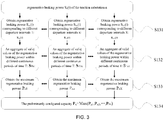
- As shown in
Fig. 3 , the step S13 comprises the following steps. - S131: Regenerative braking power Snx(t) corresponding to different departure intervals x is obtained according to the regenerative braking power Sn(t) of each traction substation calculated by the train power supply simulation and calculation, where x ∈ {1, 2, 3, ...X}, X denotes the number of departure intervals x, and the departure intervals x are related to a subway operation plan.
- It is to be noted that the "departure interval" refers to the time interval between departure of the last train and the next train, in seconds or minutes. The smaller the value of the departure interval is, the higher the departure frequency is. The departure intervals of domestic urban rail transit trains vary from two minutes to more than ten minutes. When the value of x in the "departure interval x" is different, that is, "
departure interval 1", "departure interval 2"..."departure interval X" refer to different departure intervals (which can also be interpreted as "the first departure interval", "the second departure interval"..."the Xth departure interval"), different departure interval x have different departure interval values. - In this step, every time one departure interval x is set, one train power supply simulation and calculation is performed to obtain the corresponding regenerative braking power Snx(t) under a different departure interval x.
- S132: According to the regenerative braking power Snx(t) under different departure intervals x, an aggregate of valid values STnx of the regenerative braking power within different continuous periods of time T under corresponding departure interval x of the traction substation n is obtained, where T is related to the maximum running velocity of the train;
wherein, under the departure interval x, the valid value of the regenerative braking power of the traction substation n within different continuous periods of time T is: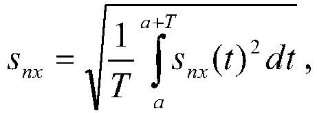
- S133: The valid value of the maximum regenerative braking power Pnx within different continuous periods of time T under the corresponding departure interval x is obtained according to the aggregate of valid values STnx.
- S134: The preliminarily configured capacity Pn of the regenerative braking energy recovery device corresponding to the traction substation n is obtained, where Pn=Max {Pn1, Pn2, ..., Pnx, ..., PnX}.
- During the preliminary configuring of the capacity of the regenerative energy recovery devices, the influence from the departure interval x is taken into consideration, and the difference in the departure interval x directly influences the distribution of the generative braking energy on the entire line; and, the valid value of the regenerative braking power Snx within a continuous period of time T is taken into consideration, and T is selected according to actual maximum velocity of the train and directly influences the amount of the regenerative braking energy during the braking process of a single train. By considering the departure interval x and the continuous period of time T, the practicability and scientific nature of the capacity configuration of the regenerative energy recovery devices are ensured.
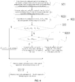
- As shown in
Fig. 4 , the step S2 comprises the following steps. - S21: An actually configured capacity Zn is converted according to the preliminarily configured capacity Pn of the regenerative braking energy recovery devices and the specification of the existing regenerative braking energy recovery devices.
- Based on the actual manufacturing and industrial standards, the capacity unit value of the existing regenerative braking energy recovery devices is generally 500 kW, and the capacity of a single regenerative braking energy recovery device is generally 0.5 MW, 1 MW, 1.5 MW, 2 MW, 2.5 MW, 3 MW, 3.5 MW and 4 MW. The capacity conversion principle follows the principle of rounding to nearest. For example, if the preliminarily configured capacity is 2.665 MW, the capacity is converted to 2.5 MW; and, if the preliminarily configured capacity is 2.825 MW, the capacity is converted to 3 MW.
- S22: When a regenerative braking energy recovery device is failed, whether adjacent regenerative braking energy recovery devices is capable to completely absorb the regenerative braking energy to be absorbed by the failed regenerative braking energy recovery device is determined; if so, the actually configured capacity of the adjacent regenerative braking energy recovery devices is an optimally configured capacity; and, if not, the capacity of the adjacent regenerative braking energy recovery devices is increased by an integral time of the capacity unit value of the regenerative braking energy recovery devices, to obtain optimally configured capacity of the adjacent regenerative braking energy recovery devices. By using the optimally configured capacity of the adjacent regenerative braking energy recovery devices, the regenerative braking energy to be absorbed by the failed regenerative braking energy recovery device can be completely absorbed.
- With continued reference to
Fig. 4 , the step S22 comprises the following steps. - S221: According to the S13, the preliminarily configured capacity Pn, the departure interval x and the valid value of the maximum regenerative braking power Pnx within different continuous periods of time T under the corresponding departure interval x of the failed regenerative braking energy recovery device is obtained, meanwhile, valid values of the maximum regenerative braking power of the adjacent regenerative braking energy recovery devices P(n-1)x and P(n+1)x within different continuous periods of time T under the corresponding departure interval x are obtained.
- S222: Whether Zn-1+Zn+1≥P(n-1)x+Pnx+P(n+1)x is true is determined; if so, the actually configured capacity Zn-1 and Zn+1 of adjacent traction substations n-1 and n+1 remain unchanged; and, if not, perform S223;
- S223: The magnitude of the distances from the traction substation n respectively to the adjacent traction substation n-1 and to the adjacent traction substation n+1 Ln(n-1) and Ln(n+1) is determined; if Ln(n-1)≥Ln(n+1), the actually configured capacity Zn+1 of the traction substation n+1 is increased by an integral time of the capacity unit value of the regenerative braking energy recovery devices to obtain an optimally configured capacity Qn+1, and the optimally configured capacity Qn-1 of the traction substation n-1 is the actually configured capacity Zn-1; and, if Ln(n-1)≤Ln(n+1), the actually configured capacity Zn-1 of the traction substation n-1 is increased by an integral time of the capacity unit value of the regenerative braking energy recovery devices to obtain an optimally configured capacity Qn-1, and the optimally configured capacity Qn+1 of the traction substation n+1 is the actually configured capacity Zn+1. By using the optimally configured capacity Qn+1 or Qn-1 that is increased by an integral time of the capacity unit value, the regenerative braking energy to be absorbed by the failed regenerative braking energy recovery device can be completely absorbed.
- Preferably, the capacity of the adjacent regenerative braking energy recovery devices is increased by 0.5 MW to finely adjust the converted capacity. If the capacity is too high, the capacity of the devices will be idle and wasted.
- To describe the step S22 more clearly, the step S221 to S223 are expressed in another way, specifically:
- S221: According to the preliminarily configured capacity Pn-1 and Pn+1 of the adjacent regenerative braking energy recovery devices of the failed regenerative braking energy recovery device obtained in the step S13, the actually configured capacity Zn-1 and Zn+1 of the two are converted according to the method in S21;
- S222: Whether Zn-1+Zn+1≥Pn-1+Pn+Pn+1 is true is determined; if so, the actually configured capacity Zn-1 and Zn+1 of adjacent traction substations n-1 and n+1 remains unchanged; and, if not, perform S223;
- S223: The magnitude of the distances from the traction substation n respectively to the adjacent traction substation n-1 and to the adjacent traction substation n+1 Ln(n-1) and Ln(n+1) is determined; if Ln(n-1)≥Ln(n+1), the actually configured capacity Zn+1 of the traction substation n+1 is increased by an integral time of the capacity unit value of the regenerative braking energy recovery devices to obtain an optimally configured capacity Qn+1, and the optimally configured capacity Qn-1 of the traction substation n-1 is the actually configured capacity Zn-1; and, if Ln(n-1)≤Ln(n+1), the actually configured capacity Zn-1 of the traction substation n-1 is increased by an integral time of the capacity unit value of the regenerative braking energy recovery devices to obtain an optimally configured capacity Qn-1, and the optimally configured capacity Qn+1 of the traction substation n+1 is the actually configured capacity Zn+1. By using the optimally configured capacity Qn+1 or Qn-1 that is increased by an integral time of the capacity unit value, the regenerative braking energy to be absorbed by the failed regenerative braking energy recovery device can be completely absorbed.
- Through the above steps S221 to S223, the n of the traction substation has a value from 1 to N, and the optimally configured capacity Q1 to QN of the regenerative braking energy recovery devices in the traction substations can be calculated.
- Preferably, the capacity of the adjacent regenerative braking energy recovery devices is increased by 0.5 MW to finely adjust the converted capacity. If the capacity is too high, the capacity of the device will be idle and wasted.
- During the optimally configuring of the capacity of the regenerative energy recovery devices, considering the sudden failure of the regenerative braking energy recovery device during the actual operation, the capability of adjacent regenerative braking energy recovery devices to share the power of the failed regenerative braking energy recovery device is calculated, the adjacent regenerative braking energy recovery devices with insufficient sharing capability are appropriately increased in capacity. In the adjacent regenerative braking energy recovery devices, the regenerative braking energy recovery device closest to the failed regenerative braking energy recovery device is selected and increased in capacity, so that the highest capability to share the power of the failed device is ensured. Meanwhile, the capacity is increased by 0.5 MW, so that the actual engineering experience and cost are fully taken into consideration and the better regenerative braking energy recovery effect is achieved.
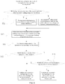
- As shown in
Fig. 5 , the step S3 comprises the following steps. - S31: Whether the optimally configured capacity Qn of the regenerative braking energy recovery device corresponding to the traction substation n is less than two times of the capacity unit value of the regenerative braking energy recovery devices (i.e., preferably 1 MW) is determined; if so, the regenerative braking energy recovery device is removed from the traction substation n; and, if not, the regenerative braking energy recovery device is installed in the traction substation n according to the optimally configured capacity Qn.
- The step S31 may be adjusted as required. For example, to further improve the recovered regenerative braking energy, whether the optimally configured capacity Qn of the regenerative braking energy recovery device corresponding to the traction substation n is less than the capacity unit value of the regenerative braking energy recovery devices (i.e., 0.5 MW) is determined; if so, the regenerative braking energy recovery device is removed from the traction substation n; and, if not, the regenerative braking energy recovery device is installed in the traction substation n according to the optimally configured capacity Qn.
- S32: The actual total number M of the regenerative braking energy recovery devices installed and the actual total configured capacity

- With reference to
Fig. 5 , the step S4 comprises the following steps. - S41: An average capacity

- S42: Whether the traction substation n is adjacent to a main substation is determined; if so, the regenerative braking energy recovery device corresponding to the traction substation n is configured as an energy storage unit; and, if not, perform S43.
- S43: Whether the optimally configured capacity Qn of the regenerative braking energy recovery device corresponding to the traction substation n is less than the average capacity E is determined; if so, the regenerative braking energy recovery device of the traction substation n is configured as an energy storage unit; and, if not, the regenerative braking energy recovery device of the traction substation n is configured as an energy feedback unit.
- By reasonably configuring the type of regenerative braking energy recovery devices, the deficiency of a single regenerative braking energy recovery device can be avoided.
- With reference to
Fig. 6 , an embodiment of the present application provides a system for configuring regenerative braking energy recovery devices in urban rail transit. The system uses the configuration method described above. - The system comprises a preliminary configurating unit, a capacity optimally configuring unit, a total number configurating unit and a type configurating unit; the preliminary configurating unit comprises a traction simulation and calculation module configured to perform traction simulation and calculation, and a train power supply simulation and calculation module configured to perform train power supply simulation and calculation;
the preliminary configurating unit is configured to perform train traction simulation and calculation, further to perform train power supply simulation and calculation according to the result of the train traction simulation and calculation to obtain a regenerative braking power Sn(t) of a traction substation n, and calculate a preliminarily configured capacity Pn of regenerative braking energy recovery device predetermined for the traction substation n according to the regenerative braking power Sn(t) of the traction substation n, where n ∈ {1, 2, 3, ...X} and N is the total number of traction substations; the capacity optimally configuring unit is configured to perform capacity optimal configuration for the regenerative braking energy recovery devices to obtain an optimally configured capacity Qn of the regenerative braking energy recovery devices corresponding to the traction substation n, according to the preliminarily configured capacity Pn of regenerative braking energy recovery devices and in combination with the specification of the existing regenerative braking energy recovery devices and by considering that when a regenerative braking energy recovery device is failed, adjacent regenerative braking energy recovery devices are capable to completely absorb the regenerative braking energy to be absorbed by the failed regenerative braking energy recovery device;
the total number configurating unit is configured to perform configuration for the total number M of the regenerative braking energy recovery devices installed according to the optimally configured capacity Qn of the regenerative braking energy recovery devices;
the type configurating unit is configured to further perform configuration for the type of the regenerative braking energy recovery devices of the traction substation n, according to the optimally configured capacity Qn and the total number M of the regenerative braking energy recovery devices installed as well as the locations of the regenerative braking energy recovery devices.
Claims (12)
- A method for configuring regenerative braking energy recovery devices in urban rail transit, successively comprising the following steps:S1: First, performing train traction simulation and calculation, further performing train power supply simulation and calculation according to the result of the train traction simulation and calculation to obtain a regenerative braking power Sn(t) of a traction substation n, and calculating a preliminarily configured capacity Pn of a regenerative braking energy recovery device predetermined for the traction substation n according to the regenerative braking power Sn(t) of the traction substation n, wherein n ∈ {1, 2, 3, ...N}, and N is the total number of traction substations;S2: According to the preliminarily configured capacity Pn of the regenerative braking energy recovery devices and in combination with the specification of the existing regenerative braking energy recovery devices, considering that when a regenerative braking energy recovery device is failed, adjacent regenerative braking energy recovery devices is capable to completely absorb the regenerative braking energy to be absorbed by the failed regenerative braking energy recovery device, performing capacity optimal configuration for the regenerative braking energy recovery devices to obtain an optimally configured capacity Qn of the regenerative braking energy recovery devices corresponding to the traction substation n;S3: Performing configuration for the total number M of the regenerative braking energy recovery devices installed according to the optimally configured capacity Qn of the regenerative braking energy recovery devices;S4: According to the magnitude of the optimally configured capacity Qn and the total number M of the regenerative braking energy recovery devices installed as well as the locations of the regenerative braking energy recovery devices, further performing configuration for the type of the regenerative braking energy recovery devices of the traction substation n.
- The method for configuring regenerative braking energy recovery devices in urban rail transit according to claim 1, wherein the step S1 comprises the following steps:S11: The train traction simulation and calculation: obtaining a traction energy consumption-velocity curve, a regenerative braking energy-velocity curve by a traction simulation algorithm of a traction simulation and calculation module through vehicle information parameters, dynamic performance parameters, resistance parameters, traction characteristic parameters and electric braking characteristic parameters;S12: The train power supply simulation and calculation: obtaining the regenerative braking power Sn(t) of the traction substation n by a power supply simulation and calculation algorithm of a power supply simulation module according to the traction energy consumption-velocity curve and the regenerative braking energy-velocity curve obtained by the traction simulation and calculation module and in combination with the impedance parameters of a power supply line, location parameters and capacity of the traction substation, number of departure;S13: Preliminary configuration and calculation of the capacity of the regenerative braking energy recovery devices: performing preliminary configuration for the capacity of the regenerative braking energy recovery device of the traction substation n according to the obtained regenerative braking power Sn(t) of the traction substation n.
- The method for configuring regenerative braking energy recovery devices in urban rail transit according to claim 2, wherein the step S13 comprises the following steps:S131: Obtaining regenerative braking power Snx(t) corresponding to different departure intervals x according to the regenerative braking power Sn(t) of the traction substation n calculated by the train power supply simulation and calculation, where x ∈ {1, 2, 3, ...X} , X denotes the number of departure intervals x, and the departure intervals x are related to a subway operation plan;S132: According to the regenerative braking power Snx(t) under different departure intervals x, obtaining an aggregate of valid values STnx of the regenerative braking power within different continuous periods of time T under the corresponding departure interval x of the traction substation n, where T is related to the maximum running velocity of the train;S133: Obtaining the valid value of the maximum regenerative braking power Pnx within different continuous periods of time T under the corresponding departure interval x according to the aggregate of valid values STnx;S134: Obtaining the preliminarily configured capacity Pn of the regenerative braking energy recovery device corresponding to the traction substation n, where Pn=Max {Pn1, Pn2, ..., Pnx, ..., PnX}.
- The method for configuring regenerative braking energy recovery devices in urban rail transit according to claim 3, wherein the step S2 comprises the following steps:S21: Converting an actually configured capacity Zn according to the preliminarily configured capacity Pn of the regenerative braking energy recovery devices and the specification of the existing regenerative braking energy recovery devices;S22: Determining when a regenerative braking energy recovery device is failed, whether adjacent regenerative braking energy recovery devices is capable to completely absorb the regenerative braking energy to be absorbed by the failed regenerative braking energy recovery device; if so, the actually configured capacity of the adjacent regenerative braking energy recovery devices is an optimally configured capacity; and, if not, increasing the capacity of the adjacent regenerative braking energy recovery devices by an integral time of the capacity unit value of the regenerative braking energy recovery devices, to obtain optimally configured capacity of the adjacent regenerative braking energy recovery devices.
- The method for configuring regenerative braking energy recovery devices in urban rail transit according to claim 4, wherein the step S22 comprises the following steps:S221: According to the S13, obtaining the preliminarily configured capacity Pn, the departure interval x and the valid value of the maximum regenerative braking power Pnx within different continuous periods of time T under the corresponding departure interval x of the failed regenerative braking energy recovery device, meanwhile, obtaining valid values of the maximum regenerative braking power of the adjacent regenerative braking energy recovery devices P(n-1)x and P(n+1)x within different continuous periods of time T under the corresponding departure interval x;S222: Determining whether Zn-1+Zn+1≥P(n-1)x+Pnx+P(n+1)x is true; if so, the actually configured capacity Zn-1 and Zn+1 of adjacent traction substations n-1 and n+1 remain unchanged; and, if not, perform S223;S223: Determining the magnitude of the distances from the traction substation n respectively to the adjacent traction substation n-1 and to the adjacent traction substation n+1 Ln(n-1) and Ln(n+1); if Ln(n-1)≥Ln(n+1), increasing the actually configured capacity Zn+1 of the traction substation n+1 by an integral time of the capacity unit value of the regenerative braking energy recovery devices to obtain an optimally configured capacity Qn+1, and the optimally configured capacity Qn-1 of the traction substation n-1 is the actually configured capacity Zn-1; if Ln(n-1)≤Ln(n+1), increasing the actually configured capacity Zn-1 of the traction substation n-1 by an integral time of the capacity unit value of the regenerative braking energy recovery devices to obtain an optimally configured capacity Qn-1, and the optimally configured capacity Qn+1 of the traction substation n+1 is the actually configured capacity Zn+1.
- The method for configuring regenerative braking energy recovery devices in urban rail transit according to claim 4, wherein the step S22 comprises the following steps:S221: According to the step S13, obtaining the preliminarily configured capacity Pn-1 and Pn+1 of the adjacent failed regenerative braking energy recovery devices, and according to the method in S21, converting the actually configured capacity Zn-1 and Zn+1 of the two;S222: Determining whether Zn-1+Zn+1≥Pn-1+Pn+Pn+1 is true; if so, the actually configured capacity Zn-1 and Zn+1 of adjacent traction substations n-1 and n+1 remain unchanged; and, if not, perform S223;S223: Determining the magnitude of the distances from the traction substation n respectively to the adjacent traction substation n-1 and to the adjacent traction substation n+1 Ln(n-1) and Ln(n+1); if Ln(n-1)≥Ln(n+1), increasing the actually configured capacity Zn+1 of the traction substation n+1 by an integral time of the capacity unit value of the regenerative braking energy recovery devices to obtain an optimally configured capacity Qn+1, and the optimally configured capacity Qn-1 of the traction substation n-1 is the actually configured capacity Zn-1; and, if Ln(n-1) ≤ Ln(n+1), increasing the actually configured capacity Zn-1 of the traction substation n-1 by an integral time of the capacity unit value of the regenerative braking energy recovery devices to obtain an optimally configured capacity Qn-1, and the optimally configured capacity Qn+1 of the traction substation n+1 is the actually configured capacity Zn+1.
- The method for configuring regenerative braking energy recovery devices in urban rail transit according to claim 1, wherein the step S3 comprises the following steps:S31: Determining whether the optimally configured capacity Qn of the regenerative braking energy recovery device corresponding to the traction substation n is less than two times of the capacity unit value of the regenerative braking energy recovery devices; if so, removing the regenerative braking energy recovery device from the traction substation n; and, if not, installing the regenerative braking energy recovery device in the traction substation n according to the optimally configured capacity Qn;S32: Obtaining the actual total number M of the regenerative braking energy recovery devices installed and the actual total configured capacity

- The method for configuring regenerative braking energy recovery devices in urban rail transit according to claim 1, wherein the step S3 comprises the following steps:S31: Determining whether the optimally configured capacity Qn of the regenerative braking energy recovery device corresponding to the traction substation n is less than the capacity unit value of the regenerative braking energy recovery devices; if so, removing the regenerative braking energy recovery device from the traction substation n; and, if not, installing the regenerative braking energy recovery device in the traction substation n according to the optimally configured capacity Qn;S32: Obtaining the actual total number M of the regenerative braking energy recovery devices installed and the actual total configured capacity

- The method for configuring regenerative braking energy recovery devices in urban rail transit according to claim 7 or 8, wherein the step S4 comprises the following steps:S41: Calculating an average capacity
 S42: Determining whether the traction substation n is adjacent to a main substation; if so, configuring the regenerative braking energy recovery device corresponding to the traction substation n as an energy storage unit; and, if not, performing S43;S43: Determining whether the optimally configured capacity Qn of the regenerative braking energy recovery device corresponding to the traction substation n is less than the average capacity E; if so, configuring the regenerative braking energy recovery device of the traction substation n as an energy storage unit; and, if not, configuring regenerative braking energy recovery device of the traction substation n as an energy feedback unit.
 - The method for configuring regenerative braking energy recovery devices in urban rail transit according to claim 2, wherein, the vehicle information parameters comprise vehicle type, marshaling and load; the dynamic performance parameters comprise the acceleration and deceleration of the vehicle; the resistance parameters comprise starting resistance and basic resistance; the traction characteristic parameters comprise traction force; and, the electric braking characteristic parameters comprise electric braking force.
- The method for configuring regenerative braking energy recovery devices in urban rail transit according to claim 4, wherein, in S22, increasing the capacity of the adjacent regenerative braking energy recovery devices by one time of the capacity unit value.
- A system for configuring regenerative braking energy recovery devices in urban rail transit, the system uses the configuration method according to anyone of claim 1 to 11, wherein,
the system comprises a preliminary configurating unit, a capacity optimally configuring unit, a total number configurating unit and a type configurating unit;
the preliminary configurating unit is configured to perform train traction simulation and calculation, further to perform train power supply simulation and calculation according to the result of train traction simulation and calculation to obtain a regenerative braking power Sn(t) of a traction substation n, and calculate a preliminarily configured capacity Pn of regenerative braking energy recovery device predetermined for the traction substation n according to the regenerative braking power Sn(t) of the traction substation n, where n ∈ {1, 2, 3, ...X} and N is the total number of traction substations; the capacity optimally configuring unit is configured to perform capacity optimal configuration for the regenerative braking energy recovery devices to obtain an optimally configured capacity Qn of the regenerative braking energy recovery devices corresponding to the traction substation n, according to the preliminarily configured capacity Pn of regenerative braking energy recovery devices and in combination with the specification of the existing regenerative braking energy recovery devices and by considering that when a regenerative braking energy recovery device is failed, adjacent regenerative braking energy recovery devices are capable to completely absorb the regenerative braking energy to be absorbed by the failed regenerative braking energy recovery device;
the total number configurating unit is configured to perform configuration for the total number M of the regenerative braking energy recovery devices installed according to the optimally configured capacity Qn of the regenerative braking energy recovery devices;
the type configurating unit is configured to further perform configuration for the type of the regenerative braking energy recovery devices of the traction substation n, according to the optimally configured capacity Qn and the total number M of the regenerative braking energy recovery devices installed as well as the locations of the regenerative braking energy recovery devices.
Applications Claiming Priority (2)
| Application Number | Priority Date | Filing Date | Title |
|---|---|---|---|
| CN201810290381.XA CN108437806B (en) | 2018-03-30 | 2018-03-30 | The configuration system and method for urban track traffic regenerating braking energy recyclable device |
| PCT/CN2018/124317 WO2019184488A1 (en) | 2018-03-30 | 2018-12-27 | Configuration method and system for urban rail transit regenerative braking energy recycling devices |
Publications (2)
| Publication Number | Publication Date |
|---|---|
| EP3705339A1 true EP3705339A1 (en) | 2020-09-09 |
| EP3705339A4 EP3705339A4 (en) | 2021-01-27 |
Family
ID=63198164
Family Applications (1)
| Application Number | Title | Priority Date | Filing Date |
|---|---|---|---|
| EP18913037.0A Withdrawn EP3705339A4 (en) | 2018-03-30 | 2018-12-27 | Configuration method and system for urban rail transit regenerative braking energy recycling devices |
Country Status (9)
| Country | Link |
|---|---|
| US (1) | US11065965B2 (en) |
| EP (1) | EP3705339A4 (en) |
| JP (1) | JP6937930B2 (en) |
| KR (1) | KR102213266B1 (en) |
| CN (1) | CN108437806B (en) |
| IL (1) | IL276454A (en) |
| MY (1) | MY183939A (en) |
| RU (1) | RU2742839C1 (en) |
| WO (1) | WO2019184488A1 (en) |
Families Citing this family (15)
| Publication number | Priority date | Publication date | Assignee | Title |
|---|---|---|---|---|
| CN108437806B (en) * | 2018-03-30 | 2019-09-13 | 中车青岛四方车辆研究所有限公司 | The configuration system and method for urban track traffic regenerating braking energy recyclable device |
| CN109116752A (en) * | 2018-08-31 | 2019-01-01 | 北京交通大学 | A kind of the dynamic model analogue system and control method of urban track traffic |
| CN109449963B (en) * | 2018-12-19 | 2021-11-19 | 南京亚派科技股份有限公司 | Capacity allocation and control method of hybrid regenerative electric energy absorption and utilization device |
| CN109733201B (en) * | 2019-01-16 | 2021-10-19 | 重庆交通大学 | Control method of urban rail train regenerative braking energy absorption and utilization system |
| CN113752898A (en) * | 2020-06-04 | 2021-12-07 | 株洲变流技术国家工程研究中心有限公司 | Battery capacity determination method for pure electric vehicle and related device |
| CN111806241B (en) * | 2020-06-28 | 2022-02-18 | 同济大学 | Method for determining regenerative electric energy recovery space of rail transit train |
| CN112590867B (en) * | 2020-12-21 | 2022-05-27 | 中车青岛四方车辆研究所有限公司 | Urban rail train group speed optimization method and system based on vehicle-to-vehicle communication |
| CN113054751B (en) * | 2021-03-25 | 2022-07-15 | 北京交通大学 | Coordination optimization method for urban rail transit vehicle-ground energy storage system based on information interaction |
| CN113381426B (en) * | 2021-07-16 | 2022-09-02 | 盾石磁能科技有限责任公司 | Capacity configuration method of flywheel energy storage device, terminal and storage medium |
| CN113346534B (en) * | 2021-08-05 | 2021-11-23 | 中铁电气化勘测设计研究院有限公司 | Energy storage type regenerative energy absorption device simulation method suitable for load flow simulation calculation |
| CN113743828B (en) * | 2021-09-23 | 2023-04-07 | 西南交通大学 | Urban rail transit operation scheduling method and system |
| CN114537150B (en) * | 2022-01-25 | 2023-09-12 | 兰州交通大学 | High-speed railway long and large ramp regenerative braking energy hybrid energy storage optimal configuration method |
| CN115085295B (en) * | 2022-07-27 | 2022-11-18 | 深圳量云能源网络科技有限公司 | Reactive power regulation method and system based on converter energy management |
| CN115600458A (en) * | 2022-10-11 | 2023-01-13 | 苏州大学(Cn) | Stray current dynamic distribution calculation method considering three-dimensional ground system |
| CN115675191B (en) * | 2023-01-04 | 2023-03-21 | 新誉轨道交通科技有限公司 | Train-ground joint control energy management method, system, equipment and storage medium |
Family Cites Families (22)
| Publication number | Priority date | Publication date | Assignee | Title |
|---|---|---|---|---|
| CH580263A5 (en) * | 1973-12-18 | 1976-09-30 | Pretema Ag | |
| CH594849A5 (en) | 1975-04-16 | 1978-01-31 | Wunderlin Willy | |
| DD261485A3 (en) * | 1986-11-26 | 1988-11-02 | Elektroprojekt Anlagenbau Veb | CIRCUIT ARRANGEMENT FOR ENERGY SUPPLY OF DRIVING NETWORKS FOR ELECTRIC DC MOTOR VEHICLES WITH NET BRAKING DEVICES |
| JP4184879B2 (en) * | 2003-07-03 | 2008-11-19 | 株式会社日立製作所 | Railway vehicle drive system |
| US20050279242A1 (en) * | 2004-03-01 | 2005-12-22 | Railpower Technologies Corp. | Cabless hybrid locomotive |
| FR2915435B1 (en) * | 2007-04-25 | 2009-08-07 | Alstom Transport Sa | SYSTEM, SUBSTATION AND METHOD FOR RECOVERING THE BRAKING ENERGY OF RAILWAY VEHICLES, RAILWAY VEHICLES FOR THIS SYSTEM. |
| JP5525492B2 (en) * | 2011-07-21 | 2014-06-18 | 株式会社日立製作所 | Railway power system |
| JP6054122B2 (en) * | 2012-09-28 | 2016-12-27 | 株式会社東芝 | Railway power management equipment |
| NO20130229A1 (en) * | 2013-02-12 | 2014-01-20 | Maintech As | Facility for energy supply of trains |
| CN103419680B (en) * | 2013-07-29 | 2015-08-19 | 华北电力大学(保定) | A kind of DC traction power-supply system based on distributed power source |
| CN103840477B (en) * | 2014-01-03 | 2015-09-23 | 南车株洲电力机车研究所有限公司 | Electric railway traction is powered energy storage device and method thereof |
| JP6363465B2 (en) * | 2014-10-21 | 2018-07-25 | 株式会社東芝 | Power storage device |
| CN104580356B (en) | 2014-11-24 | 2018-04-06 | 中车青岛四方机车车辆股份有限公司 | Train workshop method for transmitting signals and device |
| JP6539043B2 (en) * | 2014-12-26 | 2019-07-03 | 株式会社日立製作所 | Railway feeding system and railway feeding control method |
| FR3031849B1 (en) * | 2015-01-16 | 2017-02-17 | Alstom Transp Tech | POWER SUPPLY CONVERTER AND / OR SUBSTATION FOR RECOVERING BRAKING ENERGY |
| JP6342082B2 (en) * | 2015-08-27 | 2018-06-13 | 三菱電機株式会社 | Station building auxiliary power supply |
| CN105774569B (en) | 2016-03-11 | 2017-11-10 | 中车青岛四方车辆研究所有限公司 | The rail vehicle traction inversion system and method for integrated energy storage device charge and discharge control |
| RU2636847C1 (en) * | 2016-08-03 | 2017-11-28 | Илья Александрович Кондрашов | Dc traction substation with flywheel storage |
| CN106080215B (en) | 2016-08-23 | 2019-05-21 | 中车青岛四方机车车辆股份有限公司 | A kind of rail traffic Brake Energy recycling system and hybrid power rail traffic |
| CN206031089U (en) * | 2016-08-26 | 2017-03-22 | 比亚迪股份有限公司 | A regeneration energy absorption energy memory for tractor -trailer train |
| CN107380187B (en) * | 2016-11-28 | 2019-12-03 | 盾石磁能科技有限责任公司 | Rail traffic regenerating braking energy comprehensive recycling device and method |
| CN108437806B (en) * | 2018-03-30 | 2019-09-13 | 中车青岛四方车辆研究所有限公司 | The configuration system and method for urban track traffic regenerating braking energy recyclable device |
-
2018
- 2018-03-30 CN CN201810290381.XA patent/CN108437806B/en active Active
- 2018-12-27 JP JP2020545480A patent/JP6937930B2/en active Active
- 2018-12-27 MY MYPI2020003672A patent/MY183939A/en unknown
- 2018-12-27 RU RU2020123004A patent/RU2742839C1/en active
- 2018-12-27 KR KR1020207018929A patent/KR102213266B1/en active IP Right Grant
- 2018-12-27 WO PCT/CN2018/124317 patent/WO2019184488A1/en unknown
- 2018-12-27 EP EP18913037.0A patent/EP3705339A4/en not_active Withdrawn
-
2020
- 2020-08-03 IL IL276454A patent/IL276454A/en active IP Right Grant
- 2020-08-26 US US17/003,910 patent/US11065965B2/en active Active
Also Published As
| Publication number | Publication date |
|---|---|
| JP6937930B2 (en) | 2021-09-22 |
| MY183939A (en) | 2021-03-17 |
| IL276454A (en) | 2020-09-30 |
| US11065965B2 (en) | 2021-07-20 |
| JP2021508645A (en) | 2021-03-11 |
| KR102213266B1 (en) | 2021-02-08 |
| CN108437806A (en) | 2018-08-24 |
| RU2742839C1 (en) | 2021-02-11 |
| WO2019184488A1 (en) | 2019-10-03 |
| EP3705339A4 (en) | 2021-01-27 |
| KR20200088899A (en) | 2020-07-23 |
| US20200391596A1 (en) | 2020-12-17 |
| CN108437806B (en) | 2019-09-13 |
Similar Documents
| Publication | Publication Date | Title |
|---|---|---|
| US11065965B2 (en) | Method and system for configuring regenerative braking energy recovery devices in urban rail transit | |
| CN101376344B (en) | Multiple-target integrated control energy-saving method of electric power supply system for subway | |
| CN107933326B (en) | Double-source trackless electric vehicle electric coupling control method and power device | |
| CN110460077A (en) | A kind of new energy system and control method for urban rail Traction networks | |
| CN104346525B (en) | Method for calculating accumulated power of multiple trains of traction substation of electricity supply system of urban rail transit | |
| Shen et al. | Study of trackside photovoltaic power integration into the traction power system of suburban elevated urban rail transit line | |
| CN104527960A (en) | Ship braking energy control system and method | |
| CN206664310U (en) | A kind of rush-harvesting and rush-planting direct-current charging post charging system | |
| Yuan et al. | Optimal dispatching of high-speed railway power system based on hybrid energy storage system | |
| CN111864774B (en) | Peak clipping and valley filling control method for in-phase hybrid energy storage power supply structure of electrified railway | |
| Lianfu et al. | Research on the integrated braking energy recovery strategy based on super-capacitor energy storage | |
| CN109353367A (en) | Regeneration energy recycling system and control method based on flywheel energy storage and resistive braking | |
| Chen et al. | Analysis of dynamic load behavior for electrified mass rapid transit systems | |
| CN113381426B (en) | Capacity configuration method of flywheel energy storage device, terminal and storage medium | |
| Wei et al. | Research on three-level bi-directional dc-dc converter and its control strategy used for energy storage system of electric wheeled tramcar | |
| Yang et al. | Improved control strategy of energy storage system considering train operation states | |
| Zhu et al. | Hybrid energy storage system of storage battery/super capacitor for mine electric locomotive | |
| CN204578108U (en) | A kind of converter device and system | |
| CN110053665A (en) | A kind of new-energy automobile chassis structure | |
| CN115800350B (en) | Rail transit vehicle and regenerative braking energy comprehensive utilization device and method thereof | |
| Wu et al. | Simulation research of energy management strategy for range extended electric bus | |
| Chen et al. | Design of main transformer capacity for electrified railway power systems | |
| Sandidzadeh et al. | Controlling Train Power Consumption with Energy Storage Based on Fuzzy Control-Case Study on Line 3 of Tehran Metro | |
| Liang et al. | Energy Management Strategy Based on Dynamic Threshold for Energy Recovery System in Rail Transit | |
| Wang et al. | Research and simulation on energy storage system of dual power rail vehicle |
Legal Events
| Date | Code | Title | Description |
|---|---|---|---|
| STAA | Information on the status of an ep patent application or granted ep patent |
Free format text: STATUS: THE INTERNATIONAL PUBLICATION HAS BEEN MADE |
|
| PUAI | Public reference made under article 153(3) epc to a published international application that has entered the european phase |
Free format text: ORIGINAL CODE: 0009012 |
|
| STAA | Information on the status of an ep patent application or granted ep patent |
Free format text: STATUS: REQUEST FOR EXAMINATION WAS MADE |
|
| 17P | Request for examination filed |
Effective date: 20200605 |
|
| AK | Designated contracting states |
Kind code of ref document: A1 Designated state(s): AL AT BE BG CH CY CZ DE DK EE ES FI FR GB GR HR HU IE IS IT LI LT LU LV MC MK MT NL NO PL PT RO RS SE SI SK SM TR |
|
| AX | Request for extension of the european patent |
Extension state: BA ME |
|
| A4 | Supplementary search report drawn up and despatched |
Effective date: 20210113 |
|
| RIC1 | Information provided on ipc code assigned before grant |
Ipc: B60L 7/18 20060101AFI20201222BHEP Ipc: B60L 9/04 20060101ALI20201222BHEP Ipc: B60L 7/12 20060101ALI20201222BHEP |
|
| DAV | Request for validation of the european patent (deleted) | ||
| DAX | Request for extension of the european patent (deleted) | ||
| STAA | Information on the status of an ep patent application or granted ep patent |
Free format text: STATUS: EXAMINATION IS IN PROGRESS |
|
| 17Q | First examination report despatched |
Effective date: 20210709 |
|
| STAA | Information on the status of an ep patent application or granted ep patent |
Free format text: STATUS: THE APPLICATION IS DEEMED TO BE WITHDRAWN |
|
| 18D | Application deemed to be withdrawn |
Effective date: 20220225 |