EP3705164A1 - Leckagemelder für filterelemente - Google Patents
Leckagemelder für filterelemente Download PDFInfo
- Publication number
- EP3705164A1 EP3705164A1 EP20000074.3A EP20000074A EP3705164A1 EP 3705164 A1 EP3705164 A1 EP 3705164A1 EP 20000074 A EP20000074 A EP 20000074A EP 3705164 A1 EP3705164 A1 EP 3705164A1
- Authority
- EP
- European Patent Office
- Prior art keywords
- pressure medium
- filter
- detector according
- bluff body
- leak detector
- Prior art date
- Legal status (The legal status is an assumption and is not a legal conclusion. Google has not performed a legal analysis and makes no representation as to the accuracy of the status listed.)
- Granted
Links
Images


Classifications
-
- B—PERFORMING OPERATIONS; TRANSPORTING
- B01—PHYSICAL OR CHEMICAL PROCESSES OR APPARATUS IN GENERAL
- B01D—SEPARATION
- B01D35/00—Filtering devices having features not specifically covered by groups B01D24/00 - B01D33/00, or for applications not specifically covered by groups B01D24/00 - B01D33/00; Auxiliary devices for filtration; Filter housing constructions
- B01D35/14—Safety devices specially adapted for filtration; Devices for indicating clogging
- B01D35/143—Filter condition indicators
-
- B—PERFORMING OPERATIONS; TRANSPORTING
- B01—PHYSICAL OR CHEMICAL PROCESSES OR APPARATUS IN GENERAL
- B01D—SEPARATION
- B01D25/00—Filters formed by clamping together several filtering elements or parts of such elements
- B01D25/12—Filter presses, i.e. of the plate or plate and frame type
-
- G—PHYSICS
- G01—MEASURING; TESTING
- G01F—MEASURING VOLUME, VOLUME FLOW, MASS FLOW OR LIQUID LEVEL; METERING BY VOLUME
- G01F1/00—Measuring the volume flow or mass flow of fluid or fluent solid material wherein the fluid passes through a meter in a continuous flow
- G01F1/05—Measuring the volume flow or mass flow of fluid or fluent solid material wherein the fluid passes through a meter in a continuous flow by using mechanical effects
- G01F1/20—Measuring the volume flow or mass flow of fluid or fluent solid material wherein the fluid passes through a meter in a continuous flow by using mechanical effects by detection of dynamic effects of the flow
- G01F1/28—Measuring the volume flow or mass flow of fluid or fluent solid material wherein the fluid passes through a meter in a continuous flow by using mechanical effects by detection of dynamic effects of the flow by drag-force, e.g. vane type or impact flowmeter
-
- G—PHYSICS
- G01—MEASURING; TESTING
- G01M—TESTING STATIC OR DYNAMIC BALANCE OF MACHINES OR STRUCTURES; TESTING OF STRUCTURES OR APPARATUS, NOT OTHERWISE PROVIDED FOR
- G01M3/00—Investigating fluid-tightness of structures
- G01M3/02—Investigating fluid-tightness of structures by using fluid or vacuum
- G01M3/26—Investigating fluid-tightness of structures by using fluid or vacuum by measuring rate of loss or gain of fluid, e.g. by pressure-responsive devices, by flow detectors
Definitions
- the invention relates to a leakage detector for filter elements of a filter press, which comprises several filter elements clamped together at the edge, consisting of a support wall with a circumferential plate frame, which between them form filter chambers with inlets opening into them for the suspension to be filtered and on one or both sides in the edge area tightly with the Carrying pressure membranes connected to the filter element, which can be moved forward into the filter chamber by a pressure medium, the pressure medium being supplied or discharged via a pressure medium bore opening into the edge of the filter element, into which a flow sensor through which the pressure medium flows can be inserted.
- Such a leakage detector is for example from EP 1084742 became known, which has proven itself in practice and is used accordingly in a variety of ways. However, if the repressing system is contaminated, malfunctions can occur that require removal and cleaning.
- the invention is therefore based on the object of improving a leakage detector of the type mentioned at the beginning with regard to its structural geometry in such a way that it becomes overall less sensitive to dirt, in particular dirt deposits can hardly settle.
- the flow sensor has an axially displaceable baffle which is essentially cylindrical in cross section and which is provided on its outer surface with at least one, preferably two or more flow channels extending axially thereof, the baffle having one Has magnets, via whose magnetic field the position of the bluff body is detected by a magnetic sensor also arranged in the edge area or in the plate frame and provided as a signal for further processing.
- the advantage achieved by the invention is essentially that the geometry of the damming body is very insensitive to dirt in the repressing system, with dirt in the repressing system, in particular due to plate defects or an unclean environment, being regularly expected. However, should cleaning become necessary due to heavy soiling, this can be done quickly and without effort thanks to the simple structure. Even if the bluff body is stuck due to The operation of the filter plate is still possible because of soiling, since even a stuck damming body can be overflown in both flow directions. Furthermore, the bluff body geometry can be optimized in a simple manner in problematic applications, since the bluff body can easily be exchanged. As a result, the cross-sectional size and the geometry can be varied, which also allows adaptation to different media.
- the flow sensor is screwed into the pressure medium bore with a threaded flange.
- a threaded flange In this way, it is also possible, in particular, to retrofit filter plates by simply drilling the pressure medium bore onto the suitable pressure gauge and providing it with a thread.
- the bluff body is guided in a sleeve adjoining the threaded flange, the sleeve being arranged either inside or outside the panel frame. If there is sufficient space in the plate frame, the sleeve and thus the bluff body can be arranged within the plate frame; however, if the plate frame is narrow, it is easily possible to provide the sleeve outside the frame.
- the bluff body is held in the rest position by means of a helical spring guided in the sleeve or the pressure medium hole, the helical spring being supported on the side facing away from the bluff body on an annular shoulder of the sleeve or the pressure medium hole.
- the bluff body is provided on both end faces with a flat blind hole which is open towards the individual flow channels.
- the flow channels can basically be designed as desired with regard to their cross-sectional shape; In the context of the invention, however, it has proven to be expedient if the flow channels have a circular edge contour, since this largely avoids deposits of dirt from the repressing system in the area of the baffle.
- the bluff body is provided with a rounding or a bevel on its frontal edges.
- the magnetic sensor can be designed in detail as a digitally operating switching element or as an analog linear sensor. If only a digital switching signal is recorded, the filling level can be derived from the switching duration. When evaluating an analog, possibly digitized, signal, the flow rate and, taking into account the time component, also the filling quantity can be determined.
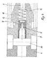
- the leakage detector 2 shown in the drawing is intended for filter elements of a filter press which comprises several filter elements clamped together at the edge and which consist of a support wall with a circumferential plate frame 1.
- the filter elements form filter chambers between them with inlets opening into them for the suspension to be filtered.
- the pressure medium is supplied or removed via a pressure medium bore 3 opening into the edge of the filter element.
- a flow sensor 4 through which the pressure medium flows is provided in the pressure medium bore.
- the flow sensor 4 has a substantially cylindrical, axially displaceable baffle 5 in cross section, which is provided on its outer surface with flow channels 6 extending in the axial direction.
- flow channels 6 extending in the axial direction.
- two or preferably four flow channels 6 are arranged on the jacket surface.
- the bluff body 5 also has a magnet 7, via whose magnetic field the position of the bluff body 5 can be detected.
- a magnetic sensor 8 which provides a signal for further electronic processing, is also arranged in the edge area or in the plate frame 1.
- the flow sensor 4 is screwed into the pressure medium bore 3 with a threaded flange 9, which makes it possible to retrofit already existing pressure medium bores 3 with such a flow sensor 4, in which only a threaded bore adapted to the flow sensor 4 has to be made.
- the bluff body 5 is guided directly in the pressure medium bore 3 and rests against the end face of the threaded flange 9 in the rest position.
- the bluff body 5 is guided in a sleeve adjoining the threaded flange 9, the sleeve being arranged either inside or outside the panel frame 1.
- the bluff body 5 is held by means of a helical spring 10 guided in the sleeve or the pressure medium bore 3 in the rest position, that is, in frontal contact with the threaded flange 9.
- the helical spring 10 is supported on an annular shoulder 11 of the pressure medium bore 3 - or the sleeve.
- the bluff body 5 is provided on both end faces with a flat blind hole 12, which is open towards the individual flow channels 6.
- FIG. 4 Another embodiment variant is shown in which the individual leakage alarms are connected to one another via a bore 13 extending transversely in the plate frame 1, so that each membrane filter element does not have to be controlled individually with pressure medium.
Landscapes
- Physics & Mathematics (AREA)
- General Physics & Mathematics (AREA)
- Chemical & Material Sciences (AREA)
- Chemical Kinetics & Catalysis (AREA)
- Fluid Mechanics (AREA)
- Measuring Fluid Pressure (AREA)
- Examining Or Testing Airtightness (AREA)
- Control Of Motors That Do Not Use Commutators (AREA)
Abstract
Description
- Die Erfindung betrifft einen Leckagemelder für Filterelemente einer Filterpresse, die mehrere randseitig zusammengespannte, aus einer Stützwand mit einem umlaufenden Plattenrahmen bestehende Filterelemente umfasst, die zwischen sich Filterkammern mit darin mündenden Einläufen für die zu filtrierende Suspension bilden und ein- oder beidseitig im Randbereich dicht mit dem Filterelement verbundene, durch ein Druckmittel in die Filterkammer vorbewegbare Preßmembranen tragen, wobei das Druckmittel über eine randseitig in dem Filterelement mündende Druckmittelbohrung zu- bzw. abgeführt wird, in die ein vom Druckmittel durchflossener Strömungssensor einsetzbar ist.
- Ein derartiger Leckagemelder ist beispielsweise aus der
EP 1084742 bekannt geworden, der sich in der Praxis bewährt hat und entsprechend vielfältig eingesetzt wird. Bei Verschmutzungen im Nachpresssystem können jedoch Störungen auftreten, die einen Ausbau und eine Reinigung erforderlich machen. Daher liegt der Erfindung die Aufgabe zugrunde, eine Leckagemelder der eingangs genannten Art hinsichtlich seiner Aufbaugeometrie dahingehend zu verbessern, dass er insgesamt unempfindlicher gegen Schmutz wird, insbesondere Schmutzablagerungen sich kaum absetzen können. - Diese Aufgabe wird nach der Erfindung dadurch gelöst, dass der Strömungssensor einen im Querschnitt im wesentlichen zylindrischen, axial verschiebbaren Staukörper aufweist, der an seiner Mantelfläche mit wenigstens einem, bevorzugt zwei oder vielfachen hiervon sich in axialer Richtung erstreckenden Strömungskanälen versehen ist, wobei der Staukörper einen Magneten aufweist, über dessen Magnetfeld die Position des Staukörpers durch einen ebenfalls im Randbereich bzw. im Plattenrahmen angeordneten Magnetsensor erfasst und als Signal zur Weiterverarbeitung bereitgestellt wird.
- Der durch die Erfindung erreichte Vorteil besteht zunächst im Wesentlichen darin, dass die Geometrie des Staukörpers sehr umempfindlich gegen Schmutz im Nachpresssystem ist, wobei mit Schmutz im Nachpresssystem insbesondere aufgrund von Plattendefekten oder unsauberer Umgebung regelmäßig gerechnet werden muss. Sollte dennoch aufgrund starker Verschmutzung eine Reinigung erforderlich werden, so ist dies aufgrund des einfachen Aufbaus schnell und ohne Mühe möglich. Selbst bei festsitzendem Staukörper aufgrund von Verschmutzung ist der Betrieb der Filterplatte nach wie vor möglich, da selbst ein festsitzender Staukörper in beiden Flussrichtungen überströmt werden kann. Desweiteren kann die Staukörpergeometrie bei problematischen Anwendungen auf einfache Weise optimiert werden, da der Staukörper ohne Weiteres leicht ausgetauscht werden kann. Dadurch kann eine Variation der Querschnittsgröße und der Geometrie vorgenommen werden, wodurch auch eine Anpassung an unterschiedliche Medien möglich ist.
- In bevorzugter Ausführungsform der Erfindung ist der Strömungssensor mit einem Gewindeflansch in der Druckmittelbohrung eingeschraubt. Hierdurch ist es insbesondere auch möglich, Filterplatten nachträglich nachzurüsten, in dem lediglich die Druckmittelbohrung auf den geeigneten Druckmesser aufgebohrt und mit einem Gewinde versehen wird.
- Weiter hat es sich im Rahmen der Erfindung als vorteilhaft erwiesen, wenn der Staukörper in einer an dem Gewindeflansch anschließenden Hülse geführt ist, wobei die Hülse entweder innerhalb oder außerhalb des Plattenrahmens angeordnet ist. Sofern im Plattenrahmen ausreichend Platz vorhanden ist, kann die Hülse und damit der Staukörper innerhalb des Plattenrahmens angeordnet sein; ist der Plattenrahmen dagegen schmal, besteht ohne Weiteres die Möglichkeit, die Hülse außerhalb des Rahmens vorzusehen.
- Es besteht jedoch auch die ebenfalls vorteilhafte, insbesondere einfach gestaltete Möglichkeit, dass der Staukörper in der Druckmittelbohrung geführt ist und in Ruhelage der Stirnfläche des Gewindeflansches anliegt. Hierdurch gestaltet sich der Gewindeflansch besonders einfach.
- Weiter ist im Rahmen der Erfindung vorgesehen, dass der Staukörper mittels einer in der Hülse oder der Druckmittelbohrung geführten Schraubenfeder in der Ruhelage gehalten ist, wobei die Schraubenfeder sich auf der dem Staukörper abgewandten Seite an einer Ringschulter der Hülse oder der Druckmittelbohrung abstützt. Durch diesen Aufbau ist es auf einfache Weise möglich, die Schraubenfeder hinsichtlich ihres Elastizitätsmoduls auf die Druckverhältnisse im Nachpresssystem anzupassen. Grundsätzlich kann bei entsprechender Gestaltung des Staukörpers auch über das Eigengewicht durch die Schwerkraft in seiner Ruhelage gehalten werden.
- Der Staukörper ist in vorteilhafter Ausgestaltung der Erfindung an beiden Stirnseiten mit einer flachen Sacklochbohrung versehen, die jeweils zu den einzelnen Strömungskanälen hin offen ist.
- Die Strömungskanäle können hinsichtlich ihrer Querschnittsgestalt im Grunde beliebig ausgebildet sein; im Rahmen der Erfindung hat es sich jedoch als zweckmäßig erwiesen, wenn die Strömungskanäle eine kreisförmige Randkontur aufweisen, da hierdurch Ablagerungen von Schmutz aus dem Nachpresssystem im Bereich des Staukörpers weitestgehend vermieden werden.
- Um Verkantungen oder ein Verklemmen des Staukörpers während des Bewegungshubes zu vermeiden, kann vorgesehen sein, dass der Staukörper an seinen stirnseitigen Rändern mit einer Verrundung oder einer Fase versehen ist.
- Der Magnetsensor kann im einzelnen als digital arbeitendes Schaltelement oder als analog arbeitender linearer Sensor ausgebildet sein. Wird lediglich ein digitales Schaltsignal erfasst, so kann aus der Schaltdauer der Füllstand abgeleitet werden. Bei Auswertung eines analogen, gegebenenfalls digitalisiertem Signal läßt sich die Strömungsgeschwindigkeit und unter Berücksichtigung der Zeitkomponenete auch die Füllmenge ermitteln.
- Im Folgenden wird die Erfindung an einem in der Zeichnung dargestellten Ausführungsbeispiel näher erläutert; es zeigen:
- Fig. 1
- einen nur teilweise wiedergegebenen Plattenrahmen mit einem in die Druckmittelbohrung eingesetzten Strömungssensor sowie einem Magnetsensor,
- Fig. 2
- eine alternative Ausführungsform des Gegenstands nach
Figur 1 , - Fig. 3
- eine Detaildarstellung des Staukörpers,
- Fig. 4
- eine weitere alternative Gestaltung, bei welcher die einzelnen Leckagemelder über einen Sammelnachpressanschluß miteinander verbunden sind.
- Der in der Zeichnung wiedergegebene Leckagemelder 2 ist vorgesehen für Filterelemente einer Filterpresse, die mehrere randseitig zusammengespannte Filterelemente umfasst, die aus einer Stützwand mit einem umlaufenden Plattenrahmen 1 bestehen. Die Filterelemente bilden zwischen sich Filterkammern mit darin mündenden Einläufen für die zu filtrierende Suspension. Weiter tragen die Filterelemente ein- oder beidseitig im Randbereich dicht mit dem Filterelement verbundene, durch ein Druckmittel in die Filterkammer vorbewegbare Pressmembranen. Das Druckmittel wird dabei über eine randseitig in das Filterelement mündende Druckmittelbohrung 3 zu- bzw. abgeführt. Um diesen Zu- bzw. Abfluss kontrollieren zu können, ist in der Druckmittelbohrung ein vom Druckmittel durchflossener Strömungssensor 4 vorgesehen.
- Wie sich insbesondere aus der
Figur 1 ergibt, weist der Strömungssensor 4 einen im Querschnitt im Wesentlichen zylindrischen, axial verschiebbaren Staukörper 5 auf, der an seiner Mantelfläche mit sich in axialer Richtung erstreckenden Strömungskanälen 6 versehen ist. Um ein gleichmäßiges Strömungsverhalten zu erreichen, sind an der Mantelfläche zwei bzw. bevorzugt vier Strömungskanäle 6 angeordnet. - Weiter weist der Staukörper 5 einen Magneten 7 auf, über dessen Magnetfeld die Position des Staukörpers 5 erfasst werden kann. Hierzu ist ebenfalls im Randbereich bzw. im Plattenrahmen 1 ein Magnetsensor 8 angeordnet, der ein Signal zur elektronischen Weiterverarbeitung bereit stellt.
- Der Strömungssensor 4 ist mit einem Gewindeflansch 9 in die Druckmittelbohrung 3 eingeschraubt, wodurch es möglich ist, auch bereits vorhandene Druckmittelbohrungen 3 mit einem solchen Strömungssensor 4 nachzurüsten, in dem lediglich eine an den Strömungssensor 4 angepasste Bohrung mit Gewinde eingebracht werden muss.
- Der Staukörper 5 ist unmittelbar in der Druckmittelbohrung 3 geführt und liegt in Ruhelage der Stirnfläche des Gewindeflansches 9 an. Ebenso besteht jedoch auch die Zeichnung nicht näher dargestellte Möglichkeit, dass der Staukörper 5 in einer an den Gewindeflansch 9 anschließenden Hülse geführt ist, wobei die Hülse entweder innerhalb oder außerhalb des Plattenrahmens 1 angeordnet ist. Bei einer Anordnung außerhalb des Plattenrahmens 1 ist die Anbringung eines Leckagemelders selbst dann möglich, wenn aufbaubedingt im Plattenrahmen 1 kein ausreichender Platz zur Verfügung steht.
- Wie sich weiter der
Figur 1 entnehmen lässt, ist der Staukörper 5 mittels einer in der Hülse oder der Druckmittelbohrung 3 geführten Schraubenfeder 10 in der Ruhelage, also in stirnseitiger Anlage am Gewindeflansch 9, gehalten. Auf der dem Staukörper 5 abgewandten Seite dagegen stützt sich die Schraubenfeder 10 an einer Ringschulter 11 der Druckmittelbohrung 3 - oder der Hülse - ab. - Wie sich der
Figur 3 entnehmen lässt, ist der Staukörper 5 an beiden Stirnseiten mit einer flachen Sacklochbohrung 12 versehen, die jeweils zu den einzelnen Strömungskanälen 6 hin offen ist. - Um Schmutzablagerungen im Bereich der Strömungskanäle 6 zu vermeiden, besitzen diese, wie auch aus
Figur 3 ersichtlich, eine kreisförmige Randkontur. - In der
Fig. 4 ist eine weitere Ausführungsvariante dargestellt, bei welcher die einzelnen Leckagemelder über eine quer im Plattenrahmen 1 sich erstreckende Bohrung 13 miteinander verbunden sind, wodurch nicht jedes Membranfilterelement einzeln mit Druckmittel angesteuert werden muß. - Im übrigen besteht grundsätzlich auch die Möglichkeit, den Leckagemelder nicht in die Filterplatte einzubauen, sondern in der Zuleitung anzuordnen.
Claims (9)
- Leckagemelder für Filterelemente einer Filterpresse, die mehrere randseitig zusammengespannte, aus einer Stützwand mit einem umlaufenden Plattenrahmen (1) bestehende Filterelemente umfasst, die zwischen sich Filterkammern mit darin mündenden Einläufen für die zu filtrierende Suspension bilden und ein- oder beidseitig im Randbereich dicht mit dem Filterelement verbundene, durch ein Druckmittel in die Filterkammer vorbewegbare Preßmembranen tragen, wobei das Druckmittel über eine randseitig in dem Filterelement mündende Druckmittelbohrung (3) zu- bzw. abgeführt wird, in die ein vom Druckmittel durchflossener Strömungssensor einsetzbar ist, dadurch gekennzeichnet, dass der Strömungssensor (2) einen im Querschnitt im wesentlichen zylindrischen, axial verschiebbaren Staukörper (5) aufweist, der an seiner Mantelfläche mit wenigstens einem, bevorzugt zwei oder vielfachen hiervon sich in axialer Richtung erstreckenden Strömungskanälen (6) versehen ist, wobei der Staukörper (5) einen Magneten (7) aufweist, über dessen Magnetfeld die Position des Staukörpers (5) durch einen ebenfalls im Randbereich bzw. im Plattenrahmen (1) angeordneten Magnetsensor (8) erfasst und als Signal zur Weiterverarbeitung bereitgestellt wird.
- Leckagemelder nach Anspruch 1, dadurch gekennzeichnet, dass der Strömungssensor (2) mit einem Gewindeflansch (9) in die Druckmittelbohrung (3) eingeschraubt ist.
- Leckagemelder nach Anspruch 2, dadurch gekennzeichnet, dass der Staukörper (5) in einer an den Gewindeflansch (9) anschließenden Hülse geführt ist, wobei die Hülse entweder innerhalb oder außerhalb des Plattenrahmens (1) angeordnet ist.
- Leckagemelder nach Anspruch 2, dadurch gekennzeichnet, dass der Staukörper (5) in der Druckmittelbohrung (3) geführt ist und in Ruhelage der Stirnfläche des Gewindeflansches (9) anliegt.
- Leckagemelder nach einem der Ansprüche 2 bis 4, dadurch gekennzeichnet, dass der Staukörper (5) mittels einer in der Hülse oder der Druckmittelbohrung (3) geführten Schraubenfeder (10) in der Ruhelage gehalten ist, wobei die Schraubenfeder (10) sich auf der dem Staukörper (5) abgewandten Seite an einer Ringschulter (11) der Hülse oder der Druckmittelbohrung (3) abstützt.
- Leckagemelder nach einem der Ansprüche 1 bis 5, dadurch gekennzeichnet, dass der Staukörper (5) an beiden Stirnseiten mit einer flachen Sacklochbohrung (12) versehen ist, die jeweils zu den einzelnen Strömungskanälen (6) hin offen ist.
- Leckagemelder nach einem der Ansprüche 1 bis 6, dadurch gekennzeichnet, dass die Strömungskanäle (6) eine kreisförmige Randkontur aufweisen.
- Leckagemelder nach einem der Ansprüche 1 bis 7, dadurch gekennzeichnet, dass der Staukörper (5) an seinen stirnseitigen Rändern mit einer Verrundung oder einer Fase versehen ist.
- Leckagemelder nach einem der Ansprüche 1 bis 8, dadurch gekennzeichnet, dass der Magnetsensor (8) als digital arbeitendes Schaltelement oder als analog arbeitender linearer Sensor ausgebildet ist.
Applications Claiming Priority (1)
| Application Number | Priority Date | Filing Date | Title |
|---|---|---|---|
| DE202019001141.2U DE202019001141U1 (de) | 2019-03-02 | 2019-03-02 | Leckagemelder für Filterelemente |
Publications (2)
| Publication Number | Publication Date |
|---|---|
| EP3705164A1 true EP3705164A1 (de) | 2020-09-09 |
| EP3705164B1 EP3705164B1 (de) | 2022-06-29 |
Family
ID=66768147
Family Applications (1)
| Application Number | Title | Priority Date | Filing Date |
|---|---|---|---|
| EP20000074.3A Active EP3705164B1 (de) | 2019-03-02 | 2020-02-20 | Leckagemelder für filterelemente |
Country Status (4)
| Country | Link |
|---|---|
| EP (1) | EP3705164B1 (de) |
| DE (1) | DE202019001141U1 (de) |
| ES (1) | ES2922553T3 (de) |
| MY (1) | MY199243A (de) |
Cited By (1)
| Publication number | Priority date | Publication date | Assignee | Title |
|---|---|---|---|---|
| CN112423545A (zh) * | 2020-10-28 | 2021-02-26 | 武汉第二船舶设计研究所(中国船舶重工集团公司第七一九研究所) | 一种流量监测模块及微细通道液冷散热系统 |
Families Citing this family (2)
| Publication number | Priority date | Publication date | Assignee | Title |
|---|---|---|---|---|
| CN113720550B (zh) * | 2021-11-01 | 2022-02-18 | 新乡市天瑞液压设备有限公司 | 一种滤芯生产用气密性检测装置 |
| CN115845494B (zh) * | 2022-12-06 | 2026-05-15 | 武汉钢铁有限公司 | 一种板框压滤机滤板和拉板小车定位感知方法和装置 |
Citations (3)
| Publication number | Priority date | Publication date | Assignee | Title |
|---|---|---|---|---|
| DE29916427U1 (de) * | 1999-09-18 | 1999-12-09 | Lenser Filtration GmbH + Co., 89250 Senden | Leckagemelder für Filterelemente einer Filterpresse |
| EP1018355A2 (de) * | 1999-01-08 | 2000-07-12 | United States Filter Corporation | Sensor zur Durchflussteuerung und Verfahren zum Füllen einer Filterpresse |
| DE202018104129U1 (de) * | 2018-07-18 | 2018-08-02 | Jz Engineering Gmbh | Durchfluss-Anzeige an Membranplatten in Filterpressen |
-
2019
- 2019-03-02 DE DE202019001141.2U patent/DE202019001141U1/de not_active Expired - Lifetime
-
2020
- 2020-02-20 ES ES20000074T patent/ES2922553T3/es active Active
- 2020-02-20 EP EP20000074.3A patent/EP3705164B1/de active Active
- 2020-03-02 MY MYPI2020001078A patent/MY199243A/en unknown
Patent Citations (4)
| Publication number | Priority date | Publication date | Assignee | Title |
|---|---|---|---|---|
| EP1018355A2 (de) * | 1999-01-08 | 2000-07-12 | United States Filter Corporation | Sensor zur Durchflussteuerung und Verfahren zum Füllen einer Filterpresse |
| DE29916427U1 (de) * | 1999-09-18 | 1999-12-09 | Lenser Filtration GmbH + Co., 89250 Senden | Leckagemelder für Filterelemente einer Filterpresse |
| EP1084742A1 (de) | 1999-09-18 | 2001-03-21 | Lenser Filtration GmbH & Co. | Leckagemelder für Filterelemente einer Filterpresse |
| DE202018104129U1 (de) * | 2018-07-18 | 2018-08-02 | Jz Engineering Gmbh | Durchfluss-Anzeige an Membranplatten in Filterpressen |
Cited By (2)
| Publication number | Priority date | Publication date | Assignee | Title |
|---|---|---|---|---|
| CN112423545A (zh) * | 2020-10-28 | 2021-02-26 | 武汉第二船舶设计研究所(中国船舶重工集团公司第七一九研究所) | 一种流量监测模块及微细通道液冷散热系统 |
| CN112423545B (zh) * | 2020-10-28 | 2022-03-11 | 武汉第二船舶设计研究所(中国船舶重工集团公司第七一九研究所) | 一种流量监测模块及微细通道液冷散热系统 |
Also Published As
| Publication number | Publication date |
|---|---|
| EP3705164B1 (de) | 2022-06-29 |
| DE202019001141U1 (de) | 2019-05-20 |
| MY199243A (en) | 2023-10-22 |
| ES2922553T3 (es) | 2022-09-16 |
Similar Documents
| Publication | Publication Date | Title |
|---|---|---|
| EP3705164B1 (de) | Leckagemelder für filterelemente | |
| DE19531614C2 (de) | Scheibenfilter zum Abtrennen von Flüssigkeiten aus einer Suspension, insbesondere Faserstoffsuspension | |
| DE2453445C3 (de) | Filter für Flüssigkeiten | |
| EP3226996B1 (de) | Filtervorrichtung, hydrauliksystem und rückspülverfahren | |
| DE112013005973T5 (de) | Flüssigkeitsfiltrationsvorrichtung | |
| EP0433587B1 (de) | Siebwechseleinrichtung mit zylinderförmigem Siebkörper | |
| DE1249827B (de) | Kerzenfilter | |
| EP3000518B1 (de) | Wasserfiltereinrichtung mit rückspülbarem wasserfilter mit fliessgeschwindigkeitsreduktion und verfahren zum rückspülen eines wasserfilters | |
| DE19757120A1 (de) | Filtermodul für Flüssigkeiten | |
| DE102014012032B4 (de) | Verfahren und Vorrichtung zum Filtrieren einer Flüssigkeit | |
| DE102013213709A1 (de) | Abwasserhebeanlage | |
| EP2175955B1 (de) | Rückspüleinrichtung für eine filteranlage | |
| WO2018184722A1 (de) | Filteranordnung für ein fluid | |
| DE202007017297U1 (de) | Wechselarmatur | |
| DE102014101776A1 (de) | Grobpartikelabscheidevorrichtung | |
| EP3462160B1 (de) | Rückspülvorrichtung für filter eines probenahmesystems | |
| DE102021108908B3 (de) | Verbessertes Filtersystem, Vorfilter hierzu und Verfahren zum Verbessern der Standzeit eines Filtersystems | |
| DE20010900U1 (de) | Hydrozyklonanlage | |
| DE102015112487A1 (de) | Kupplungssystem, insbesondere Kupplungssystem zur pneumatischen Verbindung einer pneumatischen Bremsanlage eines Zugfahrzeuges und eines Anhängers | |
| DE29916427U1 (de) | Leckagemelder für Filterelemente einer Filterpresse | |
| EP0919270A1 (de) | Filtereinrichtung | |
| DE2654049C2 (de) | Verteiler in flüssigkeitsleitenden Systemen | |
| DE102016100225A1 (de) | Filteranordnung für ein Fluid | |
| DE102011081502A1 (de) | Kühlschmiermittelzuführungssystem | |
| DE202021101916U1 (de) | Verbessertes Filtersystem |
Legal Events
| Date | Code | Title | Description |
|---|---|---|---|
| PUAI | Public reference made under article 153(3) epc to a published international application that has entered the european phase |
Free format text: ORIGINAL CODE: 0009012 |
|
| STAA | Information on the status of an ep patent application or granted ep patent |
Free format text: STATUS: THE APPLICATION HAS BEEN PUBLISHED |
|
| AK | Designated contracting states |
Kind code of ref document: A1 Designated state(s): AL AT BE BG CH CY CZ DE DK EE ES FI FR GB GR HR HU IE IS IT LI LT LU LV MC MK MT NL NO PL PT RO RS SE SI SK SM TR |
|
| AX | Request for extension of the european patent |
Extension state: BA ME |
|
| STAA | Information on the status of an ep patent application or granted ep patent |
Free format text: STATUS: REQUEST FOR EXAMINATION WAS MADE |
|
| 17P | Request for examination filed |
Effective date: 20210308 |
|
| GRAP | Despatch of communication of intention to grant a patent |
Free format text: ORIGINAL CODE: EPIDOSNIGR1 |
|
| STAA | Information on the status of an ep patent application or granted ep patent |
Free format text: STATUS: GRANT OF PATENT IS INTENDED |
|
| INTG | Intention to grant announced |
Effective date: 20220329 |
|
| GRAS | Grant fee paid |
Free format text: ORIGINAL CODE: EPIDOSNIGR3 |
|
| GRAA | (expected) grant |
Free format text: ORIGINAL CODE: 0009210 |
|
| STAA | Information on the status of an ep patent application or granted ep patent |
Free format text: STATUS: THE PATENT HAS BEEN GRANTED |
|
| AK | Designated contracting states |
Kind code of ref document: B1 Designated state(s): AL AT BE BG CH CY CZ DE DK EE ES FI FR GB GR HR HU IE IS IT LI LT LU LV MC MK MT NL NO PL PT RO RS SE SI SK SM TR |
|
| REG | Reference to a national code |
Ref country code: CH Ref legal event code: EP |
|
| REG | Reference to a national code |
Ref country code: DE Ref legal event code: R096 Ref document number: 502020001275 Country of ref document: DE |
|
| REG | Reference to a national code |
Ref country code: AT Ref legal event code: REF Ref document number: 1500914 Country of ref document: AT Kind code of ref document: T Effective date: 20220715 |
|
| REG | Reference to a national code |
Ref country code: IE Ref legal event code: FG4D Free format text: LANGUAGE OF EP DOCUMENT: GERMAN |
|
| REG | Reference to a national code |
Ref country code: SE Ref legal event code: TRGR |
|
| REG | Reference to a national code |
Ref country code: FI Ref legal event code: FGE |
|
| REG | Reference to a national code |
Ref country code: ES Ref legal event code: FG2A Ref document number: 2922553 Country of ref document: ES Kind code of ref document: T3 Effective date: 20220916 |
|
| REG | Reference to a national code |
Ref country code: LT Ref legal event code: MG9D |
|
| PG25 | Lapsed in a contracting state [announced via postgrant information from national office to epo] |
Ref country code: NO Free format text: LAPSE BECAUSE OF FAILURE TO SUBMIT A TRANSLATION OF THE DESCRIPTION OR TO PAY THE FEE WITHIN THE PRESCRIBED TIME-LIMIT Effective date: 20220929 Ref country code: LT Free format text: LAPSE BECAUSE OF FAILURE TO SUBMIT A TRANSLATION OF THE DESCRIPTION OR TO PAY THE FEE WITHIN THE PRESCRIBED TIME-LIMIT Effective date: 20220629 Ref country code: HR Free format text: LAPSE BECAUSE OF FAILURE TO SUBMIT A TRANSLATION OF THE DESCRIPTION OR TO PAY THE FEE WITHIN THE PRESCRIBED TIME-LIMIT Effective date: 20220629 Ref country code: GR Free format text: LAPSE BECAUSE OF FAILURE TO SUBMIT A TRANSLATION OF THE DESCRIPTION OR TO PAY THE FEE WITHIN THE PRESCRIBED TIME-LIMIT Effective date: 20220930 Ref country code: BG Free format text: LAPSE BECAUSE OF FAILURE TO SUBMIT A TRANSLATION OF THE DESCRIPTION OR TO PAY THE FEE WITHIN THE PRESCRIBED TIME-LIMIT Effective date: 20220929 |
|
| REG | Reference to a national code |
Ref country code: NL Ref legal event code: MP Effective date: 20220629 |
|
| PG25 | Lapsed in a contracting state [announced via postgrant information from national office to epo] |
Ref country code: RS Free format text: LAPSE BECAUSE OF FAILURE TO SUBMIT A TRANSLATION OF THE DESCRIPTION OR TO PAY THE FEE WITHIN THE PRESCRIBED TIME-LIMIT Effective date: 20220629 Ref country code: LV Free format text: LAPSE BECAUSE OF FAILURE TO SUBMIT A TRANSLATION OF THE DESCRIPTION OR TO PAY THE FEE WITHIN THE PRESCRIBED TIME-LIMIT Effective date: 20220629 |
|
| PG25 | Lapsed in a contracting state [announced via postgrant information from national office to epo] |
Ref country code: NL Free format text: LAPSE BECAUSE OF FAILURE TO SUBMIT A TRANSLATION OF THE DESCRIPTION OR TO PAY THE FEE WITHIN THE PRESCRIBED TIME-LIMIT Effective date: 20220629 |
|
| PG25 | Lapsed in a contracting state [announced via postgrant information from national office to epo] |
Ref country code: SM Free format text: LAPSE BECAUSE OF FAILURE TO SUBMIT A TRANSLATION OF THE DESCRIPTION OR TO PAY THE FEE WITHIN THE PRESCRIBED TIME-LIMIT Effective date: 20220629 Ref country code: SK Free format text: LAPSE BECAUSE OF FAILURE TO SUBMIT A TRANSLATION OF THE DESCRIPTION OR TO PAY THE FEE WITHIN THE PRESCRIBED TIME-LIMIT Effective date: 20220629 Ref country code: RO Free format text: LAPSE BECAUSE OF FAILURE TO SUBMIT A TRANSLATION OF THE DESCRIPTION OR TO PAY THE FEE WITHIN THE PRESCRIBED TIME-LIMIT Effective date: 20220629 Ref country code: PT Free format text: LAPSE BECAUSE OF FAILURE TO SUBMIT A TRANSLATION OF THE DESCRIPTION OR TO PAY THE FEE WITHIN THE PRESCRIBED TIME-LIMIT Effective date: 20221031 Ref country code: EE Free format text: LAPSE BECAUSE OF FAILURE TO SUBMIT A TRANSLATION OF THE DESCRIPTION OR TO PAY THE FEE WITHIN THE PRESCRIBED TIME-LIMIT Effective date: 20220629 |
|
| PG25 | Lapsed in a contracting state [announced via postgrant information from national office to epo] |
Ref country code: PL Free format text: LAPSE BECAUSE OF FAILURE TO SUBMIT A TRANSLATION OF THE DESCRIPTION OR TO PAY THE FEE WITHIN THE PRESCRIBED TIME-LIMIT Effective date: 20220629 Ref country code: IS Free format text: LAPSE BECAUSE OF FAILURE TO SUBMIT A TRANSLATION OF THE DESCRIPTION OR TO PAY THE FEE WITHIN THE PRESCRIBED TIME-LIMIT Effective date: 20221029 |
|
| REG | Reference to a national code |
Ref country code: DE Ref legal event code: R097 Ref document number: 502020001275 Country of ref document: DE |
|
| PG25 | Lapsed in a contracting state [announced via postgrant information from national office to epo] |
Ref country code: AL Free format text: LAPSE BECAUSE OF FAILURE TO SUBMIT A TRANSLATION OF THE DESCRIPTION OR TO PAY THE FEE WITHIN THE PRESCRIBED TIME-LIMIT Effective date: 20220629 |
|
| PG25 | Lapsed in a contracting state [announced via postgrant information from national office to epo] |
Ref country code: DK Free format text: LAPSE BECAUSE OF FAILURE TO SUBMIT A TRANSLATION OF THE DESCRIPTION OR TO PAY THE FEE WITHIN THE PRESCRIBED TIME-LIMIT Effective date: 20220629 Ref country code: CZ Free format text: LAPSE BECAUSE OF FAILURE TO SUBMIT A TRANSLATION OF THE DESCRIPTION OR TO PAY THE FEE WITHIN THE PRESCRIBED TIME-LIMIT Effective date: 20220629 |
|
| PLBE | No opposition filed within time limit |
Free format text: ORIGINAL CODE: 0009261 |
|
| STAA | Information on the status of an ep patent application or granted ep patent |
Free format text: STATUS: NO OPPOSITION FILED WITHIN TIME LIMIT |
|
| 26N | No opposition filed |
Effective date: 20230330 |
|
| P01 | Opt-out of the competence of the unified patent court (upc) registered |
Effective date: 20230504 |
|
| PG25 | Lapsed in a contracting state [announced via postgrant information from national office to epo] |
Ref country code: SI Free format text: LAPSE BECAUSE OF FAILURE TO SUBMIT A TRANSLATION OF THE DESCRIPTION OR TO PAY THE FEE WITHIN THE PRESCRIBED TIME-LIMIT Effective date: 20220629 |
|
| PG25 | Lapsed in a contracting state [announced via postgrant information from national office to epo] |
Ref country code: MC Free format text: LAPSE BECAUSE OF FAILURE TO SUBMIT A TRANSLATION OF THE DESCRIPTION OR TO PAY THE FEE WITHIN THE PRESCRIBED TIME-LIMIT Effective date: 20220629 |
|
| PG25 | Lapsed in a contracting state [announced via postgrant information from national office to epo] |
Ref country code: LU Free format text: LAPSE BECAUSE OF NON-PAYMENT OF DUE FEES Effective date: 20230220 |
|
| REG | Reference to a national code |
Ref country code: IE Ref legal event code: MM4A |
|
| REG | Reference to a national code |
Ref country code: DE Ref legal event code: R082 Ref document number: 502020001275 Country of ref document: DE Representative=s name: PUSCHMANN BORCHERT KAISER KLETTNER PATENTANWAE, DE Ref country code: DE Ref legal event code: R082 Ref document number: 502020001275 Country of ref document: DE Representative=s name: PATCARE PATENTANWAELTE PARTNERSCHAFT MBB, DE |
|
| PG25 | Lapsed in a contracting state [announced via postgrant information from national office to epo] |
Ref country code: IE Free format text: LAPSE BECAUSE OF NON-PAYMENT OF DUE FEES Effective date: 20230220 |
|
| PG25 | Lapsed in a contracting state [announced via postgrant information from national office to epo] |
Ref country code: BG Free format text: LAPSE BECAUSE OF FAILURE TO SUBMIT A TRANSLATION OF THE DESCRIPTION OR TO PAY THE FEE WITHIN THE PRESCRIBED TIME-LIMIT Effective date: 20220629 |
|
| PG25 | Lapsed in a contracting state [announced via postgrant information from national office to epo] |
Ref country code: BG Free format text: LAPSE BECAUSE OF FAILURE TO SUBMIT A TRANSLATION OF THE DESCRIPTION OR TO PAY THE FEE WITHIN THE PRESCRIBED TIME-LIMIT Effective date: 20220629 |
|
| PGFP | Annual fee paid to national office [announced via postgrant information from national office to epo] |
Ref country code: AT Payment date: 20250417 Year of fee payment: 5 |
|
| PG25 | Lapsed in a contracting state [announced via postgrant information from national office to epo] |
Ref country code: CY Free format text: LAPSE BECAUSE OF FAILURE TO SUBMIT A TRANSLATION OF THE DESCRIPTION OR TO PAY THE FEE WITHIN THE PRESCRIBED TIME-LIMIT; INVALID AB INITIO Effective date: 20200220 |
|
| PG25 | Lapsed in a contracting state [announced via postgrant information from national office to epo] |
Ref country code: HU Free format text: LAPSE BECAUSE OF FAILURE TO SUBMIT A TRANSLATION OF THE DESCRIPTION OR TO PAY THE FEE WITHIN THE PRESCRIBED TIME-LIMIT; INVALID AB INITIO Effective date: 20200220 |
|
| PG25 | Lapsed in a contracting state [announced via postgrant information from national office to epo] |
Ref country code: TR Free format text: LAPSE BECAUSE OF FAILURE TO SUBMIT A TRANSLATION OF THE DESCRIPTION OR TO PAY THE FEE WITHIN THE PRESCRIBED TIME-LIMIT Effective date: 20220629 |
|
| REG | Reference to a national code |
Ref country code: CH Ref legal event code: U11 Free format text: ST27 STATUS EVENT CODE: U-0-0-U10-U11 (AS PROVIDED BY THE NATIONAL OFFICE) Effective date: 20260301 |
|
| PGFP | Annual fee paid to national office [announced via postgrant information from national office to epo] |
Ref country code: SE Payment date: 20260218 Year of fee payment: 7 |
|
| PGFP | Annual fee paid to national office [announced via postgrant information from national office to epo] |
Ref country code: GB Payment date: 20260218 Year of fee payment: 7 |
|
| PGFP | Annual fee paid to national office [announced via postgrant information from national office to epo] |
Ref country code: ES Payment date: 20260319 Year of fee payment: 7 |
|
| REG | Reference to a national code |
Ref country code: CH Ref legal event code: R17 Free format text: ST27 STATUS EVENT CODE: U-0-0-R10-R17 (AS PROVIDED BY THE NATIONAL OFFICE) Effective date: 20260410 |
|
| PGFP | Annual fee paid to national office [announced via postgrant information from national office to epo] |
Ref country code: DE Payment date: 20260227 Year of fee payment: 7 |
|
| PG25 | Lapsed in a contracting state [announced via postgrant information from national office to epo] |
Ref country code: AT Free format text: LAPSE BECAUSE OF NON-PAYMENT OF DUE FEES Effective date: 20250220 |
|
| PGFP | Annual fee paid to national office [announced via postgrant information from national office to epo] |
Ref country code: BE Payment date: 20260223 Year of fee payment: 7 Ref country code: FI Payment date: 20260218 Year of fee payment: 7 Ref country code: IT Payment date: 20260219 Year of fee payment: 7 |
|
| REG | Reference to a national code |
Ref country code: AT Ref legal event code: MM01 Ref document number: 1500914 Country of ref document: AT Kind code of ref document: T Effective date: 20250220 |
|
| PGFP | Annual fee paid to national office [announced via postgrant information from national office to epo] |
Ref country code: FR Payment date: 20260218 Year of fee payment: 7 |
|
| PGFP | Annual fee paid to national office [announced via postgrant information from national office to epo] |
Ref country code: CH Payment date: 20260301 Year of fee payment: 7 |