EP3705060B1 - Circuit de commande de puissance pour agrafeuse chirurgicale électrique - Google Patents
Circuit de commande de puissance pour agrafeuse chirurgicale électrique Download PDFInfo
- Publication number
- EP3705060B1 EP3705060B1 EP20161910.3A EP20161910A EP3705060B1 EP 3705060 B1 EP3705060 B1 EP 3705060B1 EP 20161910 A EP20161910 A EP 20161910A EP 3705060 B1 EP3705060 B1 EP 3705060B1
- Authority
- EP
- European Patent Office
- Prior art keywords
- anvil
- motor
- switch
- actuation
- head assembly
- Prior art date
- Legal status (The legal status is an assumption and is not a legal conclusion. Google has not performed a legal analysis and makes no representation as to the accuracy of the status listed.)
- Active
Links
- 238000010304 firing Methods 0.000 claims description 157
- 230000004913 activation Effects 0.000 claims description 74
- 230000004044 response Effects 0.000 claims description 30
- 230000001960 triggered effect Effects 0.000 claims description 7
- 238000000034 method Methods 0.000 description 41
- 101100117380 Drosophila melanogaster dome gene Proteins 0.000 description 37
- 230000003872 anastomosis Effects 0.000 description 27
- 230000007704 transition Effects 0.000 description 26
- 230000008878 coupling Effects 0.000 description 25
- 238000010168 coupling process Methods 0.000 description 25
- 238000005859 coupling reaction Methods 0.000 description 25
- 210000003484 anatomy Anatomy 0.000 description 21
- 230000000295 complement effect Effects 0.000 description 17
- 238000005520 cutting process Methods 0.000 description 16
- 210000001035 gastrointestinal tract Anatomy 0.000 description 16
- 238000013519 translation Methods 0.000 description 15
- 239000007788 liquid Substances 0.000 description 14
- 238000000576 coating method Methods 0.000 description 13
- 238000005516 engineering process Methods 0.000 description 12
- 230000008569 process Effects 0.000 description 12
- 239000011248 coating agent Substances 0.000 description 11
- 238000003780 insertion Methods 0.000 description 11
- 230000037431 insertion Effects 0.000 description 11
- 230000007246 mechanism Effects 0.000 description 9
- 230000003874 surgical anastomosis Effects 0.000 description 8
- 230000000007 visual effect Effects 0.000 description 8
- 238000003491 array Methods 0.000 description 7
- 239000012636 effector Substances 0.000 description 7
- 238000012986 modification Methods 0.000 description 7
- 230000004048 modification Effects 0.000 description 7
- 238000012544 monitoring process Methods 0.000 description 7
- 238000004891 communication Methods 0.000 description 6
- 239000003990 capacitor Substances 0.000 description 5
- 238000009434 installation Methods 0.000 description 5
- 239000000463 material Substances 0.000 description 5
- 238000005452 bending Methods 0.000 description 4
- 230000015572 biosynthetic process Effects 0.000 description 4
- 230000000903 blocking effect Effects 0.000 description 4
- 210000001072 colon Anatomy 0.000 description 4
- 230000001010 compromised effect Effects 0.000 description 4
- 238000001514 detection method Methods 0.000 description 4
- 230000000694 effects Effects 0.000 description 4
- 230000000977 initiatory effect Effects 0.000 description 4
- 230000005855 radiation Effects 0.000 description 4
- 125000006850 spacer group Chemical group 0.000 description 4
- 230000003213 activating effect Effects 0.000 description 3
- 238000004140 cleaning Methods 0.000 description 3
- 230000009977 dual effect Effects 0.000 description 3
- 230000014509 gene expression Effects 0.000 description 3
- 230000003993 interaction Effects 0.000 description 3
- 230000002028 premature Effects 0.000 description 3
- 230000002441 reversible effect Effects 0.000 description 3
- 238000003466 welding Methods 0.000 description 3
- 239000000853 adhesive Substances 0.000 description 2
- 230000001070 adhesive effect Effects 0.000 description 2
- 230000000712 assembly Effects 0.000 description 2
- 238000000429 assembly Methods 0.000 description 2
- 230000008901 benefit Effects 0.000 description 2
- 238000007906 compression Methods 0.000 description 2
- 210000003238 esophagus Anatomy 0.000 description 2
- 238000011156 evaluation Methods 0.000 description 2
- 238000005286 illumination Methods 0.000 description 2
- 238000004519 manufacturing process Methods 0.000 description 2
- 239000011295 pitch Substances 0.000 description 2
- 210000000664 rectum Anatomy 0.000 description 2
- 238000001356 surgical procedure Methods 0.000 description 2
- 238000012546 transfer Methods 0.000 description 2
- 238000011282 treatment Methods 0.000 description 2
- 241000894006 Bacteria Species 0.000 description 1
- 241000928624 Coula edulis Species 0.000 description 1
- JOYRKODLDBILNP-UHFFFAOYSA-N Ethyl urethane Chemical compound CCOC(N)=O JOYRKODLDBILNP-UHFFFAOYSA-N 0.000 description 1
- IAYPIBMASNFSPL-UHFFFAOYSA-N Ethylene oxide Chemical compound C1CO1 IAYPIBMASNFSPL-UHFFFAOYSA-N 0.000 description 1
- FAPWRFPIFSIZLT-UHFFFAOYSA-M Sodium chloride Chemical compound [Na+].[Cl-] FAPWRFPIFSIZLT-UHFFFAOYSA-M 0.000 description 1
- 239000004775 Tyvek Substances 0.000 description 1
- 229920000690 Tyvek Polymers 0.000 description 1
- 230000006978 adaptation Effects 0.000 description 1
- 230000009286 beneficial effect Effects 0.000 description 1
- 230000000740 bleeding effect Effects 0.000 description 1
- 210000001124 body fluid Anatomy 0.000 description 1
- 230000008859 change Effects 0.000 description 1
- 238000010276 construction Methods 0.000 description 1
- 230000006378 damage Effects 0.000 description 1
- 230000007423 decrease Effects 0.000 description 1
- 230000010339 dilation Effects 0.000 description 1
- 239000012530 fluid Substances 0.000 description 1
- 230000023597 hemostasis Effects 0.000 description 1
- 230000036039 immunity Effects 0.000 description 1
- 208000014674 injury Diseases 0.000 description 1
- 238000002955 isolation Methods 0.000 description 1
- 238000005304 joining Methods 0.000 description 1
- 239000002184 metal Substances 0.000 description 1
- 238000002355 open surgical procedure Methods 0.000 description 1
- 238000005381 potential energy Methods 0.000 description 1
- 238000003825 pressing Methods 0.000 description 1
- 230000001737 promoting effect Effects 0.000 description 1
- 230000008707 rearrangement Effects 0.000 description 1
- 238000000926 separation method Methods 0.000 description 1
- 238000012163 sequencing technique Methods 0.000 description 1
- 239000011780 sodium chloride Substances 0.000 description 1
- 230000006641 stabilisation Effects 0.000 description 1
- 238000011105 stabilization Methods 0.000 description 1
- 230000001954 sterilising effect Effects 0.000 description 1
- 238000004659 sterilization and disinfection Methods 0.000 description 1
- 210000000115 thoracic cavity Anatomy 0.000 description 1
- 230000000451 tissue damage Effects 0.000 description 1
- 231100000827 tissue damage Toxicity 0.000 description 1
- 230000008733 trauma Effects 0.000 description 1
Images


Classifications
-
- A—HUMAN NECESSITIES
- A61—MEDICAL OR VETERINARY SCIENCE; HYGIENE
- A61B—DIAGNOSIS; SURGERY; IDENTIFICATION
- A61B17/00—Surgical instruments, devices or methods, e.g. tourniquets
- A61B17/11—Surgical instruments, devices or methods, e.g. tourniquets for performing anastomosis; Buttons for anastomosis
- A61B17/115—Staplers for performing anastomosis in a single operation
- A61B17/1155—Circular staplers comprising a plurality of staples
-
- A—HUMAN NECESSITIES
- A61—MEDICAL OR VETERINARY SCIENCE; HYGIENE
- A61B—DIAGNOSIS; SURGERY; IDENTIFICATION
- A61B17/00—Surgical instruments, devices or methods, e.g. tourniquets
- A61B17/11—Surgical instruments, devices or methods, e.g. tourniquets for performing anastomosis; Buttons for anastomosis
- A61B17/1114—Surgical instruments, devices or methods, e.g. tourniquets for performing anastomosis; Buttons for anastomosis of the digestive tract, e.g. bowels or oesophagus
-
- A—HUMAN NECESSITIES
- A61—MEDICAL OR VETERINARY SCIENCE; HYGIENE
- A61B—DIAGNOSIS; SURGERY; IDENTIFICATION
- A61B90/00—Instruments, implements or accessories specially adapted for surgery or diagnosis and not covered by any of the groups A61B1/00 - A61B50/00, e.g. for luxation treatment or for protecting wound edges
- A61B90/08—Accessories or related features not otherwise provided for
-
- A—HUMAN NECESSITIES
- A61—MEDICAL OR VETERINARY SCIENCE; HYGIENE
- A61B—DIAGNOSIS; SURGERY; IDENTIFICATION
- A61B17/00—Surgical instruments, devices or methods, e.g. tourniquets
- A61B2017/00017—Electrical control of surgical instruments
-
- A—HUMAN NECESSITIES
- A61—MEDICAL OR VETERINARY SCIENCE; HYGIENE
- A61B—DIAGNOSIS; SURGERY; IDENTIFICATION
- A61B17/00—Surgical instruments, devices or methods, e.g. tourniquets
- A61B2017/00017—Electrical control of surgical instruments
- A61B2017/00022—Sensing or detecting at the treatment site
- A61B2017/00075—Motion
-
- A—HUMAN NECESSITIES
- A61—MEDICAL OR VETERINARY SCIENCE; HYGIENE
- A61B—DIAGNOSIS; SURGERY; IDENTIFICATION
- A61B17/00—Surgical instruments, devices or methods, e.g. tourniquets
- A61B2017/00017—Electrical control of surgical instruments
- A61B2017/00115—Electrical control of surgical instruments with audible or visual output
- A61B2017/00119—Electrical control of surgical instruments with audible or visual output alarm; indicating an abnormal situation
-
- A—HUMAN NECESSITIES
- A61—MEDICAL OR VETERINARY SCIENCE; HYGIENE
- A61B—DIAGNOSIS; SURGERY; IDENTIFICATION
- A61B17/00—Surgical instruments, devices or methods, e.g. tourniquets
- A61B2017/00367—Details of actuation of instruments, e.g. relations between pushing buttons, or the like, and activation of the tool, working tip, or the like
- A61B2017/00398—Details of actuation of instruments, e.g. relations between pushing buttons, or the like, and activation of the tool, working tip, or the like using powered actuators, e.g. stepper motors, solenoids
-
- A—HUMAN NECESSITIES
- A61—MEDICAL OR VETERINARY SCIENCE; HYGIENE
- A61B—DIAGNOSIS; SURGERY; IDENTIFICATION
- A61B17/00—Surgical instruments, devices or methods, e.g. tourniquets
- A61B2017/00477—Coupling
-
- A—HUMAN NECESSITIES
- A61—MEDICAL OR VETERINARY SCIENCE; HYGIENE
- A61B—DIAGNOSIS; SURGERY; IDENTIFICATION
- A61B17/00—Surgical instruments, devices or methods, e.g. tourniquets
- A61B2017/00681—Aspects not otherwise provided for
- A61B2017/00734—Aspects not otherwise provided for battery operated
-
- A—HUMAN NECESSITIES
- A61—MEDICAL OR VETERINARY SCIENCE; HYGIENE
- A61B—DIAGNOSIS; SURGERY; IDENTIFICATION
- A61B17/00—Surgical instruments, devices or methods, e.g. tourniquets
- A61B17/068—Surgical staplers, e.g. containing multiple staples or clamps
- A61B17/072—Surgical staplers, e.g. containing multiple staples or clamps for applying a row of staples in a single action, e.g. the staples being applied simultaneously
- A61B2017/07214—Stapler heads
- A61B2017/0725—Stapler heads with settable gap between anvil and cartridge, e.g. for different staple heights at different shots
-
- A—HUMAN NECESSITIES
- A61—MEDICAL OR VETERINARY SCIENCE; HYGIENE
- A61B—DIAGNOSIS; SURGERY; IDENTIFICATION
- A61B17/00—Surgical instruments, devices or methods, e.g. tourniquets
- A61B17/068—Surgical staplers, e.g. containing multiple staples or clamps
- A61B17/072—Surgical staplers, e.g. containing multiple staples or clamps for applying a row of staples in a single action, e.g. the staples being applied simultaneously
- A61B2017/07214—Stapler heads
- A61B2017/07257—Stapler heads characterised by its anvil
- A61B2017/07264—Stapler heads characterised by its anvil characterised by its staple forming cavities, e.g. geometry or material
-
- A—HUMAN NECESSITIES
- A61—MEDICAL OR VETERINARY SCIENCE; HYGIENE
- A61B—DIAGNOSIS; SURGERY; IDENTIFICATION
- A61B17/00—Surgical instruments, devices or methods, e.g. tourniquets
- A61B17/28—Surgical forceps
- A61B17/29—Forceps for use in minimally invasive surgery
- A61B17/2909—Handles
- A61B2017/2912—Handles transmission of forces to actuating rod or piston
-
- A—HUMAN NECESSITIES
- A61—MEDICAL OR VETERINARY SCIENCE; HYGIENE
- A61B—DIAGNOSIS; SURGERY; IDENTIFICATION
- A61B90/00—Instruments, implements or accessories specially adapted for surgery or diagnosis and not covered by any of the groups A61B1/00 - A61B50/00, e.g. for luxation treatment or for protecting wound edges
- A61B90/08—Accessories or related features not otherwise provided for
- A61B2090/0807—Indication means
- A61B2090/0808—Indication means for indicating correct assembly of components, e.g. of the surgical apparatus
-
- A—HUMAN NECESSITIES
- A61—MEDICAL OR VETERINARY SCIENCE; HYGIENE
- A61B—DIAGNOSIS; SURGERY; IDENTIFICATION
- A61B90/00—Instruments, implements or accessories specially adapted for surgery or diagnosis and not covered by any of the groups A61B1/00 - A61B50/00, e.g. for luxation treatment or for protecting wound edges
- A61B90/08—Accessories or related features not otherwise provided for
- A61B2090/0807—Indication means
- A61B2090/0811—Indication means for the position of a particular part of an instrument with respect to the rest of the instrument, e.g. position of the anvil of a stapling instrument
Definitions
- portions of a patient's digestive tract may be cut and removed to eliminate undesirable tissue or for other reasons.
- the remaining portions of the digestive tract may be coupled together in an end-to-end anastomosis, an end-to-side anastomosis, or a side-to-side anastomosis.
- the anastomosis may provide a substantially unobstructed flow path from one portion of the digestive tract to the other portion of the digestive tract, without also providing any kind of leaking at the site of the anastomosis.
- an instrument that may be used to provide an anastomosis is a circular stapler.
- Some such staplers are operable to clamp down on layers of tissue, cut through the clamped layers of tissue, and drive staples through the clamped layers of tissue to substantially seal the layers of tissue together near the severed ends of the tissue layers, thereby joining the two severed ends of the anatomical lumen together.
- the circular stapler may be configured to sever the tissue and seal the tissue substantially simultaneously.
- the circular stapler may sever excess tissue that is interior to an annular array of staples at an anastomosis, to provide a substantially smooth transition between the anatomical lumen sections that are joined at the anastomosis.
- Circular staplers may be used in open procedures or in endoscopic procedures. In some instances, a portion of the circular stapler is inserted through a patient's naturally occurring orifice.
- Some circular staplers may include a motorized actuation mechanism. Examples of circular staplers with motorized actuation mechanisms are described in U.S. Pub. No. 2015/0083772, entitled “Surgical Stapler with Rotary Cam Drive and Return," published March 26, 2015 , now abandoned; U.S. Pat. No. 9,936,949, entitled “Surgical Stapling Instrument with Drive Assembly Having Toggle Features," issued April 10, 2018 ; U.S. Pat. No. 9,907,552, entitled “Control Features for Motorized Surgical Stapling Instrument,” issued March 6, 2018 ; and U.S. Pat. No. 9,713,469, entitled “Surgical Stapler with Rotary Cam Drive,” issued July 25, 2017 .
- EP 3 395 267 A1 discloses an apparatus including a body, a shaft assembly, an end effector, an activation circuit, and a user input feature.
- the activation circuit includes an end effector driver and a driver activation switch.
- the end effector driver is operable to drive the end effector to perform an operation on tissue.
- the driver activation switch is configured to transition between an open state and a closed state.
- the end effector driver is configured to activate in response to the driver activation switch transitioning to the open state.
- the user input feature is operable to transition between a non-actuated state and an actuated state.
- the driver activation switch remains in the closed state when the user input feature is in the non-actuated state.
- the driver activation switch is configured to transition to the open state in response to the user input feature transitioning from the non-actuated state to the actuated state.
- US 2016/374672 A1 discloses a surgical instrument including a body, a shaft assembly, a stapling head assembly, an anvil, an anvil adjustment assembly, a trigger, and a lockout assembly.
- the stapling head assembly is operable to drive an annular array of staples.
- the anvil is configured to couple with the stapling head assembly.
- the anvil adjustment assembly includes a translating member, which translates relative to the body to thereby adjust the longitudinal position of the anvil relative to the stapling head assembly.
- the trigger is operable to actuate the stapling head assembly.
- the lockout assembly includes an electrically powered braking feature.
- a method of operating the surgical instrument includes providing the lockout assembly in a first state to permit translation of the translating member. The translating member is then translated. The lockout assembly is then transitioned to a second state to prevent further translation of the translating member.
- EP 3 338 657 A1 discloses a kit comprising a surgical stapler and two cartridges, the first cartridge containing a first plurality of staples that are different from a second plurality of staple contained in the second cartridge. The difference may be that the first plurality of staples is formed from wire while the second plurality of staples is stamped, or may be a different configuration of these staples.
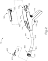
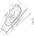
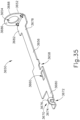
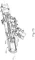
- FIGS. 1-2 depict an exemplary surgical circular stapling instrument (10) that may be used to provide an end-to-end, side-to-side, or end-to-side anastomosis between two sections of an anatomical lumen such as a portion of a patient's digestive tract.
- Instrument (10) of this example comprises a handle assembly (100), a shaft assembly (200), a stapling head assembly (300), and an anvil (400).
- Handle assembly (100) comprises a casing (110) defining an obliquely oriented pistol grip (112).
- pistol grip (112) is perpendicularly oriented.
- pistol grip (112) is omitted.
- Handle assembly (100) further includes a user feedback feature (114) that permits viewing of a movable indicator needle (1526) as will be described in greater detail below.
- a series of hash marks, colored regions, and/or other fixed indicators are positioned adjacent to user feedback feature (114) in order to provide a visual context for indicator needle (1526), thereby facilitating operator evaluation of the position of needle (1526) within user feedback feature (114).
- Various suitable alternative features and configurations for handle assembly (100) will be apparent to those of ordinary skill in the art in view of the teachings herein.
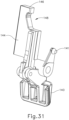
- Instrument (10) of the present example further includes a battery pack (120).
- Battery pack (120) is operable to provide electrical power to a motor (161) in pistol grip (112) as will be described in greater detail below.
- Battery pack (120) is removable from handle assembly (100).
- battery pack (120) may be inserted into a socket (116) defined by casing (110). Once battery pack (120) is fully inserted in socket (116), latches (122) of battery pack (120) may resiliently engage interior features of casing (110) to provide a snap fit.
- battery pack (120) may have complementary electrical contacts, pins and sockets, and/or other features that provide paths for electrical communication from battery pack (120) to electrically powered components in handle assembly (100) when battery pack (120) is inserted in socket (116). It should also be understood that, in some versions, battery pack (120) is unitarily incorporated within handle assembly (100) such that battery pack (120) cannot be removed from handle assembly (100).
- Shaft assembly (200) extends distally from handle assembly (100) and includes a preformed bend.
- the preformed bend is configured to facilitate positioning of stapling head assembly (300) within a patient's colon.
- shaft assembly (200) is straight, such that shaft assembly (200) lacks a preformed bend.
- Various exemplary components that may be incorporated into shaft assembly (200) will be described in greater detail below.
- Stapling head assembly (300) is located at the distal end of shaft assembly (200). As shown in FIGS. 1-2 and as will be described in greater detail below, anvil (400) is configured to removably couple with shaft assembly (200), adjacent to stapling head assembly (300). As will also be described in greater detail below, anvil (400) and stapling head assembly (300) are configured to cooperate to manipulate tissue in three ways, including clamping the tissue, cutting the tissue, and stapling the tissue.
- a knob (130) at the proximal end of handle assembly (100) is rotatable relative to casing (110) to provide precise clamping of the tissue between anvil (400) and stapling head assembly (300). When a safety trigger (140) of handle assembly (100) is pivoted away from a firing trigger (150) of handle assembly (100), firing trigger (150) may be actuated to thereby provide cutting and stapling of the tissue.
- distal and proximal will be used with reference to the orientation of anvil (400) when anvil (400) is coupled with shaft assembly (200) of instrument (10).
- proximal features of anvil (400) will be closer to the operator of instrument (10); while distal features of anvil (400) will be further from the operator of instrument (10).
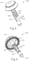
- anvil (400) of the present example comprises a head (410) and a shank (420).
- Head (410) includes a proximal surface (412) that defines a plurality of staple forming pockets (414).
- Staple forming pockets (414) are arranged in two concentric annular arrays in the present example.
- staple forming pockets (414) are arranged in three or more concentric annular arrays.
- Staple forming pockets (414) are configured to deform staples as the staples are driven into staple forming pockets (414). For instance, each staple forming pocket (414) may deform a generally "U" shaped staple into a "B" shape as is known in the art.
- proximal surface (412) terminates at an inner edge (416), which defines an outer boundary of an annular recess (418) surrounding shank (420).
- Shank (420) defines a bore (422) and includes a pair of pivoting latch members (430) positioned in bore (422).
- each latch member (430) includes a "T" shaped distal end (432), a rounded proximal end (434), and a latch shelf (436) located distal to proximal end (434).
- "T" shaped distal ends (432) secure latch members (430) within bore (422).
- Latch members (430) are positioned within bore (422) such that proximal ends (434) are positioned at the proximal ends of lateral openings (424), which are formed through the sidewall of shank (420).
- Lateral openings (424) thus provide clearance for proximal ends (434) and latch shelves (436) to deflect radially outwardly from the longitudinal axis defined by shank (420).
- latch members (430) are configured to resiliently bias proximal ends (434) and latch shelves (436) to pivot radially inwardly toward the longitudinal axis defined by shank (420).
- Latch members (430) thus act as retaining clips. This allows anvil (400) to be removably secured to a trocar (330) of stapling head assembly (300) as will be described in greater detail below.
- latch members (430) When shank (420) is secured to trocar (330) and trocar (330) is retracted proximally, the inner diameter of bore (314) in inner core member (312) of body member (310) laterally constrains latch members (430) to maintain engagement between latch shelves (436) and proximal surface (338) of head (334) of trocar (330). This engagement prevents anvil (400) from being released from trocar (330) during firing of stapling head assembly (300). It should be understood, however, that latch shelves (436) are merely optional. Anvil (400) may be removably secured to a trocar (330) using any other suitable components, features, or techniques.
- shank (420) of the present example includes a set of longitudinally extending splines (426) that are spaced about shank (420) in an angular array.
- the proximal end of each spline (426) includes a respective lead-in edge (428).
- splines (426) are configured to engage corresponding splines (316) of an inner body member (310) of stapling head assembly (300) in order to consistently provide a predetermined angular alignment between anvil (400) and stapling head assembly (300).
- this angular alignment may ensure that staple forming pockets (414) of anvil (400) are consistently angularly aligned appropriately with staple openings (324) of stapling head assembly (300).
- splines (426) are precisely and consistently positioned in relation to staple forming pockets (414).
- the machine or other device that is used to join head (410) and shank (420) together may have appropriate indexing capabilities in order to reliably and consistently achieve the proper angular positioning of head (410) and shank (420) to thereby provide precise and consistent positioning of splines (426) in relation to staple forming pockets (414).
- head (410) and shank (420) are formed together simultaneously, as a single unitary construction.
- reconfiguring and rearranging staple forming pockets (414) may result in reconfiguration and rearrangement of staples (90) that are formed by staple forming pockets (414).
- the configuration and arrangement of staple forming pockets (414) may affect the structural integrity of an anastomosis (70) that is secured by staples (90).
- the configuration and arrangement of staple forming pockets (414) may affect the hemostasis that is achieved at an anastomosis (70) that is secured by staples (90).
- the following description relates to several exemplary variations of anvil (400), providing staple forming pocket configurations and arrangements that differ from those of staple forming pockets (414).
- FIGS. 6-8 show an exemplary alternative anvil (500) that may be used with a modified version of instrument (10).
- Anvil (500) of this example is configured and operable just like anvil (400), except for the differences described below.
- Anvil (500) of the present example comprises a proximal surface (506) that defines an inner annular array (502) of staple forming pockets (510, 530) and an outer annular array (504) of staple forming pockets (550, 570).
- a chamfered edge (508) extends about the outer perimeter of proximal surface (506).
- anvil (500) may be secured to trocar (330), that proximal surface (506) may be used to compress tissue against deck surface (322), and that staple driver (352) may drive staples (90) through tissue into staple forming pockets (510, 530, 550, 570) in order to thereby form staples (90) in the tissue.
- each staple forming pocket (510) comprises a staple entry surface (512) and a staple exit surface (514).
- Surfaces (512, 514) are contiguous with each other and define a concave recess.
- the concave recess formed by surfaces (512, 514) is further defined by an inner wall (516), a first outer wall (518), a second outer wall (520), and a third outer wall (522).
- walls (516, 518, 520, 522) are each substantially flat.
- Wall (518) defines a relatively narrow, tapered gap with wall (516).
- Wall (522) defines a relatively wide gap with wall (516).
- Wall (520) is obliquely angled, providing an inwardly sloped transition from wall (522) to wall (518).
- walls (518, 520, 522) together provide a dogleg configuration.
- the edge connecting wall (516) with wall (522) is substantially straight in this example.
- the edge connecting wall (516) with wall (518) is substantially straight in this example.
- first leg of staple (90) when a first leg of staple (90) is driven into staple forming pocket (510), the first leg first encounters staple entry surface (512), bends generally toward the second leg of staple (90) along a first plane that is orthogonal to the axis of the unformed first leg, and then bends proximally back generally toward the crown of staple (90).
- first leg will eventually encounter wall (520), which will provide a cam surface bending the first leg along a second plane that is orthogonal to the axis of the unformed first leg.
- wall (520) and then wall (518) will deflect the first leg radially inwardly toward the central axis of anvil (500).
- staple forming pocket (510) will ultimately deflect a first leg of a staple (90) proximally and radially inwardly.
- Wall (516) will restrict the degree to which the first leg of staple (90) deflects radially inwardly.
- Each staple forming pocket (530) comprises a staple entry surface (532) and a staple exit surface (534).
- Surfaces (532, 534) are contiguous with each other and define a concave recess.
- the concave recess formed by surfaces (532, 534) is further defined by an outer wall (536), a first inner wall (538), a second inner wall (540), and a third inner wall (542).
- walls (536, 538, 540, 542) are each substantially flat.
- Wall (538) defines a relatively narrow, tapered gap with wall (536).
- Wall (542) defines a relatively wide gap with wall (536).
- Wall (540) is obliquely angled, providing an outwardly sloped transition from wall (542) to wall (538).
- walls (538, 540, 542) together provide a dogleg configuration.
- the edge connecting wall (536) with wall (542) is substantially straight in this example.
- the edge connecting wall (536) with wall (538) is substantially straight in this example
- a second leg of staple (90) when a second leg of staple (90) is driven into staple forming pocket (530), the second leg first encounters staple entry surface (532), bends generally toward the first leg of staple (90) along a first plane that is orthogonal to the axis of the unformed second leg, and then bends proximally back generally toward the crown of staple (90).
- the second leg will eventually encounter wall (540), which will provide a cam surface bending the second leg along a second plane that is orthogonal to the axis of the unformed second leg.
- wall (540) and then wall (538) will deflect the second leg radially outwardly away from the central axis of anvil (500).
- staple forming pocket (530) will ultimately deflect a second leg of a staple (90) proximally and radially outwardly.
- Wall (536) will restrict the degree to which the second leg of staple (90) deflects radially outwardly.
- Each staple forming pocket (550) comprises a staple entry surface (552) and a staple exit surface (554).
- Surfaces (552, 554) are contiguous with each other and define a concave recess.
- the concave recess formed by surfaces (552, 554) is further defined by an outer wall (556), a first inner wall (558), a second inner wall (560), and a third inner wall (562).
- walls (556, 558, 560, 562) are each substantially flat.
- Wall (558) defines a relatively narrow, tapered gap with wall (556).
- Wall (562) defines a relatively wide gap with wall (556).
- Wall (560) is obliquely angled, providing an outwardly sloped transition from wall (562) to wall (558).
- walls (558, 560, 562) together provide a dogleg configuration.
- the edge connecting wall (556) with wall (562) is substantially straight in this example.
- the edge connecting wall (556) with wall (558) is substantially straight in this example
- a second leg of staple (90) when driven into staple forming pocket (550), the second leg first encounters staple entry surface (552), bends generally toward the first leg of staple (90) along a first plane that is orthogonal to the axis of the unformed second leg, and then bends proximally back generally toward the crown of staple (90).
- the second leg will eventually encounter wall (560), which will provide a cam surface bending the second leg along a second plane that is orthogonal to the axis of the unformed second leg.
- wall (560) and then wall (558) will deflect the second leg radially outwardly away from the central axis of anvil (500).
- staple forming pocket (550) will ultimately deflect a second leg of a staple (90) proximally and radially outwardly.
- Wall (556) will restrict the degree to which the second leg of staple (90) deflects radially outwardly.
- Each staple forming pocket (570) comprises a staple entry surface (572) and a staple exit surface (574).
- Surfaces (572, 574) are contiguous with each other and define a concave recess.
- the concave recess formed by surfaces (572, 574) is further defined by an inner wall (576), a first outer wall (578), a second outer wall (580), and a third outer wall (582).
- walls (576, 578, 580, 582) are each substantially flat.
- Wall (578) defines a relatively narrow, tapered gap with wall (576).
- Wall (582) defines a relatively wide gap with wall (576).
- Wall (580) is obliquely angled, providing an inwardly sloped transition from wall (582) to wall (578).
- walls (578, 580, 582) together provide a dogleg configuration.
- the edge connecting wall (576) with wall (582) is substantially straight in this example.
- the edge connecting wall (576) with wall (578) is substantially
- first leg of staple (90) when driven into staple forming pocket (570), the first leg first encounters staple entry surface (572), bends generally toward the second leg of staple (90) along a first plane that is orthogonal to the axis of the unformed first leg, and then bends proximally back generally toward the crown of staple (90).
- first leg will eventually encounter wall (580), which will provide a cam surface bending the first leg along a second plane that is orthogonal to the axis of the unformed first leg.
- wall (580) and then wall (578) will deflect the first leg radially inwardly toward the central axis of anvil (500).
- staple forming pocket (570) will ultimately deflect a first leg of a staple (90) proximally and radially inwardly.
- Wall (576) will restrict the degree to which the first leg of staple (90) deflects radially inwardly.
- staple forming pockets (510, 530, 550, 570) are arranged such that a radius line (R L ) extending outwardly from the center of anvil (500) passes through the region of staple entry surface (512) of staple forming pocket (510) and through the region of staple entry surface (552) of staple forming pocket (550).
- a radius line (R L ) extending outwardly from the center of anvil (500) passes through the region of staple entry surface (512) of staple forming pocket (510) and through the region of staple entry surface (552) of staple forming pocket (550).
- another radius line (R L ) extending outwardly from the center of anvil (500) passes through the region of staple entry surface (532) of staple forming pocket (530) and through the region of entry surface (572) of staple forming pocket (570).
- staple forming pockets (530, 570) overlap along a radial dimension.
- another radius line (R L ) extending outwardly from the center of anvil (500) passes through the region of exit surface (574) of staple forming pocket (570) and through the region of exit surface (554) of staple forming pocket (550).
- staple forming pockets (550, 570) overlap along a radial dimension. It should also be understood that staple forming pockets (550, 570) in each pair of pockets (550, 570) are interlocking in this configuration.
- FIG. 500 Another radius line (R L ) extending outwardly from the center of anvil (500) passes through the region of staple exit surface (514) of staple forming pocket (510) and through the region of exit surface (534) of staple forming pocket (530).
- staple forming pockets (510, 530) overlap along a radial dimension. It should also be understood that staple forming pockets (510, 530) in each pair of pockets (510, 530) are interlocking in this configuration.
- inner annular array (502) and outer annular array (504) are configured similarly, such that the inner-most pocket (510) in each pair of inner pockets (510, 530) is on the left-hand side (in the view of FIG. 7 ) of the pair of pockets (510, 530); and such that the inner-most pocket (570) in each pair of outer pockets (550, 570) is on the left-hand side (in the view of FIG. 7 ) of the pair of pockets (550, 570).
- the end of wall (536) associated with staple entry surface (532) includes a bent region (537), which bends slightly inwardly toward the central region of anvil (500). It should be understood that this bent region (537) may be formed in order to maintain a minimum distance between wall (536) and wall (576), thereby maintaining a minimum distance between staple forming pocket (530) and staple forming pocket (570), which may further provide more reliable manufacturing of anvil (500). In addition, bent region (537) may provide different behavior of the second leg of the staple (90) that is formed by staple forming pocket (530).
- Such different behavior may relate to deflections in anvil (500) and/or a tilt that might result in the first and second legs of a given staple (90) contacting corresponding surfaces (512, 532) at different times during actuation of stapling head assembly (300).
- bent region (537) provides staple forming pocket (530) with a structural configuration that makes staple forming pocket (530) unique relative to the other staple forming pockets (510, 550, 570).
- staple forming pocket (510) is identical to the structural configuration of staple forming pocket (570); while the structural configuration of staple forming pocket (550) is the mirrored inverse of the structural configuration of staple forming pockets (510, 570).
- the spacing between pockets (510, 530) in each pair of pockets (510, 530) is equal to the spacing between pockets (550, 570) in each pair of pockets (550, 570).
- staples (90) formed by pockets (510, 530) will have the same crown width as staples formed by pockets (550, 570).
- the spacing between pockets (510, 530) in each pair of pockets (510, 530) is smaller than the spacing between pockets (550, 570) in each pair of pockets (550, 570).
- pockets (550, 570) may be used to form staples (90) having a longer crown width than staples (90) that are formed using pockets (510, 530).
- the spacing between pockets (510, 530) in each pair of pockets (510, 530) may be larger than the spacing between pockets (550, 570) in each pair of pockets (550, 570).
- pockets (550, 570) may be used to form staples (90) having a shorter crown width than staples (90) that are formed using pockets (510, 530).
- staples (90) in one array may have a larger, smaller, or same crown width as staples (90) in another annular array.
- staple forming pockets (510, 530) are arranged such that they are not fully centered along a circumferential line (C L ) extending along surface (506) at a constant radius from the center of anvil (500).
- the outermost regions of staple entry surfaces (512, 532) are radially centered along the same circumferential line (C L ).
- staple forming pocket (510) is oriented substantially obliquely relative to circumferential line (C L ), such that staple exit surface (514) is positioned substantially radially inwardly from circumferential line (C L ).
- staple exit surface (534) is positioned substantially along, with a portion position slightly radially outwardly from, circumferential line (C L ).
- staple forming pocket (530) is substantially aligned along circumferential line (C L )
- staple forming pocket (510) is substantially tilted radially inwardly relative to circumferential line (C L ), with the outermost regions of staple entry surfaces (512, 532) being radially centered along a circumferential line (C L ).
- FIGS. 7-8 While the views depicted in FIGS. 7-8 only show a portion of the full circumference of anvil (500), it should be understood that the structures depicted in FIGS. 7-8 extend along the full circumference of anvil (500). The views of FIGS. 7-8 are simply being provided as an enlargement to show the structure in further detail, and are not intended to suggest that the depicted structures are only located in a limited angular range along the circumference of anvil (500).
- staples formed by anvil (500) will have a three-dimensional profile, where the legs are angularly offset from a plane passing through a crown of the staple; in addition to being bent generally toward each other.
- the staples formed using anvil (500) may have an appearance similar to at least some of the staples shown and described in U.S. Pat. No. 10,092,292 , entitled “Staple Forming Features for Surgical Stapling Instrument”.
- the staples formed using anvil (500) may have an appearance similar to at least some of the staples shown and described in U.S. Pub. No. 2018/0132849, entitled “Staple Forming Pocket Configurations for Circular Surgical Stapler Anvil,” published May 17, 2018 .
- anvil (400) may be further constructed and operable in accordance with at least some of the teachings of U.S. Pat. No. 5,205,459 ; U.S. Pat. No. 5,271,544 ; U.S. Pat. No. 5,275,322 ; U.S. Pat. No. 5,285,945 ; U.S. Pat. No. 5,292,053 ; U.S. Pat. No. 5,333,773 ; U.S. Pat. No. 5,350,104 ; U.S. Pat. No. 5,533,661 ; and/or U.S. Pat. No. 8,910,847 . Still other suitable configurations will be apparent to one of ordinary skill in the art in view of the teachings herein.
- stapling head assembly (300) of the present example is coupled to a distal end of shaft assembly (200) and comprises a body member (310) and a slidable staple driver member (350).
- Body member (310) includes a distally extending cylindraceous inner core member (312).
- Body member (310) is fixedly secured to an outer sheath (210) of shaft assembly (200).
- Body member (310) and outer sheath (210) thus serve together as a mechanical ground for stapling head assembly (300).
- inner core member (312) of body member (310) defines a bore (314).
- a plurality of longitudinally extending splines (316) are equidistantly spaced in an angular array within bore (314).
- the distal ends of splines (316) include lead-in edges (318) that are configured to complement lead-in edges (428) of splines (426) on shank (420) of anvil (400).
- lead-in edges (318, 428) may cooperatively engage each other to drive anvil (400) to rotate relative to trocar (330) to angularly align splines (426) of anvil (400) with the gaps between splines (316) of body member (310).
- the gaps between splines (316) may be configured to have a width that is substantially equal to the width of splines (426).
- anvil (400) may achieve a predetermined angular alignment relative to stapling head assembly (300). This predetermined angular alignment may ensure that staple openings (324) of deck member (320) are precisely aligned with corresponding staple forming pockets (414, 510, 530) of anvil (400).
- splines (316, 426) are configured to cooperate with each other to ensure that staples ejected through staple openings (324) are accurately driven into corresponding staple forming pockets (414, 510, 530) on a consistent basis, regardless of the angular orientation of anvil (400) relative to stapling head assembly (300) at the time anvil (400) is initially secured to trocar (330).
- Trocar (330) is positioned coaxially within inner core member (312) of body member (310). As will be described in greater detail below, trocar (330) is operable to translate distally and proximally relative to body member (310) in response to rotation of knob (130) relative to casing (110) of handle assembly (100).
- Trocar (330) comprises a shaft (332) and a head (334). Head (334) includes a pointed tip (336) and an inwardly extending proximal surface (338). Shaft (332) thus provides a reduced outer diameter just proximal to head (334), with proximal surface (338) providing a transition between that reduced outer diameter of shaft (332) and the outer diameter of head (334).
- tip (336) is pointed in the present example, tip (336) is not sharp. Tip (336) will thus not easily cause trauma to tissue due to inadvertent contact with tissue.
- Head (334) and the distal portion of shaft (332) are configured for insertion in bore (422) of anvil (400).
- Proximal surface (338) and latch shelves (436) have complementary positions and configurations such that latch shelves (436) engage proximal surface (338) when shank (420) of anvil (400) is fully seated on trocar (330). Anvil (400) is thus secured to trocar (330) through a snap fit due to latch members (430).
- Staple driver member (350) is operable to actuate longitudinally within body member (310) in response to activation of motor (161) as will be described in greater detail below.
- Staple driver member (350) includes two distally presented concentric annular arrays of staple drivers (352).
- Staple drivers (352) are arranged to correspond with the arrangement of staple forming pockets (414) described above.
- each staple driver (352) is configured to drive a corresponding staple into a corresponding staple forming pocket (414) when stapling head assembly (300) is actuated.
- the arrangement of staple drivers (352) may be modified just like the arrangement of staple forming pockets (414) as described above.
- Staple driver member (350) also defines a bore (354) that is configured to coaxially receive inner core member (312) of body member (310).
- An annular array of studs (356) project distally from a distally presented surface surrounding bore (354).
- Knife member (340) is coaxially positioned within staple driver member (350).
- Knife member (340) includes a distally presented, sharp circular cutting edge (342).
- Knife member (340) is sized such that knife member (340) defines an outer diameter that is smaller than the diameter defined by the inner annular array of staple drivers (352).
- Knife member (340) also defines an opening that is configured to coaxially receive inner core member (312) of body member (310).
- An annular array of openings (346) formed in knife member (340) is configured to complement the annular array of studs (356) of staple driver member (350), such that knife member (340) is fixedly secured to staple driver member (350) via studs (356) and openings (346).
- studs (356) may be heat staked to knife member (340) using techniques known in the art.
- Other suitable structural relationships between knife member (340) and staple driver member (350) will be apparent to those of ordinary skill in the art in view of the teachings herein.
- a deck member (320) is fixedly secured to body member (310).
- Deck member (320) includes a distally presented deck surface (322) defining two concentric annular arrays of staple openings (324).
- Staple openings (324) are arranged to correspond with the arrangement of staple drivers (352) and staple forming pockets (414) described above.
- each staple opening (324) is configured to provide a path for a corresponding staple driver (352) to drive a corresponding staple through deck member (320) and into a corresponding staple forming pocket (414) when stapling head assembly (300) is actuated.
- the arrangement of staple openings (324) may be modified just like the arrangement of staple forming pockets (414) as described above.
- deck member (320) defines an inner diameter that is just slightly larger than the outer diameter defined by knife member (340). Deck member (320) is thus configured to allow knife member (340) to translate distally to a point where cutting edge (342) is distal to deck surface (322).
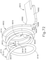
- FIGS. 12-13 show an example of a deck member (600) that provides enhanced tissue gripping effects without increasing the risk of tissue damage. Deck member (600) may be readily incorporated into stapling head assembly (300) in place of deck member (320).
- Deck member (600) of this example includes a first deck surface (622), a second deck surface (630), and two concentric annular arrays of staple openings (624). Staple openings (624) are arranged to correspond with the arrangement of staple drivers (352) and staple forming pockets (414) described above. Thus, each staple opening (624) is configured to provide a path for a corresponding staple driver (352) to drive a corresponding staple through deck member (600) and into a corresponding staple forming pocket (414) when a stapling head assembly (300) incorporating deck member (600) is actuated.
- Deck member (600) defines an inner diameter that is just slightly larger than the outer diameter defined by knife member (340). Deck member (600) is thus configured to allow knife member (340) to translate distally to a point where cutting edge (342) is distal to the plane of second deck surface (630).
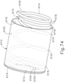
- an outer edge (620) spans around the full circumference of deck member (600) with a consistent surface geometry.
- outer edge (620) is configured to prevent outer edge (620) from snagging on tissue.
- outer edge (620) has a curved profile.
- outer edge (620) has a chamfered profile.
- outer edge (620) may have any other suitable kind of profile.
- Second deck surface (630) is proud relative to first deck surface (622), such that first deck surface (622) is recessed relative to second deck surface (630). As shown, second deck surface (630) fully surrounds each and every staple opening (624), including the inner array of staple openings (624) and the outer array of staple openings (624). However, first deck surface (622) extends inwardly between staple openings (624) of the outer array of staple openings (624), thereby creating gaps (626) in second deck surface (630) between staple openings (624) of the outer array of staple openings (624).
- a plurality of recesses (670) are spaced between the staple openings (624) of the inner annular array of staple openings (624).
- Recesses (670) of the present example are generally shaped like isosceles triangles, with each triangle being defined by a pair of straight walls (674) having equal length and an inner annular wall (672).
- the vertexes formed by walls (674) are positioned at the radially outermost points of recesses (670). In particular, these vertexes are located at radial positions corresponding to the same circumference at which the angularly outermost points of staple openings (624) are located.
- these vertexes of recesses (670) and corresponding points of staple openings (624) are all positioned at the same radial distance along the same circumference in this example.
- the position and configuration of recesses (670) may have any other suitable relationship with the position and configuration of staple openings (624).
- Recesses (670) of the present example are joined together by channels (680) which are defined between inner annular wall (672) and respective opposing annular walls (676). Walls (672, 676) are parallel with each other and are closely positioned relative to each other, such that channels (680) are substantially small in comparison to recesses (670).
- Gaps (626), recesses (670), and channels (680) are configured to receive tissue as tissue is being compressed against deck surfaces (622, 630) by anvil (400) as described above.
- anvil (400) is actuated via knob (130) to compress tissue between anvil (400) and deck surfaces (622, 630
- portions of the compressed tissue will enter gaps (626), recesses (670), and channels (680).
- this may reduce the total pressure that would otherwise be applied to the tissue if the tissue were being compressed against a consistently flat deck surface like deck surface (322). The pressure on tissue is thus concentrated only in the areas where pressure is actually needed-immediately adjacent to staple openings (624).
- deck member (600) may reduce the risk of the tissue from becoming fractured by over-compression.
- the entry of tissue portions in gaps (626), recesses (670), and channels (680) may provide a grip on the compressed tissue that is greater than the grip that could otherwise be achieved using a consistently flat deck surface like deck surface (322).
- the enhanced grip of tissue may promote cleaner cutting by knife member (340) and also promote more successful deployment of staples (90) in the tissue.
- the presence of gaps (626), recesses (670), and channels (680) may both reduce the risk of over-compression of tissue and promote greater success in cutting and stapling the tissue.
- gaps (626), recesses (670), and channels (680) all extend to substantially the same depth relative to second deck surface (630). In some other versions, gaps (626), recesses (670), and channels (680) extend to different depths relative to second deck surface (630). For instance, gaps (626) may extend to greater depths than recesses (670) relative to second deck surface (630) or vice versa. It should also be understood that gaps (626) may alternate depths relative to second deck surface (630), such that gaps (626) alternate between a relatively shallow gap (626) and a relatively deep gap (626) along at least a portion of the angular range of deck member (600).
- recesses (670) may alternate depths relative to second deck surface (630), such that recesses (670) alternate between a relatively shallow recess (670) and a relatively deep recess (670) along at least a portion of the angular range of deck member (600).
- the depth of a given gap (626) or recess (670) may vary within that particular gap (626) or recess (670). For instance, the radially innermost region of a given gap (626) may be deeper or shallower than the radially outermost region of that same gap (626).
- each recess (670) near the vertex may be deeper or shallower than the region of each recess (670) near inner annular wall (672).
- Other suitable variations that may be provided in the depth of gaps (626), recesses (670), and/or channels (680) relative to second deck surface (630) will be apparent to those of ordinary skill in the art in view of the teachings herein.
- Inner annular wall (672) extends consistently along the full circumference of deck member (600). In particular, the height of the uppermost edge of inner annular wall (672) is consistent along the full circumference of deck member (600). The uppermost edge of inner annular wall (672) is thus configured to provide consistent pressure against the adjacent annular region of tissue as the tissue is being compressed against deck member (600) by anvil (400). This application of consistent pressure against the adjacent annular region of tissue may further assist in clean cutting of the tissue by knife member (340), particularly since knife member (340) will be severing the tissue right next to the uppermost edge of inner annular wall (672).
- the uppermost edge of inner annular wall (672) is substantially flush with second deck surface (630). In some other variations, the uppermost edge of inner annular wall (672) is proud or raised relative to second deck surface (630). In still other variations, the uppermost edge of inner annular wall (672) is recessed or lower relative to second deck surface (630).
- instrument (10) it may desirable to provide instrument (10) with features that are configured to indicate proper and/or improper attachment of anvil (400) to trocar (330) of stapling head assembly (300). For instance, if anvil (400) is not properly attached to trocar (330), an operator may receive audible and/or tactile feedback indicating improper attachment. Additionally, if anvil (400) is properly attached to trocar (330), an operator may receive audible, tactile, and/or visible feedback indicating proper attachment. In addition or in the alternative, features may be configured to prevent firing of stapling head assembly (300) unless anvil (400) is properly attached to trocar (330).
- stapling head assembly (300) may be prevented from firing. If anvil (400) is properly attached to trocar (330), firing of stapling head assembly (300) may be enabled.
- Various examples of such features will be described in greater detail below; while other examples will be apparent to those of ordinary skill in the art in view of the teachings herein. Moreover, the following teachings may be applied to devices that are used in various other contexts.
- trocar (330) includes a colored region (333) that is longitudinally positioned at a location where colored region (333) is exposed before shank (420) is fully seated on trocar (330) ( FIG. 14A ); and covered when shank (420) is fully seated on trocar (330) ( FIG. 14B ).
- Colored region (333) may be colored using a color (e.g., orange) that is easily visible in relation to adjacent regions of trocar (330) and shank (420).
- the operator may observe colored region (333) to ensure that the entire colored region (333) is obscured by shank (420) before attempting to retract the combination of trocar (330) and anvil (400) relative to stapling head assembly (300). If the operator continues to see even a portion of colored region (333), the operator may continue pressing anvil (400) onto trocar (330) until colored region (333) is completely obscured by shank (420).
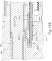
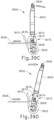
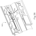
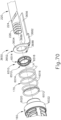
- FIGS. 15A-16B depict an exemplary switch assembly (2600) that is incorporated into stapling head assembly (300) in the present example.
- Switch assembly (2600) includes a dome switch (2610) and a resilient actuator spring (2602).
- Actuator spring (2602) is secured within a cavity (2606) formed within body member (310).
- Dome switch (2610) is positioned between a pair of flanges (2612, 2614) of actuator spring (2602) such that movement of flange (2612) toward flange (2614) will actuate dome switch (2610).
- dome switch (2610) may provide audible, tactile, and/or visible feedback to an operator indicating proper attachment.
- actuation of dome switch (2610) may enables firing of stapling head assembly (300). In other words, unless dome switch (2610) has been actuated, stapling head assembly (300) may not be fired in the present example.
- trocar (330) After anvil (400) is secured to trocar (330), the operator then rotates knob (130) to cause trocar (330) and anvil (400) to retract proximally as described above.
- knob (130) When trocar (330) and anvil (400) are properly secured to one another, the proximal retraction of trocar (330) and anvil (400) compresses the tissue of tubular anatomical structures (20, 40) between surfaces (412, 322) of anvil (400) and stapling head assembly (300) as described herein.
- trocar (330) and anvil (400) When trocar (330) and anvil (400) are not properly secured to one another, trocar (330) is retracted proximally without anvil (400), such that the tissue of tubular anatomical structures (20, 40) remains uncompressed.
- dome switch (2610) is not actuated immediately upon proper seating of shank (420) on trocar (330). Instead, trocar (330) and anvil (400) have to be retracted proximally relative to stapling head assembly (300) by at least some distance before dome switch (2610) is actuated. In the present example, dome switch (2610) is actuated before anvil (400) reaches the "green zone” as described herein. In some other variations, dome switch (2610) is not actuated until after anvil (400) reaches the distal-most boundary of the "green zone" as described herein.
- dome switch (2610) may provide audible, tactile, and/or visible feedback to an operator indicating proper attachment. Moreover, such actuation of dome switch (2610) enables firing of stapling head assembly (300). In other words, unless dome switch (2610) has been actuated, stapling head assembly (300) may not be fired.
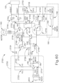
- An exemplary way in which dome switch (2610) may be integrated into a control circuit (2700) will be described in greater detail below with reference to FIG. 60 . Other examples will be apparent to those of ordinary skill in the art in view of the teachings herein.
- stapling head assembly (300) may be further constructed and operable in accordance with at least some of the teachings of U.S. Pat. No. 5,205,459 ; U.S. Pat. No. 5,271,544 ; U.S. Pat. No. 5,275,322 ; U.S. Pat. No. 5,285,945 ; U.S. Pat. No. 5,292,053 ; U.S. Pat. No. 5,333,773 ; U.S. Pat. No. 5,350,104 ; U.S. Pat. No. 5,533,661 ; and/or U.S. Pat. No. 8,910,847 . Still other suitable configurations will be apparent to one of ordinary skill in the art in view of the teachings herein.
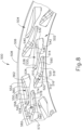
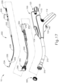
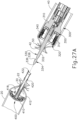
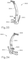
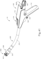
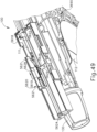
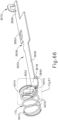
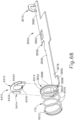
- FIG. 17 shows various components of shaft assembly (200), which couples components of stapling head assembly (300) with components of handle assembly (100).
- shaft assembly (200) includes an outer sheath (210) that extends between handle assembly (100) and body member (310).
- outer sheath (210) is rigid and includes a preformed curved section as noted above.
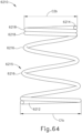
- Shaft assembly (200) further includes a trocar actuation rod (220) and a trocar actuation band assembly (230).
- the distal end of trocar actuation band assembly (230) is fixedly secured to the proximal end of shaft (332) of trocar (330).
- the proximal end of trocar actuation band assembly (230) is fixedly secured to the distal end of trocar actuation rod (220). It should therefore be understood that trocar (330) will translate longitudinally relative to outer sheath (210) in response to translation of trocar actuation band assembly (230) and trocar actuation rod (220) relative to outer sheath (210).
- Trocar actuation band assembly (230) is configured to flex such that trocar actuation band assembly (230) may follow along the preformed curve in shaft assembly (200) as trocar actuation band assembly (230) is translated longitudinally relative to outer sheath (210).
- trocar actuation band assembly (230) has sufficient column strength and tensile strength to transfer distal and proximal forces from trocar actuation rod (220) to shaft (332) of trocar (330).
- Trocar actuation rod (220) is rigid.
- a clip (222) is fixedly secured to trocar actuation rod (220) and is configured to cooperate with complementary features within handle assembly (100) to prevent trocar actuation rod (220) from rotating within handle assembly (100) while still permitting trocar actuation rod (220) to translate longitudinally within handle assembly (100).
- Trocar actuation rod (220) further includes a coarse helical threading (224) and a fine helical threading (226). Details regarding the movement of trocar actuation rod (220) will be described in greater detail below.
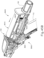
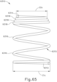
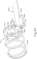
- Shaft assembly (200) further includes a stapling head assembly driver (240) that is slidably received within outer sheath (210).
- the distal end of stapling head assembly driver (240) is fixedly secured to the proximal end of staple driver member (350).
- the proximal end of stapling head assembly driver (240) is secured to a drive bracket (250) via a pin (242). It should therefore be understood that staple driver member (350) will translate longitudinally relative to outer sheath (210) in response to translation of stapling head assembly driver (240) and drive bracket (250) relative to outer sheath (210).
- Stapling head assembly driver (240) is configured to flex such that stapling head assembly driver (240) may follow along the preformed curve in shaft assembly (200) as stapling head assembly driver (240) is translated longitudinally relative to outer sheath (210).
- stapling head assembly driver (240) has sufficient column strength to transfer distal forces from drive bracket (250) to staple driver member (350). Details regarding the movement of drive bracket (250) will be described in greater detail below.
- shaft assembly (200) may further include one or more spacer elements within outer sheath (210).
- spacer elements may be configured to support trocar actuation band assembly (230) and/or stapling head assembly driver (240) as trocar actuation band assembly (230) and/or stapling head assembly driver (240) translate through outer sheath (210).
- spacer elements may prevent trocar actuation band assembly (230) and/or stapling head assembly driver (240) from buckling as trocar actuation band assembly (230) and/or stapling head assembly driver (240) translate through outer sheath (210).
- Various suitable forms that such spacer elements may take will be apparent to those of ordinary skill in the art in view of the teachings herein.
- handle assembly (100) includes several components that are operable to actuate anvil (400) and stapling head assembly (300). Handle assembly (100) also includes components that are operable to selectively lock out triggers (140, 150) based on the position of anvil (400) relative to stapling head assembly (300). When triggers (140, 150) are locked out, firing trigger (150) is prevented from initiating actuation of stapling head assembly (300). Thus, firing trigger (150) is only operable to initiate actuation of stapling head assembly (300) when the position of anvil (400) relative to stapling head assembly (300) is within a predefined range.
- the components of handle assembly (100) that provide the foregoing operability will be described in greater detail below.
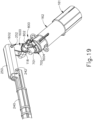
- Knob (130) protrudes proximally from casing (110) of handle assembly and is rotatable relative to casing (110). As shown in FIG. 19 , a nut (160) is secured to the distal end of knob (130). In the present example, nut (160) is fixedly secured to the distal end of knob (130) such that nut (160) will rotate unitarily with knob (130). Nut (160) and knob (130) are configured to cooperate with trocar actuation rod (220) to thereby translate trocar actuation rod (220) longitudinally relative to casing (110) in response to rotation of nut (160) and knob (130) relative to casing (110). As noted above, trocar (330) will translate longitudinally relative to outer sheath (210) in response to translation of trocar actuation rod (220) relative to outer sheath (210) and casing (110).
- trocar actuation rod (220) is positioned within handle assembly (100) to engage nut (160) and knob (130).
- trocar actuation rod (220) is positioned within handle assembly (100) such that coarse helical threading (224) will selectively engage a thread engagement feature (not shown) within the interior of nut (160); and such that fine helical threading (226) will selectively engage a thread engagement feature (not shown) within the interior of knob (130).
- the thread engagement feature of nut (160) comprises an inwardly directed tab; while the thread engagement feature of knob (130) comprises a helical threading.
- Other suitable forms that such thread engagement features may take will be apparent to those of ordinary skill in the art in view of the teachings herein.
- trocar actuation rod (220) travels proximally through a first range of longitudinal motion where coarse helical threading (224) is engaged with nut (160) to provide a relatively rapid rate of translation. Fine helical threading (226) is not engaged with knob (130) during this range of motion.
- trocar actuation rod (220) will continue to travel proximally through a second range of longitudinal motion where fine helical threading (226) is engaged with knob (130) to provide a relatively slow rate of translation.
- trocar actuation rod (220) will translate proximally through a sequence of rapid translation followed by slow translation, based on engagement between coarse helical threading (224) and nut (160) followed by engagement between fine helical threading (226) and knob (130).
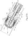
- knob (130) when anvil (400) is coupled with trocar (330), rotation of knob (130) will provide corresponding translation of anvil relative to stapling head assembly (300). It should also be understood that knob (130) may be rotated in a first angular direction (e.g., clockwise) to retract anvil (400) toward stapling head assembly (300); and in a second angular direction (e.g., counterclockwise) to advance anvil (400) away from stapling head assembly (300). Knob (130) may thus be used to adjust the gap distance (d) between opposing surfaces (412, 322) of anvil (400) and stapling head assembly (300) until a suitable gap distance (d) has been achieved as shown in FIG. 27C and as described in greater detail below.
- first angular direction e.g., clockwise
- a second angular direction e.g., counterclockwise
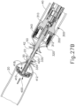
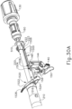
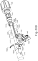
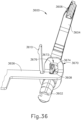
- FIGS. 19-26D show various components that are operable to actuate stapling head assembly (300). These components include motor (161), a gearbox (162), a rotary cam member (700), a cam follower (1600), drive bracket (250) and stapling head assembly driver (240). Gearbox (162) is coupled with a drive shaft of motor (161) and is further coupled with cam member (700). Activation of motor (161) thus causes rotation of cam member (700) via gearbox (162).
- gearbox (162) may comprise a multi-stage planetary gearbox.
- gearbox (162) may comprise a multi-stage planetary gearbox.
- Cam member (700) is configured to interact with cam follower (1600) to pivot cam follower (1600) in two angular directions about a pin (118) as will be described in greater detail below.
- Pin (118) is coupled with a chassis (e.g., chassis (3690) described below that as shown includes left and right chassis portions (3691, 3693)), which is located within casing (110).
- a bushing (701) provides rotary support to cam member (700) relative to the chassis in casing (110).
- Cam follower (1600) is pivotably coupled with drive bracket (250) via a pair of integral pins (1602), which are received in complementary notches (252) of drive bracket (250). As shown in FIGS. 20-21 , cam follower (1600) includes a first bearing feature (1604) and a second bearing feature (1610).
- First bearing feature (1604) consists of a rounded, horizontally extending surface.
- Second bearing feature (1610) is shaped like a quarter-pie defined by a straight vertical surface (1612), a horizontally extending surface (1614), and a curved surface (1616). Second bearing feature (1610) projects proximally relative to first bearing feature (1604).
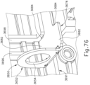
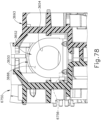
- FIGS. 22-23 show cam member (700) in greater detail.
- Cam member (700) comprises a distal face (702), a distally projecting post (704), and an outer circumferential surface (706).
- a first cam feature (710) and a second cam feature (720) project distally from distal face (702).
- Post (704) engages bushing (701).
- First cam feature (710) comprises a first surface region (712), a second surface region (714), and a third surface region (716).
- First surface region (712) is convexly defined by a relatively large radius of curvature, such that first surface region (712) is nearly flat.
- Second surface region (714) is convexly defined by a progressively increasing radius of curvature.
- Third surface region (716) is concavely defined by a relatively large radius of curvature.
- second cam feature (720) projects outwardly from outer circumferential surface (706).
- Second cam feature (720) includes a first surface region (722) and a second surface region (724).
- First surface region (722) is substantially flat while second surface region (724) is concavely curved.
- the origin of the radius of curvature for each curved surface region (712, 714, 716, 724) is offset from the center of post (704).
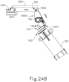
- FIGS. 24A-24B show the general interaction between cam follower (1600) and first and second cam features (710, 720), though this interaction will be described in greater detail below with reference to FIGS. 14A -14D.
- first cam feature (710) bears against first bearing feature (1604) of cam follower (1600), causing cam follower to pivot about pin (118).
- cam follower (1600) pivots counterclockwise as cam member (700) is rotated from the position shown in FIG. 24A to the position shown in FIG. 24B .
- cam follower (1600) drives drive bracket (250) and stapling head assembly driver (240) distally, thereby actuating stapling head assembly (300).
- cam member (700) continues to rotate in the same direction back toward the position shown in FIG. 24A
- second cam feature (720) engages and bears against second bearing feature (1610) of cam follower (1600), causing cam follower (1600) to pivot clockwise about pin (118).
- This clockwise pivoting of cam follower (1600) about pin (118) retracts drive bracket (250) and stapling head assembly driver (240) proximally back toward the position shown in FIG. 24A .
- a third cam feature (730) projects outwardly from outer circumferential surface (706).
- Third cam feature (730) comprises a first surface region (732) and a second surface region (734).
- First surface region (732) is flat and is oriented generally tangentially relative to outer circumferential surface (706).
- Second surface region (732) is also flat and is oriented radially outwardly relative to outer circumferential surface (706).
- Third cam feature (730) is configured to interact with a rocker member (800).
- Rocker member (800) comprises an integral pin (802), a bearing member (804), and a paddle (806).
- Pin (802) is pivotably coupled with the chassis in casing (110), such that rocker member (800) is pivotable within casing (110) about the longitudinal axis defined by pin (802).
- Bearing member (804) is configured to interact with third cam feature (730) as will be described in greater detail below.
- Paddle (806) is configured to actuate a switch buttons (192) of a motor stop module (190) as will also be described in greater detail below.
- FIG. 25A shows cam member (700) in the same position as shown in FIG. 24A .
- second surface region (734) of third cam feature (730) is adjacent to bearing member (804) of rocker member (800).
- FIG. 25B shows cam member (700) in a position where cam member (700) has been rotated past the position shown in FIG. 24B and back toward the position shown in FIG. 24A .
- cam member (700) has not completed a full revolution.
- first surface region (732) has engaged and borne against bearing member (804), thereby pivoting rocker member (800) about the longitudinal axis defined by pin (802). This has caused paddle (806) to actuate switch buttons (192) of motor stop module (190).
- Motor stop module (190) reverses the polarity of electrical power provided to motor (161) when switch buttons (192) are actuated. This results in stopping activation of motor (161) once an actuation stroke of stapling head assembly (300) has been completed.
- motor stop module (190) may be configured and operable in accordance with at least some of the teachings of U.S. Pat. No. 9,907,552, issued March 6, 2018 . Other suitable configurations will be apparent to those of ordinary skill in the art in view of the teachings herein.
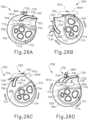
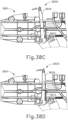
- FIGS. 26A-26D schematically depict the interaction between cam member (700), features of cam follower (1600), and features of rocker member (800) as cam member (700) rotates. It should be understood that the rotation of cam member (700) throughout the stages shown in FIGS. 26A-26D is driven by motor (161) and gearbox (162).
- FIG. 26A shows cam member (700) in the same position as shown in FIGS. 24A and 25A .
- first bearing feature (1604) of cam follower (1600) is positioned on first surface region (712) and bearing member (804) or rocker member (800) is adjacent to second surface region (734) of third cam feature (730).
- knife member (340) and staple driver member (350) are in proximal positions, such that stapling head assembly (300) is in a non-actuated state.
- cam member (700) is rotated to the position shown in FIG. 26B , second surface region (714) bears against bearing member (1604), thereby driving bearing member (1604) upwardly.
- cam follower (1600) to pivot about pin (118) to the position shown in FIG. 24B .
- Cam follower (1600) thus drives knife member (340) and staple driver member (350) distally via drive bracket (250) and stapling head assembly driver (240).
- Stapling head assembly (300) is thus in an actuated state at the stage shown in FIG. 26B .
- cam member (700) rotates through an angular range of approximately 270° in order to transition stapling head assembly (300) from the non-actuated state to the actuated state.
- cam member (700) continues to rotate to the position shown in FIG. 26C .
- first surface region (722) of second cam member (720) begins to engage curved surface (1616) of second bearing feature (1610) of cam follower (1600).
- second surface region (724) engages curved surface (1616) of second bearing feature (1610), driving second bearing feature (1610) downwardly. This causes cam follower (1600) to pivot about pin (118) back from the position shown in FIG. 24B toward the position shown in FIG. 24A .
- Cam follower (1600) thus drives knife member (340) and staple driver member (350) proximally via drive bracket (250) and stapling head assembly driver (240).
- first surface region (732) has engaged and borne against bearing member (804), thereby pivoting rocker member (800) about the longitudinal axis defined by pin (802) at the stage shown in FIG. 26D .
- Rocker member (800) is thus in the same state in FIG. 26D as shown in FIG. 25B .
- Motor stop module (190) has thus been actuated at the stage shown in FIG. 26D .
- cam member (700) is operable to drive knife member (340) and staple driver member (350) distally, then drive knife member (340) and staple driver member (350) proximally and actuate motor stop module (190) by rotating in a single angular direction through the range of motion shown in FIGS. 26A-26D .
- cam member (700) provides the full operational sequence depicted in FIGS. 26A-26D and described above by rotating through an angular range of motion of approximately 355°.
- the first 270° of rotation of cam member (700) may provide the distal movement of knife member (340) and staple driver member (350); while the remaining 85° of rotation of cam member (700) may provide the proximal movement of knife member (340) and staple driver member (350) and the actuation of motor stop module (190).
- Other suitable ways in which knife member (340), staple driver member (350), and motor stop module (190) may be actuated will be apparent to those of ordinary skill in the art in view of the teachings herein.
- FIGS. 27A-27E show instrument (10) being used to form an anastomosis (70) between two tubular anatomical structures (20, 40).
- the tubular anatomical structures (20, 40) may comprise sections of a patient's esophagus, sections of a patient's colon, other sections of the patient's digestive tract, or any other tubular anatomical structures.
- anvil (400) is positioned in one tubular anatomical structure (20) and stapling head assembly (300) is positioned in another tubular anatomical structure (40).
- tubular anatomical structures (20, 40) comprise sections of a patient's colon
- stapling head assembly (300) may be inserted via the patient's rectum.
- FIGS. 27A-27E the procedure depicted in FIGS. 27A-27E is an open surgical procedure, though the procedure may instead be performed laparoscopically.
- instrument (10) may be used to form an anastomosis (70) in a laparoscopic procedure will be apparent to those of ordinary skill in the art in view of the teachings herein.
- anvil (400) is positioned in tubular anatomical structure (20) such that shank (420) protrudes from the open severed end (22) of tubular anatomical structure (20).
- purse-string suture (30) is provided about a mid-region of shank (420) to generally secure the position of anvil (400) in tubular anatomical structure (20).
- purse-string suture (30) is tightened around the proximal end of shank (420).
- the proximal end of shank (420) may include a notch or other feature to securely capture purse-string suture (30).
- stapling head assembly (300) is positioned in tubular anatomical structure (40) such that trocar (330) protrudes from the open severed end (42) of tubular anatomical structure (20).
- a purse-string suture (50) is provided about a mid-region of shaft (332) to generally secure the position of stapling head assembly (300) in tubular anatomical structure (40).
- Stapling head assembly (300) is then urged distally to ensure that stapling head assembly (300) is fully seated at the distal end of tubular anatomical structure (40).
- anvil (400) is secured to trocar (330) by inserting trocar (330) into bore (422) as shown in FIG. 27B .
- Latch members (430) engage head (334) of trocar (330), thereby providing a secure fit between anvil (400) and trocar (330).
- the operator then rotates knob (130) while holding casing (110) stationary via pistol grip (112). This rotation of knob (130) causes trocar (330) and anvil (400) to retract proximally. As shown in FIG. 27C , this proximal retraction of trocar (330) and anvil (400) compresses the tissue of tubular anatomical structures (20, 40) between surfaces (412, 322) of anvil (400) and stapling head assembly (300).
- knob (130) may observe the tactile resistance or feedback via knob (130) while turning knob (130), with such tactile resistance or feedback indicating that the tissue is being compressed.
- the operator may visually observe the position of needle (1526) within user feedback feature (114) to determine whether the gap distance (d) between opposing surfaces (412, 322) of anvil (400) and stapling head assembly (300) is appropriate; and make any necessary adjustments via knob (130).
- anvil (400) of the present example includes a breakable washer (417) within annular recess (418).
- This washer (417) is broken by knife member (340) when the knife member (340) completes a full distal range of motion from the position shown in FIG. 27C to the position shown in FIG. 27D .
- the progressively increasing radius of curvature of second surface region may provide an increasing mechanical advantage as knife member (340) reaches the end of its distal movement, thereby providing greater force by which to break the washer (417).
- the breakable washer (417) may be omitted entirely in some versions. In versions where washer (417) is included, it should be understood that washer (417) may also serve as a cutting board for knife member (340) to assist in cutting of tissue.
- staple driver member (350) drives staples (90) through the tissue of tubular anatomical structures (20, 40) and into staple forming pockets (414) of anvil (400). Staple forming pockets (414) deform the driven staples (90) into a "B" shape as is known in the art; or into a three-dimensional shape as described above with respect to anvil (500). In either case, the formed staples (90) secure the ends of tissue together.
- instrument (10) may be removed via the patient's rectum.
- tubular anatomical structures (20, 40) With instrument (10) is removed, the tubular anatomical structures (20, 40) are left secured together by two annular arrays of staples (90) at an anastomosis (70) as shown in FIG. 27E .
- the inner diameter of the anastomosis (70) is defined by the severed edge (60) left by knife member (340).
- knob (130) may be used to adjust the gap distance (d) between opposing surfaces (412, 322) of anvil (400) and stapling head assembly (300). Setting an appropriate gap distance (d) before actuating stapling head assembly (300) may be critical to the success of an anastomosis. For instance, if the gap distance (d) is too great, the staples that are deployed at the anastomosis site may not be sufficiently formed by staple forming pockets (414). This may result in leakage at the anastomosis site, and in some cases may ultimately lead to the separation of the anatomical lumen sections that are joined at the anastomosis site.
- the gap distance (d) is too small, the internal structure of the tissue compressed between surfaces (412, 322) may be damaged to the point where the structural integrity of the tissue is compromised. This may prevent the tissue from adequately holding the formed staples, which again may result in leakage or other failure of the anastomosis. It may therefore be desirable to provide the operator with some form of feedback indicating whether the gap distance (d) is within an appropriate range. It may also be desirable to prevent the operator from actuating stapling head assembly (300) unless the gap distance (d) is within an appropriate range.
- FIGS. 28-30E show components that provide feedback to the operator to indicate whether the gap distance (d) is within an appropriate range; and prevent the operator from actuating stapling head assembly (300) unless the gap distance (d) is within an appropriate range.
- a bracket (1500) is configured and positioned to move in response to movement of trocar actuation rod (220).
- bracket (1500) includes a rigid body (1502) that defines a first slot (1504), a second slot (1506), and a third slot (1508).
- third slot (1508) is omitted. An example of such a variation is described below with reference to FIG. 35 .
- an upright member (1510) is positioned at the proximal end of body (1502) and defines an opening (1512).
- Trocar actuation rod (220) extends coaxially through opening (1512).
- a coil spring (170) is interposed between the proximal end of upright member (1510) and a rigid bulkhead feature that is defined by a chassis (e.g., chassis (3690) described below), which is located within casing (110).
- the rigid bulkhead feature forms a support journal for nut (160).
- Bracket (1500) further includes a laterally presented flange (1516) at the distal end of body (1502). Flange (1516) defines a slot (1514).
- an indicator member (1520) is configured to pivot in response to translation of bracket (1500).
- indicator member (1520) comprises an upright arm (1522), a snap pin (1524) projecting laterally from a lower end of arm (1522), an indicator needle (1526) projecting laterally from an upper end of arm (1522), and a coupling pin (1528) projecting laterally from an intermediate region of arm (1522).
- Snap pin (1524) is configured to snap into a complementary recess provided by a chassis (e.g., left chassis portion (3691) of chassis (3690) described below), which is located within casing (110).
- Snap pin (1524) thereby secures indicator member (1520) to the chassis yet permits indicator member (1520) to pivot relative to the chassis about the longitudinal axis of snap pin (1524).
- Indicator needle (1526) is positioned to be visible through user feedback feature (114) of handle assembly (100) to thereby visually indicate the pivotal position of indicator member (1520).
- Coupling pin (1528) is slidably received in slot (1514) of flange (1516) of bracket (1500). This engagement between indicator member (1520), the chassis in casing (110), and bracket (1500) provides pivotal movement of indicator member (1520) in response to translation of bracket (1500).
- Bracket (1500) is configured to selectively prevent and permit actuation of triggers (140, 150).
- slots (1504, 1506) of bracket (1500) are configured to selectively provide clearance for actuation of triggers (140, 150).
- safety trigger (140) is pivotably coupled with a first upright member (144).
- First upright member (144) is coupled with a chassis (e.g., chassis (3690) described below), which is located within casing (110), such that first upright member (144) is configured to translate upwardly in response to pivoting of safety trigger (140) toward pistol grip (112).
- body (1502) of bracket (1500) is configured to prevent this movement of first upright member (144) and safety trigger (140) by engaging the upper end (146) of first upright member (144).
- Body (1502) thus blocks movement of first upright member (144) and safety trigger (140) until bracket (1500) is moved to a position where slot (1506) is aligned with upper end (146) to thereby provide clearance for upward movement of first upright member (144).
- safety trigger (140) cannot be pivoted toward pistol grip (112) until slot (1506) is positioned over upper end (146).
- firing trigger (150) is pivotably coupled with a second upright member (154).
- Second upright member (154) is coupled with a chassis (e.g., chassis (3690) described below), which is located within casing (110), such that second upright member (154) is configured to translate upwardly in response to pivoting of firing trigger (150) toward pistol grip (112).
- body (1502) of bracket (1500) is configured to prevent this movement of second upright member (154) and firing trigger (150) by engaging the upper end (156) of second upright member (154).
- safety trigger (140) Even if safety trigger (140) is pivoted out of the way to otherwise permit movement of firing trigger (150), body (1502) blocks movement of second upright member (154) and firing trigger (150) until bracket (1500) is moved to a position where slot (1504) is aligned with upper end (156) to thereby provide clearance for upward movement of second upright member (154). It should therefore be understood that, even if safety trigger (140) is pivoted out of the way to otherwise permit movement of firing trigger (150), firing trigger (150) cannot be pivoted toward pistol grip (112) until slot (1504) is positioned over upper end (156).
- Third slot (1508) is configured to receive a downwardly projecting boss (223) of clip (222), which is rigidly secured to trocar actuation rod (220). While a chassis (e.g., chassis (3690) described below), which is located within casing (110), is configured to allow bracket (1500) to translate longitudinally relative to the chassis, the chassis includes rails, channels, and/or other features that prevent bracket (1500) from rotating relative to the chassis. Thus, the positioning of boss (223) in slot (1508) prevents clip (222) and trocar actuation rod (220) from rotating relative to the chassis. Boss (223) and slot (1508) nevertheless allow bracket (1500) to translate longitudinally within casing (110) as will be described in greater detail below. As noted herein, third slot (1508) is merely optional and may be omitted in some versions.
- FIGS. 30A-30E depict the above-described components at various stages of operation.
- trocar actuation rod (220) is in a distal-most position, such that trocar (330) is in a distal-most position.
- the operator may couple anvil (400) with trocar (330) by inserting trocar (330) into bore (422) until latch members (430) are secured to head (334) of trocar (330). The operator then rotates knob (130), which rotates nut (160).
- trocar actuation rod (220) As knob (130) and nut (160) rotate, engagement between coarse helical threading (224) of trocar actuation rod (220) and the complementary feature of nut (160) causes trocar actuation rod (220) to retract proximally at a relatively rapid rate, such that trocar actuation rod (220) reaches the position shown in FIG. 30B .
- This provides proximal retraction of trocar actuation rod (220) provides retraction of trocar (330) and anvil (400).
- bracket (1500) remains stationary. This is due to the fact that clip (222) is spaced apart from upright member (1510) at the stage shown in FIG. 30A and does not engage upright member (1510) until trocar actuation rod (220) reaches the position shown in FIG. 30B .
- the operator may continue rotating knob (130) and nut (160), which causes further proximal retraction of trocar actuation rod (220) as shown in FIG. 30C .
- This of course causes further proximal retraction of trocar (330) and anvil (400).
- clip (222) bears against bracket (1500), driving bracket (1500) proximally.
- This proximal movement of bracket (1500) causes indicator member (1520) to pivot from the position shown in FIG. 30B to the position shown in FIG. 30C due to the positioning of coupling pin (1528) in slot (1514) of flange (1516).
- indicator member (1520) pivots from the position shown in FIG. 30B to the position shown in FIG. 30C , the operator may observe the position of indicator needle (1526) through user feedback feature (114) of handle assembly (100).
- user feedback feature (114) As described in greater detail below, a series of hash marks, colored regions, and/or other fixed indicators may be positioned adjacent to user feedback feature (114) in order to provide a visual context for indicator needle (1526), thereby facilitating operator evaluation of the position of needle (1526) within user feedback feature (114). It should be understood that the position of needle (1526) within user feedback feature (114) will be indicative of the longitudinal position of trocar (330) and anvil (400).
- the position of needle (1526) within user feedback feature (114) will thus indicate the gap distance (d) between opposing surfaces (412, 322) of anvil (400) and stapling head assembly (300). While observing the position of needle (1526) within user feedback feature (114), the operator may rotate knob (130) clockwise or counterclockwise to further retract or advance trocar (330) and anvil (400), thereby providing fine adjustment of the gap distance (d) until a desired gap distance (d) is reached within an appropriate range.
- trocar actuation rod (220) will be at a longitudinal position where fine helical threading (226) is engaged with a complementary feature of knob (130) and coarse helical threading (224) is disengaged from the complementary feature of nut (160).
- coarse helical threading (224) disengages nut (160) and fine helical threading (226) begins to engage knob (130) once trocar actuation rod (220) reaches the longitudinal position shown in FIG. 30B (i.e., when clip (222) first engages upright member (1510)).
- the transition from engagement by coarse helical threading (224) to fine helical threading (226) occurs sometime between the stage shown in FIG. 30B and the stage shown in FIG. 30C .
- Other suitable stages at which the coarse-to-fine transition may occur will be apparent to those of ordinary skill in the art in view of the teachings herein.
- some alternative versions of trocar actuation rod (220) may have just a single threading section, with the pitch of the threading being consistent along the length of the threading. In other words, trocar actuation rod (220) does not necessarily need to have two different sections of threading (224, 226) with different pitches.
- slot (1506) is aligned with upper end (146) to thereby provide clearance for upward movement of first upright member (144).
- slot (1504) is aligned with upper end (156) to thereby provide clearance for upward movement of second upright member (154).
- slots (1504, 1506) are sized and positioned such that slots (1504, 1506) only provide clearance for upward movement of upright members (144, 154) when the gap distance (d) is within a clinically acceptable range.
- a "clinically acceptable range” for the gap distance (d) may be between approximately 0.110 inches (0.00279m) and approximately 0.040 inches (0.00102m)
- a “clinically acceptable range” for the gap distance (d) may be between approximately 0.110 inches (0.00279m) and approximately 0.020 inches (0.00051m).
- slots (1504, 1506) are positioned to provide clearance for upward movement of upright members (144, 154) as shown in FIG. 30C
- safety trigger (140) will still block pivotal movement of firing trigger (150) about a pin (152) ( FIG. 9 ) when safety trigger (140) is in the non-actuated position shown in FIG. 30C .
- the operator will need to first actuate safety trigger (140) about a pin (142) ( FIG. 9 ) from the position shown in FIG. 30C to the position shown in FIG. 30D .
- upper end (146) passes through slot (1506) as safety trigger (140) is pivoted from the position shown in FIG. 30C to the position shown in FIG. 30D .
- this movement of upper end (146) would not be possible at the stages shown in FIGS. 30A-30B (when the gap distance (d) is too great) because body (1502) would physically block upward movement of upright member (144), thereby physically blocking pivotal movement of safety trigger (140).
- a cap (not shown) incorporated into knob (130) prevents knob (130) from rotating to a point where anvil (400) would be retracted too far proximally (such that the gap distance (d) is too small).
- knob (130) would physically block upward movement of upright member (144), thereby physically blocking pivotal movement of safety trigger (140), in the event that the operator retracts trocar (330) and anvil (400) too far proximally (such that the gap distance (d) is too small).
- body (1502), knob (130), or some other feature prevents actuation when the gap distance (d) would be too small, it should be understood that instrument (10) permits actuation of safety trigger (140) only when the gap distance (d) is within the clinically acceptable range.
- safety trigger (140) is configured to prevent actuation of firing trigger (150) until safety trigger (140) has been actuated. Once safety trigger (140) has been actuated, the operator may actuate firing trigger (150) from the position shown in FIG. 30D to the position shown in FIG. 30E . As shown in FIG. 30E , upper end (156) passes through slot (1504) as firing trigger (150) is pivoted from the position shown in FIG. 30D to the position shown in FIG. 30E . It should be understood that, even in the complete absence of safety trigger (140), this movement of upper end (156) would not be possible at the stages shown in FIGS.
- firing trigger (150) may only be actuated when the gap distance (d) is within the clinically acceptable range.
- Firing trigger (150) of the present example includes integral actuation paddle (158).
- Paddle (158) pivots forwardly as firing trigger (150) pivots from the position shown in FIG. 30D to the position shown in FIG. 30E .
- Paddle (158) is configured to actuate a switch of a motor activation module (180), which is shown in FIG. 9 , when firing trigger (150) pivots from the position shown in FIG. 30D to the position shown in FIG. 30E .
- Motor activation module (180) is in communication with battery pack (120) and motor (161), such that motor activation module (180) is configured to provide activation of motor (161) with electrical power from battery pack (120) in response to paddle (158) actuating the switch of motor activation module (180).
- motor (161) will be activated when firing trigger (150) is pivoted from the position shown in FIG. 30D to the position shown in FIG. 30E .
- This activation of motor (161) will actuate stapling head assembly (300) as described in greater detail below.
- safety trigger (140) of the present example includes a laterally extending detent protrusion (141).
- Protrusion (141) is configured to cooperate with a corresponding detent recess (not shown) of a portion of a chassis (e.g., chassis (3690) described below), to selectively retain safety trigger (140) in the flipped-up position shown in FIGS. 30D-30E .
- protrusion (141) is configured to prevent inadvertent movement of safety trigger (140) from the flipped-up position ( FIGS. 30D-30E ) to the flipped-down position ( FIGS. 30A-30C ).
- Protrusion (141) nevertheless enables an operator to intentionally transition safety trigger (140) between the flipped-up position ( FIGS. 30D-30E ) and the flipped-down position ( FIGS. 30A-30C ).
- first upright member (144) defines a lateral notch (148) below upper end (146) of first upright member (144). Lateral notch (148) is configured to provide clearance for longitudinal movement of bracket (1500) after safety trigger (140) is in the flipped-up position ( FIGS. 30D-30E ), where first upright member (144) is in an upper position.
- bracket (1500) will translate during this repositioning of anvil (400).
- bracket (1500) will be at a longitudinal position where slot (1506) is no longer aligned with upper end (146) of first upright member (144).
- first upright member (144) will not be sheared or otherwise damaged in the event that the operator repositions anvil (400) out of the "green zone” after actuating safety trigger (140) to the flipped-up position. If anvil (400) is moved out of the "green zone” after safety trigger (140) is actuated to the flipped-up position, bracket (1500) will still prevent firing trigger (150) from being actuated since slot (1504) is not aligned with upper end (156) of second upright member (154) when anvil (400) is outside of the "green zone.”
- user feedback feature (114) of the present example includes a graphical indicator (3550), which includes fixed linear indicia (3552, 3554, 3556), graphical representations (3560, 3562) of staples, and a checkmark graphic (3564).
- User feedback feature (114) further defines a window (3570) through which indicator needle (1526) may be viewed.
- user feedback feature (114) further includes a field (3566) that may indicate a diameter associated with the size of stapling head assembly (300), the size of staples in stapling head assembly (300), the size of the gap defined between anvil (400) and stapling head assembly (300), and/or other information.
- field (3566) may indicate a stapling head assembly (300) size of 23 mm, 25 mm, 29 mm, or 31 mm.
- indicator needle (1526) may be positioned at or near the distal end of window (3570). As anvil (400) continues to move proximally, indicator needle (1526) will eventually move proximally relative to window (3570). The operator may view the position of indicator needle (1526) in relation to fixed linear indicia (3552, 3554, 3556).
- the distal-most and proximal-most indicia (3552, 3556) may represent the boundaries of a "green zone," which is the acceptable range of distance between anvil (400) and stapling head assembly (300) for successful actuation of stapling head assembly (300).
- a green zone which is the acceptable range of distance between anvil (400) and stapling head assembly (300) for successful actuation of stapling head assembly (300).
- Graphical representation (3560) represents a relatively tall formed staple (e.g., suitable for use in relatively thick tissue); while graphical representation (3562) represents a relatively short formed staple (e.g., suitable for use in relatively thin tissue). Graphical representations (3560, 3562) may thus facilitate the operator's decision, based on tissue observations or otherwise, on whether and how to achieve a desired formed staple height by selecting an appropriate corresponding spatial relationship between indicator needle (1526) and indicia (3552, 3554, 3556).
- window (3570) is illuminated via a light emitting diode (LED) (not shown), further facilitating viewing of indicator needle (1526) in window (3570).
- checkmark graphic (3564) is illuminated via another LED (not shown) when stapling head assembly (300) completes a stapling and cutting cycle.
- the operator may further rely on illumination of checkmark graphic (3564) to confirm that the stapling and cutting cycle is complete, to thereby verify that it is safe to advance anvil (400) distally away from the anastomosis (70) and remove instrument (10) from the patient.
- control circuit (2700) is configured to provide illumination of the LED associated with window (3570) as soon as battery pack (120) is inserted into casing (110).
- indicator member (1520) and user feedback feature (114) cooperate to provide the operator with visual feedback indicating the longitudinal position of anvil (400) relative to stapling head assembly (300).
- the precision and in this positioning may be critical to the successful formation of an anastomosis (70).
- the real-time accuracy of the feedback provided by indicator member (1520) and user feedback feature (114) may be critical to the successful formation of an anastomosis (70).
- bracket (1500) and indicator member (1520) may provide some degree of hysteresis, such that there is a slight lag time between the adjustment of the longitudinal position of anvil (400) relative to stapling head assembly (300) and the position of indicator member (1520) in user feedback feature (114).
- This hysteresis may be attributable to manufacturing tolerances and/or other factors. This hysteresis may compromise the real-time accuracy of the feedback provided by indicator member (1520) and user feedback feature (114), which may in turn compromise the success of the anastomosis (70).
- bracket (1500), indicator member (1520), and associated features may therefore be desirable to configure bracket (1500), indicator member (1520), and associated features to eliminate or at least minimize such hysteresis, to thereby promote greater real-time accuracy of the feedback provided by indicator member (1520) and user feedback feature (114), to in turn thereby promote a greater chance of success in the formation of an anastomosis (70).
- FIGS. 33-39D show exemplary alternative features that may be incorporated into instrument (10) to promote greater real-time accuracy of visual feedback indicating the longitudinal position of trocar (330) and anvil (400) relative to stapling head assembly.
- FIGS. 33-34 show an exemplary alternative indicator member (3600) that may be used in place of indicator member (1520); while FIG. 35 shows an exemplary alternative bracket (3650) that may be used in place of bracket (1500).
- indicator member (3600) of this example comprises an upright arm (3604), a snap pin (3602) projecting laterally from a lower end of arm (3604), an indicator needle (3606) projecting laterally from an upper end of arm (3604), and a coupling pin (3608) projecting laterally from an intermediate region of arm (3604).
- Snap pin (3602) is configured to snap into a complementary recess provided by a portion of a chassis (3690) as described below.
- Indicator needle (3606) is positioned to be visible in user feedback feature (114) of handle assembly (100), as described above with respect to indicator needle (1526), to thereby visually indicate the pivotal position of indicator member (3600), which will indicate the longitudinal position of anvil (400) relative to stapling head assembly (300).
- Coupling pin (3608) is configured to fit in an opening (3672) of a flange (3670) of bracket (3650), as described below. As also described below, this engagement between indicator member (3600), chassis (3690), and bracket (3650) provides pivotal movement of indicator member (3600) in response to translation of bracket (3650).
- indicator member (3600) of the present example comprises a resilient arm (3610), which projects upwardly and is resiliently biased to define an oblique angle relative to upright arm (3604).
- resilient arm (3610) is configured to interact with chassis (3690) to provide a resilient angular bias to indicator member (3600).
- bracket (3650) of this example comprises a rigid body (3656) that defines a first slot (3660) (which is analogous to first slot (1504), described above) and a second slot (3658) (which is analogous to second slot (1506), described above).
- An upright member (3652) (which is analogous to upright member (1510), described above) is positioned at the proximal end of body (3656) and defines an opening (3654) (which is analogous to opening (1512), described above). Opening (3654) is sized to receive trocar actuation rod (220); and upright member (3652) is configured to engage coil spring (170), just like the analogous features of bracket (1500) described above.
- Bracket (3650) further includes a laterally presented flange (3670), which defines an opening (3672). Opening (3672) extends between a distal edge (3674) and a proximal edge (3676). Bracket (3650) includes a proximal portion and a distal portion
- pin (3608) is configured to fit in opening (3672) of flange (3670).
- the width of opening (3672) is larger than the width of pin (3608), such that pin (3608) cannot contact both edges (3674, 3676) simultaneously.
- This structural relationship between the width of opening (3672) and the width of pin (3608) provides some degree of lost motion between bracket (3650) and indicator member (3600), as described below with reference to FIGS. 39A-39D .
- FIG. 37 shows an exemplary left chassis portion (3691) of chassis (3690) that may be incorporated into handle assembly (100).
- Chassis (3690) is configured to provide a mechanical ground relative to movable components of handle assembly (100).
- Left chassis portion (3691) of chassis (3690) of this example comprises a distally presented ridge (3692) that is positioned for engagement with resilient arm (3610) of indicator member (3600).
- snap pin (3602) is configured to be inserted into chassis (3690). Snap pin (3602) thereby secures indicator member (3600) to chassis (3690) yet permits indicator member (3600) to pivot relative to chassis (3690) about the longitudinal axis of snap pin (3602).
- FIGS. 38A-38D show various angular positions of indicator member (3600) relative to chassis (3690) as trocar (330) and anvil (400) are retracted proximally relative to stapling head assembly (300).
- FIG. 38A shows indicator member (3600) at a first angular orientation.
- This first angular orientation would be associated with trocar (330) and anvil (400) being at a furthest distal position relative to stapling head assembly (300).
- this orientation may be associated with the operational states depicted in FIGS. 30A and 27B .
- resilient arm (3610) With indicator member (3600) at this first angular orientation, resilient arm (3610) is not in contact with ridge (3692) of chassis (3690), such that a gap is defined between resilient arm (3610) and ridge (3692).
- bracket (3650) eventually pulls pin (3608) proximally, thereby causing indicator member (3600) to pivot clockwise (in the view shown in FIGS. 38A-38D ) relative to chassis (3690).
- resilient arm (3610) eventually contacts ridge (3692) of chassis (3690), as shown in FIG. 38B .
- resilient arm (3610) is in a non-stressed state.
- bracket (3650) continues to pull pin (3608) proximally, thereby causing indicator member (3600) to pivot clockwise further relative to chassis (3690).
- resilient arm (3610) contacts ridge (3692) and starts deforming before anvil (400) reaches the "green zone" referred to above.
- resilient arm (3610) With resilient arm (3610) deformed as shown in FIG. 38C , resilient arm (3610) is in a stressed state, such that indicator member (3600) is resiliently biased in the counterclockwise (in the view shown in FIGS. 38A-38D ) direction. Despite the stressed state of resilient arm (3610), the operator may continue to rotate knob (130) to retract trocar (330) and anvil (400) further proximally relative to stapling head assembly (300), thereby causing indicator member (3600) to pivot clockwise further relative to chassis (3690), eventually reaching the state shown in FIG. 38D . At this stage, resilient arm (3610) may engage upright arm (3604), such that resilient arm (3610) may not deform further.
- bracket (3650) may not be enabled to translate proximally far enough for resilient arm (3610) to ground out against upright arm (3604).
- resilient arm (3610) will drive indicator member (3600) to rotate counterclockwise.
- FIGS. 39A-39B show bracket (3650) in a distal-most position. This operational state corresponds with the operational state shown in FIG. 38A .
- proximal edge (3676) of opening (3672) is engaged with pin (3608); and pin (3608) is spaced apart from distal edge (3674) of opening (3672).
- bracket (3650) As bracket (3650) translates proximally with trocar (330) and anvil (400), bracket (3650) eventually reaches the longitudinal position shown in FIG. 39B . At this stage, distal edge (3674) of opening (3672) is engaged with pin (3608); and pin (3608) is spaced apart from proximal edge (3676) of opening (3672).
- indicator member (3600) has not pivoted. Indicator member (3600) has thus remained stationary while bracket (3650) has translated from the position shown in FIG. 39A to the position shown in FIG. 39B .
- indicator member (3600) would remain in the position shown in FIG. 38A during the stage shown in FIG. 39A and the stage shown in FIG. 39B .
- opening (3672) is sized and configured such that pin (3608) will engage distal edge (3674) of opening (3672) as shown in FIG. 39B before anvil (400) has reached a distance associated with the "green zone” as described above.
- resilient arm (3610) will contact ridge (3692) before anvil (400) has reached a distance associated with the "green zone” as described above.
- indicator needle (3606) will not be positioned proximal to distal-most indicia (3552) in user feedback feature (114) until after indicator member (3600) has reached the position shown in FIG. 38B , which will not occur until after bracket (3650) has reached the position shown in FIG. 39B .
- bracket (3650) continues to translate proximally with trocar (330) and anvil (400), bracket (3650) eventually reaches the longitudinal position shown in FIG. 39C .
- bracket (3650) eventually reaches the longitudinal position shown in FIG. 39C .
- distal edge (3674) of flange (3670) bears against pin (3608) to drive pin (3608) proximally, thereby indicator member (3600) to the position shown in FIG. 39C .
- chassis (3690) is omitted from FIGS.
- bracket (3650) will also translate distally. This will result in movement shown in FIG. 39D . Since bracket (3650) is already in a proximal position (e.g., the position shown in FIG. 39C ) before such distal movement is initiated, resilient arm (3610) is in a stressed state, thereby urging indicator member (3600) to pivot distally.
- pin (3608) remains engaged with distal edge (3674) of opening (3672) as bracket (3650) moves distally.
- the distally translating bracket (3650) allows resilient arm (3610) to drive indicator member (3600) back toward the pivotal position shown in FIGS. 39A-39B .
- distal edge (3674) disengages pin (3608) and bracket (3650) may continue to translate distally through a certain range of motion before reaching the longitudinal position shown in FIG. 39A .
- the lost motion between bracket (3650) and indicator (3600) between the stage shown in FIG. 39A and the stage shown in FIG. 39B , and the lost motion between resilient arm (3610) and ridge (3692) between the stage shown in FIG. 38A and the stage shown in FIG. 38B remove hysteresis from movement of indicator arm (3600) as trocar (330) and anvil (400) are retracted proximally toward stapling head assembly (300).
- FIGS. 40A-40B show various steps in an exemplary process (4000) that may be carried out through instrument (10) before, during, and after the procedure depicted in FIGS. 27A-27E . It should be understood that various steps of process (4000) are merely optional and may be omitted if desired.
- process (4000) begins with an operator inserting battery pack (120) into socket (116) of handle assembly (100), as shown in block (4002).
- the insertion of battery pack (120) into socket (116) will automatically trigger one or more additional steps in process (4000).
- the insertion of battery pack (120) into socket (116) may automatically activate a drain switch that begins to drain power from battery pack (120) once battery pack (120) is removed from casing (110).
- a drain switch that begins to drain power from battery pack (120) once battery pack (120) is removed from casing (110).
- such automatic drainage of power from battery pack (120) may be provided in accordance with at least some of the other teachings herein.
- the insertion of battery pack (120) into socket (116) may also mechanically unlock the ability to retract trocar (330) and anvil (400) proximally, as shown in block (4006).
- such unlocking of the ability to retract trocar (330) and anvil (400) proximally may be provided in accordance with at least some of the other teachings herein.
- Other suitable ways in which the ability to retract trocar (330) and anvil (400) proximally may be automatically unlocked upon insertion of battery pack (120) into socket (116) will be apparent to those of ordinary skill in the art in view of the teachings herein.
- the step shown in block (4006) is simply omitted.
- the insertion of battery pack (120) into socket (116) may provide a necessary electrical connection within the circuit that actuates stapling head assembly (300), as shown in block (4008).
- the circuit that actuates stapling head assembly will lack a necessary electrical connection.
- instrument (10) is capable of receiving electrical power from some other source, such that battery pack (120) need not necessarily be inserted into socket (116) in order to complete a circuit that is operable to actuate stapling head assembly (300).
- the insertion of battery pack (120) into socket (116) may also mechanically unlock the ability to actuate safety trigger (140), as shown in block (4010).
- Various suitable ways in which the insertion of battery pack (120) into socket (116) may mechanically unlock the ability to actuate safety trigger (140) will be apparent to those of ordinary skill in the art in view of the teachings herein.
- the step shown in block (4010) is simply omitted.
- process (4000) may proceed with insertion of anvil (400) into anatomical structure (20), as shown in block (4012). This step is also shown in FIG. 27A as discussed above.
- anvil (400) is then secured to trocar (330) as shown in block (4014). This step is also shown in FIG. 27B as discussed above.
- anvil (400) and trocar (330) are then retracted proximally to compress the tissue of anatomical structures (20, 40), as shown in block (4016).
- This step is also shown in FIG. 27C as discussed above.
- the operator rotates knob (130) in order to achieve an appropriate gap distance (d), as shown in block (4018).
- This step is also shown in FIGS. 30B-30C and 27C as discussed above.
- instrument (10) includes electromechanical features that monitor the gap distance (d) and provide feedback to the operator relating to the gap distance (d).
- such features may be provided in accordance with at least some of the other teachings herein.
- Other suitable ways in which an instrument (10) may monitor the gap distance (d) and provide feedback to the operator relating to the gap distance (d) will be apparent to those of ordinary skill in the art in view of the teachings herein.
- process (4000) includes such monitoring of the gap distance (d) as shown in block (4020). In some other versions, the step shown in block (4020) is omitted.
- Instrument (10) may provide audible, visual, and or tactile feedback relating to the gap distance (d) as shown in block (4022).
- instrument (10) may provide an indication to the operator to indicate that anvil (400) needs to be advanced distally to increase the gap distance (d), as shown in block (4024).
- the step shown in block (4024) is omitted.
- some versions may lack electromechanical features that monitor the gap distance (d) and provide feedback to the operator relating to the gap distance (d).
- purely mechanical features e.g., indicator needle (3606), etc. may be used to monitor the gap distance (d) and provide feedback to the operator relating to the gap distance (d).
- bracket (1500) will move to a position where it unblocks actuation of safety trigger (140) when the gap distance (d) reaches the clinically acceptable range, as shown in block (4026). Such positioning of bracket (1500) is also shown in FIG. 30C as described above.
- the operator may actuate safety trigger (140) once bracket (1500) has moved into the unblocking position, as shown in block (4028). Such actuation of safety trigger (140) is also shown in FIG. 30D as described above.
- firing trigger (150) is also shown in FIG. 30E as described above.
- instrument (10) will complete an actuation stroke of stapling head assembly (300), regardless of what the operator does next with firing trigger (150), as shown in block (4032).
- the assembly that actuates stapling head assembly (300) i.e., motor (161) and the rest of the components that couple motor (161) with stapling head assembly (300)
- instrument (10) may include components that provide full commitment to the actuation of stapling head assembly (300) in response to actuation of firing trigger (150) in accordance with at least some of the teachings of U.S. Pat. No. 9,907,552, entitled “Control Features for Motorized Surgical Stapling Instrument,” issued March 6, 2018 .
- instrument (10) may include components that provide full commitment to the actuation of stapling head assembly (300) in response to actuation of firing trigger (150) in accordance with the teachings below.
- the actuation stroke of stapling head assembly (300) includes the distal and proximal motion of various components, as shown in block (4034). This alternating motion is shown in FIGS. 24A-24B and in FIGS. 26A-26D as described above. The distal motion is also shown in FIG. 27D as described above.
- instrument (10) may include features that detect strain within the firing mechanism as shown in block (4036).
- such sensing may be provided in accordance with at least some of the other teachings herein.
- Other suitable ways in which instrument (10) may incorporate features that sense strain in the firing system be apparent to those of ordinary skill in the art in view of the teachings herein.
- such features may be omitted such that the step shown in block (4036) is omitted.
- instrument (10) may provide an audible, visual, and/or tactile indication in the event that the sensing feature(s) detected that the strain has exceeded a threshold, as shown in block (4038).
- the step shown in block (4038) may be omitted in some versions.
- instrument (10) may include a switch or other kind of sensor that detects whether a portion of the firing mechanism has traveled to an expected distance during the actuation stroke, as indicated in block (4040).
- a switch or other kind of sensor that detects whether a portion of the firing mechanism has traveled to an expected distance during the actuation stroke.
- sensing may be provided in accordance with at least some of the other teachings herein.
- Other suitable ways in which instrument (10) may incorporate features that sense whether the firing mechanism has completed sufficient travel will be apparent to those of ordinary skill in the art in view of the teachings herein. Alternatively, such features may be omitted such that the step shown in block (4040) is omitted.
- instrument (10) may provide an audible, visual, and/or tactile indication in the event that the sensing feature(s) detected that the actuation stroke of stapling head assembly (300) was successfully completed, as shown in block (4042).
- anvil (400) may be advanced distally from stapling head assembly (300) and instrument (10) may be withdrawn from the patient, as shown in block (4044).
- instrument (10) may be withdrawn from the patient, the operator may remove battery pack (120) from handle assembly (100), as shown in block (4046).
- Instrument (10) may be used in various other ways as will be apparent to those of ordinary skill in the art in view of the teachings herein.
- instrument (10) may have various other functionalities as will be apparent to those of ordinary skill in the art in view of the teachings herein. It should be understood that some variations of instrument (10) may be incapable of performing some of the steps of process (4000). Moreover, some versions of instruments (10) may be capable of performing steps that are not included in process (4000).
- instrument (10) may incorporate mechanical features that ensure completion of a full actuation stroke of stapling head assembly (300) in response to actuation of firing trigger (150), regardless of subsequent manipulation of firing trigger (150). Examples of such mechanical features are described in U.S. Pat. No. 9,907,552, entitled “Control Features for Motorized Surgical Stapling Instrument,” issued March 6, 2018 .
- instrument (10) may include electronic components that ensure completion of a full actuation stroke of stapling head assembly (300) in response to actuation of firing trigger (150), regardless of subsequent manipulation of firing trigger (150).
- electronic components that ensure completion of a full actuation stroke of stapling head assembly (300) in response to actuation of firing trigger (150), regardless of subsequent manipulation of firing trigger (150).
- FIGS. 41-57 depict instrument (10) including an exemplary battery pack (5600) that is configured to operate substantially similar to battery pack (120) discussed above except for any difference discussed below.
- battery pack (5600) is operable to provide electrical power to a motor (161) in pistol grip (112) as discussed above with reference to battery pack (120).
- Battery pack (5600) is removable from handle assembly (100).
- battery pack (5600) may be inserted into socket (116) defined by casing (110). Once battery pack (5600) is fully inserted in socket (116), latches (5602) of battery pack (5600) may resiliently engage interior features of casing (110) to provide a snap fit.
- battery pack (5600) may be press latches (5602) inwardly to disengage latches (5602) from the interior features of casing (110) then pull battery pack (5600) proximally from socket (116).
- battery pack (5600) and handle assembly (100) may have complementary electrical contacts, pins and sockets, and/or other features that provide paths for electrical communication from battery pack (5600) to electrically powered components in handle assembly (100) when battery pack (5600) is inserted in socket (116).
- battery pack (5600) includes an upper battery housing (5610) and a lower battery housing (5620).
- Upper battery housing (5610) and lower battery housing (5620) are configured to be secured to one another via ultrasonic welding (or using any other suitable technique) so as to provide a rigid casing that encloses a plurality of batteries (5630).
- Lower battery housing (5620) includes a positive battery contact (5622) configured to connect with a positive terminal of batteries (5630) and a negative battery contact (5624) configured to connect with a negative terminal of batteries (5630).
- Lower battery housing (5620) further includes a drain contact (5626). A proximal end of positive battery contact (5622) is biased toward drain contact (5626).
- contact between positive battery contact (5622) and drain contact (5626) is configured to drain batteries (5630) of power. It should be understood that casing (110) of instrument (10) and upper battery housing (5610) and batteries (5630) of battery pack (5600) have been omitted from FIGS. 46-57 to assist in understanding operation of battery pack (5600).
- Lower battery housing (5620) includes a battery drain sled (5628) that is slidably disposed within a channel (5621) formed within lower battery housing (5620) such that battery drain sled (5628) is configured to translate longitudinally within channel (5621) relative to lower battery housing (5620). As shown in FIGS. 46-48 , in an initial position, battery drain sled (5628) positioned within channel (5621) between drain contact (5626) and the proximal end of positive battery contact (5622) so as to prevent contact between drain contact (5626) and positive battery contact (5622).
- a flange (111) of right chassis portion (3693) of chassis (3690) passes through an opening (5618) formed in a distal end of lower battery housing (5620) toward channel (5621) of lower battery housing (5620).
- flange (111) passes further through opening (5618) and into channel (5621) such that a proximal end of flange (111) comes into contact with a distal end of battery drain sled (5628).
- flange (111) passes further through opening (5618) and into channel (5621) such that flange (111) drives battery drain sled (5628) proximally within channel (5621).
- battery drain sled (5628) is no longer between positive battery contact (5622) and drain contact (5626).
- flange (111) is now positioned between positive battery contact (5622) and drain contact (5626).
- a detent (5629) of battery drain sled (5628) engages a detent (5619) formed in a sidewall of channel (5621) so as to "lock" battery drain sled (5628) in the proximal position.
- flange (111) is removed from lower battery housing (5620) such that flange (111) is no longer between positive battery contact (5622) and drain contact (5626).
- battery drain sled (5628) in the proximal position, the proximal end of positive battery contact (5622) contacts drain contact (5626) so as to drain batteries (5630) of power.
- battery pack (5600) will be drained of power after a single use. Such power drainage will further eliminate potential energy available from battery contacts (5622, 5624) so as to limit the chances of battery pack (5600) igniting combustible materials upon disposal.
- FIG. 58 shows an exemplary battery drain circuit (5700) that may be used to drain batteries (5630) as described above.
- circuit (5700) of this example includes a drain switch (5640) that is closed when battery pack (5600) is inserted into casing (110).
- drain switch (5640) remains open before battery pack (5600) is initially inserted into casing (110); and remains closed even after battery pack (5600) is removed from casing (110).
- batteries (5630) are placed in communication with a pair of drain resistors (5642). Drain resistors (5642) are placed in series with each other and in parallel with the remaining circuit (2700) of instrument (10). Drain resistors (5642) will continuously drain power from batteries (5630) upon closure of drain switch (5640).
- drain switch (5640) remains open until battery pack (5600) is removed from casing (110).
- battery drain circuit (5700) may be configured such that drain switch (5640) is only closed upon removal of battery pack (5600) from casing (110).
- battery drain circuit (5700) of the present example also includes a fuse (5650).
- fuse (5650) may comprise a positive temperature coefficient (PTC) current limiting device.
- Fuse (5650) may thus control current during discharge of batteries (5630) so as to minimize any temperature rise in battery pack (5600) and/or its components.
- fuse (5650) may be configured to limit the temperature of battery pack (5600) and/or its components to below a flash point of common materials encountered during use or upon disposal.
- Various suitable materials and configurations that may be used to form fuse (5650) will be apparent to those of ordinary skill in the art in view of the teachings herein.
- Firing trigger (150) is operable to activate motor (161) to thereby actuate stapling head assembly (300).
- Safety trigger (140) is operable to selectively block actuation of firing trigger (150) based on the longitudinal position of anvil (400) in relation to stapling head assembly (300). Firing trigger (150) may thus not be actuated until after safety trigger (140) has been actuated.
- Handle assembly (100) also includes components that are operable to selectively lock out both triggers (140, 150) based on the position of anvil (400) relative to stapling head assembly (300).
- firing trigger (150) is only operable to initiate actuation of stapling head assembly (300) when the position of anvil (400) relative to stapling head assembly (300) is within a predefined range.
- lockout features may be constructed and operable in accordance with at least some of the teachings of U.S. Pat. No. 10,307,157, entitled “Surgical Stapler with Anvil Seating Detection,” issued June 4, 2019 .
- firing trigger (150) of the present example includes an integral actuation paddle (158).
- paddle (158) pivots forwardly as firing trigger (150) pivots from the position shown in FIG. 59A to the position shown in FIG. 59B .
- Paddle (158) is configured to actuate a switch (182) (see FIG. 60 ) of a motor activation module (180) when firing trigger (150) pivots from the position shown in FIG. 59A to the position shown in FIG. 59B .
- Switch (182) of motor activation module (180) is in communication with battery pack (120) and motor (161), such that motor activation module (180) is configured to provide activation of motor (161) with electrical power from battery pack (120) in response to paddle (158) actuating switch (182) of motor activation module (180).
- motor (161) will be activated when firing trigger (150) is pivoted from the position shown in FIG. 59A to the position shown in FIG. 59B .
- This activation of motor (161) will actuate stapling head assembly (300) as described herein.
- this actuation may be carried out in accordance with at least some of the teachings of U.S. Pub. No.
- paddle (806) is configured to actuate switch buttons (192) of motor stop module (190) at the end of an actuation stroke of stapling head assembly (300).
- motor stop module (190) reverses the polarity of electrical power provided to motor (161) when switch buttons (192) are actuated. This results in dynamic braking of motor (161) once an actuation stroke of stapling head assembly (300) has been completed.
- motor stop module (190) may be configured and operable in accordance with at least some of the teachings of U.S. Pat. No. 9,907,552, issued March 6, 2018 . Other suitable configurations will be apparent to those of ordinary skill in the art in view of the teachings herein.
- instrument (10) may be exposed to various fluids, including but not limited to patient bodily fluids, saline, etc.
- the regions of instrument (10) that may be most susceptible to liquid ingress may include stapling head assembly (300) and features at or near the underside of handle assembly (100), where liquid may tend to gather after running down shaft assembly (200).
- stapling head assembly (300) may include stapling head assembly (300) and features at or near the underside of handle assembly (100), where liquid may tend to gather after running down shaft assembly (200).
- some electrical circuit components may experience compromised performance when such electrical circuit components are exposed to liquids. For instance, liquids may compromise the functioning of some electrical circuits and circuit components.
- a compromised circuit may cause a feature (e.g., motor (161) and thus stapling head assembly (300)) to activate prematurely, which may provide an undesirable outcome. It may therefore be desirable to provide a version of instrument (10) where ingress of liquid onto certain electrical circuit components will not compromise the performance of such electrical circuits and circuit components by causing premature activation or other undesirable effects.
- a feature e.g., motor (161) and thus stapling head assembly (300)
- FIG. 60 shows an exemplary control circuit (2700) that may be incorporated into instrument (10).
- Circuit (2700) is configured such that ingress of liquid onto dome switch (2610) and motor activation module (180) will not compromise the performance of dome switch (2610), motor activation module (180), or motor stop module (190). Dome switch (2610) and motor activation module (180) are thus within a liquid-immune region (2750) of circuit (2700).
- circuit (2700) of this example includes several transistors (2710, 2712, 2714, 2716, 2718), several resistors (2720, 2722, 2724, 2726, 2728, 2730, 2732, 2734, 2736), several schottky diodes (2740, 2742, 2744, 2746), a zener diode (2748), and a capacitor (2749).
- battery pack (120), motor (161), motor activation module (180), switch buttons (192), dome switch (2610), and LEDs (2702, 2704) are also incorporated into circuit (2700).
- control circuit (2700) is configured such that the electrical current flow to dome switch (2610) is less than the current flow to motor (161).
- transistor (2710), motor activation module (180), and resistors (2720, 2722) are all located within liquid-immune region (2750) of circuit (2700).
- Transistor (2710) of the present example has a relatively low voltage threshold and is in communication with dome switch (2610), motor activation module (180), and other components that are ultimately coupled with motor (161).
- switch (182) of motor activation module (180) is configured such that switch (182) is held in a closed state by default.
- Transistor (2710) and the associated components of circuit (2700) are configured to provide activation of motor (161) only when the switch of motor activation module (180) is in the open state (which would indicate that firing trigger (150) has been fully actuated) and when dome switch (2610) is in the closed state (which would indicate that anvil (400) is properly coupled with trocar (330)).
- motor (161) will not be activated when the switch of motor activation module (180) is in the closed state (which would indicate that firing trigger (150) has not been fully actuated), even if dome switch (2610) is in a closed state.
- motor (161) will not be activated when dome switch (2610) is in an open state (which would indicate that anvil (400) is not properly coupled with trocar (330)), even if the switch of motor activation module (180) is in the open state.
- circuit (2700) of the present example prevents motor (161) and thus stapling head assembly (300) from being activated prematurely by liquid ingress.
- transistor (2710) acts as a closed switch ("on").
- transistor (2710) When dome switch (2610) is in a closed state (i.e., when anvil (400) has actuated dome switch (2610) as described above), transistor (2710) will behave as an open switch ("off”).
- the voltage threshold of transistor (2714) is equal to or greater than 0.7V because the emitter (the point at which transistors (2714, 2716) are connected) is connected to 0V of the battery. When the point at which capacitor (2749), resistors (2728, 726), and transistor (2714) connect exceeds this threshold, transistor (2714) will act a closed switch ("on"), thereby allowing motor (161) to activate.
- Transistor (2714) has a relatively low voltage threshold in the present example. Transistor (2714) is thus capable of recognizing an open state of switch (182) of motor activation module (180), even if motor activation module (180) is flooded with electrically conductive liquid, due to the fact that the liquid provides enough resistivity that it does not create an equivalency to a closed switch. The liquid's resistivity will lower the voltage but not to a level below the low voltage threshold of transistor (2710), thus allowing the transistor (2710) to recognize that switch (182) has been opened.
- circuit (2700) In addition to, or as an alternative to, providing the configuration of circuit (2700) described above, various electrical components may be coated with a liquid-impermeable coating to provide at least some degree of immunity to liquid ingress.
- one or more printed circuit boards of circuit (2700) e.g., a circuit board to which LEDs (2702, 2704) are mounted
- LEDs (2702, 2704) may be coated with a liquid-impermeable coating.
- LEDs (2702, 2704) may be coated with a liquid-impermeable coating.
- Other features of circuit (2700) that may be coated with a liquid-impermeable coating will be apparent to those of ordinary skill in the art in view of the teachings herein.
- the liquid-impermeable coating may comprise an ultraviolet-cured urethane coating.
- the liquid-impermeable coating is transparent. By making the coating transparent, this may preserve legibility of coated features that are intended to be viewed (e.g., either or both of LEDs (2702, 2704)).
- use of a transparent coating may prevent the light emitted from the coated LED (2702, 2704) from being transmitted along the coating (i.e., "bleeding).
- Other various suitable materials that may be used to provide such coatings, and various methods that may be used to apply such coatings, will be apparent to those of ordinary skill in the art in view of the teachings herein.
- instrument (10) may include a body (e.g. handle assembly (100)), a shaft (e.g. shaft assembly (200)), a stapling head assembly (e.g. stapling head assembly (300)), and an anvil (e.g. anvil (400)).
- Shaft assembly (200) extends distally from handle assembly (100), and stapling head assembly (300) is positioned at distal end of shaft assembly (200).
- Handle assembly (100) includes a chassis (e.g. chassis (3690) that may include left and right chassis portions (3691, 3693)), bracket (3650), and a coupling (e.g. nut (160)).
- FIG. 61 shows a detailed view of coil spring (170) of FIG. 18 .
- coil spring (170) includes a proximal end (6012), a distal end (6014), and helical coils (6016) disposed between proximal and distal ends (6012, 6014).
- Proximal and distal ends (6012, 6014) may be ground to have flat ends.
- coil spring (170) of FIG. 61 may be interchanged with first, second, and third exemplary conical coil springs (6110, 6210, 6310) as shown and described below with reference to FIGS. 62-65 .
- conical coil spring (6110, 6210, 6310) may be used in place of coil spring (170) and be suitably incorporated into instrument (10) without additional modifications.
- FIGS. 62-63 show a first exemplary conical coil spring (6110).
- FIG. 62 shows a bottom view of trocar actuation rod (220) of FIG. 17 , right chassis portion (3693) of chassis (3690) and nut (160) of FIG. 18 , bracket (3650) of FIG. 35 , left chassis portion (3691) of FIG. 37 , and conical coil spring (6110).
- bracket (3650) also referred to a safety release plate, is configured to move relative to left and right chassis portions (3691, 3693) of chassis (3690) between first and second positions when selectively activated by a user.
- bracket (1500) may be used in place of bracket (3650).
- conical coil spring (6110) is disposed between bracket (3650) and nut (160).
- conical coil spring (6110) includes a proximal end (6112), a distal end (6114), and a conical helical body (6115) disposed between proximal and distal ends (6112, 6114).
- Conical helical body (6115) includes a plurality of conical helical coils (6116).
- Conical coil spring (6110) includes at least one dead coil (6118) disposed at distal end (6114) of conical coil spring (6110).
- An active coil is a coil that stores and releases energy (e.g. conical helical coils (6116)). Conversely, a dead coil (i.e.
- an inactive coil is a coil that does not store and release energy, such that the dead coil does not contribute to the motive force of the coil spring.
- FIG. 63 shows three dead coils (6118), however, more or fewer dead coils (6118) are envisioned.
- Dead coils (6118) may prevent distal end (6114) of conical coil spring (6110) from being inadvertently caught (e.g. pinched) between bracket (3650) and chassis (3690).
- Dead coils (6118) are also configured to prevent conical coil spring (6110) from catching on fine helical threading (226) of trocar actuation rod (220).
- Dead coils (6118) may also assist in identifying the orientation of conical coil spring (6110) to ensure correct installation of conical coil spring (6110) within an instrument (e.g. instrument (10)).
- a bent-back portion (6120) generally disposed at distal end (6114) is bent back a distance (d1) toward proximal end (6112). Bent-back portion (6120) also ensures that conical coil spring (6110) is correctly installed within the instrument (e.g. instrument (10)), and that the instrument cannot be assembled incorrectly (while proximal end (6112) or distal end (6114) are disposed between bracket (3650) and left chassis portion (3691) of chassis (3690)).
- FIG. 63 shows a detailed view of conical coil spring (6110) of FIG. 62 .
- Proximal end (6112) of conical coil spring (6110) has a first circumference (C1a).
- distal end (6114) of conical coil spring (6110) has a second circumference (C2a) that is smaller than first circumference (C1a).
- Second circumference (C2a) being is smaller than first circumference (C1a) enables distal end (6114) of conical coil spring (6110), having a diameter (D), to include bent-back portion (6120) that is bent adjacent an outside (6122) of conical helical body (6115) without protruding past first circumference (C1a) of proximal end (6112) of conical coil spring (6110).
- conical coil spring (6110) may fit in the same space as coil spring (170), even with conical coil spring (6110) including bent-back portion (6120).
- nut (160) includes a proximal flange (6020) that is smaller than the first circumference (C1a) of conical coil spring (6110). Additionally, as shown in FIG. 62 , nut (160) includes a body portion (6022) that is larger than first circumference (C1a) of conical coil spring (6110). Body portion (6022) includes an opening (shown in FIG. 18 ) that extends through proximal flange (6020) of nut (160) and body portion (6022) of nut (160), such that the opening is configured to receive trocar actuation rod (220) therethrough. Proximal end of trocar actuation rod (220) extends through opening (3654) in upright member (3652) of bracket (3650) and through conical coil spring (6110).
- a weld may fixably couple distal end (6014) of coil spring (170) or distal end (6114, 6214, 6314) of conical coil spring (6110, 6210, 6310) to bracket (3650).
- adjacent coils of proximal end (6012) of coil spring (170) or proximal end (6112, 6212, 6312) of conical coil spring (6110, 6210, 6310) and/or adjacent coils of distal end (6014) of coil spring (170) or distal end (6114, 6214, 6314) of conical coil spring (6110, 6210, 6310) may be welded together.
- alternative spring terminal ends may also be incorporated.
- FIG. 64 shows a detailed view of a second exemplary conical coil spring (6210).
- conical coil spring (6210) may be used in place of coil spring (170) or conical coil spring (6110).
- conical coil spring (6210) includes a proximal end (6212), a distal end (6214), and a conical helical body (6215) disposed between proximal and distal ends (6212, 6214).
- Conical helical body (6215) includes conical helical coils (6216).
- Conical coil spring (6210) includes at least one dead coil (6218) disposed at distal end (6214) of conical coil spring (6210).
- Dead coils (6218) may prevent distal end (6214) of conical coil spring (6210) from being inadvertently pinched between bracket (3650) and chassis (3690). Dead coils (6218) are also configured to prevent conical coil spring (6210) from catching on fine helical threading (226) of trocar actuation rod (220). Dead coils (6218) may assist in identifying the orientation of conical coil spring (6210) to ensure correct installation of conical coil spring (6210). Proximal end (6212) of conical coil spring (6210) has a first circumference (C1b).
- distal end (6214) of conical coil spring (6210) has a second circumference (C2b) that is smaller than first circumference (C1b). Second circumference (C2b) being is smaller than first circumference (C1b) ensures correct installation of conical coil spring (6210).
- FIG. 65 shows a detailed view of a third exemplary conical coil spring (6310).
- conical coil spring (6310) may be used in place of coil spring (170) or conical coil springs (6110, 6210).
- conical coil spring (6310) includes a proximal end (6312), a distal end (6314), and a conical helical body (6315) disposed between proximal and distal ends (6312, 6214).
- Conical helical body (6315) includes conical helical coils (6316).
- Conical coil spring (6310) includes at least one dead coil (6318) disposed at distal end (6314) of conical coil spring (6310).
- Dead coils (6318) may prevent distal end (6314) of conical coil spring (6310) from being inadvertently pinched between bracket (3650) and chassis (3690). Dead coils (6318) are also configured to prevent conical coil spring (6310) from catching on fine helical threading (226) of trocar actuation rod (220). Dead coils (6318) may assist in identifying the orientation of conical coil spring (6310) to ensure correct installation of conical coil spring (6310). Proximal end (6312) of conical coil spring (6310) has a first circumference (C1c).
- distal end (6314) of conical coil spring (6310) has a second circumference (C2c) that is smaller than first circumference (C1c). Second circumference (C2c) being is smaller than first circumference (C1c) ensures correct installation of conical coil spring (6310).
- left chassis portion (3691) may also include a cutout configured to prevent distal end (6014) of coil spring (170) or distal end (6114, 6214, 6314) of conical coil spring (6110, 6210, 6310) from being pinched.
- bracket (3650) is configured to move along a longitudinal axis between first and second positions when selectively activated by a user.
- Bracket (3650) includes proximal and distal portions (3678, 3680).
- Proximal portion (3678) includes flared-out portions (3682) disposed along the longitudinal axis.
- Proximal portion (3678) also includes upright member (3652) disposed perpendicular to flared-out portions (3682).
- Upright member (3652) of bracket (3650) includes inner and outer surfaces (3686, 3688) (see FIG. 68 ).
- FIG. 66-69 show various perspective views of slidable coupling (6410). Particularly, FIG. 66 shows a perspective view of bracket (3650) of FIG. 35 coupled with coil spring (170) of FIG. 61 using slidable coupling (6410). FIG. 67 shows a detailed perspective portion of FIG. 66 , and FIG. 68 shows an exploded perspective view of FIG. 66 .
- Slidable coupling (6410) is configured to retain distal end (6114) of coil spring (170) and upright member (3652). As shown in FIGS. 68-69 , slidable coupling (6410) includes a body portion (6412) that may be shaped to generally correspond to the profile of upright member (3652).
- Slidable coupling (6410) includes first and second arms (6414, 6416) spaced longitudinally from body portion (6412). As shown, slidable coupling (6410) is integrally formed together as a unitary piece. For example, slidable coupling (6410) may be formed from one or more stamping operations (e.g. from a thin plate of metal).
- first arm (6414) is connected with body portion (6412) by a first lateral portion (6418), and second arm (6416) is connected with body portion (6412) by a second lateral portion (6420).
- Body portion (6412) includes an arcuate upper portion (6422) that includes an arcuate opening (6424) configured to receive a proximal end of trocar actuation rod (220).
- arcuate upper portion (6422) may be shaped to generally correspond to the profile of upright member (3652).
- First and second arms (6414, 6416) respectively include first and second upwardly extending portions (6426, 6428) and first and second inner surfaces (6430, 6432).
- first and second inner surfaces (6430, 6432) of first and second arms (6414, 6416) along with an inner surface (6434) of body portion (6412) are configured to longitudinally retain distal end (6014) of coil spring (170) and upright member (3652) of bracket (3650).
- inner surface (6434) of body portion (6412) is disposed against inner surface (3686) of upright member (3652).
- outer surface (3688) of upright member (3652) is disposed against distal end (6014) of coil spring (170), and distal end (6014) of coil spring (170) is also disposed against first and second inner surfaces (6430, 6432) of first and second arms (6414, 6416).
- first and second lateral portions (6418, 6420) center coil spring (170) by bounding coil spring (170) in the direction perpendicular to the longitudinal direction.
- First lateral portion (6418) is partially obstructed from view in FIG. 69 but is a mirror image of second lateral portion (6420). This may prevent lateral movement of coil spring (170).
- slidable coupling (6410) may prevent distal end (6014) of coil spring (170) or distal end (6114, 6214, 6314) of conical coil spring (6110, 6210, 6310) from being pinched.
- Slidable coupling (6410) may be incorporated into instrument (10) alternatively, or in addition to, incorporating conical coil spring (6110, 6210, 6310) in place of coil spring (170).
- FIGS. 70-71 show an exemplary guide bushing (6510).
- FIG. 70 shows an exploded perspective view of trocar actuation rod (220) of FIG. 17 , nut (160) and coil spring (170) of FIG. 18 , as well as bracket (3650) of FIG. 35 , and guide bushing (6510).
- FIG. 71 shows a detailed perspective view of guide bushing (6510) of FIG. 70 .
- guide bushing (6510) is configured to be coupled between upright member (3652) and coil spring (170).
- Guide bushing (6510) includes a generally annular body (6512). If desired, guide bushing (6510) may be fixably coupled with upright member (3652) using a variety of methods (e.g. adhesive or welding).
- Body (6512) includes a first portion (6514) having a first outer diameter (OD1) and a second portion (6516) (e.g. a receiving portion) having a second outer diameter (OD2).
- First outer circumference (OD1) is greater than the circumference (C) of distal end (6014) of coil spring (170), while second outer circumference (OD2) is less than the circumference (C) of distal end (6014) of coil spring (170).
- Trocar actuation rod (220) is configured to pass through an opening (6518) of guide bushing (6510).
- second portion (6516) includes projections (6018) that are configured to retain distal end (6014) of coil spring (170).
- projections 6018) include an arcuate surface (6522) that increases outer diameter of second portion (5614) moving toward first portion (6514).
- guide bushing (6510) may prevent distal end (6014) of coil spring (170) or distal end (6114, 6214, 6314) of conical coil spring (6110, 6210, 6310) from being pinched.
- Guide bushing (6510) may be incorporated into instrument (10) alternatively, or in addition to, incorporating conical coil spring (6110, 6210, 6310) in place of coil spring (170).
- FIG. 72 shows a perspective view of conical coil spring (6110) of FIG. 62 and an exemplary alternative bracket (6610) that includes an exemplary centering feature (6612).
- Bracket (6610) is similar to bracket (3650), but with bracket (6610) additionally including centering feature (6612). Similar to bracket (3650), bracket (6610) is shown as including upright member (6652) similar to upright member (3652), opening (6654) similar to opening (3654), flared out portions (6682), similar to flared-out portions (3682), and outer surface (6688) similar to outer surface (3688). Other features of bracket (6610) are not shown, which may be the similar or the same as bracket (3650).
- centering feature (6612) is disposed on outer surface (6688) of bracket (6610). Centering feature (6612) is configured to retain distal end (6114) of conical coil spring (6110). Centering feature includes first and second projections (6614, 6616). As shown, first and second projections (6614, 6616) are separated by opening (6654). First projection (6614) includes a first inner surface (6618) and second projection (6616) includes a second inner surface (6620). First and second inner surfaces (6618, 6620) allow trocar actuation rod (220) to pass through unimpeded.
- centering feature (6612) is shaped as a cuboid, it is envisioned that centering feature (6612) may have a variety of shapes and sizes.
- First and second projections (6614, 6616) may be integrally formed as a unitary piece with bracket (6610), or alternatively, first and second projections (6614, 6616) may be subsequently fixably coupled with bracket (6610) using a variety of methods (e.g. adhesive or welding).
- Centering feature (6612) may prevent distal end (6114) of conical coil spring (6110) from moving laterally (i.e. in a direction perpendicular to the longitudinal axis).
- centering feature (6612) may prevent distal end (6014) of coil spring (170) or distal end (6114, 6214, 6314) of conical coil spring (6110, 6210, 6310) from being pinched.
- Centering feature (6612) may be incorporated into instrument (10) alternatively, or in addition to, incorporating conical coil spring (6110, 6210, 6310) in place of coil spring (170).
- FIGS. 73-74 show an exemplary sleeve (6710).
- FIG. 73 shows a perspective view of bracket (3650) and conical coil spring (6110) of FIG. 62 , but with conical coil spring (6110) partially disposed within sleeve (6710).
- FIG. 74 shows a detailed perspective view of conical coil spring (6110) and sleeve (6710) of FIG. 73 .
- Sleeve (6710) includes a body (6712) having proximal and distal ends (6714, 6716). Body (6712) includes inner and outer surfaces (6718, 6720).
- Sleeve (6710) includes a proximal wall (6722) and an inner opening (6724) configured to allow trocar actuation rod (220) to extend therethrough.
- Sleeve (6710) circumferentially surrounds proximal end (6112) of conical coil spring (6110) and is configured to prevent proximal end (6112), i.e. the tail, from being inadvertently pinched.
- Sleeve (6710) may be incorporated into instrument (10) alternatively, or in addition to, incorporating conical coil spring (6110, 6210, 6310) in place of coil spring (170).
- FIGS. 75-77 show various views of bracket (3650) of FIG. 35 disposed within left chassis portion (3691).
- FIG. 76 shows a detailed perspective view of bracket (3650) and left chassis portion (3691) of FIG. 75 .
- FIG. 77 shows a perspective view of bracket (3650) and left chassis portion (3691) of FIG. 76 from another angle.
- left chassis portion (3691) includes first and second vertically extending ribs (3696, 3698) that extend generally perpendicular to longitudinal axis (LA).
- FIGS. 78-79 depict an exemplary alternative left chassis portion (6750) that is similar to left chassis portion (3691), but with left chassis portion (6750) including a longitudinal rib (6756).
- FIG. 78 shows a rear elevational view of bracket (3650) of FIG. 35 disposed within left chassis portion (6750) of longitudinal rib (6756).
- FIG. 79 shows a right perspective view of bracket (3650) and left chassis portion (6750) of FIG. 78 .
- Proximal portion (3678) of bracket (3650) includes flared-out portions (3682) disposed along longitudinal axis (LA).
- Proximal portion (3678) also includes upright member (3652) disposed perpendicular to flared-out portion (3682).
- Flared-out portions (3682) include a flared-out distal surface (3684).
- Upright member (3652) of bracket (3650) includes inner and outer surfaces (3686, 3688).
- Left chassis portion (6750) includes first and second vertically extending ribs (6752, 6754) that extend generally perpendicular to longitudinal axis (LA).
- Longitudinally extending rib (6756) extends generally parallel to longitudinal axis (LA) and abuts first vertically extending rib (6752).
- Longitudinally extending rib (6756) is configured to prevent bracket (3650) from contacting first vertically extending rib (6752). As a result, longitudinal rib (6756) may prevent bracket (3650) from become fixed (e.g. stuck). Second vertically extending rib (6754) abuts longitudinally extending rib (6756).
- Coil spring (170) or conical coil spring (6110, 6210, 6310) is configured to be disposed between upright member (3652) of bracket (3650) and nut (160).
- FIG. 80 shows a perspective view of protrusion (141) of safety trigger (140) of FIG. 31 interacting with right chassis portion (3693) of FIG. 18 taken from another angle.
- right chassis portion (3693) includes a projecting portion (6812).
- Projecting portion (6812) includes a guidance track (6814).
- Guidance track (6814) includes first and second detents (6816, 6818) separated by a channel (6820).
- First detent (6816) is configured to receive protrusion (141) of safety trigger (140) in the safety engaged position (i.e. locked out position).
- Second detent (6818) is configured to receive protrusion (141) of safety trigger (140) in the safety disengaged position (i.e. ready to be fired position).
- Safety trigger (140) is configured to transition when selectively activated by the user from the engaged position that prevents actuation of instrument (10) to the disengaged position that enables actuation of instrument (10).
- protrusion (141) is configured to cooperate with first detent (6816) of right chassis portion (3693), to selectively retain safety trigger (140) in the flipped-up position shown in FIGS. 30D-30E .
- Protrusion (141) is configured to prevent inadvertent movement of safety trigger (140) from the flipped-up position ( FIGS. 30D-30E ) to the flipped-down position ( FIGS. 30A-30C ).
- safety trigger (140) is configured to transition when selectively activated by the user from the engaged position that prevents actuation of the instrument (e.g. instrument (10)) to the disengaged position that enables actuation of the instrument. It is desirable to allow safety trigger (140) to only be actuated within the desired tissue gap range. When safety trigger (140) is left in an intermediate position (not within first and second detents (6816, 6818) of guidance track (6814)), it may be possible to fire instrument (10). As such, it would desirable to prevent safety trigger (140) from being able to rest in the intermediate position, which may be outside of the indicated desired tissue gap range.
- Preventing safety trigger (140) from remaining in the intermediate position may be obtained by forcing safety trigger (140) to one of only the two following acceptable positions: (1) the safety engaged position (i.e. locked out), or (2) the safety disengaged position (i.e. ready to be fired).
- FIG. 81 shows a perspective view of protrusion (141) of safety trigger (140) interacting with an exemplary alternative right chassis portion (6910).
- Right chassis portion (6910) includes a projecting portion (6912).
- Projecting portion (6912) includes a guidance track (6914).
- Guidance track (6914) includes a first detent (6916), a second detent (6918), a channel (6920), and a raised portion (6922).
- guidance track (6914) of FIG. 81 includes raised portion (6922) that protrudes outwardly (e.g. upwardly) from channel (6920).
- Raised portion (6922) is configured to force safety trigger (140) to either the engaged position or the disengaged position, and not allow safety trigger (140) in remain in an intermediate position.
- raised portion (6922) of guidance track (6914) forces one of two discrete positions that force binary on/off of safety trigger (140) that may prevent firing outside the desired tissue gap range.
- raised portion (6922) includes a peak (6924) that defines a furthermost point that raised portion (6922) is disposed away from the surface of channel (6920). As shown, peak (6924) is disposed centrally (i.e. in the middle between) between first and second detents (6916, 6918). Raised portion (6922) includes a first downwardly sloping surface (6926) that slopes downwardly from peak (6924) to first detent (6916). Similarly, raised portion (6922) includes a second downwardly sloping surface (6928) that slopes downwardly from peak (6924) to second detent (6918).
- first downwardly sloping surface (6926) slopes downwardly the entire distance between peak (6924) and first detent (6916)
- second downwardly sloping surface (6928) slopes downwardly the entire distance between peak (6924) and second detent (6918).
- First and second downwardly sloping surfaces (6926, 6928) maintain the safety trigger (140) in either the safety engaged position or the safety disengaged position.
- raised portion (6922) forces safety trigger (140) into one of only two acceptable positions-either (1) the safety engaged position (i.e. locked out), or (2) the safety disengaged position (i.e. ready to be fired). This may reduce the possibility that safety trigger (140) may be left in the intermediate position between engaged and disengaged positions, which would be undesirable.
- First detent (6916) is configured to receive protrusion (141) of safety trigger (140) in the safety engaged position (i.e. locked out position).
- Second detent (6918) is configured to receive protrusion (141) of safety trigger (140) in the safety disengaged position (i.e. ready to be fired position).
- Raised portion (6922) is configured to receive protrusion (141) of safety trigger (140) when safety trigger (140) is moved between the engaged and disengaged positions.
- guidance track (6914) is integrally formed together as a unitary piece together with right chassis portion (6910).
- various components may be operable to permit and initiate a firing stroke of stapling head assembly (300) (see FIG. 1 ).
- these components can include bracket (1500), firing trigger (150), safety trigger (140), and dome switch (2610).
- motor (161) is configured to activate and thereby actuate drive bracket (250) in response to actuation of dome switch (2610), which occurs only after proper attachment of anvil (400) to trocar (330), and also a firing actuation of firing trigger (150), which is permitted only after safety trigger (140) is pivoted to a disengaged position.
- dome switch (2610) and firing trigger (150) must first be actuated.
- instrument (10) such that motor (161) initiates a firing stroke only in response to dome switch (2610) and firing trigger (150) being actuated sequentially, thereby protecting against an unintended premature firing of instrument (10).
- motor (161) initiates a firing stroke only in response to dome switch (2610) and firing trigger (150) being actuated sequentially, thereby protecting against an unintended premature firing of instrument (10).
- control circuit (7000) may be included in place of control circuit (2700) and may provide substantially the same or similar functionality, except as otherwise described below.
- control circuit (7000) of this example includes several transistors (7006, 7008, 7010), several resistors (7012, 7014, 7016, 7018, 7020, 7022, 7024, 7026), several Schottky diodes (7028, 7030, 7032, 7034, 7036, 7038), and several capacitors (7040, 7042, 7044, 7046, 7048, 7050, 7052, 7054).
- battery pack (120), motor (161), a voltage regulator (7056), a gate driver (7058), timer circuity (7002) including a timing device (7060), and LEDs (7062, 7064) are also incorporated into control circuit (7000).
- voltage regulator (7056) can include, for example, a MCP1702 Low Quiescent Current LDO Regulator manufactured by Microchip Technology Inc.
- Gate driver (7058) can include, for example, an SM74101 Tiny 7A MOSFET Gate Driver manufactured by Texas Instruments, Inc.
- Timing device (7060), a component of timer circuit (7002) can include, for example, an LMC555 CMOS Low-Power Timer manufactured by Texas Instruments, Inc. or an STM6524 6-Pin Smart Reset manufactured by STMicroelectronics N.V.
- control circuit (7000) can include a connector (7066) to the separable firing circuitry (or the "fire board") (depicted in FIG.
- Circuit (7000) can also include a connector (7068) to the separable stopping circuitry (or the "stop board") (not shown), which generates and transmits a signal to circuit (7000) indicative of a motor stop signal, such as a signal generated by motor stop module (190).
- FIG. 83 Depicted in FIG. 83 is one exemplary version of a firing circuit (8000) for coupling to control circuit (7000) via connector (7066), which is operable as a safety monitoring feature for ensuring dome switch (2610) (see FIGS. 15A-16B ) and firing switch (150) (see FIGS. 59A-59B ) have been actuated in a proper sequential order prior to circular stapler (10) activating motor (161) to complete a firing stroke.
- firing circuit (8000) of this example includes several resistors (8002, 8004, 8006, 8008) and a capacitor (8010).
- transistor (8012), sequential logic device (8014), and firing switch (8016) are also incorporated into firing circuit (8000).
- transistor (8012) can include, for example, a BC847BW NPN General-Purpose Transistor manufactured by Nexperia B.V.
- Sequential logic device (8014) can include, for example, a 74LVC74A Dual D-Type Flip-Flop manufactured by Nexperia B.V.
- Firing switch (8016) can include, for example, a KSC441 Tactile Switch manufactured by C & K Components.
- firing circuit (8000) can include a connector (7066) to couple firing circuit (8000) to a separable circuit, such as control circuit (7000) (or the "main board") (depicted in FIG. 82 ), which may receive signals from firing circuit (8000) indicative of a firing actuation of firing trigger (150), such as a motor activation signal generated by motor activation module (180).
- firing circuit (8000) may be operatively coupled to a safety switch (8020).
- Safety switch (8020) may be included in place of dome switch (2610), though may be similar in structure and function to dome switch (2610), and therefore may be an actuatable component associated with switch assembly (2600) (see FIGS. 15A-16B ) for providing feedback to firing circuit (8000) regarding the positioning of anvil (400).
- Firing circuit (8000) may also be operable to receive positioning feedback related to firing trigger (150).
- firing switch (8016) may be operatively coupled to and switched by an actuation of firing trigger (150), and thus may be included in place of the switch of motor activation module (180) (see FIGS. 59A-59B ).
- instrument (10) may include components that provide full commitment to the actuation of stapling head assembly (300) in response to actuation of firing trigger (150) in accordance with at least some of the teachings of U.S. Pat. No. 10,307,157, entitled "Surgical Stapler with Anvil Seating Detection,” issued June 4, 2019 .
- circular stapler (10) includes a safety monitoring feature operable to ensure safety switch (8020) is actuated prior to an actuation of firing switch (8016). Particularly, it is desirable to ensure safety switch (8020) and firing switch (8016) are sequentially actuated prior to circular stapler (10) initiating a firing stroke in the event of a user error or mechanical failure of one or more firing system components, such as firing trigger (150), firing switch (8016), safety switch (8020), anvil (400), flanges (2612, 2614), or other components that enable a successful firing stroke.
- firing trigger 150
- firing switch (8016) safety switch
- safety switch (8020) anvil (400)
- flanges 2612, 2614
- a safety monitoring feature in the form of a sequencing circuit or device is included to ensure safety switch (8020) is actuated prior to an actuation of firing switch (8016). It will be understood that such a safety monitoring feature is included to detect if a component of circular stapler (10) fails to operate correctly, to prevent an unintended firing stroke, or to ensure safe and proper use of circular stapler (10) in the manner described above.
- sequential logic device (8014) may include a 74LVC74A Dual D-Type Flip-Flop manufactured by Nexperia B.V, which is a 14-pin analog integrated circuit which may function as a dual, positive edge-triggered logic device operable to modify output states upon a low-to-high transition of one or more clock pulse inputs.
- the sequential logic device (8014) may include a first latch (8017) operable via pins 1-6 and a second latch (8018) operable via Pins 8-13.
- Pins 7 (not shown) and 14 (not shown) may be coupled to a ground source and a voltage supply source, respectively.
- Pins 1-4 (8021, 8022, 8023, 8024) of the first latch (8017) are operable as data inputs, while pin 5 (8025) is operable as a true data output for the first latch (8017).
- Pins 10-13 (8026, 8027, 8028, 8029) of the second latch (8018) are operable as data inputs, while pin 8 (8030) is operable as a complement data output for the second latch (8018).
- input pin 3 (8023) (the "clock” input) may be coupled to transistor (8012).
- transistor (8012) As safety switch (8020) is actuated and a completed electrical circuit is formed, transistor (8012) is activated therefore providing a supply voltage to pin 3 (8023).
- a first "edge trigger” event upon the actuation of safety switch (8020), in combination with the HIGH inputs at pin 1 (8021), pin 2 (8022), and pin 4 (8024), the output at output pin 5 (8025) transitions to a HIGH output.
- the HIGH output at pin 5 may be provided as an input to second latch (8018) at input pin 13 (8029). Thereafter, input pin 10 (8026), pin 12 (8028), and pin 13 (8029) is each coupled to a HIGH input voltage while the second latch (8018) awaits a LOW voltage to HIGH voltage transition, a second "edge trigger" event, at the "clock” input pin 11 (8027) before altering the output at complement output pin 8 (8030). Prior to receiving the second edge trigger event, complement output pin 8 (8030) maintains a HIGH output voltage, which is the opposite as is provided at true data output pin 9 (not shown).
- firing switch (8016) is moved from an inactive circuit position (8040) to an active circuit position (8042), resulting in "clock" input pin 11 (8027) transitioning from a LOW voltage input to a HIGH voltage input, the second edge trigger event. This transition results in complement output pin 8 (8030) outputting a motor activation signal (8032) transitioning from a HIGH voltage output to a LOW voltage output.
- motor activation signal (8032) may be operatively coupled to gate driver (7058) and/or to timing device (7060) for activating and powering motor (161).
- FIG. 84 Depicted in FIG. 84 is an exemplary method (9000) of operating a firing circuit of a powered surgical stapler, such as firing circuit (8000) of powered surgical stapler (10), as described herein.
- safety switch (8020) and firing switch (8016) are determined by firing circuit (8000) to be in unactuated states prior to closure of anvil (400), or prior to attachment of anvil (400) to trocar (330).
- safety switch (8020) may be determined to be in an unactuated state if transistor (8012) is operating in an open-circuit state, or if output voltage at pin 5 (8025) is in a LOW state.
- Firing switch (8016) may be determined to be in an unactuated state if it is operating in an open-circuit or dead-circuit state, such as if firing switch (8016) is in inactive circuit position (8040). If firing circuit (8000) determines at this stage that either of switches (8016, 8020) is already actuated, circuit (8000) inhibits activation of motor (161) for firing stapling head assembly (300). If control circuit (7000) makes a positive determination with respect to step (9002), firing circuit (8000) proceeds to step (9004).
- firing circuit (8000) determines whether safety switch (8020) is actuated, such as by transistor (8012) operating in a closed-circuit state, or if output voltage at pin 5 (8025) is in a HIGH state. Upon determining that safety switch (8020) has been actuated, control circuit (7000) proceeds to Step (9006). At Step (9006), firing circuit (8000) determines if safety switch (8020) is in an actuated state, such as by determining if firing switch (8016) is operating in an closed-circuit (or “live-circuit”) state, for example, if firing switch (8016) is in active circuit position (8042).
- firing circuit (8000) Upon determining that firing switch (8016) is in an actuated state, firing circuit (8000) proceeds to step (9008), at which firing circuit (8000) determines whether safety switch (8020) was actuated prior to, or simultaneous with, firing switch (8016). This may be determined, for example, by utilizing a sequential logic device (e.g., a circuit) such as sequential logic device (8014).
- a sequential logic device e.g., a circuit
- sequential logic device (8014) may be configured to first determine that safety switch (8020) has been actuated by monitoring first edge-triggered latched switch (8017), and then by utilizing the output of first edge-triggered latched switch (8017) as an input for second edge-triggered latched switch (8018), wherein second edge-triggered latched switch (8018) is triggered by an actuation of firing trigger (8016).
- firing circuit (8000) sends motor activation signal to motor (161), optionally via control circuit (2700, 7000).
- motor activation signal (8032) is provided to circuit (7000) from firing circuit (8000) via connector (7066).
- motor activation signal (8032) may optionally be provided to one or both of gate driver (7058) and timer circuit (7060), in addition to one or more other components may can include transistors (7008, 7010), for selectively powering motor (161).
- gate driver (7058) can include an SM74101 Tiny 7A MOSFET Gate Driver manufactured by Texas Instruments, Inc., which may provide a gate drive current signal (7072) to power motor (161).
- circular stapler (10) it may be desirable to modify circular stapler (10) to incorporate a soft motor start feature operable to prevent a large electrical current inrush to motor (161). If voltage were to drop excessively, control circuit (7000) components may not function properly and/or may lose power. Such an event may lead to brown-outs and/or damage to control circuit (7000) components, including motor (161).
- an exemplary soft motor start feature in the form of a charging circuit can be included to ensure a motor activation signal activates motor (161) more slowly. It will thus be understood that such a soft motor start feature can be included to more slowly charge up the voltage of the motor activation signal provided to motor (161) in the manner described above.
- Motor charging circuit (7070) which may be incorporated into control circuit (2700, 7000).
- Motor charging circuit (7070) accepts gate drive current signal (7072) which is configured to power motor (161), and provides a motor brake output (7076) to transistor (7008) which is configured to activate for stopping motor (161) and a motor start output (7074) to transistor (7010) which is configured to activate for starting motor (161). More particularly, upon gate driver (7058) providing gate drive current signal (7072) indicating to deactivate motor (161), transistors (7008, 7010) will receive motor brake output (7076) and deactivate motor (161). Upon gate driver (7058) providing gate drive current signal (7072) indicating to activate motor (161), transistors (7008, 7010) will receive motor start output (7074) and reverse to activate motor (161) and provide motor with gate drive current signal (7074).
- motor charging circuit (7070) can include a voltage divider via resistors (7022, 7024) and, in combination with Schottky diode (7038), decreases gate drive current signal (7072) and forces gate drive current signal (7072) current to flow through node (7078).
- capacitor (7052) charges upon receiving voltage from voltage divider (7022, 7024).
- motor start output (7074) provides a voltage signal to motor (161) which more slowly ramps upward, resulting in a slower motor start than would be provided without charging circuit (7070). This feature may therefore be incorporated to prevent or limit a large electrical current inrush to motor (161).
- 2016/0374666 entitled “Surgical Stapler with Reversible Motor,” published December 29, 2016 ; U.S. Pub. No. 2016/0374667, entitled “Surgical Stapler with Anvil Seating Detection,” published December 29, 2016 ; U.S. Pub. No. 2016/0374673, entitled “Firing Circuit for Surgical Stapler,” published December 29, 2016 ; U.S. Pub. No. 2016/0374681, entitled “Surgical Stapler with Ready State Indicator,” published December 29, 2016 ; U.S. Pub. No. 2016/0374671, entitled “Surgical Stapler with Anvil State Indicator,” published December 29, 2016 ; U.S. Pub. No.
- 2016/0374668 entitled "Surgical Stapler with Incomplete Firing Indicator,” published December 29, 2016 ; U.S. Pub. No. 2016/0374669, entitled “Bailout Assembly for Surgical Stapler,” published December 29, 2016 ; U.S. Pub. No. 2016/0374684, entitled “Firing Assembly for Circular Stapler,” published December 29, 2016 ; U.S. Pub. No. 2016/0374670, entitled “Anvil Stabilization Features for Surgical Stapler,” published December 29, 2016 ; U.S. Pub. No. U.S. Pub. No. 2016/0374672, entitled “Method of Applying an Annular Array of Staples to Tissue,” published December 29, 2017 ; U.S. Patent App. No.
- the various teachings herein may be readily applied to a motorized electrosurgical device.
- various teachings herein may be readily combined with various teachings of U.S. Pub. No. 2012/0116379, entitled “Motor Driven Electrosurgical Device with Mechanical and Electrical Feedback,” published May 10, 2012 , as will be apparent to those of ordinary skill in the art.
- Other suitable kinds of instruments in which the teachings herein may be applied, and various ways in which the teachings herein may be applied to such instruments, will be apparent to those of ordinary skill in the art.
- Versions of the devices described above may have application in conventional medical treatments and procedures conducted by a medical professional, as well as application in robotic-assisted medical treatments and procedures.
- various teachings herein may be readily incorporated into a robotic surgical system such as the DAVINCI TM system by Intuitive Surgical, Inc., of Sunnyvale, California.
- Versions described above may be designed to be disposed of after a single use, or they can be designed to be used multiple times. Versions may, in either or both cases, be reconditioned for reuse after at least one use. Reconditioning may include any combination of the steps of disassembly of the device, followed by cleaning or replacement of particular pieces, and subsequent reassembly. In particular, some versions of the device may be disassembled, and any number of the particular pieces or parts of the device may be selectively replaced or removed in any combination. Upon cleaning and/or replacement of particular parts, some versions of the device may be reassembled for subsequent use either at a reconditioning facility, or by a user immediately prior to a procedure.
- reconditioning of a device may utilize a variety of techniques for disassembly, cleaning/replacement, and reassembly. Use of such techniques, and the resulting reconditioned device, are all within the scope of the present application.
- versions described herein may be sterilized before and/or after a procedure.
- the device is placed in a closed and sealed container, such as a plastic or TYVEK bag.
- the container and device may then be placed in a field of radiation that can penetrate the container, such as gamma radiation, x-rays, or high-energy electrons.
- the radiation may kill bacteria on the device and in the container.
- the sterilized device may then be stored in the sterile container for later use.
- a device may also be sterilized using any other technique known in the art, including but not limited to beta or gamma radiation, ethylene oxide, or steam.
Landscapes
- Health & Medical Sciences (AREA)
- Life Sciences & Earth Sciences (AREA)
- Surgery (AREA)
- Molecular Biology (AREA)
- General Health & Medical Sciences (AREA)
- Biomedical Technology (AREA)
- Heart & Thoracic Surgery (AREA)
- Medical Informatics (AREA)
- Nuclear Medicine, Radiotherapy & Molecular Imaging (AREA)
- Animal Behavior & Ethology (AREA)
- Engineering & Computer Science (AREA)
- Public Health (AREA)
- Veterinary Medicine (AREA)
- Oral & Maxillofacial Surgery (AREA)
- Pathology (AREA)
- Physiology (AREA)
- Surgical Instruments (AREA)
Claims (15)
- Agrafeuse circulaire chirurgicale, comprenant :(a) un corps, incluant :(i) un actionneur de déclenchement (150), et(ii) un moteur (161) ;(b) un arbre (200) s'étendant distalement à partir du corps ;(c) un ensemble d'agrafage (300) disposé à une extrémité distale de l'arbre, l'ensemble d'agrafage comprenant un commutateur de sécurité (8020), l'ensemble d'agrafage (300) étant configuré pour se déplacer sélectivement d'une position ouverte à une position fermée pour serrer le tissu, le commutateur de sécurité (8020) étant configuré pour prendre un état actionné lorsque l'ensemble d'agrafage (300) est en position fermée, l'ensemble d'agrafage (300) pouvant être actionné par le moteur (161) pour entraîner une pluralité d'agrafes dans le tissu serré en réponse à l'actionnement de l'actionneur de déclenchement (150) ; caractérisé par(d) un dispositif logique séquentiel (8014) couplé de manière fonctionnelle au moteur, le dispositif logique séquentiel (8014) étant configuré pour détecter un actionnement du commutateur de sécurité (8020) et étant configuré pour détecter un actionnement de l'actionneur de déclenchement (150), le dispositif logique séquentiel (8014) étant utilisable pour :(i) détecter un ordre dans lequel le commutateur de sécurité (8020) et l'actionneur de déclenchement (150) sont actionnés,(ii) comparer l'ordre détecté à un ordre prédéterminé, et(iii) en réponse à la détermination que l'ordre détecté est équivalent à l'ordre prédéterminé, transmettre un signal d'activation de moteur au moteur (161).
- Agrafeuse circulaire chirurgicale selon la revendication 1, le dispositif logique séquentiel étant configuré pour inhiber l'activation du moteur en réponse à la détermination que l'ordre détecté est différent de l'ordre prédéterminé.
- Agrafeuse circulaire chirurgicale selon la revendication 1 ou 2, l'ordre prédéterminé comprenant l'actionnement du commutateur de sécurité avant l'actionnement de l'actionneur de déclenchement.
- Agrafeuse circulaire chirurgicale selon l'une quelconque des revendications précédentes, l'ordre prédéterminé comprenant l'actionnement du commutateur de sécurité survenant simultanément à l'actionnement de l'actionneur de déclenchement.
- Agrafeuse circulaire chirurgicale selon l'une quelconque des revendications précédentes, le dispositif logique séquentiel comprenant un circuit intégré analogique.
- Agrafeuse circulaire chirurgicale selon la revendication 5, le commutateur de sécurité étant utilisable pour fournir un signal au circuit intégré analogique en réponse à l'actionnement du commutateur de sécurité, l'actionneur de déclenchement étant utilisable pour fournir ultérieurement le signal d'activation de moteur au moteur.
- Agrafeuse circulaire chirurgicale selon la revendication 5 ou 6, le circuit intégré analogique comprenant un ou plusieurs commutateurs verrouillés configurés pour un mode de fonctionnement déclenché par front.
- Agrafeuse circulaire chirurgicale selon l'une quelconque des revendications 5 à 7, le circuit intégré comprenant un premier commutateur de verrouillage et un second commutateur de verrouillage, une entrée du premier commutateur de verrouillage étant couplée de manière fonctionnelle au commutateur de sécurité, une entrée du second commutateur de verrouillage étant couplée de manière fonctionnelle à l'actionneur de déclenchement.
- Agrafeuse circulaire chirurgicale selon l'une quelconque des revendications 5 à 8, le circuit intégré comprenant un premier commutateur de verrouillage et un second commutateur de verrouillage, une entrée du second commutateur de verrouillage étant configurée pour recevoir un signal de sortie synchronisé depuis le premier commutateur de verrouillage.
- Agrafeuse circulaire chirurgicale selon l'une quelconque des revendications précédentes, le dispositif logique séquentiel comprenant un processeur numérique programmable.
- Agrafeuse circulaire chirurgicale selon l'une quelconque des revendications précédentes, le moteur étant configuré pour prendre un état non activable avant que le dispositif logique séquentiel ne détermine l'ordre prédéterminé, le moteur étant configuré pour prendre un état activable après que le dispositif logique séquentiel a déterminé l'ordre prédéterminé.
- Agrafeuse circulaire chirurgicale selon l'une quelconque des revendications précédentes, comprenant en outre un transistor ayant une entrée et une sortie, le commutateur de sécurité étant couplé de manière fonctionnelle à l'entrée du transistor et le dispositif logique séquentiel étant couplé de manière fonctionnelle à la sortie du transistor.
- Agrafeuse circulaire chirurgicale selon l'une quelconque des revendications précédentes, l'ensemble d'agrafage comprenant en outre une enclume couplée de manière fonctionnelle au corps et configurée pour se déplacer de manière distale et proximale par rapport au corps, l'enclume étant configurée pour actionner le commutateur de sécurité lorsque l'enclume avance de manière proximale.
- Agrafeuse circulaire chirurgicale selon l'une quelconque des revendications précédentes, le corps comprenant en outre : un déclencheur de sécurité couplé de manière fonctionnelle à l'actionneur de déclenchement, le déclencheur de sécurité dans une première position étant configuré pour empêcher l'actionneur de déclenchement de s'actionner, et le déclencheur de sécurité dans une seconde position étant configuré pour permettre à l'actionneur de déclenchement de s'actionner.
- Agrafeuse circulaire chirurgicale selon l'une quelconque des revendications précédentes, le corps comprenant un châssis ayant une piste de guidage configurée pour recevoir une protubérance d'un déclencheur de sécurité, la piste de guidage comprenant :(A) un premier encliquetage configuré pour recevoir la protubérance du déclencheur de sécurité dans une position engagée,(B) un second encliquetage configuré pour recevoir la protubérance du déclencheur de sécurité dans une position désengagée,(C) un canal disposé entre le premier et le second encliquetage, configuré pour recevoir la protubérance lorsque le déclencheur de sécurité est déplacé entre les positions engagée et désengagée, et(D) une partie surélevée faisant saillie à partir du canal, qui est configurée pour forcer le déclencheur de sécurité à se mettre en position engagée ou en position désengagée.
Applications Claiming Priority (2)
| Application Number | Priority Date | Filing Date | Title |
|---|---|---|---|
| US201962815678P | 2019-03-08 | 2019-03-08 | |
| US16/583,381 US20200281593A1 (en) | 2019-03-08 | 2019-09-26 | Power control circuit for powered surgical stapler |
Publications (3)
| Publication Number | Publication Date |
|---|---|
| EP3705060A1 EP3705060A1 (fr) | 2020-09-09 |
| EP3705060C0 EP3705060C0 (fr) | 2023-09-06 |
| EP3705060B1 true EP3705060B1 (fr) | 2023-09-06 |
Family
ID=69780252
Family Applications (1)
| Application Number | Title | Priority Date | Filing Date |
|---|---|---|---|
| EP20161910.3A Active EP3705060B1 (fr) | 2019-03-08 | 2020-03-09 | Circuit de commande de puissance pour agrafeuse chirurgicale électrique |
Country Status (9)
| Country | Link |
|---|---|
| US (1) | US20200281593A1 (fr) |
| EP (1) | EP3705060B1 (fr) |
| JP (1) | JP7451549B2 (fr) |
| CN (1) | CN113543729A (fr) |
| BR (1) | BR112021017680A2 (fr) |
| ES (1) | ES2960985T3 (fr) |
| MX (1) | MX2021010802A (fr) |
| PL (1) | PL3705060T3 (fr) |
| WO (1) | WO2020183274A1 (fr) |
Families Citing this family (1)
| Publication number | Priority date | Publication date | Assignee | Title |
|---|---|---|---|---|
| US10327769B2 (en) * | 2015-09-23 | 2019-06-25 | Ethicon Llc | Surgical stapler having motor control based on a drive system component |
Family Cites Families (40)
| Publication number | Priority date | Publication date | Assignee | Title |
|---|---|---|---|---|
| US5350104A (en) | 1991-08-23 | 1994-09-27 | Ethicon, Inc. | Sealing means for endoscopic surgical anastomosis stapling instrument |
| US5333773A (en) | 1991-08-23 | 1994-08-02 | Ethicon, Inc. | Sealing means for endoscopic surgical anastomosis stapling instrument |
| GR920100358A (el) | 1991-08-23 | 1993-06-07 | Ethicon Inc | Οργανο συρραφής χειρουργικής αναστομώσεως. |
| US9060770B2 (en) * | 2003-05-20 | 2015-06-23 | Ethicon Endo-Surgery, Inc. | Robotically-driven surgical instrument with E-beam driver |
| US8220690B2 (en) | 2006-09-29 | 2012-07-17 | Ethicon Endo-Surgery, Inc. | Connected surgical staples and stapling instruments for deploying the same |
| US8408439B2 (en) | 2007-06-22 | 2013-04-02 | Ethicon Endo-Surgery, Inc. | Surgical stapling instrument with an articulatable end effector |
| US8220688B2 (en) | 2009-12-24 | 2012-07-17 | Ethicon Endo-Surgery, Inc. | Motor-driven surgical cutting instrument with electric actuator directional control assembly |
| US9161803B2 (en) | 2010-11-05 | 2015-10-20 | Ethicon Endo-Surgery, Inc. | Motor driven electrosurgical device with mechanical and electrical feedback |
| US8833629B2 (en) | 2011-05-19 | 2014-09-16 | Ethicon Endo-Surgery, Inc. | Reusable circular stapler handle with open assembly architecture |
| US9289207B2 (en) | 2012-11-29 | 2016-03-22 | Ethicon Endo-Surgery, Llc | Surgical staple with integral pledget for tip deflection |
| US9498222B2 (en) | 2012-11-29 | 2016-11-22 | Ethicon Endo-Surgery, Llc | Pivoting anvil for surgical circular stapler |
| US9572573B2 (en) | 2012-12-04 | 2017-02-21 | Ethicon Endo-Surgery, Llc | Trans-oral circular anvil introduction system with dilation feature |
| US9724100B2 (en) | 2012-12-04 | 2017-08-08 | Ethicon Llc | Circular anvil introduction system with alignment feature |
| US20140158747A1 (en) | 2012-12-06 | 2014-06-12 | Ethicon Endo-Surgery, Inc. | Surgical stapler with varying staple widths along different circumferences |
| US9445816B2 (en) | 2012-12-17 | 2016-09-20 | Ethicon Endo-Surgery, Llc | Circular stapler with selectable motorized and manual control |
| US9597081B2 (en) | 2012-12-17 | 2017-03-21 | Ethicon Endo-Surgery, Llc | Motor driven rotary input circular stapler with modular end effector |
| US9463022B2 (en) | 2012-12-17 | 2016-10-11 | Ethicon Endo-Surgery, Llc | Motor driven rotary input circular stapler with lockable flexible shaft |
| US10092292B2 (en) | 2013-02-28 | 2018-10-09 | Ethicon Llc | Staple forming features for surgical stapling instrument |
| US10729444B2 (en) | 2017-04-28 | 2020-08-04 | Ethicon Llc | Liquid-immune trigger circuit for surgical instrument |
| US10980542B2 (en) | 2016-11-14 | 2021-04-20 | Ethicon Llc | Circular surgical stapler with recessed deck |
| US20180132849A1 (en) | 2016-11-14 | 2018-05-17 | Ethicon Endo-Surgery, Llc | Staple forming pocket configurations for circular surgical stapler anvil |
| US9907552B2 (en) | 2013-09-23 | 2018-03-06 | Ethicon Llc | Control features for motorized surgical stapling instrument |
| US9936949B2 (en) | 2013-09-23 | 2018-04-10 | Ethicon Llc | Surgical stapling instrument with drive assembly having toggle features |
| US10478189B2 (en) | 2015-06-26 | 2019-11-19 | Ethicon Llc | Method of applying an annular array of staples to tissue |
| US20150083772A1 (en) | 2013-09-23 | 2015-03-26 | Ethicon Endo-Surgery, Inc. | Surgical stapler with rotary cam drive and return |
| US10695068B2 (en) | 2017-04-28 | 2020-06-30 | Ethicon Llc | Hysteresis removal feature in surgical stapling instrument |
| US9713469B2 (en) | 2013-09-23 | 2017-07-25 | Ethicon Llc | Surgical stapler with rotary cam drive |
| US10307157B2 (en) | 2015-06-26 | 2019-06-04 | Ethicon Llc | Surgical stapler with anvil seating detection |
| US10265066B2 (en) | 2015-06-26 | 2019-04-23 | Ethicon Llc | Surgical stapler with incomplete firing indicator |
| US10194911B2 (en) | 2015-06-26 | 2019-02-05 | Ethicon Llc | Surgical stapler with ready state indicator |
| US10226253B2 (en) | 2015-06-26 | 2019-03-12 | Ethicon Llc | Firing assembly for circular stapler |
| US10405855B2 (en) | 2015-06-26 | 2019-09-10 | Ethicon Llc | Firing circuit for surgical stapler |
| US10905415B2 (en) | 2015-06-26 | 2021-02-02 | Ethicon Llc | Surgical stapler with electromechanical lockout |
| US10271842B2 (en) | 2015-06-26 | 2019-04-30 | Ethicon Llc | Anvil stabilization features for surgical stapler |
| US10456134B2 (en) | 2015-06-26 | 2019-10-29 | Ethicon Llc | Surgical stapler with reversible motor |
| US10188386B2 (en) | 2015-06-26 | 2019-01-29 | Ethicon Llc | Surgical stapler with anvil state indicator |
| US10271841B2 (en) | 2015-06-26 | 2019-04-30 | Ethicon Llc | Bailout assembly for surgical stapler |
| US10456137B2 (en) * | 2016-04-15 | 2019-10-29 | Ethicon Llc | Staple formation detection mechanisms |
| US10758230B2 (en) * | 2016-12-21 | 2020-09-01 | Ethicon Llc | Surgical instrument with primary and safety processors |
| US20180168615A1 (en) * | 2016-12-21 | 2018-06-21 | Ethicon Endo-Surgery, Llc | Method of deforming staples from two different types of staple cartridges with the same surgical stapling instrument |
-
2019
- 2019-09-26 US US16/583,381 patent/US20200281593A1/en active Pending
-
2020
- 2020-02-26 CN CN202080019287.6A patent/CN113543729A/zh active Pending
- 2020-02-26 MX MX2021010802A patent/MX2021010802A/es unknown
- 2020-02-26 BR BR112021017680A patent/BR112021017680A2/pt unknown
- 2020-02-26 WO PCT/IB2020/051653 patent/WO2020183274A1/fr active Application Filing
- 2020-02-26 JP JP2021553046A patent/JP7451549B2/ja active Active
- 2020-03-09 ES ES20161910T patent/ES2960985T3/es active Active
- 2020-03-09 PL PL20161910.3T patent/PL3705060T3/pl unknown
- 2020-03-09 EP EP20161910.3A patent/EP3705060B1/fr active Active
Also Published As
| Publication number | Publication date |
|---|---|
| EP3705060A1 (fr) | 2020-09-09 |
| MX2021010802A (es) | 2021-10-01 |
| EP3705060C0 (fr) | 2023-09-06 |
| JP2022524090A (ja) | 2022-04-27 |
| BR112021017680A2 (pt) | 2022-01-04 |
| PL3705060T3 (pl) | 2024-02-05 |
| JP7451549B2 (ja) | 2024-03-18 |
| US20200281593A1 (en) | 2020-09-10 |
| WO2020183274A1 (fr) | 2020-09-17 |
| ES2960985T3 (es) | 2024-03-07 |
| CN113543729A (zh) | 2021-10-22 |
Similar Documents
| Publication | Publication Date | Title |
|---|---|---|
| US11446036B2 (en) | Methods and systems for performing circular stapling | |
| EP3705061B1 (fr) | Indicateur de hauteur d'agrafes pour agrafeuse chirurgicale électrique | |
| US20210228207A1 (en) | Firing circuit for surgical stapler | |
| EP3705059A2 (fr) | Agrafeuse chirurgicale circulaire | |
| JP2020517389A (ja) | 外科用器具用の液体耐性トリガ回路 | |
| EP3705062A1 (fr) | Circuit de décalage de potentiel électrique pour agrafeuse chirurgicale électrique | |
| EP3705060B1 (fr) | Circuit de commande de puissance pour agrafeuse chirurgicale électrique | |
| EP3705058B1 (fr) | Circuit de minuterie pour commander le déclenchement d'une agrafeuse chirurgicale motorisée |
Legal Events
| Date | Code | Title | Description |
|---|---|---|---|
| PUAI | Public reference made under article 153(3) epc to a published international application that has entered the european phase |
Free format text: ORIGINAL CODE: 0009012 |
|
| STAA | Information on the status of an ep patent application or granted ep patent |
Free format text: STATUS: THE APPLICATION HAS BEEN PUBLISHED |
|
| AK | Designated contracting states |
Kind code of ref document: A1 Designated state(s): AL AT BE BG CH CY CZ DE DK EE ES FI FR GB GR HR HU IE IS IT LI LT LU LV MC MK MT NL NO PL PT RO RS SE SI SK SM TR |
|
| AX | Request for extension of the european patent |
Extension state: BA ME |
|
| STAA | Information on the status of an ep patent application or granted ep patent |
Free format text: STATUS: REQUEST FOR EXAMINATION WAS MADE |
|
| 17P | Request for examination filed |
Effective date: 20210309 |
|
| RBV | Designated contracting states (corrected) |
Designated state(s): AL AT BE BG CH CY CZ DE DK EE ES FI FR GB GR HR HU IE IS IT LI LT LU LV MC MK MT NL NO PL PT RO RS SE SI SK SM TR |
|
| GRAP | Despatch of communication of intention to grant a patent |
Free format text: ORIGINAL CODE: EPIDOSNIGR1 |
|
| STAA | Information on the status of an ep patent application or granted ep patent |
Free format text: STATUS: GRANT OF PATENT IS INTENDED |
|
| INTG | Intention to grant announced |
Effective date: 20230519 |
|
| RIC1 | Information provided on ipc code assigned before grant |
Ipc: A61B 90/00 20160101ALN20230508BHEP Ipc: A61B 17/29 20060101ALN20230508BHEP Ipc: A61B 17/00 20060101ALN20230508BHEP Ipc: A61B 17/072 20060101ALN20230508BHEP Ipc: A61B 17/115 20060101AFI20230508BHEP |
|
| GRAS | Grant fee paid |
Free format text: ORIGINAL CODE: EPIDOSNIGR3 |
|
| GRAA | (expected) grant |
Free format text: ORIGINAL CODE: 0009210 |
|
| STAA | Information on the status of an ep patent application or granted ep patent |
Free format text: STATUS: THE PATENT HAS BEEN GRANTED |
|
| AK | Designated contracting states |
Kind code of ref document: B1 Designated state(s): AL AT BE BG CH CY CZ DE DK EE ES FI FR GB GR HR HU IE IS IT LI LT LU LV MC MK MT NL NO PL PT RO RS SE SI SK SM TR |
|
| REG | Reference to a national code |
Ref country code: GB Ref legal event code: FG4D |
|
| REG | Reference to a national code |
Ref country code: CH Ref legal event code: EP |
|
| REG | Reference to a national code |
Ref country code: IE Ref legal event code: FG4D |
|
| REG | Reference to a national code |
Ref country code: DE Ref legal event code: R096 Ref document number: 602020017004 Country of ref document: DE |
|
| U01 | Request for unitary effect filed |
Effective date: 20231004 |
|
| U07 | Unitary effect registered |
Designated state(s): AT BE BG DE DK EE FI FR IT LT LU LV MT NL PT SE SI Effective date: 20231013 |
|
| PG25 | Lapsed in a contracting state [announced via postgrant information from national office to epo] |
Ref country code: GR Free format text: LAPSE BECAUSE OF FAILURE TO SUBMIT A TRANSLATION OF THE DESCRIPTION OR TO PAY THE FEE WITHIN THE PRESCRIBED TIME-LIMIT Effective date: 20231207 |
|
| PG25 | Lapsed in a contracting state [announced via postgrant information from national office to epo] |
Ref country code: RS Free format text: LAPSE BECAUSE OF FAILURE TO SUBMIT A TRANSLATION OF THE DESCRIPTION OR TO PAY THE FEE WITHIN THE PRESCRIBED TIME-LIMIT Effective date: 20230906 Ref country code: NO Free format text: LAPSE BECAUSE OF FAILURE TO SUBMIT A TRANSLATION OF THE DESCRIPTION OR TO PAY THE FEE WITHIN THE PRESCRIBED TIME-LIMIT Effective date: 20231206 Ref country code: HR Free format text: LAPSE BECAUSE OF FAILURE TO SUBMIT A TRANSLATION OF THE DESCRIPTION OR TO PAY THE FEE WITHIN THE PRESCRIBED TIME-LIMIT Effective date: 20230906 Ref country code: GR Free format text: LAPSE BECAUSE OF FAILURE TO SUBMIT A TRANSLATION OF THE DESCRIPTION OR TO PAY THE FEE WITHIN THE PRESCRIBED TIME-LIMIT Effective date: 20231207 |
|
| REG | Reference to a national code |
Ref country code: ES Ref legal event code: FG2A Ref document number: 2960985 Country of ref document: ES Kind code of ref document: T3 Effective date: 20240307 |
|
| U20 | Renewal fee paid [unitary effect] |
Year of fee payment: 5 Effective date: 20240207 |
|
| PG25 | Lapsed in a contracting state [announced via postgrant information from national office to epo] |
Ref country code: IS Free format text: LAPSE BECAUSE OF FAILURE TO SUBMIT A TRANSLATION OF THE DESCRIPTION OR TO PAY THE FEE WITHIN THE PRESCRIBED TIME-LIMIT Effective date: 20240106 |
|
| PG25 | Lapsed in a contracting state [announced via postgrant information from national office to epo] |
Ref country code: SM Free format text: LAPSE BECAUSE OF FAILURE TO SUBMIT A TRANSLATION OF THE DESCRIPTION OR TO PAY THE FEE WITHIN THE PRESCRIBED TIME-LIMIT Effective date: 20230906 Ref country code: RO Free format text: LAPSE BECAUSE OF FAILURE TO SUBMIT A TRANSLATION OF THE DESCRIPTION OR TO PAY THE FEE WITHIN THE PRESCRIBED TIME-LIMIT Effective date: 20230906 Ref country code: IS Free format text: LAPSE BECAUSE OF FAILURE TO SUBMIT A TRANSLATION OF THE DESCRIPTION OR TO PAY THE FEE WITHIN THE PRESCRIBED TIME-LIMIT Effective date: 20240106 Ref country code: CZ Free format text: LAPSE BECAUSE OF FAILURE TO SUBMIT A TRANSLATION OF THE DESCRIPTION OR TO PAY THE FEE WITHIN THE PRESCRIBED TIME-LIMIT Effective date: 20230906 Ref country code: SK Free format text: LAPSE BECAUSE OF FAILURE TO SUBMIT A TRANSLATION OF THE DESCRIPTION OR TO PAY THE FEE WITHIN THE PRESCRIBED TIME-LIMIT Effective date: 20230906 |
|
| PGFP | Annual fee paid to national office [announced via postgrant information from national office to epo] |
Ref country code: GB Payment date: 20240201 Year of fee payment: 5 |