EP3705035A1 - Manufacturing of skin-compatible electrodes - Google Patents
Manufacturing of skin-compatible electrodes Download PDFInfo
- Publication number
- EP3705035A1 EP3705035A1 EP19161223.3A EP19161223A EP3705035A1 EP 3705035 A1 EP3705035 A1 EP 3705035A1 EP 19161223 A EP19161223 A EP 19161223A EP 3705035 A1 EP3705035 A1 EP 3705035A1
- Authority
- EP
- European Patent Office
- Prior art keywords
- skin
- layer
- pattern
- electrode
- adhesive
- Prior art date
- Legal status (The legal status is an assumption and is not a legal conclusion. Google has not performed a legal analysis and makes no representation as to the accuracy of the status listed.)
- Withdrawn
Links
Images


Classifications
-
- A—HUMAN NECESSITIES
- A61—MEDICAL OR VETERINARY SCIENCE; HYGIENE
- A61B—DIAGNOSIS; SURGERY; IDENTIFICATION
- A61B5/00—Measuring for diagnostic purposes; Identification of persons
- A61B5/68—Arrangements of detecting, measuring or recording means, e.g. sensors, in relation to patient
- A61B5/6801—Arrangements of detecting, measuring or recording means, e.g. sensors, in relation to patient specially adapted to be attached to or worn on the body surface
- A61B5/683—Means for maintaining contact with the body
- A61B5/6832—Means for maintaining contact with the body using adhesives
- A61B5/6833—Adhesive patches
-
- A—HUMAN NECESSITIES
- A61—MEDICAL OR VETERINARY SCIENCE; HYGIENE
- A61B—DIAGNOSIS; SURGERY; IDENTIFICATION
- A61B2562/00—Details of sensors; Constructional details of sensor housings or probes; Accessories for sensors
- A61B2562/04—Arrangements of multiple sensors of the same type
- A61B2562/043—Arrangements of multiple sensors of the same type in a linear array
-
- A—HUMAN NECESSITIES
- A61—MEDICAL OR VETERINARY SCIENCE; HYGIENE
- A61B—DIAGNOSIS; SURGERY; IDENTIFICATION
- A61B2562/00—Details of sensors; Constructional details of sensor housings or probes; Accessories for sensors
- A61B2562/04—Arrangements of multiple sensors of the same type
- A61B2562/046—Arrangements of multiple sensors of the same type in a matrix array
-
- A—HUMAN NECESSITIES
- A61—MEDICAL OR VETERINARY SCIENCE; HYGIENE
- A61B—DIAGNOSIS; SURGERY; IDENTIFICATION
- A61B2562/00—Details of sensors; Constructional details of sensor housings or probes; Accessories for sensors
- A61B2562/12—Manufacturing methods specially adapted for producing sensors for in-vivo measurements
- A61B2562/125—Manufacturing methods specially adapted for producing sensors for in-vivo measurements characterised by the manufacture of electrodes
-
- A—HUMAN NECESSITIES
- A61—MEDICAL OR VETERINARY SCIENCE; HYGIENE
- A61B—DIAGNOSIS; SURGERY; IDENTIFICATION
- A61B2562/00—Details of sensors; Constructional details of sensor housings or probes; Accessories for sensors
- A61B2562/18—Shielding or protection of sensors from environmental influences, e.g. protection from mechanical damage
- A61B2562/182—Electrical shielding, e.g. using a Faraday cage
-
- A—HUMAN NECESSITIES
- A61—MEDICAL OR VETERINARY SCIENCE; HYGIENE
- A61B—DIAGNOSIS; SURGERY; IDENTIFICATION
- A61B2562/00—Details of sensors; Constructional details of sensor housings or probes; Accessories for sensors
- A61B2562/22—Arrangements of medical sensors with cables or leads; Connectors or couplings specifically adapted for medical sensors
- A61B2562/225—Connectors or couplings
- A61B2562/227—Sensors with electrical connectors
-
- A—HUMAN NECESSITIES
- A61—MEDICAL OR VETERINARY SCIENCE; HYGIENE
- A61B—DIAGNOSIS; SURGERY; IDENTIFICATION
- A61B5/00—Measuring for diagnostic purposes; Identification of persons
- A61B5/24—Detecting, measuring or recording bioelectric or biomagnetic signals of the body or parts thereof
- A61B5/25—Bioelectric electrodes therefor
- A61B5/279—Bioelectric electrodes therefor specially adapted for particular uses
- A61B5/296—Bioelectric electrodes therefor specially adapted for particular uses for electromyography [EMG]
-
- A—HUMAN NECESSITIES
- A61—MEDICAL OR VETERINARY SCIENCE; HYGIENE
- A61B—DIAGNOSIS; SURGERY; IDENTIFICATION
- A61B5/00—Measuring for diagnostic purposes; Identification of persons
- A61B5/24—Detecting, measuring or recording bioelectric or biomagnetic signals of the body or parts thereof
- A61B5/316—Modalities, i.e. specific diagnostic methods
- A61B5/318—Heart-related electrical modalities, e.g. electrocardiography [ECG]
- A61B5/321—Accessories or supplementary instruments therefor, e.g. cord hangers
- A61B5/324—Means for providing electrolytes, e.g. syringes
Definitions
- the present invention relates to a method for the production of ExG electrodes and patches for application to human subjects.
- Bio potential electrodes are used to measure bio signals such as electrocardiography (ECG), electroencephalography (EEG) and electromyography (EMG).
- ECG electrocardiography
- EEG electroencephalography
- EMG electromyography
- ECG electrodes are connected to the skin via gel, which acts as an electrolyte and couples the electrical potential in the body to the electrode.
- gel acts as an electrolyte and couples the electrical potential in the body to the electrode.
- presently used electrodes typically dry out over time and cannot be used for prolonged measurements. Most of the presently used electrodes are not recommended for use longer than 24h. In addition, they do not have long storage times in air. Most of the presently used electrodes expire within one month after opening the hermetic packaging preventing them from drying out during storage.
- Electrodes are attached to the skin via a gel-type adhesive. These electrodes do not need an additional skin adhesive, since the gel itself is adhering to the skin. However, these electrodes also comprise a salt and water, and dry out over time and are therefore not suitable for prolonged measurements. The cohesion of the adhesive is often poor in these electrodes, which for example leads to cohesive failure upon removal of the electrode. Furthermore, production of such electrodes is laborious due to the difficult handling of the adhesive, e.g. placement of the gel film atop the conductive bottom layers.
- a pressure sensitive adhesive comprising conductive fillers, such as carbon black can be used in the electrodes to measure bio signals.
- conductive fillers such as carbon black
- the drawback in this kind of electrodes is that a high carbon black concentration is needed, which leads to reduced adhesion properties. Furthermore, the signal quality in this kind of electrodes is poor.
- the electrode comprises adhesives comprising the combination of carbon black and a salt.
- An electrophoretic alignment of conductive fillers is required in order to obtain sufficient impedances in this solution.
- this electrophoretic activation step makes the electrode production expensive and complicated.
- the method comprises printing a conductive ink onto a flexible substrate to form an electrically conductive layer in a circuit pattern comprising an electrode pad area and a circuit lane.
- the method further comprises coating, printing or dispensing an adhesive composition onto the printed electrode pad area to form an adhesive interface layer in an adhesive pattern.
- the adhesive interface layer may be a dry film formed from the adhesive composition comprising an ionically conductive pressure sensitive adhesive composition comprising a resin, an ionic liquid, and optionally electrically conductive particles.
- a combined thickness and sizes of the flexible or stretchable substrate, the electrically conductive layer at the electrode pad area, and the adhesive interface layer, and their respective material compositions are adapted to provide a low combined stiffness, at the electrode pad area in plane of the flexible substrate.
- the inventors find that electrodes having the combination of aforementioned structural, chemical, and mechanical properties may be especially suitable for long term use while allowing efficient manufacturing by printing, coating or dispensing.
- electrodes or single electrodes may be understood to be a single electrically conductive electrode to be placed onto skin.
- it is a disposable electrode comprising a lead, e.g. an external connection area, and a conductive adhesive layer on a thin film.
- electrodes are connectable to measurement equipment such as a Holter Monitor (e.g. Philips DigiTrak XT, GE CardioMem CM 3000) using a tab or snap connector. In the case of a tab e.g. an alligator clip can be used.
- a patch may be described to comprise a plurality of electrodes connected in a specific, e.g. pre-defined, geometry.
- the patch may be described as an ECG patch where a number of electrodes (between 3 and 5) is located in such a configuration that an ECG can be measured.
- An electrode array may be understood to comprise a large number of electrodes placed in a, preferably regular, pattern. Typically, the number of electrodes in an array varies in a range between 20 to 100 electrodes.
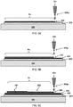
- FIG 1A and 1B illustrate manufacturing a skin-compatible electrode 100 by means of a printing, coating or dispensing process
- a preferred embodiment of manufacturing a skin-compatible electrode 100 comprises printing a conductive ink 300p onto a flexible substrate 200 which may be optionally attached to a temporary support 500.
- the conductive ink 300p may form an electrically conductive layer 300.
- the electrically conductive layer 300 is printed or dispensed according to a predefined circuit pattern P1.
- a conductive material printer 351 is used.
- the printer may comprise a print head, as shown.
- the circuit pattern P1 comprises an electrode pad area 301.
- the electrode pad area 301 may be used for transceiving electrical signals E via the skin S (not shown here).
- the circuit pattern P1 comprises a circuit lane 302.
- the circuit lane 302 can be electrically connected to the electrode pad area 301 for guiding the electrical signals E along the flexible substrate 200.
- another or further preferred embodiment comprises printing, coating or dispensing an adhesive composition 401p onto the printed electrode pad area 301 to form an adhesive interface layer 401.
- any other method and systems 352 suitable for coating or dispensing the materials and patterns as described herein may be used, in principle such as roll coating, gravure coating, reverse coating, roll brushing, spray coating, and air knife coating methods, immersing and curtain coating method, and extruding coating method with a die coater.
- the adhesive interface layer 401 is coated, dispensed or printed in an adhesive pattern P2.
- the adhesive interface layer 401 is conductive for, in use, maintaining an electrical connection for the electrical signals E between the electrode pad area 301 and the skin S (not shown here).
- the adhesive interface layer 401 is a dry film formed from the adhesive composition 401p.
- the adhesive composition 401p preferably comprises an ionically conductive pressure sensitive adhesive composition comprising a resin "R”, an ionic liquid “I”, and optionally electrically conductive particles "P".
- good conductive contact may be provided for transducing electrical signals E from the skin S to an external device.
- said conductive contact may be provided to allow prolonged use, e.g. wear, of formed electrodes 100 on - areas of skin.
- good conductive contact may advantageously be provided without skin irritation compared to conventional electrodes.
- the conductive adhesive interface layer 401 has relatively low skin-electrode impedance, e.g. at 10 Hz, below one hundred mega Ohm (M ⁇ ), preferably below fifty mega Ohm (M ⁇ ), more preferably below ten mega Ohm (M ⁇ ), most preferably below one mega Ohm (M ⁇ ), for example in a range between 500 and 100 kilo Ohm (k ⁇ ).
- skin-electrode impedance e.g. at 10 Hz, below one hundred mega Ohm (M ⁇ ), preferably below fifty mega Ohm (M ⁇ ), more preferably below ten mega Ohm (M ⁇ ), most preferably below one mega Ohm (M ⁇ ), for example in a range between 500 and 100 kilo Ohm (k ⁇ ).
- an electrically conductive adhesive layer is provided to obtain good transduction of electrical signals from skin to patch. In other or further preferred embodiments, such transduction is possible without the need of additional water-based fluids such as sweat.
- the electrode pad area 301 is compliant, e.g. having a combined stiffness less than two hundred thousand Newton per meter (200 000 N/m) more preferably below ten thousand Newton per meter (10 000 N/m).
- the stiffness is obtained by measuring the sample clamped in a tensile tester (Mark 10 ESM303) over the long side. The sample is elongated to 1% strain, preferably to 10% strain.
- the materials have preferably a Young's modulus "M” below two hundred mega Pascal, preferably less than one hundred mega Pascal (e.g. in plane of the flexible substrate 200) and thickness less than half a millimeter, preferably less than hundred micrometer.
- a combined thickness "T" of the flexible substrate 200, the electrically conductive layer 300 at the electrode pad area 301, and the adhesive interface layer 401, and their respective material compositions are adapted to provide the said stretchability.
- the flexible substrate 200 is disposed on, e.g. attached to, a (temporary) carrier substrate 500, as shown.
- the carrier substrate 500 may provide structural stability to the flexible substrate 200 during the manufacturing process.
- the carrier substrate 500 is relatively stiff, e.g. has a higher Young's modulus and thickness than the flexible substrate, e.g. higher by a factor ten or more.
- an arrow marked "M” indicates the preferred stretchability of the skin-compatible electrode 100.
- a layer thickness and material of the flexible substrate, the conductive pattern, and the conductive adhesive interface are adapted to provide a combined Young's modulus "M" below 100 MPa at the electrode pad area in plane of the flexible substrate 200.
- Such substrate consists preferably out of an elastomeric based (elastic) film.
- the flexible substrate 200 is a medical grade polyurethane film. Such films provide good breathability and permeation to humidity.
- suitable materials may be TPU films such as those available from Delstar Technologies, Lubrizol, BASF, and Covestro.
- the film thickness of the flexible substrate 200 is preferably in the range between 25 and 200 ⁇ m, preferably in a range between 50 and 150 ⁇ m, e.g. 75 ⁇ m.
- the flexible substrate 200 is preferably stretchable, e.g. having a Young's modulus below 100 MPa.
- other types of films e.g. rubbery films, may be used.
- silicone-based films may be used as substrates due to their excellent mechanical properties.
- Substrates based on polyether block amides, PET, PP, PEN, PEBAX and VESTAMIDE may be used as well.
- the conductive ink 300p ink may be an ink or paste and typically comprises electrically conductive particles and a resin.
- electrically conductive particles are selected from the group consisting of metal particles and metal nanoparticles, metal containing particles and nanoparticles, graphite particles and nanoparticles, carbon particles and nanoparticles, carbon nanowires, conductive polymer particles and nanoparticles, and mixtures thereof, more preferably selected from the group consisting of silver containing particles, silver particles, copper particles, copper containing particles, silver nanowires, copper nanowires, graphite particles, carbon particles and mixtures thereof, and even more preferably selected from graphite particles, carbon particles and mixtures thereof.
- the ink may comprise conductive polymers, such as PEDOT:PSS (Poly(3,4-ethylenedioxythiophene)) or PANI (Polyaniline).
- conductive polymers such as PEDOT:PSS (Poly(3,4-ethylenedioxythiophene)) or PANI (Polyaniline).
- ionic conductors such as Ag/AgCl or doped semiconducting materials such as Al doped ZnO, ITO or TiN particles may be used to provide conductivity.
- the conductive ink 300p preferably has a viscosity in the range between 0,001 and 100 Pa ⁇ s.
- the thickness of formed electrode pad area 301 is preferably in a range between 1 and 50 ⁇ m, more preferably between 2 and 20 ⁇ m, e.g. 10 ⁇ m.
- Providing an electrode pad area 301 with a thickness below the preferred range may lead to a film with defects and/or reduced conductivity.
- Providing an electrode pad area 301 with a thickness above the preferred range may lead to an unacceptable increase in material cost and/or to an unacceptably high stiffness of formed conductive layer.
- By providing a stiffness below 200 000 N/m and preferably 10 000 N/m at the electrode pad area the formed skin-compatible electrode in use may be adapted to adhere to, and/or flex, and/or stretch along with the area of skin it is adhered to.
- By providing a flexible skin-compatible electrode adhesive failure between the electrode and skin may be avoided and/or comfort for the user during wear of the skin-compatible electrode may improved.
- Printing may be a particularly suitable technique to provide layers with a thickness in the specified ranges. Printing may be particularly suitable in depositing films in a pre-defined pattern, e.g. intricate patterns, in combination with the specified thickness ranges.
- conformal adhesion of the skin-compatible electrode 100 to the skin is provided at least for the area of the skin that is covered by the electrode pad area 401 during normal wear of the skin-compatible electrode 100 without peeling off or translocation of the electrode along the skin during wearing to avoid motion artifacts disturbing the measurement.
- an electrically insulating skin adhesive is applied on the electrode 100 around the electrode pad 401 and leaving an area open for connecting the tab or snap at the end of the lead 302.
- the skin-compatible electrode 100 is also removable from the skin S when desired without damaging the skin S.
- the skin-compatible electrode 100 is suitable for application on the skin at many locations of the body: e.g.
- the skin-compatible electrode 100 is also suitable for application on skin of the head, for example, for use in electroencephalography measurements (EEG).
- the skin-compatible electrode 100 is also suitable for application on skin of the pregnant belly, for example, for use in electrohysterography measurements (EHG).
- the skin-compatible electrode 100 is also suitable for application on skin over a specific muscle, for example, for use in electromyography measurements (EMG).
- EMG electromyography measurements
- the electrode is also suitable for skin more prone to deformations and or flexing during wear such as locations on limbs.
- good adhesion over extended periods of time is obtained enabling continuous electrical contact between skin and electrode pads to enable signal recording over prolonged periods of time: i.e. >7 days; > 30 days; without signal degradation.
- conductive inks allowing stretching up to at least 1% or even at least 10% before losing essential electrical conductivity is preferred.
- Such inks include products such as LOCTITE ECI 1501 E&C and LOCTITE ECI 1010 E&C from Henkel.
- improved stretchability e.g. up to 5% or even 10%, may be provided in combination with circuit pattern P1 design, e.g. a pattern suited to provide wavy or meandering circuit lanes 302.
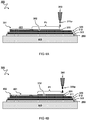
- FIG 2A illustrates a cross-section view of printing a skin insulating pattern P3.
- the method preferably comprises printing an electrically insulating ink composition 311p in a skin electrically insulating pattern P3 to form a skin insulating layer 311.
- an insulating material printer 353 is used, as shown.
- the skin insulating layer 311 covers at least part of the circuit lane 302 adjacent the electrode pad area 301.
- the circuit lane 302 may advantageously be electrically insulated from the skin S. Hence, unwanted interference of electrical signals resulting from contact between the skin S and the circuit lane 302 may be avoided.
- FIG 2B illustrates a cross-section view of printing a dielectric skin adhesive pattern P4.
- a skin adhesive composition printer 354 is used, as shown.
- the method comprises printing an electrically insulating skin adhesive composition 402p in a pattern P4 to form a dielectric skin adhesive layer 402.
- the electrically insulating skin adhesive layer 402 may be provided on the flexible substrate 200 and/or on the circuit lane 302.
- the electrically insulating skin adhesive layer 402 is provided at areas adjacent to the adhesive pattern P2.
- the provided electrically insulating skin adhesive layer 402 may, in use, improve the adhesion of the electrode 100 on the skin S.
- FIG 3A illustrates a cross-section view of printing an exterior shielding pattern P5.
- the method comprises printing a conductive ink 300p in an exterior shielding pattern P5 to form an exterior shielding layer 322.
- the same or similar conductive material printer 351 as in FIG 1A can be used, as shown.
- the exterior shielding layer 322 is printed on the flexible substrate 200 before printing the electrically conductive layer 300.
- the electrically conductive layer 300 in use, may be shielded from exterior electromagnetic interference. This shielding may be provided in passive or in active mode.
- FIG 3B illustrates a cross-section view of printing an intermediary insulating pattern P6.
- the same or similar electrically insulating material printer 353 as in FIG 2A can be used, as shown.
- the method comprises printing an electrically insulating composition 311p in an intermediary electrically insulating pattern P6 to form an exterior insulating layer 312 on the exterior shielding layer 322 before printing the electrically conductive layer 300.
- the exterior shielding layer 322 may be electrically insulated from the electrically conductive layer 300.
- FIG 3C illustrates printing the circuit pattern P1 similar as FIG 1A , but now printed onto the intermediary insulating pattern P6 and shielding pattern P5.
- an electrode 100 may be obtained with the properties as in FIG 1A but with the added benefit of having a shielding layer to, in use, reduce unwanted interference.
- FIG 4A illustrates a cross-section view of printing the skin insulating pattern P3 similar as FIG 2A but on top of a stack including an exterior shielding layer 322.
- FIG 4B illustrates a cross-section view of printing a skin shielding pattern P7.
- the same or similar conductive material printer 351 as in FIG 1A can be used, as shown.
- the method comprises printing the conductive ink 300p in a skin shielding pattern P7 to form a skin shielding layer 321.
- the skin shielding layer 321 does not contact the electrode 300.
- Contacting the adhesive interface layer 401 may lead to the exterior shielding layer 322 functioning as an antenna, thereby introducing unwanted electromagnetic interference.
- the skin shielding layer 321 may, in use, shield the electrically conductive layer 300 from electromagnetic interference.
- the skin insulating layer 311 is arranged between the skin shielding layer 321 and the circuit lane 302 for electrically insulating the skin shielding layer 321 from the electrically conductive layer 300. More preferably, the skin shielding layer 321 is electrically connected to the exterior shielding layer 322. By connecting the shielding layers, preferably along a length of the circuit lane 302 a coaxial shielding effect may be attained.
- the present disclosure relates to a skin-compatible electrode 100, manufactured according to any of the manufacturing methods described herein.
- the electrode 100 comprises one or more aspects as described herein. It will be appreciated that by providing the electrode 100 with one or more of the elements described herein will be accompanied with the same or similar benefits as described for the corresponding elements in relation with the manufacturing methods.
- the electrode 100 preferably comprises a flexible and/or stretchable substrate 200. More preferably, the electrode 100 comprises an electrically conductive layer 300 forming a circuit pattern P1 disposed onto the exterior insulating layer 312.
- the circuit pattern P1 comprises an electrode pad area 301 and a circuit lane 302, as described.
- the electrode 100 comprises an adhesive interface layer 401 formed by a dry film of an adhesive composition 401p with an ionically conductive pressure sensitive adhesive composition comprising a resin "R", an ionic liquid “I”, and optionally electrically conductive particles "P".
- the electrode 100 comprises an exterior shielding layer 322.
- the electrode 100 comprises an exterior insulating layer 312.
- the electrode 100 comprises a skin insulating layer 311.
- the electrode 100 comprises a skin shielding layer 321.
- the skin insulating layer 311 is arranged between the skin shielding layer 321 and the circuit lane 302.
- the electrode 100 comprises a dielectric skin adhesive layer 402.
- the same ink 300p is used for printing the respective electrically conductive layer 300 and shielding layers 321, 322.
- different inks or other electrically conducting materials may be used.
- the same dielectric composition 311p is used to form the respective insulating layers 311, 312.
- different dielectric materials may be used.
- the adhesive composition 401p is printed as solution comprising a solvent, and the adhesive interface layer 401 is a dry film formed after evaporation of the solvent.
- the amount of solvent in the solution and/or the type of solvent in the solution may be adjusted.
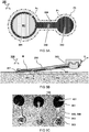
- FIG 5A illustrates a plane view of a skin-compatible electrode 100 according to a substrate cut pattern P8.
- the flexible substrate 200 is cut according to a substrate cut pattern P8.
- the circuit pattern P1 forms a subset area of the substrate cut pattern P8.
- the conductive ink 300p is preferably printed exclusively on parts of the flexible substrate 200 which will form the electrode 100. For example, this may save expensive printing material, e.g. conductive ink comprising silver particles.
- the adhesive pattern P2 forms a subset area of the circuit pattern P1.
- an intersection of the adhesive interface layer 401 and the electrically conductive layer 300 may define the effective extent of the electrode pad area 301.
- the adhesive interface layer overlaps, e.g., coincides with the electrode pad area 300.
- the electrode pad area 301 has a dimension in a range between 5 and 75 mm, more preferably in a range between 7.5 and 50 mm, most preferably in a range between 10 and 30 mm.
- the thickness of formed adhesive interface layer 401 is preferably in a range between 5 and 50 ⁇ m, more preferably between 10 and 40 ⁇ m, e.g. 20 ⁇ m. Providing a conductive layer with a thickness below the preferred range may in use lead to poor adhesive properties, e.g. detaching from the skin and/or shifting (moving) of the skin-compatible electrode 100 with respect to the skin.
- the electrode pad area 301 has an area between 20 to 4500 millimeter (mm 2 ), preferably between 45 to 2000 square millimeter (mm 2 ), more preferably between 60 to 1500 (mm 2 ), and most preferably between 75 to 700 square millimeter (mm 2 ).
- One benefit of providing a skin-compatible electrode 100 with a large electrode pad area 301 may be an increased signal to noise ratio.
- An upper limit for the electrode pad area 301 relates to the limited availability of skin area, especially in applications requiring the application of multiple skin-compatible electrodes 100, or in applications wherein the body part or person is small, for example for children.
- FIG 5B illustrates a cross-section view of the electrode 100 as used on the skin "S".
- the electrically conductive layer 300 comprises an external connection area 303.
- the external connection area 303 may be a reinforced region of the circuit lane 302.
- the external connection area 303 may be connected to an ExG (Electrocardiography, Electroencephalography, Electromyography, Electrohysterography) device using a rivet (as shown), electrical clamp, or any other electrical connecting means.
- ExG Electrocardiography, Electroencephalography, Electromyography, Electrohysterography
- FIG 5C shows a photograph of an example of electrodes 100 manufactured as described herein.
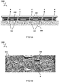
- FIG 6A illustrates a cross-section view of an electrode patch 1000 as used on the skin "S".
- the method comprises manufacturing a plurality of electrodes 100 on a common flexible substrate 200. More preferably, the electrodes 100 are arranged according to a pre-defined electrode pattern for transceiving a plurality of electrical signals "E" at respective areas of the skin "S". Most preferably, the electrode pattern comprises at least 3, e.g. 3 to 7, or 3 to 5, e.g. three electrodes 100 for measuring ECG signals via the skin "S".
- the electrode pad areas 301 of the electrodes 100 are covered by respective adhesive interface layers 401.
- the areas of the skin-compatible patch 1000 between the electrode pad areas 301 are covered by an electrically insulating skin adhesive layer 402.
- Providing an electrically insulating skin adhesive layer 402 may, in use, improve adhesion between skin "S" and the electrode patch 1000.
- FIG 6B shows a photograph of an example of a skin-compatible patch 1000 manufactured as described herein.
- the respective circuit lanes 302 of the electrodes converge at a common external connection area 303. This may allow making the connection to an external device in a fast and convenient way. It may further reduce the risk of user error in connecting the patch to the external device, especially in combination with a cable with matching connector such as a crimp connector (e.g. Nicomatic Crimpflex).
- a crimp connector e.g. Nicomatic Crimpflex
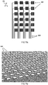
- FIG 7A illustrates a plane view of a grid shaped circuit pattern P1.
- the grid shaped circuit pattern P1 forms a two-dimensional array of spaced apart electrode pad areas 301 with respective circuit lanes 302.
- the patch comprises an array of electrode pad areas covered by dry conductive adhesive interface 401 layers for in use measuring spatial variation of electrical signals "E" over an area of the skin "S".
- these or other patterns may be advantageous for measuring EMG signals, or the like.
- FIG 7B shows a photo of a grid of electrodes 100.
- the grid may be used in a measurement system.
- the various aspects as described herein may be embodied as an ExG system, e.g. Electrocardiography, Electroencephalography, Electromyography, Electrohysterography, et cetera.
- the system comprises at least one electrode 100 and/or patch electrode patch 1000 as described herein, e.g. obtained or obtainable by any of the described methods.
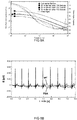
- FIG 8A depicts impedance spectra comparing exemplary embodiments of skin-compatible electrodes 100 with differing dimensions comprising a pressure adhesive layer and comparative a gel-type electrode.
- a photo of the electrode pads of exemplary embodiments of electrodes is shown in FIG 5C .
- the depicted impedance spectra illustrate that the exemplary embodiments and comparative electrode show similar performance.
- the depicted impedance spectra further illustrate that the resistance or impedance of electrodes, as described above, may be influenced by changing the area of the electrode pad.
- FIG 8B depicts exemplary time traces of electrical signals "E" from skin "S", recorded using a comparative gel-type electrode and a skin-compatible electrode 100 obtained according to the disclosed method. Shown traces have been obtained after 8 hours of continuous wear of said electrodes. The depicted time traces further illustrate that the exemplary embodiment of the skin-compatible electrode 100 has a performance similar to the comparative gel-type electrode.
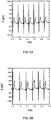
- FIG 9 depicts exemplary time traces of electrical signals "E” from skin "S", recorded over a total time frame of 5 days. Said traces have been obtained during continuous wear of an exemplary embodiment of a skin-compatible electrode 100 comprising a pressure sensitive adhesive. Time traces have been obtained with 1-day intervals.
- FIG 9A depicts a time trace recorded on day 1
- FIG 9B depicts a time trace recorded on day 5. The depicted time traces further illustrate that exemplary embodiments described herein above may be worn and used on an area of skin for prolonged periods of time without visible changes in recorded signal quality.
- the adhesive composition 401p e.g. pressure sensitive adhesive composition (pressure sensitive adhesive) are described in more detail.
- pressure sensitive adhesive composition pressure sensitive adhesive
- Each aspect so described may be combined with any other aspect or aspects unless clearly indicated to the contrary.
- any feature indicated as being preferred or advantageous may be combined with any other feature or features indicated as being preferred or advantageous.
- the dry electrode adhesive according to the present invention is an ionically conductive pressure sensitive adhesive (PSA) with low impedance and good skin compatibility.
- PSA pressure sensitive adhesive
- the ionically conductive pressure sensitive adhesive according to the present invention is preferably based on a silicone or acrylate resin, most preferably a polar solvent-based acrylic pressure sensitive adhesive with high breathability and a non-toxic, non-irritating ionic liquid leading to ionic conductivity.
- the ionically conductive pressure sensitive adhesive composition 401p according to the present invention can be used as a dry film, which offers a solution for long-term monitoring of biosignals by acting as a functional contact between electrode and skin. In contrast to gel-type electrodes currently in the market it cannot dry out and it does not lead to skin irritation. Furthermore, the impedance of the PSA according to the present invention is very low without any addition of water.
- the ionically conductive pressure sensitive adhesive composition comprises a (meth)acrylate resin comprising (meth)acrylate monomer comprising OH-group (hydroxyl group) and an ionic liquid.
- the ionically conductive pressure sensitive adhesive composition 401p comprises a (meth)acrylate resin comprising at least 10% of a (meth)acrylate monomer comprising OH-group by weight of the total weight of the (meth)acrylate resin.
- Suitable (meth)acrylate resin for use in the present invention is preferably formed from the monomers selected from the group consisting of hydroxyethyl acrylate, hydroxypropyl acrylate, hydroxybutyl acrylate, methyl methacrylate, butyl acrylate, ethylhexyl acrylate, acrylic acid, C1-C18 alkyl (meth)acrylate, (meth)acrylamide, vinyl acetate, N-vinyl caprolactame, acrylonitrile, vinyl ether, benzyl (meth)acrylate, cyclohexyl (meth)acrylate, glycidyl (meth)acrylate and mixtures thereof, preferably formed from the monomers selected from the group consisting of hydroxyethyl acrylate, methyl methacrylate, butyl acrylate, ethylhexyl acrylate and mixtures thereof, and more preferably said (meth)acrylate resin is formed from hydroxyethyl
- Suitable commercially available (meth)acrylate resins for use in the present invention include, but not limited to Loctite DURO-TAK 222A, Loctite DURO-TAK 87-202A; Loctite DURO-TAK 87-402A; Loctite DURO-TAK 73-626A from Henkel.
- a PSA comprising a (meth)acrylate resin, especially comprising at least 10% of a (meth)acrylate monomer comprising OH-group provides good impedance and electrodes do not dry out and they can be used for longer period measurement (the higher OH content increases the water vapor transmission rate of the polymer, which contributes to increased breathability and longer wear times).
- Preferably content of said (meth)acrylate monomer comprising OH-group in said (meth)acrylate resin is at least 15% by weight of the total weight of the (meth)acrylate resin, preferably at least 20%, more preferably at least 25%, and most preferably at least 30%, but no more than 65%, preferably no more than 60%, more preferably no more than 55%, and most preferably no more than 50%.
- the (meth)acrylate monomer comprising OH-group in said (meth)acrylate resin is more than 65% by weight of the total weight of the (meth)acrylate resin, the higher OH-group content may negatively effect the adhesion properties.
- An ionically conductive pressure sensitive adhesive composition 401p according to the present invention may comprise said (meth)acrylate resin from 5 to 80% by weight of the total weight of the composition, preferably from 15 to 75% and more preferably from 30 to 70%.
- An ionically conductive pressure sensitive adhesive composition 401p according to the present invention comprises an ionic liquid, preferably a non-toxic, non-irritating ionic liquid leading to ionic conductivity.
- an ionically conductive pressure sensitive adhesive composition 401p comprises an ionic liquid selected from the group consisting of imidazolium acetates, imidazolium sulfonates, imidazolium chlorides, imidazolium sulfates, imidazolium phosphates, imidazolium thiocyanates, imidazolium dicyanamides, imidazolium benzoates, imidazolium triflates, choline triflates, choline saccharinate, choline sulfamates, pyridinium acetates, pyridinium sulfonates, pyridinium chlorides, pyridinium sulfates, pyridinium phosphates, pyridinium thiocyanates, pyridinium dicyanamides, pyridinium benzoates, pyridinium triflates, pyrrolidinium acetates, pyr
- ionic liquid refers to a specific class of molten salts which are liquids at temperatures of 100° C or below.
- said ionic liquid “I” is selected from the group consisting of 1-ethyl-3-methylimidazolium (EMIM) acetate, 1-ethyl-3-methylimidazolium methanesulfonate, 1-ethyl-3-methylimidazolium trifluoromethanesulfonate, 1-ethyl-3-methylimidazolium chloride, 1-ethyl-3-methylimidazolium ethylsulfate, 1-ethyl-3-methylimidazolium diethylphosphate, 1-ethyl-3-methylimidazolium thiocyanate, 1-ethyl-3-methylimidazolium dicyanamide, 1-ethyl-3-methylimidazolium benzoate, choline trifluormethanesulfonate, choline saccharinate, choline acesulfamate, choline N -cyclohexylsulfamate, tris(2-amino
- the ionic liquid "I" is selected from the group consisting of 1-ethyl-3-methylimidazolium benzoate, 1-ethyl-3-methylimidazolium tetrafluoroborate, 1-ethyl-3-methylimidazolium methanesulfonate, 1-ethyl-3-methylimidazolium chloride, 1-ethyl-3-methylimidazolium trifluoromethanesulfonate, choline trifluoromethanesulfonate, 1-ethyl-3-methylimidazolium acetate, choline acetate, 1-ethyl-3-methylimidazolium diethylphosphate, 1-ethyl-3-methylimidazolium bis(trifluoromethylsulfonyl)imide, 1-ethyl-3-methylimidazolium ethyl sulfate, 1-ethyl-3-methylimidazolium thiocyanate, 1-
- ionic liquids are preferred because they have good solubility in the resin, in particular (meth)acrylate resin, according to the present invention and low toxicity.
- Suitable commercially available ionic liquids for use in the present invention include, but not limited to Basionics ST80, Basionics Kat1, Basionics BC01, Basionics VS11, Basionics VS03, and Efka IO 6785, all from BASF.
- An ionically conductive pressure sensitive adhesive composition 401p according to the present invention may comprise an ionic liquid from 0.1 to 35% by weight of the total weight of the composition, preferably from 0.5 to 25%, and more preferably from 1 to 15%.
- the adhesive may not show any ionic conductivity and the signal may be lost, whereas too high quantity may not provide improvement in signal quality but may increase the chances of skin irritation and decrease the adhesion properties.
- An ionically conductive pressure sensitive adhesive composition 401p according to the present invention may further comprise an ionic conductivity promoter, preferably a non-toxic, non-irritating ionic conductivity promoter leading to additional ionic conductivity.
- the ionic conductivity promoter is semi-solid or solid under room temperature and can be dissolved in the ionic liquid. It has good compatibility with the (meth)acrylate resin according to the present invention.
- the ionic conductivity promoter suitable for the present invention is selected from choline chloride, choline bitartrate, choline dihydrogen citrate, choline phosphate, choline gluconate, choline fumarate, choline carbonate, choline pyrophosphate and mixture thereof.
- the ionically conductive pressure sensitive adhesive composition 401p according to the present invention may comprise an ionic conductivity promoter from 0.1 to 35% by weight of the total weight of the composition, preferably from 0.5 to 25%, and more preferably from 1 to 15%.
- the pressure sensitive adhesive may not show any ionic conductivity and the signal may be lost, whereas too high quantity may not provide improvement in signal quality but may increase the chances of skin irritation and decrease the adhesion properties.
- the ionically conductive pressure sensitive adhesive composition 401p according to the present invention may further comprise electrically conductive particles.
- electrically conductive particles are selected from the group consisting of metal particles and metal nanoparticles, metal containing particles and nanoparticles, graphite particles and nanoparticles, carbon particles and nanoparticles, carbon nanowires, conductive polymer particles and nanoparticles, and mixtures thereof, more preferably selected from the group consisting of silver containing particles, silver particles, copper particles, copper containing particles, silver nanowires, copper nanowires, graphite particles, carbon particles and mixtures thereof, and even more preferably selected from graphite particles, carbon particles and mixtures thereof.
- Graphite particles and carbon particles are preferred due the fact that they do not cause skin irritation but provide adequate conductivity.
- Suitable commercially available electrically conductive particles for use in the present invention include, but not limited to Ensaco 250G, Timrex KS6 from Timcal, Printex XE2B from Necarbo, C-Nergy Super C65 from Imerys and Vulcan XC72R from Cabot.
- An ionically conductive pressure sensitive adhesive composition 401p according to the present invention may comprise said electrically conductive particles from 0.1 to 35% by weight of the total weight of the composition, preferably from 0.5 to 25%, and more preferably from 1 to 15%.
- the quantity of the electrically conductive particles is too low, it may lead to poor conductivity, whereas too high quantity may lead to loss of adhesion properties.
- An ionically conductive pressure sensitive adhesive composition 401p according to the present invention may further comprise a polyether polyol.
- the polyether polyol is selected from polyethylene glycol (PEG), polypropylene glycol (PPG), polytetramethylene glycol (PTMG) and mixtures thereof.
- PEG polyethylene glycol
- PPG polypropylene glycol
- PTMG polytetramethylene glycol
- the polyether polyol may have a weight averaged molecular weight (Mw) from 300 to 1000 g/mol, preferably from 350 to 750 g/mol and more preferably from 380 to 420 g/mol, wherein the molecular weight is measured by gel permeation chromatography according to DIN 55672-1:2007-08 with THF as the eluent.
- Mw weight averaged molecular weight
- Suitable commercially available polyether polyols for use in the present invention include, but are not limited to Kollisolv PEG 401 from BASF.
- An ionically conductive pressure sensitive adhesive composition 401p according to the present invention may comprise polyether polyol from 0.1 to 35% by weight of the total weight of the composition, preferably from 0.5 to 25% and more preferably from 1 to 15%.
- Too high polyether polyol quantity may lead to loss of adhesion properties.
- An ionically conductive pressure sensitive adhesive composition 401p according to the present invention may further comprise a solvent.
- Suitable solvent for use in the present invention may be selected from the group consisting of water, ethyl acetate, butyl acetate, butyl diglycol, 2-butoxyethanol, ethylene glycol, diethylene glycol, propylene glycol, dipropylene glycol, methanol, isopropanol, butanol, dibasic esters, hexane, heptane, 2,4-pentadione, toluene, xylene, benzene, hexane, heptane, methyl ethyl ketone, methyl isobutyl ketone, diethylether and mixtures thereof, preferably said solvent is selected from the group consisting of ethyl acetate, butyl acetate, ethylene glycol, propylene glycol and mixtures thereof.
- Suitable commercially available solvents for use in the present invention include, but not limited to ethyl acetate and ethylene glycol from Brenntag, butyl acetate from Shell Chemicals and propylene glycol from Lyondell.
- An ionically conductive pressure sensitive adhesive composition 401p according to the present invention may comprise a solvent from 10 to 90% by weight of the total weight of the composition, preferably from 20 to 80%, and more preferably from 30 to 70%.
- An ionically conductive pressure sensitive adhesive composition 401p according to the present invention has an impedance value below 100,000 Ohm at 1 kHz, preferably, below 20,000 Ohm at 1 kHz, wherein said impedance is measured by connecting two electrodes coated each with 25 ⁇ m of an ionic conductive pressure sensitive adhesive having a contact area of 0.25 cm 2 .
- the combination of the (meth)acrylate resin and the ionic liquid leads to a low impedance.
- the ionic liquid provides the ionic conductivity, however, if the ionic liquid "I" is not miscible with the (meth)acrylate resin, one will not see any ionic conductivity in the pressure sensitive adhesive.
- the additional OH-groups from the PEG make the system more polar and enhance the ionic conductivity of the ionic liquid "I" in the (meth)acrylate resin.
- An ionically conductive pressure sensitive adhesive composition 401p according to the present invention has high breathability. Good breathability is obtained if the water can penetrate easily through the adhesive layer. To achieve this effect, a quite polar resin is required, in this occasion, the OH-functionalities support and improve the breathability.
- Adhesive according to the present invention has a breathability value of about 4200 g/m 2 in 24 hours.
- a standard acrylic PSA has a breathability value of about 2000 g/m 2 in 24 hours.
- the breathability is measured through a moisture vapor transmission rate (MVTR) measurement according to ASTM D1653.
- the present invention also relates to a dry film formed from the ionically conductive pressure sensitive adhesive composition 401p according to the present invention.
- the dry film formation can be done by coating the ionically conductive pressure sensitive adhesive composition on a supporting substrate (such as a film) and drying the film in an oven at for example 120°C for 3 minutes to remove the solvent and form a dry film of the ionically conductive pressure sensitive adhesive on the supporting substrate.
- a supporting substrate such as a film
- the known method used for preparing pressure-sensitive adhesive can be used. Specifically, examples include roll coating, gravure coating, reverse coating, roll brushing, spray coating, and air knife coating methods, immersing and curtain coating method, and extruding coating method with a die coater.
- the present invention also relates to use of an ionically conductive pressure sensitive adhesive composition 401p according to the present invention in skin applications as a contact medium as part of electrodes measuring biosignals from the skin.
- the present invention also encompasses use of a dry film according to the present invention in skin applications as a contact medium as part of electrodes measuring biosignals from the skin.
Landscapes
- Life Sciences & Earth Sciences (AREA)
- Health & Medical Sciences (AREA)
- Medical Informatics (AREA)
- Animal Behavior & Ethology (AREA)
- Pathology (AREA)
- Engineering & Computer Science (AREA)
- Biomedical Technology (AREA)
- Heart & Thoracic Surgery (AREA)
- Physics & Mathematics (AREA)
- Molecular Biology (AREA)
- Surgery (AREA)
- Biophysics (AREA)
- General Health & Medical Sciences (AREA)
- Public Health (AREA)
- Veterinary Medicine (AREA)
- Measurement And Recording Of Electrical Phenomena And Electrical Characteristics Of The Living Body (AREA)
- Electrotherapy Devices (AREA)
- Chemical & Material Sciences (AREA)
- Dispersion Chemistry (AREA)
Abstract
A method of manufacturing a skin-compatible electrode (100) comprises printing a circuit pattern (P1) onto a flexible substrate (200) to form an electrically conductive pattern including an electrode pad area (301). A layer of an adhesive composition (401p) is printed in a second pattern (P2) onto the electrode pad area (301) to form an adhesive interface layer (401). The adhesive interface layer (401) is a dry film formed from the adhesive composition (401p) comprising an ionically conductive pressure sensitive adhesive composition comprising a resin (R), an ionic liquid (I), and optionally electrically conductive particles (P). A layer thickness and material of the flexible substrate, the conductive pattern, and the conductive adhesive interface have relatively low stiffness in plane of the flexible substrate (200).

Description
- The present invention relates to a method for the production of ExG electrodes and patches for application to human subjects.
- Bio potential electrodes are used to measure bio signals such as electrocardiography (ECG), electroencephalography (EEG) and electromyography (EMG).
- For example, currently used ECG electrodes are connected to the skin via gel, which acts as an electrolyte and couples the electrical potential in the body to the electrode. However, presently used electrodes typically dry out over time and cannot be used for prolonged measurements. Most of the presently used electrodes are not recommended for use longer than 24h. In addition, they do not have long storage times in air. Most of the presently used electrodes expire within one month after opening the hermetic packaging preventing them from drying out during storage.
- Currently used gel electrodes comprise high salt concentrations, which are needed for providing low impedances and good signal quality, however at the same time they cause skin irritation with many patients. Furthermore, presently used electrodes which are based on a hydrogel contain relatively high quantities of water. The high water content is the reason why these electrodes tend to dry out over time. Presently used electrodes which are based on ionic conductivity can therefore not be used for long-term measurements (e.g. three days) since the signal quality decreases along with decreasing water content. Current gel electrodes are attached to the skin with a ring of a pressure sensitive skin adhesive surrounding the inner gel.
- There are also tab electrodes currently on the market, which are attached to the skin via a gel-type adhesive. These electrodes do not need an additional skin adhesive, since the gel itself is adhering to the skin. However, these electrodes also comprise a salt and water, and dry out over time and are therefore not suitable for prolonged measurements. The cohesion of the adhesive is often poor in these electrodes, which for example leads to cohesive failure upon removal of the electrode. Furthermore, production of such electrodes is laborious due to the difficult handling of the adhesive, e.g. placement of the gel film atop the conductive bottom layers.
- Alternatively, a pressure sensitive adhesive comprising conductive fillers, such as carbon black can be used in the electrodes to measure bio signals. The drawback in this kind of electrodes is that a high carbon black concentration is needed, which leads to reduced adhesion properties. Furthermore, the signal quality in this kind of electrodes is poor.
- In another electrode solution, the electrode comprises adhesives comprising the combination of carbon black and a salt. An electrophoretic alignment of conductive fillers is required in order to obtain sufficient impedances in this solution. However, this electrophoretic activation step makes the electrode production expensive and complicated.
- Therefore, there is a need for electrodes and a method for the production of such electrodes to measure bio signals, which mitigate one or more of the above problems.
- Aspects of the present disclosure relate to a method of manufacturing a skin-compatible electrode. Preferably, the method comprises printing a conductive ink onto a flexible substrate to form an electrically conductive layer in a circuit pattern comprising an electrode pad area and a circuit lane. The method further comprises coating, printing or dispensing an adhesive composition onto the printed electrode pad area to form an adhesive interface layer in an adhesive pattern. The adhesive interface layer may be a dry film formed from the adhesive composition comprising an ionically conductive pressure sensitive adhesive composition comprising a resin, an ionic liquid, and optionally electrically conductive particles. Furthermore, a combined thickness and sizes of the flexible or stretchable substrate, the electrically conductive layer at the electrode pad area, and the adhesive interface layer, and their respective material compositions, are adapted to provide a low combined stiffness, at the electrode pad area in plane of the flexible substrate. The inventors find that electrodes having the combination of aforementioned structural, chemical, and mechanical properties may be especially suitable for long term use while allowing efficient manufacturing by printing, coating or dispensing.
- These and other features, aspects, and advantages of the apparatus, systems and methods of the present disclosure will become better understood from the following description, appended claims, and accompanying drawing wherein:
-
FIG 1A and 1B illustrate manufacturing a skin-compatible electrode by means of a printing, coating or dispensing process; -
FIG 2A illustrates a cross-section view of printing an electrically insulating pattern; -
FIG 2B illustrates a cross-section view of printing, coating or dispensing an electrically insulating skin adhesive pattern; -
FIG 3A illustrates a cross-section view of printing an exterior shielding pattern by printing a conductive layer; -
FIG 3B illustrates a cross-section view of printing an exterior shielding pattern by printing an electrically insulating layer on top of a conductive layer; -
FIG 3C illustrates a cross-section view of printing a shielding electrode by printing an electrically conductive layer on top of a shielding layer; -
FIG 4A illustrates a cross-section view of printing the skin insulating pattern similar asFIG 2A but on top of a stack including an exterior shielding layer; -
FIG 4B illustrates a cross-section view of printing a skin shielding pattern; -
FIG 5A illustrates a plane view of a skin-compatible electrode according to a substrate cut pattern; -
FIG 5B illustrates a cross-section view of the electrode as used on the skin; -
FIG 5C shows a photograph of an example of electrodes manufactured as described herein; -
FIG 6A illustrates a cross-section view of an electrode patch as used on the skin; -
FIG 6B shows a photograph of an example of a skin-compatible patch manufactured as described herein; -
FIG 7A illustrates a plane view of a grid shaped circuit pattern; -
FIG 7B shows a photo of a grid of electrodes; -
FIG 8A depicts impedance spectra comparing exemplary embodiments of skin-compatible electrodes 100 with differing dimensions comprising a pressure adhesive layer and comparative a gel-type electrode; -
FIG 8B depicts exemplary time traces of electrical signals "E" from skin "S", recorded using a comparative gel-type electrode and a skin-compatible electrode 100 obtained according to the disclosed method. Shown traces have been obtained after 8 hours of continuous wear of said electrodes. -
FIG 9A depicts exemplary time traces of electrical signals "E" from skin "S", recorded over a total time frame of 5 days recorded on day 1 with electrodes manufactured as described herein; -
FIG 9B depicts exemplary time traces of electrical signals "E" from skin "S", recorded over a total time frame of 5 days recorded on day 5 with electrodes manufactured as described herein; - Terminology used for describing particular embodiments is not intended to be limiting of the invention. As used herein, the singular forms "a", "an" and "the" are intended to include the plural forms as well, unless the context clearly indicates otherwise. The term "and/or" includes any and all combinations of one or more of the associated listed items. It will be understood that the terms "comprises" and/or "comprising" specify the presence of stated features but do not preclude the presence or addition of one or more other features. It will be further understood that when a particular step of a method is referred to as subsequent to another step, it can directly follow said other step or one or more intermediate steps may be carried out before carrying out the particular step, unless specified otherwise. Likewise, it will be understood that when a connection between structures or components is described, this connection may be established directly or through intermediate structures or components unless specified otherwise.
- As used herein below electrodes or single electrodes may be understood to be a single electrically conductive electrode to be placed onto skin. Typically, it is a disposable electrode comprising a lead, e.g. an external connection area, and a conductive adhesive layer on a thin film. Typically, electrodes are connectable to measurement equipment such as a Holter Monitor (e.g. Philips DigiTrak XT, GE CardioMem CM 3000) using a tab or snap connector. In the case of a tab e.g. an alligator clip can be used.
- A patch may be described to comprise a plurality of electrodes connected in a specific, e.g. pre-defined, geometry. In some embodiments, the patch may be described as an ECG patch where a number of electrodes (between 3 and 5) is located in such a configuration that an ECG can be measured.
- An electrode array may be understood to comprise a large number of electrodes placed in a, preferably regular, pattern. Typically, the number of electrodes in an array varies in a range between 20 to 100 electrodes.
- The invention is described more fully hereinafter with reference to the accompanying drawings, in which embodiments of the invention are shown. In the drawings, the absolute and relative sizes of systems, components, layers, and regions may be exaggerated for clarity. Embodiments may be described with reference to schematic and/or cross-section illustrations of possibly idealized embodiments and intermediate structures of the invention. In the description and drawings, like numbers refer to like elements throughout. Relative terms as well as derivatives thereof should be construed to refer to the orientation as then described or as shown in the drawing under discussion. These relative terms are for convenience of description and do not require that the system is constructed or operated in a particular orientation unless stated otherwise.
-
FIG 1A and 1B illustrate manufacturing a skin-compatible electrode 100 by means of a printing, coating or dispensing process; - As illustrated e.g. in
FIG 1A , a preferred embodiment of manufacturing a skin-compatible electrode 100 comprises printing aconductive ink 300p onto aflexible substrate 200 which may be optionally attached to atemporary support 500. For example, theconductive ink 300p may form an electricallyconductive layer 300. Preferably, the electricallyconductive layer 300 is printed or dispensed according to a predefined circuit pattern P1. In some embodiments, e.g. as shown, aconductive material printer 351 is used. For example, the printer may comprise a print head, as shown. Also, any other method and systems suitable for printing, dispensing the materials and patterns as described herein may be used, in principle such as screen printing, rotary screen printing, stencil printing, flexo printing, gravure printing, Laser-Induced Forward Transfer (LIFT) printing, ink jet printing, aerosol jet printing. In some embodiments, the circuit pattern P1 comprises anelectrode pad area 301. For example, theelectrode pad area 301 may be used for transceiving electrical signals E via the skin S (not shown here). In other or further embodiments, the circuit pattern P1 comprises acircuit lane 302. For example, thecircuit lane 302 can be electrically connected to theelectrode pad area 301 for guiding the electrical signals E along theflexible substrate 200. - As illustrated e.g. in
FIG 1B , another or further preferred embodiment comprises printing, coating or dispensing anadhesive composition 401p onto the printedelectrode pad area 301 to form anadhesive interface layer 401. Also any other method andsystems 352 suitable for coating or dispensing the materials and patterns as described herein may be used, in principle such as roll coating, gravure coating, reverse coating, roll brushing, spray coating, and air knife coating methods, immersing and curtain coating method, and extruding coating method with a die coater. Preferably, theadhesive interface layer 401 is coated, dispensed or printed in an adhesive pattern P2. As described herein, theadhesive interface layer 401 is conductive for, in use, maintaining an electrical connection for the electrical signals E between theelectrode pad area 301 and the skin S (not shown here). - In a preferred embodiment, the
adhesive interface layer 401 is a dry film formed from theadhesive composition 401p. As will be described and explained in further detail below, theadhesive composition 401p preferably comprises an ionically conductive pressure sensitive adhesive composition comprising a resin "R", an ionic liquid "I", and optionally electrically conductive particles "P". By using theadhesive composition 401p as specified herein good conductive contact may be provided for transducing electrical signals E from the skin S to an external device. By using theadhesive composition 401p as specified herein said conductive contact may be provided to allow prolonged use, e.g. wear, of formedelectrodes 100 on - areas of skin. By using theadhesive composition 401p as specified herein good conductive contact may advantageously be provided without skin irritation compared to conventional electrodes. - In preferred embodiments, the conductive
adhesive interface layer 401 has relatively low skin-electrode impedance, e.g. at 10 Hz, below one hundred mega Ohm (MΩ), preferably below fifty mega Ohm (MΩ), more preferably below ten mega Ohm (MΩ), most preferably below one mega Ohm (MΩ), for example in a range between 500 and 100 kilo Ohm (kΩ). Typically, signals with better signal to noise ratio are possible with increasingly lower impedance. In some preferred embodiments an electrically conductive adhesive layer is provided to obtain good transduction of electrical signals from skin to patch. In other or further preferred embodiments, such transduction is possible without the need of additional water-based fluids such as sweat. - Preferably, the
electrode pad area 301 is compliant, e.g. having a combined stiffness less than two hundred thousand Newton per meter (200 000 N/m) more preferably below ten thousand Newton per meter (10 000 N/m). Where the stiffness is obtained by measuring the sample clamped in a tensile tester (Mark 10 ESM303) over the long side. The sample is elongated to 1% strain, preferably to 10% strain. - For example, the materials have preferably a Young's modulus "M" below two hundred mega Pascal, preferably less than one hundred mega Pascal (e.g. in plane of the flexible substrate 200) and thickness less than half a millimeter, preferably less than hundred micrometer. For example, a combined thickness "T" of the
flexible substrate 200, the electricallyconductive layer 300 at theelectrode pad area 301, and theadhesive interface layer 401, and their respective material compositions are adapted to provide the said stretchability. In some embodiments, theflexible substrate 200 is disposed on, e.g. attached to, a (temporary)carrier substrate 500, as shown. For example, thecarrier substrate 500 may provide structural stability to theflexible substrate 200 during the manufacturing process. Preferably, thecarrier substrate 500 is relatively stiff, e.g. has a higher Young's modulus and thickness than the flexible substrate, e.g. higher by a factor ten or more. - In
FIG 5B an arrow marked "M" indicates the preferred stretchability of the skin-compatible electrode 100. For example, a layer thickness and material of the flexible substrate, the conductive pattern, and the conductive adhesive interface are adapted to provide a combined Young's modulus "M" below 100 MPa at the electrode pad area in plane of theflexible substrate 200. Such substrate consists preferably out of an elastomeric based (elastic) film. Preferably, theflexible substrate 200 is a medical grade polyurethane film. Such films provide good breathability and permeation to humidity. Typically examples of suitable materials may be TPU films such as those available from Delstar Technologies, Lubrizol, BASF, and Covestro. The film thickness of theflexible substrate 200 is preferably in the range between 25 and 200 µm, preferably in a range between 50 and 150 µm, e.g. 75 µm. Theflexible substrate 200 is preferably stretchable, e.g. having a Young's modulus below 100 MPa. Alternatively or in addition, other types of films, e.g. rubbery films, may be used. In particular, silicone-based films may be used as substrates due to their excellent mechanical properties. Substrates based on polyether block amides, PET, PP, PEN, PEBAX and VESTAMIDE may be used as well. - The
conductive ink 300p ink may be an ink or paste and typically comprises electrically conductive particles and a resin. Preferably, electrically conductive particles are selected from the group consisting of metal particles and metal nanoparticles, metal containing particles and nanoparticles, graphite particles and nanoparticles, carbon particles and nanoparticles, carbon nanowires, conductive polymer particles and nanoparticles, and mixtures thereof, more preferably selected from the group consisting of silver containing particles, silver particles, copper particles, copper containing particles, silver nanowires, copper nanowires, graphite particles, carbon particles and mixtures thereof, and even more preferably selected from graphite particles, carbon particles and mixtures thereof. Alternatively or in addition the ink may comprise conductive polymers, such as PEDOT:PSS (Poly(3,4-ethylenedioxythiophene)) or PANI (Polyaniline). Optionally ionic conductors such as Ag/AgCl or doped semiconducting materials such as Al doped ZnO, ITO or TiN particles may be used to provide conductivity. Theconductive ink 300p preferably has a viscosity in the range between 0,001 and 100 Pa ·s. The thickness of formedelectrode pad area 301 is preferably in a range between 1 and 50 µm, more preferably between 2 and 20 µm, e.g. 10 µm. Providing anelectrode pad area 301 with a thickness below the preferred range may lead to a film with defects and/or reduced conductivity. Providing anelectrode pad area 301 with a thickness above the preferred range may lead to an unacceptable increase in material cost and/or to an unacceptably high stiffness of formed conductive layer. By providing a stiffness below 200 000 N/m and preferably 10 000 N/m at the electrode pad area the formed skin-compatible electrode in use may be adapted to adhere to, and/or flex, and/or stretch along with the area of skin it is adhered to. By providing a flexible skin-compatible electrode adhesive failure between the electrode and skin may be avoided and/or comfort for the user during wear of the skin-compatible electrode may improved. Printing may be a particularly suitable technique to provide layers with a thickness in the specified ranges. Printing may be particularly suitable in depositing films in a pre-defined pattern, e.g. intricate patterns, in combination with the specified thickness ranges. - Preferably, conformal adhesion of the skin-
compatible electrode 100 to the skin is provided at least for the area of the skin that is covered by theelectrode pad area 401 during normal wear of the skin-compatible electrode 100 without peeling off or translocation of the electrode along the skin during wearing to avoid motion artifacts disturbing the measurement. Optionally an electrically insulating skin adhesive is applied on theelectrode 100 around theelectrode pad 401 and leaving an area open for connecting the tab or snap at the end of thelead 302. Preferably, once the skin-compatible electrode 100 is adhered to the skin S, the skin-compatible electrode 100 is also removable from the skin S when desired without damaging the skin S. Preferably, the skin-compatible electrode 100 is suitable for application on the skin at many locations of the body: e.g. preferably at least on the torso, for example the chest and or back, for example for electrocardiography measurements (ECG). Preferably, the skin-compatible electrode 100 is also suitable for application on skin of the head, for example, for use in electroencephalography measurements (EEG). - Preferably, the skin-
compatible electrode 100 is also suitable for application on skin of the pregnant belly, for example, for use in electrohysterography measurements (EHG). Preferably, the skin-compatible electrode 100 is also suitable for application on skin over a specific muscle, for example, for use in electromyography measurements (EMG). In some preferred embodiments the electrode is also suitable for skin more prone to deformations and or flexing during wear such as locations on limbs. Preferably, good adhesion over extended periods of time is obtained enabling continuous electrical contact between skin and electrode pads to enable signal recording over prolonged periods of time: i.e. >7 days; > 30 days; without signal degradation. - In use, force may be applied to the
circuit lane 302. Hence, use of conductive inks allowing stretching up to at least 1% or even at least 10% before losing essential electrical conductivity is preferred. Such inks include products such as LOCTITE ECI 1501 E&C and LOCTITE ECI 1010 E&C from Henkel. Alternatively or in addition, improved stretchability, e.g. up to 5% or even 10%, may be provided in combination with circuit pattern P1 design, e.g. a pattern suited to provide wavy or meanderingcircuit lanes 302. -
FIG 2A illustrates a cross-section view of printing a skin insulating pattern P3. In some preferred embodiments, e.g. as illustrated inFIG 2A the method preferably comprises printing an electrically insulatingink composition 311p in a skin electrically insulating pattern P3 to form askin insulating layer 311. For example, an insulatingmaterial printer 353 is used, as shown. Preferably, theskin insulating layer 311 covers at least part of thecircuit lane 302 adjacent theelectrode pad area 301. By covering part of thecircuit lane 302 with an electrically insulating layer, thecircuit lane 302 may advantageously be electrically insulated from the skin S. Hence, unwanted interference of electrical signals resulting from contact between the skin S and thecircuit lane 302 may be avoided. -
FIG 2B illustrates a cross-section view of printing a dielectric skin adhesive pattern P4. For example, a skinadhesive composition printer 354 is used, as shown. In some embodiments, e.g. as illustrated inFIG 2B , the method comprises printing an electrically insulatingskin adhesive composition 402p in a pattern P4 to form a dielectricskin adhesive layer 402. Preferably, the electrically insulatingskin adhesive layer 402 may be provided on theflexible substrate 200 and/or on thecircuit lane 302. Most preferably the electrically insulatingskin adhesive layer 402 is provided at areas adjacent to the adhesive pattern P2. Advantageously, the provided electrically insulatingskin adhesive layer 402 may, in use, improve the adhesion of theelectrode 100 on the skin S. -
FIG 3A illustrates a cross-section view of printing an exterior shielding pattern P5. In some preferred embodiments, e.g. as shown inFIG 3A , the method comprises printing aconductive ink 300p in an exterior shielding pattern P5 to form anexterior shielding layer 322. For example, the same or similarconductive material printer 351 as inFIG 1A can be used, as shown. Preferably, theexterior shielding layer 322 is printed on theflexible substrate 200 before printing the electricallyconductive layer 300. By printing theexterior shielding layer 322, the electricallyconductive layer 300, in use, may be shielded from exterior electromagnetic interference. This shielding may be provided in passive or in active mode. -
FIG 3B illustrates a cross-section view of printing an intermediary insulating pattern P6. For example, the same or similar electrically insulatingmaterial printer 353 as inFIG 2A can be used, as shown. In another or further preferred embodiment, e.g. as shown inFIG 2B , the method comprises printing an electrically insulatingcomposition 311p in an intermediary electrically insulating pattern P6 to form an exterior insulatinglayer 312 on theexterior shielding layer 322 before printing the electricallyconductive layer 300. By providing the exterior insulatinglayer 312 between theexterior shielding layer 322 and the electricallyconductive layer 300, theexterior shielding layer 322 may be electrically insulated from the electricallyconductive layer 300. -
FIG 3C illustrates printing the circuit pattern P1 similar asFIG 1A , but now printed onto the intermediary insulating pattern P6 and shielding pattern P5. By printing the circuit pattern P1 onto the intermediary insulating pattern P6 and shielding pattern P5 anelectrode 100 may be obtained with the properties as inFIG 1A but with the added benefit of having a shielding layer to, in use, reduce unwanted interference. -
FIG 4A illustrates a cross-section view of printing the skin insulating pattern P3 similar asFIG 2A but on top of a stack including anexterior shielding layer 322. -
FIG 4B illustrates a cross-section view of printing a skin shielding pattern P7. For example, the same or similarconductive material printer 351 as inFIG 1A can be used, as shown. In a preferred embodiment, the method comprises printing theconductive ink 300p in a skin shielding pattern P7 to form askin shielding layer 321. Theskin shielding layer 321 does not contact theelectrode 300. Contacting theadhesive interface layer 401 may lead to theexterior shielding layer 322 functioning as an antenna, thereby introducing unwanted electromagnetic interference. Like theexterior shielding layer 322, theskin shielding layer 321 may, in use, shield the electricallyconductive layer 300 from electromagnetic interference. Preferably, theskin insulating layer 311 is arranged between theskin shielding layer 321 and thecircuit lane 302 for electrically insulating theskin shielding layer 321 from the electricallyconductive layer 300. More preferably, theskin shielding layer 321 is electrically connected to theexterior shielding layer 322. By connecting the shielding layers, preferably along a length of the circuit lane 302 a coaxial shielding effect may be attained. - According to a further aspect, the present disclosure relates to a skin-
compatible electrode 100, manufactured according to any of the manufacturing methods described herein. Preferably theelectrode 100 comprises one or more aspects as described herein. It will be appreciated that by providing theelectrode 100 with one or more of the elements described herein will be accompanied with the same or similar benefits as described for the corresponding elements in relation with the manufacturing methods. For example, theelectrode 100 preferably comprises a flexible and/orstretchable substrate 200. More preferably, theelectrode 100 comprises an electricallyconductive layer 300 forming a circuit pattern P1 disposed onto the exterior insulatinglayer 312. For example, the circuit pattern P1 comprises anelectrode pad area 301 and acircuit lane 302, as described. Further, theelectrode 100 comprises anadhesive interface layer 401 formed by a dry film of anadhesive composition 401p with an ionically conductive pressure sensitive adhesive composition comprising a resin "R", an ionic liquid "I", and optionally electrically conductive particles "P". In some embodiments, theelectrode 100 comprises anexterior shielding layer 322. In other or further embodiments, theelectrode 100 comprises an exterior insulatinglayer 312. In some embodiments, theelectrode 100 comprises askin insulating layer 311. In other or further embodiments, theelectrode 100 comprises askin shielding layer 321. Preferably, theskin insulating layer 311 is arranged between theskin shielding layer 321 and thecircuit lane 302. In some embodiments, theelectrode 100 comprises a dielectricskin adhesive layer 402. - Preferably, the
same ink 300p is used for printing the respective electricallyconductive layer 300 and shieldinglayers same dielectric composition 311p is used to form the respective insulatinglayers - Optionally, the
adhesive composition 401p is printed as solution comprising a solvent, and theadhesive interface layer 401 is a dry film formed after evaporation of the solvent. Depending on the printing method the amount of solvent in the solution and/or the type of solvent in the solutionmay be adjusted. -
FIG 5A illustrates a plane view of a skin-compatible electrode 100 according to a substrate cut pattern P8. In some preferred embodiments, e.g. as shown inFIG 5A , theflexible substrate 200 is cut according to a substrate cut pattern P8. Preferably, the circuit pattern P1 forms a subset area of the substrate cut pattern P8. In other words, theconductive ink 300p is preferably printed exclusively on parts of theflexible substrate 200 which will form theelectrode 100. For example, this may save expensive printing material, e.g. conductive ink comprising silver particles. - In some embodiments, e.g. as shown, the adhesive pattern P2 forms a subset area of the circuit pattern P1. For example, an intersection of the
adhesive interface layer 401 and the electricallyconductive layer 300 may define the effective extent of theelectrode pad area 301. In other or further embodiments, the adhesive interface layer overlaps, e.g., coincides with theelectrode pad area 300. By matching the area of theadhesive interface layer 401 to theelectrode pad area 301, in use, charges from the skin may be effectively transferred to the skin-compatible electrode 100. By increasing a dimension ofelectrode pad area 301 the sensitivity of the skin-compatible electrode 100 may increase. - In some preferred embodiments the
electrode pad area 301 has a dimension in a range between 5 and 75 mm, more preferably in a range between 7.5 and 50 mm, most preferably in a range between 10 and 30 mm. The thickness of formedadhesive interface layer 401 is preferably in a range between 5 and 50 µm, more preferably between 10 and 40 µm, e.g. 20 µm. Providing a conductive layer with a thickness below the preferred range may in use lead to poor adhesive properties, e.g. detaching from the skin and/or shifting (moving) of the skin-compatible electrode 100 with respect to the skin. In some embodiments, theelectrode pad area 301 has an area between 20 to 4500 millimeter (mm2), preferably between 45 to 2000 square millimeter (mm2), more preferably between 60 to 1500 (mm2), and most preferably between 75 to 700 square millimeter (mm2). One benefit of providing a skin-compatible electrode 100 with a largeelectrode pad area 301 may be an increased signal to noise ratio. An upper limit for theelectrode pad area 301 relates to the limited availability of skin area, especially in applications requiring the application of multiple skin-compatible electrodes 100, or in applications wherein the body part or person is small, for example for children. -
FIG 5B illustrates a cross-section view of theelectrode 100 as used on the skin "S". In some preferred embodiments, the electricallyconductive layer 300 comprises anexternal connection area 303. For example, theexternal connection area 303 may be a reinforced region of thecircuit lane 302. Theexternal connection area 303 may be connected to an ExG (Electrocardiography, Electroencephalography, Electromyography, Electrohysterography) device using a rivet (as shown), electrical clamp, or any other electrical connecting means. -
FIG 5C shows a photograph of an example ofelectrodes 100 manufactured as described herein. -
FIG 6A illustrates a cross-section view of anelectrode patch 1000 as used on the skin "S". In other or further preferred embodiments, aspects of the present application relate to a method of manufacturing a skin-compatible electrode patch 1000. Preferably, the method comprises manufacturing a plurality ofelectrodes 100 on a commonflexible substrate 200. More preferably, theelectrodes 100 are arranged according to a pre-defined electrode pattern for transceiving a plurality of electrical signals "E" at respective areas of the skin "S". Most preferably, the electrode pattern comprises at least 3, e.g. 3 to 7, or 3 to 5, e.g. threeelectrodes 100 for measuring ECG signals via the skin "S". - In a preferred embodiment, the
electrode pad areas 301 of theelectrodes 100 are covered by respective adhesive interface layers 401. Preferably, the areas of the skin-compatible patch 1000 between theelectrode pad areas 301 are covered by an electrically insulatingskin adhesive layer 402. Providing an electrically insulatingskin adhesive layer 402 may, in use, improve adhesion between skin "S" and theelectrode patch 1000. -
FIG 6B shows a photograph of an example of a skin-compatible patch 1000 manufactured as described herein. In some preferred embodiments, e.g. as shown inFIG 6B , therespective circuit lanes 302 of the electrodes converge at a commonexternal connection area 303. This may allow making the connection to an external device in a fast and convenient way. It may further reduce the risk of user error in connecting the patch to the external device, especially in combination with a cable with matching connector such as a crimp connector (e.g. Nicomatic Crimpflex). -
FIG 7A illustrates a plane view of a grid shaped circuit pattern P1. In some embodiments, the grid shaped circuit pattern P1 forms a two-dimensional array of spaced apartelectrode pad areas 301 withrespective circuit lanes 302. By providing a pattern comprising a grid of circuit shapes may allow more efficient printing of the respective layers. In some preferred embodiments, the patch comprises an array of electrode pad areas covered by dry conductiveadhesive interface 401 layers for in use measuring spatial variation of electrical signals "E" over an area of the skin "S". For example, these or other patterns may be advantageous for measuring EMG signals, or the like. -
FIG 7B shows a photo of a grid ofelectrodes 100. For example, the grid may be used in a measurement system. Generally, it will be appreciated that the various aspects as described herein may be embodied as an ExG system, e.g. Electrocardiography, Electroencephalography, Electromyography, Electrohysterography, et cetera. For example, the system comprises at least oneelectrode 100 and/orpatch electrode patch 1000 as described herein, e.g. obtained or obtainable by any of the described methods. -
FIG 8A depicts impedance spectra comparing exemplary embodiments of skin-compatible electrodes 100 with differing dimensions comprising a pressure adhesive layer and comparative a gel-type electrode. A photo of the electrode pads of exemplary embodiments of electrodes is shown inFIG 5C . The depicted impedance spectra illustrate that the exemplary embodiments and comparative electrode show similar performance. The depicted impedance spectra further illustrate that the resistance or impedance of electrodes, as described above, may be influenced by changing the area of the electrode pad. -
FIG 8B depicts exemplary time traces of electrical signals "E" from skin "S", recorded using a comparative gel-type electrode and a skin-compatible electrode 100 obtained according to the disclosed method. Shown traces have been obtained after 8 hours of continuous wear of said electrodes. The depicted time traces further illustrate that the exemplary embodiment of the skin-compatible electrode 100 has a performance similar to the comparative gel-type electrode. -
FIG 9 depicts exemplary time traces of electrical signals "E" from skin "S", recorded over a total time frame of 5 days. Said traces have been obtained during continuous wear of an exemplary embodiment of a skin-compatible electrode 100 comprising a pressure sensitive adhesive. Time traces have been obtained with 1-day intervals.FIG 9A depicts a time trace recorded on day 1,FIG 9B depicts a time trace recorded on day 5. The depicted time traces further illustrate that exemplary embodiments described herein above may be worn and used on an area of skin for prolonged periods of time without visible changes in recorded signal quality. - In the following passages preferred embodiments of the
adhesive composition 401p, e.g. pressure sensitive adhesive composition (pressure sensitive adhesive) are described in more detail. Each aspect so described may be combined with any other aspect or aspects unless clearly indicated to the contrary. In particular, any feature indicated as being preferred or advantageous may be combined with any other feature or features indicated as being preferred or advantageous. - In the context of the present invention, the terms used are to be construed in accordance with the following definitions, unless a context dictates otherwise.
- As used herein, the singular forms "a", "an" and "the" include both singular and plural referents unless the context clearly dictates otherwise.
- The terms "comprising", "comprises" and "comprised of' as used herein are synonymous with "including", "includes" or "containing", "contains", and are inclusive or open-ended and do not exclude additional, non-recited members, elements or method steps.
- The recitation of numerical end points includes all numbers and fractions subsumed within the respective ranges, as well as the recited end points.
- All percentages, parts, proportions and then like mentioned herein are based on weight unless otherwise indicated.
- When an amount, a concentration or other values or parameters is/are expressed in form of a range, a preferable range, or a preferable upper limit value and a preferable lower limit value, it should be understood as that any ranges obtained by combining any upper limit or preferable value with any lower limit or preferable value are specifically disclosed, without considering whether the obtained ranges are clearly mentioned in the context.
- All references cited in the present specification are hereby incorporated by reference in their entirety.
- Unless otherwise defined, all terms used in disclosing the invention, including technical and scientific terms, have the meaning as commonly understood by one of the ordinary skilled in the art to which this invention belongs to. By means of further guidance, term definitions are included to better appreciate the teaching of the present invention.
- The dry electrode adhesive according to the present invention is an ionically conductive pressure sensitive adhesive (PSA) with low impedance and good skin compatibility.
- The ionically conductive pressure sensitive adhesive according to the present invention is preferably based on a silicone or acrylate resin, most preferably a polar solvent-based acrylic pressure sensitive adhesive with high breathability and a non-toxic, non-irritating ionic liquid leading to ionic conductivity.
- The ionically conductive pressure
sensitive adhesive composition 401p according to the present invention can be used as a dry film, which offers a solution for long-term monitoring of biosignals by acting as a functional contact between electrode and skin. In contrast to gel-type electrodes currently in the market it cannot dry out and it does not lead to skin irritation. Furthermore, the impedance of the PSA according to the present invention is very low without any addition of water. - More preferably, the ionically conductive pressure sensitive adhesive composition comprises a (meth)acrylate resin comprising (meth)acrylate monomer comprising OH-group (hydroxyl group) and an ionic liquid.
- Most preferably, the ionically conductive pressure
sensitive adhesive composition 401p according to the present invention comprises a (meth)acrylate resin comprising at least 10% of a (meth)acrylate monomer comprising OH-group by weight of the total weight of the (meth)acrylate resin. - Suitable (meth)acrylate resin for use in the present invention is preferably formed from the monomers selected from the group consisting of hydroxyethyl acrylate, hydroxypropyl acrylate, hydroxybutyl acrylate, methyl methacrylate, butyl acrylate, ethylhexyl acrylate, acrylic acid, C1-C18 alkyl (meth)acrylate, (meth)acrylamide, vinyl acetate, N-vinyl caprolactame, acrylonitrile, vinyl ether, benzyl (meth)acrylate, cyclohexyl (meth)acrylate, glycidyl (meth)acrylate and mixtures thereof, preferably formed from the monomers selected from the group consisting of hydroxyethyl acrylate, methyl methacrylate, butyl acrylate, ethylhexyl acrylate and mixtures thereof, and more preferably said (meth)acrylate resin is formed from hydroxyethyl acrylate, methyl (meth)acrylate, butyl acrylate and ethylhexyl acrylate.
- Suitable commercially available (meth)acrylate resins for use in the present invention include, but not limited to Loctite DURO-TAK 222A, Loctite DURO-TAK 87-202A; Loctite DURO-TAK 87-402A; Loctite DURO-TAK 73-626A from Henkel.
- The applicant has found out that a PSA comprising a (meth)acrylate resin, especially comprising at least 10% of a (meth)acrylate monomer comprising OH-group provides good impedance and electrodes do not dry out and they can be used for longer period measurement (the higher OH content increases the water vapor transmission rate of the polymer, which contributes to increased breathability and longer wear times).
- Preferably content of said (meth)acrylate monomer comprising OH-group in said (meth)acrylate resin is at least 15% by weight of the total weight of the (meth)acrylate resin, preferably at least 20%, more preferably at least 25%, and most preferably at least 30%, but no more than 65%, preferably no more than 60%, more preferably no more than 55%, and most preferably no more than 50%.
- When the (meth)acrylate monomer comprising OH-group in said (meth)acrylate resin is more than 65% by weight of the total weight of the (meth)acrylate resin, the higher OH-group content may negatively effect the adhesion properties.
- An ionically conductive pressure
sensitive adhesive composition 401p according to the present invention may comprise said (meth)acrylate resin from 5 to 80% by weight of the total weight of the composition, preferably from 15 to 75% and more preferably from 30 to 70%. - Lower (meth)acrylate resin quantity may lead to poor adhesion properties and not beneficial to film forming properties, whereas too high quantity may lead to poor conductivity.
- An ionically conductive pressure
sensitive adhesive composition 401p according to the present invention comprises an ionic liquid, preferably a non-toxic, non-irritating ionic liquid leading to ionic conductivity. - More specifically, an ionically conductive pressure
sensitive adhesive composition 401p according to the present invention comprises an ionic liquid selected from the group consisting of imidazolium acetates, imidazolium sulfonates, imidazolium chlorides, imidazolium sulfates, imidazolium phosphates, imidazolium thiocyanates, imidazolium dicyanamides, imidazolium benzoates, imidazolium triflates, choline triflates, choline saccharinate, choline sulfamates, pyridinium acetates, pyridinium sulfonates, pyridinium chlorides, pyridinium sulfates, pyridinium phosphates, pyridinium thiocyanates, pyridinium dicyanamides, pyridinium benzoates, pyridinium triflates, pyrrolidinium acetates, pyrrolidinium sulfonates, pyrrolidinium chlorides, pyrrolidinium sulfates, pyrrolidinium phosphates, pyrrolidinium thiocyanates, pyrrolidinium dicyanamides, pyrrolidinium benzoates, pyrrolidinium triflates, phosphonium acetates, phosphonium sulfonates, phosphonium chlorides, phosphonium sulfates, phosphonium phosphates, phosphonium thiocyanates, phosphonium dicyanamides, phosphonium benzoates, phosphonium triflates, sulfonium acetates, sulfonium sulfonates, sulfonium chlorides, sulfonium sulfates, sulfonium phosphates, sulfonium thiocyanates, sulfonium dicyanamides, sulfonium benzoates, sulfonium triflates, ammonium acetates, ammonium sulfonates, ammonium chlorides, ammonium sulfates, ammonium phosphates, ammonium thiocyanates, ammonium dicyanamides, ammonium benzoates, ammonium triflates and mixtures thereof. - The term "ionic liquid" refers to a specific class of molten salts which are liquids at temperatures of 100° C or below.
- Preferably, said ionic liquid "I" is selected from the group consisting of 1-ethyl-3-methylimidazolium (EMIM) acetate, 1-ethyl-3-methylimidazolium methanesulfonate, 1-ethyl-3-methylimidazolium trifluoromethanesulfonate, 1-ethyl-3-methylimidazolium chloride, 1-ethyl-3-methylimidazolium ethylsulfate, 1-ethyl-3-methylimidazolium diethylphosphate, 1-ethyl-3-methylimidazolium thiocyanate, 1-ethyl-3-methylimidazolium dicyanamide, 1-ethyl-3-methylimidazolium benzoate, choline trifluormethanesulfonate, choline saccharinate, choline acesulfamate, choline N-cyclohexylsulfamate, tris(2-hydroxyethyl)methylammonium methylsulfate, 1-ethyl-3-methylimidazolium tetrafluoroborate, 1-allyl-3-methylimidazolium (AMIM) bis(trifluoromethylsulfonyl)imide, 1-ethyl-3-methylimidazolium ethyl sulfate, choline acetate and mixtures thereof.
- More preferably, the ionic liquid "I" is selected from the group consisting of 1-ethyl-3-methylimidazolium benzoate, 1-ethyl-3-methylimidazolium tetrafluoroborate, 1-ethyl-3-methylimidazolium methanesulfonate, 1-ethyl-3-methylimidazolium chloride, 1-ethyl-3-methylimidazolium trifluoromethanesulfonate, choline trifluoromethanesulfonate, 1-ethyl-3-methylimidazolium acetate, choline acetate, 1-ethyl-3-methylimidazolium diethylphosphate, 1-ethyl-3-methylimidazolium bis(trifluoromethylsulfonyl)imide, 1-ethyl-3-methylimidazolium ethyl sulfate, 1-ethyl-3-methylimidazolium thiocyanate, 1-ethyl-3-methylimidazolium dicyanamide, choline saccharinate, choline acesulfamate, 1-ethyl-3-methylimidazolium ethyl sulfate and mixtures thereof.
- Above mentioned ionic liquids are preferred because they have good solubility in the resin, in particular (meth)acrylate resin, according to the present invention and low toxicity.
- Suitable commercially available ionic liquids for use in the present invention include, but not limited to Basionics ST80, Basionics Kat1, Basionics BC01, Basionics VS11, Basionics VS03, and Efka IO 6785, all from BASF.
- An ionically conductive pressure
sensitive adhesive composition 401p according to the present invention may comprise an ionic liquid from 0.1 to 35% by weight of the total weight of the composition, preferably from 0.5 to 25%, and more preferably from 1 to 15%. - If the quantity of the ionic liquid "I" is too low, the adhesive may not show any ionic conductivity and the signal may be lost, whereas too high quantity may not provide improvement in signal quality but may increase the chances of skin irritation and decrease the adhesion properties.
- An ionically conductive pressure
sensitive adhesive composition 401p according to the present invention may further comprise an ionic conductivity promoter, preferably a non-toxic, non-irritating ionic conductivity promoter leading to additional ionic conductivity. - The ionic conductivity promoter is semi-solid or solid under room temperature and can be dissolved in the ionic liquid. It has good compatibility with the (meth)acrylate resin according to the present invention.
- The ionic conductivity promoter suitable for the present invention is selected from choline chloride, choline bitartrate, choline dihydrogen citrate, choline phosphate, choline gluconate, choline fumarate, choline carbonate, choline pyrophosphate and mixture thereof.
- According to the present invention, the ionically conductive pressure
sensitive adhesive composition 401p according to the present invention may comprise an ionic conductivity promoter from 0.1 to 35% by weight of the total weight of the composition, preferably from 0.5 to 25%, and more preferably from 1 to 15%. - If the quantity of the ionic conductivity promoter is too low, the pressure sensitive adhesive may not show any ionic conductivity and the signal may be lost, whereas too high quantity may not provide improvement in signal quality but may increase the chances of skin irritation and decrease the adhesion properties.
- To further improve conductivity, the ionically conductive pressure
sensitive adhesive composition 401p according to the present invention may further comprise electrically conductive particles. - Preferably electrically conductive particles are selected from the group consisting of metal particles and metal nanoparticles, metal containing particles and nanoparticles, graphite particles and nanoparticles, carbon particles and nanoparticles, carbon nanowires, conductive polymer particles and nanoparticles, and mixtures thereof, more preferably selected from the group consisting of silver containing particles, silver particles, copper particles, copper containing particles, silver nanowires, copper nanowires, graphite particles, carbon particles and mixtures thereof, and even more preferably selected from graphite particles, carbon particles and mixtures thereof.
- Graphite particles and carbon particles are preferred due the fact that they do not cause skin irritation but provide adequate conductivity.
- Suitable commercially available electrically conductive particles for use in the present invention include, but not limited to Ensaco 250G, Timrex KS6 from Timcal, Printex XE2B from Necarbo, C-Nergy Super C65 from Imerys and Vulcan XC72R from Cabot.
- An ionically conductive pressure
sensitive adhesive composition 401p according to the present invention may comprise said electrically conductive particles from 0.1 to 35% by weight of the total weight of the composition, preferably from 0.5 to 25%, and more preferably from 1 to 15%. - If the quantity of the electrically conductive particles is too low, it may lead to poor conductivity, whereas too high quantity may lead to loss of adhesion properties.
- An ionically conductive pressure
sensitive adhesive composition 401p according to the present invention may further comprise a polyether polyol. Preferably, the polyether polyol is selected from polyethylene glycol (PEG), polypropylene glycol (PPG), polytetramethylene glycol (PTMG) and mixtures thereof. The applicant has found out that addition of polyether polyol is an exceptionally good host for ionic conductivity due to the open and flexible molecule chains, and therefore, has a positive impact on the impedance. The applicant has found out that already a small quantity of polyether polyol has a positive impact, which is beneficial regarding the skin compatibility of the composition. - Preferably, the polyether polyol may have a weight averaged molecular weight (Mw) from 300 to 1000 g/mol, preferably from 350 to 750 g/mol and more preferably from 380 to 420 g/mol, wherein the molecular weight is measured by gel permeation chromatography according to DIN 55672-1:2007-08 with THF as the eluent.
- Suitable commercially available polyether polyols for use in the present invention include, but are not limited to
Kollisolv PEG 401 from BASF. - An ionically conductive pressure
sensitive adhesive composition 401p according to the present invention may comprise polyether polyol from 0.1 to 35% by weight of the total weight of the composition, preferably from 0.5 to 25% and more preferably from 1 to 15%. - Too high polyether polyol quantity may lead to loss of adhesion properties.
- An ionically conductive pressure
sensitive adhesive composition 401p according to the present invention may further comprise a solvent. - Suitable solvent for use in the present invention may be selected from the group consisting of water, ethyl acetate, butyl acetate, butyl diglycol, 2-butoxyethanol, ethylene glycol, diethylene glycol, propylene glycol, dipropylene glycol, methanol, isopropanol, butanol, dibasic esters, hexane, heptane, 2,4-pentadione, toluene, xylene, benzene, hexane, heptane, methyl ethyl ketone, methyl isobutyl ketone, diethylether and mixtures thereof, preferably said solvent is selected from the group consisting of ethyl acetate, butyl acetate, ethylene glycol, propylene glycol and mixtures thereof.
- Suitable commercially available solvents for use in the present invention include, but not limited to ethyl acetate and ethylene glycol from Brenntag, butyl acetate from Shell Chemicals and propylene glycol from Lyondell.
- An ionically conductive pressure
sensitive adhesive composition 401p according to the present invention may comprise a solvent from 10 to 90% by weight of the total weight of the composition, preferably from 20 to 80%, and more preferably from 30 to 70%. - If the quantity of the solvent is too low, this may lead to processability problems due to the fact that the viscosity is too high and (meth)acrylate resin may not be fully soluble. Whereas too high quantity may lead to loss of functionality, and the viscosity of the adhesive is too low to process.
- An ionically conductive pressure
sensitive adhesive composition 401p according to the present invention has an impedance value below 100,000 Ohm at 1 kHz, preferably, below 20,000 Ohm at 1 kHz, wherein said impedance is measured by connecting two electrodes coated each with 25 µm of an ionic conductive pressure sensitive adhesive having a contact area of 0.25 cm2. - Advantageously, the combination of the (meth)acrylate resin and the ionic liquid leads to a low impedance. The ionic liquid provides the ionic conductivity, however, if the ionic liquid "I" is not miscible with the (meth)acrylate resin, one will not see any ionic conductivity in the pressure sensitive adhesive. In the embodiment, wherein PEG is added to the composition, the additional OH-groups from the PEG make the system more polar and enhance the ionic conductivity of the ionic liquid "I" in the (meth)acrylate resin.
- An ionically conductive pressure
sensitive adhesive composition 401p according to the present invention has high breathability. Good breathability is obtained if the water can penetrate easily through the adhesive layer. To achieve this effect, a quite polar resin is required, in this occasion, the OH-functionalities support and improve the breathability. - Adhesive according to the present invention has a breathability value of about 4200 g/m2 in 24 hours. As a comparison a standard acrylic PSA has a breathability value of about 2000 g/m2 in 24 hours. The breathability is measured through a moisture vapor transmission rate (MVTR) measurement according to ASTM D1653.
- The present invention also relates to a dry film formed from the ionically conductive pressure
sensitive adhesive composition 401p according to the present invention. - The dry film formation can be done by coating the ionically conductive pressure sensitive adhesive composition on a supporting substrate (such as a film) and drying the film in an oven at for example 120°C for 3 minutes to remove the solvent and form a dry film of the ionically conductive pressure sensitive adhesive on the supporting substrate.
- The known method used for preparing pressure-sensitive adhesive can be used. Specifically, examples include roll coating, gravure coating, reverse coating, roll brushing, spray coating, and air knife coating methods, immersing and curtain coating method, and extruding coating method with a die coater. The present invention also relates to use of an ionically conductive pressure
sensitive adhesive composition 401p according to the present invention in skin applications as a contact medium as part of electrodes measuring biosignals from the skin. - The present invention also encompasses use of a dry film according to the present invention in skin applications as a contact medium as part of electrodes measuring biosignals from the skin.
- For the purpose of clarity and a concise description, features are described herein as part of the same or separate embodiments, however, it will be appreciated that the scope of the invention may include embodiments having combinations of all or some of the features described. Of course, it is to be appreciated that any one of the above processes may be combined with one or more other processes to provide even further improvements in finding and matching designs and advantages. It is appreciated that this disclosure offers particular advantages to skin-compatible electrode for use on humans, and in general can be applied for any application wherein electrical signals are recorded from a surface.
- In interpreting the appended claims, it should be understood that the word "comprising" does not exclude the presence of other elements or acts than those listed in a given claim; the word "a" or "an" preceding an element does not exclude the presence of a plurality of such elements; any reference signs in the claims do not limit their scope; several "means" may be represented by the same or different item(s) or implemented structure or function; any of the disclosed devices or portions thereof may be combined together or separated into further portions unless specifically stated otherwise. Where one claim refers to another claim, this may indicate synergetic advantage achieved by the combination of their respective features. But the mere fact that certain measures are recited in mutually different claims does not indicate that a combination of these measures cannot also be used to advantage. The present embodiments may thus include all working combinations of the claims wherein each claim can in principle refer to any preceding claim unless clearly excluded by context.
Claims (17)
- A method of manufacturing a skin-compatible electrode (100), the method comprising:- printing a conductive ink (300p) onto a flexible substrate (200) to form an electrically conductive layer (300) in a circuit pattern (P1) comprisingo an electrode pad area (301) for transceiving electrical signals (E) via the skin (S), ando a circuit lane (302) electrically connected to the electrode pad area (301) for guiding the electrical signals (E) along the flexible substrate (200);- printing, coating or dispensing an adhesive composition (401p) onto the printed electrode pad area (301) to form an adhesive interface layer (401) in an adhesive pattern (P2), wherein the adhesive interface layer (401) is conductive for, in use, maintaining an electrical connection for the electrical signals (E) between the electrode pad area (301) and the skin (S), wherein the adhesive interface layer (401) is a dry film formed from the adhesive composition (401p) comprising an ionically conductive pressure sensitive adhesive composition comprising a resin (R), an ionic liquid (I), and optionally electrically conductive particles (P).
- The method according to claim 1, wherein a combined thickness (T) of the flexible substrate (200), the electrically conductive layer (300) at the electrode pad area (301), and the adhesive interface layer (401), and their respective material compositions, are adapted to provide a combined stiffness at the electrode pad area (301) in plane of the flexible substrate (200) of less than two hundred thousand Newton per meter, more preferably below ten thousand Newton per meter.
- The method according to claim 1 or 2, wherein an electrically insulating composition (311p) is printed in a skin insulating pattern (P3) to form a skin insulating layer (311) covering at least part of the circuit lane (302) adjacent the electrode pad area (301) for, in use, electrically insulating the circuit lane (302) from the skin (S).
- The method according to any of the preceding claims, wherein a dielectric adhesive composition (402p) is printed in an electrically insulating adhesive pattern (P4) to form an electrically insulating adhesive layer (402) on the flexible substrate (200) and/or the circuit lane (302) at areas adjacent the adhesive pattern (P2) for, in use, improving the adhesion of the electrode (100) on the skin (S).
- The method according to any of the preceding claims, wherein the conductive ink (300p) is printed in an exterior shielding pattern (P5) to form an exterior shielding layer (322) on the flexible substrate (200) before printing the electrically conductive layer (300), for, in use, shielding the electrically conductive layer (300) from exterior electromagnetic interference.
- The method according to any of the preceding claims, wherein the conductive ink (300p) is printed in a skin shielding pattern (P7) to form a skin shielding layer (321), for, in use, shielding the electrically conductive layer (300) from electromagnetic interference, wherein a skin insulating layer (311) is arranged between the skin shielding layer (321) and the circuit lane (302) for electrically insulating the skin shielding layer (321) from the electrically conductive layer (300).
- The method according to any of the preceding claims, wherein the skin shielding layer (321) is electrically connected to the exterior shielding layer (322).
- The method according to any of the preceding claims, wherein the flexible substrate (200) is cut according to a substrate cut pattern (P8), wherein the circuit pattern (P1) forms a subset area of the substrate cut pattern (P8).
- A method of manufacturing a skin-compatible electrode patch (1000), the method comprising manufacturing comprising a plurality of electrodes (100) on a common flexible substrate (200).
- The method according to claim 9, wherein the electrodes (100) are arranged according to a predefined electrode pattern for transceiving a plurality of electrical signals (E) at respective areas of the skin (S).
- The method according to claim 9 or 10, wherein the electrode pattern comprises at least three electrodes (100) for measuring ECG signals via the skin (S).
- The method according to any one or more of claims 9 to 11, wherein areas of the skin-compatible patch (1000) between the electrode pad areas (301) are covered by the electrically insulating adhesive layer (402).
- The method according to any one or more of claims 9 to 12, wherein the respective circuit lanes (302) of the electrodes converge at a common external connection area (303).
- The method according to any one or more of claims 9 to 13, wherein the electrode pattern forms a two-dimensional array of spaced apart electrode pad areas (301) with respective circuit lanes (302)
- A skin-compatible electrode (100), manufactured according to any of the preceding claims, the electrode (100) comprising:- a flexible substrate (200);- an exterior shielding layer (322) formed by a conductive ink (300p) printed in an exterior shielding pattern (P5) onto the flexible substrate (200);- an exterior insulating layer (312) formed by a dielectric composition (311p) printed in an intermediary insulating pattern (P6) onto the exterior shielding layer (322);- an electrically conductive layer (300) formed by the conductive ink (300p) printed in a circuit pattern (P1) onto the exterior insulating layer (312), the circuit pattern (P1) comprisingo an electrode pad area (301) for transceiving electrical signals (E) via the skin (S), ando a circuit lane (302) electrically connected to the electrode pad area (301) for guiding the electrical signals (E) along the flexible substrate (200);- a skin insulating layer (311) formed by a dielectric composition (311p) printed in a skin insulating pattern (P3) onto at least part of the circuit lane (302);- a skin shielding layer (321) formed by the conductive ink (300p) printed in a skin shielding pattern (P7), wherein the skin insulating layer (311) is arranged between the skin shielding layer (321) and the circuit lane (302);- an adhesive interface layer (401) formed by a dry film of an adhesive composition (401p) coated or dispensed in an adhesive pattern (P2) on the electrode pad area (301), wherein the adhesive composition (401p) comprises an ionically conductive pressure sensitive adhesive composition comprising a resin (R), an ionic liquid (I), and optionally electrically conductive particles (P);- an electrically insulating adhesive layer (402) formed by a dielectric adhesive composition (402p) printed in an electrically insulating adhesive pattern (P4) on the flexible substrate (200) and/or the circuit lane (302) at areas adjacent the adhesive pattern (P2).
- The skin-compatible electrode (100) according to claim 15, wherein a combined thickness (T) of the flexible substrate (200), the electrically conductive layer (300) at the electrode pad area (301), and the adhesive interface layer (401), and their respective material compositions, have a combined stiffness at the electrode pad area (301) in plane of the flexible substrate (200) less than two hundred thousand Newton per meter, more preferably below ten thousand Newton per meter.
- An ExG system comprising at least one electrode (100) according to claim 15 or 16.
Priority Applications (7)
| Application Number | Priority Date | Filing Date | Title |
|---|---|---|---|
| EP19161223.3A EP3705035A1 (en) | 2019-03-07 | 2019-03-07 | Manufacturing of skin-compatible electrodes |
| CA3129152A CA3129152A1 (en) | 2019-03-07 | 2020-03-06 | Manufacturing of skin-compatible electrodes |
| US17/436,049 US20220167897A1 (en) | 2019-03-07 | 2020-03-06 | Manufacturing of skin-compatible electrodes |
| EP20712410.8A EP3934525B1 (en) | 2019-03-07 | 2020-03-06 | Manufacturing of skin-compatible electrodes |
| PCT/NL2020/050147 WO2020180186A1 (en) | 2019-03-07 | 2020-03-06 | Manufacturing of skin-compatible electrodes |
| TW109107414A TWI846837B (en) | 2019-03-07 | 2020-03-06 | Manufacturing of skin-compatible electrodes |
| CN202080024613.2A CN114390909B (en) | 2019-03-07 | 2020-03-06 | Fabrication technology of skin-compatible electrodes |
Applications Claiming Priority (1)
| Application Number | Priority Date | Filing Date | Title |
|---|---|---|---|
| EP19161223.3A EP3705035A1 (en) | 2019-03-07 | 2019-03-07 | Manufacturing of skin-compatible electrodes |
Publications (1)
| Publication Number | Publication Date |
|---|---|
| EP3705035A1 true EP3705035A1 (en) | 2020-09-09 |
Family
ID=65951468
Family Applications (2)
| Application Number | Title | Priority Date | Filing Date |
|---|---|---|---|
| EP19161223.3A Withdrawn EP3705035A1 (en) | 2019-03-07 | 2019-03-07 | Manufacturing of skin-compatible electrodes |
| EP20712410.8A Active EP3934525B1 (en) | 2019-03-07 | 2020-03-06 | Manufacturing of skin-compatible electrodes |
Family Applications After (1)
| Application Number | Title | Priority Date | Filing Date |
|---|---|---|---|
| EP20712410.8A Active EP3934525B1 (en) | 2019-03-07 | 2020-03-06 | Manufacturing of skin-compatible electrodes |
Country Status (6)
| Country | Link |
|---|---|
| US (1) | US20220167897A1 (en) |
| EP (2) | EP3705035A1 (en) |
| CN (1) | CN114390909B (en) |
| CA (1) | CA3129152A1 (en) |
| TW (1) | TWI846837B (en) |
| WO (1) | WO2020180186A1 (en) |
Cited By (7)
| Publication number | Priority date | Publication date | Assignee | Title |
|---|---|---|---|---|
| CN112675421A (en) * | 2021-02-04 | 2021-04-20 | 河北普尼医疗科技有限公司 | an electrode patch |
| EP3964257A1 (en) * | 2020-09-04 | 2022-03-09 | Henkel AG & Co. KGaA | Stimulating / sensing electrode comprising a printable adhesive |
| CN114366110A (en) * | 2021-12-09 | 2022-04-19 | 南方科技大学 | Flexible myoelectric electrode array and preparation method and application thereof |
| IT202100002105A1 (en) * | 2021-02-02 | 2022-08-02 | Koral Tech S R L | FLEXIBLE DEVICE FOR BIO-MONITORING AND METHOD OF PRODUCTION OF THE SAME |
| CN116327207A (en) * | 2021-12-23 | 2023-06-27 | 广东粤港澳大湾区国家纳米科技创新研究院 | Myoelectricity electrode, preparation method thereof, myoelectricity sensor and myoelectricity arm ring |
| CN116458889A (en) * | 2023-03-29 | 2023-07-21 | 浙江大学 | A self-adhesive electrode with low skin contact impedance and its application |
| US12178580B2 (en) | 2019-12-23 | 2024-12-31 | Alimetry Limited | Electrode patch and connection system |
Families Citing this family (8)
| Publication number | Priority date | Publication date | Assignee | Title |
|---|---|---|---|---|
| EP3964258B1 (en) * | 2020-09-04 | 2024-11-06 | Henkel AG & Co. KGaA | A dry stimulation electrode |
| CN114235227A (en) * | 2021-12-03 | 2022-03-25 | 明鑫(深圳)技术研究有限公司 | Flexible stress electrode and preparation method thereof |
| CN116392133A (en) * | 2021-12-28 | 2023-07-07 | 广东粤港澳大湾区国家纳米科技创新研究院 | A kind of flexible myoelectric electrode and preparation method thereof |
| CN114869291A (en) * | 2022-05-23 | 2022-08-09 | 苏州无双医疗设备有限公司 | A mapping tool and mapping system |
| TWI823574B (en) * | 2022-09-16 | 2023-11-21 | 國立臺北科技大學 | Embedded smart module |
| WO2024167943A1 (en) * | 2023-02-06 | 2024-08-15 | Applied Cavitation, Inc. | Methods and systems of a printed circuit on a substrate for stretchable electronics |
| TWI850101B (en) * | 2023-09-07 | 2024-07-21 | 國立陽明交通大學 | Viscoelastic electrode patch and manufacturing method thereof |
| BE1032561B1 (en) * | 2024-04-24 | 2025-11-24 | Quad Ind | Improved electronic device suitable for skin contact |
Citations (2)
| Publication number | Priority date | Publication date | Assignee | Title |
|---|---|---|---|---|
| US4257424A (en) * | 1979-04-30 | 1981-03-24 | Ndm Corporation | X-ray transparent medical electrode |
| US6121508A (en) * | 1995-12-29 | 2000-09-19 | 3M Innovative Properties Company | Polar, lipophilic pressure-sensitive adhesive compositions and medical devices using same |
Family Cites Families (14)
| Publication number | Priority date | Publication date | Assignee | Title |
|---|---|---|---|---|
| US3911906A (en) * | 1974-04-24 | 1975-10-14 | Survival Technology | Dry applied and operably dry electrode device |
| DE857348T1 (en) * | 1995-10-07 | 1999-05-06 | Img Group Ltd., Chalfont, Pa. | WITH A COMPONENT FOR ELECTRICAL CIRCUITS PRODUCED ON A SUBSTRATE PRINTED ON A SUBSTRATE |
| JP4823401B2 (en) * | 1996-12-30 | 2011-11-24 | イドロ―ケベック | Perfluorinated amide salts and their use as ion-conducting substances |
| GB0228375D0 (en) * | 2002-12-05 | 2003-01-08 | Innovation And Entpr Off Of | Wound mapping |
| WO2010056771A1 (en) * | 2008-11-11 | 2010-05-20 | Shifamed Llc | Low profile electrode assembly |
| CN102958281A (en) * | 2011-08-18 | 2013-03-06 | 嘉善德智医疗器械科技有限公司 | Method for preparing circuits on flexible base materials and application thereof |
| CA2844379A1 (en) * | 2013-03-15 | 2014-09-15 | Covidien Lp | Reduced motion artifact electrode |
| CN106538074B (en) * | 2014-03-25 | 2020-03-06 | 斯特拉塔西斯公司 | Method and system for manufacturing cross-layer pattern |
| CN107405097B (en) * | 2015-03-12 | 2021-02-02 | 拓自达电线株式会社 | Electrode device for living body |
| EP4678105A3 (en) * | 2015-08-26 | 2026-04-01 | Element Science, Inc. | Wearable defibrillation devices |
| JP6549517B2 (en) * | 2016-05-09 | 2019-07-24 | 信越化学工業株式会社 | Bioelectrode and method of manufacturing the same |
| JP6761384B2 (en) * | 2016-09-29 | 2020-09-23 | 信越化学工業株式会社 | Adhesive composition, bioelectrode, and method for manufacturing bioelectrode |
| TWM547953U (en) * | 2017-06-06 | 2017-09-01 | 宇心生醫股份有限公司 | Electrocardiogram cable and electrode module |
| CN120241054A (en) * | 2024-01-04 | 2025-07-04 | 香港大学 | A coin-sized, fully integrated and minimally invasive continuous glucose monitoring (CGM) system based on organic electrochemical transistors |
-
2019
- 2019-03-07 EP EP19161223.3A patent/EP3705035A1/en not_active Withdrawn
-
2020
- 2020-03-06 CA CA3129152A patent/CA3129152A1/en active Pending
- 2020-03-06 WO PCT/NL2020/050147 patent/WO2020180186A1/en not_active Ceased
- 2020-03-06 CN CN202080024613.2A patent/CN114390909B/en active Active
- 2020-03-06 TW TW109107414A patent/TWI846837B/en active
- 2020-03-06 EP EP20712410.8A patent/EP3934525B1/en active Active
- 2020-03-06 US US17/436,049 patent/US20220167897A1/en active Pending
Patent Citations (2)
| Publication number | Priority date | Publication date | Assignee | Title |
|---|---|---|---|---|
| US4257424A (en) * | 1979-04-30 | 1981-03-24 | Ndm Corporation | X-ray transparent medical electrode |
| US6121508A (en) * | 1995-12-29 | 2000-09-19 | 3M Innovative Properties Company | Polar, lipophilic pressure-sensitive adhesive compositions and medical devices using same |
Cited By (10)
| Publication number | Priority date | Publication date | Assignee | Title |
|---|---|---|---|---|
| US12178580B2 (en) | 2019-12-23 | 2024-12-31 | Alimetry Limited | Electrode patch and connection system |
| US12245862B2 (en) | 2019-12-23 | 2025-03-11 | Alimetry Limited | Electrode patch and connection system |
| EP3964257A1 (en) * | 2020-09-04 | 2022-03-09 | Henkel AG & Co. KGaA | Stimulating / sensing electrode comprising a printable adhesive |
| WO2022048910A1 (en) * | 2020-09-04 | 2022-03-10 | Henkel Ag & Co. Kgaa | Stimulating / sensing electrode comprising a printable adhesive |
| IT202100002105A1 (en) * | 2021-02-02 | 2022-08-02 | Koral Tech S R L | FLEXIBLE DEVICE FOR BIO-MONITORING AND METHOD OF PRODUCTION OF THE SAME |
| CN112675421A (en) * | 2021-02-04 | 2021-04-20 | 河北普尼医疗科技有限公司 | an electrode patch |
| CN114366110A (en) * | 2021-12-09 | 2022-04-19 | 南方科技大学 | Flexible myoelectric electrode array and preparation method and application thereof |
| WO2023103255A1 (en) * | 2021-12-09 | 2023-06-15 | 南方科技大学 | Flexible electromyographic electrode array, and preparation method therefor and application thereof |
| CN116327207A (en) * | 2021-12-23 | 2023-06-27 | 广东粤港澳大湾区国家纳米科技创新研究院 | Myoelectricity electrode, preparation method thereof, myoelectricity sensor and myoelectricity arm ring |
| CN116458889A (en) * | 2023-03-29 | 2023-07-21 | 浙江大学 | A self-adhesive electrode with low skin contact impedance and its application |
Also Published As
| Publication number | Publication date |
|---|---|
| TWI846837B (en) | 2024-07-01 |
| TW202040126A (en) | 2020-11-01 |
| CN114390909B (en) | 2024-09-20 |
| WO2020180186A1 (en) | 2020-09-10 |
| EP3934525B1 (en) | 2026-05-06 |
| EP3934525A1 (en) | 2022-01-12 |
| CN114390909A (en) | 2022-04-22 |
| CA3129152A1 (en) | 2020-09-10 |
| US20220167897A1 (en) | 2022-06-02 |
Similar Documents
| Publication | Publication Date | Title |
|---|---|---|
| EP3934525B1 (en) | Manufacturing of skin-compatible electrodes | |
| CN113543706B (en) | Electrode comprising a conductive acrylate-based pressure-sensitive adhesive | |
| Lopes et al. | Soft bioelectronic stickers: selection and evaluation of skin‐interfacing electrodes | |
| EP3338284B1 (en) | Silver-silver chloride compositions and electrical devices containing the same | |
| EP2422697B1 (en) | Sensor for measuring biosignals | |
| EP3935119B1 (en) | Dry electrode adhesive | |
| US10966622B2 (en) | Printed ECG electrode and method | |
| WO2022048910A1 (en) | Stimulating / sensing electrode comprising a printable adhesive | |
| Garcia-Breijo et al. | A comparative analysis of printing techniques by using an active concentric ring electrode for bioelectrical recording | |
| US20230200703A1 (en) | Dry Stimulating electrode |
Legal Events
| Date | Code | Title | Description |
|---|---|---|---|
| PUAI | Public reference made under article 153(3) epc to a published international application that has entered the european phase |
Free format text: ORIGINAL CODE: 0009012 |
|
| STAA | Information on the status of an ep patent application or granted ep patent |
Free format text: STATUS: THE APPLICATION HAS BEEN PUBLISHED |
|
| AK | Designated contracting states |
Kind code of ref document: A1 Designated state(s): AL AT BE BG CH CY CZ DE DK EE ES FI FR GB GR HR HU IE IS IT LI LT LU LV MC MK MT NL NO PL PT RO RS SE SI SK SM TR |
|
| AX | Request for extension of the european patent |
Extension state: BA ME |
|
| STAA | Information on the status of an ep patent application or granted ep patent |
Free format text: STATUS: THE APPLICATION IS DEEMED TO BE WITHDRAWN |
|
| 18D | Application deemed to be withdrawn |
Effective date: 20210310 |