EP3705030B1 - 3d-kontaktkraftmessung - Google Patents
3d-kontaktkraftmessung Download PDFInfo
- Publication number
- EP3705030B1 EP3705030B1 EP20160553.2A EP20160553A EP3705030B1 EP 3705030 B1 EP3705030 B1 EP 3705030B1 EP 20160553 A EP20160553 A EP 20160553A EP 3705030 B1 EP3705030 B1 EP 3705030B1
- Authority
- EP
- European Patent Office
- Prior art keywords
- force
- pressure
- sensor
- measurement system
- central
- Prior art date
- Legal status (The legal status is an assumption and is not a legal conclusion. Google has not performed a legal analysis and makes no representation as to the accuracy of the status listed.)
- Active
Links
Images








Classifications
-
- G—PHYSICS
- G01—MEASURING; TESTING
- G01L—MEASURING FORCE, STRESS, TORQUE, WORK, MECHANICAL POWER, MECHANICAL EFFICIENCY, OR FLUID PRESSURE
- G01L7/00—Measuring the steady or quasi-steady pressure of a fluid or a fluent solid material by mechanical or fluid pressure-sensitive elements
- G01L7/18—Measuring the steady or quasi-steady pressure of a fluid or a fluent solid material by mechanical or fluid pressure-sensitive elements using liquid as the pressure-sensitive medium, e.g. liquid-column gauges
- G01L7/182—Measuring the steady or quasi-steady pressure of a fluid or a fluent solid material by mechanical or fluid pressure-sensitive elements using liquid as the pressure-sensitive medium, e.g. liquid-column gauges constructional details, e.g. mounting
-
- G—PHYSICS
- G01—MEASURING; TESTING
- G01L—MEASURING FORCE, STRESS, TORQUE, WORK, MECHANICAL POWER, MECHANICAL EFFICIENCY, OR FLUID PRESSURE
- G01L5/00—Apparatus for, or methods of, measuring force, work, mechanical power, or torque, specially adapted for specific purposes
- G01L5/16—Apparatus for, or methods of, measuring force, work, mechanical power, or torque, specially adapted for specific purposes for measuring several components of force
- G01L5/171—Apparatus for, or methods of, measuring force, work, mechanical power, or torque, specially adapted for specific purposes for measuring several components of force using fluid means
-
- A—HUMAN NECESSITIES
- A61—MEDICAL OR VETERINARY SCIENCE; HYGIENE
- A61B—DIAGNOSIS; SURGERY; IDENTIFICATION
- A61B5/00—Measuring for diagnostic purposes; Identification of persons
- A61B5/68—Arrangements of detecting, measuring or recording means, e.g. sensors, in relation to patient
- A61B5/6846—Arrangements of detecting, measuring or recording means, e.g. sensors, in relation to patient specially adapted to be brought in contact with an internal body part, i.e. invasive
- A61B5/6885—Monitoring or controlling sensor contact pressure
-
- A—HUMAN NECESSITIES
- A61—MEDICAL OR VETERINARY SCIENCE; HYGIENE
- A61B—DIAGNOSIS; SURGERY; IDENTIFICATION
- A61B5/00—Measuring for diagnostic purposes; Identification of persons
- A61B5/48—Other medical applications
- A61B5/4836—Diagnosis combined with treatment in closed-loop systems or methods
-
- A—HUMAN NECESSITIES
- A61—MEDICAL OR VETERINARY SCIENCE; HYGIENE
- A61B—DIAGNOSIS; SURGERY; IDENTIFICATION
- A61B5/00—Measuring for diagnostic purposes; Identification of persons
- A61B5/68—Arrangements of detecting, measuring or recording means, e.g. sensors, in relation to patient
- A61B5/6846—Arrangements of detecting, measuring or recording means, e.g. sensors, in relation to patient specially adapted to be brought in contact with an internal body part, i.e. invasive
- A61B5/6847—Arrangements of detecting, measuring or recording means, e.g. sensors, in relation to patient specially adapted to be brought in contact with an internal body part, i.e. invasive mounted on an invasive device
- A61B5/6852—Catheters
- A61B5/6853—Catheters with a balloon
-
- A—HUMAN NECESSITIES
- A61—MEDICAL OR VETERINARY SCIENCE; HYGIENE
- A61B—DIAGNOSIS; SURGERY; IDENTIFICATION
- A61B5/00—Measuring for diagnostic purposes; Identification of persons
- A61B5/74—Details of notification to user or communication with user or patient; User input means
- A61B5/7455—Details of notification to user or communication with user or patient; User input means characterised by tactile indication, e.g. vibration or electrical stimulation
-
- G—PHYSICS
- G01—MEASURING; TESTING
- G01L—MEASURING FORCE, STRESS, TORQUE, WORK, MECHANICAL POWER, MECHANICAL EFFICIENCY, OR FLUID PRESSURE
- G01L7/00—Measuring the steady or quasi-steady pressure of a fluid or a fluent solid material by mechanical or fluid pressure-sensitive elements
- G01L7/18—Measuring the steady or quasi-steady pressure of a fluid or a fluent solid material by mechanical or fluid pressure-sensitive elements using liquid as the pressure-sensitive medium, e.g. liquid-column gauges
- G01L7/185—Measuring the steady or quasi-steady pressure of a fluid or a fluent solid material by mechanical or fluid pressure-sensitive elements using liquid as the pressure-sensitive medium, e.g. liquid-column gauges with mechanical transmitting or indicating means
-
- A—HUMAN NECESSITIES
- A61—MEDICAL OR VETERINARY SCIENCE; HYGIENE
- A61B—DIAGNOSIS; SURGERY; IDENTIFICATION
- A61B2562/00—Details of sensors; Constructional details of sensor housings or probes; Accessories for sensors
- A61B2562/02—Details of sensors specially adapted for in-vivo measurements
- A61B2562/0247—Pressure sensors
-
- A—HUMAN NECESSITIES
- A61—MEDICAL OR VETERINARY SCIENCE; HYGIENE
- A61B—DIAGNOSIS; SURGERY; IDENTIFICATION
- A61B2562/00—Details of sensors; Constructional details of sensor housings or probes; Accessories for sensors
- A61B2562/02—Details of sensors specially adapted for in-vivo measurements
- A61B2562/0252—Load cells
-
- A—HUMAN NECESSITIES
- A61—MEDICAL OR VETERINARY SCIENCE; HYGIENE
- A61B—DIAGNOSIS; SURGERY; IDENTIFICATION
- A61B2562/00—Details of sensors; Constructional details of sensor housings or probes; Accessories for sensors
- A61B2562/02—Details of sensors specially adapted for in-vivo measurements
- A61B2562/0261—Strain gauges
-
- A—HUMAN NECESSITIES
- A61—MEDICAL OR VETERINARY SCIENCE; HYGIENE
- A61B—DIAGNOSIS; SURGERY; IDENTIFICATION
- A61B2562/00—Details of sensors; Constructional details of sensor housings or probes; Accessories for sensors
- A61B2562/04—Arrangements of multiple sensors of the same type
- A61B2562/046—Arrangements of multiple sensors of the same type in a matrix array
-
- A—HUMAN NECESSITIES
- A61—MEDICAL OR VETERINARY SCIENCE; HYGIENE
- A61B—DIAGNOSIS; SURGERY; IDENTIFICATION
- A61B2562/00—Details of sensors; Constructional details of sensor housings or probes; Accessories for sensors
- A61B2562/16—Details of sensor housings or probes; Details of structural supports for sensors
- A61B2562/168—Fluid filled sensor housings
-
- A—HUMAN NECESSITIES
- A61—MEDICAL OR VETERINARY SCIENCE; HYGIENE
- A61B—DIAGNOSIS; SURGERY; IDENTIFICATION
- A61B2562/00—Details of sensors; Constructional details of sensor housings or probes; Accessories for sensors
- A61B2562/22—Arrangements of medical sensors with cables or leads; Connectors or couplings specifically adapted for medical sensors
- A61B2562/221—Arrangements of sensors with cables or leads, e.g. cable harnesses
Definitions
- Minimally invasive surgery has become an invaluable tool in the medical field in recent years. As compared to conventional surgery, minimally invasive surgery has reduced patient risks, improved outcomes, sped recovery times, and lowered costs.
- a catheter can be directed through a cell wall or natural orifice and into a body, for example though the vascular system. Once the catheter is at a desired location, a specific surgical technique can be applied. For example, ablation using radio-frequency heating or liquid cooling, angioplasty using inflatable structures, drug delivery, and other techniques can be employed using a catheter and associated equipment and devices.
- catheters and associated devices often come into contact with cell walls or other surfaces in the body.
- being able to prevent excessive force can help to prevent the cell wall from being ruptured.
- providing insufficient force can be ineffective or can cause unwanted complications.
- Being able to provide the proper force can likewise ensure that enough force is applied during a procedure, such as an ablation, to ensure that desired results can be achieved.
- contact force sensing has become a useful tool in minimally invasive surgery.
- Medical equipment can implement contact force sensors to determine how much force is being applied to a cell wall or other surface.
- Examples of catheters including tri-axial force sensors can be found in WO 2018/150314 . US 2008/0009750 and US 2010/0094163 . But this knowledge is limited in its scope, and is therefore limited in its usefulness. That is, with just a single data point reflecting a contact
- the problem to be solved is to provide contact-force-sensing systems that can provide additional information about the forces that are applied by catheters and other devices to cell walls and other surfaces.
- the invention is defined by appended claims 1-15.
- contact-force-sensing systems that can provide additional information about the forces that are applied by catheters and other devices to cell walls and other surfaces.
- embodiments of the present disclosure can provide directional information, that is, information regarding a direction in which is force is being applied by a surgical device.
- directional information that is, information regarding a direction in which is force is being applied by a surgical device.
- These and other embodiments can also, or instead, provide information that can be used to guide a surgical device.
- An illustrative embodiment can provide directional information for a contact-force-sensing system.
- a plurality of pressure-sensor chambers can be peripherally located around a central axis of the contact-force-sensing system.
- a force-receiving structure designed to come into direct contact with a cell wall can be included and can be located in or along the central axis.
- the force-receiving structure can be, or can include, a rod, ball or other structure.
- the force-receiving structure can include or be coupled to a force-distribution structure that distributes the force received by the force-receiving structure to the peripherally-located pressure-sensor chambers.
- Each of these pressure-sensor chambers can contain a fluid.
- This fluid can be compressible, or it can be incompressible.
- a pressure sensor can be located in, or associated with, each of the pressure-sensor chambers. The resulting pressures can be used to determine not only the magnitude of the force applied to the force-receiving structure, but the angle of the force as well. For example, these and other embodiments can be used to determine the magnitude, plane angle, and off-plane angle of the force encountered by the force-receiving structure.
- These and other embodiments can employ one or more centrally-located pressure-sensor chambers along with one or more peripherally-located pressure-sensor chambers.
- These centrally-located pressure-sensor chambers can be located along the central axis of the contact-force-sensing system.
- a force-receiving structure can act directly on a centrally-located pressure-sensor chamber.
- the centrally-located pressure-sensor chamber can then be used to determine a magnitude of the force experienced by the force-receiving structure, while the peripherally-located pressure-sensor chambers can be used to determine direction information.
- centrally-located pressure-sensor chamber where the centrally-located pressure-sensor chamber surrounds or encompasses one or more peripherally-located pressure-sensor chambers.
- peripherally-located pressure-sensor chambers can be balloons.
- the centrally-located pressure-sensor chamber can be a balloon that encompasses or surrounds the other balloons.
- the larger, central balloon can be filled with cold liquid for cryogenics. It can also or instead be used to convey radio-frequency or other energy for local heating.
- a contact-force-sensing system can provide tactile response to a surgeon or operator to allow a device to be accurately guided through a body.
- the device can be a surgical tool, imaging device, or other device.
- the system can include two devices coupled to each other through a catheter.
- a distal or remote end can include a guiding tip.
- the guiding tip can be directed in an up-down, right-left manner in order to guide the remote end to a desired location.
- the guiding tip can be directed by a number of peripherally-located pressure-sensor chambers. For example, an increase in a top pressure-sensor chamber can cause the guiding tip to angle downward.
- the pressure in the peripherally-located pressure-sensor chambers can be controlled by corresponding peripherally-located pressure-sensor chambers located at a near or proximal end of the catheter.
- the pressure in the proximate pressure-sensor chambers can be controlled by a joystick or other control manipulated by a surgeon or other operator.
- changes in the position of the joystick can change pressures in the proximate pressure-sensor chambers, which can couple to, or be formed as part of, the distal pressure-sensor chambers. This can cause changes in pressure in the remote pressure-sensor chambers, thereby changing the angle of the guiding tip.
- changes in joystick position can result in changes in guiding tip orientation, thereby allowing the remote end of the catheter to be guided to a destination.
- the guide tip can be held in place and can thus be used as a force-receiving structure. This can allow the device to be used as a 3D force sensing system once the destination has been reached.
- Embodiments of the present disclosure can provide contact-force-sensing systems that provide information beyond contact magnitude to a surgeon.
- embodiments of the present disclosure can provide directional information regarding forces encountered by a contact-force-sensing system.
- These and other embodiments can also, or instead, provide contact-force-sensing systems that deliver guidance information.
- Figure 1 illustrates a contact-force-sensing system according to an embodiment. This figure, as with the other included figures, is shown for illustrative purposes and does not limit the scope of the invention which is defined by the appended claims.
- Contact-force-sensing system 100 can include a number of peripherally-located pressure-sensor chambers 110. Pressure-sensor chambers 110 can be peripherally located about central axis 102. Contact-force-sensing system 100 can further include a centrally-located force-receiving structure 130. Force-receiving structure 130 can make direct contact with a cell wall or other surface. Forces acting upon force-receiving structure 130 can be distributed to the pressure-sensor chambers 110 through force-distribution structure 120. Force-distribution structure 120 can be attached to, or formed as part of, force-receiving structure 130, or force-distribution structure 120 and force-receiving structure 130 can be formed separately. Force receiving structure 130, and the other force receiving structures shown herein and consistent with other embodiments, can be rigid or flexible. For example, these force receiving structures can be a rigid structure having a polymer coating.
- Force-receiving structure 130 is shown as a sphere, but can instead be a rod, or it can include a rod, sphere, or other structure.
- Force-receiving structure 130 can include a top surface 132 that is appropriately shaped for encountering a cell wall or other surface.
- top surface 132 can be smooth, rounded, or have other appropriate characteristics.
- Force-distribution structure 120 can be in contact with pressure-sensor chambers 110.
- Pressure-sensor chambers 110 can each be filled with a fluid and can include a pressure sensor.
- the fluid can be a compressible or incompressible fluid.
- Forces acting on force-receiving structure 130 can be measured by the pressure sensors in each of the pressure-sensor chambers.
- forces applied to force-receiving structure 130 can be distributed to pressure-sensor chambers 110 by force-distribution structure 120.
- the forces applied to pressure-sensor chambers 110 can act upon the fluid inside pressure-sensor chambers 110. Forces acting on the fluid can be measured by the pressure sensors (not shown) in the individual pressure-sensor chambers 110.
- the combined magnitude of the pressures measured by the individual pressure sensors can provide an indication of the magnitude of the force acting on force-receiving structure 130.
- the differences between the magnitudes of the pressures measured by the individual pressure sensors can provide an indication of the angle of the force acting on force-receiving structure 130.
- FIG. 2 illustrates a contact-force-sensing system that can provide guidance information according to an embodiment.
- Contact-force-sensing system 200 can include a remote or distal portion 202 that can be operational in a patient's body and a proximal portion 204 that can be operated by a surgeon.
- Contact-force-sensing system 200 can be used by a surgeon in guiding the distal portion 202 to a specific location.
- Force-receiving structure 230 can be acted upon by forces as it encounters cell walls or other structures. Force-receiving structure 230 can act through a force-distribution structure (not shown) to apply pressure to fluids inside pressure channels 240. These fluids can receive compression or expansion forces depending on a direction of force applied to force-receiving structure 230. The compression or expansion forces on these fluids can generate forces that can be provided to joystick 270 through a force-distribution structure (not shown.) These resulting forces can drive joystick 270, which can provide a tactile response to a surgeon.
- a surgeon can provide a force to joystick 270.
- This force can be distributed to pressure channels 240 through a force distribution system.
- the resulting pressures in the pressure channels 240 can deliver a force to force-receiving structure 230 via a force-distribution structure. These forces can tilt force-receiving structure 230 for guidance purposes.
- a surgeon can receive a tactile response indicating a force received at a distal end by force-receiving structure 230, while allowing a surgeon to tilt force-receiving structure 230 up or down and side-to-side to guide it to a desired location.
- the tactile response that is received, and the guidance that is provided, can be amplified or attenuated.
- a size of force-receiving structure 230 and a size of joystick 270 can be varied relative to each other.
- a larger joystick 270 can require more movement by a surgeon or other operator to move force-receiving structure 230 by a certain amount.
- These and other embodiments can provide other types of systems that can be guided.
- These systems can include sensors, such as pressure sensors for measuring a fluid inside a body, a camera for providing images inside a body, or other types of sensors. An example is shown in the following figure.
- FIG. 3 illustrates a guided-sensor system according to an embodiment .
- Contact-force-sensing system 300 can include a remote or distal portion 302 that can be operational in a patient's body and a proximal portion 304 that can be operated by a surgeon.
- a surgeon can apply forces to joystick 370. These forces can be distributed by a force distribution system (not shown) to pressure channels 340. These forces can provide differences in pressures of fluids in pressure channels 340. These differences in pressures can provide forces that can act upon a force-distribution structure connected to camera sensor 330. In this way, a surgeon can provide forces on joystick 370 that can tilt or otherwise direct camera sensor 330.
- a surgeon or other operator can receive visual information in addition to tactile information.
- This configuration can also allow camera sensor 330 to rotate even in the absence of other movement by camera sensor 330.
- the guidance that is provided to camera sensor 330 by joystick 370 can be amplified or attenuated.
- a size of joystick 370 can be varied.
- a larger joystick 370 can require more movement by a surgeon or other operator to move camera sensor 330 by a certain amount.
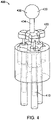
- FIG. 4 illustrates a portion of a contact-force-sensing system according to an embodiment .
- Contact-force-sensing system 400 can include force-receiving structure 430.
- Force-receiving structure 430 can be located along a central axis of the contact-force-sensing system 400.
- Force-receiving structure 430 can include ball 432, which can be connected to rod 434.
- Contact-force-sensing system 400 can also include a number of peripherally-located pressure-sensor chambers 410. Forces received by force-receiving structure 430 can be distributed through force-distribution structure 420 to the individual pressure-sensor chambers 410.
- Pressure-sensor chambers 410 can be filled with a fluid.
- Pressure-sensor chambers 410 can each include a pressure sensor. These pressure sensors can provide electrical signals to a computing device at an opposite and of a catheter or other medical device of which contact-force-sensing system 400 is included.
- forces acting upon force-receiving structure 430 can be distributed to the pressure-sensor chambers 410 through force-distribution structure 420.
- Force-distribution structure 420 can increase or decrease a pressure of a fluid in the pressure-sensor chambers 410. These changes in pressures can be registered by the pressure sensors located in pressure-sensor chambers 410. These changes in pressure can be used by the computing device at the opposite end to determine magnitude and direction information for the forces acting on force-receiving structure 430. From this information, the magnitude, angle, plane angle, and off plane angle information for these forces can be determined.
- Figure 5 illustrates another portion of a contact-force-sensing system according to an embodiment .
- This portion may include force-receiving structure 530 which can include a ball 532 and rod 534.
- Force-receiving structure 530 can be attached to force-distribution structure 520.
- Force-receiving structure 530 and force-distribution structure 520 can tilt about a central axis, defined in this example by rod 540.
- Force-distribution structure 520 can apply pressure to pressure-sensor chambers 410 (shown in Figure 4 ) via rods 524.
- Rod 524 can include spherical structures 522 that can pivot in openings in force-distribution structure 520 and the individual pressure-sensor chambers 410.
- Rod 540 can include spherical end 542 that can fit in an opening in force-distribution structure 520 to allow force-distribution structure 520 to tilt relative to rod 540.
- Figure 6 illustrates an example of forces received by a contact-force-sensing system according to an embodiment .
- forces F1, F2, and F3 can be inferred from changes in pressure sensors in pressure-sensor chambers. These changes in pressure can be used to determine a magnitude, angle, and off plane angle of the net force acting on a contact-force-sensing system.
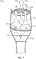
- Figure 7 illustrates another contact-force-sensing system according to an embodiment of .
- contact-force-sensing system 700 can be housed in housing 740 and can include force-receiving structure 730 that can directly encounter a cell wall or other structure during use.
- Force-receiving structure 730 can include a spherical end 732 attached to a plate 726 of force-distribution structure 720 through rod 734.
- Force-distribution structure 720 can further include rods 724 which can be driven by plate 726 to act upon pressure-sensor chambers 710.
- Pressure-sensor chambers 710 can be at least partially filled with a fluid and can contain pressure sensors 712. These pressure sensor chambers can be at least partially filled with a deformable material, such as an elastic rubber or polymer. Pressure sensors 712 can be attached to a computing device through wires 714. As before, rods 724 can include spherical ends 722 that can reside in openings in plate 726 thereby allowing plate 726 to tilt relative to the central axis of force sensing system 700.
- FIG. 8 illustrates another contact-force-sensing system according to an embodiment .
- pressure-sensor chambers 810 can be balloons that can be filled with a fluid, or an elastic or deformable material.
- Pressure-sensor chambers 810 can include pressure sensors 812 that can be attached to a remote computing device via wires 814.
- Pressure-sensor chambers 810 can be encased in a central pressure-sensor chamber 830.
- Electrodes 816 can be used to measure electrical signals of tissues that are encountered by this contact-force sensing system. Electrodes 816 can also or instead be used to apply currents, voltages, or both currents and voltages to these tissues. Electrodes 816 can be coupled to wires (not shown) that convey these signals to a distal end of this contact force sensing system.
- This configuration can allow a central pressure-sensor chamber 830 to measure a magnitude of a force on the contact-force-sensing system 800, while the individual peripherally-located pressure-sensor chambers 810 provide directional information.
- This configuration can also allow central pressure-sensor chamber 830 to be formed of a material that can conduct radio-frequency signals for heating during ablation and other procedures.
- Central pressure-sensor chamber 830 can alternatively or also be filled with a cryogenic liquid for use during these and other procedures.
- FIG. 9 illustrates another contact-force-sensing system according to an embodiment .
- contact-force-sensing system 900 can include a centrally-located pressure-sensor chamber 940 as well as a number of peripherally-located pressure-sensor chambers 910.
- the central and peripheral pressure-sensor chambers can each include a pressure sensor (not shown) which can be attached to a computer device through wires 914.
- Forces can be received by force-receiving structure 930. These forces can be distributed through force-distribution structure 920 to the peripherally-located pressure-sensor chambers 910 and centrally-located pressure-sensor chamber 940. A vertical force complement along a central axis of contact-force-sensing system 900 can act directly on centrally-located pressure-sensor chamber 940. This force can apply a compression force to a fluid in centrally-located pressure-sensor chamber 940. This compression force can be measured by a pressure sensor and used in determining the magnitude of a force received by force-receiving structure 930.
- Lateral force components acting laterally on force-receiving structure 930 can push force-distribution structure 920 into one or more of the peripherally-located pressure-sensor chambers 910. This in turn can increase or decrease forces on fluids in pressure-sensor chambers 910, which can result in a difference of pressure being measured by their individual pressure sensors. This information can then be used by the remote computing device to determine directional information for the forces received by force-receiving structure 930.
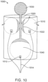
- FIG. 10 illustrates another contact-force-sensing system according to an embodiment .
- contact-force-sensing system 1000 can include force-receiving structure 1030 that can be connected to rod or force-distribution structure 1020.
- Force-distribution structure 1020 can include cupped surfaces 1022 that can be adjacent to balloons acting as peripherally-located pressure-sensor chambers 1010 and centrally-located pressure-sensor chamber 1040.
- the peripherally located pressure-sensor chamber 1010 and centrally-located pressure-sensor chamber 1040 can include pressure sensors 1012 can communicate with a computing device over wires 1014.
- the fluids in these various pressure-sensor chambers can be compressible or incompressible.
- they can be water, coconut water, olive oil, or other fluids or combinations of these or other fluids. They can be completely filled with these fluids or they can include one or more air bubbles. Examples are shown in the following figures.
- Figure 11 illustrates a portion of a contact-force-sensing system according to an embodiment .
- This example includes a force-receiving structure 1130 coupled to a force-distribution structure 1120. Forces received at force-receiving structure 1130 can act through force-distribution structure 1120 on pressure-sensor chamber 1110.
- Pressure-sensor chamber 1110 can include a pressure sensor 1112 that can communicate with a remote computing device over wires 1114.
- Pressure-sensor chamber 1110 can be filled with a fluid 1116.
- the fluid can include one or more air bubbles 1118.
- Pressure-sensor chamber 1110 and a portion of force-distribution structure 1120 can be located in housing 1150. In this example, the use of one or more air bubbles 1118 and the optional use of a possible fluid can prevent damage from being done to a thin membrane of pressure sensor 1112 during use.
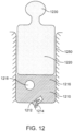
- Figure 12 illustrates a portion of a contact-force-sensing system according to an embodiment .
- This example includes a force-receiving structure 1230 coupled to a force-distribution structure 1220. Forces received at force-receiving structure 1230 can act through force-distribution structure 1220 on pressure-sensor chamber 1210.
- Pressure-sensor chamber 1210 can include a pressure sensor 1212 that can communicate with a remote computing device over wires 1214.
- Pressure-sensor chamber 1210 can be filled with a fluid 1216.
- the fluid can include one or more air bubbles 1218.
- Pressure-sensor chamber 1210 and a portion of force-distribution structure 1220 can be located in housing 1250. In this example, the use of one or more air bubbles 1218 and the optional use of a possible fluid can prevent damage from being done to a thin membrane of pressure sensor 1212 during use.
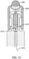
- Figure 13 illustrates a portion of a contact-force-sensing system according to an embodiment .
- This example includes a force-receiving structure 1330 which can apply force to a compressible material 1310 through a force-distribution structure 1320.
- Pressure sensor 1312 can be located in compressible material 1310 and can communicate with a remote computing device through wires 1314.
- these and similar principles can be used in other types of force sensing structures.
- these and other embodiments can provide a device that can determine a distribution of a force. An example is shown in the following figure.
- FIG. 14 illustrates a measuring device for determining a distribution of a force according to an embodiment .
- Measuring device 1400 can include a number of pressure-sensor chambers 1410 housed in housing 1420. Forces acting upon housing 1420 may, in turn, act upon pressure-sensor chambers 1410.
- Pressure-sensor chambers 1410 can include pressure sensors 1412 that can communicate with a remote computing device over wires 1414. Pressure-sensor chambers 1410 can be arrayed in one or more dimensions to determine a distribution of a force acting upon housing 1420.
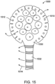
- FIG. 15 illustrates another contact-force-sensing system according to an embodiment.
- Contact-force-sensing system 1500 can include a balloon or other structure 1530 supporting a number of pressure-sensor chambers 1510.
- Pressure-sensor chambers 1510 can be attached to a surface of structure 1530.
- Pressure-sensor chambers 1510 can each include a corresponding pressure sensor 1512.
- Pressure sensor 1512 can communicate with a remote computing device over wires and electrodes 1514.
- Structure 1530 can be supported by stem 1532.
- pressure-sensor chambers 1510 can be attached to structure 1530.
- some or all of the pressure-sensor chambers 1510 can be formed by attaching a flexible layer over a structure. An example is shown in the following figure.
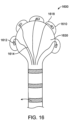
- FIG. 16 illustrates another contact-force-sensing system according to an embodiment.
- Contact-force-sensing system 1600 can include structure 1630 supporting a number of pressure-sensor chambers 1610.
- Pressure-sensor chambers 1610 can be formed by placing flexible layer 1618 over a portion of a surface of structure 1630.
- Pressure-sensor chambers 1610 can include pressure sensors 1612, which can communicate with a remote computing device over wires and electrodes 1614.
Landscapes
- Life Sciences & Earth Sciences (AREA)
- Health & Medical Sciences (AREA)
- Physics & Mathematics (AREA)
- Molecular Biology (AREA)
- Animal Behavior & Ethology (AREA)
- Pathology (AREA)
- Engineering & Computer Science (AREA)
- Biomedical Technology (AREA)
- Heart & Thoracic Surgery (AREA)
- Medical Informatics (AREA)
- Veterinary Medicine (AREA)
- Surgery (AREA)
- Biophysics (AREA)
- General Health & Medical Sciences (AREA)
- Public Health (AREA)
- General Physics & Mathematics (AREA)
- Force Measurement Appropriate To Specific Purposes (AREA)
- Medical Preparation Storing Or Oral Administration Devices (AREA)
- Surgical Instruments (AREA)
- Manipulator (AREA)
Claims (15)
- Kraftmesssystem für ein minimal-invasives medizinisches Gerät, wobei das Kraftmesssystem Folgendes umfasst:eine zentrale Achse (102); unddrei oder mehr Drucksensorkammern (110, 410, 710, 810, 910, 1010, 1110, 1210, 1510, 1610), die radial um die zentrale Achse (102) platziert sind, wobei jede Drucksensorkammer ein in der Kammer untergebrachtes Fluid (1116, 1216) und einen Drucksensor (712, 812, 1012, 1112, 1212, 1312, 1512, 1612) umfasst, der sich in jeder Drucksensorkammer befindet und so positioniert ist, dass er einen Druck auf das in jeder Drucksensorkammer untergebrachte Fluid (1116, 1216) erfasst.
- Kraftmesssystem nach Anspruch 1, das ferner ein mit der zentralen Achse (102) fluchtendes zentrales Element (434, 534, 734, 830, 920, 1020) umfasst, wobei das zentrale Element (434, 534, 734, 830, 920, 1020) in mindestens eine Richtung ausgelenkt werden kann.
- Kraftmesssystem nach Anspruch 2, wobei das zentrale Element (434, 534, 734, 830, 920, 1020) um einen zentralen Punkt ausgelenkt werden kann, wobei der zentrale Punkt mit der zentralen Achse (102) fluchtet, und wobei das zentrale Element, wenn es ausgelenkt wird, eine Kraft auf mindestens eine der drei oder mehr Drucksensorkammern (110, 410, 710, 810, 910, 1010, 1110, 1210, 1510, 1610) ausübt.
- Kraftmesssystem nach Anspruch 2 oder 3, wobei die Drucksensorkammern (810) Ballons (810) sind und das zentrale Element ein zentraler Ballon (830) ist, wobei sich die peripheren Ballons (810) in dem zentralen Ballon (830) befinden.
- Kraftmesssystem nach Anspruch 2 oder 3, wobei die drei oder mehr Drucksensorkammern (910) jeweils einen peripheren Ballon (910) umfassen und das zentrale Element einen zentralen Ballon (940) und einen Stab (920) umfasst, wobei der Stab (920) zum Auslenken konfiguriert ist, wobei der Stab (920), wenn er seitlich ausgelenkt wird, eine Kraft auf mindestens einen der peripheren Ballons (910) ausübt, und wobei der Stab (920), wenn er entlang der zentralen Achse (102) ausgelenkt wird, eine Kraft auf den zentralen Ballon (940) ausübt.
- Kraftmesssystem nach Anspruch 1, wobei jede Drucksensorkammer (810, 910v 1010) eine periphere Drucksensorkammer ist und das Kraftmesssystem ferner eine mit der zentralen Achse (102) fluchtende zentrale Drucksensorkammer (830, 940, 1040) umfasst, wobei die zentrale Drucksensorkammer ein in der Kammer untergebrachtes Fluid (1116, 1216) und einen Drucksensor (1112, 1212, 1312) umfasst, der zum Erfassen eines Drucks auf das Fluid in der Kammer positioniert ist.
- Kraftmesssystem nach Anspruch 6, wobei sich die peripheren Drucksensorkammern (810) innerhalb der zentralen Drucksensorkammer (830) befinden.
- Kraftmesssystem nach Anspruch 6, wobei sich die peripheren Drucksensorkammern (910, 1010) zwischen einer Vorderseite des Kraftmesssystems und der zentralen Drucksensorkammer (940, 1040) befinden.
- Kraftmesssystem nach Anspruch 6 oder 8, das ferner einen Stab (920, 1020) umfasst, wobei der Stab zum Auslenken konfiguriert ist, wobei der Stab, wenn er seitlich ausgelenkt wird, eine Kraft auf mindestens eine der peripheren Drucksensorkammern (910, 1010) ausübt, und wobei der Stab, wenn er entlang der zentralen Achse ausgelenkt wird, eine Kraft auf die zentrale Drucksensorkammer (940, 1040) ausübt.
- Kraftmesssystem nach einem der Ansprüche 6 bis 9, wobei die drei oder mehr peripheren Drucksensorkammern (810, 910, 1010) jeweils einen Ballon (810, 910, 1010) umfassen.
- Kraftmesssystem nach einem vorherigen Anspruch, wobei sich das Kraftmesssystem an einem distalen Ende eines Katheters oder einer nasogastralen Sonde befindet.
- Kraftmesssystem nach einem vorherigen Anspruch, wobei die Drucksensorkammern (110, 410, 710, 810, 910, 1010, 1110, 1210, 1510, 1610) mit Fluid gefüllt sind.
- Kraftmesssystem nach einem vorherigen Anspruch, wobei die Drucksensorkammern (110, 410, 710, 810, 910, 1010, 1110, 1210, 1510, 1610) ein inkompressibles Fluid enthalten.
- Kraftmesssystem nach einem vorherigen Anspruch, wobei das Fluid in den Drucksensorkammern eine oder mehrere Luftblasen enthält.
- Kraftmesssystem nach einem vorherigen Anspruch, das ferner Druckkanäle (240, 340) umfasst, die sich zwischen einem distalen Ende des Kraftmesssystems und einem proximalen Ende erstrecken, wobei die Druckkanäle (240, 340) zum Verteilen der Kraft von Aufnahmestrukturen (230, 330, 270, 370) über eine Kraftverteilungsstruktur konfiguriert sind.
Applications Claiming Priority (2)
| Application Number | Priority Date | Filing Date | Title |
|---|---|---|---|
| US201962813683P | 2019-03-04 | 2019-03-04 | |
| US16/513,561 US11454561B2 (en) | 2019-03-04 | 2019-07-16 | 3D contact force sensing |
Publications (2)
| Publication Number | Publication Date |
|---|---|
| EP3705030A1 EP3705030A1 (de) | 2020-09-09 |
| EP3705030B1 true EP3705030B1 (de) | 2023-04-05 |
Family
ID=69953733
Family Applications (1)
| Application Number | Title | Priority Date | Filing Date |
|---|---|---|---|
| EP20160553.2A Active EP3705030B1 (de) | 2019-03-04 | 2020-03-03 | 3d-kontaktkraftmessung |
Country Status (4)
| Country | Link |
|---|---|
| US (1) | US11454561B2 (de) |
| EP (1) | EP3705030B1 (de) |
| JP (1) | JP7562957B2 (de) |
| CN (1) | CN111649859A (de) |
Families Citing this family (3)
| Publication number | Priority date | Publication date | Assignee | Title |
|---|---|---|---|---|
| CN113063537B (zh) * | 2021-03-17 | 2022-09-09 | 重庆大学 | 多维力传感器恒温系统及其控制算法 |
| CN113599274B (zh) * | 2021-09-13 | 2023-11-03 | 郑州大学第一附属医院 | 一种食管癌用的营养液输送装置 |
| CN116849812A (zh) * | 2023-07-05 | 2023-10-10 | 西安交通大学医学院第一附属医院 | 一种磁引导式鼻胃管置管机器人系统 |
Family Cites Families (14)
| Publication number | Priority date | Publication date | Assignee | Title |
|---|---|---|---|---|
| JPS4826553B1 (de) * | 1968-10-24 | 1973-08-11 | ||
| IL116699A (en) | 1996-01-08 | 2001-09-13 | Biosense Ltd | Method of building a heart map |
| JP4387691B2 (ja) * | 2003-04-28 | 2009-12-16 | 株式会社ワコー | 力検出装置 |
| US8048063B2 (en) | 2006-06-09 | 2011-11-01 | Endosense Sa | Catheter having tri-axial force sensor |
| EP2122318A2 (de) | 2007-03-07 | 2009-11-25 | Koninklijke Philips Electronics N.V. | Medizinische vorrichtung mit einem sensor zur krafterkennung |
| US8192368B2 (en) * | 2008-06-09 | 2012-06-05 | Gentera Holdings, Llc | Pressure sensing catheter |
| EP2459058B1 (de) * | 2009-07-29 | 2014-12-31 | Mayo Foundation For Medical Education And Research | Systeme und vorrichtungen zur beurteilung von körperhöhlendruck |
| KR101194009B1 (ko) * | 2010-03-23 | 2012-10-24 | 포테닛 주식회사 | 3축 방향 힘 측정장치 |
| US8226580B2 (en) * | 2010-06-30 | 2012-07-24 | Biosense Webster (Israel), Ltd. | Pressure sensing for a multi-arm catheter |
| US20130274712A1 (en) * | 2011-11-02 | 2013-10-17 | Stuart O. Schecter | Haptic system for balloon tipped catheter interventions |
| EP2617456A1 (de) * | 2012-01-19 | 2013-07-24 | VascoMed GmbH | Katheter und Katheteranordnung |
| EP3294135A4 (de) * | 2015-05-12 | 2019-01-09 | Mir Imran | Vorrichtung, system und verfahren zur druckmessung im harntrakt |
| US10383543B2 (en) | 2015-11-11 | 2019-08-20 | Biosense Webster (Israel) Ltd. | Symmetric short contact force sensor with four coils |
| WO2018150314A1 (en) | 2017-02-15 | 2018-08-23 | St. Jude Medical International Holding S.À R.L | Catheter tip force sensor |
-
2019
- 2019-07-16 US US16/513,561 patent/US11454561B2/en active Active
-
2020
- 2020-02-27 JP JP2020031321A patent/JP7562957B2/ja active Active
- 2020-03-03 EP EP20160553.2A patent/EP3705030B1/de active Active
- 2020-03-04 CN CN202010142217.1A patent/CN111649859A/zh active Pending
Also Published As
| Publication number | Publication date |
|---|---|
| EP3705030A1 (de) | 2020-09-09 |
| JP7562957B2 (ja) | 2024-10-08 |
| CN111649859A (zh) | 2020-09-11 |
| US20200284675A1 (en) | 2020-09-10 |
| JP2020144118A (ja) | 2020-09-10 |
| US11454561B2 (en) | 2022-09-27 |
Similar Documents
| Publication | Publication Date | Title |
|---|---|---|
| EP2945561B1 (de) | Elektrodenkontaktrückkopplungssystem | |
| ES2467415T3 (es) | Catéter con detección de presión | |
| EP3705030A1 (de) | 3d-kontaktkraftmessung | |
| ES2336477T3 (es) | Deteccion de posicion hibrida basada en el magnetismo y la impedancia. | |
| US8380276B2 (en) | Catheter with thin film pressure sensing distal tip | |
| EP3677206B1 (de) | Medizinprodukt mit mehradriger faser für optische messung | |
| ES2448366T3 (es) | Sistema de calibración para un cateter sensible a la presión | |
| JP5722017B2 (ja) | 接触情報を用いたプローブデータのマッピング | |
| US9033896B2 (en) | Obtaining a tissue sample | |
| JP6180634B2 (ja) | 接触力感知用先端を有する医療デバイス | |
| US7611482B2 (en) | Minimally-invasive smart devices | |
| US20050187467A1 (en) | Catheter | |
| JP2018171444A (ja) | 大領域の電極を具備するバルーンカテーテル | |
| US20100069733A1 (en) | Electrophysiology catheter with electrode loop | |
| US11871900B2 (en) | Instrument comprising a contact force sensor device | |
| EP4079365B1 (de) | Elektrophysiologievorrichtungen mit ablenkdetektion | |
| CN116602652A (zh) | 在插入期间检测组织阻力的探针 | |
| US20250228542A1 (en) | Multipurpose medical device | |
| US20170258540A1 (en) | Control system for elongate instrument | |
| US20130190730A1 (en) | Catheter and catheter system |
Legal Events
| Date | Code | Title | Description |
|---|---|---|---|
| PUAI | Public reference made under article 153(3) epc to a published international application that has entered the european phase |
Free format text: ORIGINAL CODE: 0009012 |
|
| STAA | Information on the status of an ep patent application or granted ep patent |
Free format text: STATUS: THE APPLICATION HAS BEEN PUBLISHED |
|
| AK | Designated contracting states |
Kind code of ref document: A1 Designated state(s): AL AT BE BG CH CY CZ DE DK EE ES FI FR GB GR HR HU IE IS IT LI LT LU LV MC MK MT NL NO PL PT RO RS SE SI SK SM TR |
|
| AX | Request for extension of the european patent |
Extension state: BA ME |
|
| STAA | Information on the status of an ep patent application or granted ep patent |
Free format text: STATUS: REQUEST FOR EXAMINATION WAS MADE |
|
| 17P | Request for examination filed |
Effective date: 20210203 |
|
| RBV | Designated contracting states (corrected) |
Designated state(s): AL AT BE BG CH CY CZ DE DK EE ES FI FR GB GR HR HU IE IS IT LI LT LU LV MC MK MT NL NO PL PT RO RS SE SI SK SM TR |
|
| RAP1 | Party data changed (applicant data changed or rights of an application transferred) |
Owner name: MEASUREMENT SPECIALTIES, INC. |
|
| GRAP | Despatch of communication of intention to grant a patent |
Free format text: ORIGINAL CODE: EPIDOSNIGR1 |
|
| STAA | Information on the status of an ep patent application or granted ep patent |
Free format text: STATUS: GRANT OF PATENT IS INTENDED |
|
| INTG | Intention to grant announced |
Effective date: 20221202 |
|
| GRAS | Grant fee paid |
Free format text: ORIGINAL CODE: EPIDOSNIGR3 |
|
| GRAJ | Information related to disapproval of communication of intention to grant by the applicant or resumption of examination proceedings by the epo deleted |
Free format text: ORIGINAL CODE: EPIDOSDIGR1 |
|
| GRAL | Information related to payment of fee for publishing/printing deleted |
Free format text: ORIGINAL CODE: EPIDOSDIGR3 |
|
| STAA | Information on the status of an ep patent application or granted ep patent |
Free format text: STATUS: REQUEST FOR EXAMINATION WAS MADE |
|
| GRAP | Despatch of communication of intention to grant a patent |
Free format text: ORIGINAL CODE: EPIDOSNIGR1 |
|
| STAA | Information on the status of an ep patent application or granted ep patent |
Free format text: STATUS: GRANT OF PATENT IS INTENDED |
|
| INTC | Intention to grant announced (deleted) | ||
| GRAA | (expected) grant |
Free format text: ORIGINAL CODE: 0009210 |
|
| STAA | Information on the status of an ep patent application or granted ep patent |
Free format text: STATUS: THE PATENT HAS BEEN GRANTED |
|
| INTG | Intention to grant announced |
Effective date: 20230215 |
|
| AK | Designated contracting states |
Kind code of ref document: B1 Designated state(s): AL AT BE BG CH CY CZ DE DK EE ES FI FR GB GR HR HU IE IS IT LI LT LU LV MC MK MT NL NO PL PT RO RS SE SI SK SM TR |
|
| REG | Reference to a national code |
Ref country code: GB Ref legal event code: FG4D |
|
| REG | Reference to a national code |
Ref country code: DE Ref legal event code: R096 Ref document number: 602020009356 Country of ref document: DE |
|
| REG | Reference to a national code |
Ref country code: CH Ref legal event code: EP |
|
| REG | Reference to a national code |
Ref country code: AT Ref legal event code: REF Ref document number: 1557650 Country of ref document: AT Kind code of ref document: T Effective date: 20230415 |
|
| REG | Reference to a national code |
Ref country code: IE Ref legal event code: FG4D |
|
| REG | Reference to a national code |
Ref country code: LT Ref legal event code: MG9D |
|
| REG | Reference to a national code |
Ref country code: NL Ref legal event code: MP Effective date: 20230405 |
|
| REG | Reference to a national code |
Ref country code: AT Ref legal event code: MK05 Ref document number: 1557650 Country of ref document: AT Kind code of ref document: T Effective date: 20230405 |
|
| PG25 | Lapsed in a contracting state [announced via postgrant information from national office to epo] |
Ref country code: NL Free format text: LAPSE BECAUSE OF FAILURE TO SUBMIT A TRANSLATION OF THE DESCRIPTION OR TO PAY THE FEE WITHIN THE PRESCRIBED TIME-LIMIT Effective date: 20230405 |
|
| PG25 | Lapsed in a contracting state [announced via postgrant information from national office to epo] |
Ref country code: SE Free format text: LAPSE BECAUSE OF FAILURE TO SUBMIT A TRANSLATION OF THE DESCRIPTION OR TO PAY THE FEE WITHIN THE PRESCRIBED TIME-LIMIT Effective date: 20230405 Ref country code: PT Free format text: LAPSE BECAUSE OF FAILURE TO SUBMIT A TRANSLATION OF THE DESCRIPTION OR TO PAY THE FEE WITHIN THE PRESCRIBED TIME-LIMIT Effective date: 20230807 Ref country code: NO Free format text: LAPSE BECAUSE OF FAILURE TO SUBMIT A TRANSLATION OF THE DESCRIPTION OR TO PAY THE FEE WITHIN THE PRESCRIBED TIME-LIMIT Effective date: 20230705 Ref country code: ES Free format text: LAPSE BECAUSE OF FAILURE TO SUBMIT A TRANSLATION OF THE DESCRIPTION OR TO PAY THE FEE WITHIN THE PRESCRIBED TIME-LIMIT Effective date: 20230405 Ref country code: AT Free format text: LAPSE BECAUSE OF FAILURE TO SUBMIT A TRANSLATION OF THE DESCRIPTION OR TO PAY THE FEE WITHIN THE PRESCRIBED TIME-LIMIT Effective date: 20230405 |
|
| PG25 | Lapsed in a contracting state [announced via postgrant information from national office to epo] |
Ref country code: RS Free format text: LAPSE BECAUSE OF FAILURE TO SUBMIT A TRANSLATION OF THE DESCRIPTION OR TO PAY THE FEE WITHIN THE PRESCRIBED TIME-LIMIT Effective date: 20230405 Ref country code: PL Free format text: LAPSE BECAUSE OF FAILURE TO SUBMIT A TRANSLATION OF THE DESCRIPTION OR TO PAY THE FEE WITHIN THE PRESCRIBED TIME-LIMIT Effective date: 20230405 Ref country code: LV Free format text: LAPSE BECAUSE OF FAILURE TO SUBMIT A TRANSLATION OF THE DESCRIPTION OR TO PAY THE FEE WITHIN THE PRESCRIBED TIME-LIMIT Effective date: 20230405 Ref country code: LT Free format text: LAPSE BECAUSE OF FAILURE TO SUBMIT A TRANSLATION OF THE DESCRIPTION OR TO PAY THE FEE WITHIN THE PRESCRIBED TIME-LIMIT Effective date: 20230405 Ref country code: IS Free format text: LAPSE BECAUSE OF FAILURE TO SUBMIT A TRANSLATION OF THE DESCRIPTION OR TO PAY THE FEE WITHIN THE PRESCRIBED TIME-LIMIT Effective date: 20230805 Ref country code: HR Free format text: LAPSE BECAUSE OF FAILURE TO SUBMIT A TRANSLATION OF THE DESCRIPTION OR TO PAY THE FEE WITHIN THE PRESCRIBED TIME-LIMIT Effective date: 20230405 Ref country code: GR Free format text: LAPSE BECAUSE OF FAILURE TO SUBMIT A TRANSLATION OF THE DESCRIPTION OR TO PAY THE FEE WITHIN THE PRESCRIBED TIME-LIMIT Effective date: 20230706 Ref country code: AL Free format text: LAPSE BECAUSE OF FAILURE TO SUBMIT A TRANSLATION OF THE DESCRIPTION OR TO PAY THE FEE WITHIN THE PRESCRIBED TIME-LIMIT Effective date: 20230405 |
|
| PG25 | Lapsed in a contracting state [announced via postgrant information from national office to epo] |
Ref country code: FI Free format text: LAPSE BECAUSE OF FAILURE TO SUBMIT A TRANSLATION OF THE DESCRIPTION OR TO PAY THE FEE WITHIN THE PRESCRIBED TIME-LIMIT Effective date: 20230405 |
|
| REG | Reference to a national code |
Ref country code: DE Ref legal event code: R097 Ref document number: 602020009356 Country of ref document: DE |
|
| PG25 | Lapsed in a contracting state [announced via postgrant information from national office to epo] |
Ref country code: SK Free format text: LAPSE BECAUSE OF FAILURE TO SUBMIT A TRANSLATION OF THE DESCRIPTION OR TO PAY THE FEE WITHIN THE PRESCRIBED TIME-LIMIT Effective date: 20230405 |
|
| PG25 | Lapsed in a contracting state [announced via postgrant information from national office to epo] |
Ref country code: SM Free format text: LAPSE BECAUSE OF FAILURE TO SUBMIT A TRANSLATION OF THE DESCRIPTION OR TO PAY THE FEE WITHIN THE PRESCRIBED TIME-LIMIT Effective date: 20230405 Ref country code: SK Free format text: LAPSE BECAUSE OF FAILURE TO SUBMIT A TRANSLATION OF THE DESCRIPTION OR TO PAY THE FEE WITHIN THE PRESCRIBED TIME-LIMIT Effective date: 20230405 Ref country code: RO Free format text: LAPSE BECAUSE OF FAILURE TO SUBMIT A TRANSLATION OF THE DESCRIPTION OR TO PAY THE FEE WITHIN THE PRESCRIBED TIME-LIMIT Effective date: 20230405 Ref country code: EE Free format text: LAPSE BECAUSE OF FAILURE TO SUBMIT A TRANSLATION OF THE DESCRIPTION OR TO PAY THE FEE WITHIN THE PRESCRIBED TIME-LIMIT Effective date: 20230405 Ref country code: DK Free format text: LAPSE BECAUSE OF FAILURE TO SUBMIT A TRANSLATION OF THE DESCRIPTION OR TO PAY THE FEE WITHIN THE PRESCRIBED TIME-LIMIT Effective date: 20230405 Ref country code: CZ Free format text: LAPSE BECAUSE OF FAILURE TO SUBMIT A TRANSLATION OF THE DESCRIPTION OR TO PAY THE FEE WITHIN THE PRESCRIBED TIME-LIMIT Effective date: 20230405 |
|
| PLBE | No opposition filed within time limit |
Free format text: ORIGINAL CODE: 0009261 |
|
| STAA | Information on the status of an ep patent application or granted ep patent |
Free format text: STATUS: NO OPPOSITION FILED WITHIN TIME LIMIT |
|
| 26N | No opposition filed |
Effective date: 20240108 |
|
| PG25 | Lapsed in a contracting state [announced via postgrant information from national office to epo] |
Ref country code: SI Free format text: LAPSE BECAUSE OF FAILURE TO SUBMIT A TRANSLATION OF THE DESCRIPTION OR TO PAY THE FEE WITHIN THE PRESCRIBED TIME-LIMIT Effective date: 20230405 |
|
| PG25 | Lapsed in a contracting state [announced via postgrant information from national office to epo] |
Ref country code: SI Free format text: LAPSE BECAUSE OF FAILURE TO SUBMIT A TRANSLATION OF THE DESCRIPTION OR TO PAY THE FEE WITHIN THE PRESCRIBED TIME-LIMIT Effective date: 20230405 Ref country code: IT Free format text: LAPSE BECAUSE OF FAILURE TO SUBMIT A TRANSLATION OF THE DESCRIPTION OR TO PAY THE FEE WITHIN THE PRESCRIBED TIME-LIMIT Effective date: 20230405 |
|
| REG | Reference to a national code |
Ref country code: CH Ref legal event code: PL |
|
| PG25 | Lapsed in a contracting state [announced via postgrant information from national office to epo] |
Ref country code: BG Free format text: LAPSE BECAUSE OF FAILURE TO SUBMIT A TRANSLATION OF THE DESCRIPTION OR TO PAY THE FEE WITHIN THE PRESCRIBED TIME-LIMIT Effective date: 20230405 |
|
| PG25 | Lapsed in a contracting state [announced via postgrant information from national office to epo] |
Ref country code: LU Free format text: LAPSE BECAUSE OF NON-PAYMENT OF DUE FEES Effective date: 20240303 |
|
| PG25 | Lapsed in a contracting state [announced via postgrant information from national office to epo] |
Ref country code: MC Free format text: LAPSE BECAUSE OF FAILURE TO SUBMIT A TRANSLATION OF THE DESCRIPTION OR TO PAY THE FEE WITHIN THE PRESCRIBED TIME-LIMIT Effective date: 20230405 |
|
| GBPC | Gb: european patent ceased through non-payment of renewal fee |
Effective date: 20240303 |
|
| PG25 | Lapsed in a contracting state [announced via postgrant information from national office to epo] |
Ref country code: MC Free format text: LAPSE BECAUSE OF FAILURE TO SUBMIT A TRANSLATION OF THE DESCRIPTION OR TO PAY THE FEE WITHIN THE PRESCRIBED TIME-LIMIT Effective date: 20230405 Ref country code: LU Free format text: LAPSE BECAUSE OF NON-PAYMENT OF DUE FEES Effective date: 20240303 Ref country code: BG Free format text: LAPSE BECAUSE OF FAILURE TO SUBMIT A TRANSLATION OF THE DESCRIPTION OR TO PAY THE FEE WITHIN THE PRESCRIBED TIME-LIMIT Effective date: 20230405 |
|
| REG | Reference to a national code |
Ref country code: BE Ref legal event code: MM Effective date: 20240331 |
|
| PG25 | Lapsed in a contracting state [announced via postgrant information from national office to epo] |
Ref country code: BE Free format text: LAPSE BECAUSE OF NON-PAYMENT OF DUE FEES Effective date: 20240331 |
|
| PG25 | Lapsed in a contracting state [announced via postgrant information from national office to epo] |
Ref country code: GB Free format text: LAPSE BECAUSE OF NON-PAYMENT OF DUE FEES Effective date: 20240303 |
|
| PGFP | Annual fee paid to national office [announced via postgrant information from national office to epo] |
Ref country code: FR Payment date: 20241231 Year of fee payment: 6 |
|
| PG25 | Lapsed in a contracting state [announced via postgrant information from national office to epo] |
Ref country code: IE Free format text: LAPSE BECAUSE OF NON-PAYMENT OF DUE FEES Effective date: 20240303 |
|
| PG25 | Lapsed in a contracting state [announced via postgrant information from national office to epo] |
Ref country code: IE Free format text: LAPSE BECAUSE OF NON-PAYMENT OF DUE FEES Effective date: 20240303 Ref country code: GB Free format text: LAPSE BECAUSE OF NON-PAYMENT OF DUE FEES Effective date: 20240303 Ref country code: BE Free format text: LAPSE BECAUSE OF NON-PAYMENT OF DUE FEES Effective date: 20240331 Ref country code: CH Free format text: LAPSE BECAUSE OF NON-PAYMENT OF DUE FEES Effective date: 20240331 |
|
| PG25 | Lapsed in a contracting state [announced via postgrant information from national office to epo] |
Ref country code: CY Free format text: LAPSE BECAUSE OF FAILURE TO SUBMIT A TRANSLATION OF THE DESCRIPTION OR TO PAY THE FEE WITHIN THE PRESCRIBED TIME-LIMIT; INVALID AB INITIO Effective date: 20200303 |
|
| PG25 | Lapsed in a contracting state [announced via postgrant information from national office to epo] |
Ref country code: HU Free format text: LAPSE BECAUSE OF FAILURE TO SUBMIT A TRANSLATION OF THE DESCRIPTION OR TO PAY THE FEE WITHIN THE PRESCRIBED TIME-LIMIT; INVALID AB INITIO Effective date: 20200303 |
|
| PG25 | Lapsed in a contracting state [announced via postgrant information from national office to epo] |
Ref country code: TR Free format text: LAPSE BECAUSE OF FAILURE TO SUBMIT A TRANSLATION OF THE DESCRIPTION OR TO PAY THE FEE WITHIN THE PRESCRIBED TIME-LIMIT Effective date: 20230405 |
|
| PGFP | Annual fee paid to national office [announced via postgrant information from national office to epo] |
Ref country code: DE Payment date: 20260102 Year of fee payment: 7 |