EP3704986A1 - Einlegesohle und schuhe damit - Google Patents
Einlegesohle und schuhe damit Download PDFInfo
- Publication number
- EP3704986A1 EP3704986A1 EP19214921.9A EP19214921A EP3704986A1 EP 3704986 A1 EP3704986 A1 EP 3704986A1 EP 19214921 A EP19214921 A EP 19214921A EP 3704986 A1 EP3704986 A1 EP 3704986A1
- Authority
- EP
- European Patent Office
- Prior art keywords
- base
- cover
- controller
- electronic element
- insole
- Prior art date
- Legal status (The legal status is an assumption and is not a legal conclusion. Google has not performed a legal analysis and makes no representation as to the accuracy of the status listed.)
- Granted
Links
Images


Classifications
-
- A—HUMAN NECESSITIES
- A43—FOOTWEAR
- A43B—CHARACTERISTIC FEATURES OF FOOTWEAR; PARTS OF FOOTWEAR
- A43B17/00—Insoles for insertion, e.g. footbeds or inlays, for attachment to the shoe after the upper has been joined
-
- A—HUMAN NECESSITIES
- A43—FOOTWEAR
- A43B—CHARACTERISTIC FEATURES OF FOOTWEAR; PARTS OF FOOTWEAR
- A43B13/00—Soles; Sole-and-heel integral units
-
- A—HUMAN NECESSITIES
- A43—FOOTWEAR
- A43B—CHARACTERISTIC FEATURES OF FOOTWEAR; PARTS OF FOOTWEAR
- A43B13/00—Soles; Sole-and-heel integral units
- A43B13/02—Soles; Sole-and-heel integral units characterised by the material
- A43B13/12—Soles with several layers of different materials
- A43B13/125—Soles with several layers of different materials characterised by the midsole or middle layer
-
- A—HUMAN NECESSITIES
- A43—FOOTWEAR
- A43B—CHARACTERISTIC FEATURES OF FOOTWEAR; PARTS OF FOOTWEAR
- A43B13/00—Soles; Sole-and-heel integral units
- A43B13/14—Soles; Sole-and-heel integral units characterised by the constructive form
-
- A—HUMAN NECESSITIES
- A43—FOOTWEAR
- A43B—CHARACTERISTIC FEATURES OF FOOTWEAR; PARTS OF FOOTWEAR
- A43B13/00—Soles; Sole-and-heel integral units
- A43B13/14—Soles; Sole-and-heel integral units characterised by the constructive form
- A43B13/141—Soles; Sole-and-heel integral units characterised by the constructive form with a part of the sole being flexible, e.g. permitting articulation or torsion
-
- A—HUMAN NECESSITIES
- A43—FOOTWEAR
- A43B—CHARACTERISTIC FEATURES OF FOOTWEAR; PARTS OF FOOTWEAR
- A43B13/00—Soles; Sole-and-heel integral units
- A43B13/37—Sole and heel units
-
- A—HUMAN NECESSITIES
- A43—FOOTWEAR
- A43B—CHARACTERISTIC FEATURES OF FOOTWEAR; PARTS OF FOOTWEAR
- A43B13/00—Soles; Sole-and-heel integral units
- A43B13/38—Built-in insoles joined to uppers during the manufacturing process, e.g. structural insoles; Insoles glued to shoes during the manufacturing process
-
- A—HUMAN NECESSITIES
- A43—FOOTWEAR
- A43B—CHARACTERISTIC FEATURES OF FOOTWEAR; PARTS OF FOOTWEAR
- A43B17/00—Insoles for insertion, e.g. footbeds or inlays, for attachment to the shoe after the upper has been joined
- A43B17/18—Arrangements for attaching removable insoles to footwear
-
- A—HUMAN NECESSITIES
- A43—FOOTWEAR
- A43B—CHARACTERISTIC FEATURES OF FOOTWEAR; PARTS OF FOOTWEAR
- A43B23/00—Uppers; Boot legs; Stiffeners; Other single parts of footwear
- A43B23/02—Uppers; Boot legs
- A43B23/0245—Uppers; Boot legs characterised by the constructive form
-
- A—HUMAN NECESSITIES
- A43—FOOTWEAR
- A43B—CHARACTERISTIC FEATURES OF FOOTWEAR; PARTS OF FOOTWEAR
- A43B3/00—Footwear characterised by the shape or the use
- A43B3/34—Footwear characterised by the shape or the use with electrical or electronic arrangements
-
- A—HUMAN NECESSITIES
- A43—FOOTWEAR
- A43B—CHARACTERISTIC FEATURES OF FOOTWEAR; PARTS OF FOOTWEAR
- A43B3/00—Footwear characterised by the shape or the use
- A43B3/34—Footwear characterised by the shape or the use with electrical or electronic arrangements
- A43B3/38—Footwear characterised by the shape or the use with electrical or electronic arrangements with power sources
-
- A—HUMAN NECESSITIES
- A61—MEDICAL OR VETERINARY SCIENCE; HYGIENE
- A61B—DIAGNOSIS; SURGERY; IDENTIFICATION
- A61B5/00—Measuring for diagnostic purposes; Identification of persons
- A61B5/103—Measuring devices for testing the shape, pattern, colour, size or movement of the body or parts thereof, for diagnostic purposes
- A61B5/1036—Measuring load distribution, e.g. podologic studies
- A61B5/1038—Measuring plantar pressure during gait
-
- A—HUMAN NECESSITIES
- A61—MEDICAL OR VETERINARY SCIENCE; HYGIENE
- A61B—DIAGNOSIS; SURGERY; IDENTIFICATION
- A61B5/00—Measuring for diagnostic purposes; Identification of persons
- A61B5/103—Measuring devices for testing the shape, pattern, colour, size or movement of the body or parts thereof, for diagnostic purposes
- A61B5/11—Measuring movement of the entire body or parts thereof, e.g. head or hand tremor or mobility of a limb
- A61B5/112—Gait analysis
-
- A—HUMAN NECESSITIES
- A61—MEDICAL OR VETERINARY SCIENCE; HYGIENE
- A61B—DIAGNOSIS; SURGERY; IDENTIFICATION
- A61B5/00—Measuring for diagnostic purposes; Identification of persons
- A61B5/68—Arrangements of detecting, measuring or recording means, e.g. sensors, in relation to patient
- A61B5/6801—Arrangements of detecting, measuring or recording means, e.g. sensors, in relation to patient specially adapted to be attached to or worn on the body surface
- A61B5/6802—Sensor mounted on worn items
- A61B5/6804—Garments; Clothes
- A61B5/6807—Footwear
-
- G—PHYSICS
- G01—MEASURING; TESTING
- G01D—MEASURING NOT SPECIALLY ADAPTED FOR A SPECIFIC VARIABLE; ARRANGEMENTS FOR MEASURING TWO OR MORE VARIABLES NOT COVERED IN A SINGLE OTHER SUBCLASS; TARIFF METERING APPARATUS; MEASURING OR TESTING NOT OTHERWISE PROVIDED FOR
- G01D21/00—Measuring or testing not otherwise provided for
- G01D21/02—Measuring two or more variables by means not covered by a single other subclass
-
- G—PHYSICS
- G01—MEASURING; TESTING
- G01K—MEASURING TEMPERATURE; MEASURING QUANTITY OF HEAT; THERMALLY-SENSITIVE ELEMENTS NOT OTHERWISE PROVIDED FOR
- G01K1/00—Details of thermometers not specially adapted for particular types of thermometer
- G01K1/14—Supports; Fastening devices; Arrangements for mounting thermometers in particular locations
-
- G—PHYSICS
- G01—MEASURING; TESTING
- G01L—MEASURING FORCE, STRESS, TORQUE, WORK, MECHANICAL POWER, MECHANICAL EFFICIENCY, OR FLUID PRESSURE
- G01L5/00—Apparatus for, or methods of, measuring force, work, mechanical power, or torque, specially adapted for specific purposes
- G01L5/0028—Force sensors associated with force applying means
-
- G—PHYSICS
- G01—MEASURING; TESTING
- G01P—MEASURING LINEAR OR ANGULAR SPEED, ACCELERATION, DECELERATION, OR SHOCK; INDICATING PRESENCE, ABSENCE, OR DIRECTION, OF MOVEMENT
- G01P15/00—Measuring acceleration; Measuring deceleration; Measuring shock, i.e. sudden change of acceleration
- G01P15/02—Measuring acceleration; Measuring deceleration; Measuring shock, i.e. sudden change of acceleration by making use of inertia forces using solid seismic masses
-
- A—HUMAN NECESSITIES
- A61—MEDICAL OR VETERINARY SCIENCE; HYGIENE
- A61B—DIAGNOSIS; SURGERY; IDENTIFICATION
- A61B2562/00—Details of sensors; Constructional details of sensor housings or probes; Accessories for sensors
- A61B2562/02—Details of sensors specially adapted for in-vivo measurements
- A61B2562/0219—Inertial sensors, e.g. accelerometers, gyroscopes, tilt switches
-
- A—HUMAN NECESSITIES
- A61—MEDICAL OR VETERINARY SCIENCE; HYGIENE
- A61B—DIAGNOSIS; SURGERY; IDENTIFICATION
- A61B2562/00—Details of sensors; Constructional details of sensor housings or probes; Accessories for sensors
- A61B2562/22—Arrangements of medical sensors with cables or leads; Connectors or couplings specifically adapted for medical sensors
- A61B2562/225—Connectors or couplings
- A61B2562/227—Sensors with electrical connectors
Definitions
- Some example embodiments relate to an insole and/or shoes including the insole.
- a user wears shoes in daily life. Shoes protect feet of the user comfortably and safely.
- wearable devices are developed to detect a gait pattern of the user and to assist the user to stably walk by providing a sensor and/or a driver to a shoe.
- Some example embodiments relate to an insole.
- the insole includes a base; an electronic element provided to the base; a connection line extending from the electronic element and passing through the base; and a cover configured to detachably connect to a top surface of the base such that the cover covers the electronic element when the cover is connected to the base.
- the base includes a base body configured to support the electronic element; and a base protrusion protruding from the base body, the base protrusion configured to connect to the cover such that the electronic element supported by the base body is surrounded by the base protrusion.
- a support layer configured to support the electronic element and the connection line and to be fitted to an inside of the base protrusion.
- the base body has a base hole passing therethrough such that a front sidewall of the base hole is sloped rearward and downward from the base body to form a guide.
- the support layer includes a layer body configured to rest on the top surface of the base, the connection line extending along a top surface of the layer body; and a ramp formed on a central portion of the layer body, the ramp having a slope corresponding to a slope of the guide such that the connection line runs along the ramp and passes through the base.
- the electronic element comprises a plurality of electronic devices including, a front electronic device configured to overlap a forefoot of a user based on a direction perpendicular to the base; and a rear electronic device configured to overlap a rear foot of the user based on the direction perpendicular to the base.
- the base hole in the base body is at a position corresponding to a location between the front electronic device and the rear electronic device.
- the cover includes a cover body including a cover groove configured to receive the base protrusion; and a cover protrusion configured to protrude from the cover body and to press against the support layer.
- the insole further includes a controller insertable into the base and provided on the opposite side of the electronic element respect to the base.
- the controller includes a controller body having a controller protrusion extending rearward from the controller body, such that the controller is insertable into the base by inserting the controller in a main groove in the base such that the controller protrusion penetrates an auxiliary groove within the main groove, the auxiliary groove recessed from one side surface of the main groove toward the rear portion of the base.
- the insert including a more rigid material than that of the base, wherein the controller and the insert are configured to be combinable in a state in which the connection line is between the controller and the insert.
- the electronic element includes at least one electronic device including a vibrator, a pressure sensor, a temperature sensor, or an inertial sensor.
- Some example embodiments relate to a shoe.
- the shoe includes a midsole; an upper on a top surface of the midsole; and an insole including, a base insertable into the upper, an electronic element including a connection line, the electronic element insertable in the base such that the connection line extends from the electronic element and passes through the base, and a cover configured to detachably connect to a top surface of the base such that the cover covers the electronic element when the cover is connected to the base.
- the insole further includes a controller insertable into the base such that, when the electronic element is inserted into the base, the controller is connected to the connection line.
- the shoe further includes an interface attached to an exterior of one of the upper and the midsole, the interface configured to connect to the controller.
- the interface includes an interface body configured to fasten to the midsole; an interface cover including a power terminal, the interface cover detachably connected to the interface body; and a connector configured to pass through the upper and connect the power terminal to the controller.
- the interface body includes a body magnet having a first polarity
- the interface cover further includes a cover magnet configured to face the body magnet, the cover magnet having a second polarity opposite the first polarity
- the base includes a base body configured to support the electronic element; and a base protrusion protruding from the base body, the base protrusion configured to connect to the cover such that the electronic element supported by the base body is surrounded by the base protrusion.
- the midsole includes a midsole body configured to support the insole; and a plurality of midsole grooves recessed in front portion of a top surface thereof and extending in a direction intersecting a longitudinal direction of the midsole body such that the plurality of midsole grooves are in front of the electronic element.
- Some example embodiments relate to a shoe
- the shoe includes a midsole; an upper on a top surface of the midsole; and an insole including, a base insertable into the upper, a controller insertable into the base, and an electronic element including a connection line, the connection line configured to connect the electronic element to the controller.
- first, second, A, B, (a), (b), and the like may be used herein to describe components.
- Each of these terminologies is not used to define an essence, order or sequence of a corresponding component but used merely to distinguish the corresponding component from other component(s). It should be noted that if it is described in the specification that one component is “connected”, “coupled”, or “joined” to another component, a third component may be “connected”, “coupled”, and “joined” between the first and second components, although the first component may be directly connected, coupled or joined to the second component.
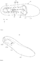
- FIG. 1 is a perspective view of a shoe according to at least one example embodiment
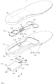
- FIG. 2 is an exploded perspective view of a shoe according to at least one example embodiment
- FIG. 3 is an exploded perspective view of an insole according to at least one example embodiment
- FIG. 4 is a side view of a controller according to at least one example embodiment.
- a shoe 100 may include an insole 1, a midsole 2, an upper 3, and an interface 4.
- the shoe 100 may apply stimuli to a foot of a user or may measure a movement of the foot of the user using an electronic element 12 included in the insole 1.
- the electronic element 12 may include a front electronic element 121 configured to overlap a forefoot of the user based on a direction perpendicular to the insole 1 and a rear electronic element 122 configured to overlap a rearfoot of the user based on the direction perpendicular to the insole 1.
- the direction perpendicular to the insole 1 refers to a direction perpendicular to a top surface of the insole 1, that is, a surface of the insole 1 that contacts a sole of the user, and indicates an approximately z-axial direction based on coordinate axes of FIG. 1 .
- a longitudinal direction of the insole 1 indicates an approximately x-axial direction based on coordinate axes of FIG. 1 .
- a "front portion” indicates a +x-axial direction and a “rear portion” indicates a -x-axial direction in a coordinate system of FIG. 1 .
- the insole 1 includes a surface that contacts the sole of the user and may support the foot of the user.
- the insole 1 may be formed of a flexible material and may give an enhanced comfort when the user wears the shoe 100.
- the insole 1 may be inserted inward into the upper 3 through an upper opening of the upper 3.
- the insole 1 may be provided on an upper sole 32 of the upper 3.
- the insole 1 may be directly provided on a top surface of the midsole 2.
- the insole 1 may be separable from the upper 3.
- the insole 1 may include a base 11, the electronic element 12, a connection line 13, a support layer 14, a controller 15, an insert 16, a cover 19, and coupling members 81 and 82.
- the base 11 and the cover 19 may couple with each other or may be separable from each other.
- the user may clean and/or replace the cover 19 by separating the cover 19 from the base 11.
- All of electronic components, for example, the electronic element 12 and the controller 15, included in the insole 1 may be provided to the base 11, and none of the components may be provided to the cover 19.
- the cover 19 may make a direct contact with the sole of the user and thus, may be relatively easily contaminated compared to the base 11 that does not make a direct contact with the sole of the user.
- the user may maintain the shoe 100 to be in an excellent hygienic state by separating and cleaning only the cover 19.
- the base 11 may be in a shape corresponding to an inner space of the upper 3.
- the base 11 may insert inward into the upper 3 through a portion open in an upper portion of the upper 3.
- the base 11 may include a base body 111, a base protrusion 112, a base hole 113, and a guide 114.
- the base body 111 may support the electronic element 12.
- the front electronic element 121 may be provided in a front portion of the base body 111
- the rear electronic element 122 may be provided in a rear portion of the base body 111.
- the base body 111 may include a base sole 111a configured to support the sole of the user and a base wing 111b configured to protrude upward from a rear edge of the base sole 111a.
- the base wing 11b may surround at least a portion of an edge of the cover 19 that is placed on a top surface of the base body 111 and may inhibit (or, alternatively, prevent) the cover 19 from being pushed rearward in a -x-axial direction or being shaken in a y-axial direction.
- the base protrusion 112 may protrude from the base body 111 and may be inserted into the cover 19.
- the base protrusion 112 may be fitted to the cover 19.
- fit may include a tight fit scheme and a scheme of a mutual geometric coupling method to reduce sliding of the cover 19 relative to the base 11.
- the cover 19 may include a cover groove that is recessed from a bottom surface of the cover 19, and the base protrusion 112 may insert into the cover groove.
- the base protrusion 112 may inhibit (or, alternatively, prevent) the cover 19 from being shaken in a horizontal direction, for example, an x-axial direction or a y-axial direction.
- the base protrusion 112 may surround the electronic element 12.
- the base protrusion 112 may be in a shape that surrounds all of the front electronic element 121 and the rear electronic element 122.
- the base protrusion 112 is in a shape of a closed curve, it is provided as an example only.
- the base protrusion 112 may be in a segmented shape including a plurality of unit bodies.
- the base hole 113 may be formed to pass through the base body 111.
- the base hole 113 may be formed in a direction perpendicular to the insole 1, that is, a z-axial direction.
- the base hole 113 may serve as a path that guides the connection line 13 from the top surface to a bottom surface of the base 11.
- the connection line 13 may pass through the base hole 113 and may be connected to the controller 15.
- the electronic element 12 that interacts with the foot of the user may be provided to be in close contact with the foot of the user and an effect of pressure triggered by the foot of the user against the controller 15 may be reduced, which may lead to enhancing durability of the controller 15.
- the base hole 113 may be formed between the front electronic element 121 and the rear electronic element 122. That is, the base hole 113 may be formed in a portion that overlaps a midfoot portion. According to the above structure, while the user is walking, pressure applied to the base hole 113 and the connection line 13 passing the base hole 113 may relatively decrease, which may lead to reducing a disconnection risk of the connection line 13. For example, during the progress of push-off, strong pressure may be applied to a portion that overlaps a forefoot portion in the insole 1, that is, a portion to which the front electronic element 121 is provided.
- strong pressure may be applied to a portion that overlaps a rearfoot portion in the insole 1, that is, a portion to which the rear electronic element 122 is provided.
- relatively small pressure may be applied to a portion that overlaps a midfoot portion in the insole 1, that is, around the base hole 113.
- the guide 114 may be formed in front of the base hole 113, and may have a slope shape that is inclined rearward and downward of the base body 111.
- the guide 114 may guide the connection line 13 from the top surface to the bottom surface of the base 11 through the base hole 113. Since the guide 114 is in a slope shape that is inclined rearward and downward, the connection line 13 may be bent at a gentle angle.
- the guide 114 may enhance the durability of the connection line 13 by reducing a bending angle of the connection line 13.
- the guide 114 may assist a contact point to be easily secured between the connection line 13 and the controller 15.
- the electronic element 12 may be provided to the base body 111.
- the support layer 14 of a flexible material may be provided to the base body 111, and the electronic element 12 may be provided on a top surface or a bottom surface of the support layer 14 or may be embedded in the support layer 14.
- the electronic element 12 may be directly provided to the base body 111 without using the support layer 14.
- the electronic element 12 may apply stimuli to the foot of the user, may measure the pressure applied from the foot of the user, and/or may sense a motion of the foot of the user.
- the electronic element 12 may include a vibrator, a pressure sensor, a temperature sensor, or an inertial sensor.
- the electronic element 12 may include the vibrator, for example, an eccentric motor.
- the vibrator may cause stochastic resonance on the sole of the user.
- the vibrator may generate vibration noise of a tactile threshold sensible by the sole of the user or less and may provide the vibration noise to the sole of the user.
- a tactile signal transferred to the sole of the user is amplified by resonance with the vibration noise and a sense of the sole of the user may become acute.
- the electronic element 12 may include the pressure sensor, for example, a piezoelectric pressure sensor or a force sensitive resistor (FSR) pressure sensor.
- the pressure sensor may measure a magnitude of pressure applied from the sole of the user. Information measured by the pressure sensor may be used to analyze a gait posture of the user.
- the electronic element 12 may include the temperature sensor.
- the electronic element 12 may measure a temperature of each of the forefoot and the rearfoot of the user.
- the electronic element 12 may include the inertial sensor.
- the inertial sensor may measure a magnitude and/or direction of acceleration of each portion of the foot of the user, for example, the forefoot or the rearfoot of the user. Information measured by the inertial sensor may be used to analyze a gait pattern of the user.
- the electronic element 12 may be provided in plural. Although four electronic elements 12 are illustrated, it is provided as an example. Also, a single electronic element 12 may be configured.
- the electronic elements 12 may include the front electronic element 121 and the rear electronic element 122.
- the front electronic element 121 may include a first front electronic element 121a and a second front electronic element 121b that are arranged in a widthwise direction of the insole 1.
- the first front electronic element 121a may be arranged at a location that overlaps a forefoot portion toward a little toe of the user based on a direction perpendicular to the insole 1, that is, a location that overlaps an outer side portion of the forefoot portion.
- the second front electronic element 121b may be arranged at a location that overlaps a forefoot portion toward a big toe of the user, that is, an inner side portion of the forefoot portion.
- the first front electronic element 121a may apply stimuli to the outer side portion of the forefoot of the user and the second front electronic element 121b may apply stimuli to the inner side portion of the forefoot of the user.
- the first front electronic element 121a and the second front electronic element 121b may measure pressure applied to an outer side and an inner side of the forefoot of the user. The measured pressure information may be used to sense whether the user is currently performing inversion or performing eversion.
- the rear electronic element 122 may include a first rear electronic element 122a and a second rear electronic element 122b that are arranged in a longitudinal direction of the insole 1.
- the first rear electronic element 122a may be provided relatively rearward relative to the second rear electronic element 122b.
- a gait state of the user may be further precisely sensed based on pressure information measured by the first rear electronic element 122a and the second rear electronic element 122b.
- the second rear electronic element 122b may not sense pressure and the first rear electronic element 122a may sense the pressure.
- a magnitude of pressure sensed by the first rear electronic element 122a and a magnitude of pressure sensed by the second rear electronic element 122b may be approximately similar.
- connection line 13 may be electrically connected to the electronic element 12.
- the connection line 13 may extend from the electronic element 12 and may pass through the base 11.
- the connection line 13 may enter the base hole 113 along the guide 114 from the top surface of the base 11.
- An end of the connection line 13 may be connected to the controller 15 that is provided below the base 11.
- One end of the connection line 13 may be connected to the electronic element 12 and another end of the connection line 13 may be connected to the controller 15.
- An access between the electronic element 12 and the controller 15 is enabled through the connection line 13.
- the connection line 13 may be provided on a top surface or a bottom surface of the support layer 14, or may be embedded in the support layer 14.
- the connection line 13 may be directly provided to the base body 111 without using the support layer 14.
- the support layer 14 may support the electronic element 12 and the connection line 13, and may insert inward into the base protrusion 112.
- the support layer 14 may be fitted to the base protrusion 112.
- the support layer 14 may be fastened inside the base protrusion 112 without shaking.
- a sum of thicknesses of the support layer 14 and the electronic element 12 may be identical to a height of the base protrusion 112 that protrudes upward from an inner space of the base protrusion 112 in the base body 111.
- the top surface of the electronic element 12 and the top surface of the base protrusion 112 may be formed at the same height.
- the support layer 14 may include a layer body 141 and a slope part (or, alternatively, a ramp) 142.
- the layer body 141 may be provided on the top surface of the base body 111.
- the layer body 141 may support the electronic element 12 and/or the connection line 13.
- the layer body 141 may be formed of, for example, a flexible film.
- the slope part 142 may be formed in a central portion of the layer body 141 and be bent downward relative to the layer body 141 and thereby provided to the guide 114.
- the slope part 142 may guide the connection line 13 to the controller 15.
- the slope part 142 may be in a slope shape that is inclined downward and rearward from an upper portion of the layer body 141.
- the slope part 142 may be formed by folding and bending a portion of the support layer 14 configured as a single layer and the layer body 141 may be formed using a remaining portion of the support layer 14.
- the controller 15 may be electrically connected to the electronic element 12 and may control the electronic element 12. For example, when the electronic element 12 includes a vibrator, the controller 15 may adjust a frequency and/or an amplitude of the electronic element 12. The controller 15 may receive information from the electronic element 12. For example, when the electronic element 12 includes a pressure sensor or an inertial sensor, the controller 15 may receive information sensed at the electronic element 12.
- the controller 15 may be mounted to the insole 1.
- the controller 15 may insert into an underside of the base 11.
- the midsole 2 does not require a space for receiving the controller 15. That is, the midsole 2 and the upper 3 may be manufactured in a manner similar to a general shoe manufacturing process and may couple with each other regardless of whether the controller 15 is provided. That is, the shoe manufacturing process and a process of manufacturing the base 11 including an electronic part may be separately performed.
- the upper 3 includes the upper sole 32
- the upper sole 32 may be attached on a top surface of the midsole 2.
- the upper 3 may couple with the midsole 2 along the edge of the midsole 2.
- the midsole 2 and the upper 3 do not require a space for receiving the controller 15 and assembly order thereof is not affected by the controller 15. Accordingly, the shoe 100 may be produced on a large scale through a simple automation process without causing damage to various types of electronic parts that are relatively expensive and have low durability or without causing disconnection of the connection line.
- the controller 15 may include a controller body 151, a controller protrusion 152, an access port 153, a power unit 158, and processing circuitry 159. In some example embodiments, the controller 15 may further include a memory (not shown).
- the processing circuitry 159 may include hardware including logic circuits, a hardware/software combination such as a processor executing software; or a combination thereof.
- the processing circuitry may include, but is not limited to, a central processing unit (CPU), an arithmetic logic unit (ALU), a digital signal processor, a microcomputer, a field programmable gate array (FPGA), a System-on-Chip (SoC) a programmable logic unit, a microprocessor, or an application-specific integrated circuit (ASIC), etc.
- CPU central processing unit
- ALU arithmetic logic unit
- FPGA field programmable gate array
- SoC System-on-Chip
- ASIC application-specific integrated circuit
- the processing circuitry 159 may execute instructions stored in the memory to configure the processing circuitry 159 as special purpose processing circuity to control the electronic element 12 in response to a control signal input through the interface 4 or wireless communication.
- the controller body 151 may insert into the base 11 in a first direction.
- the first direction may be a +z-axial direction from an underside of the base 11 toward an upper side of the base 11.
- the controller body 151 may include the power unit 158 and/or the processing circuitry 159.
- the controller body 151 may include controller coupling holes 151a and 151b for coupling with the insert 16.
- the controller coupling holes 151a and 151b may include the first controller coupling hole 151a and the second controller coupling hole 151b that are provided to face each other based on the access port 153.
- the controller protrusion 152 may extend rearward from the controller body 151.
- the controller protrusion 152 may insert into the base 11 in a second direction perpendicular to the first direction.
- the second direction may be a -x-axial direction from forward of the base 11 toward rearward of the base 11. Since the second direction is orthogonal to the first direction, it is possible to inhibit (or, alternatively, prevent) the controller body 151 from being separated downward during a process of mounting the controller body 151 to the base 11.
- the controller protrusion 152 may provide a temporary fastening state by making one end of the controller 15 be locked by the base 11 before mounting the controller body 151.
- a front portion of the controller body 151 couples with the insert 16 and the controller protrusion 152 that extends rearward from the controller body 151 inserts into the base 11. Therefore, a state in which the controller 15 is inserted into the base 11 may be stably maintained while the user is walking. For example, although the central portion of the base 11 is deformed due to a push-off motion of the user, the controller 15 may not be separated from the base 11 since the controller 15 is coupled with the insert 16 of a rigid material. Also, although the rear portion of the base 11 is deformed due to a heel-strike motion of the user, the controller 15 may not be separated from the base 11 since the controller protrusion 152 is inserted into the base 11.
- the access port 153 may be provided on a top surface of the controller body 151.
- the access port 153 may be connected to the connection line 13 that passes through the base hole 113.
- the access port 153 may be a member, for example, a pogo pin, which is elastically deformable in a direction in which the access port 153 is connected to the connection line 13. According to the above, a stable electrical contact point may be provided while the user is walking.
- the power unit 158 may supply power to the electronic element 12.
- the power unit 158 may be charged with power supplied from an outside through the interface 4, or may be wirelessly charged.
- the insert 16 may be provided inside the base 11 and may be formed of a more rigid material than that of the base 11.
- the insert 16 may be integrally formed with the base 11 inside the base 11 by forming the base 11 through a resin foaming process in a state in which the insert 16 is provided in a molding frame for forming the base 11.
- the insert 16 may be present adjacent to the base hole 113 and may overlap the controller 15 based on the direction perpendicular to the insole 1.
- the insert 16 may include insert coupling holes 16a and 16b for coupling with the controller 15.
- the insert coupling hole 16a, 16b may include a screw thread inward.
- the insert coupling holes 16a and 16b may include the first insert coupling hole 16a corresponding to the first controller coupling hole 151a and the second insert coupling hole 16b corresponding to the second controller coupling hole 151b.
- FIG. 3 illustrates an example embodiment of fastening a front end of the controller 15 using a single insert 16, it is provided as an example only. A plurality of inserts 16 may be provided and used to fasten another portion of the controller 15. Also, the insert 16 may be in a different shape to make it possible to fasten a plurality of portions of the controller 15.
- the cover 19 may be provided on the top surface of the base 11 to cover the electronic element 12 such that the electronic element 12 does not make a direct contact with the foot of the user.
- the shape of the cover 19 may be approximately similar to the shape of the base 11.
- the cover 19 may mostly overlap the base 11 based on the direction perpendicular to the insole 1.
- the cover 19 may be in a shape of a cover sole 19a and a cover wing 19b, where the cover wing 19b is configured to protrude upward from a rear edge portion of the cover sole 19a.
- the cover wing 19b may stably support the rearfoot of the user by surrounding a rear portion and a side portion of the rearfoot of the user.
- an electronic part may not be provided in the cover 19.
- the user may clean or replace the cover 19 by separating only the cover 19 from the shoe 100. Also, without a need to modify a structure of the base 11 that includes various types of electronic parts, it is possible to provide the cover 19 in a shape that is customized for various shapes of the foot of the user. Accordingly, it is possible to save the overall cost and efforts for manufacturing the shoe 100.
- the coupling members 81 and 82 may be used to couple the controller 15 and the insert 16.
- the coupling members 81 and 82 may be bolts that are screwable to the controller 15 and the insert 16.
- the midsole 2 may form at least a portion of a lower external appearance of the shoe 100.
- the midsole 2 becomes thicker with getting closer to a rear portion. Therefore, a front portion of the midsole 2 configured to support the forefoot of the user may have a thickness less than that of a portion configured to support a heel of the user.
- the midsole 2 may include a midsole body 21 and a plurality of midsole grooves 22. If necessary, the midsole 2 may include an outsole (not shown) formed on a bottom surface of the midsole body 21 and formed of a more rigid material than that of the midsole body 21.
- the midsole body 21 may support the insole 1.
- the upper 3 may be provided above the midsole body 21.
- the midsole body 21 may be formed of, for example, phylon, cushion, ethylene-vinyl acetate copolymer (EVA), or solyte.
- a plurality of midsole grooves 22 may be formed in a direction, for example, a y-axial direction, which intersects a longitudinal (x-axial direction) of the midsole body 21 and may be provided at a location at which the midsole grooves 22 do not overlap the electronic element 12.
- the midsole groove 22 may be provided in front of the electronic element 12.
- the plurality of midsole grooves 22 may guide a location at which the midsole body 21 bends.
- the plurality of midsole grooves 22 may assist the midsole body 21 to bend at a nonoverlapping location with the electronic element 12, thereby reducing a risk that the electronic element 12 may be damaged.
- the midsole groove 22 may be recessed from the top surface of the midsole body 21.
- the plurality of midsole grooves 22 may be formed in parallel.
- the midsole 2 may include a plurality of midsole grooves 22 therein.
- example embodiments are not limited thereto.
- the insole 1 may include grooves in one or more of the insole body 11 and/or the cover 19 to urge he insole 1 to flex at a location that does not correspond to the electronic element 12.
- the upper 3 may form an upper external appearance of the shoe 100 and may wrap around the foot of the user.
- the upper 3 may include an upper body 31 and an upper sole 32 configured to contact the top surface of the midsole body 21.
- the upper body 31 may include an upper hole 31a through which the interface 4 accesses the controller 15.
- the interface 4 may be connected to the controller 15 by passing through the upper hole 31a.
- the upper hole 31a may be formed on a rear surface of the upper body 31.
- the interface 4 may be electrically connected to the controller 15.
- a portion of the interface 4 may be provided at the rear of the midsole 2 and externally exposed and a remaining portion of the interface 4 may be connected to the controller 15.
- the interface 4 may include an input unit, for example, a button, configured to receive a control signal from the user and may transmit the control signal to the processing circuitry 159.
- the interface 4 may be supplied with power from an outside and may supply the power to the power unit 158.
- FIG. 5 is a top view of a cover according to at least one example embodiment
- FIG. 6 is a bottom view of a cover according to at least one example embodiment
- FIG. 7 is a cross-sectional view of a cover according to at least one example embodiment
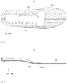
- FIG. 8 is a top view illustrating a base, an electronic element, a connection line, and a support layer according to at least one example embodiment
- FIG. 9 is a perspective view of a base according to at least one example embodiment
- FIG. 10 is a perspective view of the base of FIG. 9 observed at a different angle.
- the cover 19 may be separable from the base 11.
- the cover 19 may have a shape that includes the cover sole 19a and the cover wing 19b.
- the cover 19 may include a cover body 191 including a cover groove 191a and a cover protrusion 192 configured to protrude from the cover body 191.
- the cover groove 191a may be in a shape that receives the electronic element 12 and the support layer 14.
- the front electronic element 121 may be received in a front portion of the cover groove 191a and the rear electronic element 122 may be received in a rear portion of the cover groove 191a.
- the front portion of the cover groove 191a may be relatively wider than the rear portion of the cover groove 191a.
- a depth of the cover groove 191a that is recessed from a bottom surface of the cover body 191 may be approximately identical to a sum of thicknesses of the support layer 14 and the electronic element 12.
- the base protrusion 112 may be fitted to the cover groove 191a.
- the cover groove 191a may be in a shape corresponding to a shape of the base protrusion 112.
- example embodiments are not limited to the cover 19 being connected to the base 11 via only the protrusion 112 connected to the groove 191a.
- the cover 19 may be connected to the base 11 by various fastening means.
- the cover 19 and the base body 111 be connected via a hook-and-loop fastener.
- the hook-and-loop fastener may be used in addition to the protrusion 112 and the groove 191a to provide additional fixing force between the cover 19 and the base 11.
- the hook-and-loop fastener may be used in lieu of the protrusion 112 and the groove 191a to fix the cover 19 to the base 11.
- the cover protrusion 192 may press the support layer 14.
- the cover protrusion 192 may press a portion that does not support the electronic element 12 in the support layer 14.
- the cover protrusion 192 may protrude from the cover body 191 by a length corresponding to a thickness of the electronic element 12.
- the support layer 14 may be in contact with the cover protrusion 192.
- the cover protrusion 192 may assist a central portion of the support layer 14 to not shake vertically.
- the support layer 14 may be fitted inside the base protrusion 112.
- an edge portion of the layer body 141 may maintain a contact state with an inner wall of the base protrusion 112.
- a horizontal shaking of the front electronic element 121 and the rear electronic element 122 may be limited.
- the support layer 14 may be separated from the base 11 and may be repaired and/or replaced.
- various types of support layers 14 may support various types of electronic elements 12.
- the support layer 14 may support one of an electronic element including an eccentric motor, an electronic element including a pressure sensor, and an electronic element including an inertial sensor. The user may selectively provide the support layer 14 supporting a desired electronic element to the base 11.
- the base body 111 may include a base main groove 111c recessed from a bottom surface of the base body 111, a base auxiliary groove 111d that is recessed from one side surface of the base main groove 111c toward the rear portion of the base 11, and a line receiving groove 111e.
- the base main groove 111c may receive the controller body 151 of FIG. 3
- the base auxiliary groove 111d may receive the controller protrusion 152 of FIG. 3 .
- the user may insert the controller protrusion 152 into the base auxiliary groove 111d with titling the controller body 151 and may lift the controller body 151 to be fully inserted into the base main groove 111c.
- the line receiving groove 111e may receive a power line 44a of FIG. 13 .
- the line receiving groove 111e may inhibit (or, alternatively, prevent) aging of the power line 44a by friction with the insole 1 during a walking process of the user and may also enable a stable connection between the controller 15 and the interface 4.
- the line receiving groove 111e may be formed across the rear surface and the bottom surface of the base body 111.
- the line receiving groove 111e may be in a shape that communicates with the base main groove 111c.
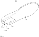
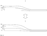
- FIG. 11 is a side view illustrating an example of replacing a cover according to at least one example embodiment.
- the cover 19 may be replaced while the electronic element 12 remains mounted to the base 11.
- the user may use the cover 19 that is customized for the user in various ways such as, for example, height, rigidity and/or shape.
- the user may replace the cover 19 with a height h1 with a cover 19' with a height h2 with respect to a portion that supports the rearfoot of the user.
- FIG. 12 is a cross-sectional view of an insole according to at least one example embodiment
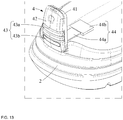
- FIG. 13 is a perspective view illustrating a midsole and an interface according to at least one example embodiment
- FIG. 14 is a perspective view illustrating a state in which an interface cover is separated from an interface body according to at least one example embodiment.
- the interface 4 may include an interface body 41, an interface cover 42, a connecting portion 43, and a connector 44.
- the interface body 41 may be fastened to the midsole 2.
- the interface body 41 may be fastened to a rear edge portion of the midsole 2.
- the interface body 41 may be formed of a more rigid material than that of the upper 3 of FIG. 1 and may act as a back counter of the shoe 100.
- the interface body 41 may include a body magnet 411 configured to apply a magnetic force to the interface cover 42.
- a plurality of body magnets 411 may be provided.
- the interface cover 42 may be detachably provided to the interface body 41.
- the interface cover 42 may include a cover magnet 421 configured to face the body magnet 411 with a polarity opposite to that of the body magnet 411 and a power terminal 422 configured to receive power that is supplied to the power unit 158 of FIG. 4 .
- a plurality of cover magnets 421 may be provided.
- An external charging device C may be connected to the power terminal 422.
- An upper end 43a of the connecting portion 43 may be connected to the interface cover 42 and a lower end 43b of the connecting portion 43 may be fastened to the interface body 41.
- the connecting portion 43 may assist the interface cover 42 not to be separated from the shoe 100. The user may separate the interface cover 42 from the interface body 41 by pulling an upper end of the interface cover 42.
- the connecting portion 43 may be formed of an elastic material.
- the connector 44 may pass through the upper hole 31a of the upper 3 of FIG. 2 and may connect the power terminal 422 and the controller 15 of FIG. 3 .
- the connector 44 may include the power line 44a configured to pass through the upper 3 and a connector terminal 44b provided at an end of the power line 44a and configured to connect to the controller 15.
- the power line 44a may extend along the rear surface and the bottom surface of the base 11.
- the power line 44a may include a flexible material, such as a fabric material.
- the power line 44a may tolerate the clearance, thereby reducing a risk of disconnection. That is, it is possible to enhance the product durability compared to a case in which the connector 44 is in an overall rigid structure.
- the connector terminal 44b may be provided to be detachable from a bottom surface of the controller 15. According to the above structure, if there is a need to repair or replace electronic parts installed on the base 11, the entire base 11 may be easily separated from the shoe 100 by separating the connector terminal 44b from the controller 15.
- connection line 13 may be guided to the underside of the base 11 by the slope part 142.
- the coupling members 81 and 82 couple the controller body 151 and the insert 16
- the access port 153 may be in contact with the connection line 13.
- the controller body 151 may include an elastic body (not shown) configured to provide an upward elastic force to the access port 153.
Landscapes
- Health & Medical Sciences (AREA)
- Life Sciences & Earth Sciences (AREA)
- Engineering & Computer Science (AREA)
- Physics & Mathematics (AREA)
- Microelectronics & Electronic Packaging (AREA)
- General Physics & Mathematics (AREA)
- Animal Behavior & Ethology (AREA)
- Veterinary Medicine (AREA)
- Heart & Thoracic Surgery (AREA)
- Medical Informatics (AREA)
- Molecular Biology (AREA)
- Surgery (AREA)
- Pathology (AREA)
- General Health & Medical Sciences (AREA)
- Public Health (AREA)
- Biomedical Technology (AREA)
- Biophysics (AREA)
- Dentistry (AREA)
- Oral & Maxillofacial Surgery (AREA)
- Chemical & Material Sciences (AREA)
- Physiology (AREA)
- Materials Engineering (AREA)
- Analytical Chemistry (AREA)
- Footwear And Its Accessory, Manufacturing Method And Apparatuses (AREA)
Applications Claiming Priority (1)
| Application Number | Priority Date | Filing Date | Title |
|---|---|---|---|
| KR1020190025343A KR102589950B1 (ko) | 2019-03-05 | 2019-03-05 | 인솔 및 이를 포함하는 신발 |
Publications (2)
| Publication Number | Publication Date |
|---|---|
| EP3704986A1 true EP3704986A1 (de) | 2020-09-09 |
| EP3704986B1 EP3704986B1 (de) | 2021-08-11 |
Family
ID=68848102
Family Applications (1)
| Application Number | Title | Priority Date | Filing Date |
|---|---|---|---|
| EP19214921.9A Active EP3704986B1 (de) | 2019-03-05 | 2019-12-10 | Einlegesohle und schuhe damit |
Country Status (4)
| Country | Link |
|---|---|
| US (1) | US11464274B2 (de) |
| EP (1) | EP3704986B1 (de) |
| KR (1) | KR102589950B1 (de) |
| CN (1) | CN111657620B (de) |
Cited By (2)
| Publication number | Priority date | Publication date | Assignee | Title |
|---|---|---|---|---|
| GB2617388A (en) * | 2022-04-08 | 2023-10-11 | Walk With Path Ltd | Footwear article |
| KR20240135216A (ko) * | 2023-03-03 | 2024-09-10 | 주식회사 오투랩 | 스마트 인솔 |
Families Citing this family (3)
| Publication number | Priority date | Publication date | Assignee | Title |
|---|---|---|---|---|
| WO2020195373A1 (ja) * | 2019-03-27 | 2020-10-01 | 日本電気株式会社 | 中敷き型電子機器および中敷き型電子機器の製造方法 |
| KR102831073B1 (ko) * | 2022-08-29 | 2025-07-07 | 솔티드 주식회사 | 무선 충전이 가능한 인솔 및 이를 포함하는 무선 충전 시스템 |
| USD1032158S1 (en) * | 2023-05-15 | 2024-06-25 | Skechers U.S.A., Inc. Ii | Shoe midsole periphery |
Citations (7)
| Publication number | Priority date | Publication date | Assignee | Title |
|---|---|---|---|---|
| US6195921B1 (en) * | 1999-09-28 | 2001-03-06 | Vinncente Hoa Gia Truong | Virtual intelligence shoe with a podiatric analysis system |
| US20110107771A1 (en) * | 2009-11-05 | 2011-05-12 | Columbia Sportswear North America, Inc. | Footwear temperature control method and apparatus |
| EP2675355A2 (de) * | 2011-02-17 | 2013-12-25 | Nike International Ltd. | Schuhwerk mit sensorsystem |
| EP3153046A1 (de) * | 2011-02-17 | 2017-04-12 | NIKE Innovate C.V. | Schuhwerkeinsatz mit sensorsystem |
| US20180042338A1 (en) * | 2016-08-11 | 2018-02-15 | Nike, Inc. | Sole structure for an article of footwear having a nonlinear bending stiffness |
| US20180055140A1 (en) * | 2016-08-26 | 2018-03-01 | Aria S.R.L. | Insole for controlling and adjusting the temperature of the foot |
| US20180085030A1 (en) * | 2016-09-27 | 2018-03-29 | stAPPtronics GmH | Insole or shoe sole |
Family Cites Families (22)
| Publication number | Priority date | Publication date | Assignee | Title |
|---|---|---|---|---|
| US5846063A (en) * | 1987-05-26 | 1998-12-08 | Nikola Lakic | Miniature universal pump and valve for inflatable liners |
| US5592759A (en) * | 1995-01-26 | 1997-01-14 | Co-Jo Sports, Inc. | Vibrating footwear |
| US20020133973A1 (en) * | 2001-03-23 | 2002-09-26 | Ku-Shen Lin | Heat sole |
| AU2004220619A1 (en) | 2003-03-06 | 2004-09-23 | Afferent Corporation | Method and apparatus for improving human balance and gait and preventing foot injury |
| GB2405571B (en) * | 2003-09-02 | 2006-10-25 | Tariq Mirza | A shoe and accessories therefor |
| US8205356B2 (en) * | 2004-11-22 | 2012-06-26 | Frampton E. Ellis | Devices with internal flexibility sipes, including siped chambers for footwear |
| US8398570B2 (en) | 2006-04-14 | 2013-03-19 | Engineering Acoustics, Inc. | Wide band vibrational stimulus device |
| US7347831B2 (en) * | 2006-07-10 | 2008-03-25 | Hsao-Hsing Chiu | Shoe with massaging and warming arrangements |
| US7997007B2 (en) * | 2006-09-15 | 2011-08-16 | Early Success, Inc. | Stimulus training system and apparatus to effectuate therapeutic treatment |
| KR100795830B1 (ko) | 2006-11-01 | 2008-01-17 | 주식회사 지맨 | 기능성 신발 |
| US7913428B2 (en) * | 2007-07-20 | 2011-03-29 | Ching-Hung Wang | Electromagnetic fitness shoes with a conductor structure |
| US8384551B2 (en) * | 2008-05-28 | 2013-02-26 | MedHab, LLC | Sensor device and method for monitoring physical stresses placed on a user |
| US20110251520A1 (en) | 2010-04-08 | 2011-10-13 | Yuan Ze University | Fall-risk Evaluation and Balance Stability Enhancement System and method |
| JP4988942B1 (ja) | 2011-05-20 | 2012-08-01 | 英治 川西 | リニアシューズ |
| KR101115495B1 (ko) | 2011-08-24 | 2012-03-05 | 김미영 | 유연성 통전전극부가 포함되는 전기자극수단이 구비된 신발 |
| CN106963022B (zh) * | 2012-02-22 | 2019-12-31 | 耐克创新有限合伙公司 | 具有传感器系统的鞋类 |
| US10369075B2 (en) * | 2015-03-03 | 2019-08-06 | Avex, Llc | Insole foot compression system and methods |
| US10617597B2 (en) | 2015-10-22 | 2020-04-14 | President And Fellows Of Harvard College | Insole design and actuator placement for balance and gait |
| CN105533905A (zh) * | 2016-03-04 | 2016-05-04 | 林镕 | 一种稳定快速自充电智能健康跑步鞋 |
| KR101878254B1 (ko) | 2016-10-31 | 2018-07-13 | 부산외국어대학교 산학협력단 | 컴퓨터를 포함하는 스마트 신발 시스템 및 이의 구현방법 |
| CN207784459U (zh) * | 2017-12-29 | 2018-08-31 | 重庆小爱科技有限公司 | 一种智能发热鞋垫 |
| KR102514651B1 (ko) | 2018-08-27 | 2023-03-28 | 삼성전자주식회사 | 인솔 및 이를 포함하는 신발 |
-
2019
- 2019-03-05 KR KR1020190025343A patent/KR102589950B1/ko active Active
- 2019-08-23 CN CN201910783445.4A patent/CN111657620B/zh active Active
- 2019-10-23 US US16/661,338 patent/US11464274B2/en active Active
- 2019-12-10 EP EP19214921.9A patent/EP3704986B1/de active Active
Patent Citations (7)
| Publication number | Priority date | Publication date | Assignee | Title |
|---|---|---|---|---|
| US6195921B1 (en) * | 1999-09-28 | 2001-03-06 | Vinncente Hoa Gia Truong | Virtual intelligence shoe with a podiatric analysis system |
| US20110107771A1 (en) * | 2009-11-05 | 2011-05-12 | Columbia Sportswear North America, Inc. | Footwear temperature control method and apparatus |
| EP2675355A2 (de) * | 2011-02-17 | 2013-12-25 | Nike International Ltd. | Schuhwerk mit sensorsystem |
| EP3153046A1 (de) * | 2011-02-17 | 2017-04-12 | NIKE Innovate C.V. | Schuhwerkeinsatz mit sensorsystem |
| US20180042338A1 (en) * | 2016-08-11 | 2018-02-15 | Nike, Inc. | Sole structure for an article of footwear having a nonlinear bending stiffness |
| US20180055140A1 (en) * | 2016-08-26 | 2018-03-01 | Aria S.R.L. | Insole for controlling and adjusting the temperature of the foot |
| US20180085030A1 (en) * | 2016-09-27 | 2018-03-29 | stAPPtronics GmH | Insole or shoe sole |
Cited By (2)
| Publication number | Priority date | Publication date | Assignee | Title |
|---|---|---|---|---|
| GB2617388A (en) * | 2022-04-08 | 2023-10-11 | Walk With Path Ltd | Footwear article |
| KR20240135216A (ko) * | 2023-03-03 | 2024-09-10 | 주식회사 오투랩 | 스마트 인솔 |
Also Published As
| Publication number | Publication date |
|---|---|
| CN111657620B (zh) | 2024-09-03 |
| EP3704986B1 (de) | 2021-08-11 |
| CN111657620A (zh) | 2020-09-15 |
| KR102589950B1 (ko) | 2023-10-16 |
| US20200281303A1 (en) | 2020-09-10 |
| US11464274B2 (en) | 2022-10-11 |
| KR20200106746A (ko) | 2020-09-15 |
Similar Documents
| Publication | Publication Date | Title |
|---|---|---|
| EP3704986B1 (de) | Einlegesohle und schuhe damit | |
| JP7444559B2 (ja) | 靴 | |
| US11234478B2 (en) | Insole and shoes comprising the same | |
| EP2226006B1 (de) | Detektor für position oder gravitationszentrum und tragbarer bewegungsassistent mit dem detektor für position oder gravitationszentrum | |
| US11472143B2 (en) | Method of manufacturing insole | |
| US11647806B2 (en) | Smart insole and balance enhancement device comprising the same | |
| CN113017187B (zh) | 鞋型装置及其控制方法 | |
| JP7522166B2 (ja) | センサ装置、履物、及び履物セット |
Legal Events
| Date | Code | Title | Description |
|---|---|---|---|
| PUAI | Public reference made under article 153(3) epc to a published international application that has entered the european phase |
Free format text: ORIGINAL CODE: 0009012 |
|
| STAA | Information on the status of an ep patent application or granted ep patent |
Free format text: STATUS: THE APPLICATION HAS BEEN PUBLISHED |
|
| AK | Designated contracting states |
Kind code of ref document: A1 Designated state(s): AL AT BE BG CH CY CZ DE DK EE ES FI FR GB GR HR HU IE IS IT LI LT LU LV MC MK MT NL NO PL PT RO RS SE SI SK SM TR |
|
| AX | Request for extension of the european patent |
Extension state: BA ME |
|
| STAA | Information on the status of an ep patent application or granted ep patent |
Free format text: STATUS: REQUEST FOR EXAMINATION WAS MADE |
|
| 17P | Request for examination filed |
Effective date: 20201028 |
|
| RBV | Designated contracting states (corrected) |
Designated state(s): AL AT BE BG CH CY CZ DE DK EE ES FI FR GB GR HR HU IE IS IT LI LT LU LV MC MK MT NL NO PL PT RO RS SE SI SK SM TR |
|
| RIN1 | Information on inventor provided before grant (corrected) |
Inventor name: SHIM, YOUNG BO Inventor name: BAE, YEJI Inventor name: ROH, CHANG HYUN Inventor name: AHN, HAEWOOK Inventor name: ROH, SE-GON Inventor name: CHOI, MINHO |
|
| GRAP | Despatch of communication of intention to grant a patent |
Free format text: ORIGINAL CODE: EPIDOSNIGR1 |
|
| STAA | Information on the status of an ep patent application or granted ep patent |
Free format text: STATUS: GRANT OF PATENT IS INTENDED |
|
| INTG | Intention to grant announced |
Effective date: 20210310 |
|
| GRAS | Grant fee paid |
Free format text: ORIGINAL CODE: EPIDOSNIGR3 |
|
| GRAA | (expected) grant |
Free format text: ORIGINAL CODE: 0009210 |
|
| STAA | Information on the status of an ep patent application or granted ep patent |
Free format text: STATUS: THE PATENT HAS BEEN GRANTED |
|
| AK | Designated contracting states |
Kind code of ref document: B1 Designated state(s): AL AT BE BG CH CY CZ DE DK EE ES FI FR GB GR HR HU IE IS IT LI LT LU LV MC MK MT NL NO PL PT RO RS SE SI SK SM TR |
|
| REG | Reference to a national code |
Ref country code: CH Ref legal event code: EP |
|
| REG | Reference to a national code |
Ref country code: DE Ref legal event code: R096 Ref document number: 602019006807 Country of ref document: DE |
|
| REG | Reference to a national code |
Ref country code: IE Ref legal event code: FG4D Ref country code: AT Ref legal event code: REF Ref document number: 1418467 Country of ref document: AT Kind code of ref document: T Effective date: 20210915 |
|
| REG | Reference to a national code |
Ref country code: LT Ref legal event code: MG9D |
|
| REG | Reference to a national code |
Ref country code: NL Ref legal event code: MP Effective date: 20210811 |
|
| REG | Reference to a national code |
Ref country code: AT Ref legal event code: MK05 Ref document number: 1418467 Country of ref document: AT Kind code of ref document: T Effective date: 20210811 |
|
| PG25 | Lapsed in a contracting state [announced via postgrant information from national office to epo] |
Ref country code: RS Free format text: LAPSE BECAUSE OF FAILURE TO SUBMIT A TRANSLATION OF THE DESCRIPTION OR TO PAY THE FEE WITHIN THE PRESCRIBED TIME-LIMIT Effective date: 20210811 Ref country code: SE Free format text: LAPSE BECAUSE OF FAILURE TO SUBMIT A TRANSLATION OF THE DESCRIPTION OR TO PAY THE FEE WITHIN THE PRESCRIBED TIME-LIMIT Effective date: 20210811 Ref country code: ES Free format text: LAPSE BECAUSE OF FAILURE TO SUBMIT A TRANSLATION OF THE DESCRIPTION OR TO PAY THE FEE WITHIN THE PRESCRIBED TIME-LIMIT Effective date: 20210811 Ref country code: BG Free format text: LAPSE BECAUSE OF FAILURE TO SUBMIT A TRANSLATION OF THE DESCRIPTION OR TO PAY THE FEE WITHIN THE PRESCRIBED TIME-LIMIT Effective date: 20211111 Ref country code: AT Free format text: LAPSE BECAUSE OF FAILURE TO SUBMIT A TRANSLATION OF THE DESCRIPTION OR TO PAY THE FEE WITHIN THE PRESCRIBED TIME-LIMIT Effective date: 20210811 Ref country code: LT Free format text: LAPSE BECAUSE OF FAILURE TO SUBMIT A TRANSLATION OF THE DESCRIPTION OR TO PAY THE FEE WITHIN THE PRESCRIBED TIME-LIMIT Effective date: 20210811 Ref country code: FI Free format text: LAPSE BECAUSE OF FAILURE TO SUBMIT A TRANSLATION OF THE DESCRIPTION OR TO PAY THE FEE WITHIN THE PRESCRIBED TIME-LIMIT Effective date: 20210811 Ref country code: HR Free format text: LAPSE BECAUSE OF FAILURE TO SUBMIT A TRANSLATION OF THE DESCRIPTION OR TO PAY THE FEE WITHIN THE PRESCRIBED TIME-LIMIT Effective date: 20210811 Ref country code: PT Free format text: LAPSE BECAUSE OF FAILURE TO SUBMIT A TRANSLATION OF THE DESCRIPTION OR TO PAY THE FEE WITHIN THE PRESCRIBED TIME-LIMIT Effective date: 20211213 Ref country code: NO Free format text: LAPSE BECAUSE OF FAILURE TO SUBMIT A TRANSLATION OF THE DESCRIPTION OR TO PAY THE FEE WITHIN THE PRESCRIBED TIME-LIMIT Effective date: 20211111 |
|
| PG25 | Lapsed in a contracting state [announced via postgrant information from national office to epo] |
Ref country code: PL Free format text: LAPSE BECAUSE OF FAILURE TO SUBMIT A TRANSLATION OF THE DESCRIPTION OR TO PAY THE FEE WITHIN THE PRESCRIBED TIME-LIMIT Effective date: 20210811 Ref country code: LV Free format text: LAPSE BECAUSE OF FAILURE TO SUBMIT A TRANSLATION OF THE DESCRIPTION OR TO PAY THE FEE WITHIN THE PRESCRIBED TIME-LIMIT Effective date: 20210811 Ref country code: GR Free format text: LAPSE BECAUSE OF FAILURE TO SUBMIT A TRANSLATION OF THE DESCRIPTION OR TO PAY THE FEE WITHIN THE PRESCRIBED TIME-LIMIT Effective date: 20211112 |
|
| PG25 | Lapsed in a contracting state [announced via postgrant information from national office to epo] |
Ref country code: NL Free format text: LAPSE BECAUSE OF FAILURE TO SUBMIT A TRANSLATION OF THE DESCRIPTION OR TO PAY THE FEE WITHIN THE PRESCRIBED TIME-LIMIT Effective date: 20210811 |
|
| PG25 | Lapsed in a contracting state [announced via postgrant information from national office to epo] |
Ref country code: DK Free format text: LAPSE BECAUSE OF FAILURE TO SUBMIT A TRANSLATION OF THE DESCRIPTION OR TO PAY THE FEE WITHIN THE PRESCRIBED TIME-LIMIT Effective date: 20210811 |
|
| REG | Reference to a national code |
Ref country code: DE Ref legal event code: R097 Ref document number: 602019006807 Country of ref document: DE |
|
| PG25 | Lapsed in a contracting state [announced via postgrant information from national office to epo] |
Ref country code: SM Free format text: LAPSE BECAUSE OF FAILURE TO SUBMIT A TRANSLATION OF THE DESCRIPTION OR TO PAY THE FEE WITHIN THE PRESCRIBED TIME-LIMIT Effective date: 20210811 Ref country code: SK Free format text: LAPSE BECAUSE OF FAILURE TO SUBMIT A TRANSLATION OF THE DESCRIPTION OR TO PAY THE FEE WITHIN THE PRESCRIBED TIME-LIMIT Effective date: 20210811 Ref country code: RO Free format text: LAPSE BECAUSE OF FAILURE TO SUBMIT A TRANSLATION OF THE DESCRIPTION OR TO PAY THE FEE WITHIN THE PRESCRIBED TIME-LIMIT Effective date: 20210811 Ref country code: EE Free format text: LAPSE BECAUSE OF FAILURE TO SUBMIT A TRANSLATION OF THE DESCRIPTION OR TO PAY THE FEE WITHIN THE PRESCRIBED TIME-LIMIT Effective date: 20210811 Ref country code: CZ Free format text: LAPSE BECAUSE OF FAILURE TO SUBMIT A TRANSLATION OF THE DESCRIPTION OR TO PAY THE FEE WITHIN THE PRESCRIBED TIME-LIMIT Effective date: 20210811 Ref country code: AL Free format text: LAPSE BECAUSE OF FAILURE TO SUBMIT A TRANSLATION OF THE DESCRIPTION OR TO PAY THE FEE WITHIN THE PRESCRIBED TIME-LIMIT Effective date: 20210811 |
|
| PLBE | No opposition filed within time limit |
Free format text: ORIGINAL CODE: 0009261 |
|
| STAA | Information on the status of an ep patent application or granted ep patent |
Free format text: STATUS: NO OPPOSITION FILED WITHIN TIME LIMIT |
|
| 26N | No opposition filed |
Effective date: 20220512 |
|
| PG25 | Lapsed in a contracting state [announced via postgrant information from national office to epo] |
Ref country code: MC Free format text: LAPSE BECAUSE OF FAILURE TO SUBMIT A TRANSLATION OF THE DESCRIPTION OR TO PAY THE FEE WITHIN THE PRESCRIBED TIME-LIMIT Effective date: 20210811 Ref country code: IT Free format text: LAPSE BECAUSE OF FAILURE TO SUBMIT A TRANSLATION OF THE DESCRIPTION OR TO PAY THE FEE WITHIN THE PRESCRIBED TIME-LIMIT Effective date: 20210811 |
|
| PG25 | Lapsed in a contracting state [announced via postgrant information from national office to epo] |
Ref country code: SI Free format text: LAPSE BECAUSE OF FAILURE TO SUBMIT A TRANSLATION OF THE DESCRIPTION OR TO PAY THE FEE WITHIN THE PRESCRIBED TIME-LIMIT Effective date: 20210811 |
|
| REG | Reference to a national code |
Ref country code: BE Ref legal event code: MM Effective date: 20211231 |
|
| PG25 | Lapsed in a contracting state [announced via postgrant information from national office to epo] |
Ref country code: LU Free format text: LAPSE BECAUSE OF NON-PAYMENT OF DUE FEES Effective date: 20211210 Ref country code: IE Free format text: LAPSE BECAUSE OF NON-PAYMENT OF DUE FEES Effective date: 20211210 |
|
| PG25 | Lapsed in a contracting state [announced via postgrant information from national office to epo] |
Ref country code: FR Free format text: LAPSE BECAUSE OF NON-PAYMENT OF DUE FEES Effective date: 20211231 Ref country code: BE Free format text: LAPSE BECAUSE OF NON-PAYMENT OF DUE FEES Effective date: 20211231 |
|
| PG25 | Lapsed in a contracting state [announced via postgrant information from national office to epo] |
Ref country code: CY Free format text: LAPSE BECAUSE OF FAILURE TO SUBMIT A TRANSLATION OF THE DESCRIPTION OR TO PAY THE FEE WITHIN THE PRESCRIBED TIME-LIMIT Effective date: 20210811 |
|
| PG25 | Lapsed in a contracting state [announced via postgrant information from national office to epo] |
Ref country code: HU Free format text: LAPSE BECAUSE OF FAILURE TO SUBMIT A TRANSLATION OF THE DESCRIPTION OR TO PAY THE FEE WITHIN THE PRESCRIBED TIME-LIMIT; INVALID AB INITIO Effective date: 20191210 |
|
| REG | Reference to a national code |
Ref country code: CH Ref legal event code: PL |
|
| PG25 | Lapsed in a contracting state [announced via postgrant information from national office to epo] |
Ref country code: LI Free format text: LAPSE BECAUSE OF NON-PAYMENT OF DUE FEES Effective date: 20221231 Ref country code: CH Free format text: LAPSE BECAUSE OF NON-PAYMENT OF DUE FEES Effective date: 20221231 |
|
| PG25 | Lapsed in a contracting state [announced via postgrant information from national office to epo] |
Ref country code: MK Free format text: LAPSE BECAUSE OF FAILURE TO SUBMIT A TRANSLATION OF THE DESCRIPTION OR TO PAY THE FEE WITHIN THE PRESCRIBED TIME-LIMIT Effective date: 20210811 |
|
| PG25 | Lapsed in a contracting state [announced via postgrant information from national office to epo] |
Ref country code: MT Free format text: LAPSE BECAUSE OF FAILURE TO SUBMIT A TRANSLATION OF THE DESCRIPTION OR TO PAY THE FEE WITHIN THE PRESCRIBED TIME-LIMIT Effective date: 20210811 |
|
| PG25 | Lapsed in a contracting state [announced via postgrant information from national office to epo] |
Ref country code: TR Free format text: LAPSE BECAUSE OF FAILURE TO SUBMIT A TRANSLATION OF THE DESCRIPTION OR TO PAY THE FEE WITHIN THE PRESCRIBED TIME-LIMIT Effective date: 20210811 |
|
| PGFP | Annual fee paid to national office [announced via postgrant information from national office to epo] |
Ref country code: DE Payment date: 20251120 Year of fee payment: 7 |
|
| PGFP | Annual fee paid to national office [announced via postgrant information from national office to epo] |
Ref country code: GB Payment date: 20251120 Year of fee payment: 7 |