EP3704922A1 - Coulter assembly and distribution machine with same assembly - Google Patents
Coulter assembly and distribution machine with same assembly Download PDFInfo
- Publication number
- EP3704922A1 EP3704922A1 EP20401005.2A EP20401005A EP3704922A1 EP 3704922 A1 EP3704922 A1 EP 3704922A1 EP 20401005 A EP20401005 A EP 20401005A EP 3704922 A1 EP3704922 A1 EP 3704922A1
- Authority
- EP
- European Patent Office
- Prior art keywords
- coulter
- support arm
- disc
- arrangement
- furrow former
- Prior art date
- Legal status (The legal status is an assumption and is not a legal conclusion. Google has not performed a legal analysis and makes no representation as to the accuracy of the status listed.)
- Pending
Links
- 239000003337 fertilizer Substances 0.000 claims abstract description 16
- 230000000149 penetrating effect Effects 0.000 claims abstract 2
- 238000005553 drilling Methods 0.000 claims description 25
- 230000036316 preload Effects 0.000 claims description 3
- 239000002689 soil Substances 0.000 description 7
- 239000000463 material Substances 0.000 description 5
- 229920001971 elastomer Polymers 0.000 description 2
- 238000012986 modification Methods 0.000 description 2
- 230000004048 modification Effects 0.000 description 2
- 239000005060 rubber Substances 0.000 description 2
- 238000013016 damping Methods 0.000 description 1
- 230000007423 decrease Effects 0.000 description 1
- 238000011835 investigation Methods 0.000 description 1
- 239000004033 plastic Substances 0.000 description 1
- 230000035939 shock Effects 0.000 description 1
Images


Classifications
-
- A—HUMAN NECESSITIES
- A01—AGRICULTURE; FORESTRY; ANIMAL HUSBANDRY; HUNTING; TRAPPING; FISHING
- A01C—PLANTING; SOWING; FERTILISING
- A01C5/00—Making or covering furrows or holes for sowing, planting or manuring
- A01C5/06—Machines for making or covering drills or furrows for sowing or planting
- A01C5/062—Devices for making drills or furrows
- A01C5/064—Devices for making drills or furrows with rotating tools
Definitions
- the invention relates to a coulter arrangement according to the preamble of patent claim 1 and a distributing machine with a coulter arrangement according to the preamble of claim 10.
- This coulter arrangement for a disc coulter designed as a fertilizer coulter comprises a support arm for fastening the coulter arrangement to a frame of the distributing machine. Furthermore, the coulter arrangement comprises a coulter disc rotatably mounted on the lower end of the support arm facing away from the attachment to the frame, and a furrow former. During operation, the coulter disc is guided through the ground at the desired working depth on the support arm, the furrow former being able to be arranged relative to the coulter disc at the lower end of the support arm by means of a holding device.
- the distribution machine further comprises a storage container for seed and / or fertilizer, which is connected via at least one application device by means of application lines to a plurality of disc coulters, in particular the furrow formers, arranged side by side transversely to the direction of travel.
- the distributor is thus set up to distribute seeds and / or fertilizer over the disc coulters.
- the holding device has a plate-like coulter carrier which is attached to the furrow former and thus supports it.
- the furrow former is releasably fastened to the support arm via the coulter carrier by means of two fastening bolts arranged at a distance from one another.
- the fastening bolts are designed as screw bolts and penetrate the support arm and the coulter carrier at the holes provided for this purpose.
- the coulter carrier is releasably secured to the support arm with the aid of two securing elements, which can be screwed onto the screw bolts and are designed as securing nuts, with associated washers to prevent the securing elements from being accidentally released.
- the disadvantage of this coulter arrangement is that the two fastening bolts form an axis about which the furrow former can pivot with respect to the support arm and in particular the coulter disc.
- the storage of the furrow former is thus under-determined in the axial direction, so that a secure arrangement of the furrow former relative to the coulter disc is not possible.
- This is particularly disadvantageous since the aim is to keep the furrow former at least approximately in contact with the coulter disc in order to create defined storage conditions for seeds and / or fertilizer for the distributor by means of the coulter arrangement.
- the object on which the invention is based is thus to create a simple and secure attachment for a defined assignment of the furrow former to the coulter disc.
- This object is achieved according to the invention in that at least three fastening bolts are provided, the at least three fastening bolts being arranged so as to form the corner points of a triangle.
- a tilt-proof fastening of the furrow former on the support arm is created.
- the three fastening bolts arranged in a triangle with respect to one another achieve a specific mounting of the furrow former on the support arm, so that a defined arrangement of the furrow former relative to the coulter disc is made possible.
- the invention makes use of the knowledge that the arrangement of at least one third fastening bolt, which is not on the axis between the other two fastening bolts, creates a secure fastening for the defined assignment of the furrow former to the coulter disc in a particularly simple and expedient manner.
- At least one elastic spring element is assigned to the at least three fastening bolts on the side of the coulter carrier facing away from the support arm and between the coulter carrier and the carrier arm, preferably in each case and / or on each side of the coulter carrier.
- the use of elastic spring elements allows the furrow former to move over the coulter carrier by means of the spring elements Can adapt the contour of the coulter disc. The assignment of the furrow former to the coulter disc is thus further improved in an advantageous manner.
- the spring elements can be designed as elastic, at least approximately ring-shaped rubber disks which have a recess for threading the spring element onto a fastening bolt.
- the spring elements can be designed as a mat-like disc element which has at least three recesses for threading onto the at least three fastening bolts.
- the coulter disc is rotatably mounted on the support arm at least approximately within the triangle spanned by the fastening bolts.
- the at least three fastening bolts which form the corner points of a triangle, penetrate the support arm and thus span a triangle on the support arm between them. Because the coulter disc is mounted at least approximately within this triangle, the axis of rotation of the coulter disc also lies within this triangle. Investigations have shown that an arrangement of this type is particularly robust against shocks and vibrations, so that the arrangement of the furrow former relative to the coulter disc is improved, especially in operation that engages the ground. This development is consequently characterized by a particularly secure and robust mounting of the coulter disc.
- the coulter carrier has at least two spaced apart recess images with at least three recesses penetrable by the fastening bolts, that the furrow former by means of the at least two recess images via the at least three fastening bolts in at least two different positions to the coulter disc is attachable.
- the recess images are preferably arranged at different distances from the center point of the coulter disc, so that the furrow former can be fastened to the support arm in different positions relative to the coulter disc.
- the coulter arrangement is also advantageously further developed in that the support arm has at least two spaced apart drilling patterns, each with at least three bores penetrable by the fastening bolts, the furrow former being attachable to the support arm in at least two different positions by means of the at least two drilling patterns via the at least three fastening bolts .
- the drilling patterns are preferably arranged in a circle around the center of the coulter disc, so that the furrow former is rotated in the different positions to the support arm relative to the axis of rotation of the coulter disc, so that the arrangement of the furrow former relative to the coulter disc hardly changes.
- the working depth of the coulter disc can be changed by pivoting the support arm.
- the frame is at least partially rotatable, so that the support arm can be pivoted by rotating the frame part to which it is attached.
- the furrow former can be fastened in an adapted position to the support arm by means of the at least two drilling patterns, the assignment to the coulter disc not changing at least approximately.
- the angle of the furrow former to the ground surface can be adjusted in that the furrow former is fastened in a different position to the support arm, the support arm not being pivoted.
- the support arm can have more than two drilling patterns arranged at a distance from one another.
- the spring elements can be pretensioned to act in the direction of the coulter disc, with at least one fastening bolt means which are set up to adjustably bias the spring elements assigned to the fastening bolt assigned.
- the force with which the furrow former is held to the coulter disc on the support arm can be adjusted by the bias of the spring elements. If a high bias of the spring elements is set by actuating the means, the fastening of the furrow former is particularly rigid. If the preload is low, the arrangement of the furrow former on the support arm is at least partially elastic.
- the means comprise at least one pressure disc and at least one clamping body, so that the pressure disc can be pressed against the coulter carrier and / or the support arm by means of the clamping body.
- the clamping body is preferably designed as a clamping nut that can be screwed onto a fastening bolt designed as a screw bolt.
- the pressure disk is preferably designed as a washer which can be pushed onto a fastening bolt.
- the thrust washer and the clamping body can be designed in one piece, that is, not detachably connected.
- the tensioning body can preferably be releasably fixed to a fastening bolt, so that the pretensioning of a spring element can be adjusted by fixing the tensioning body in a certain position, which causes a corresponding, preferably elastic, deformation of the spring element.
- the preload of the spring elements can be adjusted to the extent with which the pressure disk is pressed by means of the clamping body.
- the furrow former is at least approximately automatically held in contact with the coulter disc by means of the spring elements.
- the furrow former is attached to the support arm and guided through the ground and thus experiences abrasive wear.
- the advantage here is that, as a result of this measure, the attachment is further developed so that it automatically readjusts itself as the furrow former becomes worn, i.e. keeps the furrow former at least approximately in contact with the coulter disc as the material thickness decreases. This is particularly useful as it reduces the risk of blockages between the furrow former and the coulter disc due to plant residues.
- the coulter arrangement is also advantageously further developed in that the furrow former is at least partially resiliently attached to the support arm by means of the spring elements associated with the at least three fastening bolts, in particular in relation to the coulter disc.
- the furrow former of which is designed to perform evasive movements, in particular transverse to the direction of travel, so that damage is at least partially avoided when hitting obstacles in the ground.
- the holding device is designed in one piece with the furrow former, the holding device being at least partially designed as a distribution line.
- the holding device In order to deliver seeds and / or fertilizer directly into the intended furrow created by the furrow former, it is expedient for the holding device to be at least partially usable as a distribution line.
- the lower end of the holding device is preferably designed as a distribution line. The material can thus be delivered particularly close to the desired point and an additional distribution line can at least partially be omitted.
- the holding device can be used twice. It is further advantageous that by designing the holding device with the furrow former as one part, the furrow former is secured to the support arm so that it cannot be lost.
- the object on which the invention is based is also achieved by a distributing machine of the type mentioned at the outset, the distributing machine comprising at least one disc coulter arranged on a frame of the distributing machine via a coulter arrangement and the coulter arrangement being designed according to at least one of the embodiments described above.
- the distributing machine comprising at least one disc coulter arranged on a frame of the distributing machine via a coulter arrangement and the coulter arrangement being designed according to at least one of the embodiments described above.
- the working depth of the disc coulter can be adjusted by rotating the frame, the furrow former being able to be attached to the support arm via the at least two drilling patterns of the support arm, adapted to the working depth of the coulter disc.
- the furrow former can be attached to the support arm via the at least two drilling patterns in a position rotated around the center of the disk.
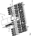
- a distribution machine 1 for spreading seeds and / or fertilizer on an agricultural area is shown in Fig.1 shown.
- the distribution machine 1 comprises a storage container 2, elongated in the direction of travel F, for the material to be dispensed.
- a concealed discharge device is arranged, which feeds material from the storage container 2 into a plurality of discharge lines, not shown.
- the distributing machine 2 further comprises a plurality of disc coulters 3.
- the disc coulters 3 are transverse to the direction of travel F arranged next to one another via a coulter arrangement 4 on a frame 5 of the distribution machine 1 and are thus moved through the soil of the agricultural area when the distribution machine 1 is in operation.
- the disc coulters 3 are each connected to the application device via one of the application lines (not shown).
- the frame 5 can be rotated so that the disc coulters 3 are carried at a different height in relation to the chassis of the distributing machine 1.
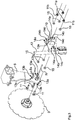
- FIG Fig. 2 One of the coulter arrangements 4 in the detached state from the distributor 1 is shown in FIG Fig. 2 shown.
- the coulter arrangement 4 for the disc coulter 3 designed as a fertilizer coulter is arranged via a bearing 6 on the frame 5 of the distributing machine 1 designed as a square tube and comprises, in addition to the coulter disk 3, a wedge-like furrow former 7.
- the bearing 6 has an upper bearing shell 6a and a lower bearing shell 6b , which are set up together to encompass the frame 5 so that the coulter arrangement 4 is carried on the frame 5.
- the upper and lower bearing shells 6a, b are releasably fastened to one another by means of fastening means designed as screw-nut connections and include elastic bearing elements 6c, which are designed as elongated round rubbers, for damping purposes.
- the lower bearing shell 6b is non-detachably connected to a support arm 8, at the lower end of which the coulter disk 3 is rotatably mounted about an axis of rotation R.
- the wedge-like furrow former 7 widens towards the rear in the direction of travel F, so that a furrow remains when moving through the ground, and is likewise fastened to the lower end of the support arm 8 by means of a holding device 9.
- the holding device 9 comprises a flange-like coulter carrier 10 which is not detachably connected to the furrow former 7.
- the furrow former 7 is fastened to the support arm 8 via the coulter carrier 10 by means of a total of three fastening bolts designed as screw bolts 11.
- the screw bolts 11 penetrate the support arm 8 at bores 8a and the coulter support 10 at recesses 10a brought into congruence with the bores 8a and are secured at their free end facing away from the coulter disk 3 with a nut 11a against unintentional shaking.
- the bolts 11 form in side view, transverse to Seen in the direction of travel, the corner points A, B, C of a triangle ABC.
- the attachment of the furrow former 7 to the support arm 8 is thus designed to be particularly tilt-proof and simple.
- the three screw bolts 11 arranged in the triangle ABC hold the furrow former 7 particularly reliably in contact with the coulter disc 3, so that the coulter arrangement 4 is characterized by a particularly reliable and constant quality of work.
- the coulter disc 3 is rotatably mounted on the support arm 8 within the triangle ABC, that is, the axis of rotation R lies within the triangle ABC and is at least approximately perpendicular to it.
- the furrow former 7 can be connected to the application lines (not shown) via the holding device 9, which is at least partially designed as a distribution line 12.
- the material discharged by the discharge device is then discharged at least partially via the pipe-like distribution line 12 to the furrow former 7, which is moved through the ground together with the coulter disc 3, and is thus worked into the ground via the furrow created.
- the holding device 9 is expediently made in one piece, that is to say not detachably connected, with the furrow former 7.
- the frame 5 of the distributing machine 1 can be rotated, as mentioned above. Due to the link-like connection of the coulter disc 3 and the furrow former 7 via the support arm 8 on the frame 5, these pivot upwards or downwards when the frame 5 is rotated, depending on the direction of rotation.
- the coulter disc 3 and the furrow former 7 are then carried at a different height in relation to the frame 5 or the chassis of the distributor 1, so that they have a different working depth. Since the furrow former 7 is rotated about the bearing 6 via the support arm 8 acting as a lever arm, the furrow former 7 is at a different angle to the ground.
- each of the drilling patterns 13a, 13b consists of three corresponding bores 8a, the bores 8a of the drilling pattern 13b running ahead of the drilling pattern 13a about the axis of rotation R clockwise in FIG Fig. 3 .
- the furrow former 7 can consequently be fastened to the support arm 8 in two different positions by means of the two drilling patterns 13a, 13b via the three screw bolts 11 by inserting the screw bolts 11 either through the bores 8a of one or the other drilling pattern 13a or 13b. In this way, an angle adjustment of the furrow former 7 to the support arm 8 or to the surface of the soil to be worked is realized.
- the furrow former 7 can consequently be attached to the support arm 8 via the drilling patterns 13a, 13b, adapted to the working depth of the coulter disc 3. With a given working depth of the coulter disc 3, the angle at which the support arm 8 stands to the ground via the bearing 6 on the frame 5 is known, so that the furrow former 7 can be aligned accordingly. In this way, the delivery angle of the seed and / or fertilizer supplied from the furrow former 7 via the tubular distribution line 12 can be adjusted, as can the shape of the furrow produced by the furrow former 7.
- the furrow former 7 can be fastened in a rotated position relative to the support arm 8 by means of the drilling patterns 13a, 13b.
- the arrangement of the drilling patterns 13a, 13b at a distance rotated about the axis of rotation R offers the advantage that the association between the furrow former 7 and the coulter disc 3 is hardly changed as a result.
- the support arm 8 has further drilling patterns 13a, 13b spaced apart in the vertical and / or horizontal direction.
- the coulter carrier 10 has three recess patterns 14a, 14b, 14c arranged at a distance from one another, such as Fig. 3 shows.
- Each of the recess images 14a, 14b, 14c is composed of three corresponding recesses 10a in the coulter carrier 10, the recesses 10a of the recess pattern 14a each being arranged in at least an approximately vertical direction above those of the recess patterns 14b, 14c, so that the furrow former 7 is carried on the coulter disc 3, offset radially outwards, when the Screw bolts 11 are guided through the recesses 10a of the recess pattern 14a.
- the recesses 10a of the recess pattern 14c are arranged corresponding to the opposite end position of the furrow former 7, near the axis of rotation R of the coulter disc 3, at the bottom of the coulter carrier 10, so that the furrow former 7 is offset radially inward on the coulter disc 3 from the support arm 8 or the screw bolts 11 is worn.
- the middle position of the furrow former 7 on the coulter disc 3 via the coulter carrier 10 attached to the support arm 8 is shown in FIG Fig. 4 shown in detail view.
- the screw bolts 11 reach through the support arm 8 in the drilling pattern 13b, which is brought into congruence with the recess pattern 14b in the coulter carrier 10, so that the furrow former 7 is supported on the coulter disc 3 at a medium distance from the axis of rotation R.
- the furrow former 7 can consequently be attached to the coulter disc in three different positions by means of the three recess patterns 14a-c via the screw bolts 11.
- the three positions of the furrow former 7 differ with regard to the distance at which it is carried to the axis of rotation R of the coulter disc 3 or the working depth at which the furrow former 7 operates relative to the coulter disc 3.
- the screw bolts 11 on both sides of the coulter support 10, that is, on the side of the coulter support 10 facing away from the support arm 8 and between the coulter support 10 and support arm 8, are each assigned an elastic spring element designed as a spring ring 15.
- the spring washers 15 are preferably made of an elastic plastic and are threaded onto the screw bolts 11 in the previously described arrangement in front of the nuts 11a so that the furrow former 7 is resiliently attached to the coulter disc 3 on the support arm 8.
- the spring washers 15 can be pre-tensioned in the direction of the coulter disk 3 by means of the nuts 11a, in that the nuts 11a are tightened onto the screw bolts 11 with a defined torque.
- the nuts 11a are integral with a Washer 11b executed.
- the washer 11b is pressed in the direction of the coulter support 10 or the support arm 8 by screwing on the nut 11a, since the screw bolts 11 are fixed on the opposite side of the support arm 8.
- the nut 11a acts as a tensioning body for the washer 11b, which serves as a pressure disk, in order to tension the spring washers 15.
- the spring washers 15 can consequently be impressed with a deformation defined via the tightening torque by the nuts 11a.
- the deformation is in turn a measure of the pretensioning force of the spring washers 15 in the direction of the coulter disc 3, so that the force with which the furrow former 7 is automatically held in contact with the coulter disc 3 via the spring washers 15 interacting with the screw bolts 11 can be set.
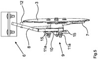
- Fig. 5 the coulter arrangement 4 can be seen in a front view against the direction of travel F.
- the furrow former 7 is held in contact with the coulter disc 3 via the holding device 9.
- the coulter disc 3 and the furrow former 7 are attached to the frame 5 of the distributing machine 1 via the bearing 6 and are moved together through the soil of the field to be worked.
- seed and / or fertilizer is discharged via the distribution line 12 into the furrow prepared by the furrow former 7 and thus worked into the soil.
- the arrangement of the furrow former 7 in relation to the support arm 8 can be adjusted by means of the drilling patterns 13a, 13b, so that the furrow former 7 can be carried at different angles to the ground.
- the distance between the furrow former 7 and the circumference of the coulter disc 3 by guiding the screw bolts 11 through one of the recess formers 14a-c.
- the working depth of the furrow former 7 is thus adjustable relative to the working depth of the coulter disc 3.
- the spring washers 15 By means of the spring washers 15, the furrow former 7 is automatically held in contact with the coulter disc 3 even with increasing wear.
- the furrow former 7 is set up by means of the spring rings 15 to give way in a springy manner when it hits obstacles in the ground, such as stones.
Landscapes
- Life Sciences & Earth Sciences (AREA)
- Soil Sciences (AREA)
- Environmental Sciences (AREA)
- Sowing (AREA)
Abstract
Scharanordnung (4) für ein Scheibenschar (3), insbesondere Düngerschar, umfassend eine am unteren Ende eines Tragarms (8) drehbar gelagerte Scharscheibe (3) und einen mittels einer Haltevorrichtung (9) am unteren Ende des Tragarms (8) angeordneten Furchenformer (7), wobei die Scharanordnung (4) über das obere Ende des Tragarms (8) an einem, insbesondere drehbaren, Rahmen (5) einer Verteilmaschine (1) anordbar ist, wobei die Haltervorrichtung (9) einen Scharträger (10) aufweist und der Furchenformer (7) über den Scharträger (10) mittels zumindest zwei beabstandet zueinander angeordneten, insbesondere als Schraubbolzen (11) ausgeführten, den Scharträger (10) und den Tragarm (8) durchsetzenden Befestigungsbolzen (11) am Tragarm (8) befestigt ist. Um eine einfache und sichere Befestigung für eine definierte Zuordnung des Furchenformers (7) an der Scharscheibe (3) zu schaffen, ist vorgesehen, dass zumindest drei Befestigungsbolzen (11) vorgesehen sind, dass die zumindest drei Befestigungsbolzen (11) die Eckpunkte (A, B, C) eines Dreiecks (ABC) bildend angeordnet sind.Coulter arrangement (4) for a disc coulter (3), in particular a fertilizer coulter, comprising a coulter disc (3) rotatably mounted on the lower end of a support arm (8) and a furrow former (7) arranged by means of a holding device (9) on the lower end of the support arm (8) ), the coulter arrangement (4) being able to be arranged via the upper end of the support arm (8) on an, in particular rotatable, frame (5) of a distributing machine (1), the holder device (9) having a coulter support (10) and the furrow former (7) via the coulter support (10) by means of at least two spaced apart, in particular designed as screw bolts (11), the coulter support (10) and the support arm (8) penetrating fastening bolts (11) on the support arm (8). In order to create a simple and secure fastening for a defined assignment of the furrow former (7) to the coulter disc (3), it is provided that at least three fastening bolts (11) are provided, that the at least three fastening bolts (11) the corner points (A, B, C) are arranged to form a triangle (ABC).
Description
Die Erfindung betrifft eine Scharanordnung gemäß dem Oberbegriff des Patentanspruches 1 und eine Verteilmaschine mit einer Scharanordnung gemäß dem Oberbegriff des Patentanspruches 10.The invention relates to a coulter arrangement according to the preamble of patent claim 1 and a distributing machine with a coulter arrangement according to the preamble of
Eine derartige Scharanordnung und eine Verteilmaschine sind in
Zur Befestigung des Furchenformers am Tragarm weist die Haltevorrichtung einen plattenartigen Scharträger auf, welcher an dem Furchenformer befestigt ist und diesen so trägt. Der Furchenformer ist über den Scharträger mittels zwei beabstandet zueinander angeordneten Befestigungsbolzen am Tragarm lösbar befestigt. Die Befestigungsbolzen sind als Schraubbolzen ausgeführt und durchsetzen den Tragarm und den Scharträger an dafür vorgesehenen Bohrungen. Mit Hilfe zweier auf die Schraubbolzen aufschraubbarer, als Sicherungsmuttern ausgeführter Sicherungselemente mit zugeordneten Unterlegscheiben gegen ungewolltes Lösen der Sicherungselemente ist der Scharträger lösbar am Tragarm festgelegt.To attach the furrow former to the support arm, the holding device has a plate-like coulter carrier which is attached to the furrow former and thus supports it. The furrow former is releasably fastened to the support arm via the coulter carrier by means of two fastening bolts arranged at a distance from one another. The fastening bolts are designed as screw bolts and penetrate the support arm and the coulter carrier at the holes provided for this purpose. The coulter carrier is releasably secured to the support arm with the aid of two securing elements, which can be screwed onto the screw bolts and are designed as securing nuts, with associated washers to prevent the securing elements from being accidentally released.
Nachteilig bei dieser Scharanordnung ist, dass die beiden Befestigungsbolzen eine Achse bilden, um die der Furchenformer sich gegenüber dem Tragarm und insbesondere der Scharscheibe verschwenken kann. Die Lagerung des Furchenformers ist somit in axialer Richtung unterbestimmt, so dass keine sichere Anordnung des Furchenformers relativ zur Scharscheibe möglich ist. Dies ist besonders nachteilig, da angestrebt wird den Furchenformer zumindest annährend in Anlage zur Scharscheibe zu halten, um mittels der Scharanordnung definierte Ablagebedingungen für Saatgut und/oder Dünger für die Verteilmaschine zu schaffen.The disadvantage of this coulter arrangement is that the two fastening bolts form an axis about which the furrow former can pivot with respect to the support arm and in particular the coulter disc. The storage of the furrow former is thus under-determined in the axial direction, so that a secure arrangement of the furrow former relative to the coulter disc is not possible. This is particularly disadvantageous since the aim is to keep the furrow former at least approximately in contact with the coulter disc in order to create defined storage conditions for seeds and / or fertilizer for the distributor by means of the coulter arrangement.
Die der Erfindung zugrunde liegende Aufgabe besteht somit darin, eine einfache und sichere Befestigung für eine definierte Zuordnung des Furchenformers an der Scharscheibe zu schaffen.The object on which the invention is based is thus to create a simple and secure attachment for a defined assignment of the furrow former to the coulter disc.
Diese Aufgabe wird erfindungsgemäß dadurch gelöst, dass zumindest drei Befestigungsbolzen vorgesehen sind, wobei die zumindest drei Befestigungsbolzen die Eckpunkte eines Dreiecks bildend angeordnet sind.This object is achieved according to the invention in that at least three fastening bolts are provided, the at least three fastening bolts being arranged so as to form the corner points of a triangle.
Infolge dieser Maßnahme ist eine kippsichere Befestigung des Furchenformers am Tragarm geschaffen. Durch die drei im Dreieck zueinander angeordneten Befestigungsbolzen ist eine bestimmte Lagerung des Furchenformers am Tragarm erreicht, so dass eine definierte Anordnung des Furchenformers relativ zur Scharscheibe ermöglicht ist. Die Erfindung macht sich die Erkenntnis zunutze, dass durch die Anordnung zumindest eines dritten Befestigungsbolzens, der nicht auf der Achse zwischen den anderen beiden Befestigungsbolzen liegt, in besonders einfacher und zweckmäßiger Weise eine sichere Befestigung für die definierte Zuordnung des Furchenformers an der Scharscheibe geschaffen ist.As a result of this measure, a tilt-proof fastening of the furrow former on the support arm is created. The three fastening bolts arranged in a triangle with respect to one another achieve a specific mounting of the furrow former on the support arm, so that a defined arrangement of the furrow former relative to the coulter disc is made possible. The invention makes use of the knowledge that the arrangement of at least one third fastening bolt, which is not on the axis between the other two fastening bolts, creates a secure fastening for the defined assignment of the furrow former to the coulter disc in a particularly simple and expedient manner.
In einer vorteilhaften Weiterbildung der Scharanordnung ist vorgesehen, dass den zumindest drei Befestigungsbolzen auf der dem Tragarm abgewandten Seite des Scharträgers und zwischen Scharträger und Tragarm, vorzugsweise jeweils und/oder auf jeder Seite des Scharträgers, zumindest ein elastisches Federelement zugeordnet ist. Der Einsatz elastischer Federelemente erlaubt es, dass der Furchenformer über den Scharträger mittels der Federelemente sich der Kontur der Scharscheibe anpassen kann. In vorteilhafter Weise ist die Zuordnung des Furchenformers an der Scharscheibe somit weiter verbessert. Die Federelemente können als elastische, zumindest annährend ringförmige Gummischeiben ausgeführt sein, welche eine Ausnehmung zum Auffädeln des Federelementes auf einen Befestigungsbolzen aufweisen. Die Federelemente können als mattenartiges Scheibenelement ausgeführt sein, welches zumindest drei Ausnehmungen zum Auffädeln auf die zumindest drei Befestigungsbolzen aufweist.In an advantageous development of the coulter arrangement it is provided that at least one elastic spring element is assigned to the at least three fastening bolts on the side of the coulter carrier facing away from the support arm and between the coulter carrier and the carrier arm, preferably in each case and / or on each side of the coulter carrier. The use of elastic spring elements allows the furrow former to move over the coulter carrier by means of the spring elements Can adapt the contour of the coulter disc. The assignment of the furrow former to the coulter disc is thus further improved in an advantageous manner. The spring elements can be designed as elastic, at least approximately ring-shaped rubber disks which have a recess for threading the spring element onto a fastening bolt. The spring elements can be designed as a mat-like disc element which has at least three recesses for threading onto the at least three fastening bolts.
Um die Anordnung des Furchenformers relativ zur Scharscheibe weiter zu verbessern, ist in einer weiteren vorteilhaften Weiterbildung der Scharanordnung die Scharscheibe zumindest annährend innerhalb des von den Befestigungsbolzen aufgespannten Dreiecks am Tragarm drehbar gelagert. Die zumindest drei Befestigungsbolzen, welche die Eckpunkte eines Dreiecks bilden, durchsetzen den Tragarm und spannen somit zwischen sich ein Dreieck am Tragarm auf. Durch die Lagerung der Scharscheibe zumindest annährend innerhalb dieses Dreiecks liegt die Drehachse der Scharscheibe ebenfalls innerhalb dieses Dreiecks. Untersuchungen haben gezeigt, dass eine derartige Anordnung besonders robust gegen Erschütterungen und Vibrationen ist, so dass die Anordnung des Furchenformers relativ zur Scharscheibe besonders im bodeneingreifenden Betrieb verbessert ist. Diese Weiterbildung zeichnet sich folglich durch eine besonders sichere und robuste Lagerung der Scharscheibe aus.In order to further improve the arrangement of the furrow former relative to the coulter disc, in a further advantageous development of the coulter arrangement the coulter disc is rotatably mounted on the support arm at least approximately within the triangle spanned by the fastening bolts. The at least three fastening bolts, which form the corner points of a triangle, penetrate the support arm and thus span a triangle on the support arm between them. Because the coulter disc is mounted at least approximately within this triangle, the axis of rotation of the coulter disc also lies within this triangle. Investigations have shown that an arrangement of this type is particularly robust against shocks and vibrations, so that the arrangement of the furrow former relative to the coulter disc is improved, especially in operation that engages the ground. This development is consequently characterized by a particularly secure and robust mounting of the coulter disc.
In einer weiteren vorteilhaften Weiterbildung der Erfindung ist vorgesehen, dass der Scharträger zumindest zwei beabstandet zueinander angeordnete Ausnehmungsbilder mit jeweils zumindest drei von den Befestigungsbolzen durchsetzbaren Ausnehmungen aufweist, dass der Furchenformer mittels der zumindest zwei Ausnehmungsbilder über die zumindest drei Befestigungsbolzen in zumindest zwei unterschiedlichen Lagen zur Scharscheibe befestigbar ist. Vorzugsweise sind die Ausnehmungsbilder in unterschiedlichem Abstand zum Mittelpunkt der Scharscheibe angeordnet, so dass der Furchenformer relativ zur Scharscheibe in unterschiedlichen Positionen am Tragarm befestigbar ist. Infolge dieser Maßnahme ist die Arbeitstiefe des Furchenformers relativ zur Arbeitstiefe der Scharscheibe einstellbar.In a further advantageous development of the invention it is provided that the coulter carrier has at least two spaced apart recess images with at least three recesses penetrable by the fastening bolts, that the furrow former by means of the at least two recess images via the at least three fastening bolts in at least two different positions to the coulter disc is attachable. The recess images are preferably arranged at different distances from the center point of the coulter disc, so that the furrow former can be fastened to the support arm in different positions relative to the coulter disc. As a result This measure enables the working depth of the furrow former to be adjusted relative to the working depth of the coulter disc.
Die Scharanordnung ist ferner vorteilhaft dadurch weitergebildet, dass der Tragarm zumindest zwei beabstandet zueinander angeordnete Bohrbilder mit jeweils zumindest drei von den Befestigungsbolzen durchsetzbaren Bohrungen aufweist, wobei der Furchenformer mittels der zumindest zwei Bohrbilder über die zumindest drei Befestigungsbolzen in zumindest zwei unterschiedlichen Lagen zum Tragarm befestigbar ist. Vorzugsweise sind die Bohrbilder kreisförmig um den Mittelpunkt der Scharscheibe angeordnet, so dass der Furchenformer in den unterschiedlichen Lagen zum Tragarm gegenüber der Drehachse der Scharscheibe verdreht wird, so dass sich die Anordnung des Furchenformers relativ zur Scharscheibe nahezu nicht ändert. Die Arbeitstiefe der Scharscheibe kann verändert werden, indem der Tragarm verschwenkt wird. Es ist denkbar, dass der Rahmen zumindest teilweise drehbar ist, so dass der Tragarm durch Drehung des Rahmenteils, an dem er befestigt ist, verschwenkbar ist. Hierbei verändert sich die Orientierung des Furchenformers zur zu bearbeitenden Bodenoberfläche. Um diese veränderte Orientierung zu berücksichtigen, ist der Furchenformer mittels der zumindest zwei Bohrbilder in angepasster Lage zum Tragarm befestigbar, wobei sich die Zuordnung zur Scharscheibe zumindest annährend nicht ändert. Durch diese Weiterbildung ist folglich in zweckmäßiger Weise eine Anpassungsmöglichkeit zur Einstellung der Arbeitstiefe der Scharscheibe gemeinsam mit dem Furchenformer geschaffen. Ferner ist infolge dieser Maßnahme der Winkel des Furchenformers zur Bodenoberfläche einstellbar, indem der Furchenformer in veränderter Lage zum Tragarm befestigt wird, wobei der Tragarm nicht verschwenkt wird. Um den Furchenformer in einer Mehrzahl unterschiedlicher Lagen, insbesondere Winkellagen, gegenüber dem Tragarm zu befestigen, kann der Tragarm mehr als zwei beabstandet zueinander angeordnete Bohrbilder aufweisen.The coulter arrangement is also advantageously further developed in that the support arm has at least two spaced apart drilling patterns, each with at least three bores penetrable by the fastening bolts, the furrow former being attachable to the support arm in at least two different positions by means of the at least two drilling patterns via the at least three fastening bolts . The drilling patterns are preferably arranged in a circle around the center of the coulter disc, so that the furrow former is rotated in the different positions to the support arm relative to the axis of rotation of the coulter disc, so that the arrangement of the furrow former relative to the coulter disc hardly changes. The working depth of the coulter disc can be changed by pivoting the support arm. It is conceivable that the frame is at least partially rotatable, so that the support arm can be pivoted by rotating the frame part to which it is attached. This changes the orientation of the furrow former to the soil surface to be worked. In order to take this changed orientation into account, the furrow former can be fastened in an adapted position to the support arm by means of the at least two drilling patterns, the assignment to the coulter disc not changing at least approximately. As a result of this development, an adjustment option for setting the working depth of the coulter disc together with the furrow former is consequently created in an expedient manner. Furthermore, as a result of this measure, the angle of the furrow former to the ground surface can be adjusted in that the furrow former is fastened in a different position to the support arm, the support arm not being pivoted. In order to fasten the furrow former in a plurality of different positions, in particular angular positions, with respect to the support arm, the support arm can have more than two drilling patterns arranged at a distance from one another.
In einer weiteren vorteilhaften Weiterbildung der Scharanordnung sind die Federelemente in Richtung der Scharscheibe wirkend vorspannbar, wobei zumindest einem Befestigungsbolzen Mittel, die dazu eingerichtet sind, die dem Befestigungsbolzen zugeordneten Federelemente einstellbar vorzuspannen, zugeordnet sind. Durch die Vorspannung der Federelemente ist die Kraft einstellbar mit der der Furchenformer zur Scharscheibe am Tragarm gehalten wird. Ist durch Betätigung der Mittel eine hohe Vorspannung der Federelemente eingestellt, ist die Befestigung des Furchenformers besonders starr. Bei geringer Vorspannung ist die Anordnung des Furchenformers am Tragarm zumindest teilweise elastisch.In a further advantageous development of the coulter arrangement, the spring elements can be pretensioned to act in the direction of the coulter disc, with at least one fastening bolt means which are set up to adjustably bias the spring elements assigned to the fastening bolt assigned. The force with which the furrow former is held to the coulter disc on the support arm can be adjusted by the bias of the spring elements. If a high bias of the spring elements is set by actuating the means, the fastening of the furrow former is particularly rigid. If the preload is low, the arrangement of the furrow former on the support arm is at least partially elastic.
In einer weiteren besonders vorteilhaften Weiterbildung der Scharanordnung ist vorgesehen, dass die Mittel zumindest eine Druckscheibe und zumindest einen Spannkörper umfassen, dass die Druckscheibe mittels des Spannkörpers gegen den Scharträger und/oder den Tragarm pressbar ist. Vorzugsweise ist der Spannkörper als auf einen als Schraubbolzen ausgeführten Befestigungsbolzen aufschraubbare Spannmutter ausgeführt. Die Druckscheibe ist vorzugsweise als auf einen Befestigungsbolzen aufschiebbare Unterlegscheibe ausgeführt. Die Druckscheibe und der Spannkörper können einstückig, also nicht lösbar verbunden, ausgeführt sein. Vorzugsweise ist der Spannkörper lösbar an einem Befestigungsbolzen festlegbar, so dass die Vorspannung eines Federelementes durch Festlegen des Spannkörpers in einer bestimmten Position, welche eine damit korrespondierende vorzugsweise elastische Verformung des Federelementes hervorruft, einstellbar ist. Infolge dieser Maßnahme ist die Vorspannung der Federelemente über das Maß mit dem die Druckscheibe mittels des Spannkörpers angepresst wird einstellbar.In a further particularly advantageous development of the coulter arrangement it is provided that the means comprise at least one pressure disc and at least one clamping body, so that the pressure disc can be pressed against the coulter carrier and / or the support arm by means of the clamping body. The clamping body is preferably designed as a clamping nut that can be screwed onto a fastening bolt designed as a screw bolt. The pressure disk is preferably designed as a washer which can be pushed onto a fastening bolt. The thrust washer and the clamping body can be designed in one piece, that is, not detachably connected. The tensioning body can preferably be releasably fixed to a fastening bolt, so that the pretensioning of a spring element can be adjusted by fixing the tensioning body in a certain position, which causes a corresponding, preferably elastic, deformation of the spring element. As a result of this measure, the preload of the spring elements can be adjusted to the extent with which the pressure disk is pressed by means of the clamping body.
In einer weiteren vorteilhaften Weiterbildung der Scharanordnung ist vorgesehen, dass der Furchenformer mittels der Federelemente zumindest annährend selbsttätig in Anlage an die Scharscheibe gehalten ist. Im Betrieb wird der Furchenformer am Tragarm befestigt durch den Boden geführt und erfährt so einen abrasiven Verschleiß. Vorteilhaft ist hierbei, dass infolge dieser Maßnahme die Befestigung so weitergebildet ist, dass sie sich mit fortschreitendem Verschleiß des Furchenformers selbsttätig nachstellt, das heißt den Furchenformer bei abnehmender Materialstärke desselbigen zumindest annährend in Anlage zur Scharscheibe hält. Dies ist besonders zweckmäßig, da dadurch das Risiko von Verstopfungen zwischen Furchenformer und Scharscheibe durch Pflanzenrückstände reduziert ist.In a further advantageous development of the coulter arrangement it is provided that the furrow former is at least approximately automatically held in contact with the coulter disc by means of the spring elements. During operation, the furrow former is attached to the support arm and guided through the ground and thus experiences abrasive wear. The advantage here is that, as a result of this measure, the attachment is further developed so that it automatically readjusts itself as the furrow former becomes worn, i.e. keeps the furrow former at least approximately in contact with the coulter disc as the material thickness decreases. This is particularly useful as it reduces the risk of blockages between the furrow former and the coulter disc due to plant residues.
Die Scharanordnung ist außerdem vorteilhaft dadurch weitergebildet, dass der Furchenformer mittels der den zumindest drei Befestigungsbolzen zugeordneten Federelemente zumindest teilweise federnd, insbesondere gegenüber der Scharscheibe, ausweichbar an dem Tragarm befestigt ist. Um Beschädigungen der Scharanordnung bei der Bearbeitung steiniger Böden zu vermeiden, ist infolge dieser Weiterbildung eine Scharanordnung geschaffen, dessen Furchenformer dazu eingerichtet ist, Ausweichbewegungen, insbesondere quer zur Fahrtrichtung, auszuführen, so dass beim Auftreffen auf im Boden befindliche Hindernisse Beschädigungen zumindest teilweise vermieden werden.The coulter arrangement is also advantageously further developed in that the furrow former is at least partially resiliently attached to the support arm by means of the spring elements associated with the at least three fastening bolts, in particular in relation to the coulter disc. In order to avoid damage to the coulter arrangement when working on stony soils, a coulter arrangement is created as a result of this development, the furrow former of which is designed to perform evasive movements, in particular transverse to the direction of travel, so that damage is at least partially avoided when hitting obstacles in the ground.
In einer weiteren vorteilhaften Weiterbildung der Scharanordnung ist die Haltervorrichtung einstückig mit dem Furchenformer ausgeführt, wobei die Haltevorrichtung zumindest teilweise als Verteilleitung ausgeführt ist. Um Saatgut und/oder Dünger direkt in die dafür vorgesehene vom Furchenformer geschaffene Furche abzugeben, ist es zweckmäßig, dass die Haltevorrichtung zumindest teilweise als Verteilleitung nutzbar ist. Vorzugsweise ist das untere Ende der Haltevorrichtung als Verteilleitung ausgeführt. Das Material kann somit besonders nah an gewünschter Stelle abgegeben werden und eine zusätzliche Verteilleitung kann zumindest teilweise entfallen. In vorteilhafter Weise ist die Haltevorrichtung so doppelt nutzbar. Weiter vorteilhaft ist, dass durch die Ausführung der Haltevorrichtung mit dem Furchenformer als ein Teil, der Furchenformer nicht verlierbar am Tragarm befestigt ist.In a further advantageous development of the coulter arrangement, the holding device is designed in one piece with the furrow former, the holding device being at least partially designed as a distribution line. In order to deliver seeds and / or fertilizer directly into the intended furrow created by the furrow former, it is expedient for the holding device to be at least partially usable as a distribution line. The lower end of the holding device is preferably designed as a distribution line. The material can thus be delivered particularly close to the desired point and an additional distribution line can at least partially be omitted. In an advantageous manner, the holding device can be used twice. It is further advantageous that by designing the holding device with the furrow former as one part, the furrow former is secured to the support arm so that it cannot be lost.
Die der Erfindung zugrunde liegende Aufgabe wird ferner durch eine Verteilmaschine der eingangs genannten Art gelöst, wobei die Verteilmaschine zumindest ein über eine Scharanordnung an einem Rahmen der Verteilmaschine angeordnetes Scheibenschar umfasst und die Scharanordnung nach zumindest einer der vorstehend beschriebenen Ausführungsformen ausgeführt ist. Bezüglich der Vorteile und Modifikationen der erfindungsgemäßen Verteilmaschine wird auf die Vorteile und Modifikationen der erfindungsgemäßen Scharanordnung verwiesen.The object on which the invention is based is also achieved by a distributing machine of the type mentioned at the outset, the distributing machine comprising at least one disc coulter arranged on a frame of the distributing machine via a coulter arrangement and the coulter arrangement being designed according to at least one of the embodiments described above. With regard to the advantages and modifications of the distributing machine according to the invention, reference is made to the advantages and modifications of the coulter arrangement according to the invention.
In einer vorteilhaften Weiterbildung der Verteilmaschine ist die Arbeitstiefe des Scheibenschars mittels Verdrehung des Rahmens einstellbar, wobei der Furchenformer über die zumindest zwei Bohrbilder des Tragarms an die Arbeitstiefe der Scharscheibe angepasst am Tragarm befestigbar ist. Um bei Verschwenken des Tragarms durch Verdrehung des Rahmens, den Winkelfehler des Furchenformers auszugleichen, kann der Furchenformer über die zumindest zwei Bohrbilder in um den Mittelpunkt der Scheibe gedrehter Lage am Tragarm befestigt werden.In an advantageous further development of the distributor, the working depth of the disc coulter can be adjusted by rotating the frame, the furrow former being able to be attached to the support arm via the at least two drilling patterns of the support arm, adapted to the working depth of the coulter disc. In order to compensate for the angular error of the furrow former when the support arm is pivoted by rotating the frame, the furrow former can be attached to the support arm via the at least two drilling patterns in a position rotated around the center of the disk.
Weitere Einzelheiten der Erfindung sind der Beispielsbeschreibung und den Zeichnungen zu entnehmen. Die Zeichnungen zeigen
- Fig.1
- eine Verteilmaschine mit einer Mehrzahl über erfindungsgemäße Scharanordnungen angeordneter Scheibenschare in perspektivischer Ansicht,
- Fig.2
- eine der Scharanordnungen aus
Fig.1 in von der Verteilmaschine demontiertem Zustand in perspektivischer Ansicht, - Fig.3
- die Scharanordnung aus
Fig.2 in Explosionsdarstellung, - Fig.4
- die Scharanordnung aus
Fig.2 in Detailansicht, und - Fig.5
- die Scharanordnung aus
Fig.2 in Frontansicht.
- Fig.1
- a distributing machine with a plurality of disc coulters arranged over coulter arrangements according to the invention in a perspective view,
- Fig. 2
- select one of the coulter arrangements
Fig.1 in the dismantled state from the distributor in a perspective view, - Fig. 3
- the coulter arrangement
Fig. 2 in exploded view, - Fig. 4
- the coulter arrangement
Fig. 2 in detail view, and - Fig. 5
- the coulter arrangement
Fig. 2 in front view.
Eine Verteilmaschine 1 zum Ausbringen von Saatgut und/oder Dünger auf einer landwirtschaftlichen Nutzfläche ist in
Eine der Scharanordnungen 4 in von der Verteilmaschine 1 gelöstem Zustand ist in
Die untere Lagerschale 6b ist nicht lösbar mit einem Tragarm 8 verbunden, an dessen unteren Ende die Scharscheibe 3 drehbar um eine Rotationsachse R gelagert ist. Der keilartige Furchenformer 7 verbreitert sich in Fahrtrichtung F nach hinten, so dass eine Furche bei Bewegung durch den Boden zurückbleibt, und ist mittels einer Haltevorrichtung 9 ebenfalls am unteren Ende des Tragarms 8 befestigt. Die Haltevorrichtung 9 umfasst einen flanschartigen Scharträger 10, der nicht lösbar mit dem Furchenformer 7 verbunden ist. Der Furchenformer 7 ist über den Scharträger 10 mittels insgesamt drei als Schraubbolzen 11 ausgeführten Befestigungsbolzen am Tragarm 8 befestigt. Die Schraubbolzen 11 durchsetzen den Tragarm 8 an Bohrungen 8a und den Scharträger 10 an mit den Bohrungen 8a in Deckung gebrachten Ausnehmungen 10a und sind an ihrem freien, der Scharscheibe 3 abgewandten Ende mit einer Mutter 11a gegen ungewolltes Losrütteln gesichert. Die Schraubbolzen 11 bilden in Seitenansicht, quer zur Fahrrichtung gesehen die Eckpunkte A, B, C eines Dreiecks ABC. Die Befestigung des Furchenformers 7 am Tragarm 8 ist somit besonders kippsicher und einfach gestaltet. Durch die drei im Dreieck ABC angeordneten Schraubbolzen 11 ist der Furchenformer 7 besonders zuverlässig in Anlage zur Scharscheibe 3 gehalten, so dass die Scharanordnung 4 sich durch besonders zuverlässige und gleichbleibende Arbeitsqualität auszeichnet. Die Scharscheibe 3 ist innerhalb des Dreieckts ABC am Tragarm 8 drehbar gelagert, das heißt die Rotationsachse R liegt innerhalb des Dreiecks ABC und steht zumindest annährend senkrecht zu diesem.The
Um im Betrieb der Verteilmaschine 1 Saatgut und/oder Dünger zu verteilen, ist der Furchenformer 7 über die zumindest teilweise als Verteilleitung 12 ausgeführte Haltevorrichtung 9 mit den nicht dargestellten Ausbringleitungen verbindbar. Das von der Ausbringeinrichtung abgegebene Material wird dann zumindest teilweise über die rohrartige Verteilleitung 12 an dem mit der Scharscheibe 3 gemeinsam durch den Boden bewegten Furchenformer 7 abgegeben und so über die geschaffene Furche in den Boden eingearbeitet. Da der Furchenformer 7 im Bodenkontakt erhebliche Widerstandskräfte erfährt, ist die Haltevorrichtung 9 zweckmäßiger Weise einstückig, das heißt nicht lösbar verbunden, mit dem Furchenformer 7 ausgeführt.In order to distribute seed and / or fertilizer during operation of the distribution machine 1, the furrow former 7 can be connected to the application lines (not shown) via the
Um die Arbeitstiefe der der Scharscheibe 3 und des Furchenformers 7 gemeinsam zu verändern kann der Rahmen 5 der Verteilmaschine 1, wie vorstehend erwähnt, gedreht werden. Durch die lenkerartige Anbindung der Scharscheibe 3 und des Furchenformers 7 über den Tragarm 8 an dem Rahmen 5 schwenken diese bei Drehung des Rahmens 5 je nach Drehrichtung nach oben bzw. unten. Die Scharscheibe 3 und der Furchenformer 7 werden dann gegenüber dem Rahmen 5 bzw. dem Fahrwerk der Verteilmaschine 1 in veränderter Höhe getragen, so dass sie eine veränderte Arbeitstiefe aufweisen. Da der Furchenformer 7 dabei über den als Hebelarm wirkenden Tragarm 8 um die Lagerung 6 gedreht wird, steht der Furchenformer 7 in verändertem Winkel zum Untergrund.In order to change the working depth of the
Um den Winkel in dem der Furchenformer 7 gegenüber dem Tragarm 8 getragen wird einzustellen, ist vorgesehen, dass der Tragarm 8 zwei beabstandet zueinander um die Rotationsachse R der Scharscheibe 3 gedrehte Bohrbilder 13a, 13b aufweist, wie
Der Furchenformer 7 kann mittels der Bohrbilder 13a, 13b gegenüber dem Tragarm 8 in verdrehter Position befestigt werden. Um einen größeren Einstellbereich abzudecken, kann es zweckmäßig sein mehr als zwei beabstandete Bohrbilder 13a, 13b am Tragarm 8 vorzusehen und/oder diese in verändertem Abstand zueinander anzuordnen. Die Anordnung der Bohrbilder 13a, 13b in um die Rotationsachse R gedrehtem Abstand bietet den Vorteil, dass die Zuordnung zwischen dem Furchenformer 7 und der Scharscheibe 3 hierdurch nahezu nicht verändert wird. In einer nicht gezeigten Ausführungsform weist der Tragarm 8 weitere in vertikaler und/oder horizontaler Richtung beabstandete Bohrbilder 13a, 13b auf.The furrow former 7 can be fastened in a rotated position relative to the
Um die Höhe in der der Furchenformer 7 gegenüber der Scharscheibe 3 am Tragarm 8 getragen ist einzustellen, ist vorgesehen, dass der Scharträger 10 drei beabstandet zueinander angeordnete Ausnehmungsbilder 14a, 14b, 14c aufweist, wie
Wie in
Die Federringe 15 sind mittels der Muttern 11a in Richtung der Scharscheibe 3 wirkend vorspannbar, indem die Muttern 11a mit definiertem Drehmoment auf den Schraubbolzen 11 angezogen werden. Die Muttern 11a sind einstückig mit einer Unterlegscheibe 11b ausgeführt. Die Unterlegscheibe 11b wird durch Aufschrauben der Mutter 11a in Richtung des Scharträgers 10 bzw. des Tragarms 8 gepresst, da die Schraubbolzen 11 auf der gegenüberliegenden Seite des Tragarms 8 festgelegt sind. Die Mutter 11a wirkt insofern als Spannkörper für die als Druckscheibe dienende Unterlegscheibe 11b, um die Federringe 15 zu verspannen. Den Federringen 15 lässt sich folglich durch die Muttern 11a eine über das Anziehdrehmoment definierte Verformung aufprägen. Die Verformung ist wiederum ein Maß für die Vorspannkraft der Federringe 15 in Richtung der Scharscheibe 3, so dass einstellbar ist, mit welcher Kraft der Furchenformer 7 über die mit den Schraubbolzen 11 zusammenwirkenden Federringe 15 selbsttätig in Anlage an die Scharscheibe 3 gehalten wird.The spring washers 15 can be pre-tensioned in the direction of the
In
- 11
- VerteilmaschineDistribution machine
- FF.
- FahrtrichtungDirection of travel
- 22
- VorratsbehälterStorage container
- 33
- Scheibenschar, ScharscheibeDisc coulter, coulter disc
- 44th
- ScharanordnungCoulter arrangement
- 55
- Rahmenframe
- 66th
- Lagerungstorage
- 6a6a
- obere Lagerschaleupper bearing shell
- 6b6b
- untere Lagerschalelower bearing shell
- 77th
- FurchenformerFurrow former
- 88th
- TragarmBeam
- 8a8a
- Bohrungdrilling
- RR.
- RotationsachseAxis of rotation
- 99
- HaltevorrichtungHolding device
- 1010
- ScharträgerSharpener
- 10a10a
- AusnehmungRecess
- 1111
- SchraubbolzenBolt
- 11a11a
- Muttermother
- 11b11b
- UnterlegscheibeWasher
- A,B,CABC
- EckpunktCorner point
- ABCABC
- Dreiecktriangle
- 1212
- VerteilleitungDistribution line
- 13a,b13a, b
- BohrbildDrilling pattern
- 14a-c14a-c
- AusnehmungsbildRecess image
- 1515th
- FederringSpring washer
Claims (12)
Applications Claiming Priority (1)
| Application Number | Priority Date | Filing Date | Title |
|---|---|---|---|
| DE102019105624.1A DE102019105624A1 (en) | 2019-03-06 | 2019-03-06 | Coulter arrangement and distributor with a coulter arrangement |
Publications (1)
| Publication Number | Publication Date |
|---|---|
| EP3704922A1 true EP3704922A1 (en) | 2020-09-09 |
Family
ID=69528742
Family Applications (1)
| Application Number | Title | Priority Date | Filing Date |
|---|---|---|---|
| EP20401005.2A Pending EP3704922A1 (en) | 2019-03-06 | 2020-01-22 | Coulter assembly and distribution machine with same assembly |
Country Status (2)
| Country | Link |
|---|---|
| EP (1) | EP3704922A1 (en) |
| DE (1) | DE102019105624A1 (en) |
Citations (4)
| Publication number | Priority date | Publication date | Assignee | Title |
|---|---|---|---|---|
| WO1988005997A1 (en) * | 1987-02-19 | 1988-08-25 | Kurt Hansson | Agricultural combined drill dispenser |
| DE102006007624A1 (en) * | 2006-02-18 | 2007-08-23 | Rauch Landmaschinenfabrik Gmbh | Sowing machine for serial placing of seeds in ground, has sowing plough with plough disk which protect outflow opening of seeds guidance on side opposite to plough disk |
| WO2010138068A1 (en) * | 2009-05-29 | 2010-12-02 | Väderstad-Verken Aktiebolag | Disc for an agricultural implement |
| WO2014105560A2 (en) * | 2012-12-27 | 2014-07-03 | Agco-Amity Jv, Llc | Seed boot mounting |
Family Cites Families (1)
| Publication number | Priority date | Publication date | Assignee | Title |
|---|---|---|---|---|
| US7357193B2 (en) * | 2005-09-19 | 2008-04-15 | Air Design, Inc. | Air seeder disc scraper |
-
2019
- 2019-03-06 DE DE102019105624.1A patent/DE102019105624A1/en active Pending
-
2020
- 2020-01-22 EP EP20401005.2A patent/EP3704922A1/en active Pending
Patent Citations (5)
| Publication number | Priority date | Publication date | Assignee | Title |
|---|---|---|---|---|
| WO1988005997A1 (en) * | 1987-02-19 | 1988-08-25 | Kurt Hansson | Agricultural combined drill dispenser |
| DE102006007624A1 (en) * | 2006-02-18 | 2007-08-23 | Rauch Landmaschinenfabrik Gmbh | Sowing machine for serial placing of seeds in ground, has sowing plough with plough disk which protect outflow opening of seeds guidance on side opposite to plough disk |
| WO2010138068A1 (en) * | 2009-05-29 | 2010-12-02 | Väderstad-Verken Aktiebolag | Disc for an agricultural implement |
| EP2434860B1 (en) | 2009-05-29 | 2018-10-10 | Väderstad Holding AB | Disc for an agricultural implement |
| WO2014105560A2 (en) * | 2012-12-27 | 2014-07-03 | Agco-Amity Jv, Llc | Seed boot mounting |
Also Published As
| Publication number | Publication date |
|---|---|
| DE102019105624A1 (en) | 2020-09-10 |
Similar Documents
| Publication | Publication Date | Title |
|---|---|---|
| DE69813590T2 (en) | PLANTING UNIT | |
| EP0673592B1 (en) | Sowing machine with two furrow-opening discs and two associated gauge wheels | |
| EP1647174B1 (en) | Agricultural machine | |
| DE3541638C2 (en) | ||
| DE10311796A1 (en) | sowing element | |
| DE2949224C2 (en) | Centrifugal spreader | |
| EP3704922A1 (en) | Coulter assembly and distribution machine with same assembly | |
| EP0738459B1 (en) | Depth control for agricultural apparatus | |
| EP0427935B1 (en) | Method of using a fertilizer broadcaster | |
| EP0916246A2 (en) | Seedrill disc | |
| DE3117536A1 (en) | Seed-coulter arrangement for seed drills or the like | |
| DE102013014300A1 (en) | Delivery device for agricultural tillage and / or seeders | |
| EP1579751A1 (en) | Seeder | |
| EP3771317B1 (en) | Tool carrier for a soil working implement | |
| EP2705739B1 (en) | Reversible plough | |
| EP3412124B1 (en) | Rolling cultivator | |
| DE202017101979U1 (en) | Agricultural tillage implement | |
| DE102006006574B4 (en) | bond unit | |
| EP3649842B1 (en) | Assembly for a sowing row of a sowing machine, sowing row and sowing machine | |
| DE3304911A1 (en) | SPREADER FOR GRAINY AND / OR POWDERED SPREADING GOODS | |
| DE2849868A1 (en) | TILLAGE MACHINE | |
| EP0405180A2 (en) | Broadcaster | |
| DE102011080461B4 (en) | Agricultural machine | |
| EP4101274A1 (en) | Agricultural machine | |
| EP0504720A1 (en) | Fertilizer broadcaster |
Legal Events
| Date | Code | Title | Description |
|---|---|---|---|
| PUAI | Public reference made under article 153(3) epc to a published international application that has entered the european phase |
Free format text: ORIGINAL CODE: 0009012 |
|
| STAA | Information on the status of an ep patent application or granted ep patent |
Free format text: STATUS: THE APPLICATION HAS BEEN PUBLISHED |
|
| AK | Designated contracting states |
Kind code of ref document: A1 Designated state(s): AL AT BE BG CH CY CZ DE DK EE ES FI FR GB GR HR HU IE IS IT LI LT LU LV MC MK MT NL NO PL PT RO RS SE SI SK SM TR |
|
| AX | Request for extension of the european patent |
Extension state: BA ME |
|
| STAA | Information on the status of an ep patent application or granted ep patent |
Free format text: STATUS: REQUEST FOR EXAMINATION WAS MADE |
|
| 17P | Request for examination filed |
Effective date: 20210302 |
|
| RBV | Designated contracting states (corrected) |
Designated state(s): AL AT BE BG CH CY CZ DE DK EE ES FI FR GB GR HR HU IE IS IT LI LT LU LV MC MK MT NL NO PL PT RO RS SE SI SK SM TR |
|
| RAP3 | Party data changed (applicant data changed or rights of an application transferred) |
Owner name: AMAZONEN-WERK H. DREYER SE & CO. KG |
|
| RAP3 | Party data changed (applicant data changed or rights of an application transferred) |
Owner name: AMAZONEN-WERKE H. DREYER SE & CO. KG |
|
| P01 | Opt-out of the competence of the unified patent court (upc) registered |
Effective date: 20230524 |
|
| STAA | Information on the status of an ep patent application or granted ep patent |
Free format text: STATUS: EXAMINATION IS IN PROGRESS |
|
| 17Q | First examination report despatched |
Effective date: 20231026 |
|
| GRAP | Despatch of communication of intention to grant a patent |
Free format text: ORIGINAL CODE: EPIDOSNIGR1 |
|
| STAA | Information on the status of an ep patent application or granted ep patent |
Free format text: STATUS: GRANT OF PATENT IS INTENDED |