EP3704921A1 - Planter row unit with load sensing depth stop assembly - Google Patents
Planter row unit with load sensing depth stop assembly Download PDFInfo
- Publication number
- EP3704921A1 EP3704921A1 EP20158765.6A EP20158765A EP3704921A1 EP 3704921 A1 EP3704921 A1 EP 3704921A1 EP 20158765 A EP20158765 A EP 20158765A EP 3704921 A1 EP3704921 A1 EP 3704921A1
- Authority
- EP
- European Patent Office
- Prior art keywords
- downforce
- row unit
- gauge wheel
- frame
- piece
- Prior art date
- Legal status (The legal status is an assumption and is not a legal conclusion. Google has not performed a legal analysis and makes no representation as to the accuracy of the status listed.)
- Granted
Links
Images


Classifications
-
- A—HUMAN NECESSITIES
- A01—AGRICULTURE; FORESTRY; ANIMAL HUSBANDRY; HUNTING; TRAPPING; FISHING
- A01C—PLANTING; SOWING; FERTILISING
- A01C7/00—Sowing
- A01C7/20—Parts of seeders for conducting and depositing seed
- A01C7/201—Mounting of the seeding tools
- A01C7/205—Mounting of the seeding tools comprising pressure regulation means
-
- A—HUMAN NECESSITIES
- A01—AGRICULTURE; FORESTRY; ANIMAL HUSBANDRY; HUNTING; TRAPPING; FISHING
- A01B—SOIL WORKING IN AGRICULTURE OR FORESTRY; PARTS, DETAILS, OR ACCESSORIES OF AGRICULTURAL MACHINES OR IMPLEMENTS, IN GENERAL
- A01B63/00—Lifting or adjusting devices or arrangements for agricultural machines or implements
- A01B63/002—Devices for adjusting or regulating the position of tools or wheels
- A01B63/008—Vertical adjustment of tools
-
- A—HUMAN NECESSITIES
- A01—AGRICULTURE; FORESTRY; ANIMAL HUSBANDRY; HUNTING; TRAPPING; FISHING
- A01C—PLANTING; SOWING; FERTILISING
- A01C5/00—Making or covering furrows or holes for sowing, planting or manuring
- A01C5/06—Machines for making or covering drills or furrows for sowing or planting
- A01C5/062—Devices for making drills or furrows
- A01C5/064—Devices for making drills or furrows with rotating tools
-
- A—HUMAN NECESSITIES
- A01—AGRICULTURE; FORESTRY; ANIMAL HUSBANDRY; HUNTING; TRAPPING; FISHING
- A01C—PLANTING; SOWING; FERTILISING
- A01C7/00—Sowing
- A01C7/08—Broadcast seeders; Seeders depositing seeds in rows
- A01C7/081—Seeders depositing seeds in rows using pneumatic means
- A01C7/082—Ducts, distribution pipes or details thereof for pneumatic seeders
-
- A—HUMAN NECESSITIES
- A01—AGRICULTURE; FORESTRY; ANIMAL HUSBANDRY; HUNTING; TRAPPING; FISHING
- A01C—PLANTING; SOWING; FERTILISING
- A01C7/00—Sowing
- A01C7/20—Parts of seeders for conducting and depositing seed
- A01C7/201—Mounting of the seeding tools
- A01C7/203—Mounting of the seeding tools comprising depth regulation means
-
- A—HUMAN NECESSITIES
- A01—AGRICULTURE; FORESTRY; ANIMAL HUSBANDRY; HUNTING; TRAPPING; FISHING
- A01C—PLANTING; SOWING; FERTILISING
- A01C7/00—Sowing
- A01C7/20—Parts of seeders for conducting and depositing seed
- A01C7/208—Chassis; Coupling means to a tractor or the like; Lifting means; Side markers
-
- A—HUMAN NECESSITIES
- A01—AGRICULTURE; FORESTRY; ANIMAL HUSBANDRY; HUNTING; TRAPPING; FISHING
- A01C—PLANTING; SOWING; FERTILISING
- A01C7/00—Sowing
- A01C7/04—Single-grain seeders with or without suction devices
Definitions
- the present disclosure relates to systems and methods for planting seeds, in particular with a row unit for a seeding machine.
- a productive crop yield is typically one that grows and emerges uniformly from the soil. Understanding planting depth and soil compaction provides valuable information that may be used to generate a productive crop yield.
- the disclosure provides a row unit for a seeding machine operable to plant seeds into soil.
- the row unit includes a frame, a gauge wheel operable to engage the soil and support the frame via a gauge wheel arm connected between the gauge wheel and the frame, and a seed dispenser supported by the frame and operable to dispense seeds into the soil.
- the gauge wheel is supported by the frame via a gauge wheel arm.
- a depth stop assembly includes a stop setting an upward travel limit of the gauge wheel with respect to the frame, and a handle that is lockable and releasable to move the stop to select among a plurality of seeding depths.
- a downforce actuator is operable to generate a variable amount of downforce to be applied through the gauge wheel arm and the gauge wheel to the soil.
- a downforce sensor is incorporated into the depth stop assembly and movable therewith.
- the depth stop assembly includes a multi-piece body having a first piece receiving the handle, and a second piece defining a pivot joining the depth stop assembly to the frame.
- the first piece of the multi-piece body includes a handle-receiving receptacle portion, a fastening portion for fastening to the second piece of the multi-piece body adjacent the pivot, and a portion between the handle-receiving receptacle portion and the fastening portion forming a housing of the downforce sensor.
- the disclosure provides a row unit for a seeding machine operable to plant seeds into soil.
- the row unit includes a frame, a gauge wheel operable to engage the soil and support the frame via a gauge wheel arm connected between the gauge wheel and the frame, and a seed dispenser supported by the frame and operable to dispense seeds into the soil.
- the gauge wheel is supported by the frame via a gauge wheel arm.
- a depth stop assembly includes a stop setting an upward travel limit of the gauge wheel with respect to the frame, and a handle that is lockable and releasable to move the stop to select among a plurality of seeding depths.
- a pivot joins the depth stop assembly to the frame.
- a downforce actuator is operable to generate a variable amount of downforce to be applied through the gauge wheel arm and the gauge wheel to the soil.
- a downforce sensor is provided by a load cell including at least one strain gauge. The load cell is offset from the stop and positioned on an opposite side of the pivot from the stop.
- the disclosure provides a seeding row unit depth stop assembly including a stop, a handle, a and a multi-piece body.
- the stop presents a surface positioned to set an upward travel limit of a gauge wheel of the row unit.
- the handle is movable between locked and released positions, the depth stop assembly having a pivot for moving among a plurality of seeding depths when the handle is in the released position.
- the multi-piece body has a first piece receiving the handle, and a second piece separate from the first piece, the second piece defining the pivot.
- a downforce sensor is incorporated into the depth stop assembly and movable therewith.
- the first piece forms a housing of the downforce sensor.
- the downforce sensor is offset from the stop and positioned on an opposite side of the pivot from the stop.
- FIG. 1 illustrates a seeding machine 10 (e.g., a row crop planter).
- the seeding machine 10 includes a main frame 14.
- a plurality of individual row units 18 are coupled (e.g., mounted) on a rear portion of the main frame 14, such that the row units 18 are pulled over or across a layer of soil 20.
- the row units 18 may be positioned forward of the frame 14 and pushed over or across the soil layer 20, or the machine may have a combination of push and pull row units 18.
- Seed sources such as storage tanks 22a-22c, are coupled to the main frame 14 and hold seed that is delivered, e.g., pneumatically or in any other suitable manner, to a mini-hopper (not shown) associated with each row unit 18.
- the storage tanks 22a-22c are coupled to the mini-hoppers by way of conduits 26, such as hoses, and a pressurized delivery apparatus (not shown). Each storage tank 22a-22c contains the same or different varieties of seed to be planted in the soil 20. Each row unit 18 is connected to a conduit 26 such that each row unit 18 is coupled to a storage tank 22a-22c to receive seed. As illustrated by way of example only in FIG. 1 , each row unit 18 further includes its own sub-frame 30, to which various components (e.g., a furrow opener, a furrow closer, etc.) are mounted.
- various components e.g., a furrow opener, a furrow closer, etc.
- FIG. 2 illustrates an example of a row unit 118 that may be used in place of any one or more of the row units 18 in FIG. 1 .
- the row unit 118 is also coupled to the main frame 14.
- a plurality of row units 118 are coupled to the main frame 14, similar to the row units 18 in FIG. 1 .
- each row unit 118 includes hoppers 122a, 122b, which hold chemical and seed, respectively (as opposed to the row unit 18 receiving seed from bulk storage as in the construction illustrated in FIG. 1 ).
- the hoppers 122a, 122b are coupled to a row unit sub-frame 130.
- Each row unit 118 also includes a gauge wheel or wheels 132 coupled to the row unit sub-frame 130.
- the gauge wheel 132 contacts and rolls along the soil 20, and a furrow opener 134 (e.g., an opening wheel or blade or other structure having a stationary or rotating surface that contacts and moves soil away to form a furrow) is coupled to the row unit sub-frame 130 for forming a furrow 136 (illustrated schematically) in the soil 20.
- a seed metering device 138 coupled to the row unit sub-frame 130 receives seeds from the hopper 122b and meters and dispenses the seeds into the furrow 136.
- a furrow closer 140 (e.g., a closing and packing wheel or wheels or other structure having a stationary or rotating surface that contacts and presses soil 20) coupled to the row unit sub-frame 130 pushes soil around the seeds to close the furrow 136 (see FIG. 1 ).
- Each row unit 118 may also include a seed firmer 144 (e.g., an angled arm as illustrated in FIG. 2 , a press wheel coupled to a press wheel arm, or other structure that firms a seed) coupled to the row unit sub-frame 130 that firms each seed and pushes it into the open furrow 136 to ensure good seed to soil contact before the furrow 136 is closed.
- FIG. 2 also illustrates an optional coulter wheel 22 and row cleaner 23 forward of the furrow opener 134.
- the row unit 118 also includes a downforce adjustment mechanism 174 coupled to the main frame 14 and to the row unit sub-frame 130.
- the downforce adjustment mechanism 174 includes springs, pneumatics, hydraulics, linkages, and/or other structures forming an actuator such that when the downforce adjustment mechanism is activated, the downforce adjustment mechanism 174 pushes the row unit sub-frame 130 of the row unit 118 and consequently the furrow opener 134 into the soil 20 to dig the furrow 136.
- the gauge wheels 132 continue to ride along the top surface 158 of the soil 20.
- Active downforce control can be provided by the combination of the downforce adjustment mechanism 174, particularly the actuator thereof, along with a downforce sensor 148 and a controller 178 as discussed in further detail herein.
- a depth 154 of the furrow 136 is measured from a top surface 158 of the soil 20 to the bottom 162 of the furrow 136, along a direction that is perpendicular to the top surface 158 (assuming a flat, non-inclined top surface 158), and therefore depends on a position of the gauge wheels 132 relative to the furrow opener 134.
- the depth 154 is equivalent to a distance between a bottom of the gauge wheel or wheels 132 and a bottom of the furrow opener 134.
- the downforce adjustment mechanism 174 is mounted on a coupling assembly 150 that couples the row unit 118 to the main frame 14.
- a rod of the actuator forming the downforce adjustment mechanism 174 is coupled to a link of a parallel linkage 152 and is used to exert downward force on the row unit 118 through the parallel linkage 152.
- the gauge wheel(s) 132 are coupled to the sub-frame 130 with respective arms 166 and respective pivots 170, which can be concentric as shown.
- Stops 186 are also provided on the row unit 118 for each gauge wheel arm 166 to limit the upward rotation of each gauge wheel arm 166.
- the stops 186 are adjustable to a desired position to set the depth 154 of the furrow 136. The position of the stops 186 can be manually adjusted or a remote adjustment assembly may be included such as shown in U.S. Patent No. 4,413,685 , the entire contents of which are incorporated herein by reference.
- the stops 186 form part of a depth stop assembly 190, which is shown in further detail in FIG. 4 .
- the stops 186 can be provided as a rocker member, which has two discrete stop surfaces for the two gauge wheel arms 166, pivotably supported on the depth stop assembly 190 at a first or inner end thereof.
- the depth stop assembly 190 includes a handle 194 that is lockable and releasable, e.g., in various notches 196 on the sub-frame 130, to select among a plurality of seeding depths, each setting positioning the stops 186 at a different height with respect to the sub-frame 130.
- the depth stop assembly 190 is coupled to the sub-frame 130 with a pivot 200 that allows movement among the plurality of settings when the handle 194 is released.
- the pivot 200 can be parallel to and offset from the concentric pivots 170 of the gauge wheel arms 166.
- the handle 194 can be biased to the locked position by a biasing member 204, such as a coil spring.
- the depth stop assembly 190 which is shown in further detail in FIGS. 5-7 , includes a multi-piece body 208 having a first piece 208 1 receiving the handle 194, and a second piece 208 2 defining the pivot 200 joining the depth stop assembly 190 to the sub-frame 130.
- the first and second pieces 208 1 , 208 2 of the multi-piece body 208 are separate from each other and connected by respective fastening portions 210 1 , 210 2 thereof.
- the first and second body pieces 208 1 , 208 2 are fastened with a pair of threaded fasteners 212, although other fastener arrangements can be used.
- a handle-receiving receptacle portion 216 which is opposite the fastening portion 210 1 as illustrated.
- the handle-receiving receptacle portion 216 is formed as a ring or loop defining an aperture 218 that receives a portion of the handle 194.
- the handle 194 is thereby slidably received to define a handle axis A 1 along which the handle 194 is movable between its locked and released positions.
- an additional portion of the first body piece 208 1 forms a housing 220 of the downforce sensor 148.
- the row unit downforce sensor 148 is one of one or more such sensors on the row unit 118 operable to sense the downforce on the row unit 118.
- the illustrated downforce sensor 148 is incorporated or integrated into the depth stop assembly 190 and movable therewith.
- the downforce sensor 148 is offset from the stops 186 and positioned on an opposite side of the pivot 200 from the stops 186.
- the downforce sensor 148 extends parallel to the handle axis A 1 at a position alongside the handle 194.
- the downforce sensor 148 can be provided as a load cell including at least one strain gauge 224. As illustrated, the downforce sensor 148 includes two strain gauges 224.
- Each of the strain gauges 224 is oriented to measure perpendicular to the handle axis A 1 , along measurement direction D (both of which are perpendicular to an axis A 2 of the depth stop assembly pivot 200).
- the strain gauges 224 can be used in combination to provide a combined output signal from the downforce sensor 148 (e.g., one strain gauge as a primary and the other as a confirmation, or alternatively measurements from the two strain gauges can be averaged).
- the downforce sensor housing 220 provided by the first body piece 208 1 includes a receptacle 226 or recess therein (e.g., along opposite side edges thereof) for each of the strain gauges 224 so that the strain gauges 224 are set into the housing 220 and not exposed or protruding therefrom.
- the downforce sensor 148 can also include a processor (e.g., a microprocessor) 228 coupled to the strain gauges 224 through wired or wireless connections so that signals representative of strain, and thus force or load, can be generated by the downforce sensor 148.
- a processor e.g., a microprocessor
- electrical resistance changes can be monitored by the processor 228 onboard the downforce sensor 148, and the electrical resistance changes can be calibrated to mechanical properties of the material forming the first body piece 208 1 .
- the processor 228 can be provided on a circuit board 232 that is at least partially received in a receptacle 236 or recess in the housing 220. Any or all of the receptacles 226, 236 receiving the strain gauges 224 and the circuit board 232 can be at least partially filled with potting compound 240 that encases (e.g., molds around) the strain gauges 224 and/or the circuit board 232, including the processor 228.
- the downforce sensor 148 is shown without the potting compound 240 in FIG. 7 .
- an electrical connector 244 establishes communication between the downforce sensor 148 and the controller 178.
- the electrical connector 244 can be a multi-pin plug-type connector and may form one half of a mating male-female junction.
- the electrical connector 244 is supported by the second piece 208 2 of the multi-piece body 208 that defines the pivot 200 and not by the first piece 208 1 that receives the handle 194.
- the electrical connector 244 may snap into or onto the second piece 208 2 , or it may be secured with a fastener, including a threaded fastener or a strap, a clip, etc.
- signals from the downforce sensor 148 are sent to the controller 178, which tracks and/or actively manages the row unit downforce via manipulation of the downforce adjustment mechanism 174.
- the controller 178 (which may include a memory and a processor for receiving and sending signals and performing calculations) uses the received signals to activate and/or adjust (i.e., increase or decrease) an output of the downforce adjustment mechanism 174 and to thus control an overall downforce applied to the row unit 118.
- the downforce sensor 148 can include an on-board processor 228, and the downforce signals can be provided to the controller 178 from the on-board processor 228.
- the on-board processor 228 can perform preliminary signal conditioning of the actual measurement parameter signals (e.g., variable electrical resistance) from the strain gauges 224. This is not, however, required in all constructions, and raw measurement signals can be output from the strain gauge(s) 224 to the controller 178 located outside of the downforce sensor 148.
- the controller 178 can be dedicated to the singular row unit 118 or may be a centralized controller of the seeding machine 10 that receives downforce signals and manages the applied downforce of a group of row units 118.
- the controller 178 can independently manage up to all of the row units 118 (e.g., on a plurality of separate channels, calculating and outputting separate downforce control signals) based on the independent signals from the independent row unit downforce sensors 148 thereof.
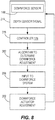
- FIG. 8 illustrates one exemplary method of controlling downforce.
- the downforce sensor 148 initially generates signals.
- the controller 178 receives the signals from the downforce sensor 148 (e.g., wirelessly or with a wired connection).
- the controller 178 uses an algorithm to determine a downforce adjustment for the row unit 118.
- the algorithm is based solely on the difference between actual and target downforce values and may perform calculations that take into account instantaneous downforce, downforce consistency, a moving average, a trend, etc.
- the algorithm additionally considers one or more additional parameters such as furrow depth, GPS location, soil moisture, soil type, speed of the seeding machine 10 through the field, etc.
- Information of this type can be measured from one or more additional sensors of the seeding machine 10 and/or the row unit 118.
- such information can be input by a human operator to the controller 178, for example from a control interface in an operator cabin.
- the controller 178 determines that there is insufficient downforce, in response through a fourth step 298 the controller 178 sends a signal to the downforce adjustment mechanism 174, and in a fifth step 302 the downforce adjustment mechanism 174 is activated and adjusts (i.e., increases) the downforce on the row unit 118.
- the increased downforce can assist in achieving a more consistent furrow depth, for example.
- the process repeats, such that the controller 178 is continuously receiving signals from the downforce sensor 148 and is continuously making adjustments to the downforce as needed (i.e., creating a closed loop). As mentioned above, this can occur simultaneously for a plurality of row units 118, each having separate downforce adjustment mechanisms 174.
- the controller 178 determines there is excess downforce at step 282, then in response through a fourth step 298 the controller 178 sends a signal to the downforce adjustment mechanism 174, and in a fifth step 302 the downforce adjustment mechanism 174 is activated and adjusts (i.e., decreases) the downforce on the row unit 118.
- the downforce control as described above can be carried out in a closed loop automated manner via the controller 178 without ongoing operator interaction.
- the measured downforce may be displayed to an operator (e.g., on a visual display), and the operator may respond by making adjustments to the downforce and/or travel speed of the seeding machine 10 as desired based on the displayed information.
Landscapes
- Life Sciences & Earth Sciences (AREA)
- Soil Sciences (AREA)
- Environmental Sciences (AREA)
- Engineering & Computer Science (AREA)
- Mechanical Engineering (AREA)
- Sowing (AREA)
- Transplanting Machines (AREA)
Abstract
Description
- The present disclosure relates to systems and methods for planting seeds, in particular with a row unit for a seeding machine.
- Various factors affect crop yields. One factor, for example, is seed depth in a furrow. Another factor is soil compaction along the furrow. A productive crop yield is typically one that grows and emerges uniformly from the soil. Understanding planting depth and soil compaction provides valuable information that may be used to generate a productive crop yield.
- In one aspect, the disclosure provides a row unit for a seeding machine operable to plant seeds into soil. The row unit includes a frame, a gauge wheel operable to engage the soil and support the frame via a gauge wheel arm connected between the gauge wheel and the frame, and a seed dispenser supported by the frame and operable to dispense seeds into the soil. The gauge wheel is supported by the frame via a gauge wheel arm. A depth stop assembly includes a stop setting an upward travel limit of the gauge wheel with respect to the frame, and a handle that is lockable and releasable to move the stop to select among a plurality of seeding depths. A downforce actuator is operable to generate a variable amount of downforce to be applied through the gauge wheel arm and the gauge wheel to the soil. A downforce sensor is incorporated into the depth stop assembly and movable therewith. The depth stop assembly includes a multi-piece body having a first piece receiving the handle, and a second piece defining a pivot joining the depth stop assembly to the frame. The first piece of the multi-piece body includes a handle-receiving receptacle portion, a fastening portion for fastening to the second piece of the multi-piece body adjacent the pivot, and a portion between the handle-receiving receptacle portion and the fastening portion forming a housing of the downforce sensor.
- In another aspect, the disclosure provides a row unit for a seeding machine operable to plant seeds into soil. The row unit includes a frame, a gauge wheel operable to engage the soil and support the frame via a gauge wheel arm connected between the gauge wheel and the frame, and a seed dispenser supported by the frame and operable to dispense seeds into the soil. The gauge wheel is supported by the frame via a gauge wheel arm. A depth stop assembly includes a stop setting an upward travel limit of the gauge wheel with respect to the frame, and a handle that is lockable and releasable to move the stop to select among a plurality of seeding depths. A pivot joins the depth stop assembly to the frame. A downforce actuator is operable to generate a variable amount of downforce to be applied through the gauge wheel arm and the gauge wheel to the soil. A downforce sensor is provided by a load cell including at least one strain gauge. The load cell is offset from the stop and positioned on an opposite side of the pivot from the stop.
- In yet another aspect, the disclosure provides a seeding row unit depth stop assembly including a stop, a handle, a and a multi-piece body. The stop presents a surface positioned to set an upward travel limit of a gauge wheel of the row unit. The handle is movable between locked and released positions, the depth stop assembly having a pivot for moving among a plurality of seeding depths when the handle is in the released position. The multi-piece body has a first piece receiving the handle, and a second piece separate from the first piece, the second piece defining the pivot. A downforce sensor is incorporated into the depth stop assembly and movable therewith. The first piece forms a housing of the downforce sensor. The downforce sensor is offset from the stop and positioned on an opposite side of the pivot from the stop.
- Other aspects of the disclosure will become apparent by consideration of the detailed description and accompanying drawings.
-
-
FIG. 1 is a perspective view of a seeding machine. -
FIG. 2 is a partially schematic side view of a row unit of the seeding machine ofFIG. 1 , including gauge wheel arms and gauge wheels. -
FIG. 3 is a perspective view of a pair of gauge wheel arms and a limiting stop of the row unit ofFIG. 2 . -
FIG. 4 is a side view of a portion of the row unit ofFIG. 2 , including a depth stop assembly with an integrated downforce sensor. -
FIG. 5 is a first perspective view of the depth stop assembly ofFIG. 4 . -
FIG. 6 is a second perspective view of the depth stop assembly ofFIGS. 4 and5 . -
FIG. 7 is a perspective view of the depth stop assembly with potting compound removed from the downforce sensor housing. -
FIG. 8 is a flowchart illustrating a process for using a downforce sensor in closed-loop downforce control. - Before embodiments of the disclosure are explained in detail, it is to be understood that the disclosure is not limited in its application to the details of construction and the arrangement of components set forth in the following description or illustrated in the accompanying drawings. The disclosure is capable of supporting other embodiments and of being practiced or of being carried out in various ways.
-
FIG. 1 illustrates a seeding machine 10 (e.g., a row crop planter). Theseeding machine 10 includes amain frame 14. A plurality ofindividual row units 18 are coupled (e.g., mounted) on a rear portion of themain frame 14, such that therow units 18 are pulled over or across a layer ofsoil 20. Alternatively, therow units 18 may be positioned forward of theframe 14 and pushed over or across thesoil layer 20, or the machine may have a combination of push andpull row units 18. Seed sources, such asstorage tanks 22a-22c, are coupled to themain frame 14 and hold seed that is delivered, e.g., pneumatically or in any other suitable manner, to a mini-hopper (not shown) associated with eachrow unit 18. Thestorage tanks 22a-22c are coupled to the mini-hoppers by way ofconduits 26, such as hoses, and a pressurized delivery apparatus (not shown). Eachstorage tank 22a-22c contains the same or different varieties of seed to be planted in thesoil 20. Eachrow unit 18 is connected to aconduit 26 such that eachrow unit 18 is coupled to astorage tank 22a-22c to receive seed. As illustrated by way of example only inFIG. 1 , eachrow unit 18 further includes itsown sub-frame 30, to which various components (e.g., a furrow opener, a furrow closer, etc.) are mounted. -
FIG. 2 illustrates an example of arow unit 118 that may be used in place of any one or more of therow units 18 inFIG. 1 . Similar to therow unit 18, therow unit 118 is also coupled to themain frame 14. In some constructions, a plurality ofrow units 118 are coupled to themain frame 14, similar to therow units 18 inFIG. 1 . As illustrated inFIG. 2 , eachrow unit 118 includeshoppers row unit 18 receiving seed from bulk storage as in the construction illustrated inFIG. 1 ). Thehoppers row unit sub-frame 130. Eachrow unit 118 also includes a gauge wheel orwheels 132 coupled to therow unit sub-frame 130. Thegauge wheel 132 contacts and rolls along thesoil 20, and a furrow opener 134 (e.g., an opening wheel or blade or other structure having a stationary or rotating surface that contacts and moves soil away to form a furrow) is coupled to therow unit sub-frame 130 for forming a furrow 136 (illustrated schematically) in thesoil 20. Aseed metering device 138 coupled to therow unit sub-frame 130 receives seeds from thehopper 122b and meters and dispenses the seeds into thefurrow 136. A furrow closer 140 (e.g., a closing and packing wheel or wheels or other structure having a stationary or rotating surface that contacts and presses soil 20) coupled to therow unit sub-frame 130 pushes soil around the seeds to close the furrow 136 (seeFIG. 1 ). Eachrow unit 118 may also include a seed firmer 144 (e.g., an angled arm as illustrated inFIG. 2 , a press wheel coupled to a press wheel arm, or other structure that firms a seed) coupled to therow unit sub-frame 130 that firms each seed and pushes it into theopen furrow 136 to ensure good seed to soil contact before thefurrow 136 is closed.FIG. 2 also illustrates an optional coulter wheel 22 and row cleaner 23 forward of thefurrow opener 134. - The
row unit 118 also includes adownforce adjustment mechanism 174 coupled to themain frame 14 and to therow unit sub-frame 130. Thedownforce adjustment mechanism 174 includes springs, pneumatics, hydraulics, linkages, and/or other structures forming an actuator such that when the downforce adjustment mechanism is activated, thedownforce adjustment mechanism 174 pushes therow unit sub-frame 130 of therow unit 118 and consequently thefurrow opener 134 into thesoil 20 to dig thefurrow 136. Thegauge wheels 132, however, continue to ride along thetop surface 158 of thesoil 20. Active downforce control can be provided by the combination of thedownforce adjustment mechanism 174, particularly the actuator thereof, along with adownforce sensor 148 and acontroller 178 as discussed in further detail herein. Adepth 154 of thefurrow 136 is measured from atop surface 158 of thesoil 20 to thebottom 162 of thefurrow 136, along a direction that is perpendicular to the top surface 158 (assuming a flat, non-inclined top surface 158), and therefore depends on a position of thegauge wheels 132 relative to thefurrow opener 134. In some constructions, thedepth 154 is equivalent to a distance between a bottom of the gauge wheel orwheels 132 and a bottom of thefurrow opener 134. Thedownforce adjustment mechanism 174 is mounted on a coupling assembly 150 that couples therow unit 118 to themain frame 14. In the example shown inFIG. 2 , a rod of the actuator forming thedownforce adjustment mechanism 174 is coupled to a link of aparallel linkage 152 and is used to exert downward force on therow unit 118 through theparallel linkage 152. - With continued reference to
FIGS. 2 and3 , the gauge wheel(s) 132 are coupled to thesub-frame 130 withrespective arms 166 andrespective pivots 170, which can be concentric as shown.Stops 186 are also provided on therow unit 118 for eachgauge wheel arm 166 to limit the upward rotation of eachgauge wheel arm 166. Thestops 186 are adjustable to a desired position to set thedepth 154 of thefurrow 136. The position of thestops 186 can be manually adjusted or a remote adjustment assembly may be included such as shown inU.S. Patent No. 4,413,685 , the entire contents of which are incorporated herein by reference. Thestops 186 form part of adepth stop assembly 190, which is shown in further detail inFIG. 4 . In particular, thestops 186 can be provided as a rocker member, which has two discrete stop surfaces for the twogauge wheel arms 166, pivotably supported on thedepth stop assembly 190 at a first or inner end thereof. At a second end opposite thestops 186, thedepth stop assembly 190 includes ahandle 194 that is lockable and releasable, e.g., invarious notches 196 on thesub-frame 130, to select among a plurality of seeding depths, each setting positioning thestops 186 at a different height with respect to thesub-frame 130. Thedepth stop assembly 190 is coupled to thesub-frame 130 with apivot 200 that allows movement among the plurality of settings when thehandle 194 is released. Thepivot 200 can be parallel to and offset from theconcentric pivots 170 of thegauge wheel arms 166. Thehandle 194 can be biased to the locked position by a biasingmember 204, such as a coil spring. - The
depth stop assembly 190, which is shown in further detail inFIGS. 5-7 , includes amulti-piece body 208 having afirst piece 2081 receiving thehandle 194, and asecond piece 2082 defining thepivot 200 joining thedepth stop assembly 190 to thesub-frame 130. The first andsecond pieces multi-piece body 208 are separate from each other and connected by respective fastening portions 2101, 2102 thereof. As illustrated, the first andsecond body pieces fasteners 212, although other fastener arrangements can be used. Within thefirst body piece 2081, there is defined a handle-receivingreceptacle portion 216, which is opposite the fastening portion 2101 as illustrated. In the illustrated construction, the handle-receivingreceptacle portion 216 is formed as a ring or loop defining anaperture 218 that receives a portion of thehandle 194. Thehandle 194 is thereby slidably received to define a handle axis A1 along which thehandle 194 is movable between its locked and released positions. Between the fastening portion 2101 and the handle-receivingreceptacle portion 216 an additional portion of thefirst body piece 2081 forms ahousing 220 of thedownforce sensor 148. - The row
unit downforce sensor 148 is one of one or more such sensors on therow unit 118 operable to sense the downforce on therow unit 118. The illustrateddownforce sensor 148 is incorporated or integrated into thedepth stop assembly 190 and movable therewith. Thedownforce sensor 148 is offset from thestops 186 and positioned on an opposite side of thepivot 200 from thestops 186. Thedownforce sensor 148 extends parallel to the handle axis A1 at a position alongside thehandle 194. Thedownforce sensor 148 can be provided as a load cell including at least onestrain gauge 224. As illustrated, thedownforce sensor 148 includes twostrain gauges 224. Each of the strain gauges 224 is oriented to measure perpendicular to the handle axis A1, along measurement direction D (both of which are perpendicular to an axis A2 of the depth stop assembly pivot 200). The strain gauges 224 can be used in combination to provide a combined output signal from the downforce sensor 148 (e.g., one strain gauge as a primary and the other as a confirmation, or alternatively measurements from the two strain gauges can be averaged). Thedownforce sensor housing 220 provided by thefirst body piece 2081 includes areceptacle 226 or recess therein (e.g., along opposite side edges thereof) for each of the strain gauges 224 so that the strain gauges 224 are set into thehousing 220 and not exposed or protruding therefrom. Thedownforce sensor 148 can also include a processor (e.g., a microprocessor) 228 coupled to the strain gauges 224 through wired or wireless connections so that signals representative of strain, and thus force or load, can be generated by thedownforce sensor 148. For example, electrical resistance changes can be monitored by theprocessor 228 onboard thedownforce sensor 148, and the electrical resistance changes can be calibrated to mechanical properties of the material forming thefirst body piece 2081. Theprocessor 228 can be provided on acircuit board 232 that is at least partially received in areceptacle 236 or recess in thehousing 220. Any or all of thereceptacles circuit board 232 can be at least partially filled with potting compound 240 that encases (e.g., molds around) the strain gauges 224 and/or thecircuit board 232, including theprocessor 228. Thedownforce sensor 148 is shown without the potting compound 240 inFIG. 7 . - As shown in
FIG. 4 , anelectrical connector 244 establishes communication between thedownforce sensor 148 and thecontroller 178. For example, theelectrical connector 244 can be a multi-pin plug-type connector and may form one half of a mating male-female junction. Theelectrical connector 244 is supported by thesecond piece 2082 of themulti-piece body 208 that defines thepivot 200 and not by thefirst piece 2081 that receives thehandle 194. For example, theelectrical connector 244 may snap into or onto thesecond piece 2082, or it may be secured with a fastener, including a threaded fastener or a strap, a clip, etc. - Referring again to
FIG. 2 , signals from thedownforce sensor 148 are sent to thecontroller 178, which tracks and/or actively manages the row unit downforce via manipulation of thedownforce adjustment mechanism 174. The controller 178 (which may include a memory and a processor for receiving and sending signals and performing calculations) uses the received signals to activate and/or adjust (i.e., increase or decrease) an output of thedownforce adjustment mechanism 174 and to thus control an overall downforce applied to therow unit 118. As discussed earlier, thedownforce sensor 148 can include an on-board processor 228, and the downforce signals can be provided to thecontroller 178 from the on-board processor 228. For example, the on-board processor 228 can perform preliminary signal conditioning of the actual measurement parameter signals (e.g., variable electrical resistance) from the strain gauges 224. This is not, however, required in all constructions, and raw measurement signals can be output from the strain gauge(s) 224 to thecontroller 178 located outside of thedownforce sensor 148. Thecontroller 178 can be dedicated to thesingular row unit 118 or may be a centralized controller of the seedingmachine 10 that receives downforce signals and manages the applied downforce of a group ofrow units 118. For example, thecontroller 178 can independently manage up to all of the row units 118 (e.g., on a plurality of separate channels, calculating and outputting separate downforce control signals) based on the independent signals from the independent rowunit downforce sensors 148 thereof. -
FIG. 8 illustrates one exemplary method of controlling downforce. In afirst step 274, thedownforce sensor 148 initially generates signals. In asecond step 278, thecontroller 178 receives the signals from the downforce sensor 148 (e.g., wirelessly or with a wired connection). In athird step 282, thecontroller 178 uses an algorithm to determine a downforce adjustment for therow unit 118. In some constructions, the algorithm is based solely on the difference between actual and target downforce values and may perform calculations that take into account instantaneous downforce, downforce consistency, a moving average, a trend, etc. In some constructions, the algorithm additionally considers one or more additional parameters such as furrow depth, GPS location, soil moisture, soil type, speed of the seedingmachine 10 through the field, etc. Information of this type can be measured from one or more additional sensors of the seedingmachine 10 and/or therow unit 118. Alternatively or additionally, such information can be input by a human operator to thecontroller 178, for example from a control interface in an operator cabin. - When the
controller 178 determines that there is insufficient downforce, in response through afourth step 298 thecontroller 178 sends a signal to thedownforce adjustment mechanism 174, and in afifth step 302 thedownforce adjustment mechanism 174 is activated and adjusts (i.e., increases) the downforce on therow unit 118. The increased downforce can assist in achieving a more consistent furrow depth, for example. As illustrated inFIG. 8 , once the downforce has been adjusted, the process repeats, such that thecontroller 178 is continuously receiving signals from thedownforce sensor 148 and is continuously making adjustments to the downforce as needed (i.e., creating a closed loop). As mentioned above, this can occur simultaneously for a plurality ofrow units 118, each having separatedownforce adjustment mechanisms 174. Alternatively, when thecontroller 178 determines there is excess downforce atstep 282, then in response through afourth step 298 thecontroller 178 sends a signal to thedownforce adjustment mechanism 174, and in afifth step 302 thedownforce adjustment mechanism 174 is activated and adjusts (i.e., decreases) the downforce on therow unit 118. - The downforce control as described above can be carried out in a closed loop automated manner via the
controller 178 without ongoing operator interaction. Alternatively, in some constructions, the measured downforce may be displayed to an operator (e.g., on a visual display), and the operator may respond by making adjustments to the downforce and/or travel speed of the seedingmachine 10 as desired based on the displayed information.
Claims (9)
- A row unit (18, 180) for a seeding machine (10) operable to plant seeds into soil, the row unit (18, 180) comprising:a frame (30, 130);a gauge wheel (132) operable to engage the soil and support the frame (30, 130) via a gauge wheel arm (166) connected between the gauge wheel (132) and the frame (30, 130);a seed dispenser supported by the frame (30, 130) and operable to dispense seeds into the soil;a depth stop assembly (190) including a stop (186) setting an upward travel limit of the gauge wheel (132) with respect to the frame (30, 130), and a handle (194) that is lockable and releasable to move the stop (186) to select among a plurality of seeding depths;a downforce adjustment mechanism (174) operable to generate a variable amount of downforce to be applied through the gauge wheel (166) and the gauge wheel (132) to the soil; anda downforce sensor (148) incorporated into the depth stop assembly (190) and movable therewith,wherein the depth stop assembly (190) includes a multi-piece body (208) having a first piece (2081) receiving the handle (194), and a second piece (2082) defining a pivot (200) joining the depth stop assembly (190) to the frame (30, 130), andwherein the first piece (2081) of the multi-piece body (208) includes a handle-receiving receptacle portion (216), a fastening portion (2102) for fastening to the second piece (2082) of the multi-piece body (208) adjacent the pivot (200), and a portion between the handle-receiving receptacle portion (216) and the fastening portion (2102) forming a housing (220) of the downforce sensor (148).
- The row unit (18, 180) of claim 1, further comprising a controller (178) programmed to output a control signal to the downforce adjustment mechanism (174) to adjust the downforce based at least partially on an output from the downforce sensor (148).
- The row unit (18, 180) of claim 2, wherein the controller (178) is programmed to control the downforce adjustment mechanism (174) to adjust a downforce on the frame (30, 130) by comparing a stored downforce target value to the output from the downforce sensor (148).
- The row unit (18, 180) of claim 2 or 3, further comprising an electrical connector (244) for establishing communication between the downforce sensor (148) and the controller (178), wherein the electrical connector (244) is supported by the second piece (2082) of the multi-piece body (208).
- The row unit (18, 180) of one of the claims 2 to 4, wherein the downforce sensor (148) is a load cell including at least one strain gauge (224) positioned in a receptacle of a downforce sensor housing (220).
- The row unit (18, 180) of one of the claims 1 to 5, wherein the stop (186) is a rocker pivotably supported on the depth stop assembly (190) and presenting two discrete stop surfaces, one of which is positioned to contact the gauge wheel (166) supporting the gauge wheel (132) and the other of which is positioned to contact a second gauge wheel (166) supporting a second gauge wheel (132).
- The row unit (18, 180) of one of the claims 1 to 6, wherein the downforce sensor (148) is offset from the stop (186) and positioned on an opposite side of the pivot (200) from the stop (186).
- The row unit (18, 180) of one of the claims 1 to 7, wherein the handle (194) is slidably received by the first piece (2081) of the multi-piece body (208) to define a handle axis, and wherein the downforce sensor (148) extends parallel to the handle axis at a position alongside the handle (194).
- The row unit (18, 180) of one of the claims 1 to 8, wherein the downforce sensor (148) is a load cell including at least one strain gauge (224) oriented to measure perpendicular to the handle axis.
Applications Claiming Priority (1)
| Application Number | Priority Date | Filing Date | Title |
|---|---|---|---|
| US16/296,951 US11134606B2 (en) | 2019-03-08 | 2019-03-08 | Planter row unit with load sensing depth stop assembly |
Publications (2)
| Publication Number | Publication Date |
|---|---|
| EP3704921A1 true EP3704921A1 (en) | 2020-09-09 |
| EP3704921B1 EP3704921B1 (en) | 2021-12-01 |
Family
ID=69845792
Family Applications (1)
| Application Number | Title | Priority Date | Filing Date |
|---|---|---|---|
| EP20158765.6A Active EP3704921B1 (en) | 2019-03-08 | 2020-02-21 | Planter row unit with load sensing depth stop assembly |
Country Status (4)
| Country | Link |
|---|---|
| US (4) | US11134606B2 (en) |
| EP (1) | EP3704921B1 (en) |
| AU (2) | AU2020200929B2 (en) |
| CA (1) | CA3071503A1 (en) |
Families Citing this family (26)
| Publication number | Priority date | Publication date | Assignee | Title |
|---|---|---|---|---|
| US11206754B2 (en) | 2018-02-21 | 2021-12-28 | Deere & Company | Depth sensing with absolute position and temperature compensation |
| US11202404B2 (en) | 2019-03-05 | 2021-12-21 | Deere & Company | Planter row unit downforce control with ground view sensor |
| US11134606B2 (en) * | 2019-03-08 | 2021-10-05 | Deere & Company | Planter row unit with load sensing depth stop assembly |
| US12029146B2 (en) | 2019-10-30 | 2024-07-09 | Deere & Company | Implement having weight transfer system and method of operating the same |
| US11589500B2 (en) | 2019-12-24 | 2023-02-28 | Cnh Industrial America Llc | Particle delivery system of an agricultural row unit |
| US11582899B2 (en) | 2019-12-24 | 2023-02-21 | Cnh Industrial America Llc | Particle delivery system of an agricultural row unit |
| US11564344B2 (en) | 2019-12-24 | 2023-01-31 | Cnh Industrial America Llc | Particle delivery system of an agricultural row unit |
| US11564346B2 (en) | 2019-12-24 | 2023-01-31 | Cnh Industrial America Llc | Particle delivery system of an agricultural row unit |
| US11483963B2 (en) | 2019-12-24 | 2022-11-01 | Cnh Industrial America Llc | Particle delivery system of an agricultural row unit |
| US11523556B2 (en) | 2019-12-24 | 2022-12-13 | Cnh Industrial America Llc | Particle delivery system of an agricultural row unit |
| US11490558B2 (en) | 2019-12-24 | 2022-11-08 | Cnh Industrial America Llc | Particle delivery system of an agricultural row unit |
| US11596095B2 (en) | 2019-12-24 | 2023-03-07 | Cnh Industrial America Llc | Particle delivery system of an agricultural row unit |
| US11553639B2 (en) | 2019-12-24 | 2023-01-17 | Cnh Industrial America Llc | Particle delivery system of an agricultural row unit |
| US11516958B2 (en) | 2019-12-24 | 2022-12-06 | Cnh Industrial America Llc | Particle delivery system of an agricultural row unit |
| US11523555B2 (en) | 2019-12-24 | 2022-12-13 | Cnh Industrial America Llc | Particle delivery system of an agricultural row unit |
| US11553638B2 (en) | 2019-12-24 | 2023-01-17 | Cnh Industrial America Llc | Particle delivery system of an agricultural row unit |
| US12185660B2 (en) * | 2020-03-17 | 2025-01-07 | Harvest International, Inc. | Adjustable depth control system for row unit planters |
| US11662245B2 (en) * | 2020-04-09 | 2023-05-30 | Caterpillar Inc. | Payload measurement system for machine with hauling body |
| US20240040958A1 (en) * | 2021-03-02 | 2024-02-08 | Precision Planting Llc | Downforce Load Sensor for a Planter Row Unit |
| DE102021122200A1 (en) | 2021-08-27 | 2023-03-02 | Horsch Maschinen Gmbh | control and/or regulation system; agricultural machine with such a system and method for operating an agricultural machine |
| CN114424699B (en) * | 2022-01-25 | 2023-03-24 | 中国科学院沈阳应用生态研究所 | Large granule fertilizer injection unit of intelligence variable |
| US12543631B2 (en) * | 2022-08-22 | 2026-02-10 | Deere & Company | Actuator for setting seed depth for a row unit on a planter |
| CN116267228A (en) * | 2023-03-14 | 2023-06-23 | 北京市农林科学院智能装备技术研究中心 | Intelligent Tea Harvesting Machine with Human-Machine Collaboration |
| WO2025065076A1 (en) * | 2023-09-25 | 2025-04-03 | Innotag Distributions Inc. | Control system and method for operating a row crop cultivator tool |
| WO2026020221A1 (en) * | 2024-07-25 | 2026-01-29 | Assy Jose Roberto Do Amaral | Stop, row unit for an agricultural planter, and downforce control system |
| CN118901351A (en) * | 2024-09-06 | 2024-11-08 | 中国农业大学 | Front-mounted seeding single depth-limiting wheel position adjusting device |
Citations (3)
| Publication number | Priority date | Publication date | Assignee | Title |
|---|---|---|---|---|
| US4413685A (en) | 1979-12-11 | 1983-11-08 | Gremelspacher Philip E | Planter implement with adjusting position-display apparatus and system thereof |
| WO2008086283A2 (en) * | 2007-01-08 | 2008-07-17 | Precision Planting Inc. | Load sensing pin |
| WO2016073964A1 (en) * | 2014-11-07 | 2016-05-12 | Dawn Equipment Company | Agricultural system |
Family Cites Families (72)
| Publication number | Priority date | Publication date | Assignee | Title |
|---|---|---|---|---|
| US2192948A (en) | 1939-03-25 | 1940-03-12 | Deere & Co | Planter |
| US4445923A (en) | 1982-12-30 | 1984-05-01 | Owens-Illinois, Inc. | Position sensing device |
| DE3430136C1 (en) | 1984-08-16 | 1986-04-24 | Amazonen-Werke H. Dreyer Gmbh & Co Kg, 4507 Hasbergen | Seed drill |
| US4915014A (en) | 1985-05-08 | 1990-04-10 | Deere & Company | Disk harrow hydraulic wing balancing system |
| US4850454A (en) | 1988-07-29 | 1989-07-25 | Allied-Signal Inc. | Disc brake lining wear sensor |
| US5201372A (en) | 1991-09-30 | 1993-04-13 | Deere & Company | Wing fold implement with hydraulic mode indicator |
| US5479992A (en) | 1993-07-27 | 1996-01-02 | Dawn Equipment Company | Agricultural implement controller to compensate for soil hardness variation |
| US5591945A (en) | 1995-04-19 | 1997-01-07 | Elo Touchsystems, Inc. | Acoustic touch position sensor using higher order horizontally polarized shear wave propagation |
| US6076611A (en) | 1998-12-17 | 2000-06-20 | Agco Corporation | Implement mounted depth control system |
| US6216794B1 (en) | 1999-07-01 | 2001-04-17 | Andrew F. Buchl | Joystick control for an automatic depth control system and method |
| US6530334B2 (en) | 2001-05-24 | 2003-03-11 | Matthew P. Hagny | Depth-limited furrow closing arrangement and method for no-till agricultural seeders |
| US6688244B1 (en) | 2002-08-08 | 2004-02-10 | Deere & Company | Product on demand delivery system |
| US7191715B2 (en) | 2004-01-16 | 2007-03-20 | Cnh America Llc | Tandem gauge wheel assembly for planting unit |
| US7360495B1 (en) | 2006-12-18 | 2008-04-22 | Howard D. Martin | Method for planter depth monitoring |
| US7673570B1 (en) | 2008-12-01 | 2010-03-09 | Dawn Equipment Company | Row-clearing unit for agricultural implement |
| US8326500B2 (en) | 2009-11-17 | 2012-12-04 | Deere & Company | Row unit wheel turning monitor for an agricultural machine |
| US9968030B2 (en) | 2010-06-22 | 2018-05-15 | Cnh Industrial Canada, Ltd. | Down pressure adjustment device and method for use with a disc opener assembly of an agricultural implement |
| US8522889B2 (en) | 2010-08-30 | 2013-09-03 | Cnh America Llc | Agricultural implement with combined down force and depth control |
| US8544397B2 (en) | 2010-09-15 | 2013-10-01 | Dawn Equipment Company | Row unit for agricultural implement |
| US9232687B2 (en) * | 2010-09-15 | 2016-01-12 | Dawn Equipment Company | Agricultural systems |
| US9107337B2 (en) | 2012-08-20 | 2015-08-18 | Dawn Equipment Company | Agricultural apparatus for sensing and providing feedback of soil property changes in real time |
| US8634992B2 (en) | 2011-01-26 | 2014-01-21 | Precision Planting Llc | Dynamic supplemental downforce control system for planter row units |
| US9743578B2 (en) | 2011-04-27 | 2017-08-29 | Kinze Manufacturing, Inc. | Agricultural devices, systems, and methods for determining soil and seed characteristics and analyzing the same |
| RU2576457C2 (en) | 2011-04-27 | 2016-03-10 | Кинз Мэньюфэкчеринг, Инк. | System regulating force directed downward and/or upward |
| US8380356B1 (en) | 2012-06-12 | 2013-02-19 | Ag Leader Technology | Seeder downforce section control |
| US8863676B2 (en) | 2012-07-12 | 2014-10-21 | Deere & Company | Twin-row multiple variety planter and method of use |
| CA3183433A1 (en) | 2012-07-25 | 2014-01-30 | Precision Planting Llc | Integrated implement downforce control systems, methods, and apparatus |
| EP3259972B1 (en) | 2012-07-25 | 2021-12-08 | Precision Planting LLC | System and method for multi-row agricultural implement control and monitoring |
| CA2880570C (en) | 2012-08-10 | 2023-01-03 | Precision Planting Llc | Monitoring and mapping of agricultural applications |
| US9683841B2 (en) | 2012-09-07 | 2017-06-20 | Apple Inc. | Imaging range finder fabrication |
| US20140076047A1 (en) | 2012-09-14 | 2014-03-20 | James Z. Liu | Tank commidity volume measurement apparatus and method |
| UA125643C2 (en) | 2012-10-24 | 2022-05-11 | Пресіжн Плентінг Елелсі | Agricultural systems, methods and device for measuring the depth of furrow |
| AU2013334548B2 (en) | 2012-10-24 | 2017-10-26 | Precision Planting Llc | Agricultural trench closing systems, methods, and apparatus |
| US9629304B2 (en) | 2013-04-08 | 2017-04-25 | Ag Leader Technology | On-the go soil sensors and control methods for agricultural machines |
| US20160101426A1 (en) | 2013-05-21 | 2016-04-14 | Flsmidth A/S | Methods and apparatus for the continuous monitoring of wear in grinding circuits |
| US9198343B2 (en) | 2013-07-12 | 2015-12-01 | Deere & Company | Implement weight transfer with feedback control |
| EP3065526B1 (en) | 2013-11-08 | 2020-09-02 | Precision Planting LLC | Implement weight management systems, methods, and apparatus |
| US10285323B2 (en) | 2013-11-13 | 2019-05-14 | Cnh Industrial America Llc | Agricultural tillage implement fold sequence control |
| US9554504B2 (en) | 2014-02-19 | 2017-01-31 | Shane Houck | Depth control for a seed planting system |
| EP3107367B1 (en) | 2014-02-21 | 2023-08-02 | Blue River Technology Inc. | Method and system for in-situ precision calibration of a precision agricultural system to accommodate for a treatment delay |
| US9723778B2 (en) | 2014-11-07 | 2017-08-08 | Dawn Equipment Company | Agricultural system |
| US10582653B2 (en) | 2014-11-07 | 2020-03-10 | Dawn Equipment Company | Agricultural planting system with automatic depth control |
| US9826677B2 (en) | 2014-12-16 | 2017-11-28 | Cnh Industrial Canada, Ltd. | Seed implement incorporating a down pressure sensing and adjustment system |
| US9482301B2 (en) | 2015-03-25 | 2016-11-01 | Honeywell International Inc. | Brake disc stack wear measurement |
| US10262413B2 (en) | 2015-05-08 | 2019-04-16 | The Climate Corporation | Work layer imaging and analysis for implement monitoring, control and operator feedback |
| US10180076B2 (en) | 2015-06-01 | 2019-01-15 | Hamilton Sundstrand Corporation | Redundant speed summing actuators |
| US9888624B2 (en) | 2015-06-30 | 2018-02-13 | Cnh Industrial America Llc | Individual row lift system for planters |
| US9693496B2 (en) | 2015-09-30 | 2017-07-04 | Deere & Company | Agricultural planting depth sensor |
| US9839178B2 (en) | 2015-09-30 | 2017-12-12 | Deere & Company | Seed firmer |
| US9848527B2 (en) | 2015-09-30 | 2017-12-26 | Deere & Company | Furrow following device |
| US9883626B2 (en) | 2015-10-02 | 2018-02-06 | Deere & Company | Controlling an agricultural vehicle based on sensed inputs |
| NL2015744B1 (en) | 2015-11-06 | 2017-05-24 | Vredo Beheer B V | Method, tool, and system for introducing manure into the soil. |
| US10462956B2 (en) | 2016-06-28 | 2019-11-05 | Agco Corporation | Down force control to allow for easier depth adjustment |
| US10091926B2 (en) | 2016-08-12 | 2018-10-09 | Deere & Company | Downforce sensing and control with acceleration correction |
| US10694658B2 (en) | 2016-09-30 | 2020-06-30 | Deere & Company | Planter row unit furrow depth sensing apparatus and method |
| US9936631B1 (en) | 2016-09-30 | 2018-04-10 | Deere & Company | Device and method for detecting and reporting seed placement |
| US10918012B2 (en) | 2016-09-30 | 2021-02-16 | Deere & Company | Planter row unit furrow depth sensing apparatus and method |
| US10681859B2 (en) | 2016-09-30 | 2020-06-16 | Deere & Company | Planter row unit furrow depth sensing apparatus and method |
| US10555454B2 (en) | 2016-09-30 | 2020-02-11 | Deere & Company | Planter row unit furrow depth sensing apparatus and method |
| US10687456B2 (en) | 2016-09-30 | 2020-06-23 | Deere & Company | Planter row unit furrow depth sensing apparatus and method |
| US10687457B2 (en) | 2016-09-30 | 2020-06-23 | Deere & Company | Planter row unit furrow depth sensing apparatus and method |
| US10197378B2 (en) | 2016-10-27 | 2019-02-05 | Deere & Company | Time domain depth sensor |
| US10928504B2 (en) | 2017-01-31 | 2021-02-23 | Kinze Manufactoring, Inc. | Radar based seed sensor for use with agricultural systems, methods, and apparatus |
| US11122731B2 (en) | 2017-10-31 | 2021-09-21 | Deere & Company | Method of managing planter row unit downforce |
| BR122022021326B1 (en) | 2017-11-15 | 2023-11-28 | Precision Planting Llc | SYSTEM FOR DETECTING CHARACTERISTICS OF A TRENCH IN A GROUND SURFACE DURING PLANTING OPERATIONS |
| US11140812B2 (en) | 2017-12-15 | 2021-10-12 | Kinze Manufacturing, Inc. | Systems, methods, and apparatus for controlling downforce of an agricultural implement |
| US11206754B2 (en) | 2018-02-21 | 2021-12-28 | Deere & Company | Depth sensing with absolute position and temperature compensation |
| US11202404B2 (en) | 2019-03-05 | 2021-12-21 | Deere & Company | Planter row unit downforce control with ground view sensor |
| US11134606B2 (en) * | 2019-03-08 | 2021-10-05 | Deere & Company | Planter row unit with load sensing depth stop assembly |
| US12029146B2 (en) | 2019-10-30 | 2024-07-09 | Deere & Company | Implement having weight transfer system and method of operating the same |
| US11279366B1 (en) | 2020-11-17 | 2022-03-22 | Deere & Company | Feedforward mechanism with signal decay for torque adjustment in diesel engine operation |
| US12256946B2 (en) | 2020-11-30 | 2025-03-25 | Timothy Tian Roberts | Surgical rongeur and methods thereof |
-
2019
- 2019-03-08 US US16/296,951 patent/US11134606B2/en active Active
-
2020
- 2020-02-06 CA CA3071503A patent/CA3071503A1/en active Pending
- 2020-02-10 AU AU2020200929A patent/AU2020200929B2/en active Active
- 2020-02-21 EP EP20158765.6A patent/EP3704921B1/en active Active
-
2021
- 2021-10-04 US US17/493,423 patent/US11925137B2/en active Active
-
2024
- 2024-02-12 US US18/439,379 patent/US20240298567A1/en not_active Abandoned
-
2025
- 2025-06-06 US US19/230,220 patent/US20260107871A1/en active Pending
- 2025-08-01 AU AU2025210867A patent/AU2025210867A1/en active Pending
Patent Citations (3)
| Publication number | Priority date | Publication date | Assignee | Title |
|---|---|---|---|---|
| US4413685A (en) | 1979-12-11 | 1983-11-08 | Gremelspacher Philip E | Planter implement with adjusting position-display apparatus and system thereof |
| WO2008086283A2 (en) * | 2007-01-08 | 2008-07-17 | Precision Planting Inc. | Load sensing pin |
| WO2016073964A1 (en) * | 2014-11-07 | 2016-05-12 | Dawn Equipment Company | Agricultural system |
Also Published As
| Publication number | Publication date |
|---|---|
| US20260107871A1 (en) | 2026-04-23 |
| US11134606B2 (en) | 2021-10-05 |
| US20240298567A1 (en) | 2024-09-12 |
| US20220022366A1 (en) | 2022-01-27 |
| EP3704921B1 (en) | 2021-12-01 |
| AU2020200929B2 (en) | 2025-08-28 |
| AU2025210867A1 (en) | 2025-08-21 |
| US20200281112A1 (en) | 2020-09-10 |
| US11925137B2 (en) | 2024-03-12 |
| CA3071503A1 (en) | 2020-09-08 |
| BR102020002396A2 (en) | 2020-09-29 |
| AU2020200929A1 (en) | 2020-09-24 |
Similar Documents
| Publication | Publication Date | Title |
|---|---|---|
| US11925137B2 (en) | Planter row unit with load sensing depth stop assembly | |
| RU2600182C2 (en) | Bulk handling system for seed sowing machines and machines for products input | |
| US9198343B2 (en) | Implement weight transfer with feedback control | |
| US8910582B2 (en) | Row unit for a seeding machine having active downforce control for the closing wheels | |
| US9338937B2 (en) | Load sensing pin | |
| EP3704926A1 (en) | Row unit | |
| EP2701482B1 (en) | Down and/or up force adjustment system | |
| US10219427B2 (en) | Independent closing system with adjustable down force | |
| EP3150044A1 (en) | Seeding machine | |
| EP3815503B1 (en) | Implement having weight transfer system | |
| EP4268564B1 (en) | Agricultural machine and method of automatically redistributing weight across a frame of such | |
| BR102020002396B1 (en) | Row unit for a seeding machine. | |
| US12457920B2 (en) | Intermediate tanks for frame weight distribution | |
| CA3206036A1 (en) | Intermediate tanks for frame weight distribution | |
| AU2023208164A1 (en) | Intermediate tanks for frame weight distribution |
Legal Events
| Date | Code | Title | Description |
|---|---|---|---|
| PUAI | Public reference made under article 153(3) epc to a published international application that has entered the european phase |
Free format text: ORIGINAL CODE: 0009012 |
|
| STAA | Information on the status of an ep patent application or granted ep patent |
Free format text: STATUS: THE APPLICATION HAS BEEN PUBLISHED |
|
| AK | Designated contracting states |
Kind code of ref document: A1 Designated state(s): AL AT BE BG CH CY CZ DE DK EE ES FI FR GB GR HR HU IE IS IT LI LT LU LV MC MK MT NL NO PL PT RO RS SE SI SK SM TR |
|
| AX | Request for extension of the european patent |
Extension state: BA ME |
|
| STAA | Information on the status of an ep patent application or granted ep patent |
Free format text: STATUS: REQUEST FOR EXAMINATION WAS MADE |
|
| 17P | Request for examination filed |
Effective date: 20210309 |
|
| RBV | Designated contracting states (corrected) |
Designated state(s): AL AT BE BG CH CY CZ DE DK EE ES FI FR GB GR HR HU IE IS IT LI LT LU LV MC MK MT NL NO PL PT RO RS SE SI SK SM TR |
|
| GRAP | Despatch of communication of intention to grant a patent |
Free format text: ORIGINAL CODE: EPIDOSNIGR1 |
|
| STAA | Information on the status of an ep patent application or granted ep patent |
Free format text: STATUS: GRANT OF PATENT IS INTENDED |
|
| INTG | Intention to grant announced |
Effective date: 20210714 |
|
| GRAS | Grant fee paid |
Free format text: ORIGINAL CODE: EPIDOSNIGR3 |
|
| GRAA | (expected) grant |
Free format text: ORIGINAL CODE: 0009210 |
|
| STAA | Information on the status of an ep patent application or granted ep patent |
Free format text: STATUS: THE PATENT HAS BEEN GRANTED |
|
| AK | Designated contracting states |
Kind code of ref document: B1 Designated state(s): AL AT BE BG CH CY CZ DE DK EE ES FI FR GB GR HR HU IE IS IT LI LT LU LV MC MK MT NL NO PL PT RO RS SE SI SK SM TR |
|
| REG | Reference to a national code |
Ref country code: GB Ref legal event code: FG4D |
|
| REG | Reference to a national code |
Ref country code: AT Ref legal event code: REF Ref document number: 1450884 Country of ref document: AT Kind code of ref document: T Effective date: 20211215 Ref country code: CH Ref legal event code: EP |
|
| REG | Reference to a national code |
Ref country code: IE Ref legal event code: FG4D |
|
| REG | Reference to a national code |
Ref country code: DE Ref legal event code: R096 Ref document number: 602020001127 Country of ref document: DE |
|
| REG | Reference to a national code |
Ref country code: LT Ref legal event code: MG9D |
|
| REG | Reference to a national code |
Ref country code: NL Ref legal event code: MP Effective date: 20211201 |
|
| REG | Reference to a national code |
Ref country code: AT Ref legal event code: MK05 Ref document number: 1450884 Country of ref document: AT Kind code of ref document: T Effective date: 20211201 |
|
| PG25 | Lapsed in a contracting state [announced via postgrant information from national office to epo] |
Ref country code: RS Free format text: LAPSE BECAUSE OF FAILURE TO SUBMIT A TRANSLATION OF THE DESCRIPTION OR TO PAY THE FEE WITHIN THE PRESCRIBED TIME-LIMIT Effective date: 20211201 Ref country code: LT Free format text: LAPSE BECAUSE OF FAILURE TO SUBMIT A TRANSLATION OF THE DESCRIPTION OR TO PAY THE FEE WITHIN THE PRESCRIBED TIME-LIMIT Effective date: 20211201 Ref country code: FI Free format text: LAPSE BECAUSE OF FAILURE TO SUBMIT A TRANSLATION OF THE DESCRIPTION OR TO PAY THE FEE WITHIN THE PRESCRIBED TIME-LIMIT Effective date: 20211201 Ref country code: BG Free format text: LAPSE BECAUSE OF FAILURE TO SUBMIT A TRANSLATION OF THE DESCRIPTION OR TO PAY THE FEE WITHIN THE PRESCRIBED TIME-LIMIT Effective date: 20220301 Ref country code: AT Free format text: LAPSE BECAUSE OF FAILURE TO SUBMIT A TRANSLATION OF THE DESCRIPTION OR TO PAY THE FEE WITHIN THE PRESCRIBED TIME-LIMIT Effective date: 20211201 |
|
| PG25 | Lapsed in a contracting state [announced via postgrant information from national office to epo] |
Ref country code: SE Free format text: LAPSE BECAUSE OF FAILURE TO SUBMIT A TRANSLATION OF THE DESCRIPTION OR TO PAY THE FEE WITHIN THE PRESCRIBED TIME-LIMIT Effective date: 20211201 Ref country code: PL Free format text: LAPSE BECAUSE OF FAILURE TO SUBMIT A TRANSLATION OF THE DESCRIPTION OR TO PAY THE FEE WITHIN THE PRESCRIBED TIME-LIMIT Effective date: 20211201 Ref country code: NO Free format text: LAPSE BECAUSE OF FAILURE TO SUBMIT A TRANSLATION OF THE DESCRIPTION OR TO PAY THE FEE WITHIN THE PRESCRIBED TIME-LIMIT Effective date: 20220301 Ref country code: LV Free format text: LAPSE BECAUSE OF FAILURE TO SUBMIT A TRANSLATION OF THE DESCRIPTION OR TO PAY THE FEE WITHIN THE PRESCRIBED TIME-LIMIT Effective date: 20211201 Ref country code: HR Free format text: LAPSE BECAUSE OF FAILURE TO SUBMIT A TRANSLATION OF THE DESCRIPTION OR TO PAY THE FEE WITHIN THE PRESCRIBED TIME-LIMIT Effective date: 20211201 Ref country code: GR Free format text: LAPSE BECAUSE OF FAILURE TO SUBMIT A TRANSLATION OF THE DESCRIPTION OR TO PAY THE FEE WITHIN THE PRESCRIBED TIME-LIMIT Effective date: 20220302 |
|
| PG25 | Lapsed in a contracting state [announced via postgrant information from national office to epo] |
Ref country code: NL Free format text: LAPSE BECAUSE OF FAILURE TO SUBMIT A TRANSLATION OF THE DESCRIPTION OR TO PAY THE FEE WITHIN THE PRESCRIBED TIME-LIMIT Effective date: 20211201 |
|
| PG25 | Lapsed in a contracting state [announced via postgrant information from national office to epo] |
Ref country code: SM Free format text: LAPSE BECAUSE OF FAILURE TO SUBMIT A TRANSLATION OF THE DESCRIPTION OR TO PAY THE FEE WITHIN THE PRESCRIBED TIME-LIMIT Effective date: 20211201 Ref country code: SK Free format text: LAPSE BECAUSE OF FAILURE TO SUBMIT A TRANSLATION OF THE DESCRIPTION OR TO PAY THE FEE WITHIN THE PRESCRIBED TIME-LIMIT Effective date: 20211201 Ref country code: RO Free format text: LAPSE BECAUSE OF FAILURE TO SUBMIT A TRANSLATION OF THE DESCRIPTION OR TO PAY THE FEE WITHIN THE PRESCRIBED TIME-LIMIT Effective date: 20211201 Ref country code: PT Free format text: LAPSE BECAUSE OF FAILURE TO SUBMIT A TRANSLATION OF THE DESCRIPTION OR TO PAY THE FEE WITHIN THE PRESCRIBED TIME-LIMIT Effective date: 20220401 Ref country code: ES Free format text: LAPSE BECAUSE OF FAILURE TO SUBMIT A TRANSLATION OF THE DESCRIPTION OR TO PAY THE FEE WITHIN THE PRESCRIBED TIME-LIMIT Effective date: 20211201 Ref country code: EE Free format text: LAPSE BECAUSE OF FAILURE TO SUBMIT A TRANSLATION OF THE DESCRIPTION OR TO PAY THE FEE WITHIN THE PRESCRIBED TIME-LIMIT Effective date: 20211201 Ref country code: CZ Free format text: LAPSE BECAUSE OF FAILURE TO SUBMIT A TRANSLATION OF THE DESCRIPTION OR TO PAY THE FEE WITHIN THE PRESCRIBED TIME-LIMIT Effective date: 20211201 |
|
| REG | Reference to a national code |
Ref country code: DE Ref legal event code: R097 Ref document number: 602020001127 Country of ref document: DE |
|
| PG25 | Lapsed in a contracting state [announced via postgrant information from national office to epo] |
Ref country code: MC Free format text: LAPSE BECAUSE OF FAILURE TO SUBMIT A TRANSLATION OF THE DESCRIPTION OR TO PAY THE FEE WITHIN THE PRESCRIBED TIME-LIMIT Effective date: 20211201 Ref country code: IS Free format text: LAPSE BECAUSE OF FAILURE TO SUBMIT A TRANSLATION OF THE DESCRIPTION OR TO PAY THE FEE WITHIN THE PRESCRIBED TIME-LIMIT Effective date: 20220401 |
|
| PLBE | No opposition filed within time limit |
Free format text: ORIGINAL CODE: 0009261 |
|
| STAA | Information on the status of an ep patent application or granted ep patent |
Free format text: STATUS: NO OPPOSITION FILED WITHIN TIME LIMIT |
|
| REG | Reference to a national code |
Ref country code: BE Ref legal event code: MM Effective date: 20220228 |
|
| PG25 | Lapsed in a contracting state [announced via postgrant information from national office to epo] |
Ref country code: LU Free format text: LAPSE BECAUSE OF NON-PAYMENT OF DUE FEES Effective date: 20220221 Ref country code: DK Free format text: LAPSE BECAUSE OF FAILURE TO SUBMIT A TRANSLATION OF THE DESCRIPTION OR TO PAY THE FEE WITHIN THE PRESCRIBED TIME-LIMIT Effective date: 20211201 Ref country code: AL Free format text: LAPSE BECAUSE OF FAILURE TO SUBMIT A TRANSLATION OF THE DESCRIPTION OR TO PAY THE FEE WITHIN THE PRESCRIBED TIME-LIMIT Effective date: 20211201 |
|
| 26N | No opposition filed |
Effective date: 20220902 |
|
| PG25 | Lapsed in a contracting state [announced via postgrant information from national office to epo] |
Ref country code: SI Free format text: LAPSE BECAUSE OF FAILURE TO SUBMIT A TRANSLATION OF THE DESCRIPTION OR TO PAY THE FEE WITHIN THE PRESCRIBED TIME-LIMIT Effective date: 20211201 |
|
| PG25 | Lapsed in a contracting state [announced via postgrant information from national office to epo] |
Ref country code: IE Free format text: LAPSE BECAUSE OF NON-PAYMENT OF DUE FEES Effective date: 20220221 |
|
| PG25 | Lapsed in a contracting state [announced via postgrant information from national office to epo] |
Ref country code: BE Free format text: LAPSE BECAUSE OF NON-PAYMENT OF DUE FEES Effective date: 20220228 |
|
| PG25 | Lapsed in a contracting state [announced via postgrant information from national office to epo] |
Ref country code: IT Free format text: LAPSE BECAUSE OF FAILURE TO SUBMIT A TRANSLATION OF THE DESCRIPTION OR TO PAY THE FEE WITHIN THE PRESCRIBED TIME-LIMIT Effective date: 20211201 |
|
| REG | Reference to a national code |
Ref country code: CH Ref legal event code: PL |
|
| PG25 | Lapsed in a contracting state [announced via postgrant information from national office to epo] |
Ref country code: LI Free format text: LAPSE BECAUSE OF NON-PAYMENT OF DUE FEES Effective date: 20230228 Ref country code: CH Free format text: LAPSE BECAUSE OF NON-PAYMENT OF DUE FEES Effective date: 20230228 |
|
| PG25 | Lapsed in a contracting state [announced via postgrant information from national office to epo] |
Ref country code: MK Free format text: LAPSE BECAUSE OF FAILURE TO SUBMIT A TRANSLATION OF THE DESCRIPTION OR TO PAY THE FEE WITHIN THE PRESCRIBED TIME-LIMIT Effective date: 20211201 Ref country code: CY Free format text: LAPSE BECAUSE OF FAILURE TO SUBMIT A TRANSLATION OF THE DESCRIPTION OR TO PAY THE FEE WITHIN THE PRESCRIBED TIME-LIMIT Effective date: 20211201 |
|
| PG25 | Lapsed in a contracting state [announced via postgrant information from national office to epo] |
Ref country code: HU Free format text: LAPSE BECAUSE OF FAILURE TO SUBMIT A TRANSLATION OF THE DESCRIPTION OR TO PAY THE FEE WITHIN THE PRESCRIBED TIME-LIMIT; INVALID AB INITIO Effective date: 20200221 |
|
| PG25 | Lapsed in a contracting state [announced via postgrant information from national office to epo] |
Ref country code: TR Free format text: LAPSE BECAUSE OF FAILURE TO SUBMIT A TRANSLATION OF THE DESCRIPTION OR TO PAY THE FEE WITHIN THE PRESCRIBED TIME-LIMIT Effective date: 20211201 |
|
| PG25 | Lapsed in a contracting state [announced via postgrant information from national office to epo] |
Ref country code: MT Free format text: LAPSE BECAUSE OF FAILURE TO SUBMIT A TRANSLATION OF THE DESCRIPTION OR TO PAY THE FEE WITHIN THE PRESCRIBED TIME-LIMIT Effective date: 20211201 |
|
| GBPC | Gb: european patent ceased through non-payment of renewal fee |
Effective date: 20240221 |
|
| PG25 | Lapsed in a contracting state [announced via postgrant information from national office to epo] |
Ref country code: GB Free format text: LAPSE BECAUSE OF NON-PAYMENT OF DUE FEES Effective date: 20240221 |
|
| PG25 | Lapsed in a contracting state [announced via postgrant information from national office to epo] |
Ref country code: GB Free format text: LAPSE BECAUSE OF NON-PAYMENT OF DUE FEES Effective date: 20240221 |
|
| PGFP | Annual fee paid to national office [announced via postgrant information from national office to epo] |
Ref country code: DE Payment date: 20260121 Year of fee payment: 7 |
|
| PGFP | Annual fee paid to national office [announced via postgrant information from national office to epo] |
Ref country code: FR Payment date: 20260225 Year of fee payment: 7 |