EP3704883B1 - Method for managing ue context and device supporting the same - Google Patents
Method for managing ue context and device supporting the same Download PDFInfo
- Publication number
- EP3704883B1 EP3704883B1 EP18875583.9A EP18875583A EP3704883B1 EP 3704883 B1 EP3704883 B1 EP 3704883B1 EP 18875583 A EP18875583 A EP 18875583A EP 3704883 B1 EP3704883 B1 EP 3704883B1
- Authority
- EP
- European Patent Office
- Prior art keywords
- rrc
- context
- gnb
- message
- base station
- Prior art date
- Legal status (The legal status is an assumption and is not a legal conclusion. Google has not performed a legal analysis and makes no representation as to the accuracy of the status listed.)
- Active
Links
- 238000000034 method Methods 0.000 title claims description 66
- 230000004044 response Effects 0.000 claims description 38
- 238000012546 transfer Methods 0.000 claims description 25
- 238000004891 communication Methods 0.000 claims description 23
- 230000005540 biological transmission Effects 0.000 claims description 13
- 230000011664 signaling Effects 0.000 claims description 8
- 108091005487 SCARB1 Proteins 0.000 claims description 4
- 102100037118 Scavenger receptor class B member 1 Human genes 0.000 claims description 4
- 101100150273 Caenorhabditis elegans srb-1 gene Proteins 0.000 claims description 3
- 230000006870 function Effects 0.000 description 33
- 230000000737 periodic effect Effects 0.000 description 30
- 230000015654 memory Effects 0.000 description 21
- 238000007726 management method Methods 0.000 description 17
- 238000010586 diagram Methods 0.000 description 7
- 238000012545 processing Methods 0.000 description 4
- 230000007704 transition Effects 0.000 description 4
- 238000013507 mapping Methods 0.000 description 3
- 238000005259 measurement Methods 0.000 description 3
- 230000008520 organization Effects 0.000 description 3
- 230000008569 process Effects 0.000 description 3
- 238000013468 resource allocation Methods 0.000 description 3
- 230000001960 triggered effect Effects 0.000 description 3
- 238000004873 anchoring Methods 0.000 description 2
- 238000012937 correction Methods 0.000 description 2
- 238000005516 engineering process Methods 0.000 description 2
- VJYFKVYYMZPMAB-UHFFFAOYSA-N ethoprophos Chemical compound CCCSP(=O)(OCC)SCCC VJYFKVYYMZPMAB-UHFFFAOYSA-N 0.000 description 2
- 238000012423 maintenance Methods 0.000 description 2
- 230000011218 segmentation Effects 0.000 description 2
- 101150014328 RAN2 gene Proteins 0.000 description 1
- 101150074586 RAN3 gene Proteins 0.000 description 1
- 230000006978 adaptation Effects 0.000 description 1
- 230000008859 change Effects 0.000 description 1
- 230000006835 compression Effects 0.000 description 1
- 238000007906 compression Methods 0.000 description 1
- 230000006837 decompression Effects 0.000 description 1
- 238000001514 detection method Methods 0.000 description 1
- 230000000694 effects Effects 0.000 description 1
- 238000001914 filtration Methods 0.000 description 1
- 230000007774 longterm Effects 0.000 description 1
- 238000010295 mobile communication Methods 0.000 description 1
- 238000012986 modification Methods 0.000 description 1
- 230000004048 modification Effects 0.000 description 1
- 238000012913 prioritisation Methods 0.000 description 1
Images


Classifications
-
- H—ELECTRICITY
- H04—ELECTRIC COMMUNICATION TECHNIQUE
- H04W—WIRELESS COMMUNICATION NETWORKS
- H04W48/00—Access restriction; Network selection; Access point selection
- H04W48/20—Selecting an access point
-
- H—ELECTRICITY
- H04—ELECTRIC COMMUNICATION TECHNIQUE
- H04W—WIRELESS COMMUNICATION NETWORKS
- H04W36/00—Hand-off or reselection arrangements
- H04W36/0005—Control or signalling for completing the hand-off
- H04W36/0011—Control or signalling for completing the hand-off for data sessions of end-to-end connection
- H04W36/0033—Control or signalling for completing the hand-off for data sessions of end-to-end connection with transfer of context information
-
- H—ELECTRICITY
- H04—ELECTRIC COMMUNICATION TECHNIQUE
- H04L—TRANSMISSION OF DIGITAL INFORMATION, e.g. TELEGRAPHIC COMMUNICATION
- H04L1/00—Arrangements for detecting or preventing errors in the information received
- H04L1/12—Arrangements for detecting or preventing errors in the information received by using return channel
- H04L1/16—Arrangements for detecting or preventing errors in the information received by using return channel in which the return channel carries supervisory signals, e.g. repetition request signals
- H04L1/1607—Details of the supervisory signal
- H04L1/1664—Details of the supervisory signal the supervisory signal being transmitted together with payload signals; piggybacking
-
- H—ELECTRICITY
- H04—ELECTRIC COMMUNICATION TECHNIQUE
- H04W—WIRELESS COMMUNICATION NETWORKS
- H04W36/00—Hand-off or reselection arrangements
- H04W36/08—Reselecting an access point
-
- H—ELECTRICITY
- H04—ELECTRIC COMMUNICATION TECHNIQUE
- H04W—WIRELESS COMMUNICATION NETWORKS
- H04W68/00—User notification, e.g. alerting and paging, for incoming communication, change of service or the like
- H04W68/005—Transmission of information for alerting of incoming communication
-
- H—ELECTRICITY
- H04—ELECTRIC COMMUNICATION TECHNIQUE
- H04W—WIRELESS COMMUNICATION NETWORKS
- H04W60/00—Affiliation to network, e.g. registration; Terminating affiliation with the network, e.g. de-registration
- H04W60/04—Affiliation to network, e.g. registration; Terminating affiliation with the network, e.g. de-registration using triggered events
-
- H—ELECTRICITY
- H04—ELECTRIC COMMUNICATION TECHNIQUE
- H04W—WIRELESS COMMUNICATION NETWORKS
- H04W60/00—Affiliation to network, e.g. registration; Terminating affiliation with the network, e.g. de-registration
- H04W60/06—De-registration or detaching
-
- H—ELECTRICITY
- H04—ELECTRIC COMMUNICATION TECHNIQUE
- H04W—WIRELESS COMMUNICATION NETWORKS
- H04W76/00—Connection management
- H04W76/20—Manipulation of established connections
- H04W76/27—Transitions between radio resource control [RRC] states
Landscapes
- Engineering & Computer Science (AREA)
- Computer Networks & Wireless Communication (AREA)
- Signal Processing (AREA)
- Computer Security & Cryptography (AREA)
- Mobile Radio Communication Systems (AREA)
Description
- The present invention relates to a wireless communication system, and more particularly, to a method for managing UE context performed by a first base station and second base station, and a device supporting the same.
- Efforts have been made to develop an improved 5th-generation (5G) communication system or a pre-5G communication system in order to satisfy a growing demand on radio data traffic after commercialization of a 4th-generation (4G) communication system. A standardization act for a 5G mobile communication standard work has been formally started in 3GPP, and there is ongoing discussion in a standardization working group under a tentative name of a new radio access (NR).
- Meanwhile, an upper layer protocol defines a protocol state to consistently manage an operational state of a user equipment (UE), and indicates a function and procedure of the UE in detail. In the discussion on the NR standardization, an RRC state is discussed such that an RRC_CONNECTED state and an RRC_IDLE state are basically defined, and an RRC_INACTIVE state is additionally introduced.
- Meanwhile, there will be a problem when UE notifies the network that it is still reachable in the RAN-based notification area by using the periodic RAN-based notification area update (RNAU). The UE transits from the RRC-INACTIVE state to the RRC-CONNECTED state to perform the RNAU. Whenever the UE enters to the RRC-CONNECTED state, the new gNB should fetch the UE context from the anchor gNB. However, after the periodic RNAU, the UE returns into the RRC-INACTIVE state and moves within the configured RAN-based notification area. This means that the transfer for the UE context may be repeated whenever the RNAU is triggered. Document: HUAWEI ET AL, "RAN-based notification area update", vol. RAN WG3, no. Prague, Czech Republic; 20171009 - 20171013, (20171009), 3GPP DRAFT; R3-173706, 3RD GENERATION PARTNERSHIP PROJECT (3GPP), MOBILE COMPETENCE CENTRE ; 650, ROUTE DES LUCIOLES ; F-06921 SOPHIA-ANTIPOLIS CEDEX ; FRANCE, URL: http://www.3gpp.org/ftp/Meetings_3GPP_SYNC/RAN3/Docs/, (20171009), relates to RAN-based notification area update in 3GPP. Document: ZTE CORPORATION ET AL, "Considertion on periodic RAN area update procedure", vol. RAN WG2, no. Prague, Czech Republic; 20171009 - 20171013, (20171008), 3GPP DRAFT; R2-1710429 CONSIDERATION ON PERIODIC RAN AREA UPDATE PROCEDURE, 3RD GENERATION PARTNERSHIP PROJECT (3GPP), MOBILE COMPETENCE CENTRE ; 650, ROUTE DES LUCIOLES ; F-06921 SOPHIA-ANTIPOLIS CED, URL: http://www.3gpp.org/ftp/Meetings_3GPP_SYNC/RAN2/Docs/, (20171008), relates to RAN update procedures in 3GPP.
- According to a prior art, whenever the LTE accesses to the gNB to notify the network that it is still reachable in the RAN-based notification area, the UE context should be fetched from the last serving gNB to the new gNB. It may cause the unnecessary signalling and additional latency, even when no data transmission between the UE and gNB may be occurred during the RNAU.
- According to an aspect of present invention, a method according to claim 1 is provided.
- The first BS may be last serving base station, and the second BS may be a current serving base station.
- According to another aspect of the present invention, a first base station according to claim 4 is provided.
- The first BS may be last serving base station, and the second BS may be a current serving base station.
- According to an example useful for understanding of the present invention, a method performed by a second base station (BS) in a wireless communication system is provided. The method may comprise: receiving a radio resource control (RRC) resume request message including a RRC establishment cause from a user equipment (LTE), wherein the RRC establishment cause is related to a radio access network (RAN)-based notification area (RNA) update; transmitting a UE context request message including the RRC establishment cause to a first BS, wherein the first BS and the second BS are located in a same RNA; receiving a UE context response message from the first BS, wherein the UE context response message piggybacks a RRC message requesting the UE to move to a RRC inactive state; and forwarding the RRC message to the UE.
- The UE context response message may not include a UE context requested by the UE context request message.
- The first BS may be last serving base station, and the second BS may be a current serving base station.
- The UE context response message may be retrieve UE context fail message.
- According to embodiments of the present invention, last serving gNB does not need to send the UE context to the current serving gNB, and the current serving gNB does not need to perform the core network and path switch procedures, if the UE sends a periodic RNAU and the context of the UE does not need to be moved to the serving gNB. That is, the anchor gNB can selectively fetch the UE context towards new gNB in order to relocate the role of the anchor gNB. For the periodic RNAU, since the UE moves back into the RRC-INACTIVE state, it is possible for the anchor gNB to decide whether to transfer UE context to new gNB.
-
-
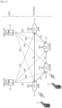
FIG. 1 shows an example of a wireless communication system to which technical features of the present invention can be applied. -
FIG. 2 shows another example of a wireless communication system to which technical features of the present invention can be applied. -
FIG. 3 shows a block diagram of a user plane protocol stack to which technical features of the present invention can be applied. -
FIG. 4 shows a block diagram of a control plane protocol stack to which technical features of the present invention can be applied. -
FIG. 5 shows RRC connection resume procedure. -
FIG. 6 shows an example of a method for managing UE context according to an embodiment. -
FIG. 7 shows another example of a method for managing LTE context according to an example useful for understanding the invention. -
FIG. 8 shows an example of a method for managing UE context according to the present invention. -
FIG. 9 shows a structure of network according to an example useful for understanding of the present invention. -
FIG. 10 shows an example of a method for managing UE context according to the present invention. -
FIG. 11 shows a structure of network according to an embodiment of the present invention. -
FIG. 12 shows an example of a method for managing UE context according to the present invention. -
FIG. 13 shows a structure of UE according to an embodiment of the present invention. - The technical features described below may be used by a communication standard by the 3rd generation partnership project (3GPP) standardization organization, a communication standard by the institute of electrical and electronics engineers (IEEE), etc. For example, the communication standards by the 3GPP standardization organization include long-term evolution (LTE) and/or evolution of LTE systems. The evolution of LTE systems includes LTE-advanced (LTE-A), LTE-A Pro, and/or 5G new radio (NR). The communication standard by the IEEE standardization organization includes a wireless local area network (WLAN) system such as IEEE 802.11a/b/g/n/ac/ax. The above system uses various multiple access technologies such as orthogonal frequency division multiple access (OFDMA) and/or single carrier frequency division multiple access (SC-FDMA) for downlink (DL) and/or uplink (DL). For example, only OFDMA may be used for DL and only SC-FDMA may be used for UL. Alternatively, OFDMA and SC-FDMA may be used for DL and/or UL.
-
FIG. 1 shows an example of a wireless communication system to which technical features of the present invention can be applied. Specifically,FIG. 1 shows a system architecture based on an evolved-UMTS terrestrial radio access network (E-UTRAN). The aforementioned LTE is a part of an evolved-UTMS (e-UMTS) using the E-UTRAN. - Referring to
FIG. 1 , the wireless communication system includes one or more user equipment (UE; 10), an E-UTRAN and an evolved packet core (EPC). The UE 10 refers to a communication equipment carried by a user. The UE 10 may be fixed or mobile. The UE 10 may be referred to as another terminology, such as a mobile station (MS), a user terminal (UT), a subscriber station (SS), a wireless device, etc. - The E-UTRAN consists of one or more base station (BS) 20. The BS 20 provides the E-UTRA user plane and control plane protocol terminations towards the UE 10. The
BS 20 is generally a fixed station that communicates with theUE 10. TheBS 20 hosts the functions, such as inter-cell radio resource management (MME), radio bearer (RB) control, connection mobility control, radio admission control, measurement configuration/provision, dynamic resource allocation (scheduler), etc. The BS may be referred to as another terminology, such as an evolved NodeB (eNB), a base transceiver system (BTS), an access point (AP), etc. - A downlink (DL) denotes communication from the
BS 20 to theUE 10. An uplink (UL) denotes communication from theUE 10 to theBS 20. A sidelink (SL) denotes communication between theUEs 10. In the DL, a transmitter may be a part of theBS 20, and a receiver may be a part of theUE 10. In the UL, the transmitter may be a part of theUE 10, and the receiver may be a part of theBS 20. In the SL, the transmitter and receiver may be a part of theUE 10. - The EPC includes a mobility management entity (MME), a serving gateway (S-GW) and a packet data network (PDN) gateway (P-GW). The MME hosts the functions, such as non-access stratum (NAS) security, idle state mobility handling, evolved packet system (EPS) bearer control, etc. The S-GW hosts the functions, such as mobility anchoring, etc. The S-GW is a gateway having an E-UTRAN as an endpoint. For convenience, MME/S-
GW 30 will be referred to herein simply as a "gateway," but it is understood that this entity includes both the MME and S-GW. The P-GW hosts the functions, such as UE Internet protocol (IP) address allocation, packet filtering, etc. The P-GW is a gateway having a PDN as an endpoint. The P-GW is connected to an external network. - The
UE 10 is connected to theBS 20 by means of the Uu interface. TheUEs 10 are interconnected with each other by means of the PC5 interface. TheBSs 20 are interconnected with each other by means of the X2 interface. TheBSs 20 are also connected by means of the S1 interface to the EPC, more specifically to the MME by means of the S1-MME interface and to the S-GW by means of the S1-U interface. The S1 interface supports a many-to-many relation between MMEs / S-GWs and BSs. -
FIG. 2 shows another example of a wireless communication system to which technical features of the present invention can be applied. Specifically,FIG. 2 shows a system architecture based on a 5G new radio access technology (NR) system. The entity used in the 5G NR system (hereinafter, simply referred to as "NR") may absorb some or all of the functions of the entities introduced inFIG. 1 (e.g. eNB, MME, S-GW). The entity used in the NR system may be identified by the name "NG" for distinction from the LTE/LTE-A. - Referring to
FIG. 2 , the wireless communication system includes one ormore UE 11, a next-generation RAN (NG-RAN) and a 5th generation core network (5GC). The NG-RAN consists of at least one NG-RAN node. The NG-RAN node is an entity corresponding to theBS 10 shown inFIG. 1 . The NG-RAN node consists of at least one gNB 21 and/or at least one ng-eNB 22. ThegNB 21 provides NR user plane and control plane protocol terminations towards theUE 11. The ng-eNB 22 provides E-UTRA user plane and control plane protocol terminations towards theUE 11. - The 5GC includes an access and mobility management function (AMF), a user plane function (UPF) and a session management function (SMF). The AMF hosts the functions, such as NAS security, idle state mobility handling, etc. The AMF is an entity including the functions of the conventional MME. The UPF hosts the functions, such as mobility anchoring, protocol data unit (PDU) handling. The UPF an entity including the functions of the conventional S-GW. The SMF hosts the functions, such as UE IP address allocation, PDU session control.
- The gNBs and ng-eNBs are interconnected with each other by means of the Xn interface. The gNBs and ng-eNBs are also connected by means of the NG interfaces to the 5GC, more specifically to the AMF by means of the NG-C interface and to the UPF by means of the NG-U interface.
- A protocol structure between network entities described above is described. On the system of
FIG. 1 and/orFIG. 2 , layers of a radio interface protocol between the UE and the network (e.g. NG-RAN and/or E-UTRAN) may be classified into a first layer (L1), a second layer (L2), and a third layer (L3) based on the lower three layers of the open system interconnection (OSI) model that is well-known in the communication system. -
FIG. 3 shows a block diagram of a user plane protocol stack to which technical features of the present invention can be applied.FIG. 4 shows a block diagram of a control plane protocol stack to which technical features of the present invention can be applied. The user/control plane protocol stacks shown inFIG. 3 and FIG. 4 are used in NR. However, user/control plane protocol stacks shown inFIG. 3 and FIG .4 may be used in LTE/LTE-A without loss of generality, by replacing gNB/AMF with eNB/ MME. - Referring to
FIG. 3 and FIG. 4 , a physical (PHY) layer belonging to L1. The PHY layer offers information transfer services to media access control (MAC) sublayer and higher layers. The PHY layer offers to the MAC sublayer transport channels. Data between the MAC sublayer and the PHY layer is transferred via the transport channels. Between different PHY layers, i.e., between a PHY layer of a transmission side and a PHY layer of a reception side, data is transferred via the physical channels. - The MAC sublayer belongs to L2. The main services and functions of the MAC sublayer include mapping between logical channels and transport channels, multiplexing/de-multiplexing of MAC service data units (SDUs) belonging to one or different logical channels into/from transport blocks (TB) delivered to/from the physical layer on transport channels, scheduling information reporting, error correction through hybrid automatic repeat request (HARQ), priority handling between UEs by means of dynamic scheduling, priority handling between logical channels of one UE by means of logical channel prioritization (LCP), etc. The MAC sublayer offers to the radio link control (RLC) sublayer logical channels.
- The RLC sublayer belong to L2. The RLC sublayer supports three transmission modes, i.e. transparent mode (TM), unacknowledged mode (UM), and acknowledged mode (AM), in order to guarantee various quality of services (QoS) required by radio bearers. The main services and functions of the RLC sublayer depend on the transmission mode. For example, the RLC sublayer provides transfer of upper layer PDUs for all three modes, but provides error correction through ARQ for AM only. In LTE/LTE-A, the RLC sublayer provides concatenation, segmentation and reassembly of RLC SDUs (only for UM and AM data transfer) and re-segmentation of RLC data PDUs (only for AM data transfer). In NR, the RLC sublayer provides segmentation (only for AM and UM) and re-segmentation (only for AM) of RLC SDUs and reassembly of SDU (only for AM and UM). That is, the NR does not support concatenation of RLC SDUs. The RLC sublayer offers to the packet data convergence protocol (PDCP) sublayer RLC channels.
- The PDCP sublayer belong to L2. The main services and functions of the PDCP sublayer for the user plane include header compression and decompression, transfer of user data, duplicate detection, PDCP PDU routing, retransmission of PDCP SDUs, ciphering and deciphering, etc. The main services and functions of the PDCP sublayer for the control plane include ciphering and integrity protection, transfer of control plane data, etc.
- The service data adaptation protocol (SDAP) sublayer belong to L2. The SDAP sublayer is only defined in the user plane. The SDAP sublayer is only defined for NR. The main services and functions of SDAP include, mapping between a QoS flow and a data radio bearer (DRB), and marking QoS flow ID (QFI) in both DL and UL packets. The SDAP sublayer offers to 5GC QoS flows.
- A radio resource control (RRC) layer belongs to L3. The RRC layer is only defined in the control plane. The RRC layer controls radio resources between the UE and the network. To this end, the RRC layer exchanges RRC messages between the UE and the BS. The main services and functions of the RRC layer include broadcast of system information related to AS and NAS, paging, establishment, maintenance and release of an RRC connection between the UE and the network, security functions including key management, establishment, configuration, maintenance and release of radio bearers, mobility functions, QoS management functions, UE measurement reporting and control of the reporting, NAS message transfer to/from NAS from/to UE.
- In other words, the RRC layer controls logical channels, transport channels, and physical channels in relation to the configuration, reconfiguration, and release of radio bearers. A radio bearer refers to a logical path provided by L1 (PHY layer) and L2 (MAC/RLC/PDCP/SDAP sublayer) for data transmission between a UE and a network. Setting the radio bearer means defining the characteristics of the radio protocol layer and the channel for providing a specific service, and setting each specific parameter and operation method. Radio bearer may be divided into signaling RB (SRB) and data RB (DRB). The SRB is used as a path for transmitting RRC messages in the control plane, and the DRB is used as a path for transmitting user data in the user plane.
- An RRC state indicates whether an RRC layer of the UE is logically connected to an RRC layer of the E-UTRAN. In LTE/LTE-A, when the RRC connection is established between the RRC layer of the UE and the RRC layer of the E-UTRAN, the UE is in the RRC connected state (RRC_CONNECTED). Otherwise, the UE is in the RRC idle state (RRC_IDLE). In NR, the RRC inactive state (RRC_INACTIVE) is additionally introduced. RRC_INACTIVE may be used for various purposes. For example, the massive machine type communications (MMTC) UEs can be efficiently managed in RRC_INACTIVE. When a specific condition is satisfied, transition is made from one of the above three states to the other.
- A predetermined operation may be performed according to the RRC state. In RRC_IDLE, public land mobile network (PLMN) selection, broadcast of system information (SI), cell re-selection mobility, core network (CN) paging and discontinuous reception (DRX) configured by NAS may be performed. The UE shall have been allocated an identifier (ID) which uniquely identifies the UE in a tracking area. No RRC context stored in the base station.
- In RRC_CONNECTED, the UE has an RRC connection with the network (i.e. E-UTRAN/NG-RAN). Network-CN connection (both C/U-planes) is also established for UE. The UE AS context is stored in the network and the UE. The RAN knows the cell which the UE belongs to. The network can transmit and/or receive data to/from UE. Network controlled mobility including measurement is also performed.
- Most of operations performed in RRC_IDLE may be performed in RRC_INACTIVE. But, instead of CN paging in RRC_IDLE, RAN paging is performed in RRC_INACTIVE. In other words, in RRC_IDLE, paging for mobile terminated (MT) data is initiated by core network and paging area is managed by core network. In RRC_INACTIVE, paging is initiated by NG-RAN, and RAN-based notification area (RNA) is managed by NG-RAN. Further, instead of DRX for CN paging configured by NAS in RRC_IDLE, DRX for RAN paging is configured by NG-RAN in RRC_INACTIVE. Meanwhile, in RRC_INACTIVE, 5GC-NG-RAN connection (both C/U-planes) is established for UE, and the UE AS context is stored in NG-RAN and the UE. NG-RAN knows the RNA which the UE belongs to.
- NAS layer is located at the top of the RRC layer. The NAS control protocol performs the functions, such as authentication, mobility management, security control.
- The physical channels may be modulated according to OFDM processing and utilizes time and frequency as radio resources. The physical channels consist of a plurality of orthogonal frequency division multiplexing (OFDM) symbols in time domain and a plurality of subcarriers in frequency domain. One subframe consists of a plurality of OFDM symbols in the time domain. A resource block is a resource allocation unit, and consists of a plurality of OFDM symbols and a plurality of subcarriers. In addition, each subframe may use specific subcarriers of specific OFDM symbols (e.g. first OFDM symbol) of the corresponding subframe for a physical downlink control channel (PDCCH), i.e. L1/L2 control channel. A transmission time interval (TTI) is a basic unit of time used by a scheduler for resource allocation. The TTI may be defined in units of one or a plurality of slots, or may be defined in units of mini-slots.
- The transport channels are classified according to how and with what characteristics data are transferred over the radio interface. DL transport channels include a broadcast channel (BCH) used for transmitting system information, a downlink shared channel (DL-SCH) used for transmitting user traffic or control signals, and a paging channel (PCH) used for paging a UE. UL transport channels include an uplink shared channel (UL-SCH) for transmitting user traffic or control signals and a random access channel (RACH) normally used for initial access to a cell.
- Different kinds of data transfer services are offered by MAC sublayer. Each logical channel type is defined by what type of information is transferred. Logical channels are classified into two groups: control channels and traffic channels.
- Control channels are used for the transfer of control plane information only. The control channels include a broadcast control channel (BCCH), a paging control channel (PCCH), a common control channel (CCCH) and a dedicated control channel (DCCH). The BCCH is a DL channel for broadcasting system control information. The PCCH is DL channel that transfers paging information, system information change notifications. The CCCH is a channel for transmitting control information between UEs and network. This channel is used for UEs having no RRC connection with the network. The DCCH is a point-to-point bi-directional channel that transmits dedicated control information between a UE and the network. This channel is used by UEs having an RRC connection.
- Traffic channels are used for the transfer of user plane information only. The traffic channels include a dedicated traffic channel (DTCH). The DTCH is a point-to-point channel, dedicated to one UE, for the transfer of user information. The DTCH can exist in both UL and DL.
- Regarding mapping between the logical channels and transport channels, in DL, BCCH can be mapped to BCH, BCCH can be mapped to DL-SCH, PCCH can be mapped to PCH, CCCH can be mapped to DL-SCH, DCCH can be mapped to DL-SCH, and DTCH can be mapped to DL-SCH. In UL, CCCH can be mapped to UL-SCH, DCCH can be mapped to UL- SCH, and DTCH can be mapped to UL-SCH.
- RRC_INACTIVE is a state where a UE remains in CM-CONNECTED and can move within an area configured by NG-RAN (the RNA) without notifying NG-RAN. In RRC_INACTIVE, the last serving gNB node keeps the UE context and the UE-associated NG connection with the serving AMF and UPF.
- If the last serving gNB receives DL data from the UPF or DL signalling from the AMF while the UE is in RRC_INACTIVE, it pages in the cells corresponding to the RNA and may send XnAP RAN Paging to neighbour gNB(s) if the RNA includes cells of neighbour gNB(s).
- A UE in the RRC_INACTIVE state can be configured with an RNA, where:
- the RNA can cover a single or multiple cells, and can be smaller than CN area;
- a RAN-based notification area update (RNAU) is periodically sent by the UE and is also sent when the cell reselection procedure of the UE selects a cell that does not belong to the configured RNA.
- There are several different alternatives on how the RNA can be configured:
- List of cells:
- A UE is provided an explicit list of cells (one or more) that constitute the RNA.
- List of RAN areas:
- A UE is provided (at least one) RAN area ID, where a RAN area is a subset of a CN Tracking Area;
- A cell broadcasts (at least one) RAN area ID in the system information so that a UE knows which area the cell belongs to.
- The UE triggers transition from RRC_INACTIVE to RRC_CONNECTED as follow.
-
FIG. 5 shows RRC connection resume procedure. - In step S502, the UE is in RRC_inactive/CM-connected state.
- In step S504, the UE resumes from RRC_INACTIVE, providing the I-RNTI allocated by the last serving gNB and appropriate cause value, e.g., RAN notification area update.
- In step S506, the gNB, if able to resolve the gNB identity contained in the I-RNTI, requests the last serving gNB to provide UE Context.
- In step S508, the last serving gNB provides UE context.
- In step S510, the gNB may move the UE to RRC_CONNECTED, or send the UE back to RRC_INACTIVE state or send the UE to RRC_IDLE. If the UE is sent to RRC_IDLE, the following steps are not needed.
- In step S512, if loss of DL user data buffered in the last serving gNB shall be prevented, the gNB provides forwarding addresses.
- In step S514 and S516, the gNB performs path switch.
- In step S518, the gNB triggers the release of the UE resources at the last serving gNB.
- After step S502 above, when the gNB decides to reject the Resume Request and keep the UE in RRC_INACTIVE without any reconfiguration, or when the gNB decides to setup a new RRC connection, SRB0 (without security) can be used. When the gNB decides to reconfigure the UE (e.g. with a new DRX cycle or RNA) or when the gNB decides to push the UE to RRC_IDLE, SRB1 (with at least integrity protection) shall be used.
- As described above, periodic RNAU may be performed using the RRC connection resume procedure. However, referring to
FIG. 5 , whenever the UE transits from the RRC-INACTIVE state to the RRC-CONNECTED state to perform the RNAU, context fetch may occur. In specific, whenever the UE accesses to the gNB to notify the network that it is still reachable in the RAN-based notification area, the UE context should be fetched from the last serving gNB to the new gNB. However, since no data transmission between the UE and gNB may be occurred during the RNAU, the transfer of the UE context towards new gNB causes the unnecessary signalling and additional latency. Therefore, it is needed for the anchor gNB to skip the UE Context Fetch procedure towards new gNB during the periodic RNAU. - Hereinafter, a method for managing UE context according to an embodiment of the present invention is described. In this embodiment, issues for efficient UE context management during periodic RAN-based notification area update (RNAU) are to be handled.
-
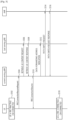
FIG. 6 shows an example of a method for managing UE context according to an embodiment of the present invention. In this embodiment, it may be suggested that when the data transmission is not needed and when the reachability for the UE is confirmed by the periodic RNAU, the anchor gNB will determine to keep the role of anchor gNB and will skip the transfer of the UE context towards new gNB. In other words, the anchor gNB may not perform unnecessary UE context fetch. In order for the new gNB to move the UE back into RRC-INACTIVE state with at least integrity protection, the anchor gNB will generate a RRC message to keep the UE in RRC_INACTIVE state based on the SRB1 configuration for the new gNB. - In this embodiment, the anchor gNB may be a base station of a cell in which the UE was located previously, and the new gNB may be a base station of a cell in which the UE is located currently. In other words, the UE was being served by an anchor gNB, and the UE transits to RRC inactive while being served by the anchor gNB. After that the UE moves toward another gNB, e.g. new gNB while the UE is in RRC inactive state. Further, it is assumed that the anchor gNB and the new gNB are in same RAN-based notification area. Hereinafter, the anchor gNB may be last serving gNB, which may be also referred as gNB1. The new gNB may be current serving gNB, which may be also referred as gNB2.
- In step S602, the UE may be in RRC-INACTIVE state. The NG connection between gNB 1 and NGC is maintained.
- In step S604, when the reachability timer (i.e. periodic RNAU timer) in the UE is expired, the UE may trigger the periodic RNAU procedure to notify the network that the UE is still reachable in the RAN-based notification area. When the UE moves to the gNB2 other than the anchor gNB(=gNB 1), because the gNB 1 and gNB2 are in the same RAN-based notification area, the UE may access to the gNB2. Thus, the UE in RRC-INACTIVE state may send a message for access to the gNB. For example, the UE may transmit a RANDOM ACCESS PREAMBLE message, RRC resume request message or new message to the gNB2.
- In step S606, on receiving the message from the UE, the gNB2 may respond to the UE. For example, the gNB2 may transmit RANDOM ACCESS RESPONSE message to the UE.
- In step S608, in order to resume the RRC connection, the UE may send the RRC RESUME REQUEST message or new message to the gNB2. This message may include the Resume ID to identify the UE context in the gNB. The RRC establishment cause about the RNAU is included in this message to inform the network of triggering the RNAU. In other words, the UE may transmit a message informing that the RRC connection resume is related to the RNAU. For example, the UE may provide the I-RNTI allocated by the last serving gNB and appropriate cause value, e.g., RAN notification area update.
- In step S610, upon reception of the RRC RESLTME REQUEST message or new message, the gNB2 may check whether it is able to find the UE context related to the Resume ID or not. If not, the gNB2 may identify the anchor gNB(=gNB 1) with the Xn interface which has provided the Resume ID. When to find the anchor gNB(=gNB 1), the gNB2 may decide to fetch the UE context from the gNB1 by using the existing Retrieve UE Context procedure or new procedure via the Xn interface. Therefore, the gNB2 may send to the gNB 1 the UE context request message or new message. The UE context request message will be a RETRIEVE UE CONTEXT REQUEST message. This message will include the Location update indication or RRC establishment cause to indicate that the UE accesses to the gNB2 for checking the reachability. In addition, the SRB 1 configuration for gNB2 may be included in this message. That is, the gNB2, if able to resolve the gNB identity contained in the I-RNTI, may request the last serving gNB to provide UE Context, providing the cause value received in step S610.
- In step S612, on receiving the message including the Resume ID from the UE, the gNB 1 may check whether it is able to find the UE context related to the Resume ID or not. Based on the RRC establishment cause or Location update indication in the RETRIEVE UE CONTEXT REQUEST message, the gNB1 can be also aware of that this procedure is the RNAU for the UE to notify the network that it is still reachable. When to exactly find the UE context based on the Resume ID, the gNB 1 may reset the RNAU timer for that UE. Then, if the UE remains within the same RAN-based notification area and there is no data transmission between the gNB 1 and UE, the gNB 1 may decide to keep the role of anchor gNB. In this case, the gNB 1 may not forward the UE context to the gNB2. In order for the gNB2 to move the UE back into RRC-INACTIVE state with at least integrity protection, the gNB1 may generate a RRC message that keeps the UE in RRC_INACTIVE state. The RRC message may request the UE to move to a RRC_INACTIVE state. For example, the RRC message may be RRC release message.
- In step S614, the gNB 1 will send to the gNB2 the RRC message via a container in UE context response message. That is, the UE context response message will include the container which piggybacks the RRC message. The UE context response message may be a RETRIEVE UE CONTEXT FAILURE message including an encapsulated RRC release message. Further, the RRC release message may include suspend configuration, if the last serving gNB decides to keep the UE in RRC_INACTIVE. If the RRC release message does not include the suspend configuration, the UE received that RRC release message may transit to RRC_IDLE state. This UE context response message may not include the UE context.
- In step S616, on receiving the message from the gNB 1, the gNB2 will know the anchor gNB's intention of that it decides not to relocate the anchor gNB. Therefore, the gNB2 may not trigger the Path Switch procedure towards to the NGC. The gNB2 will transparently forward to the UE the RRC message. Thus, the gNB2 may forward RRC release message and suspend configuration to the UE. The RRC message sent by the gNB2 to the UE may be at least one of RRC RESUME message or the RRC RELEASE message.
- In step S618, the UE may be still in RRC-INACTIVE state.
- According to an embodiment of the present invention, when the periodic RNAU is triggered, the anchor gNB can remove unnecessary signaling by skipping the UE context fetch towards new gNB.
-
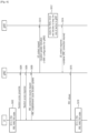
FIG. 7 shows another example of a method for managing UE context according to an embodiment. In this embodiment, it may be suggested that when the data transmission is not needed and the reachability for the UE is confirmed by the periodic RNAU, the anchor gNB may determine to keep the role of anchor gNB. However, in order for the new gNB to move the UE back into RRC-INACTIVE state with at least integrity protection, the anchor gNB may deliver the UE context to the new gNB with the Context release indication. Based on this indication, after generating and sending the RRC resume message or RRC release message to the UE, new gNB may enable to release its context for that UE. - In this embodiment, the anchor gNB may be a base station of a cell in which the UE was located previously, and the new gNB may be a base station of a cell in which the UE is located currently. In other words, the UE was being served by an anchor gNB, and the UE transits to RRC inactive while being served by the anchor gNB. After that the UE moves toward another gNB, e.g. new gNB while the UE is in RRC inactive state. Further, it is assumed that the anchor gNB and the new gNB are in same RAN-based notification area. Hereinafter, the anchor gNB may be last serving gNB, which may be also referred as gNB1. The new gNB may be current serving gNB, which may be also referred as gNB2.
- In step S702, the UE may be in RRC-INACTIVE state. The NG connection between gNB 1 and NGC is maintained.
- In step S704, when the reachability timer in the UE is expired, the UE may trigger the Periodic RNAU procedure to notify the network that the UE is still reachable in the RAN-based notification area. When the UE moves to the gNB2 other than the anchor gNB(=gNB1), because of the gNB1 and gNB2 are in the same RAN-based notification area, the UE may access to the gNB2. Thus, the UE in RRC-INACTIVE state may send a message for access to the gNB. For example, the UE may transmit a RANDOM ACCESS PREAMBLE message, RRC resume request message or new message to the gNB2.
- In step S706, on receiving the message from the UE, the gNB2 may respond to the UE. For example, the gNB2 may transmit RANDOM ACCESS RESPONSE message to the UE.
- In step S708, in order to resume the RRC connection, the UE may send the RRC RESUME REQUEST message or new message to the gNB2. This message may include the Resume ID to identify the UE context in the gNB. The RRC establishment cause about the RNAU is included in this message to inform the network of triggering the RNAU. In other words, the UE may transmit a message informing that the RRC connection resume is related to the RNAU. For example, the UE may provide the I-RNTI allocated by the last serving gNB and appropriate cause value, e.g., RAN notification area update.
- In step S710, upon reception of the RRC RESUME REQUEST message or new message, the gNB2 may check whether it is able to find the UE context related to the Resume ID or not. If not, the gNB2 may identify the anchor gNB(=gNB1) with the Xn interface which has provided the Resume ID. When to find the anchor gNB(=gNB1), the gNB2 may decide to fetch the UE context from the gNB 1 by using the existing Retrieve UE Context procedure or new procedure via the Xn interface. Therefore, the gNB2 may send to the gNB1 the UE context request message or new message. The UE context request message may be a RETRIEVE UE CONTEXT REQUEST message. This message may include the Location update indication or RRC establishment cause to indicate that the UE accesses to the gNB2 for checking the reachability. That is, the gNB2, if able to resolve the gNB identity contained in the I-RNTI, may request the last serving gNB to provide UE Context, providing the cause value received in step S708 (via RRC resume request message).
- In step S712, on receiving the message including the Resume ID from the UE, the gNB 1 may check whether it is able to find the UE context related to the Resume ID or not. Based on the RRC establishment cause or Location update indication in the RETRIEVE UE CONTEXT REQUEST message, the gNB 1 may be also aware of that this procedure is the RNAU for the UE to notify the network that it is still reachable. When to exactly find the UE context based on the Resume ID, the gNB1 may reset the RNAU timer for that UE. Then, if the UE remains within the same RAN-based notification area and there is no data transmission between the gNB1 and UE, the gNB 1 may decide to keep the role of anchor gNB.
- In step S714, the gNB1 may send to the gNB2 the UE context response message or new message. The UE context response may be a RETRIEVE UE CONTEXT RESPONSE message. When the gNB1 decides not to relocate the anchor gNB, the context release indication may be also included with the UE context response message.
- In step S716, on receiving the message from the gNB1, the gNB2 may know the anchor gNB's intention of that it decides not to relocate the anchor gNB based on the context release indication. Therefore, the gNB2 just generates the RRC CONNECTION RESUME message based on the UE context received from the gNB 1 and sends it to the UE in order to move the UE back into the RRC-INACTIVE state with at least integrity protection.
- In step S718, the UE may be still in RRC-INACTIVE state.
- In step S720, the gNB2 may release the context for the UE in the RRC-INACTIVE state.
- According to an embodiment of the present invention, when the periodic RNAU is triggered, the anchor gNB may remove unnecessary signallings by skipping the UE context fetch towards new gNB.
- Further, the embodiments of the present invention can be also applied to CU-DU split in NR case for resuming the UE context in the RRC-INACTIVE UE. This solution can be also applied to CU-DU split in LTE case for resuming the UE context in the NB-IoT UE and the lightly connected UE.
- According to embodiments of the present invention, last serving gNB does not need to send the UE context to the current serving gNB, and the current serving gNB does not need to perform the core network and path switch procedures, if the UE sends a periodic RNAU and the context of the UE does not need to be moved to the serving gNB. That is, the anchor gNB can selectively fetch the UE context towards new gNB in order to relocate the role of the anchor gNB. For the periodic RNAU, since the UE moves back into the RRC-INACTIVE state, it is possible for the anchor gNB to decide whether to transfer UE context to new gNB. In addition, the anchor gNB may confirm the reachability for the UE without the state transition procedure. Therefore, these embodiments can make the UE's experience better (e.g. state transition from the RRC-INACTIVE state (or light connection in LTE) to the RRC-CONNECTED state can be removed).
-
FIG. 8 shows an example of a method for managing UE context according to the present invention. - In step S802, the first base station (BS) may receive a UE context request message including a radio resource control (RRC) establishment cause from a second BS. The first BS and the second BS may be located in a same radio access network (RAN)-based notification area (RNA). The first BS may be last serving base station, and the second BS may be a current serving base station.
- In step S804, the first base station may transmit a UE context response message to the second BS when the RRC establishment cause is related to RNA update. The UE context response message may piggyback a RRC message requesting a UE to move to a RRC inactive state. The first base station may determine that the first BS keeps a UE context based on the RRC establishment cause which is related to RNA update. Further, the first base station may generate the UE context response message not to include a UE context requested by the UE context request message. The RRC message may be RRC resume message or RRC release message. The UE context response message may be retrieve UE context fail message.
- According to embodiments of the present invention, last serving gNB does not need to send the UE context to the current serving gNB, and the current serving gNB does not need to perform the core network and path switch procedures, if the UE sends a periodic RNAU and the context of the UE does not need to be moved to the serving gNB. That is, the anchor gNB can selectively fetch the UE context towards new gNB in order to relocate the role of the anchor gNB. For the periodic RNAU, since the UE moves back into the RRC-INACTIVE state, it is possible for the anchor gNB to decide whether to transfer UE context to new gNB.
-
FIG. 9 shows a structure of network according to an embodiment of the present invention. Afirst network node 910 shown inFIG. 9 may be a first base station (BS), which may be one of eNB or gNB. Asecond network node 920 may be a second BS, which may be one of eNB or gNB. - A
first network node 910 includes aprocessor 911, amemory 912, and atransceiver 913. Thememory 912 is coupled to theprocessor 911, and stores a variety of information for driving theprocessor 911. Thetransceiver 913 is coupled to theprocessor 911, and transmits and/or receives a radio signal. Theprocessor 911 implements the proposed functions, procedures, and/or methods. In the aforementioned embodiments, an operation of the first network node may be implemented by theprocessor 911. - The
processors 911 may include application-specific integrated circuit (ASIC), other chipset, logic circuit and/or data processing device. The memories may include read-only memory (ROM), random access memory (RAM), flash memory, memory card, storage medium and/or other storage device. The transceivers may include baseband circuitry to process radio frequency signals. When the embodiments are implemented in software, the techniques described herein can be implemented with modules (e.g., procedures, functions, and so on) that perform the functions described herein. The modules can be stored in memories and executed by processors. The memories can be implemented within the processors or external to the processors in which case those can be communicatively coupled to the processors via various means as is known in the art. - The
processor 911 may be configured to control thetransceiver 913 to receive a UE context request message including a radio resource control (RRC) establishment cause from a second BS. The first BS and the second BS may be located in a same radio access network (RAN)-based notification area (RNA). The first BS may be last serving base station, and the second BS may be a current serving base station. - The
processor 911 may be configured to control thetransceiver 913 to transmit a UE context response message to the second BS if the RRC establishment cause is related to RNA update. The UE context response message may piggyback a RRC message requesting a UE to move to a RRC inactive state. The first base station may determine that the first BS keeps a UE context based on the RRC establishment cause which is related to RNA update. Further, the first base station may generate the UE context response message not to include a UE context requested by the UE context request message. The RRC message may be RRC resume message or RRC release message. The UE context response message may be retrieve UE context fail message. - According to embodiments of the present invention, last serving gNB does not need to send the UE context to the current serving gNB, and the current serving gNB does not need to perform the core network and path switch procedures, if the UE sends a periodic RNAU and the context of the UE does not need to be moved to the serving gNB. That is, the anchor gNB can selectively fetch the UE context towards new gNB in order to relocate the role of the anchor gNB. For the periodic RNAU, since the UE moves back into the RRC-INACTIVE state, it is possible for the anchor gNB to decide whether to transfer UE context to new gNB.
-
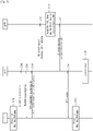
FIG. 10 shows an example of a method for managing UE context according to the present invention. - In step S1002, the second base station (BS) may receive a RRC resume request message including a RRC establishment cause from a user equipment (UE). The RRC establishment cause may be related to a radio access network (RAN)-based notification area (RNA) update. The first BS may be last serving base station, and the second BS may be a current serving base station.
- In step S1004, the second BS may transmit a UE context request message including the RRC establishment cause to a first BS. The first BS and the second BS may be located in a same RNA.
- In step S1006, the second BS may receive a UE context response message from the first BS. The UE context response message may piggyback a RRC message requesting the UE to move to a RRC inactive state. The UE context response message may not include a UE context requested by the UE context request message. The UE context response message may be retrieve UE context fail message.
- In step S1008, the second BS may forward the RRC message to the UE.
- According to embodiments of the present invention, last serving gNB does not need to send the UE context to the current serving gNB, and the current serving gNB does not need to perform the core network and path switch procedures, if the UE sends a periodic RNAU and the context of the UE does not need to be moved to the serving gNB. That is, the anchor gNB can selectively fetch the UE context towards new gNB in order to relocate the role of the anchor gNB. For the periodic RNAU, since the UE moves back into the RRC-INACTIVE state, it is possible for the anchor gNB to decide whether to transfer UE context to new gNB.
-
FIG. 11 shows a structure of network according to an embodiment of the present invention. Afirst network node 1110 shown inFIG. 11 may be a first base station (BS), which may be one of eNB or gNB. Asecond network node 1120 may be a second BS, and a second network node 1130 may be a UE. - A
second network node 1120 includes aprocessor 1121, amemory 1122, and atransceiver 1123. Thememory 1122 is coupled to theprocessor 1121, and stores a variety of information for driving theprocessor 1121. Thetransceiver 1123 is coupled to theprocessor 1121, and transmits and/or receives a radio signal. Theprocessor 1121 implements the proposed functions, procedures, and/or methods. In the aforementioned embodiments, an operation of the first network node may be implemented by theprocessor 1121. - The
processors 1121 may include application-specific integrated circuit (ASIC), other chipset, logic circuit and/or data processing device. The memories may include read-only memory (ROM), random access memory (RAM), flash memory, memory card, storage medium and/or other storage device. The transceivers may include baseband circuitry to process radio frequency signals. When the embodiments are implemented in software, the techniques described herein can be implemented with modules (e.g., procedures, functions, and so on) that perform the functions described herein. The modules can be stored in memories and executed by processors. The memories can be implemented within the processors or external to the processors in which case those can be communicatively coupled to the processors via various means as is known in the art. - The
processor 1121 may be configured to control thetransceiver 1123 to receive a RRC resume request message including a RRC establishment cause from a user equipment (UE). The RRC establishment cause may be related to a radio access network (RAN)-based notification area (RNA) update. The first BS may be last serving base station, and the second BS may be a current serving base station. - The
processor 1121 may be configured to control thetransceiver 1123 to transmit a UE context request message including the RRC establishment cause to a first BS. The first BS and the second BS may be located in a same RNA. - The
processor 1121 may be configured to control thetransceiver 1123 to receive a UE context response message from the first BS. The UE context response message may piggyback a RRC message requesting the UE to move to a RRC inactive state. The UE context response message may not include a UE context requested by the UE context request message. The UE context response message may be retrieve UE context fail message. - The
processor 1121 may be configured to control thetransceiver 1123 to forward the RRC message requesting the UE to move to a RRC inactive state. - According to embodiments of the present invention, last serving gNB does not need to send the UE context to the current serving gNB, and the current serving gNB does not need to perform the core network and path switch procedures, if the UE sends a periodic RNAU and the context of the UE does not need to be moved to the serving gNB. That is, the anchor gNB can selectively fetch the UE context towards new gNB in order to relocate the role of the anchor gNB. For the periodic RNAU, since the UE moves back into the RRC-INACTIVE state, it is possible for the anchor gNB to decide whether to transfer UE context to new gNB.
-
FIG. 12 shows an example of a method for managing UE context according to the present invention. - In step S1202, the UE may transmit a RRC resume request message including a RRC establishment cause from a user equipment (UE) to the second BS. The RRC establishment cause may be related to a radio access network (RAN)-based notification area (RNA) update. The second BS may be a current serving base station.
- In step S1204, the UE may receive a RRC message requesting the UE to move to a RRC inactive state from the second BS.
- According to embodiments of the present invention, last serving gNB does not need to send the UE context to the current serving gNB, and the current serving gNB does not need to perform the core network and path switch procedures, if the UE sends a periodic RNAU and the context of the UE does not need to be moved to the serving gNB. That is, the anchor gNB can selectively fetch the UE context towards new gNB in order to relocate the role of the anchor gNB. For the periodic RNAU, since the UE moves back into the RRC-INACTIVE state, it is possible for the anchor gNB to decide whether to transfer UE context to new gNB.
-
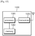
FIG. 13 shows a structure of UE according to an embodiment of the present invention. - According to an embodiment of the present invention, the
UE 1300 may comprisetransceiver 1302, processor 1304 and memory 1306. The memory 1306 is coupled to the processor 1304, and stores a variety of information for driving the processor 1304. Thetransceiver 1302 is coupled to the processor 1304, and transmits and/or receives a radio signal. The processor 1304 implements the proposed functions, procedures, and/ or methods. In the aforementioned embodiments, an operation of theUE 1300 may be implemented by the processor 1304. - The processor 1304 may include application-specific integrated circuit (ASIC), other chipset, logic circuit and/or data processing device. The memory 1306 may include read-only memory (ROM), random access memory (RAM), flash memory, memory card, storage medium and/or other storage device. The
transceiver 1302 may include baseband circuitry to process radio frequency signals. When the embodiments are implemented in software, the techniques described herein can be implemented with modules (e.g., procedures, functions, and so on) that perform the functions described herein. The modules can be stored in memories and executed by processor 1304. The memory 1306 can be implemented within the processor 1304 or external to the processor 1204 in which case those can be communicatively coupled to the processor 1304 via various means as is known in the art. - The processor 1304 may be configured to control the
transceiver 1302 to transmit a RRC resume request message including a RRC establishment cause from a user equipment (UE) to the second BS. The RRC establishment cause may be related to a radio access network (RAN)-based notification area (RNA) update. The second BS may be a current serving base station. - The processor 1304 may be configured to control the
transceiver 1302 to receive a RRC message requesting the UE to move to a RRC inactive state from the second BS. - According to embodiments of the present invention, last serving gNB does not need to send the UE context to the current serving gNB, and the current serving gNB does not need to perform the core network and path switch procedures, if the UE sends a periodic RNAU and the context of the UE does not need to be moved to the serving gNB. That is, the anchor gNB can selectively fetch the UE context towards new gNB in order to relocate the role of the anchor gNB. For the periodic RNAU, since the UE moves back into the RRC-INACTIVE state, it is possible for the anchor gNB to decide whether to transfer UE context to new gNB.
- In view of the exemplary systems described herein, methodologies that may be implemented in accordance with the disclosed subject matter have been described with reference to several flow diagrams. While for purposed of simplicity, the methodologies are shown and described as a series of steps or blocks, it is to be understood and appreciated that the claimed subject matter is not limited by the order of the steps or blocks, as some steps may occur in different orders or concurrently with other steps from what is depicted and described herein. Moreover, one skilled in the art would understand that the steps illustrated in the flow diagram are not exclusive and other steps may be included or one or more of the steps in the example flow diagram may be deleted without affecting the scope and spirit of the present disclosure.
- What has been described above includes examples of the various aspects. It is, of course, not possible to describe every conceivable combination of components or methodologies for purposes of describing the various aspects, but one of ordinary skill in the art may recognize that many further combinations and permutations are possible. Accordingly, the subject specification is intended to embrace all such alternations, modifications and variations that fall within the scope of the appended claims.
Claims (6)
- A method performed by a first base station, BS, in a wireless communication system, the method comprising:receiving (S610), from a second BS, a retrieve user equipment, UE, context request message which includes (i) a cause informing a radio access network, RAN-based notification area, RNA, update for a UE, and (ii) a signaling radio bearer, SRB1 configuration associated with the second BS,wherein the first BS and the second BS are located in a same RNA, andwherein (S608) the cause informing the RNA update is transmitted, from the UE, via a Radio Resource Control (RRC) connection resume request message;if the UE remains within the same RNA and there is no data transmission between the UE and the first BS, deciding to keep the role of anchor BS and skipping transfer of a UE context for the UE to the second BS;generating an RRC message to keep the UE in RRC inactive state based on the SRB 1 configuration for the second BS (920); ; andtransmitting (S614), to the second BS, a response message in response to the retrieve UE context request message, wherein the response message includes a container which piggybacks an RRC message requesting the UE to move to an RRC inactive state,wherein (S616) the RRC message is to be transparently forwarded to the UE via the second BS.
- The method of claim 1, wherein the response message does not include the UE context.
- The method of claim 1, wherein the first BS is last serving base station, and the second BS is a current serving base station.
- A first base station, BS, (910) for use in a wireless communication system, the first BS (910) comprising:a transceiver (913); anda processor (911) coupled to the transceiver (913),wherein the first BS (910) is configured to:receive, from a second BS (920), a retrieve user equipment, UE, context request message which includes (i) a cause informing a radio access network, RAN-based notification area, RNA, update for a UE, and (ii) a signaling radio bearer, SRB1, configuration associated with the second BS,wherein the first BS and the second BS are in a same RNA, andwherein the cause informing the RNA update is transmitted, from the UE, via a Radio Resource Control (RRC) connection resume request message;if the UE remains within the same RNA and there is no data transmission between the UE and the first BS, decide to keep the role of anchor BS and skip transfer of a UE context for the UE to the second BS;generate an RRC message to keep the UE in RRC inactive state based on the SRB 1 configuration for the second BS (920); andtransmit, to the second BS (920), a response message in response to the retrieve UE context request message, wherein the response message includes a container which piggybacks an RRC message requesting a UE to move to an RRC inactive state,wherein the RRC message is to be transparently forwarded to the UE via the second BS.
- The first BS (910) of claim 4, wherein the response message does not include the UE context.
- The first BS (910) of claim 4, wherein the first BS is last serving base station, and the second BS is a current serving base station.
Applications Claiming Priority (2)
| Application Number | Priority Date | Filing Date | Title |
|---|---|---|---|
| US201762584911P | 2017-11-13 | 2017-11-13 | |
| PCT/KR2018/013752 WO2019093850A1 (en) | 2017-11-13 | 2018-11-13 | Method for managing ue context and device supporting the same |
Publications (3)
| Publication Number | Publication Date |
|---|---|
| EP3704883A1 EP3704883A1 (en) | 2020-09-09 |
| EP3704883A4 EP3704883A4 (en) | 2020-12-02 |
| EP3704883B1 true EP3704883B1 (en) | 2023-04-05 |
Family
ID=66439214
Family Applications (1)
| Application Number | Title | Priority Date | Filing Date |
|---|---|---|---|
| EP18875583.9A Active EP3704883B1 (en) | 2017-11-13 | 2018-11-13 | Method for managing ue context and device supporting the same |
Country Status (4)
| Country | Link |
|---|---|
| US (1) | US11432209B2 (en) |
| EP (1) | EP3704883B1 (en) |
| CN (1) | CN111434131B (en) |
| WO (1) | WO2019093850A1 (en) |
Families Citing this family (32)
| Publication number | Priority date | Publication date | Assignee | Title |
|---|---|---|---|---|
| WO2019093850A1 (en) | 2017-11-13 | 2019-05-16 | Lg Electronics Inc. | Method for managing ue context and device supporting the same |
| TWI680690B (en) * | 2017-11-16 | 2019-12-21 | 香港商鴻穎創新有限公司 | Method of radio access network notification area management for user equipment and base station |
| CN116017785A (en) | 2018-02-09 | 2023-04-25 | 中兴通讯股份有限公司 | RRC state transition method, terminal, CU, DU and computer readable storage Medium |
| KR102425581B1 (en) * | 2018-02-23 | 2022-07-27 | 삼성전자주식회사 | Method and apparatus for performing communication in mobile communication system |
| EP3840522B1 (en) * | 2018-04-02 | 2023-06-28 | Guangdong Oppo Mobile Telecommunications Corp., Ltd. | Methods and devices for controlling rrc state |
| CN110351894A (en) * | 2018-04-04 | 2019-10-18 | 北京三星通信技术研究有限公司 | A kind of method and apparatus authenticating UE |
| KR20190143782A (en) * | 2018-06-21 | 2019-12-31 | 삼성전자주식회사 | Method and apparatus for supporting dual connectivity of a terminal in rrc inactive mode in next generation mobile communication system |
| AU2019316156B2 (en) * | 2018-08-03 | 2022-05-12 | Telefonaktiebolaget Lm Ericsson (Publ) | User plane optimizations for 5G cellular internet of things |
| EP4216608A1 (en) | 2018-08-10 | 2023-07-26 | Fg Innovation Company Limited | Method and apparatus for rrc state transition |
| EP3841785B1 (en) * | 2018-08-22 | 2023-05-31 | Telefonaktiebolaget LM Ericsson (publ) | Ue context forwarding |
| US11937326B2 (en) * | 2018-09-24 | 2024-03-19 | Telefonaktiebolaget Lm Ericsson (Publ) | User equipment (UE) reachability request parameter for suspended radio access network (RAN) |
| WO2020064384A1 (en) * | 2018-09-28 | 2020-04-02 | Nokia Technologies Oy | Connection resume handling |
| EP3921673A2 (en) * | 2019-02-07 | 2021-12-15 | Telefonaktiebolaget LM ERICSSON (PUBL) | User equipment, network node and method for enabling gnss measurements |
| WO2020191059A1 (en) * | 2019-03-19 | 2020-09-24 | Apple Inc. | Signaling for inactive small data transmission without path switching |
| KR20200112288A (en) * | 2019-03-21 | 2020-10-05 | 삼성전자주식회사 | Method and apparatus for measuring frequency in wireless communication system |
| EP3994955A1 (en) * | 2019-07-03 | 2022-05-11 | Nokia Solutions and Networks Oy | Efficient context handling for rrc-inactive in 5g |
| EP3979763A4 (en) * | 2019-07-04 | 2022-06-29 | Guangdong Oppo Mobile Telecommunications Corp., Ltd. | Data transmission method and apparatus, and communication device |
| CN114616917A (en) * | 2019-11-07 | 2022-06-10 | 华为技术有限公司 | RRC connection recovery method and equipment |
| JP7383143B2 (en) * | 2019-11-08 | 2023-11-17 | 華為技術有限公司 | Communication methods and devices |
| CN112996144B (en) * | 2019-12-02 | 2023-01-20 | 大唐移动通信设备有限公司 | Interaction optimization method and device between base stations of terminal in non-activated state and electronic equipment |
| GB2592569A (en) * | 2020-01-22 | 2021-09-08 | Nokia Technologies Oy | Apparatus, method and computer program |
| WO2021232239A1 (en) * | 2020-05-19 | 2021-11-25 | Nokia Shanghai Bell Co., Ltd. | Radio resource control inactive state for remote user equipment |
| CN114071589B (en) * | 2020-07-30 | 2023-04-25 | 展讯通信(上海)有限公司 | Link switching indication method, device, apparatus and storage medium |
| WO2022031704A1 (en) * | 2020-08-03 | 2022-02-10 | Kyungmin Park | Methods, apparatuses and system for uplink resource configuration |
| CN114095138B (en) * | 2020-08-24 | 2023-05-30 | 维沃移动通信有限公司 | User plane data transmission method and network node |
| CN114126046B (en) * | 2020-08-31 | 2023-02-24 | 大唐移动通信设备有限公司 | Communication control method and device for base station, base station and storage medium |
| EP3968696A1 (en) * | 2020-09-15 | 2022-03-16 | Nokia Technologies Oy | Ng based context release and data forwarding for multi-hop mobility |
| US20230217528A1 (en) * | 2020-09-25 | 2023-07-06 | Apple Inc. | Context fetch procedure for inactive direct data transmission |
| US20230039795A1 (en) * | 2021-08-06 | 2023-02-09 | Telefonaktiebolaget Lm Ericsson (Publ) | Identifying a user equipment, ue, for subsequent network reestablishment after a radio link failure during an initial network establishment attempt |
| CN116419253A (en) * | 2021-12-31 | 2023-07-11 | 中国移动通信有限公司研究院 | Communication method, base station, terminal and storage medium |
| WO2023153731A1 (en) * | 2022-02-11 | 2023-08-17 | 엘지전자 주식회사 | Sdt-related communication |
| CN114679756B (en) * | 2022-05-26 | 2022-08-05 | 武汉世炬信息技术有限公司 | Wireless connection state management system and method for user terminal in non-activated state |
Family Cites Families (9)
| Publication number | Priority date | Publication date | Assignee | Title |
|---|---|---|---|---|
| WO2016013647A1 (en) | 2014-07-25 | 2016-01-28 | 京セラ株式会社 | Base station and mobile station |
| WO2017126922A1 (en) * | 2016-01-19 | 2017-07-27 | 엘지전자(주) | Method for resuming connection in wireless communication system and device for same |
| EP3419319A4 (en) * | 2016-02-19 | 2019-10-16 | LG Electronics Inc. -1- | Service request transmission and user equipment, and service request reception and base station |
| EP3435696B1 (en) * | 2016-03-23 | 2021-06-23 | LG Electronics Inc. | Method for tracking area update in wireless communication system and apparatus therefor |
| CN107295515B (en) | 2016-04-01 | 2022-07-19 | 北京三星通信技术研究有限公司 | Method and device for supporting context recovery of User Equipment (UE) between base stations |
| CN115665857A (en) * | 2016-07-13 | 2023-01-31 | 三星电子株式会社 | Access control method and apparatus for use in mobile communication |
| WO2018030866A1 (en) * | 2016-08-11 | 2018-02-15 | 삼성전자 주식회사 | Low power rrc operating method and device |
| US10893568B2 (en) * | 2017-08-18 | 2021-01-12 | Huawei Technologies Co., Ltd. | Location and context management in a RAN INACTIVE mode |
| WO2019093850A1 (en) | 2017-11-13 | 2019-05-16 | Lg Electronics Inc. | Method for managing ue context and device supporting the same |
-
2018
- 2018-11-13 WO PCT/KR2018/013752 patent/WO2019093850A1/en unknown
- 2018-11-13 EP EP18875583.9A patent/EP3704883B1/en active Active
- 2018-11-13 CN CN201880077818.XA patent/CN111434131B/en active Active
- 2018-11-13 US US16/763,545 patent/US11432209B2/en active Active
Also Published As
| Publication number | Publication date |
|---|---|
| EP3704883A1 (en) | 2020-09-09 |
| CN111434131B (en) | 2023-06-20 |
| EP3704883A4 (en) | 2020-12-02 |
| WO2019093850A1 (en) | 2019-05-16 |
| US20200351723A1 (en) | 2020-11-05 |
| US11432209B2 (en) | 2022-08-30 |
| CN111434131A (en) | 2020-07-17 |
Similar Documents
| Publication | Publication Date | Title |
|---|---|---|
| EP3704883B1 (en) | Method for managing ue context and device supporting the same | |
| US11638320B2 (en) | Method and apparatus for resuming RRC connection in CU-DU division scenario | |
| US11363628B2 (en) | Method and apparatus for performing uplink transmission with pre-allocated beams in wireless communication system | |
| US11516737B2 (en) | Method for changing status of WUS operation and device supporting the same | |
| CN109076382B (en) | Data transmission method performed by base station in wireless communication system and apparatus using the same | |
| KR101829115B1 (en) | Method and apparatus for controlling user equipment access in wireless communication system | |
| US11083038B2 (en) | Method for reporting mobility history of UE and device supporting the same | |
| US11039377B2 (en) | Method and device for receiving system information | |
| US10791540B2 (en) | Method and apparatus for keeping SCG configuration | |
| US20200169913A1 (en) | Method and apparatus for modifying mapping rule | |
| US10893569B2 (en) | RRC state changing method of terminal, and device supporting same | |
| US11219088B2 (en) | Method and apparatus for configuring release cause | |
| JP2016535506A (en) | Method and apparatus for transmitting a paging message in a wireless communication system | |
| EP3474590B1 (en) | Method for reporting rrc state of terminal and apparatus for supporting same | |
| EP3355644B1 (en) | Methods and devices by which prioritized service is transmitted | |
| EP3525530B1 (en) | Method and device for configuring ran-based notification area | |
| US11490319B2 (en) | Method and apparatus for signaling of access barring parameters in wireless communication system | |
| US11191006B2 (en) | Method for determining validity of system information block and apparatus supporting same | |
| US20200163123A1 (en) | Method for performing random access procedure and device supporting the same | |
| US10798648B2 (en) | Method for performing PLMN selection and device supporting the same | |
| US10595299B2 (en) | Method and device for altering tracking area on basis of mobility of terminal | |
| US10912057B2 (en) | Method for selecting configuration based on UE speed and device supporting the same |
Legal Events
| Date | Code | Title | Description |
|---|---|---|---|
| STAA | Information on the status of an ep patent application or granted ep patent |
Free format text: STATUS: THE INTERNATIONAL PUBLICATION HAS BEEN MADE |
|
| PUAI | Public reference made under article 153(3) epc to a published international application that has entered the european phase |
Free format text: ORIGINAL CODE: 0009012 |
|
| STAA | Information on the status of an ep patent application or granted ep patent |
Free format text: STATUS: REQUEST FOR EXAMINATION WAS MADE |
|
| 17P | Request for examination filed |
Effective date: 20200603 |
|
| AK | Designated contracting states |
Kind code of ref document: A1 Designated state(s): AL AT BE BG CH CY CZ DE DK EE ES FI FR GB GR HR HU IE IS IT LI LT LU LV MC MK MT NL NO PL PT RO RS SE SI SK SM TR |
|
| AX | Request for extension of the european patent |
Extension state: BA ME |
|
| A4 | Supplementary search report drawn up and despatched |
Effective date: 20201104 |
|
| RIC1 | Information provided on ipc code assigned before grant |
Ipc: H04W 36/08 20090101ALN20201029BHEP Ipc: H04W 76/27 20180101ALI20201029BHEP Ipc: H04W 48/20 20090101ALI20201029BHEP Ipc: H04W 60/04 20090101ALN20201029BHEP Ipc: H04W 60/06 20090101ALN20201029BHEP Ipc: H04W 36/00 20090101ALN20201029BHEP Ipc: H04W 8/14 20090101AFI20201029BHEP Ipc: H04W 88/08 20090101ALI20201029BHEP |
|
| DAV | Request for validation of the european patent (deleted) | ||
| DAX | Request for extension of the european patent (deleted) | ||
| STAA | Information on the status of an ep patent application or granted ep patent |
Free format text: STATUS: EXAMINATION IS IN PROGRESS |
|
| 17Q | First examination report despatched |
Effective date: 20210727 |
|
| GRAP | Despatch of communication of intention to grant a patent |
Free format text: ORIGINAL CODE: EPIDOSNIGR1 |
|
| STAA | Information on the status of an ep patent application or granted ep patent |
Free format text: STATUS: GRANT OF PATENT IS INTENDED |
|
| RIC1 | Information provided on ipc code assigned before grant |
Ipc: H04W 60/06 20090101ALN20220920BHEP Ipc: H04W 60/04 20090101ALN20220920BHEP Ipc: H04W 36/08 20090101ALN20220920BHEP Ipc: H04W 36/00 20090101ALN20220920BHEP Ipc: H04W 48/20 20090101ALI20220920BHEP Ipc: H04W 88/08 20090101ALI20220920BHEP Ipc: H04W 76/27 20180101ALI20220920BHEP Ipc: H04W 8/14 20090101AFI20220920BHEP |
|
| INTG | Intention to grant announced |
Effective date: 20221017 |
|
| GRAS | Grant fee paid |
Free format text: ORIGINAL CODE: EPIDOSNIGR3 |
|
| GRAA | (expected) grant |
Free format text: ORIGINAL CODE: 0009210 |
|
| STAA | Information on the status of an ep patent application or granted ep patent |
Free format text: STATUS: THE PATENT HAS BEEN GRANTED |
|
| AK | Designated contracting states |
Kind code of ref document: B1 Designated state(s): AL AT BE BG CH CY CZ DE DK EE ES FI FR GB GR HR HU IE IS IT LI LT LU LV MC MK MT NL NO PL PT RO RS SE SI SK SM TR |
|
| REG | Reference to a national code |
Ref country code: GB Ref legal event code: FG4D |
|
| REG | Reference to a national code |
Ref country code: DE Ref legal event code: R096 Ref document number: 602018048196 Country of ref document: DE |
|
| REG | Reference to a national code |
Ref country code: CH Ref legal event code: EP |
|
| REG | Reference to a national code |
Ref country code: AT Ref legal event code: REF Ref document number: 1559196 Country of ref document: AT Kind code of ref document: T Effective date: 20230415 |
|
| REG | Reference to a national code |
Ref country code: IE Ref legal event code: FG4D |
|
| REG | Reference to a national code |
Ref country code: LT Ref legal event code: MG9D |
|
| REG | Reference to a national code |
Ref country code: NL Ref legal event code: MP Effective date: 20230405 |
|
| REG | Reference to a national code |
Ref country code: AT Ref legal event code: MK05 Ref document number: 1559196 Country of ref document: AT Kind code of ref document: T Effective date: 20230405 |
|
| PG25 | Lapsed in a contracting state [announced via postgrant information from national office to epo] |
Ref country code: NL Free format text: LAPSE BECAUSE OF FAILURE TO SUBMIT A TRANSLATION OF THE DESCRIPTION OR TO PAY THE FEE WITHIN THE PRESCRIBED TIME-LIMIT Effective date: 20230405 |
|
| PG25 | Lapsed in a contracting state [announced via postgrant information from national office to epo] |
Ref country code: SE Free format text: LAPSE BECAUSE OF FAILURE TO SUBMIT A TRANSLATION OF THE DESCRIPTION OR TO PAY THE FEE WITHIN THE PRESCRIBED TIME-LIMIT Effective date: 20230405 Ref country code: PT Free format text: LAPSE BECAUSE OF FAILURE TO SUBMIT A TRANSLATION OF THE DESCRIPTION OR TO PAY THE FEE WITHIN THE PRESCRIBED TIME-LIMIT Effective date: 20230807 Ref country code: NO Free format text: LAPSE BECAUSE OF FAILURE TO SUBMIT A TRANSLATION OF THE DESCRIPTION OR TO PAY THE FEE WITHIN THE PRESCRIBED TIME-LIMIT Effective date: 20230705 Ref country code: ES Free format text: LAPSE BECAUSE OF FAILURE TO SUBMIT A TRANSLATION OF THE DESCRIPTION OR TO PAY THE FEE WITHIN THE PRESCRIBED TIME-LIMIT Effective date: 20230405 Ref country code: AT Free format text: LAPSE BECAUSE OF FAILURE TO SUBMIT A TRANSLATION OF THE DESCRIPTION OR TO PAY THE FEE WITHIN THE PRESCRIBED TIME-LIMIT Effective date: 20230405 |
|
| PG25 | Lapsed in a contracting state [announced via postgrant information from national office to epo] |
Ref country code: RS Free format text: LAPSE BECAUSE OF FAILURE TO SUBMIT A TRANSLATION OF THE DESCRIPTION OR TO PAY THE FEE WITHIN THE PRESCRIBED TIME-LIMIT Effective date: 20230405 Ref country code: PL Free format text: LAPSE BECAUSE OF FAILURE TO SUBMIT A TRANSLATION OF THE DESCRIPTION OR TO PAY THE FEE WITHIN THE PRESCRIBED TIME-LIMIT Effective date: 20230405 Ref country code: LV Free format text: LAPSE BECAUSE OF FAILURE TO SUBMIT A TRANSLATION OF THE DESCRIPTION OR TO PAY THE FEE WITHIN THE PRESCRIBED TIME-LIMIT Effective date: 20230405 Ref country code: LT Free format text: LAPSE BECAUSE OF FAILURE TO SUBMIT A TRANSLATION OF THE DESCRIPTION OR TO PAY THE FEE WITHIN THE PRESCRIBED TIME-LIMIT Effective date: 20230405 Ref country code: IS Free format text: LAPSE BECAUSE OF FAILURE TO SUBMIT A TRANSLATION OF THE DESCRIPTION OR TO PAY THE FEE WITHIN THE PRESCRIBED TIME-LIMIT Effective date: 20230805 Ref country code: HR Free format text: LAPSE BECAUSE OF FAILURE TO SUBMIT A TRANSLATION OF THE DESCRIPTION OR TO PAY THE FEE WITHIN THE PRESCRIBED TIME-LIMIT Effective date: 20230405 Ref country code: GR Free format text: LAPSE BECAUSE OF FAILURE TO SUBMIT A TRANSLATION OF THE DESCRIPTION OR TO PAY THE FEE WITHIN THE PRESCRIBED TIME-LIMIT Effective date: 20230706 Ref country code: AL Free format text: LAPSE BECAUSE OF FAILURE TO SUBMIT A TRANSLATION OF THE DESCRIPTION OR TO PAY THE FEE WITHIN THE PRESCRIBED TIME-LIMIT Effective date: 20230405 |
|
| PG25 | Lapsed in a contracting state [announced via postgrant information from national office to epo] |
Ref country code: FI Free format text: LAPSE BECAUSE OF FAILURE TO SUBMIT A TRANSLATION OF THE DESCRIPTION OR TO PAY THE FEE WITHIN THE PRESCRIBED TIME-LIMIT Effective date: 20230405 |
|
| REG | Reference to a national code |
Ref country code: DE Ref legal event code: R097 Ref document number: 602018048196 Country of ref document: DE |
|
| PG25 | Lapsed in a contracting state [announced via postgrant information from national office to epo] |
Ref country code: SK Free format text: LAPSE BECAUSE OF FAILURE TO SUBMIT A TRANSLATION OF THE DESCRIPTION OR TO PAY THE FEE WITHIN THE PRESCRIBED TIME-LIMIT Effective date: 20230405 |
|
| PG25 | Lapsed in a contracting state [announced via postgrant information from national office to epo] |
Ref country code: SM Free format text: LAPSE BECAUSE OF FAILURE TO SUBMIT A TRANSLATION OF THE DESCRIPTION OR TO PAY THE FEE WITHIN THE PRESCRIBED TIME-LIMIT Effective date: 20230405 Ref country code: SK Free format text: LAPSE BECAUSE OF FAILURE TO SUBMIT A TRANSLATION OF THE DESCRIPTION OR TO PAY THE FEE WITHIN THE PRESCRIBED TIME-LIMIT Effective date: 20230405 Ref country code: RO Free format text: LAPSE BECAUSE OF FAILURE TO SUBMIT A TRANSLATION OF THE DESCRIPTION OR TO PAY THE FEE WITHIN THE PRESCRIBED TIME-LIMIT Effective date: 20230405 Ref country code: EE Free format text: LAPSE BECAUSE OF FAILURE TO SUBMIT A TRANSLATION OF THE DESCRIPTION OR TO PAY THE FEE WITHIN THE PRESCRIBED TIME-LIMIT Effective date: 20230405 Ref country code: DK Free format text: LAPSE BECAUSE OF FAILURE TO SUBMIT A TRANSLATION OF THE DESCRIPTION OR TO PAY THE FEE WITHIN THE PRESCRIBED TIME-LIMIT Effective date: 20230405 Ref country code: CZ Free format text: LAPSE BECAUSE OF FAILURE TO SUBMIT A TRANSLATION OF THE DESCRIPTION OR TO PAY THE FEE WITHIN THE PRESCRIBED TIME-LIMIT Effective date: 20230405 |
|
| PGFP | Annual fee paid to national office [announced via postgrant information from national office to epo] |
Ref country code: DE Payment date: 20231005 Year of fee payment: 6 |
|
| PLBE | No opposition filed within time limit |
Free format text: ORIGINAL CODE: 0009261 |
|
| STAA | Information on the status of an ep patent application or granted ep patent |
Free format text: STATUS: NO OPPOSITION FILED WITHIN TIME LIMIT |
|
| 26N | No opposition filed |
Effective date: 20240108 |