EP3704784B1 - Air outlet sound absorber for a rotating electrical machine - Google Patents
Air outlet sound absorber for a rotating electrical machine Download PDFInfo
- Publication number
- EP3704784B1 EP3704784B1 EP18800289.3A EP18800289A EP3704784B1 EP 3704784 B1 EP3704784 B1 EP 3704784B1 EP 18800289 A EP18800289 A EP 18800289A EP 3704784 B1 EP3704784 B1 EP 3704784B1
- Authority
- EP
- European Patent Office
- Prior art keywords
- sound absorbing
- rotating electrical
- electrical machine
- mpp
- rotor
- Prior art date
- Legal status (The legal status is an assumption and is not a legal conclusion. Google has not performed a legal analysis and makes no representation as to the accuracy of the status listed.)
- Active
Links
Images



Classifications
-
- H—ELECTRICITY
- H02—GENERATION; CONVERSION OR DISTRIBUTION OF ELECTRIC POWER
- H02K—DYNAMO-ELECTRIC MACHINES
- H02K5/00—Casings; Enclosures; Supports
- H02K5/24—Casings; Enclosures; Supports specially adapted for suppression or reduction of noise or vibrations
-
- F—MECHANICAL ENGINEERING; LIGHTING; HEATING; WEAPONS; BLASTING
- F02—COMBUSTION ENGINES; HOT-GAS OR COMBUSTION-PRODUCT ENGINE PLANTS
- F02B—INTERNAL-COMBUSTION PISTON ENGINES; COMBUSTION ENGINES IN GENERAL
- F02B63/00—Adaptations of engines for driving pumps, hand-held tools or electric generators; Portable combinations of engines with engine-driven devices
- F02B63/04—Adaptations of engines for driving pumps, hand-held tools or electric generators; Portable combinations of engines with engine-driven devices for electric generators
- F02B63/042—Rotating electric generators
-
- G—PHYSICS
- G10—MUSICAL INSTRUMENTS; ACOUSTICS
- G10K—SOUND-PRODUCING DEVICES; METHODS OR DEVICES FOR PROTECTING AGAINST, OR FOR DAMPING, NOISE OR OTHER ACOUSTIC WAVES IN GENERAL; ACOUSTICS NOT OTHERWISE PROVIDED FOR
- G10K11/00—Methods or devices for transmitting, conducting or directing sound in general; Methods or devices for protecting against, or for damping, noise or other acoustic waves in general
- G10K11/16—Methods or devices for protecting against, or for damping, noise or other acoustic waves in general
- G10K11/162—Selection of materials
-
- G—PHYSICS
- G10—MUSICAL INSTRUMENTS; ACOUSTICS
- G10K—SOUND-PRODUCING DEVICES; METHODS OR DEVICES FOR PROTECTING AGAINST, OR FOR DAMPING, NOISE OR OTHER ACOUSTIC WAVES IN GENERAL; ACOUSTICS NOT OTHERWISE PROVIDED FOR
- G10K11/00—Methods or devices for transmitting, conducting or directing sound in general; Methods or devices for protecting against, or for damping, noise or other acoustic waves in general
- G10K11/16—Methods or devices for protecting against, or for damping, noise or other acoustic waves in general
- G10K11/172—Methods or devices for protecting against, or for damping, noise or other acoustic waves in general using resonance effects
-
- H—ELECTRICITY
- H02—GENERATION; CONVERSION OR DISTRIBUTION OF ELECTRIC POWER
- H02K—DYNAMO-ELECTRIC MACHINES
- H02K9/00—Arrangements for cooling or ventilating
- H02K9/02—Arrangements for cooling or ventilating by ambient air flowing through the machine
Definitions
- the present disclosure relates to sound absorbing structures used in air exhaust pathways for electrical generators, electric motors and other rotating electrical machines.
- the control of noise emissions from large rotating electrical machines is often important in the design and implementation of such equipment.
- vibration-induced noise there can be significant aerodynamic noise arising from air flows generated by the rapid rotation of components of the rotating electrical machine.
- the expression 'rotating electrical machine' is intended to encompass all electrical machines having a rotor component that is ventilated by air flows and/or which generates such airflows during rotation.
- the present invention is directed towards mitigating the effects of aerodynamic noise from such machines.
- US 5453647 discloses an air-ventilated electric motor including a motor housing having a cooling-air inlet and a cooling-air outlet.
- An outlet muffler array is located outside, and spaced apart from, the motor housing and includes two or more outlet mufflers each having a fluid entrance and a fluid exit.
- An outlet connecting duct has a first end connected to the cooling-air outlet of the motor housing and has a second end connected in parallel to the fluid entrances of each of the outlet mufflers.
- the assembly also includes an inlet muffler array and an inlet connecting duct.
- JP 2001222065A discloses an electronic apparatus having a cooling fan in a duct for providing cooling air to liquid crystal panels.
- a resonance chamber and a resonance silencer are provided in the duct to silence the fan.
- RU 2494266C2 describes a noise silencer including at least one dissipative porous sound-absorbing module with fibrous or foamed open-cellular structure with a protective sound transparent layer that is located in a closed cavity of a load-carrying shell-type cover of the type of an expanding or resonator chamber, to which supply inlet and discharge outlet branch pipes are connected.
- JP 2001092468A discloses a method of improving the effect of attenuating the noise of a sound insulating wall.
- the present invention comprises a rotating electrical machine and method as defined in the claims. Embodiments that do not fall within the scope of the claims are to be interpreted as examples useful for understanding the invention.
- Figure 1A shows a schematic diagram of an electrical generator 1 within a generator housing 2.
- the generator 1 has a rotation axis 3 extending longitudinally through the housing 2 as seen in the side view of figure 1A .
- the lower part 4 of the housing 2 provides an enclosure for the generator 1 and associated equipment, which may be more generally referred to herein as a rotor housing.
- the upper part 5 of the housing 2 provides air inlet structures 6, an air outlet structure / silencer 7 which includes an air exhaust treatment module 10 ( figure 1B ), and air outlet louvres 8 for exhausting air from the housing 2. This is best seen in the axial cross-sectional view of figure 1B .
- Ventilation / cooling air is provided to the axial ends of the generator 1 from the air inlet structures 6 and is conveyed axially along ventilation slots in the rotor 9 of the generator 1. From the ventilation slots of the rotor the air is ejected under rotational motion of the rotor, and passes through the silencer 7 / exhaust treatment module 10 and through the outlet louvres 8.
- aero-acoustic noise is generated at least in part due to the high velocity air jets exiting the rotor ventilation slots.
- the aero-acoustic noise may have a strong low frequency component, and can be particularly severe at twice the operating frequency of the generator. There may also be higher order harmonics related to the number and spacing of the rotor ventilation slots.
- this noise is attenuated by dissipative silencers, comprising acoustic splitters 11.
- a number of acoustic splitters 11 extend upwardly from the lower part 4 of the generator housing 2 towards the top of the exhaust air treatment module 10 where the outlet louvres 8 are situated.
- the acoustic splitters 11 define exhaust air flow pathways 12 in the spaces between them, which direct the exhaust air to the louvres 8.
- the acoustic splitters 11 comprise multiple portions in each column, the characteristics of which are described below.
- Each acoustic splitter comprises a sound absorbing column 20 having a first portion 21 closest to the rotor / generator 1 and a second portion 22 further away from the rotor / generator 1.
- the first portion 21 is in an "upstream” position, i.e. closer to the noise source / air source / rotor, and the second portion 22 is in a "downstream” position, i.e. away from the noise source / air source / rotor.
- the first portion 21 contains a first sound absorbing material, which is preferably a porous absorber such as foam or Rockwool.
- the first portion 21 of the sound absorbing column 20 may comprise a frame having rigid sides 24, structural supports 26 such as crossmembers, and a face 27 adjacent to the air flow path 12 which exposes the sound absorbing material to the air flow path 12.
- the face 27 may comprise an open mesh barrier or perforated panel to retain the porous absorber in place within the frame of the first portion 21 of the sound absorbing column and to allow air movement into and out of the structure.
- the mesh may comprise a metal lattice structure for example.
- the face 27 could comprise a solid material allowing sound energy to pass therethrough to the porous absorber.
- the first portion 21 comprises a resistive acoustic absorber or resistive sound absorbing unit.
- the second portion 22 comprises a microperforated panel (MPP) 28 adjacent to the top (i.e. the downstream end) of the first portion 21, and a resonator cavity 29 downstream of the MPP 28.
- MPP microperforated panel
- the second portion 22 effectively provides a reactive acoustic absorber or reactive sound absorbing unit.
- the second portion 22 need not contain a porous sound absorber material, such as foam or Rockwool.
- the sound absorbing columns 20 may include a third portion 23 above, i.e. downstream of, the second portion 22.
- the third portion 23 may comprise a further resistive acoustic absorber structure similar to the first portion 21.
- Two or more sound absorbing columns 20 may define multiple air flow paths 12 each extending along the axial length of the rotor / generator.
- the example of figure 1B and figure 7 comprises four sound absorbing columns 20 which split the airflow into five air flow paths 12.
- the second portion 22 may comprise more than one MPP 28.
- the second portion 60 comprises a first MPP 61 adjacent to the downstream end of the first portion 21, a resonator cavity 62 downstream of the first MPP 61, and a second MPP 63 downstream of the first MPP 61 dividing the resonator cavity 62 into two parts. This arrangement will be discussed in more detail later.
- the first portion 21 (resistive sound absorbing unit) of the sound absorbing column 20 may therefore lie between the rotor / generator 1 and the second portion 22 (reactive sound absorbing unit) of the sound absorbing column 20.
- the second portion 22 of the sound absorbing column 20 may lie between the first portion 21 and the third portion 23.
- the microperforated panel or panels 28, 61, 63 are preferably configured to optimise the acoustic performance of the silencer / air outlet structure 7 for the particular application, e.g. the particular rotating electrical machine in use.
- the silencer structure is preferably tuned for a broad peak absorption between 80 and 180 Hz, or more particularly may be tuned for a peak absorption between 100 and 120 Hz, or at one of those frequencies.
- Using dual microperforated panels 61, 63 as in figure 6 may provide a broader peak absorption between 60 and 300 Hz or more particularly may be tuned for a peak absorption between 100 and 120 Hz.
- the integration of the second portion 22 into a sound absorbing column 20, thereby defining a resonator cavity 62 and the MPP 28, 61, 63 has been found to substantially improve the acoustic performance of the exhaust air treatment assembly 10 to absorb the aero-acoustic noise caused by the high velocity air jets exiting the rotor ventilation slots which have a strong low frequency component, particularly severe at twice the operating frequency of the generator.
- the higher order harmonics related to the number and spacing of the ventilation slots on the rotor are more effectively attenuated by the dissipative resistive silencers of the first and (optional) third portions 21, 23.
- first and third portions 21, 23 incorporating the porous materials are effective at absorbing frequencies above 200 Hz with good broadband performance, but can be rather less optimal for suppressing noise at the 50 Hz and 60 Hz operating frequencies of typical generators, and particularly at the first harmonics thereof at 100 Hz and 120 Hz, particularly as measured at the outlet louvres 8.
- Figure 7 shows a possible arrangement for the upper part of the air exhaust treatment module 10.
- some or each of the sound absorbing columns 20 with the first portion 21 (not visible), the second portion 22 comprising the MPP 28 (or MPP 61, 63) and the resonator cavity 62, and the third portion 23, may further include a transverse fourth portion 70 to direct the air flows in air flow paths 12 laterally outward to the louvres 8.
- the transverse fourth portions 70 may incorporate more of the first sound absorbing material, preferably a porous absorber such as foam or Rockwool.
- Further resistive absorbing material 71 may be provided on the roof of the upper part 5 of the housing 2.
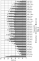
- Figure 8 provides an illustration of the noise reduction properties of an air exhaust treatment module assembly 10 similar to the arrangements described above but without using the reactive acoustic absorption structures of the second portions 22, containing the MPPs 28, 61, 63 and resonator cavities 29, 62.
- the higher of the three columns for each noise spectrum band represents noise levels at the rotor / generator source (i.e. upstream of the silencer); the next lower column for each noise spectrum band represents noise levels at the downstream end of the silencer / air exhaust treatment module.
- the lowest column for each noise spectrum band represents noise levels at the louvres.
- the reactive acoustic absorbers i.e. the second portions 22 of the sound absorbing columns 20 comprising the MPPs 28, 61, 63 and the resonator cavities 29, 62 can be optimally designed to attenuate the 100 Hz and 125 Hz centre band frequencies (or other target bands according to generator / rotor design and frequency of rotation), and the overall acoustic performance of the silencer assembly is thereby substantially improved without substantially affecting air flow.
- the microperforated panels 28, 61, 63 each comprise a thin plate, shell, or membrane with many holes therein. No resistive porous material is required in the resonator cavity 29, 62.
- the principal absorption mechanism may be provided by the resistance offered by the viscous losses in the holes of the panels 28, 61, 63 as the air molecules move back and forth under the influence of the sound pressure.
- the air co-vibrates as a mass in the numerous adjacent holes, with the air in the intermediate space between the absorber and a usually rigid rear wall acting as a spring similar to a Helmholtz resonator.
- the MPP and the material defining the cavity can be formed from any suitable material having the requisite stiffness to impart the required acoustic chamber properties.
- the walls of the resonator cavity 29, 62 are formed of stainless steel of thickness between 1.2 and 3 mm thick providing the required stiffness.
- the perforated panels 28, 61, 63 can be designed to optimise the acoustic absorption of the exhaust air treatment module 10.
- Pore diameters may be provided of the order of millimetres or even centimetres with little acoustic resistance and high reactance, or may be sub-millimetre in size providing high acoustic resistance.
- hole diameters are selected such that they are in the same order of magnitude as the acoustic boundary layer of a steady flow in the holes which allows for optimum damping of the resonance-amplified vibrations in the holes.
- the geometric parameter that is most instrumental in tuning the performance of the MPP is the resonator cavity depth which controls the air molecule velocity in the holes.
- the MPP absorbers are most effective when the particle velocity is high because this maximises the viscous friction in the holes.
- the sound absorption of the MPP absorber is dominated by the resonance of the air mass vibration, in both the perforated holes and the backing cavity, it is limited to the resonance frequency region; therefore its bandwidth can be relatively narrow.
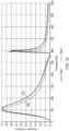
- a typical harmonic analysis of a normal incidence sound absorption coefficient for a MPP absorber is shown in figure 9 .
- the MPP 28 has perforation holes of diameter 0.8 mm, MPP panel thickness of 1.5 mm, perforation ratio (ratio of total area of holes to total plate area of 0.4%, and resonator cavity depth of 300 mm.
- a peak absorption can be engineered at approximately 100 Hz or 120 Hz, thereby being optimised for international operational requirements for generators that deliver AC power at 50 Hz or 60 Hz.
- a peak absorption could also be engineered at any suitable frequency of the rotating electrical machine, e.g. peak absorption at the electrical supply frequency of the rotor or harmonic thereof.
- MPP absorbers Two further potential MPP absorbers were designed, predicted to have high normal incident sound absorption coefficients at 100 Hz and 120 Hz. The dimensions of the two MPPs are given below. Type Hole diameter (mm) Panel thickness (mm) Perforation ratio (%) 1 0.9 0.8 0.25 2 1.0 1.0 0.21
- the resonator cavity 29, 62 may be divided into plural compartments transverse to the silencer air flow direction, with partitions 65 spaced along the width of the cavity (e.g. partitions that are orthogonal to the plane of the MPP 28, 61). Sound absorption of grazing waves (waves propagating parallel to the MPP 28, 61) may be less effective if the resonator cavity 29, 62 is not partitioned. However, waves that propagate normal to the MPP are attenuated equally without a partitioned cavity. Studies indicate that partitioning the cavity disrupts wave propagation behind the MPP 28, 61 and forces the MPP to behave like a traditional locally reacting absorber. Preferably, the spacing between adjacent partitions 65 should minimally be less than a half acoustic wavelength.
- An example design has partitions of width 300 mm.
- the acoustic pressure wave should propagate normal to the MPP and hence partitioning may not be required.
- the backing cavity was partitioned into five separate cavities 62a, 62b ... 62e as shown in figure 6 . This has an added benefit of stiffening the structure, particularly where the width of the structure extends along a substantial part of the axial length of the generator as depicted in figure 1 .
- separate reduced-width acoustic splitters 11 could be deployed side-by-side along the axial length of the generator.
- further improvement in noise reduction may be achieved by adjusting the spacing 30 between the first portion 21 and the second portion 22 of the sound absorbing columns 20.
- the highest noise reduction was found to be achieved with a 25 mm spacing between the first portion 21 and the second portion 22.
- the spacing between the first portion 21 and second portion 22 (and between the second portion 22 and the third portion 23 where applicable) may be maintained by the first, second and third portions being bolted to a support frame, not shown.
- two or even more reactive absorbers may be provided by the second portion 22 of the sound absorbing columns 20, the reactive absorbers being arranged in series in the air flow direction.
- lower second portion 22 may be configured as an MPP absorber tuned for attenuation at a first frequency, e.g. 50 Hz or 100 Hz
- an upper second portion 22a may be configured as an MPP absorber tuned for attenuation at a second frequency, e.g. 60 Hz or 120 Hz.
- the depth dimension for the cavities that provide optimal noise reduction at 100 Hz and 120 Hz, for both types of MPP absorber were found to be 260 mm for an upstream cavity and 300 mm for a downstream cavity.
- the MPP absorber boxes 22 should preferably be of stiff enough mechanical construction to not bend or flex during operation, and should preferably be mechanically isolated from the outlet silencer housing to avoid picking up any vibrations from the housing itself.
- predicted normal incidence absorption coefficients of the two types of MPP may have a relatively narrow absorption bandwidth, and this may result in less optimal noise reduction at 200 Hz and 240 Hz, and potentially at higher frequencies.
- the absorption bandwidth of the MPP may be improved by using a dual MPP layer arrangement as illustrated in figure 6 and figure 11 .
- a cavity 120 with multiple channels or ducts 121, 122, 123 is another method for improving the bandwidth.
- the depths of the individual channels can be tuned to attenuate a particular frequency, with increased channel depth providing lower frequency absorption; hence more broadband frequency absorption is achieved.
- the resonator cavity may be divided into plural compartments 121, 122, 123 having different depths D1, D2, D3.
- the described embodiments exemplify a silencer which is particularly tuned to absorb aero-acoustic noise from ventilation slots on a rotor of a generator, it will be understood that the silencer can be adapted to provide acoustic attenuation in respect of any feature of a rotating electrical machine which has a tendency to generate periodic air movements as a result of the rotation.
Landscapes
- Engineering & Computer Science (AREA)
- Power Engineering (AREA)
- Physics & Mathematics (AREA)
- Acoustics & Sound (AREA)
- Multimedia (AREA)
- Chemical & Material Sciences (AREA)
- Combustion & Propulsion (AREA)
- Mechanical Engineering (AREA)
- General Engineering & Computer Science (AREA)
- Motor Or Generator Frames (AREA)
- Soundproofing, Sound Blocking, And Sound Damping (AREA)
- Motor Or Generator Cooling System (AREA)
Description
- The present disclosure relates to sound absorbing structures used in air exhaust pathways for electrical generators, electric motors and other rotating electrical machines.
- The control of noise emissions from large rotating electrical machines is often important in the design and implementation of such equipment. Along with well-known vibration-induced noise, there can be significant aerodynamic noise arising from air flows generated by the rapid rotation of components of the rotating electrical machine. The expression 'rotating electrical machine' is intended to encompass all electrical machines having a rotor component that is ventilated by air flows and/or which generates such airflows during rotation.
- The present invention is directed towards mitigating the effects of aerodynamic noise from such machines.
-
US 5453647 discloses an air-ventilated electric motor including a motor housing having a cooling-air inlet and a cooling-air outlet. An outlet muffler array is located outside, and spaced apart from, the motor housing and includes two or more outlet mufflers each having a fluid entrance and a fluid exit. An outlet connecting duct has a first end connected to the cooling-air outlet of the motor housing and has a second end connected in parallel to the fluid entrances of each of the outlet mufflers. The assembly also includes an inlet muffler array and an inlet connecting duct.JP 2001222065A RU 2494266C2 JP 2001092468A - The present invention comprises a rotating electrical machine and method as defined in the claims. Embodiments that do not fall within the scope of the claims are to be interpreted as examples useful for understanding the invention.
- Embodiments of the present invention will now be described by way of example and with reference to the accompanying drawings in which:
-
Figure 1A shows a schematic cross-sectional side view of an electrical generator showing the positioning of a silencer unit within the generator housing; -
Figure 1B shows a schematic cross-sectional end view of the electrical generator offigure 1A ; -
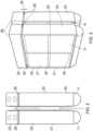
Figure 2 is an end view of two sound absorbing columns used in the generator housing offigures 1A and 1B ; -
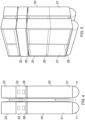
Figure 3 is a perspective view of the two sound absorbing columns offigure 2 ;Figure 4 is an end view of two alternative sound absorbing columns used in the generator housing offigures 1A and 1B ; -
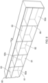
Figure 5 is a perspective view of the two sound absorbing columns offigure 4 ;Figure 6 is a perspective view of a reactive sound absorbing unit usable in the columns offigures 2 to 5 ; -
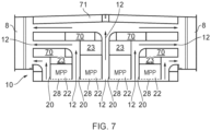
Figure 7 is a schematic cross-sectional end view of a top portion of the silencer unit offigure 1B ; -
Figure 8 is a graph showing a noise reduction spectrum of a silencer unit for use with the generator offigures 1A and 1B , using only resistive sound absorbing structures; -
Figure 9 is a graph showing a calculated normal incidence sound absorption coefficient spectrum for a plane wave striking a reactive sound absorbing unit for use in the sound absorbing columns offigures 3 to 5 ; -
Figure 10 is a graph showing a predicted normal incidence sound absorption coefficient spectra for plane waves striking two different reactive sound absorbing units for use in the sound absorbing columns offigures 3 to 5 ; -
Figure 11 is a schematic cross-sectional end view of an alternative, dual panel, reactive sound absorbing unit for use in the sound absorbing columns offigures 3 to 5 ; -
Figure 12 is a schematic cross-sectional end view of an alternative, three-channel, reactive sound absorbing unit for use in the sound absorbing columns offigures 3 to 5 ; and -
Figure 13 is a graph showing predicted normal incidence sound absorption coefficient spectra for plane waves striking the reactive sound absorbing units offigures 11 and 12 . - Throughout the present specification, the descriptors relating to relative orientation and position, such as "top", "bottom", "horizontal", "vertical", "left", "right", "up", "down", "front", "back", as well as any adjective and adverb derivatives thereof, are used in the sense of the orientation of the apparatus as presented in the drawings in a conventional mode of use. However, such descriptors are not intended to be in any way limiting to an intended use of the described or claimed invention.
-
Figure 1A shows a schematic diagram of anelectrical generator 1 within agenerator housing 2. Thegenerator 1 has arotation axis 3 extending longitudinally through thehousing 2 as seen in the side view offigure 1A . The lower part 4 of thehousing 2 provides an enclosure for thegenerator 1 and associated equipment, which may be more generally referred to herein as a rotor housing. Theupper part 5 of thehousing 2 providesair inlet structures 6, an air outlet structure /silencer 7 which includes an air exhaust treatment module 10 (figure 1B ), andair outlet louvres 8 for exhausting air from thehousing 2. This is best seen in the axial cross-sectional view offigure 1B . - Ventilation / cooling air is provided to the axial ends of the
generator 1 from theair inlet structures 6 and is conveyed axially along ventilation slots in the rotor 9 of thegenerator 1. From the ventilation slots of the rotor the air is ejected under rotational motion of the rotor, and passes through thesilencer 7 /exhaust treatment module 10 and through theoutlet louvres 8. - In a rotating electrical machine such as the
electrical generator 1, aero-acoustic noise is generated at least in part due to the high velocity air jets exiting the rotor ventilation slots. The aero-acoustic noise may have a strong low frequency component, and can be particularly severe at twice the operating frequency of the generator. There may also be higher order harmonics related to the number and spacing of the rotor ventilation slots. In the airexhaust treatment module 10, this noise is attenuated by dissipative silencers, comprisingacoustic splitters 11. As seen infigure 1B , a number ofacoustic splitters 11 extend upwardly from the lower part 4 of thegenerator housing 2 towards the top of the exhaustair treatment module 10 where theoutlet louvres 8 are situated. Theacoustic splitters 11 define exhaustair flow pathways 12 in the spaces between them, which direct the exhaust air to thelouvres 8. Theacoustic splitters 11 comprise multiple portions in each column, the characteristics of which are described below. - The
acoustic splitters 11 are shown in more detail infigure 2 . Each acoustic splitter comprises asound absorbing column 20 having afirst portion 21 closest to the rotor /generator 1 and asecond portion 22 further away from the rotor /generator 1. Thefirst portion 21 is in an "upstream" position, i.e. closer to the noise source / air source / rotor, and thesecond portion 22 is in a "downstream" position, i.e. away from the noise source / air source / rotor. - The
first portion 21 contains a first sound absorbing material, which is preferably a porous absorber such as foam or Rockwool. Thefirst portion 21 of thesound absorbing column 20 may comprise a frame havingrigid sides 24,structural supports 26 such as crossmembers, and aface 27 adjacent to theair flow path 12 which exposes the sound absorbing material to theair flow path 12. Theface 27 may comprise an open mesh barrier or perforated panel to retain the porous absorber in place within the frame of thefirst portion 21 of the sound absorbing column and to allow air movement into and out of the structure. The mesh may comprise a metal lattice structure for example. Alternatively, theface 27 could comprise a solid material allowing sound energy to pass therethrough to the porous absorber. In a general aspect, thefirst portion 21 comprises a resistive acoustic absorber or resistive sound absorbing unit. - The
second portion 22 comprises a microperforated panel (MPP) 28 adjacent to the top (i.e. the downstream end) of thefirst portion 21, and aresonator cavity 29 downstream of theMPP 28. Thesecond portion 22 effectively provides a reactive acoustic absorber or reactive sound absorbing unit. As such, thesecond portion 22 need not contain a porous sound absorber material, such as foam or Rockwool. - Referring also to
figures 4 and 5 , thesound absorbing columns 20 may include athird portion 23 above, i.e. downstream of, thesecond portion 22. Thethird portion 23 may comprise a further resistive acoustic absorber structure similar to thefirst portion 21. - Two or more
sound absorbing columns 20 may define multipleair flow paths 12 each extending along the axial length of the rotor / generator. The example offigure 1B andfigure 7 comprises foursound absorbing columns 20 which split the airflow into fiveair flow paths 12. - With reference to
figure 6 , thesecond portion 22 may comprise more than oneMPP 28. In the example shown infigure 6 , thesecond portion 60 comprises afirst MPP 61 adjacent to the downstream end of thefirst portion 21, aresonator cavity 62 downstream of thefirst MPP 61, and asecond MPP 63 downstream of thefirst MPP 61 dividing theresonator cavity 62 into two parts. This arrangement will be discussed in more detail later. - In a general aspect, the first portion 21 (resistive sound absorbing unit) of the
sound absorbing column 20 may therefore lie between the rotor /generator 1 and the second portion 22 (reactive sound absorbing unit) of thesound absorbing column 20. Thesecond portion 22 of thesound absorbing column 20 may lie between thefirst portion 21 and thethird portion 23. - The microperforated panel or
panels air outlet structure 7 for the particular application, e.g. the particular rotating electrical machine in use. The silencer structure is preferably tuned for a broad peak absorption between 80 and 180 Hz, or more particularly may be tuned for a peak absorption between 100 and 120 Hz, or at one of those frequencies. Using dualmicroperforated panels figure 6 may provide a broader peak absorption between 60 and 300 Hz or more particularly may be tuned for a peak absorption between 100 and 120 Hz. - The integration of the
second portion 22 into asound absorbing column 20, thereby defining aresonator cavity 62 and theMPP air treatment assembly 10 to absorb the aero-acoustic noise caused by the high velocity air jets exiting the rotor ventilation slots which have a strong low frequency component, particularly severe at twice the operating frequency of the generator. The higher order harmonics related to the number and spacing of the ventilation slots on the rotor are more effectively attenuated by the dissipative resistive silencers of the first and (optional)third portions - Tests have shown that the first and
third portions outlet louvres 8. -
Figure 7 shows a possible arrangement for the upper part of the airexhaust treatment module 10. In this arrangement, some or each of thesound absorbing columns 20 with the first portion 21 (not visible), thesecond portion 22 comprising the MPP 28 (orMPP 61, 63) and theresonator cavity 62, and thethird portion 23, may further include a transversefourth portion 70 to direct the air flows inair flow paths 12 laterally outward to thelouvres 8. The transversefourth portions 70 may incorporate more of the first sound absorbing material, preferably a porous absorber such as foam or Rockwool. Further resistive absorbingmaterial 71 may be provided on the roof of theupper part 5 of thehousing 2. -
Figure 8 provides an illustration of the noise reduction properties of an air exhausttreatment module assembly 10 similar to the arrangements described above but without using the reactive acoustic absorption structures of thesecond portions 22, containing theMPPs resonator cavities - The reactive acoustic absorbers, i.e. the
second portions 22 of thesound absorbing columns 20 comprising the MPPs 28, 61, 63 and theresonator cavities - The
microperforated panels resonator cavity panels MPP resonator cavity - The
perforated panels air treatment module 10. Pore diameters may be provided of the order of millimetres or even centimetres with little acoustic resistance and high reactance, or may be sub-millimetre in size providing high acoustic resistance. Preferably, hole diameters are selected such that they are in the same order of magnitude as the acoustic boundary layer of a steady flow in the holes which allows for optimum damping of the resonance-amplified vibrations in the holes. - The geometric parameter that is most instrumental in tuning the performance of the MPP is the resonator cavity depth which controls the air molecule velocity in the holes. The MPP absorbers are most effective when the particle velocity is high because this maximises the viscous friction in the holes. As the sound absorption of the MPP absorber is dominated by the resonance of the air mass vibration, in both the perforated holes and the backing cavity, it is limited to the resonance frequency region; therefore its bandwidth can be relatively narrow.
- A typical harmonic analysis of a normal incidence sound absorption coefficient for a MPP absorber is shown in
figure 9 . For this absorber, theMPP 28 has perforation holes of diameter 0.8 mm, MPP panel thickness of 1.5 mm, perforation ratio (ratio of total area of holes to total plate area of 0.4%, and resonator cavity depth of 300 mm. A peak absorption can be engineered at approximately 100 Hz or 120 Hz, thereby being optimised for international operational requirements for generators that deliver AC power at 50 Hz or 60 Hz. A peak absorption could also be engineered at any suitable frequency of the rotating electrical machine, e.g. peak absorption at the electrical supply frequency of the rotor or harmonic thereof. - Two further potential MPP absorbers were designed, predicted to have high normal incident sound absorption coefficients at 100 Hz and 120 Hz. The dimensions of the two MPPs are given below.
Type Hole diameter (mm) Panel thickness (mm) Perforation ratio (%) 1 0.9 0.8 0.25 2 1.0 1.0 0.21 - The predicted normal incidence sound absorption coefficients for the two types of MPP absorbers, both with a cavity depth of 300 mm, are shown in
Figure 10 , withtype 1 providingtrace 101 andtype 2 providingtrace 102. - With further reference to
figure 6 , theresonator cavity partitions 65 spaced along the width of the cavity (e.g. partitions that are orthogonal to the plane of theMPP 28, 61). Sound absorption of grazing waves (waves propagating parallel to theMPP 28, 61) may be less effective if theresonator cavity MPP adjacent partitions 65 should minimally be less than a half acoustic wavelength. An example design has partitions ofwidth 300 mm. - In the illustrated arrangements, the acoustic pressure wave should propagate normal to the MPP and hence partitioning may not be required. However, to remove any potential risk of performance deterioration due to random / grazing incident acoustic waves, the backing cavity was partitioned into five
separate cavities figure 6 . This has an added benefit of stiffening the structure, particularly where the width of the structure extends along a substantial part of the axial length of the generator as depicted infigure 1 . In an alternative configuration, separate reduced-widthacoustic splitters 11 could be deployed side-by-side along the axial length of the generator. - Referring again to
figure 3 , further improvement in noise reduction may be achieved by adjusting the spacing 30 between thefirst portion 21 and thesecond portion 22 of thesound absorbing columns 20. In a preferred arrangement, the highest noise reduction was found to be achieved with a 25 mm spacing between thefirst portion 21 and thesecond portion 22. The spacing between thefirst portion 21 and second portion 22 (and between thesecond portion 22 and thethird portion 23 where applicable) may be maintained by the first, second and third portions being bolted to a support frame, not shown. - In general, two or even more reactive absorbers may be provided by the
second portion 22 of thesound absorbing columns 20, the reactive absorbers being arranged in series in the air flow direction. For example, with reference tofigure 2 , lowersecond portion 22 may be configured as an MPP absorber tuned for attenuation at a first frequency, e.g. 50 Hz or 100 Hz, and an uppersecond portion 22a may be configured as an MPP absorber tuned for attenuation at a second frequency, e.g. 60 Hz or 120 Hz. It has been found, however, that for frequencies of interest including 100 Hz and 120 Hz, and with cavity depths in the range 260-300 mm, most of the acoustic energy is absorbed by the first two MPP absorbers and the addition of further reactive absorbers after the second may not contribute significantly to additional noise reduction. Omitting further reactive absorbers may however, contribute to reduced air flow resistance and therefore reduce an expected pressure-drop across the exhaust treatment module. Thus, two series-mounted reactive absorbers may be an optimal number in many circumstances. - In the examples shown, the depth dimension for the cavities that provide optimal noise reduction at 100 Hz and 120 Hz, for both types of MPP absorber, were found to be 260 mm for an upstream cavity and 300 mm for a downstream cavity.
- Further refinements may be made to the silencer by taking into account the structural compliance of the walls of the MPP absorber cavity. The
MPP absorber boxes 22 should preferably be of stiff enough mechanical construction to not bend or flex during operation, and should preferably be mechanically isolated from the outlet silencer housing to avoid picking up any vibrations from the housing itself. - As seen in
figure 10 , predicted normal incidence absorption coefficients of the two types of MPP (defined above astype 1 and type 2) may have a relatively narrow absorption bandwidth, and this may result in less optimal noise reduction at 200 Hz and 240 Hz, and potentially at higher frequencies. The absorption bandwidth of the MPP may be improved by using a dual MPP layer arrangement as illustrated infigure 6 andfigure 11 . - With reference to
figures 11 and 13 , predicted normal incidence sound absorption coefficients for a two-layer MPP absorber as seen infigure 11 , having MPP hole diameters = 0.3 mm, MPP thickness = 1 mm, perforation ratio = 1.5%, and with the two plates spaced 50 mm apart (D1) in a cavity ofdepth 300 mm (D2) provides anabsorption coefficient spectrum 130 as shown infigure 13 . - Another method for improving the bandwidth is the use of a
cavity 120 with multiple channels orducts figure 12 . The depths of the individual channels can be tuned to attenuate a particular frequency, with increased channel depth providing lower frequency absorption; hence more broadband frequency absorption is achieved. The normal incidence sound absorption coefficient for a MPP with hole diameters 0.3 mm, MPP thickness = 1 mm, perforation ratio = 1.5%, and with first cavity depth D1 = 150 mm; second cavity depth D2 = 225 mm and third cavity depth D3 = 300 mm provides anabsorption coefficient spectrum 131 as shown infigure 13 . Thus, in a general aspect, the resonator cavity may be divided intoplural compartments - Although the described embodiments exemplify a silencer which is particularly tuned to absorb aero-acoustic noise from ventilation slots on a rotor of a generator, it will be understood that the silencer can be adapted to provide acoustic attenuation in respect of any feature of a rotating electrical machine which has a tendency to generate periodic air movements as a result of the rotation.
- Other embodiments are intentionally within the scope of the accompanying claims.
Claims (15)
- A rotating electrical machine (1) comprising:a housing (2) having a first part (4) providing an enclosure for a rotor (9) therein and a second part (5) providing an enclosure for a silencer (7) therein;an air flow path (12) passing from the first part (4) of the housing (2) to and through the silencer (7) to an exhaust (8),the silencer (7) comprising a part of the air flow path (12) disposed adjacent at least one sound absorbing column (20), the at least one sound absorbing column (20) comprising a first portion (21) closest to the rotor (9) having a first, porous, sound absorbing material therein and a second portion (22) further from the rotor (9), the second portion (22) having a microperforated panel (MPP) (28) adjacent to a downstream end of the first portion (21) and a resonator cavity (29, 62, 120) downstream of the MPP (28), the air flow path extending along the axial length of the rotor (9) and passing along the first portion (21), the MPP and then the resonator cavity (29, 62, 120) of the at least one sound absorbing column (20) in a direction away from the rotor axis.
- The rotating electrical machine of claim 1 in which the silencer (7) comprises at least two of said sound absorbing columns (20) and the at least one air flow path (12) is defined between two of the sound absorbing columns.
- The rotating electrical machine of claim 1 in which the sound absorbing column (20) further includes a third portion (23) having sound absorbing material therein.
- The rotating electrical machine of claim 1 having a second MPP (28) in the resonator cavity (29, 62, 120).
- The rotating electrical machine of claim 1 in which the resonator cavity (62) is divided into plural compartments (62a - 62e) transverse to the direction of the air flow path past the column (20).
- The rotating electrical machine of claim 1 in which the resonator cavity (62, 120) is divided into plural compartments (121, 122, 123) having different depths.
- The rotating electrical machine of claim 1 in which the second portion (22) of the column (20) is tuned for a peak absorption between 80 and 180 Hz, or more particularly between 100 and 120 Hz.
- The rotating electrical machine of claim 4 in which the second portion (22) of the column (20) is tuned for a peak absorption between 60 and 300 Hz, or more particularly between 100 and 120 Hz.
- The rotating electrical machine of claim 1 in which the second portion (22) of the column (20) is tuned for a peak absorption at the electrical supply frequency of the rotor or harmonic thereof.
- The rotating electrical machine of claim 1 in which the first sound absorbing material is a porous absorber or foam or a fibrous mineral wool.
- The rotating electrical machine of claim 1 in which the rotating electrical machine is a generator (1).
- The rotating electrical machine of claim 2 having multiple sound absorbing columns (20) defining multiple air flow paths (12) each having an elongate cross-sectional profile extending along the axial length of the rotor (9).
- The rotating electrical machine of claim 1 in which the MPP (28) comprises:perforations of diameter in the range 0.5 mm to 1.2 mm; ora plate of thickness 0.5 mm to 2.5 mm; ora plate in which the ratio of total area of perforations to total plate area lies in the range 0.15% to 0.4%.
- The rotating electrical machine of claim 1 in which the resonator cavity (29, 62, 120) has a depth in the range 150 mm to 400 mm, or 200 mm to 400 mm.
- A method of controlling aerodynamic noise emissions from a ventilation path of a rotating electrical machine (1) disposed within a housing (2), the method comprising:disposing a rotor (9) within a first part (4) of the housing (2);disposing a silencer (7) within a second part (5) of the housing (2),providing an air flow path (12) passing from the first part (4) of the housing (2) to and through the silencer (7) to an exhaust (8) of the generator housing (2),providing the silencer (7) with a part of the air flow path (12) disposed adjacent at least one sound absorbing column (20), the at least one sound absorbing column (20) comprising a first portion (21) closest to the rotor (9) having a first, porous, sound absorbing material therein and a second portion (22) further from the rotor (9), the second portion (22) having a microperforated panel (MPP) (28) adjacent to a downstream end of the first portion (21) and a resonator cavity (29, 62, 120) downstream of the MPP (28), the air flow path extending along the axial length of the rotor (9) and passing along the first portion (21), the MPP and then the resonator cavity (29, 62, 120) of the at least one sound absorbing column (20) in a direction away from the rotor axis,passing cooling air along the at least one air flow path (12) past the first portion (21) of the sound absorbing column (20) such that the first, porous, sound absorbing material acts as a resistive acoustic absorber, andpassing cooling air along the at least one air flow path (12) past the second portion (22) of the sound absorbing column (20) such that the microperforated panel (MPP) (28) and the resonator cavity (29, 62, 120) act as a reactive sound absorber.
Applications Claiming Priority (2)
| Application Number | Priority Date | Filing Date | Title |
|---|---|---|---|
| GB1718127.2A GB2568055B (en) | 2017-11-02 | 2017-11-02 | Air outlet sound absorber for a rotating electrical machine |
| PCT/GB2018/053166 WO2019086879A1 (en) | 2017-11-02 | 2018-11-01 | Air outlet sound absorber for a rotating electrical machine |
Publications (2)
| Publication Number | Publication Date |
|---|---|
| EP3704784A1 EP3704784A1 (en) | 2020-09-09 |
| EP3704784B1 true EP3704784B1 (en) | 2024-08-28 |
Family
ID=60664713
Family Applications (1)
| Application Number | Title | Priority Date | Filing Date |
|---|---|---|---|
| EP18800289.3A Active EP3704784B1 (en) | 2017-11-02 | 2018-11-01 | Air outlet sound absorber for a rotating electrical machine |
Country Status (8)
| Country | Link |
|---|---|
| US (1) | US11715992B2 (en) |
| EP (1) | EP3704784B1 (en) |
| JP (1) | JP7319284B2 (en) |
| CN (1) | CN111373638B (en) |
| BR (1) | BR112020008789B1 (en) |
| ES (1) | ES2991422T3 (en) |
| GB (1) | GB2568055B (en) |
| WO (1) | WO2019086879A1 (en) |
Families Citing this family (3)
| Publication number | Priority date | Publication date | Assignee | Title |
|---|---|---|---|---|
| CA3039493C (en) * | 2016-10-05 | 2024-10-29 | Bombardier Inc. | Noise reducing air duct |
| JP7610995B2 (en) * | 2021-02-03 | 2025-01-09 | 三菱重工業株式会社 | Silencer |
| CN116168672A (en) * | 2021-11-25 | 2023-05-26 | 中兴智能科技南京有限公司 | A muffler, muffler and information communication system |
Family Cites Families (37)
| Publication number | Priority date | Publication date | Assignee | Title |
|---|---|---|---|---|
| US2989136A (en) * | 1959-04-14 | 1961-06-20 | Wohlberg George | Sound attenuation |
| US4150313A (en) * | 1977-07-15 | 1979-04-17 | Lord Corporation | Silencer for an internally-ventilated electric motor |
| IT1118938B (en) * | 1979-10-05 | 1986-03-03 | Fiat Ricerche | VENTILATION SHUTTER INCLUDING A PLURALITY OF PROFILED BLINDS |
| US4266602A (en) * | 1980-02-21 | 1981-05-12 | Westinghouse Electric Corp. | Heat exchanger for cooling electrical power apparatus |
| JPS573363U (en) * | 1980-06-05 | 1982-01-08 | ||
| JPS6096972U (en) * | 1983-12-05 | 1985-07-02 | 株式会社東芝 | Filter for inverter-driven rotating electric machines |
| JPS62217833A (en) * | 1986-03-18 | 1987-09-25 | Toshiba Corp | Muffling device of rotary electric machine |
| JPH02102313A (en) * | 1988-10-11 | 1990-04-13 | Sankyo Kogyo Kk | Muffling device for chamber |
| AU5889790A (en) * | 1989-12-04 | 1991-06-06 | General Electric Company | Integral silencer for electric motors |
| FI95747B (en) * | 1991-01-17 | 1995-11-30 | Valmet Paper Machinery Inc | Mufflers for low frequencies for air ducts in paper mills |
| US5728979A (en) * | 1993-04-05 | 1998-03-17 | Air Handling Engineering Ltd. | Air handling structure for fan inlet and outlet |
| CA2104991C (en) * | 1993-08-27 | 1996-09-10 | Nestor Ewanek | Sound reduction unit for compressors |
| JPH0791727A (en) * | 1993-09-17 | 1995-04-04 | Hitachi Air Conditioning & Refrig Co Ltd | Muffling chamber |
| US5473124A (en) * | 1994-01-31 | 1995-12-05 | Dipti Datta | Packless silencer |
| US5453647A (en) * | 1994-06-27 | 1995-09-26 | General Electric Company | Electric motor assembly with muffler bank |
| CA2164370A1 (en) * | 1995-12-04 | 1997-06-05 | Donald L. Allen | Reactive acoustic silencer |
| JP3532813B2 (en) * | 1999-04-08 | 2004-05-31 | 株式会社日本自動車部品総合研究所 | Sound insulation wall design method and sound insulation wall |
| US6342005B1 (en) * | 1999-09-30 | 2002-01-29 | Carrier Corporation | Active noise control for plug fan installations |
| US6402612B2 (en) * | 2000-01-27 | 2002-06-11 | Air Handling Engineering Ltd. | Column fan unit |
| JP2001222065A (en) | 2000-02-07 | 2001-08-17 | Sanyo Electric Co Ltd | Electronic apparatus having cooling fan |
| JP2003050586A (en) | 2000-09-29 | 2003-02-21 | Kobe Steel Ltd | Porous soundproof structure and method of manufacturing the same |
| US6537490B2 (en) * | 2001-05-30 | 2003-03-25 | M & I Heat Transfer Products Ltd. | Air inlet and outlet silencer structures for turbine |
| JP2003108148A (en) * | 2001-09-27 | 2003-04-11 | Eico Systems Kk | Power generating device and sound absorbing method for sound generated in the power generating device |
| US6851514B2 (en) * | 2002-04-15 | 2005-02-08 | Air Handling Engineering Ltd. | Outlet silencer and heat recovery structures for gas turbine |
| US6799657B2 (en) * | 2002-10-02 | 2004-10-05 | Carrier Corporation | Absorptive/reactive muffler for variable speed compressors |
| JP4215790B2 (en) * | 2006-08-29 | 2009-01-28 | Necディスプレイソリューションズ株式会社 | Silencer, electronic device, and method for controlling silencing characteristics |
| US7717229B2 (en) * | 2008-05-09 | 2010-05-18 | Siemens Energy, Inc. | Gas turbine exhaust sound suppressor and associated methods |
| CN201266868Y (en) * | 2008-08-15 | 2009-07-01 | 上海恒锦动力科技有限公司 | Impedance composite type noise reducer |
| KR100924958B1 (en) * | 2009-06-04 | 2009-11-06 | 한국방진방음 주식회사 | Air Conditioning Duct Silencer with Resonant Splitter |
| KR101030440B1 (en) * | 2009-06-15 | 2011-04-25 | (주)엔에스브이 | Sound absorption expansion type duct silencer where sound is absorbed by sound absorption and expansion |
| US8240429B1 (en) * | 2011-02-21 | 2012-08-14 | Siemens Industry, Inc. | System method and devices for windage noise damping in induction motor |
| RU2494266C2 (en) | 2011-09-19 | 2013-09-27 | Федеральное государственное бюджетное образовательное учреждение высшего профессионального образования "Тольяттинский государственный университет" | Noise silencer (versions) |
| GB2528950A (en) * | 2014-08-06 | 2016-02-10 | Aaf Ltd | Sound suppression apparatus |
| EP3192068A1 (en) * | 2014-09-09 | 2017-07-19 | 3M Innovative Properties Company | Acoustic device |
| US9890713B2 (en) * | 2015-03-04 | 2018-02-13 | General Electric Company | Heavy duty gas turbine inlet system |
| US10119469B2 (en) * | 2016-09-15 | 2018-11-06 | General Electric Company | Method and apparatus for modularized inlet silencer baffles |
| CN108458467B (en) * | 2017-02-17 | 2020-11-10 | S.I.Pan公司 | Separator and muffler including the same |
-
2017
- 2017-11-02 GB GB1718127.2A patent/GB2568055B/en active Active
-
2018
- 2018-11-01 CN CN201880075265.4A patent/CN111373638B/en active Active
- 2018-11-01 ES ES18800289T patent/ES2991422T3/en active Active
- 2018-11-01 EP EP18800289.3A patent/EP3704784B1/en active Active
- 2018-11-01 US US16/761,036 patent/US11715992B2/en active Active
- 2018-11-01 BR BR112020008789-0A patent/BR112020008789B1/en active IP Right Grant
- 2018-11-01 WO PCT/GB2018/053166 patent/WO2019086879A1/en not_active Ceased
- 2018-11-01 JP JP2020544169A patent/JP7319284B2/en active Active
Also Published As
| Publication number | Publication date |
|---|---|
| CN111373638A (en) | 2020-07-03 |
| BR112020008789A2 (en) | 2020-10-20 |
| RU2020117014A (en) | 2021-12-02 |
| CN111373638B (en) | 2022-09-09 |
| JP2021501919A (en) | 2021-01-21 |
| EP3704784A1 (en) | 2020-09-09 |
| BR112020008789B1 (en) | 2024-02-27 |
| US11715992B2 (en) | 2023-08-01 |
| RU2020117014A3 (en) | 2022-04-27 |
| GB2568055A (en) | 2019-05-08 |
| US20210180487A1 (en) | 2021-06-17 |
| GB201718127D0 (en) | 2017-12-20 |
| JP7319284B2 (en) | 2023-08-01 |
| GB2568055B (en) | 2023-02-01 |
| ES2991422T3 (en) | 2024-12-03 |
| WO2019086879A1 (en) | 2019-05-09 |
Similar Documents
| Publication | Publication Date | Title |
|---|---|---|
| US8240429B1 (en) | System method and devices for windage noise damping in induction motor | |
| US5625172A (en) | Engine enclosure air inlet/discharge sound attenuator | |
| US9253556B1 (en) | Dissipative system for increasing audio entropy thereby diminishing auditory perception | |
| US20170261226A1 (en) | Acoustic metamaterial noise control method and apparatus for ducted systems | |
| US11715992B2 (en) | Air outlet sound absorber for a rotating electrical machine | |
| US4516657A (en) | Sound suppression of engine noise | |
| EP3646316A1 (en) | Microperforated conduit | |
| KR100879887B1 (en) | Sound absorption and resonance acoustic baffle for reducing transformer noise and its installation method | |
| CN211666948U (en) | Air duct silencing structure and electrical cabinet | |
| US5453647A (en) | Electric motor assembly with muffler bank | |
| EP3153681B1 (en) | Noise baffle | |
| RU2310024C2 (en) | Guard for textile machine spindles | |
| WO1993004272A1 (en) | Noise suppression enclosure for an engine | |
| CN113123875B (en) | Aeroengine sound absorption device and aeroengine | |
| JP3580810B1 (en) | Sound absorbing device for very low frequency sound | |
| RU2847371C2 (en) | Sound absorber for the exhaust air duct of a rotary electric machine | |
| JP3340855B2 (en) | Silencer | |
| RU2775287C2 (en) | Sound absorber of exhaust duct for rotating electric machine | |
| CN112177982A (en) | Noise reduction air duct and gas water heater | |
| CN210343440U (en) | Sound-proof housing for turbonator | |
| CN116517887A (en) | Fan cluster pneumatic noise composite control device and control method | |
| JP2012145776A (en) | Acoustic property improving structure | |
| Grosveld et al. | Design of an acoustic muffler prototype for an air filtration system inlet on International Space Station | |
| JP2006207508A (en) | Fan noise reduction device and fan noise reduction method | |
| CN120183368A (en) | Noise reduction device and power equipment |
Legal Events
| Date | Code | Title | Description |
|---|---|---|---|
| STAA | Information on the status of an ep patent application or granted ep patent |
Free format text: STATUS: UNKNOWN |
|
| STAA | Information on the status of an ep patent application or granted ep patent |
Free format text: STATUS: THE INTERNATIONAL PUBLICATION HAS BEEN MADE |
|
| PUAI | Public reference made under article 153(3) epc to a published international application that has entered the european phase |
Free format text: ORIGINAL CODE: 0009012 |
|
| STAA | Information on the status of an ep patent application or granted ep patent |
Free format text: STATUS: REQUEST FOR EXAMINATION WAS MADE |
|
| 17P | Request for examination filed |
Effective date: 20200601 |
|
| AK | Designated contracting states |
Kind code of ref document: A1 Designated state(s): AL AT BE BG CH CY CZ DE DK EE ES FI FR GB GR HR HU IE IS IT LI LT LU LV MC MK MT NL NO PL PT RO RS SE SI SK SM TR |
|
| AX | Request for extension of the european patent |
Extension state: BA ME |
|
| DAV | Request for validation of the european patent (deleted) | ||
| DAX | Request for extension of the european patent (deleted) | ||
| STAA | Information on the status of an ep patent application or granted ep patent |
Free format text: STATUS: EXAMINATION IS IN PROGRESS |
|
| 17Q | First examination report despatched |
Effective date: 20210903 |
|
| P01 | Opt-out of the competence of the unified patent court (upc) registered |
Effective date: 20230526 |
|
| GRAP | Despatch of communication of intention to grant a patent |
Free format text: ORIGINAL CODE: EPIDOSNIGR1 |
|
| STAA | Information on the status of an ep patent application or granted ep patent |
Free format text: STATUS: GRANT OF PATENT IS INTENDED |
|
| INTG | Intention to grant announced |
Effective date: 20240415 |
|
| GRAS | Grant fee paid |
Free format text: ORIGINAL CODE: EPIDOSNIGR3 |
|
| GRAA | (expected) grant |
Free format text: ORIGINAL CODE: 0009210 |
|
| STAA | Information on the status of an ep patent application or granted ep patent |
Free format text: STATUS: THE PATENT HAS BEEN GRANTED |
|
| AK | Designated contracting states |
Kind code of ref document: B1 Designated state(s): AL AT BE BG CH CY CZ DE DK EE ES FI FR GB GR HR HU IE IS IT LI LT LU LV MC MK MT NL NO PL PT RO RS SE SI SK SM TR |
|
| RAP3 | Party data changed (applicant data changed or rights of an application transferred) |
Owner name: BRUSH ELECTRICAL MACHINES LIMITED |
|
| REG | Reference to a national code |
Ref country code: GB Ref legal event code: FG4D |
|
| REG | Reference to a national code |
Ref country code: CH Ref legal event code: EP |
|
| REG | Reference to a national code |
Ref country code: DE Ref legal event code: R096 Ref document number: 602018073689 Country of ref document: DE |
|
| REG | Reference to a national code |
Ref country code: IE Ref legal event code: FG4D Ref country code: NL Ref legal event code: FP |
|
| REG | Reference to a national code |
Ref country code: ES Ref legal event code: FG2A Ref document number: 2991422 Country of ref document: ES Kind code of ref document: T3 Effective date: 20241203 |
|
| REG | Reference to a national code |
Ref country code: LT Ref legal event code: MG9D |
|
| REG | Reference to a national code |
Ref country code: SK Ref legal event code: T3 Ref document number: E 45384 Country of ref document: SK Ref country code: AT Ref legal event code: MK05 Ref document number: 1719067 Country of ref document: AT Kind code of ref document: T Effective date: 20240828 |
|
| PG25 | Lapsed in a contracting state [announced via postgrant information from national office to epo] |
Ref country code: PT Free format text: LAPSE BECAUSE OF FAILURE TO SUBMIT A TRANSLATION OF THE DESCRIPTION OR TO PAY THE FEE WITHIN THE PRESCRIBED TIME-LIMIT Effective date: 20241230 Ref country code: GR Free format text: LAPSE BECAUSE OF FAILURE TO SUBMIT A TRANSLATION OF THE DESCRIPTION OR TO PAY THE FEE WITHIN THE PRESCRIBED TIME-LIMIT Effective date: 20241129 Ref country code: PL Free format text: LAPSE BECAUSE OF FAILURE TO SUBMIT A TRANSLATION OF THE DESCRIPTION OR TO PAY THE FEE WITHIN THE PRESCRIBED TIME-LIMIT Effective date: 20240828 Ref country code: FI Free format text: LAPSE BECAUSE OF FAILURE TO SUBMIT A TRANSLATION OF THE DESCRIPTION OR TO PAY THE FEE WITHIN THE PRESCRIBED TIME-LIMIT Effective date: 20240828 |
|
| PG25 | Lapsed in a contracting state [announced via postgrant information from national office to epo] |
Ref country code: BG Free format text: LAPSE BECAUSE OF FAILURE TO SUBMIT A TRANSLATION OF THE DESCRIPTION OR TO PAY THE FEE WITHIN THE PRESCRIBED TIME-LIMIT Effective date: 20240828 |
|
| PG25 | Lapsed in a contracting state [announced via postgrant information from national office to epo] |
Ref country code: LV Free format text: LAPSE BECAUSE OF FAILURE TO SUBMIT A TRANSLATION OF THE DESCRIPTION OR TO PAY THE FEE WITHIN THE PRESCRIBED TIME-LIMIT Effective date: 20240828 |
|
| PG25 | Lapsed in a contracting state [announced via postgrant information from national office to epo] |
Ref country code: IS Free format text: LAPSE BECAUSE OF FAILURE TO SUBMIT A TRANSLATION OF THE DESCRIPTION OR TO PAY THE FEE WITHIN THE PRESCRIBED TIME-LIMIT Effective date: 20241228 Ref country code: AT Free format text: LAPSE BECAUSE OF FAILURE TO SUBMIT A TRANSLATION OF THE DESCRIPTION OR TO PAY THE FEE WITHIN THE PRESCRIBED TIME-LIMIT Effective date: 20240828 |
|
| PG25 | Lapsed in a contracting state [announced via postgrant information from national office to epo] |
Ref country code: HR Free format text: LAPSE BECAUSE OF FAILURE TO SUBMIT A TRANSLATION OF THE DESCRIPTION OR TO PAY THE FEE WITHIN THE PRESCRIBED TIME-LIMIT Effective date: 20240828 |
|
| PG25 | Lapsed in a contracting state [announced via postgrant information from national office to epo] |
Ref country code: RS Free format text: LAPSE BECAUSE OF FAILURE TO SUBMIT A TRANSLATION OF THE DESCRIPTION OR TO PAY THE FEE WITHIN THE PRESCRIBED TIME-LIMIT Effective date: 20241128 |
|
| PG25 | Lapsed in a contracting state [announced via postgrant information from national office to epo] |
Ref country code: RS Free format text: LAPSE BECAUSE OF FAILURE TO SUBMIT A TRANSLATION OF THE DESCRIPTION OR TO PAY THE FEE WITHIN THE PRESCRIBED TIME-LIMIT Effective date: 20241128 Ref country code: PT Free format text: LAPSE BECAUSE OF FAILURE TO SUBMIT A TRANSLATION OF THE DESCRIPTION OR TO PAY THE FEE WITHIN THE PRESCRIBED TIME-LIMIT Effective date: 20241230 Ref country code: PL Free format text: LAPSE BECAUSE OF FAILURE TO SUBMIT A TRANSLATION OF THE DESCRIPTION OR TO PAY THE FEE WITHIN THE PRESCRIBED TIME-LIMIT Effective date: 20240828 Ref country code: LV Free format text: LAPSE BECAUSE OF FAILURE TO SUBMIT A TRANSLATION OF THE DESCRIPTION OR TO PAY THE FEE WITHIN THE PRESCRIBED TIME-LIMIT Effective date: 20240828 Ref country code: IS Free format text: LAPSE BECAUSE OF FAILURE TO SUBMIT A TRANSLATION OF THE DESCRIPTION OR TO PAY THE FEE WITHIN THE PRESCRIBED TIME-LIMIT Effective date: 20241228 Ref country code: HR Free format text: LAPSE BECAUSE OF FAILURE TO SUBMIT A TRANSLATION OF THE DESCRIPTION OR TO PAY THE FEE WITHIN THE PRESCRIBED TIME-LIMIT Effective date: 20240828 Ref country code: GR Free format text: LAPSE BECAUSE OF FAILURE TO SUBMIT A TRANSLATION OF THE DESCRIPTION OR TO PAY THE FEE WITHIN THE PRESCRIBED TIME-LIMIT Effective date: 20241129 Ref country code: FI Free format text: LAPSE BECAUSE OF FAILURE TO SUBMIT A TRANSLATION OF THE DESCRIPTION OR TO PAY THE FEE WITHIN THE PRESCRIBED TIME-LIMIT Effective date: 20240828 Ref country code: BG Free format text: LAPSE BECAUSE OF FAILURE TO SUBMIT A TRANSLATION OF THE DESCRIPTION OR TO PAY THE FEE WITHIN THE PRESCRIBED TIME-LIMIT Effective date: 20240828 Ref country code: AT Free format text: LAPSE BECAUSE OF FAILURE TO SUBMIT A TRANSLATION OF THE DESCRIPTION OR TO PAY THE FEE WITHIN THE PRESCRIBED TIME-LIMIT Effective date: 20240828 |
|
| PG25 | Lapsed in a contracting state [announced via postgrant information from national office to epo] |
Ref country code: SM Free format text: LAPSE BECAUSE OF FAILURE TO SUBMIT A TRANSLATION OF THE DESCRIPTION OR TO PAY THE FEE WITHIN THE PRESCRIBED TIME-LIMIT Effective date: 20240828 Ref country code: RO Free format text: LAPSE BECAUSE OF FAILURE TO SUBMIT A TRANSLATION OF THE DESCRIPTION OR TO PAY THE FEE WITHIN THE PRESCRIBED TIME-LIMIT Effective date: 20240828 Ref country code: DK Free format text: LAPSE BECAUSE OF FAILURE TO SUBMIT A TRANSLATION OF THE DESCRIPTION OR TO PAY THE FEE WITHIN THE PRESCRIBED TIME-LIMIT Effective date: 20240828 |
|
| PG25 | Lapsed in a contracting state [announced via postgrant information from national office to epo] |
Ref country code: EE Free format text: LAPSE BECAUSE OF FAILURE TO SUBMIT A TRANSLATION OF THE DESCRIPTION OR TO PAY THE FEE WITHIN THE PRESCRIBED TIME-LIMIT Effective date: 20240828 |
|
| PG25 | Lapsed in a contracting state [announced via postgrant information from national office to epo] |
Ref country code: IT Free format text: LAPSE BECAUSE OF FAILURE TO SUBMIT A TRANSLATION OF THE DESCRIPTION OR TO PAY THE FEE WITHIN THE PRESCRIBED TIME-LIMIT Effective date: 20240828 |
|
| REG | Reference to a national code |
Ref country code: DE Ref legal event code: R097 Ref document number: 602018073689 Country of ref document: DE |
|
| REG | Reference to a national code |
Ref country code: CH Ref legal event code: PL |
|
| PLBE | No opposition filed within time limit |
Free format text: ORIGINAL CODE: 0009261 |
|
| STAA | Information on the status of an ep patent application or granted ep patent |
Free format text: STATUS: NO OPPOSITION FILED WITHIN TIME LIMIT |
|
| PG25 | Lapsed in a contracting state [announced via postgrant information from national office to epo] |
Ref country code: MC Free format text: LAPSE BECAUSE OF FAILURE TO SUBMIT A TRANSLATION OF THE DESCRIPTION OR TO PAY THE FEE WITHIN THE PRESCRIBED TIME-LIMIT Effective date: 20240828 |
|
| PG25 | Lapsed in a contracting state [announced via postgrant information from national office to epo] |
Ref country code: LU Free format text: LAPSE BECAUSE OF NON-PAYMENT OF DUE FEES Effective date: 20241101 |
|
| REG | Reference to a national code |
Ref country code: CH Ref legal event code: PL |
|
| PG25 | Lapsed in a contracting state [announced via postgrant information from national office to epo] |
Ref country code: CH Free format text: LAPSE BECAUSE OF NON-PAYMENT OF DUE FEES Effective date: 20241130 |
|
| 26N | No opposition filed |
Effective date: 20250530 |
|
| REG | Reference to a national code |
Ref country code: BE Ref legal event code: MM Effective date: 20241130 |
|
| PG25 | Lapsed in a contracting state [announced via postgrant information from national office to epo] |
Ref country code: SE Free format text: LAPSE BECAUSE OF FAILURE TO SUBMIT A TRANSLATION OF THE DESCRIPTION OR TO PAY THE FEE WITHIN THE PRESCRIBED TIME-LIMIT Effective date: 20240828 |
|
| PG25 | Lapsed in a contracting state [announced via postgrant information from national office to epo] |
Ref country code: BE Free format text: LAPSE BECAUSE OF NON-PAYMENT OF DUE FEES Effective date: 20241130 |
|
| PG25 | Lapsed in a contracting state [announced via postgrant information from national office to epo] |
Ref country code: IE Free format text: LAPSE BECAUSE OF NON-PAYMENT OF DUE FEES Effective date: 20241101 |
|
| PGFP | Annual fee paid to national office [announced via postgrant information from national office to epo] |
Ref country code: NL Payment date: 20251022 Year of fee payment: 8 |
|
| PGFP | Annual fee paid to national office [announced via postgrant information from national office to epo] |
Ref country code: DE Payment date: 20251022 Year of fee payment: 8 |
|
| PGFP | Annual fee paid to national office [announced via postgrant information from national office to epo] |
Ref country code: GB Payment date: 20251022 Year of fee payment: 8 |
|
| PGFP | Annual fee paid to national office [announced via postgrant information from national office to epo] |
Ref country code: NO Payment date: 20251024 Year of fee payment: 8 |
|
| PGFP | Annual fee paid to national office [announced via postgrant information from national office to epo] |
Ref country code: FR Payment date: 20251022 Year of fee payment: 8 |
|
| PGFP | Annual fee paid to national office [announced via postgrant information from national office to epo] |
Ref country code: CZ Payment date: 20251029 Year of fee payment: 8 |
|
| PGFP | Annual fee paid to national office [announced via postgrant information from national office to epo] |
Ref country code: SK Payment date: 20251029 Year of fee payment: 8 |
|
| PGFP | Annual fee paid to national office [announced via postgrant information from national office to epo] |
Ref country code: ES Payment date: 20251201 Year of fee payment: 8 |
|
| PG25 | Lapsed in a contracting state [announced via postgrant information from national office to epo] |
Ref country code: HU Free format text: LAPSE BECAUSE OF FAILURE TO SUBMIT A TRANSLATION OF THE DESCRIPTION OR TO PAY THE FEE WITHIN THE PRESCRIBED TIME-LIMIT; INVALID AB INITIO Effective date: 20181101 |
|
| PG25 | Lapsed in a contracting state [announced via postgrant information from national office to epo] |
Ref country code: CY Free format text: LAPSE BECAUSE OF FAILURE TO SUBMIT A TRANSLATION OF THE DESCRIPTION OR TO PAY THE FEE WITHIN THE PRESCRIBED TIME-LIMIT; INVALID AB INITIO Effective date: 20181101 |