EP3704542B1 - Image projector - Google Patents
Image projector Download PDFInfo
- Publication number
- EP3704542B1 EP3704542B1 EP19724468.4A EP19724468A EP3704542B1 EP 3704542 B1 EP3704542 B1 EP 3704542B1 EP 19724468 A EP19724468 A EP 19724468A EP 3704542 B1 EP3704542 B1 EP 3704542B1
- Authority
- EP
- European Patent Office
- Prior art keywords
- light
- optical
- display
- optical sub
- head
- Prior art date
- Legal status (The legal status is an assumption and is not a legal conclusion. Google has not performed a legal analysis and makes no representation as to the accuracy of the status listed.)
- Active
Links
- 230000003287 optical effect Effects 0.000 claims description 193
- 238000000034 method Methods 0.000 description 31
- 238000012545 processing Methods 0.000 description 21
- 239000004973 liquid crystal related substance Substances 0.000 description 18
- 230000006870 function Effects 0.000 description 9
- 230000008901 benefit Effects 0.000 description 7
- 238000001093 holography Methods 0.000 description 7
- 230000008569 process Effects 0.000 description 6
- 230000003595 spectral effect Effects 0.000 description 5
- XUIMIQQOPSSXEZ-UHFFFAOYSA-N Silicon Chemical compound [Si] XUIMIQQOPSSXEZ-UHFFFAOYSA-N 0.000 description 4
- 230000004075 alteration Effects 0.000 description 4
- 239000002131 composite material Substances 0.000 description 4
- RUZYUOTYCVRMRZ-UHFFFAOYSA-N doxazosin Chemical compound C1OC2=CC=CC=C2OC1C(=O)N(CC1)CCN1C1=NC(N)=C(C=C(C(OC)=C2)OC)C2=N1 RUZYUOTYCVRMRZ-UHFFFAOYSA-N 0.000 description 4
- 230000000694 effects Effects 0.000 description 4
- 229910052710 silicon Inorganic materials 0.000 description 4
- 239000010703 silicon Substances 0.000 description 4
- 230000009466 transformation Effects 0.000 description 4
- 239000011248 coating agent Substances 0.000 description 3
- 238000000576 coating method Methods 0.000 description 3
- 210000002858 crystal cell Anatomy 0.000 description 3
- 230000003247 decreasing effect Effects 0.000 description 3
- 238000005516 engineering process Methods 0.000 description 3
- 239000000758 substrate Substances 0.000 description 3
- -1 attenuate or block Chemical compound 0.000 description 2
- 230000003190 augmentative effect Effects 0.000 description 2
- 210000004027 cell Anatomy 0.000 description 2
- 230000001419 dependent effect Effects 0.000 description 2
- 239000000463 material Substances 0.000 description 2
- 230000004048 modification Effects 0.000 description 2
- 238000012986 modification Methods 0.000 description 2
- 230000009467 reduction Effects 0.000 description 2
- 230000002123 temporal effect Effects 0.000 description 2
- 230000001131 transforming effect Effects 0.000 description 2
- XAGFODPZIPBFFR-UHFFFAOYSA-N aluminium Chemical compound [Al] XAGFODPZIPBFFR-UHFFFAOYSA-N 0.000 description 1
- 229910052782 aluminium Inorganic materials 0.000 description 1
- 239000004411 aluminium Substances 0.000 description 1
- 230000005540 biological transmission Effects 0.000 description 1
- 238000004364 calculation method Methods 0.000 description 1
- 230000008859 change Effects 0.000 description 1
- 230000001427 coherent effect Effects 0.000 description 1
- 239000003086 colorant Substances 0.000 description 1
- 230000000052 comparative effect Effects 0.000 description 1
- 230000001010 compromised effect Effects 0.000 description 1
- 238000012937 correction Methods 0.000 description 1
- 238000013461 design Methods 0.000 description 1
- 230000009977 dual effect Effects 0.000 description 1
- 239000000284 extract Substances 0.000 description 1
- 238000010304 firing Methods 0.000 description 1
- 239000011521 glass Substances 0.000 description 1
- 238000005286 illumination Methods 0.000 description 1
- 238000003384 imaging method Methods 0.000 description 1
- 230000006872 improvement Effects 0.000 description 1
- 238000012804 iterative process Methods 0.000 description 1
- 229910021421 monocrystalline silicon Inorganic materials 0.000 description 1
- 230000001902 propagating effect Effects 0.000 description 1
- 239000002096 quantum dot Substances 0.000 description 1
- 230000004044 response Effects 0.000 description 1
- 230000000717 retained effect Effects 0.000 description 1
- 230000003685 thermal hair damage Effects 0.000 description 1
- 230000001052 transient effect Effects 0.000 description 1
Images


Classifications
-
- G—PHYSICS
- G02—OPTICS
- G02B—OPTICAL ELEMENTS, SYSTEMS OR APPARATUS
- G02B27/00—Optical systems or apparatus not provided for by any of the groups G02B1/00 - G02B26/00, G02B30/00
- G02B27/01—Head-up displays
- G02B27/0101—Head-up displays characterised by optical features
- G02B27/0103—Head-up displays characterised by optical features comprising holographic elements
-
- G—PHYSICS
- G03—PHOTOGRAPHY; CINEMATOGRAPHY; ANALOGOUS TECHNIQUES USING WAVES OTHER THAN OPTICAL WAVES; ELECTROGRAPHY; HOLOGRAPHY
- G03H—HOLOGRAPHIC PROCESSES OR APPARATUS
- G03H1/00—Holographic processes or apparatus using light, infrared or ultraviolet waves for obtaining holograms or for obtaining an image from them; Details peculiar thereto
- G03H1/04—Processes or apparatus for producing holograms
- G03H1/08—Synthesising holograms, i.e. holograms synthesized from objects or objects from holograms
- G03H1/0841—Encoding method mapping the synthesized field into a restricted set of values representative of the modulator parameters, e.g. detour phase coding
-
- G—PHYSICS
- G02—OPTICS
- G02B—OPTICAL ELEMENTS, SYSTEMS OR APPARATUS
- G02B27/00—Optical systems or apparatus not provided for by any of the groups G02B1/00 - G02B26/00, G02B30/00
- G02B27/01—Head-up displays
- G02B27/0149—Head-up displays characterised by mechanical features
-
- B—PERFORMING OPERATIONS; TRANSPORTING
- B60—VEHICLES IN GENERAL
- B60K—ARRANGEMENT OR MOUNTING OF PROPULSION UNITS OR OF TRANSMISSIONS IN VEHICLES; ARRANGEMENT OR MOUNTING OF PLURAL DIVERSE PRIME-MOVERS IN VEHICLES; AUXILIARY DRIVES FOR VEHICLES; INSTRUMENTATION OR DASHBOARDS FOR VEHICLES; ARRANGEMENTS IN CONNECTION WITH COOLING, AIR INTAKE, GAS EXHAUST OR FUEL SUPPLY OF PROPULSION UNITS IN VEHICLES
- B60K35/00—Arrangement of adaptations of instruments
-
- G—PHYSICS
- G02—OPTICS
- G02B—OPTICAL ELEMENTS, SYSTEMS OR APPARATUS
- G02B27/00—Optical systems or apparatus not provided for by any of the groups G02B1/00 - G02B26/00, G02B30/00
- G02B27/01—Head-up displays
-
- G—PHYSICS
- G02—OPTICS
- G02B—OPTICAL ELEMENTS, SYSTEMS OR APPARATUS
- G02B27/00—Optical systems or apparatus not provided for by any of the groups G02B1/00 - G02B26/00, G02B30/00
- G02B27/01—Head-up displays
- G02B27/0101—Head-up displays characterised by optical features
-
- G—PHYSICS
- G02—OPTICS
- G02B—OPTICAL ELEMENTS, SYSTEMS OR APPARATUS
- G02B27/00—Optical systems or apparatus not provided for by any of the groups G02B1/00 - G02B26/00, G02B30/00
- G02B27/02—Viewing or reading apparatus
- G02B27/022—Viewing apparatus
- G02B27/024—Viewing apparatus comprising a light source, e.g. for viewing photographic slides, X-ray transparancies
- G02B27/026—Viewing apparatus comprising a light source, e.g. for viewing photographic slides, X-ray transparancies and a display device, e.g. CRT, LCD, for adding markings or signs or to enhance the contrast of the viewed object
-
- G—PHYSICS
- G03—PHOTOGRAPHY; CINEMATOGRAPHY; ANALOGOUS TECHNIQUES USING WAVES OTHER THAN OPTICAL WAVES; ELECTROGRAPHY; HOLOGRAPHY
- G03H—HOLOGRAPHIC PROCESSES OR APPARATUS
- G03H1/00—Holographic processes or apparatus using light, infrared or ultraviolet waves for obtaining holograms or for obtaining an image from them; Details peculiar thereto
- G03H1/04—Processes or apparatus for producing holograms
- G03H1/08—Synthesising holograms, i.e. holograms synthesized from objects or objects from holograms
-
- G—PHYSICS
- G03—PHOTOGRAPHY; CINEMATOGRAPHY; ANALOGOUS TECHNIQUES USING WAVES OTHER THAN OPTICAL WAVES; ELECTROGRAPHY; HOLOGRAPHY
- G03H—HOLOGRAPHIC PROCESSES OR APPARATUS
- G03H1/00—Holographic processes or apparatus using light, infrared or ultraviolet waves for obtaining holograms or for obtaining an image from them; Details peculiar thereto
- G03H1/04—Processes or apparatus for producing holograms
- G03H1/16—Processes or apparatus for producing holograms using Fourier transform
-
- G—PHYSICS
- G03—PHOTOGRAPHY; CINEMATOGRAPHY; ANALOGOUS TECHNIQUES USING WAVES OTHER THAN OPTICAL WAVES; ELECTROGRAPHY; HOLOGRAPHY
- G03H—HOLOGRAPHIC PROCESSES OR APPARATUS
- G03H1/00—Holographic processes or apparatus using light, infrared or ultraviolet waves for obtaining holograms or for obtaining an image from them; Details peculiar thereto
- G03H1/22—Processes or apparatus for obtaining an optical image from holograms
- G03H1/2202—Reconstruction geometries or arrangements
- G03H1/2205—Reconstruction geometries or arrangements using downstream optical component
-
- G—PHYSICS
- G03—PHOTOGRAPHY; CINEMATOGRAPHY; ANALOGOUS TECHNIQUES USING WAVES OTHER THAN OPTICAL WAVES; ELECTROGRAPHY; HOLOGRAPHY
- G03H—HOLOGRAPHIC PROCESSES OR APPARATUS
- G03H1/00—Holographic processes or apparatus using light, infrared or ultraviolet waves for obtaining holograms or for obtaining an image from them; Details peculiar thereto
- G03H1/22—Processes or apparatus for obtaining an optical image from holograms
- G03H1/2294—Addressing the hologram to an active spatial light modulator
-
- B60K2360/23—
-
- B60K2360/29—
-
- B60K2360/333—
-
- B60K2360/334—
-
- B60K2360/785—
-
- B60K35/23—
-
- B60K35/60—
-
- G—PHYSICS
- G02—OPTICS
- G02B—OPTICAL ELEMENTS, SYSTEMS OR APPARATUS
- G02B27/00—Optical systems or apparatus not provided for by any of the groups G02B1/00 - G02B26/00, G02B30/00
- G02B27/01—Head-up displays
- G02B27/0101—Head-up displays characterised by optical features
- G02B27/0103—Head-up displays characterised by optical features comprising holographic elements
- G02B2027/0105—Holograms with particular structures
-
- G—PHYSICS
- G02—OPTICS
- G02B—OPTICAL ELEMENTS, SYSTEMS OR APPARATUS
- G02B27/00—Optical systems or apparatus not provided for by any of the groups G02B1/00 - G02B26/00, G02B30/00
- G02B27/01—Head-up displays
- G02B27/0101—Head-up displays characterised by optical features
- G02B2027/011—Head-up displays characterised by optical features comprising device for correcting geometrical aberrations, distortion
-
- G—PHYSICS
- G02—OPTICS
- G02B—OPTICAL ELEMENTS, SYSTEMS OR APPARATUS
- G02B27/00—Optical systems or apparatus not provided for by any of the groups G02B1/00 - G02B26/00, G02B30/00
- G02B27/01—Head-up displays
- G02B27/0149—Head-up displays characterised by mechanical features
- G02B2027/015—Head-up displays characterised by mechanical features involving arrangement aiming to get less bulky devices
-
- G—PHYSICS
- G03—PHOTOGRAPHY; CINEMATOGRAPHY; ANALOGOUS TECHNIQUES USING WAVES OTHER THAN OPTICAL WAVES; ELECTROGRAPHY; HOLOGRAPHY
- G03H—HOLOGRAPHIC PROCESSES OR APPARATUS
- G03H1/00—Holographic processes or apparatus using light, infrared or ultraviolet waves for obtaining holograms or for obtaining an image from them; Details peculiar thereto
- G03H1/02—Details of features involved during the holographic process; Replication of holograms without interference recording
- G03H2001/0208—Individual components other than the hologram
- G03H2001/0224—Active addressable light modulator, i.e. Spatial Light Modulator [SLM]
Definitions
- the present disclosure relates to a projector and a head-up display. More specifically, the present disclosure relates to a holographic projector and a head-up display for a vehicle such as an automotive vehicle. The present disclosure also relates to a method of holographic projection and a method of projecting a virtual image in a head-up display.
- Light scattered from an object contains both amplitude and phase information.
- This amplitude and phase information can be captured on, for example, a photosensitive plate by well-known interference techniques to form a holographic recording, or "hologram", comprising interference fringes.
- the hologram may be reconstructed by illumination with suitable light to form a two-dimensional or three-dimensional holographic reconstruction, or replay image, representative of the original object.
- Computer-generated holography may numerically simulate the interference process.
- a computer-generated hologram, "CGH” may be calculated by a technique based on a mathematical transformation such as a Fresnel or Fourier transform. These types of holograms may be referred to as Fresnel or Fourier holograms.
- a Fourier hologram may be considered a Fourier domain representation of the object or a frequency domain representation of the object.
- a CGH may also be calculated by coherent ray tracing or a point cloud technique, for example.
- a CGH may be encoded on a spatial light modulator, "SLM", arranged to modulate the amplitude and/or phase of incident light.
- SLM spatial light modulator
- Light modulation may be achieved using electrically-addressable liquid crystals, optically-addressable liquid crystals or micro-mirrors, for example.
- the SLM may comprise a plurality of individually-addressable pixels which may also be referred to as cells or elements.
- the light modulation scheme may be binary, multilevel or continuous. Alternatively, the device may be continuous (i.e. is not comprised of pixels) and light modulation may therefore be continuous across the device.
- the SLM may be reflective meaning that modulated light is output from the SLM in reflection.
- the SLM may equally be transmissive meaning that modulated light is output from the SLM is transmission.
- a holographic projector for imaging may be provided using the described technology.
- Such projectors have found application in head-up displays, "HUD”, and head-mounted displays, "HMD”, including near-eye devices, for example.
- Cabin space is at a premium in vehicles, such as automotive vehicles, particularly as more and more advanced driver assistance systems are included.
- Head-up displays typically consume a relatively large volume, such as 15 litres, of the space underneath the dashboard. There is disclosed a head-up display in which less space underneath the dashboard is used to house components of the head-up display.
- the picture generating unit may comprise a holographic projector in which the picture is a holographic reconstruction of a computer-generated hologram.
- the picture may be formed on a light receiving surface which acts as a display surface.
- a HUD based on the holographic projector described in full below is able to deliver a much greater contrast ratio than currently available competing technologies because of the efficiency of the holographic process and its inherent suitability for use with a laser light source.
- the head-up display may comprise a holographic processor.
- the picture may be a holographic reconstruction.
- the holographic processor may be arranged to output the computer-generated hologram to a spatial light modulator.
- the computer-generated hologram may be arranged to at least partially compensate for the shape of the windscreen of the vehicle.
- the system may be arranged to form the virtual image of the picture using the windscreen by reflecting spatially-modulated light off the windscreen.
- the light source may be a laser and/or the light of the picture may be laser light.
- the spatial light modulator may be a liquid crystal on silicon spatial light modulator.
- the picture may be formed by an interference process of the spatially-modulated light at the light receiving surface.
- the computer-generated hologram may correspond to a mathematical transformation of the corresponding picture, optionally, a Fourier or Fresnel transformation.
- the computer-generated hologram may be a Fourier or Fresnel hologram.
- the computer-generated hologram may be a hologram computer-generated by a point cloud method.
- the spatial light modulator may be arranged to spatially-modulate the phase of the light from the light source.
- the spatial light modulator may be arranged to spatially-modulate the amplitude of the light from the light source.
- a picture generating unit based on holographic projection by way of example only.
- the present disclosure is equally applicable to any type of picture generating unit including a backlit liquid crystal display, a laser scanning display, a digital micro-mirror device "DMD", a fluorescent display and a plasma display.
- a head-up display for a vehicle arranged to display a picture
- the head-up display comprises a first optical sub-system disposed proximate an upper region of the windscreen and a second optical sub-system disposed proximate a lower region of the windscreen such as underneath the dashboard of the vehicle.
- the first optical sub-system is arranged to output a light field.
- the first optical sub-system comprises a light source and a spatial light modulator.
- the light source is arranged to emit light.
- the spatial light modulator is arranged to receive the light from the light source and spatially-modulate the light in accordance with a computer-generated hologram displayed on the spatial light modulator.
- the second optical sub-system is arranged to receive the light field from the first optical sub-system and project the light field towards a windscreen of the vehicle to form a virtual image using the windscreen.
- the light field corresponds to the spatially-modulated light. That is, the light field and spatially-modulated light are related and one may be derived from the other. In this respect, it may also be said that the light field is representative of the spatially-modulated light. According to embodiments, the light field is the spatially-modulated light. That is, the wave-front of the light field and the wave-front of the spatially-modulated light may have the same amplitude and phase distribution - although they may be of different size (e.g. the spatially-modulated light may be magnified to form the light field).
- the wave-front of the light field is a complex transform, such as a Fourier or Fresnel transform, of the wave-front of the spatially-modulated light formed by the spatial light modulator.
- the spatially-modulated light is representative of the light field in the frequency (or Fourier) domain.
- the spatially-modulated light may be processed, such as Fourier or Fresnel transformed, in order to form the light field.
- the Fourier or Fresnel transform may be performed by a software lens integrated into the hologram, as described below. Alternatively, or additionally, the Fourier or Fresnel transform may be performed by a physical optical component such as a correctly-positioned lens.
- the components of a head-up display are integrated into a single unit designed to fit in an allocated volume underneath the dashboard.
- head-up display units are relatively large (compared to other electronic systems in a vehicle) because of the large optical throw required to magnify the image on a small display device (typically only a few centimetres) to form an adequately-sized image on the windscreen.
- the head-up display described herein comprises key components disposed in an upper region of the windscreen (that is, the region proximate the upper part of the windscreen) and key components disposed underneath the dashboard.
- the head-up display is broken up into two optical sub-systems which are spatially separated (or displaced).
- less volume is consumed underneath the dashboard. This is advantageous because the space underneath the dashboard, in particular, is at a premium especially as vehicles become more advanced and the demand rises for HUDs with higher fields of view.
- the optical path from the first optical sub-system to the second optical sub-system may be substantially parallel with the general plane of the windscreen.
- the optical path from the first optical sub-system to the second optical sub-system may also be proximate the surface of the windscreen such as within 30 cms - for example, 20 or 10 cms - of the general plane of the windscreen.
- the first optical sub-system may be a picture generating unit which outputs a picture.
- the light field is the picture and the virtual image is a virtual image of the picture.
- the first optical sub-system is responsible for the picture generation aspects and the second optical sub-system is responsible for the projection aspects. Accordingly, the system is conveniently modular and sub-systems may be individually tuned or changed as required - e.g. for different vehicles or to provide different specifications.
- the spatially-modulated light may form the picture on a light-receiving surface of the first optical sub-system.
- the light-receiving surface can be used to provide additional functionality such as speckle reduction or eye-box expansion.
- the spatially-modulated light may form the picture in free space between the spatial light modulator and second optical sub-system.
- the absence of a light-receiving surface reduces component count and can reduce optical losses.
- the first optical sub-system may project the spatially-modulated light encoded with the hologram data.
- the output of the first optical sub-system is a light field corresponding/related to the picture but is not the picture itself.
- the light field may be a Fourier transform of the picture.
- the light field is the spatially-modulated light.
- the eye lens of the viewer may perform an optical Fourier transform of the spatially-modulated light.
- holographic images may be made to appear at different distances from the viewer. That is, the position of the replay plane may be dynamically changed. Accordingly, a multi-plane such as dual plane head-up display is provided.
- the second optical sub-system may be arranged to perform an optical Fourier transform of the spatially-modulated light.
- the first optical sub-system may be disposed: on the vehicle roof; within the internal roof liner; on the rear-view mirror housing; on a roofline electronics panel; or on the sun visors. Accordingly, key components are disposed in areas of the vehicle having lower real-estate value than underneath the dashboard.
- the second optical sub-system may comprise at least one reflective element such as a mirror. This enables a space-efficient optical system to be formed - e.g. using a folded optical path - and provides an optical surface which can be used for optically processing the image.
- the at least one reflective element of the second optical sub-system may have optical power. This feature delivers the necessary image magnification.
- the at least one reflective element of the second optical sub-system may be a freeform optic or may comprise a freeform optical surface arranged to at least partially compensate for the shape of the windscreen in the area of the windscreen which receives light of the picture. This provides improved image quality.
- the at least one reflective element may comprise a laser-line selective filter arranged to allow propagation of light of the picture through the head-up display and supress the propagation of light of having a different wavelength through the head-up display. This significantly reduces the amount of sunlight passing back through the system and mitigates the problems associated therewith - such as optical wash-out of the image or thermal damage optical components such as the spatial light modulator.
- the at least one reflective element of the second optical sub-system may further comprise a polariser, such as a polarising film or coating thereon, arranged to allow propagation of light of the picture through the head-up display and supress, such as attenuate or block, the propagation of light having the orthogonal polarisation through the head-up display. Again, this leads to a reduction in sunlight passing back through the system.
- the first optical sub-system may be substantially planar and comprise a substantially planar waveguide arranged to guide light from the light source to the spatial light modulator and guide spatially-modulated light from the spatial light modulator to an output of the waveguide along a continuous optical path.
- a substantially planar configuration which is adaptable and has a suitable form-factor for attaching to the roof or fitting within the internal roof-liner structure thereby minimising any impact on the cabin space.
- the continuous optical path within the waveguide may traverse the longitudinal axis of the waveguide plural time by total internal reflection at the surface of the waveguide.
- the first optical sub-system may comprise at least one reflective element such as a mirror. Accordingly, an adjustable (e.g. twist/tilt) component is provided which may be used to maintain optical alignment. Furthermore, additional design flexibility is provided.
- the at least one reflective element of the first optical sub-system may have optical power. Accordingly, the demand placed on the second optical sub-system - such as the demand to provide optical power - may be relaxed.
- the at least one reflective element of the first optical sub-system may be a freeform optic or may comprise a freeform optical surface arranged to at least partially compensate for the shape of the windscreen in the area of the windscreen which receives light of the picture.
- the at least one reflective element may comprise a laser-line selective filter arranged to allow propagation of light of the picture through the head-up display and supress the propagation of light of having a different wavelength through the head-up display.
- the at least one reflective element of the first optical sub-system may further comprise a polariser, such as a polarising film or coating thereon, arranged to allow propagation of light of the picture through the head-up display and supress, such as attenuate or block, the propagation of light having the orthogonal polarisation through the head-up display.
- a head-up display system in a vehicle comprising: a first optical sub-system comprising a picture generating unit arranged to output a light field; and a second optical sub-system arranged to receive the light field from the first optical sub-system and project the light field onto a windscreen of the vehicle to form a virtual image on the windscreen, wherein the first optical sub-system is disposed in an upper region of the windscreen and the second optical sub-system is disposed within the dashboard of the vehicle proximate a lower region of the windscreen.
- a head-up display in a vehicle arranged to display a picture comprising: a first optical sub-system arranged to output a holographic light field, wherein the first optical sub-system comprises: a light source arranged to emit light; a spatial light modulator arranged to receive the light from the light source and spatially-modulate the light in accordance with a computer-generated hologram represented on the spatial light modulator to form the holographic light field, wherein the holographic light field is a frequency domain representation of the picture; and a holographic processor arranged to output the computer-generated hologram to the spatial light modulator; and a second optical sub-system arranged to receive the holographic light field from the first optical sub-system and project the holographic light field onto a windscreen of the vehicle to form a virtual image on the windscreen, wherein the first optical sub-system is disposed in an upper region of the windscreen and the second optical sub-system is disposed within the dashboard of the vehicle proximate
- a head-up display in a vehicle arranged to display a picture comprising: a first optical sub-system arranged to output the picture, wherein the first optical sub-system comprises: a light source arranged to emit light; a spatial light modulator arranged to receive the light from the light source and output spatially-modulated light forming the picture in accordance with a computer-generated hologram represented on the spatial light modulator; and a holographic processor arranged to output the computer-generated hologram to the spatial light modulator; and a second optical sub-system arranged to receive light of the picture from the first optical sub-system and project the light of the picture onto a windscreen of the vehicle to form a virtual image of the picture on the windscreen, wherein the first optical sub-system is disposed in an upper region of the windscreen and the second optical sub-system is disposed within the dashboard of the vehicle proximate a lower region of the windscreen.
- the term "light of the picture” is used herein to refer to the light which forms the picture.
- the "light of the picture” may be monochromatic or polychromatic.
- the "light of the picture” may be composite colour.
- the "light of the picture” may comprise red, green and blue light.
- the "light of the picture” may be polarised.
- the second optical sub-system in accordance with this disclosure is described as being disposed "underneath" the dashboard of the vehicle. This terminology is used to reflect that the second optical sub-system is below the surface of the dashboard. More specifically, the entire volume of the second optical sub-system, including the upper most part thereof, is positioned below the surface of the dashboard of the vehicle when in normal use.
- the second optical sub-system may be disposed within the dashboard or inside the dashboard.
- the outer most top surface behind the instrument cluster and in front of the windscreen is sometimes referred to as the A-surface or "topper". It may therefore be said that the second optical subs-system is underneath the A-surface of topper.
- a "laser-line selective filter” allows laser-line light to propagate on the optical path described but does not allow non laser-line light to propagate any further on the optical path.
- the "laser-line selective filter” removes non laser-line light from the optical system.
- the "laser-line selective filter” may absorb non laser-line light.
- a “laser-line selective filter” may be absorb all optical wavelengths except light having the laser-line wavelength.
- the filter may achieve this selective functionality by being preferentially transmissive or preferentially reflective, for example, to the laser-line light.
- a "polarisation-selective filter” in accordance with this disclosure refers to a filter which removes light having the non-preferential polarisation from the optical system.
- the term “laser-line” is used to refer to a narrow bandwidth having a centre wavelength and a full-wave half-maximum of less than 30 nm, optionally less than 15 nm, further optionally less than 5 nm.
- hologram is used to refer to the recording which contains amplitude information or phase information, or some combination thereof, about the object.
- holographic reconstruction is used to refer to the optical reconstruction of the object which is formed by illuminating the hologram.
- replay plane is used herein to refer to the plane in space where the holographic reconstruction is fully formed.
- replay field is used herein to refer to the sub-area of the replay plane which can receive spatially-modulated light from the spatial light modulator.
- image “replay image” and “image region” refer to areas of the replay field illuminated by light forming the holographic reconstruction. In embodiments, the "image” may comprise discrete spots which may be referred to as "image pixels”.
- the terms "encoding”, “writing” or “addressing” are used to describe the process of providing the plurality of pixels of the SLM with a respect plurality of control values which respectively determine the modulation level of each pixel. It may be said that the pixels of the SLM are configured to "display” a light modulation distribution in response to receiving the plurality of control values. Thus, the SLM may be said to "display” a hologram.
- a holographic reconstruction of acceptable quality can be formed from a "hologram" containing only phase information related to the original object.
- a holographic recording may be referred to as a phase-only hologram.
- Examples relate to a phase-only hologram but the present disclosure is equally applicable to amplitude-only holography.
- the present disclosure is also equally applicable to forming a holographic reconstruction using amplitude and phase information related to the original object.
- this is achieved by complex modulation using a so-called fully complex hologram which contains both amplitude and phase information related to the original object.
- Such a hologram may be referred to as a fully-complex hologram because the value (grey level) assigned to each pixel of the hologram has an amplitude and phase component.
- the value (grey level) assigned to each pixel may be represented as a complex number having both amplitude and phase components.
- a fully-complex computer-generated hologram is calculated.
- phase value is, in fact, a number (e.g. in the range 0 to 2 ⁇ ) which represents the amount of phase retardation provided by that pixel.
- a pixel of the spatial light modulator described as having a phase value of ⁇ /2 will change the phase of received light by ⁇ /2 radians.
- each pixel of the spatial light modulator is operable in one of a plurality of possible modulation values (e.g. phase delay values).
- grey level may be used to refer to the plurality of available modulation levels.
- grey level may be used for convenience to refer to the plurality of available phase levels in a phase-only modulator even though different phase levels do not provide different shades of grey.
- grey level may also be used for convenience to refer to the plurality of available complex modulation levels in a complex modulator.
- a structure described as being formed at an upper portion/lower portion of another structure or on/under the other structure should be construed as including a case where the structures contact each other and, moreover, a case where a third structure is disposed there between.
- first, second, etc. may be used herein to describe various elements, these elements are not be limited by these terms. These terms are only used to distinguish one element from another. For example, a first element could be termed a second element, and, similarly, a second element could be termed a first element, without departing from the scope of the appended claims.
- Figure 1 shows an arrangement in which a computer-generated hologram is encoded on a single spatial light modulator.
- the computer-generated hologram is a Fourier transform of the object for reconstruction. It may therefore be said that the hologram is a Fourier domain or frequency domain or spectral domain representation of the object.
- the spatial light modulator is a reflective liquid crystal on silicon, "LCOS", device.
- the hologram is encoded on the spatial light modulator and a holographic reconstruction is formed at a replay field, for example, a light receiving surface such as a screen or diffuser.
- a light source 110 for example a laser or laser diode, is disposed to illuminate the SLM 140 via a collimating lens 111.
- the collimating lens causes a generally planar wave-front of light to be incident on the SLM.
- the direction of the wave-front is off-normal (e.g. two or three degrees away from being truly orthogonal to the plane of the transparent layer).
- the generally planar wave-front is provided at normal incidence and a beam splitter arrangement is used to separate the input and output optical paths.
- the arrangement is such that light from the light source is reflected off a mirrored rear surface of the SLM and interacts with a light-modulating layer to form an exit wave-front 112.
- the exit wave-front 112 is applied to optics including a Fourier transform lens 120, having its focus at a screen 125. More specifically, the Fourier transform lens 120 receives a beam of modulated light from the SLM 140 and performs a frequency-space transformation to produce a holographic reconstruction at the screen 125.
- each pixel of the hologram contributes to the whole reconstruction.
- modulated light exiting the light-modulating layer is distributed across the replay field.
- the position of the holographic reconstruction in space is determined by the dioptric (focusing) power of the Fourier transform lens.
- the Fourier transform lens is a physical lens. That is, the Fourier transform lens is an optical Fourier transform lens and the Fourier transform is performed optically. Any lens can act as a Fourier transform lens but the performance of the lens will limit the accuracy of the Fourier transform it performs. The skilled person understands how to use a lens to perform an optical Fourier transform.
- the computer-generated hologram is a Fourier transform hologram, or simply a Fourier hologram or Fourier-based hologram, in which an image is reconstructed in the far field by utilising the Fourier transforming properties of a positive lens.
- the Fourier hologram is calculated by Fourier transforming the desired light field in the replay plane back to the lens plane.
- Computer-generated Fourier holograms may be calculated using Fourier transforms.
- a Fourier transform hologram may be calculated using an algorithm such as the Gerchberg-Saxton algorithm.
- the Gerchberg-Saxton algorithm may be used to calculate a hologram in the Fourier domain (i.e. a Fourier transform hologram) from amplitude-only information in the spatial domain (such as a photograph).
- the phase information related to the object is effectively "retrieved” from the amplitude-only information in the spatial domain.
- a computer-generated hologram is calculated from amplitude-only information using the Gerchberg-Saxton algorithm or a variation thereof.
- the Gerchberg Saxton algorithm considers the situation when intensity cross-sections of a light beam, I A (x, y) and I B (x, y), in the planes A and B respectively, are known and I A (x, y) and I B (x, y) are related by a single Fourier transform. With the given intensity cross-sections, an approximation to the phase distribution in the planes A and B, ⁇ A (x, y) and ⁇ B (x, y) respectively, is found. The Gerchberg-Saxton algorithm finds solutions to this problem by following an iterative process.
- the Gerchberg-Saxton algorithm iteratively applies spatial and spectral constraints while repeatedly transferring a data set (amplitude and phase), representative of I A (x, y) and I B (x, y), between the spatial domain and the Fourier (spectral or frequency) domain.
- the corresponding computer-generated hologram in the spectral domain is obtained through at least one iteration of the algorithm.
- the algorithm is convergent and arranged to produce a hologram representing an input image.
- the hologram may be an amplitude-only hologram, a phase-only hologram or a fully complex hologram.
- a phase-only hologram is calculated using an algorithm based on the Gerchberg-Saxton algorithm such as described in British patent 2,498,170 or 2,501,112 which are hereby incorporated in their entirety by reference.
- the Gerchberg-Saxton algorithm retrieves the phase information ⁇ [u, v] of the Fourier transform of the data set which gives rise to a known amplitude information T[x, y], wherein the amplitude information T[x, y] is representative of a target image (e.g. a photograph).
- the algorithm may be used iteratively with feedback on both the amplitude and the phase information.
- the phase information ⁇ [u, v] is used as the hologram to form a holographic representative of the target image at an image plane.
- the hologram is a data set (e.g. 2D array) of phase values.
- an algorithm based on the Gerchberg-Saxton algorithm is used to calculate a fully-complex hologram.
- a fully-complex hologram is a hologram having a magnitude component and a phase component.
- the hologram is a data set (e.g. 2D array) comprising an array of complex data values wherein each complex data value comprises a magnitude component and a phase component.
- the algorithm processes complex data and the Fourier transforms are complex Fourier transforms.
- Complex data may be considered as comprising (i) a real component and an imaginary component or (ii) a magnitude component and a phase component.
- the two components of the complex data are processed differently at various stages of the algorithm.
- Figure 2A illustrates the first iteration of an algorithm in accordance with some embodiments for calculating a phase-only hologram.
- the input to the algorithm is an input image 210 comprising a 2D array of pixels or data values, wherein each pixel or data value is a magnitude, or amplitude, value. That is, each pixel or data value of the input image 210 does not have a phase component.
- the input image 210 may therefore be considered a magnitude-only or amplitude-only or intensity-only distribution.
- An example of such an input image 210 is a photograph or one frame of video comprising a temporal sequence of frames.
- the first iteration of the algorithm starts with a data forming step 202A comprising assigning a random phase value to each pixel of the input image, using a random phase distribution (or random phase seed) 230, to form a starting complex data set wherein each data element of the set comprising magnitude and phase. It may be said that the starting complex data set is representative of the input image in the spatial domain.
- First processing block 250 receives the starting complex data set and performs a complex Fourier transform to form a Fourier transformed complex data set.
- Second processing block 253 receives the Fourier transformed complex data set and outputs a hologram 280A.
- the hologram 280A is a phase-only hologram.
- second processing block 253 quantises each phase value and sets each amplitude value to unity in order to form hologram 280A.
- Each phase value is quantised in accordance with the phase-levels which may be represented on the pixels of the spatial light modulator which will be used to "display" the phase-only hologram.
- Hologram 280A is a phase-only Fourier hologram which is representative of an input image.
- the hologram 280A is a fully complex hologram comprising an array of complex data values (each including an amplitude component and a phase component) derived from the received Fourier transformed complex data set.
- second processing block 253 constrains each complex data value to one of a plurality of allowable complex modulation levels to form hologram 280A. The step of constraining may include setting each complex data value to the nearest allowable complex modulation level in the complex plane. It may be said that hologram 280A is representative of the input image in the spectral or Fourier or frequency domain. In some embodiments, the algorithm stops at this point.
- the algorithm continues as represented by the dotted arrow in Figure 2A .
- the steps which follow the dotted arrow in Figure 2A are optional (i.e. not essential to all embodiments).
- Third processing block 256 receives the modified complex data set from the second processing block 253 and performs an inverse Fourier transform to form an inverse Fourier transformed complex data set. It may be said that the inverse Fourier transformed complex data set is representative of the input image in the spatial domain.
- Fourth processing block 259 receives the inverse Fourier transformed complex data set and extracts the distribution of magnitude values 211A and the distribution of phase values 213A.
- the fourth processing block 259 assesses the distribution of magnitude values 211A.
- the fourth processing block 259 may compare the distribution of magnitude values 211A of the inverse Fourier transformed complex data set with the input image 510 which is itself, of course, a distribution of magnitude values. If the difference between the distribution of magnitude values 211A and the input image 210 is sufficiently small, the fourth processing block 259 may determine that the hologram 280A is acceptable.
- the fourth processing block 259 may determine that the hologram 280A is a sufficiently-accurate representative of the input image 210.
- the distribution of phase values 213A of the inverse Fourier transformed complex data set is ignored for the purpose of the comparison. It will be appreciated that any number of different methods for comparing the distribution of magnitude values 211A and the input image 210 may be employed and the present disclosure is not limited to any particular method.
- a mean square difference is calculated and if the mean square difference is less than a threshold value, the hologram 280A is deemed acceptable.
- the fourth processing block 259 determines that the hologram 280A is not acceptable, a further iteration of the algorithm may performed. However, this comparison step is not essential and in other embodiments, the number of iterations of the algorithm performed is predetermined or preset or user-defined.
- Figure 2B represents a second iteration of the algorithm and any further iterations of the algorithm.
- the distribution of phase values 213A of the preceding iteration is fed-back through the processing blocks of the algorithm.
- the distribution of magnitude values 211A is rejected in favour of the distribution of magnitude values of the input image 210.
- the data forming step 202A formed the first complex data set by combining distribution of magnitude values of the input image 210 with a random phase distribution 230.
- the data forming step 202B comprises forming a complex data set by combining (i) the distribution of phase values 213A from the previous iteration of the algorithm with (ii) the distribution of magnitude values of the input image 210.
- the complex data set formed by the data forming step 202B of Figure 2B is then processed in the same way described with reference to Figure 2A to form second iteration hologram 280B.
- the explanation of the process is not therefore repeated here.
- the algorithm may stop when the second iteration hologram 280B has been calculated. However, any number of further iterations of the algorithm may be performed. It will be understood that the third processing block 256 is only required if the fourth processing block 259 is required or a further iteration is required.
- the output hologram 280B generally gets better with each iteration. However, in practice, a point is usually reached at which no measurable improvement is observed or the positive benefit of performing a further iteration is out-weighted by the negative effect of additional processing time. Hence, the algorithm is described as iterative and convergent.
- Figure 2C represents an alternative embodiment of the second and subsequent iterations.
- the distribution of phase values 213A of the preceding iteration is fed-back through the processing blocks of the algorithm.
- the distribution of magnitude values 211A is rejected in favour of an alternative distribution of magnitude values.
- the alternative distribution of magnitude values is derived from the distribution of magnitude values 211 of the previous iteration.
- processing block 258 subtracts the distribution of magnitude values of the input image 210 from the distribution of magnitude values 211 of the previous iteration, scales that difference by a gain factor ⁇ and subtracts the scaled difference from the input image 210.
- the gain factor ⁇ may be fixed or variable. In some embodiments, the gain factor ⁇ is determined based on the size and rate of the incoming target image data. In some embodiments, the gain factor ⁇ is dependent on the iteration number. In some embodiments, the gain factor ⁇ is solely function of the iteration number.
- phase-only hologram ⁇ (u, v) comprises a phase distribution in the frequency or Fourier domain.
- the Fourier transform is performed computationally by including lensing data in the holographic data. That is, the hologram includes data representative of a lens as well as data representing the object. In these arrangements, the physical Fourier transform lens 120 of Figure 1 is omitted. It is known in the field of computer-generated hologram how to calculate holographic data representative of a lens.
- the holographic data representative of a lens may be referred to as a software lens.
- a phase-only holographic lens may be formed by calculating the phase delay caused by each point of the lens owing to its refractive index and spatially-variant optical path length. For example, the optical path length at the centre of a convex lens is greater than the optical path length at the edges of the lens.
- An amplitude-only holographic lens may be formed by a Fresnel zone plate. It is also known in the art of computer-generated hologram how to combine holographic data representative of a lens with holographic data representative of the object so that a Fourier transform can be performed without the need for a physical Fourier lens. In some arrangements, lensing data is combined with the holographic data by simple addition such as simple vector addition. In some arrangements, a physical lens is used in conjunction with a software lens to perform the Fourier transform. Alternatively, in other arrangements, the Fourier transform lens is omitted altogether such that the holographic reconstruction takes place in the far-field.
- the hologram may include grating data - that is, data arranged to perform the function of a grating such as beam steering.
- grating data - data arranged to perform the function of a grating such as beam steering.
- a phase-only holographic grating may be formed by modelling the phase delay caused by each point on the surface of a blazed grating.
- An amplitude-only holographic grating may be simply superimposed on an amplitude-only hologram representative of an object to provide angular steering of an amplitude-only hologram.
- the Fourier transform is performed jointly by a physical Fourier transform lens and a software lens. That is, some optical power which contributes to the Fourier transform is provided by a software lens and the rest of the optical power which contributes to the Fourier transform is provided by a physical optic or optics.
- a real-time engine arranged to receive image data and calculate holograms in real-time using the algorithm.
- the image data is a video comprising a sequence of image frames.
- the holograms are pre-calculated, stored in computer memory and recalled as needed for display on a SLM. That is, in some embodiments, there is provided a repository of predetermined holograms.
- Embodiments relate to Fourier holography and Gerchberg-Saxton type algorithms by way of example only.
- the present disclosure is equally applicable to Fresnel holography and holograms calculated by other techniques such as those based on point cloud methods.
- a spatial light modulator may be used to display the computer-generated hologram. If the hologram is a phase-only hologram, a spatial light modulator which modulates phase is required. If the hologram is a fully-complex hologram, a spatial light modulator which modulates phase and amplitude may be used or a first spatial light modulator which modulates phase and a second spatial light modulator which modulates amplitude may be used.
- the light-modulating elements (i.e. the pixels) of the spatial light modulator are cells containing liquid crystal. That is, in some embodiments, the spatial light modulator is a liquid crystal device in which the optically-active component is the liquid crystal. Each liquid crystal cell is configured to selectively-provide a plurality of light modulation levels. That is, each liquid crystal cell is configured at any one time to operate at one light modulation level selected from a plurality of possible light modulation levels. Each liquid crystal cell is dynamically-reconfigurable to a different light modulation level from the plurality of light modulation levels. In some embodiments, the spatial light modulator is a reflective liquid crystal on silicon (LCOS) spatial light modulator but the present disclosure is not restricted to this type of spatial light modulator.
- LCOS liquid crystal on silicon
- a LCOS device provides a dense array of light modulating elements, or pixels, within a small aperture (e.g. a few centimeters in width).
- the pixels are typically approximately 10 microns or less which results in a diffraction angle of a few degrees meaning that the optical system can be compact. It is easier to adequately illuminate the small aperture of a LCOS SLM than it is the larger aperture of other liquid crystal devices.
- An LCOS device is typically reflective which means that the circuitry which drives the pixels of a LCOS SLM can be buried under the reflective surface. The results in a higher aperture ratio. In other words, the pixels are closely packed meaning there is very little dead space between the pixels. This is advantageous because it reduces the optical noise in the replay field.
- a LCOS SLM uses a silicon backplane which has the advantage that the pixels are optically flat. This is particularly important for a phase modulating device.
- An LCOS device is formed using a single crystal silicon substrate 302. It has a 2D array of square planar aluminium electrodes 301, spaced apart by a gap 301a, arranged on the upper surface of the substrate. Each of the electrodes 301 can be addressed via circuitry 302a buried in the substrate 302. Each of the electrodes forms a respective planar mirror.
- An alignment layer 303 is disposed on the array of electrodes, and a liquid crystal layer 304 is disposed on the alignment layer 303.
- a second alignment layer 305 is disposed on the planar transparent layer 306, e.g. of glass.
- a single transparent electrode 307 e.g. of ITO is disposed between the transparent layer 306 and the second alignment layer 305.
- Each of the square electrodes 301 defines, together with the overlying region of the transparent electrode 307 and the intervening liquid crystal material, a controllable phase-modulating element 308, often referred to as a pixel.
- the effective pixel area, or fill factor is the percentage of the total pixel which is optically active, taking into account the space between pixels 301a.
- the described LCOS SLM outputs spatially modulated light in reflection.
- Reflective LCOS SLMs have the advantage that the signal lines, gate lines and transistors are below the mirrored surface, which results in high fill factors (typically greater than 90%) and high resolutions.
- Another advantage of using a reflective LCOS spatial light modulator is that the liquid crystal layer can be half the thickness than would be necessary if a transmissive device were used. This greatly improves the switching speed of the liquid crystal (a key advantage for the projection of moving video images).
- the teachings of the present disclosure may equally be implemented using a transmissive LCOS SLM.
- FIG 4 shows a HUD in a vehicle such as a car.
- the windscreen 430 and bonnet (or hood) 435 of the vehicle are shown in Figure 4 .
- the HUD comprises a picture generating unit, "PGU", 410 and an optical system 420.
- the PGU 410 comprises a light source, a light receiving surface and a processor (or computer) arranged to computer-control the image content of the picture.
- the PGU 410 is arranged to generate a picture, or sequence of pictures, on a light receiving surface.
- the light receiving surface may be a screen or diffuser.
- the light receiving surface is plastic (that is, made of plastic).
- the optical system 420 comprises an input port, an output port, a first mirror 421 and a second mirror 422.
- the first mirror 421 and second mirror 422 are arranged to guide light from the input port of the optical system to the output port of the optical system. More specifically, the second mirror 422 is arranged to receive light of the picture from the PGU 410 and the first mirror 421 is arranged to receive light of the picture from the second mirror 422.
- the first mirror 421 is further arranged to reflect the received light of the picture to the output port.
- the optical path from the input port to the output port therefore comprises a first optical path 423 (or first optical path component) from the input to the second mirror 422 and a second optical path 424 (or second optical path component) from the second mirror 422 to the first mirror 421.
- FIG. 4 There is, of course, a third optical path (or optical path component) from the first mirror to the output port but that is not assigned a reference numeral in Figure 4 .
- the optical configuration shown in Figure 4 may be referred to as a "z-fold" configuration owing to the shape of the optical path.
- the HUD is configured and positioned within the vehicle such that light of the picture from the output port of the optical system 420 is incident upon the windscreen 430 and at least partially reflected by the windscreen 430 to the user 440 of the HUD. Accordingly, in embodiments, the optical system is arranged to form the virtual image of each picture in the windscreen by reflecting spatially-modulated light off the windscreen.
- the user 440 of the HUD (for example, the driver of the car) sees a virtual image 450 of the picture in the windscreen 430.
- the optical system is arranged to form a virtual image of each picture on a windscreen of the vehicle.
- the virtual image 450 is formed a distance down the bonnet 435 of the car.
- the virtual image may be 1 to 2.5 metres from the user 440.
- the output port of the optical system 420 is aligned with an aperture in the dashboard of the car such that light of the picture is directed by the optical system 420 and windscreen 430 to the user 440.
- the windscreen 430 functions as an optical combiner.
- the optical system is arranged to form a virtual image of each picture on an additional optical combiner which is included in the system.
- the windscreen 430, or additional optical combiner if included, combines light from the real-world scene with light of the picture.
- the HUD may provide augmented reality including a virtual image of the picture.
- the augmented reality information may include navigation information or information related to the speed of the automotive vehicle.
- the light forming the picture is output by incident upon the windscreen at Brewster's angle (also known as the polarising angle) or within 5 degrees of Brewster's angle such as within 2 degrees of Brewster's angle.
- the first mirror and second mirror are arranged to fold the optical path from the input to the output in order to increase the optical path length without overly increasing the physical size of the HUD.
- the picture formed on the light receiving surface of the PGU 410 may only be a few centimetres in width and height.
- the first mirror 421 and second mirror 422 therefore, collectively or individually, provide magnification. That is, the first mirror and/or second mirror may have optical power (that is, dioptric or focusing power).
- the user 440 therefore sees a magnified virtual image 450 of the picture formed by the PGU.
- the first mirror 421 and second mirror 422 may also correct for optical distortions such as those caused by the windscreen 430 which typically has a complex curved shape.
- the folded optical path and optical power in the mirrors together allow for suitable magnification of the virtual image of the picture.
- the PGU 410 comprises a holographic projector and a light receiving surface such as a screen or diffuser.
- the holographic projector comprises a light source, a spatial light modulator and a hologram processor.
- the spatial light modulator is arranged to spatially-modulate light in accordance with holograms represented on the spatial light modulator.
- the hologram processor is arranged to provide the computer-generated holograms.
- the hologram processor selects a computer-generated hologram for output from a repository (e.g. memory) comprising a plurality of computer-generated holograms.
- the hologram processor calculates and outputs the computer-generated holograms in real-time.
- each picture formed by the PGU 410 is a holographic reconstruction on the light receiving surface. That is, in some arrangements, each picture is formed by interference of the spatially-modulated light at the light receiving surface.
- Figure 5 represents a first group of arrangements. There is shown an optical path 560 from the first optical sub-system to the viewer. Specifically, Figure 5 shows a vehicle having a windscreen 530, bonnet 550 and roof 540. Figure 5 also shows a first optical sub-system 510 directly or indirectly fixed or mounted to the roof of the vehicle, such as within the roof liner of the vehicle cabin, and second optical sub-system 520 mounted underneath the dashboard. The first optical sub-system 510 and second optical sub-system 520 cooperate to form a HUD for a viewer such as the driver of the vehicle.
- the first optical sub-system 510 is arranged to display a picture and the second optical sub-system 520 is arranged to receive light of the picture from the first optical sub-system 510 and project the received light of the picture onto the windscreen 530.
- the step of projecting the received light of the picture onto the windscreen may comprise redirecting the light of the picture or reflecting the light of the picture.
- the step of projecting the received light of the picture may also comprise magnifying the picture and/or manipulating the received light field to improve the quality of the virtual image such as by correcting for aberrations or the complex shape of the windscreen.
- the optical arrangement is such that light of the picture is reflected to the viewer.
- the light of the picture is incident on the windscreen at substantially Brewster's angle.
- a virtual image of the picture appears to the viewer a distance down the bonnet of the vehicle as shown by the dotted line in Figure 5 .
- Figure 6 represents a second group of arrangements. Specifically, Figure 6 shows a PGU 615 directly or indirectly fixed or mounted to the roof of the vehicle, such as within the roof liner of the vehicle cabin, and a freeform mirror 625 mounted underneath the dashboard.
- the first optical sub-system comprises PGU 615 and the second optical sub-system comprises freeform mirror 625.
- the PGU 615 is not outside the vehicle.
- the PGU 615 and freeform mirror 625 collectively form a HUD for a viewer such as the driver of the vehicle.
- the PGU 615 is a holographic projector arranged to form a picture on a light-receiving surface and the picture is a holographic reconstruction of a hologram displayed on a spatial light modulator.
- the PGU may be any type of PGU as previously explained.
- the PGU 615 is arranged to generate a picture and the freeform mirror 625 is arranged to receive light of the picture from the PGU 615 and project the received light of the picture onto the windscreen 530.
- the step of projecting the received light of the picture comprises reflecting the light of the picture and magnifying the picture.
- the step of projecting the received light of the picture further comprises correcting for aberrations and/or the complex shape of the windscreen both of which distort the virtual image.
- the freeform mirror 625 is arranged to receive light of the picture from the PGU 615 as an input and output in reflection the received light of the picture to the windscreen 530.
- the windscreen 530 is arranged to receive the reflected light of the picture from the freeform mirror 625 and reflect light of the picture to the viewer such that the viewer sees a virtual image of the picture in front of them such as a distance down the bonnet.
- the first optical sub-system may further comprise a mirror on the optical path between the PGU and freeform mirror.
- the mirror may be arranged to receive light of the picture from the PGU and reflect the received light of the picture to the freeform mirror.
- the PGU and additional mirror collectively form a first optical sub-system proximate the upper region of the windscreen such as within the roof liner of the vehicle cabin.
- the freeform mirror receives light of the picture from the mirror of the first optical sub-system and reflects the received light of the picture to the windscreen 530 as previously described.
- the first optical sub-system comprises a PGU.
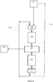
- the PGU comprises a laser diode 716, collimating surface 718, optical waveguide 717, LCOS SLM 719 and light-receiving surface 721 such as a screen or diffuser.
- the LCOS SLM 719 is arranged to display a hologram in accordance with the present disclosure.
- the hologram includes a software lens arranged to perform a Fourier transform.
- the light-receiving surface 721 is positioned at the focal length of the software lens such that a holographic reconstruction corresponding to the displayed hologram is formed thereon. The picture of the PGU is therefore formed on light-receiving surface 721.
- the components shown in Figure 7 are not to scale and the first optical sub-system has a thin physical form which allows it to be incorporated into, for example, the roof lining of the vehicle without adding significant bulk - for example, without decreasing the cabin volume.
- the optical waveguide 717 is configured to guide light from an input to an output using total internal reflection in a manner that will be familiar to the skilled reader.
- the input to the optical waveguide 717 receives collimated light from a laser diode 716.
- the collimating surface 718 may be omitted if the laser diode 716 emits collimated light or an alternative collimating element is positioned between the laser diode 716 and LCOS SLM 719. That is, collimating surface 718 is an optional feature.
- the optical waveguide 717 guides light from the laser diode 716 to the LCOS SLM 719 which spatially modulates the light in accordance with a displayed hologram.
- the picture is formed on the light-receiving surface 721 and the freeform mirror 625 is arranged to receive light of the picture from the light-receiving surface 721.
- the freeform mirror 625 reflects the light of the picture onto the windscreen as per the second group of embodiments.
- an additional optical element providing optical power - such as a lens or shaped surface - may be included between the LCOS SLM 719 and light-receiving surface 721.
- This optical element may be configured to perform the Fourier transform instead of the software lens.
- a software lens may be retained and the optical element may be configured to collectively perform the Fourier transform with the software lens. That is, the optical power required to perform the Fourier transform may be divided between the software lens and the additional optical element.
- Figure 8 represents a fourth group of arrangements in which the light-receiving surface 721 of Figure 7 is omitted.
- the holographic reconstruction is formed in free space at replay plane 822. That is, a physical component is not present at replay plane 822.
- the first optical sub-system forms a holographic reconstruction in the same way as previously described. No changes to the second optical sub-system are required to compensate for omission of the light-receiving surface.
- the skilled person will understand that, if the light-receiving surface is diffuse, omission of the light-receiving surface may reduce the size of the so-called eyebox of the HUD system but this can be addressed in other ways outside the scope of the present disclosure.
- the (holographic) replay plane may be formed after the second optical sub-system.
- the optical power of the freeform optic 625 may contribute to the Fourier transform or even provide all of the necessary optical power required for the Fourier transform.
- the replay plane may be coincident with the viewing plane - that is, the plane containing the viewer's eyes.
- Figure 9 represents a fifth group of embodiments in which the light pattern projected to the viewer is a holographic light field (that is, directly corresponding to the holographic recording) not the holographic reconstruction.
- Figure 9 therefore differs from Figure 8 in that the required Fourier transform is performed by the lens of the eye of the viewer.
- a holographic reconstruction is not therefore formed in the free space before the viewer.
- the optical components of the system including LCOS SLM 919, do not individually or collectively perform a Fourier transform.
- the hologram pattern is projected and the optical power of the lens in the viewer's eye performs the necessary Fourier transform.
- the second optical sub-system comprises freeform mirror 925 which projects an image of the hologram down the bonnet of the vehicle.
- the freeform mirror 925 may magnify the image of the hologram and may optionally correct for optical aberrations in the system or the complex shape of the windscreen.
- the second optical sub-system within the dashboard may include a plurality of optical elements such as a plurality of mirrors.
- the freeform mirror 625/925 may be replaced by a plurality of optical elements - e.g. two or three mirrors - which collectively perform the same functionality as freeform mirror 625/925.
- the optical processing - e.g. magnifying, aberration correction etc - performed by the freeform mirror 625/925 may be divided between a plurality of optical elements - e.g. mirrors.
- any other conventional optics, such as lenses and filters, may be included in the second optical sub-system to provide the HUD described.
- the light of the picture may be narrowband (in wavelength) because a laser, such as a laser diode, is used as the light source.
- At least one of the optical components in the first or second optical sub-system may therefore comprise a wavelength-selective filter, such as a laser-line filter, arranged to allow light of the picture to propagate through the optical system described but attenuate or eliminate light of other wavelengths from the optical system.
- freeform mirror 625/925 may comprises a reflective laser-line filter arranged to reflect light of the picture but absorb or transmit light of other wavelengths such as light from sun including unwanted infrared and/or ultra-violet light.
- the light of the picture may be linearly polarised because a polarisation-sensitive device, such as a LCOS device, is used as the spatial light modulator. Therefore, at least one of the optical components in the first or second optical sub-system may comprise a polariser or a polarising film, such as a polarising coating, to attenuate or eliminate stray light of the orthogonal polarisation such as sunlight of the orthogonal polarisation.
- Embodiments and arrangements refer to an electrically-activated LCOS spatial light modulator by way of example only.
- the teachings of the present disclosure may equally be implemented on any spatial light modulator capable of displaying a computer-generated hologram in accordance with the present disclosure such as any electrically-activated SLMs, optically-activated SLM, digital micromirror device or microelectromechanical device, for example.
- the light source is a laser such as a laser diode.
- the light receiving surface is a diffuser surface or screen such as a diffuser.
- a vehicle comprising the holographic projection system installed in the vehicle to provide a HUD.
- the vehicle may be an automotive vehicle such as a car, truck, van, lorry, motorcycle, train, airplane, boat, or ship.
- the quality of the holographic reconstruction may be affect by the so-called zero order problem which is a consequence of the diffractive nature of using a pixelated spatial light modulator.
- Such zero-order light can be regarded as "noise" and includes for example specularly reflected light, and other unwanted light from the SLM.
- this "noise" is focussed at the focal point of the Fourier lens leading to a bright spot at the centre of the holographic reconstruction.
- the zero order light may be simply blocked out however this would mean replacing the bright spot with a dark spot.
- Some embodiments include an angularly selective filter to remove only the collimated rays of the zero order.
- Embodiments also include the method of managing the zero-order described in European patent 2,030,072 , which is hereby incorporated in its entirety by reference.
- the size (number of pixels in each direction) of the hologram is equal to the size of the spatial light modulator so that the hologram fills the spatial light modulator. That is, the hologram uses all the pixels of the spatial light modulator. In other embodiments, the size of the hologram is less than the size of the spatial light modulator. In some of these other embodiments, part of the hologram (that is, a continuous subset of the pixels of the hologram) is repeated in the unused pixels. This technique may be referred to as "tiling" wherein the surface area of the spatial light modulator is divided up into a number of "tiles", each of which represents at least a subset of the hologram. Each tile is therefore of a smaller size than the spatial light modulator.
- the size of the holographic replay field (i.e. the physical or spatial extent of the holographic reconstruction) is determined by the pixel spacing of the spatial light modulator (i.e. the distance between adjacent light-modulating elements, or pixels, of the spatial light modulator).
- the smallest feature which may be formed in the replay field may be called a "resolution element", "image spot” or an "image pixel”.
- each pixel of the spatial light modulator has a quadrangular shape.
- the Fourier transform of a quadrangular aperture is a sine function and therefore each image pixel is a sine function. More specifically, the spatial intensity distribution of each image pixel on the replay field is a sine function.
- Each sine function may be considered as comprising a peak-intensity primary diffractive order and a series of decreasing-intensity higher diffractive orders extending radially away from the primary order.
- the size of each sine function i.e the physical or spatial extent of each sine function
- the size of the spatial light modulator i.e. the physical or spatial extent of the aperture formed by the array of light-modulating elements or spatial light modulator pixels. Specifically, the larger the aperture formed by the array of light-modulating pixels, the smaller the image pixels. It is usually desirable to have small image pixels.
- the technique of "tiling” is implemented to increase image quality. Specifically, some embodiments implement the technique of tiling to minimise the size of the image pixels whilst maximising the amount of signal content going into the holographic reconstruction.
- the holographic pattern written to the spatial light modulator comprises at least one whole tile (that is, the complete hologram) and at least one fraction of a tile (that is, a continuous subset of pixels of the hologram).
- the holographic reconstruction is created within the zeroth diffraction order of the overall window defined by the spatial light modulator. It is preferred that the first and subsequent orders are displaced far enough so as not to overlap with the image and so that they may be blocked using a spatial filter.
- the holographic reconstruction is colour.
- three different colour light sources and three corresponding SLMs are used to provide composite colour. These examples may be referred to as spatially-separated colour, "SSC".
- SSC spatially-separated colour
- the different holograms for each colour are displayed on different area of the same SLM and then combining to form the composite colour image.
- the skilled person will understand that at least some of the devices and methods of the present disclosure are equally applicable to other methods of providing composite colour holographic images.
- FSC Frame Sequential Colour
- three lasers are used (red, green and blue) and each laser is fired in succession at a single SLM to produce each frame of the video.
- the colours are cycled (red, green, blue, red, green, blue, etc.) at a fast enough rate such that a human viewer sees a polychromatic image from a combination of the images formed by three lasers.
- Each hologram is therefore colour specific. For example, in a video at 25 frames per second, the first frame would be produced by firing the red laser for 1/75th of a second, then the green laser would be fired for 1/75th of a second, and finally the blue laser would be fired for 1/75th of a second. The next frame is then produced, starting with the red laser, and so on.
- An advantage of FSC method is that the whole SLM is used for each colour. This means that the quality of the three colour images produced will not be compromised because all pixels of the SLM are used for each of the colour images.
- a disadvantage of the FSC method is that the overall image produced will not be as bright as a corresponding image produced by the SSC method by a factor of about 3, because each laser is only used for a third of the time. This drawback could potentially be addressed by overdriving the lasers, or by using more powerful lasers, but this would require more power to be used, would involve higher costs and would make the system less compact.
- An advantage of the SSC method is that the image is brighter due to all three lasers being fired at the same time.
- the surface area of the SLM can be divided into three parts, acting in effect as three separate SLMs.
- the drawback of this is that the quality of each single-colour image is decreased, due to the decrease of SLM surface area available for each monochromatic image.
- the quality of the polychromatic image is therefore decreased accordingly.
- the decrease of SLM surface area available means that fewer pixels on the SLM can be used, thus reducing the quality of the image.
- the quality of the image is reduced because its resolution is reduced.
- Embodiments utilise the improved SSC technique disclosed in British patent 2,496,108 which is hereby incorporated in its entirety by reference.
- the skilled person will be aware of techniques for converting infrared and ultraviolet light into visible light for the purpose of providing the information to a user.
- the present disclosure extends to using phosphors and/or quantum dot technology for this purpose.
- the holographic reconstruction is a 3D holographic reconstruction. That is, in some embodiments, each computer-generated hologram forms a 3D holographic reconstruction.
- the methods and processes described herein may be embodied on a computer-readable medium.
- the term "computer-readable medium” includes a medium arranged to store data temporarily or permanently such as random-access memory (RAM), read-only memory (ROM), buffer memory, flash memory, and cache memory.
- RAM random-access memory
- ROM read-only memory
- buffer memory buffer memory
- flash memory flash memory
- cache memory cache memory
- computer-readable medium shall also be taken to include any medium, or combination of multiple media, that is capable of storing instructions for execution by a machine such that the instructions, when executed by one or more processors, cause the machine to perform any one or more of the methodologies described herein, in whole or in part.
- computer-readable medium also encompasses cloud-based storage systems.
- computer-readable medium includes, but is not limited to, one or more tangible and non-transitory data repositories (e.g., data volumes) in the example form of a solid-state memory chip, an optical disc, a magnetic disc, or any suitable combination thereof.
- the instructions for execution may be communicated by a carrier medium. Examples of such a carrier medium include a transient medium (e.g., a propagating signal that communicates instructions).
Description
- The present disclosure relates to a projector and a head-up display. More specifically, the present disclosure relates to a holographic projector and a head-up display for a vehicle such as an automotive vehicle. The present disclosure also relates to a method of holographic projection and a method of projecting a virtual image in a head-up display.
- Light scattered from an object contains both amplitude and phase information. This amplitude and phase information can be captured on, for example, a photosensitive plate by well-known interference techniques to form a holographic recording, or "hologram", comprising interference fringes. The hologram may be reconstructed by illumination with suitable light to form a two-dimensional or three-dimensional holographic reconstruction, or replay image, representative of the original object.
- Computer-generated holography may numerically simulate the interference process. A computer-generated hologram, "CGH", may be calculated by a technique based on a mathematical transformation such as a Fresnel or Fourier transform. These types of holograms may be referred to as Fresnel or Fourier holograms. A Fourier hologram may be considered a Fourier domain representation of the object or a frequency domain representation of the object. A CGH may also be calculated by coherent ray tracing or a point cloud technique, for example.
- A CGH may be encoded on a spatial light modulator, "SLM", arranged to modulate the amplitude and/or phase of incident light. Light modulation may be achieved using electrically-addressable liquid crystals, optically-addressable liquid crystals or micro-mirrors, for example.
- The SLM may comprise a plurality of individually-addressable pixels which may also be referred to as cells or elements. The light modulation scheme may be binary, multilevel or continuous. Alternatively, the device may be continuous (i.e. is not comprised of pixels) and light modulation may therefore be continuous across the device. The SLM may be reflective meaning that modulated light is output from the SLM in reflection. The SLM may equally be transmissive meaning that modulated light is output from the SLM is transmission.
- A holographic projector for imaging may be provided using the described technology. Such projectors have found application in head-up displays, "HUD", and head-mounted displays, "HMD", including near-eye devices, for example.
- Cabin space is at a premium in vehicles, such as automotive vehicles, particularly as more and more advanced driver assistance systems are included. Head-up displays typically consume a relatively large volume, such as 15 litres, of the space underneath the dashboard. There is disclosed a head-up display in which less space underneath the dashboard is used to house components of the head-up display.
- Aspects of the present disclosure are defined in the appended independent claims.
- The picture generating unit may comprise a holographic projector in which the picture is a holographic reconstruction of a computer-generated hologram. The picture may be formed on a light receiving surface which acts as a display surface. A HUD based on the holographic projector described in full below is able to deliver a much greater contrast ratio than currently available competing technologies because of the efficiency of the holographic process and its inherent suitability for use with a laser light source.
- The head-up display may comprise a holographic processor. The picture may be a holographic reconstruction. The holographic processor may be arranged to output the computer-generated hologram to a spatial light modulator. The computer-generated hologram may be arranged to at least partially compensate for the shape of the windscreen of the vehicle.
- The system may be arranged to form the virtual image of the picture using the windscreen by reflecting spatially-modulated light off the windscreen. The light source may be a laser and/or the light of the picture may be laser light. The spatial light modulator may be a liquid crystal on silicon spatial light modulator. The picture may be formed by an interference process of the spatially-modulated light at the light receiving surface. The computer-generated hologram may correspond to a mathematical transformation of the corresponding picture, optionally, a Fourier or Fresnel transformation. The computer-generated hologram may be a Fourier or Fresnel hologram. The computer-generated hologram may be a hologram computer-generated by a point cloud method. The spatial light modulator may be arranged to spatially-modulate the phase of the light from the light source. The spatial light modulator may be arranged to spatially-modulate the amplitude of the light from the light source.
- However, some arrangements describe a picture generating unit based on holographic projection by way of example only. The present disclosure is equally applicable to any type of picture generating unit including a backlit liquid crystal display, a laser scanning display, a digital micro-mirror device "DMD", a fluorescent display and a plasma display.
- There is provided a head-up display for a vehicle arranged to display a picture, the head-up display comprises a first optical sub-system disposed proximate an upper region of the windscreen and a second optical sub-system disposed proximate a lower region of the windscreen such as underneath the dashboard of the vehicle. The first optical sub-system is arranged to output a light field. The first optical sub-system comprises a light source and a spatial light modulator. The light source is arranged to emit light. The spatial light modulator is arranged to receive the light from the light source and spatially-modulate the light in accordance with a computer-generated hologram displayed on the spatial light modulator. The second optical sub-system is arranged to receive the light field from the first optical sub-system and project the light field towards a windscreen of the vehicle to form a virtual image using the windscreen.
- The light field corresponds to the spatially-modulated light. That is, the light field and spatially-modulated light are related and one may be derived from the other. In this respect, it may also be said that the light field is representative of the spatially-modulated light. According to embodiments, the light field is the spatially-modulated light. That is, the wave-front of the light field and the wave-front of the spatially-modulated light may have the same amplitude and phase distribution - although they may be of different size (e.g. the spatially-modulated light may be magnified to form the light field). In comparative examples, the wave-front of the light field is a complex transform, such as a Fourier or Fresnel transform, of the wave-front of the spatially-modulated light formed by the spatial light modulator. In examples, the spatially-modulated light is representative of the light field in the frequency (or Fourier) domain. For example, the spatially-modulated light may be processed, such as Fourier or Fresnel transformed, in order to form the light field. The Fourier or Fresnel transform may be performed by a software lens integrated into the hologram, as described below. Alternatively, or additionally, the Fourier or Fresnel transform may be performed by a physical optical component such as a correctly-positioned lens.
- Conventionally, the components of a head-up display are integrated into a single unit designed to fit in an allocated volume underneath the dashboard. However, head-up display units are relatively large (compared to other electronic systems in a vehicle) because of the large optical throw required to magnify the image on a small display device (typically only a few centimetres) to form an adequately-sized image on the windscreen. The head-up display described herein comprises key components disposed in an upper region of the windscreen (that is, the region proximate the upper part of the windscreen) and key components disposed underneath the dashboard. In particular, the head-up display is broken up into two optical sub-systems which are spatially separated (or displaced). Advantageously, less volume is consumed underneath the dashboard. This is advantageous because the space underneath the dashboard, in particular, is at a premium especially as vehicles become more advanced and the demand rises for HUDs with higher fields of view.
- The optical path from the first optical sub-system to the second optical sub-system may be substantially parallel with the general plane of the windscreen. The optical path from the first optical sub-system to the second optical sub-system may also be proximate the surface of the windscreen such as within 30 cms - for example, 20 or 10 cms - of the general plane of the windscreen.
- In some arrangements, the first optical sub-system may be a picture generating unit which outputs a picture. In these cases, the light field is the picture and the virtual image is a virtual image of the picture. In this configuration, the first optical sub-system is responsible for the picture generation aspects and the second optical sub-system is responsible for the projection aspects. Accordingly, the system is conveniently modular and sub-systems may be individually tuned or changed as required - e.g. for different vehicles or to provide different specifications.
- In some arrangements, the spatially-modulated light may form the picture on a light-receiving surface of the first optical sub-system. The light-receiving surface can be used to provide additional functionality such as speckle reduction or eye-box expansion.
- In some arrangements, the spatially-modulated light may form the picture in free space between the spatial light modulator and second optical sub-system. The absence of a light-receiving surface reduces component count and can reduce optical losses.
- In embodiments, the first optical sub-system may project the spatially-modulated light encoded with the hologram data. In these cases, the output of the first optical sub-system is a light field corresponding/related to the picture but is not the picture itself. The light field may be a Fourier transform of the picture. In these cases, the light field is the spatially-modulated light.
- The eye lens of the viewer may perform an optical Fourier transform of the spatially-modulated light. Advantageously, because the focal length of the human eye is adaptable, holographic images may be made to appear at different distances from the viewer. That is, the position of the replay plane may be dynamically changed. Accordingly, a multi-plane such as dual plane head-up display is provided. In some alternative arrangements, the second optical sub-system may be arranged to perform an optical Fourier transform of the spatially-modulated light.
- The first optical sub-system may be disposed: on the vehicle roof; within the internal roof liner; on the rear-view mirror housing; on a roofline electronics panel; or on the sun visors. Accordingly, key components are disposed in areas of the vehicle having lower real-estate value than underneath the dashboard.
- The second optical sub-system may comprise at least one reflective element such as a mirror. This enables a space-efficient optical system to be formed - e.g. using a folded optical path - and provides an optical surface which can be used for optically processing the image. The at least one reflective element of the second optical sub-system may have optical power. This feature delivers the necessary image magnification. The at least one reflective element of the second optical sub-system may be a freeform optic or may comprise a freeform optical surface arranged to at least partially compensate for the shape of the windscreen in the area of the windscreen which receives light of the picture. This provides improved image quality. The at least one reflective element may comprise a laser-line selective filter arranged to allow propagation of light of the picture through the head-up display and supress the propagation of light of having a different wavelength through the head-up display. This significantly reduces the amount of sunlight passing back through the system and mitigates the problems associated therewith - such as optical wash-out of the image or thermal damage optical components such as the spatial light modulator. Alternatively, or additionally, the at least one reflective element of the second optical sub-system may further comprise a polariser, such as a polarising film or coating thereon, arranged to allow propagation of light of the picture through the head-up display and supress, such as attenuate or block, the propagation of light having the orthogonal polarisation through the head-up display. Again, this leads to a reduction in sunlight passing back through the system.
- The first optical sub-system may be substantially planar and comprise a substantially planar waveguide arranged to guide light from the light source to the spatial light modulator and guide spatially-modulated light from the spatial light modulator to an output of the waveguide along a continuous optical path. There is therefore provided a substantially planar configuration which is adaptable and has a suitable form-factor for attaching to the roof or fitting within the internal roof-liner structure thereby minimising any impact on the cabin space. The continuous optical path within the waveguide may traverse the longitudinal axis of the waveguide plural time by total internal reflection at the surface of the waveguide.
- The first optical sub-system may comprise at least one reflective element such as a mirror. Accordingly, an adjustable (e.g. twist/tilt) component is provided which may be used to maintain optical alignment. Furthermore, additional design flexibility is provided. The at least one reflective element of the first optical sub-system may have optical power. Accordingly, the demand placed on the second optical sub-system - such as the demand to provide optical power - may be relaxed. The at least one reflective element of the first optical sub-system may be a freeform optic or may comprise a freeform optical surface arranged to at least partially compensate for the shape of the windscreen in the area of the windscreen which receives light of the picture. The at least one reflective element may comprise a laser-line selective filter arranged to allow propagation of light of the picture through the head-up display and supress the propagation of light of having a different wavelength through the head-up display. Alternatively, or additionally, the at least one reflective element of the first optical sub-system may further comprise a polariser, such as a polarising film or coating thereon, arranged to allow propagation of light of the picture through the head-up display and supress, such as attenuate or block, the propagation of light having the orthogonal polarisation through the head-up display.
- There is provided a head-up display system in a vehicle, the system comprising: a first optical sub-system comprising a picture generating unit arranged to output a light field; and a second optical sub-system arranged to receive the light field from the first optical sub-system and project the light field onto a windscreen of the vehicle to form a virtual image on the windscreen, wherein the first optical sub-system is disposed in an upper region of the windscreen and the second optical sub-system is disposed within the dashboard of the vehicle proximate a lower region of the windscreen.
- There is provided a head-up display in a vehicle arranged to display a picture, the head-up display comprising: a first optical sub-system arranged to output a holographic light field, wherein the first optical sub-system comprises: a light source arranged to emit light; a spatial light modulator arranged to receive the light from the light source and spatially-modulate the light in accordance with a computer-generated hologram represented on the spatial light modulator to form the holographic light field, wherein the holographic light field is a frequency domain representation of the picture; and a holographic processor arranged to output the computer-generated hologram to the spatial light modulator; and a second optical sub-system arranged to receive the holographic light field from the first optical sub-system and project the holographic light field onto a windscreen of the vehicle to form a virtual image on the windscreen, wherein the first optical sub-system is disposed in an upper region of the windscreen and the second optical sub-system is disposed within the dashboard of the vehicle proximate a lower region of the windscreen. A holographic light field is a light field having a wave-front spatially-modulated in accordance with the hologram displayed on the spatial light modulator.
- According to alternative arrangements, there is provided a head-up display in a vehicle arranged to display a picture, the head-up display comprising: a first optical sub-system arranged to output the picture, wherein the first optical sub-system comprises: a light source arranged to emit light; a spatial light modulator arranged to receive the light from the light source and output spatially-modulated light forming the picture in accordance with a computer-generated hologram represented on the spatial light modulator; and a holographic processor arranged to output the computer-generated hologram to the spatial light modulator; and a second optical sub-system arranged to receive light of the picture from the first optical sub-system and project the light of the picture onto a windscreen of the vehicle to form a virtual image of the picture on the windscreen, wherein the first optical sub-system is disposed in an upper region of the windscreen and the second optical sub-system is disposed within the dashboard of the vehicle proximate a lower region of the windscreen.
- The term "light of the picture" is used herein to refer to the light which forms the picture. The "light of the picture" may be monochromatic or polychromatic. The "light of the picture" may be composite colour. For example, the "light of the picture" may comprise red, green and blue light. The "light of the picture" may be polarised.
- The reader will be familiar with the position of the dashboard in a vehicle during normal use. The second optical sub-system in accordance with this disclosure is described as being disposed "underneath" the dashboard of the vehicle. This terminology is used to reflect that the second optical sub-system is below the surface of the dashboard. More specifically, the entire volume of the second optical sub-system, including the upper most part thereof, is positioned below the surface of the dashboard of the vehicle when in normal use. For example, the second optical sub-system may be disposed within the dashboard or inside the dashboard. The outer most top surface behind the instrument cluster and in front of the windscreen is sometimes referred to as the A-surface or "topper". It may therefore be said that the second optical subs-system is underneath the A-surface of topper.
- In accordance with this disclosure a "laser-line selective filter" allows laser-line light to propagate on the optical path described but does not allow non laser-line light to propagate any further on the optical path. In other words, the "laser-line selective filter" removes non laser-line light from the optical system. For example, the "laser-line selective filter" may absorb non laser-line light. For example, a "laser-line selective filter" may be absorb all optical wavelengths except light having the laser-line wavelength. Alternatively, the filter may achieve this selective functionality by being preferentially transmissive or preferentially reflective, for example, to the laser-line light. Likewise, a "polarisation-selective filter" in accordance with this disclosure refers to a filter which removes light having the non-preferential polarisation from the optical system. The term "laser-line" is used to refer to a narrow bandwidth having a centre wavelength and a full-wave half-maximum of less than 30 nm, optionally less than 15 nm, further optionally less than 5 nm.
- The term "hologram" is used to refer to the recording which contains amplitude information or phase information, or some combination thereof, about the object. The term "holographic reconstruction" is used to refer to the optical reconstruction of the object which is formed by illuminating the hologram. The term "replay plane" is used herein to refer to the plane in space where the holographic reconstruction is fully formed. The term "replay field" is used herein to refer to the sub-area of the replay plane which can receive spatially-modulated light from the spatial light modulator. The terms "image", "replay image" and "image region" refer to areas of the replay field illuminated by light forming the holographic reconstruction. In embodiments, the "image" may comprise discrete spots which may be referred to as "image pixels".
- The terms "encoding", "writing" or "addressing" are used to describe the process of providing the plurality of pixels of the SLM with a respect plurality of control values which respectively determine the modulation level of each pixel. It may be said that the pixels of the SLM are configured to "display" a light modulation distribution in response to receiving the plurality of control values. Thus, the SLM may be said to "display" a hologram.
- It has been found that a holographic reconstruction of acceptable quality can be formed from a "hologram" containing only phase information related to the original object. Such a holographic recording may be referred to as a phase-only hologram. Examples relate to a phase-only hologram but the present disclosure is equally applicable to amplitude-only holography.
- The present disclosure is also equally applicable to forming a holographic reconstruction using amplitude and phase information related to the original object. In some embodiments, this is achieved by complex modulation using a so-called fully complex hologram which contains both amplitude and phase information related to the original object. Such a hologram may be referred to as a fully-complex hologram because the value (grey level) assigned to each pixel of the hologram has an amplitude and phase component. The value (grey level) assigned to each pixel may be represented as a complex number having both amplitude and phase components. In some embodiments, a fully-complex computer-generated hologram is calculated.
- Reference may be made to the phase value, phase component, phase information or, simply, phase of pixels of the computer-generated hologram or the spatial light modulator as shorthand for "phase-delay". That is, any phase value described is, in fact, a number (e.g. in the range 0 to 2π) which represents the amount of phase retardation provided by that pixel. For example, a pixel of the spatial light modulator described as having a phase value of π/2 will change the phase of received light by π/2 radians. In some embodiments, each pixel of the spatial light modulator is operable in one of a plurality of possible modulation values (e.g. phase delay values). The term "grey level" may be used to refer to the plurality of available modulation levels. For example, the term "grey level" may be used for convenience to refer to the plurality of available phase levels in a phase-only modulator even though different phase levels do not provide different shades of grey. The term "grey level" may also be used for convenience to refer to the plurality of available complex modulation levels in a complex modulator.
- Although different embodiments, arrangements and groups of embodiments and groups of arrangements may be disclosed separately in the detailed description which follows, any feature of any embodiment, arrangement or group of embodiments or group of arrangements may be combined with any other feature or combination of features of any embodiment, arrangement or group of embodiments or group of arrangements. That is, all possible combinations and permutations of features disclosed in the present disclosure are envisaged.
- Specific embodiments and arrangements are described by way of example only with reference to the following figures:
-
Figure 1 is a schematic showing a reflective SLM producing a holographic reconstruction on a screen; -
Figure 2A illustrates a first iteration of an example Gerchberg-Saxton type algorithm; -
Figure 2B illustrates the second and subsequent iterations of the example Gerchberg-Saxton type algorithm; -
Figure 2C illustrates alternative second and subsequent iterations of the example Gerchberg-Saxton type algorithm; -
Figure 3 is a schematic of a reflective LCOS SLM; -
Figure 4 shows an example HUD in a vehicle; -
Figure 5 is representative of a first group of arrangements; -
Figure 6 is representative of a second group of arrangements; -
Figure 7 is representative of a third group of arrangements; -
Figure 8 is representative of a fourth group of arrangements; and -
Figure 9 is representative of a fifth group of embodiments. - The same reference numbers will be used throughout the drawings to refer to the same or like parts.
- The present invention is not restricted to the embodiments and arrangements described in the following but extends to the full scope of the appended claims. That is, the present invention may be embodied in different forms and should not be construed as limited to the described embodiments and arrangements, which are set out for the purpose of illustration.
- Terms of a singular form may include plural forms unless specified otherwise.
- A structure described as being formed at an upper portion/lower portion of another structure or on/under the other structure should be construed as including a case where the structures contact each other and, moreover, a case where a third structure is disposed there between.
- In describing a time relationship - for example, when the temporal order of events is described as "after", "subsequent", "next", "before" or suchlike - the present disclosure should be taken to include continuous and non-continuous events unless otherwise specified. For example, the description should be taken to include a case which is not continuous unless wording such as "just", "immediate" or "direct" is used.
- Although the terms "first", "second", etc. may be used herein to describe various elements, these elements are not be limited by these terms. These terms are only used to distinguish one element from another. For example, a first element could be termed a second element, and, similarly, a second element could be termed a first element, without departing from the scope of the appended claims.
- Features of different embodiments and arrangements may be partially or overall coupled to or combined with each other, and may be variously inter-operated with each other. Some embodiments or arrangements may be carried out independently from each other, or may be carried out together in co-dependent relationship.
-
Figure 1 shows an arrangement in which a computer-generated hologram is encoded on a single spatial light modulator. The computer-generated hologram is a Fourier transform of the object for reconstruction. It may therefore be said that the hologram is a Fourier domain or frequency domain or spectral domain representation of the object. In this arrangement, the spatial light modulator is a reflective liquid crystal on silicon, "LCOS", device. The hologram is encoded on the spatial light modulator and a holographic reconstruction is formed at a replay field, for example, a light receiving surface such as a screen or diffuser. - A
light source 110, for example a laser or laser diode, is disposed to illuminate theSLM 140 via acollimating lens 111. The collimating lens causes a generally planar wave-front of light to be incident on the SLM. InFigure 1 , the direction of the wave-front is off-normal (e.g. two or three degrees away from being truly orthogonal to the plane of the transparent layer). However, in other arrangements, the generally planar wave-front is provided at normal incidence and a beam splitter arrangement is used to separate the input and output optical paths. InFigure 1 , the arrangement is such that light from the light source is reflected off a mirrored rear surface of the SLM and interacts with a light-modulating layer to form an exit wave-front 112. The exit wave-front 112 is applied to optics including aFourier transform lens 120, having its focus at ascreen 125. More specifically, theFourier transform lens 120 receives a beam of modulated light from theSLM 140 and performs a frequency-space transformation to produce a holographic reconstruction at thescreen 125. - Notably, in this type of holography, each pixel of the hologram contributes to the whole reconstruction. There is not a one-to-one correlation between specific points (or image pixels) on the replay field and specific light-modulating elements (or hologram pixels). In other words, modulated light exiting the light-modulating layer is distributed across the replay field.
- In these arrangements, the position of the holographic reconstruction in space is determined by the dioptric (focusing) power of the Fourier transform lens. In
Figure 1 , the Fourier transform lens is a physical lens. That is, the Fourier transform lens is an optical Fourier transform lens and the Fourier transform is performed optically. Any lens can act as a Fourier transform lens but the performance of the lens will limit the accuracy of the Fourier transform it performs. The skilled person understands how to use a lens to perform an optical Fourier transform. - In some embodiments, the computer-generated hologram is a Fourier transform hologram, or simply a Fourier hologram or Fourier-based hologram, in which an image is reconstructed in the far field by utilising the Fourier transforming properties of a positive lens. The Fourier hologram is calculated by Fourier transforming the desired light field in the replay plane back to the lens plane. Computer-generated Fourier holograms may be calculated using Fourier transforms.
- A Fourier transform hologram may be calculated using an algorithm such as the Gerchberg-Saxton algorithm. Furthermore, the Gerchberg-Saxton algorithm may be used to calculate a hologram in the Fourier domain (i.e. a Fourier transform hologram) from amplitude-only information in the spatial domain (such as a photograph). The phase information related to the object is effectively "retrieved" from the amplitude-only information in the spatial domain. In some embodiments, a computer-generated hologram is calculated from amplitude-only information using the Gerchberg-Saxton algorithm or a variation thereof.
- The Gerchberg Saxton algorithm considers the situation when intensity cross-sections of a light beam, IA(x, y) and IB(x, y), in the planes A and B respectively, are known and IA(x, y) and IB(x, y) are related by a single Fourier transform. With the given intensity cross-sections, an approximation to the phase distribution in the planes A and B, ψA(x, y) and ψB(x, y) respectively, is found. The Gerchberg-Saxton algorithm finds solutions to this problem by following an iterative process. More specifically, the Gerchberg-Saxton algorithm iteratively applies spatial and spectral constraints while repeatedly transferring a data set (amplitude and phase), representative of IA(x, y) and IB(x, y), between the spatial domain and the Fourier (spectral or frequency) domain. The corresponding computer-generated hologram in the spectral domain is obtained through at least one iteration of the algorithm. The algorithm is convergent and arranged to produce a hologram representing an input image. The hologram may be an amplitude-only hologram, a phase-only hologram or a fully complex hologram.
- In some embodiments, a phase-only hologram is calculated using an algorithm based on the Gerchberg-Saxton algorithm such as described in
British patent 2,498,170 2,501,112 - In other embodiments, an algorithm based on the Gerchberg-Saxton algorithm is used to calculate a fully-complex hologram. A fully-complex hologram is a hologram having a magnitude component and a phase component. The hologram is a data set (e.g. 2D array) comprising an array of complex data values wherein each complex data value comprises a magnitude component and a phase component.
- In some embodiments, the algorithm processes complex data and the Fourier transforms are complex Fourier transforms. Complex data may be considered as comprising (i) a real component and an imaginary component or (ii) a magnitude component and a phase component. In some embodiments, the two components of the complex data are processed differently at various stages of the algorithm.
-
Figure 2A illustrates the first iteration of an algorithm in accordance with some embodiments for calculating a phase-only hologram. The input to the algorithm is aninput image 210 comprising a 2D array of pixels or data values, wherein each pixel or data value is a magnitude, or amplitude, value. That is, each pixel or data value of theinput image 210 does not have a phase component. Theinput image 210 may therefore be considered a magnitude-only or amplitude-only or intensity-only distribution. An example of such aninput image 210 is a photograph or one frame of video comprising a temporal sequence of frames. The first iteration of the algorithm starts with adata forming step 202A comprising assigning a random phase value to each pixel of the input image, using a random phase distribution (or random phase seed) 230, to form a starting complex data set wherein each data element of the set comprising magnitude and phase. It may be said that the starting complex data set is representative of the input image in the spatial domain. -
First processing block 250 receives the starting complex data set and performs a complex Fourier transform to form a Fourier transformed complex data set.Second processing block 253 receives the Fourier transformed complex data set and outputs ahologram 280A. In some embodiments, thehologram 280A is a phase-only hologram. In these embodiments,second processing block 253 quantises each phase value and sets each amplitude value to unity in order to formhologram 280A. Each phase value is quantised in accordance with the phase-levels which may be represented on the pixels of the spatial light modulator which will be used to "display" the phase-only hologram. For example, if each pixel of the spatial light modulator provides 256 different phase levels, each phase value of the hologram is quantised into one phase level of the 256 possible phase levels.Hologram 280A is a phase-only Fourier hologram which is representative of an input image. In other embodiments, thehologram 280A is a fully complex hologram comprising an array of complex data values (each including an amplitude component and a phase component) derived from the received Fourier transformed complex data set. In some embodiments,second processing block 253 constrains each complex data value to one of a plurality of allowable complex modulation levels to formhologram 280A. The step of constraining may include setting each complex data value to the nearest allowable complex modulation level in the complex plane. It may be said thathologram 280A is representative of the input image in the spectral or Fourier or frequency domain. In some embodiments, the algorithm stops at this point. - However, in other embodiments, the algorithm continues as represented by the dotted arrow in
Figure 2A . In other words, the steps which follow the dotted arrow inFigure 2A are optional (i.e. not essential to all embodiments). -
Third processing block 256 receives the modified complex data set from thesecond processing block 253 and performs an inverse Fourier transform to form an inverse Fourier transformed complex data set. It may be said that the inverse Fourier transformed complex data set is representative of the input image in the spatial domain. -
Fourth processing block 259 receives the inverse Fourier transformed complex data set and extracts the distribution of magnitude values 211A and the distribution ofphase values 213A. Optionally, thefourth processing block 259 assesses the distribution of magnitude values 211A. Specifically, thefourth processing block 259 may compare the distribution of magnitude values 211A of the inverse Fourier transformed complex data set with theinput image 510 which is itself, of course, a distribution of magnitude values. If the difference between the distribution of magnitude values 211A and theinput image 210 is sufficiently small, thefourth processing block 259 may determine that thehologram 280A is acceptable. That is, if the difference between the distribution of magnitude values 211A and theinput image 210 is sufficiently small, thefourth processing block 259 may determine that thehologram 280A is a sufficiently-accurate representative of theinput image 210. In some embodiments, the distribution ofphase values 213A of the inverse Fourier transformed complex data set is ignored for the purpose of the comparison. It will be appreciated that any number of different methods for comparing the distribution of magnitude values 211A and theinput image 210 may be employed and the present disclosure is not limited to any particular method. In some embodiments, a mean square difference is calculated and if the mean square difference is less than a threshold value, thehologram 280A is deemed acceptable. If thefourth processing block 259 determines that thehologram 280A is not acceptable, a further iteration of the algorithm may performed. However, this comparison step is not essential and in other embodiments, the number of iterations of the algorithm performed is predetermined or preset or user-defined. -
Figure 2B represents a second iteration of the algorithm and any further iterations of the algorithm. The distribution ofphase values 213A of the preceding iteration is fed-back through the processing blocks of the algorithm. The distribution ofmagnitude values 211A is rejected in favour of the distribution of magnitude values of theinput image 210. In the first iteration, thedata forming step 202A formed the first complex data set by combining distribution of magnitude values of theinput image 210 with arandom phase distribution 230. However, in the second and subsequent iterations, thedata forming step 202B comprises forming a complex data set by combining (i) the distribution ofphase values 213A from the previous iteration of the algorithm with (ii) the distribution of magnitude values of theinput image 210. - The complex data set formed by the
data forming step 202B ofFigure 2B is then processed in the same way described with reference toFigure 2A to formsecond iteration hologram 280B. The explanation of the process is not therefore repeated here. The algorithm may stop when thesecond iteration hologram 280B has been calculated. However, any number of further iterations of the algorithm may be performed. It will be understood that thethird processing block 256 is only required if thefourth processing block 259 is required or a further iteration is required. Theoutput hologram 280B generally gets better with each iteration. However, in practice, a point is usually reached at which no measurable improvement is observed or the positive benefit of performing a further iteration is out-weighted by the negative effect of additional processing time. Hence, the algorithm is described as iterative and convergent. -
Figure 2C represents an alternative embodiment of the second and subsequent iterations. The distribution ofphase values 213A of the preceding iteration is fed-back through the processing blocks of the algorithm. The distribution ofmagnitude values 211A is rejected in favour of an alternative distribution of magnitude values. In this alternative embodiment, the alternative distribution of magnitude values is derived from the distribution of magnitude values 211 of the previous iteration. Specifically,processing block 258 subtracts the distribution of magnitude values of theinput image 210 from the distribution of magnitude values 211 of the previous iteration, scales that difference by a gain factor α and subtracts the scaled difference from theinput image 210. This is expressed mathematically by the following equations, wherein the subscript text and numbers indicate the iteration number:


- F' is the inverse Fourier transform;
- F is the forward Fourier transform;
- R[x, y] is the complex data set output by the
third processing block 256; - T[x, y] is the input or target image;
- ∠ is the phase component;
- ψ is the phase-only
hologram 280B; - η is the new distribution of magnitude values 211B; and
- α is the gain factor.
- The gain factor α may be fixed or variable. In some embodiments, the gain factor α is determined based on the size and rate of the incoming target image data. In some embodiments, the gain factor α is dependent on the iteration number. In some embodiments, the gain factor α is solely function of the iteration number.
- The embodiment of
Figure 2C is the same as that ofFigure 2A andFigure 2B in all other respects. It may be said that the phase-only hologram ψ(u, v) comprises a phase distribution in the frequency or Fourier domain. - In some arrangements, the Fourier transform is performed computationally by including lensing data in the holographic data. That is, the hologram includes data representative of a lens as well as data representing the object. In these arrangements, the physical
Fourier transform lens 120 ofFigure 1 is omitted. It is known in the field of computer-generated hologram how to calculate holographic data representative of a lens. The holographic data representative of a lens may be referred to as a software lens. For example, a phase-only holographic lens may be formed by calculating the phase delay caused by each point of the lens owing to its refractive index and spatially-variant optical path length. For example, the optical path length at the centre of a convex lens is greater than the optical path length at the edges of the lens. An amplitude-only holographic lens may be formed by a Fresnel zone plate. It is also known in the art of computer-generated hologram how to combine holographic data representative of a lens with holographic data representative of the object so that a Fourier transform can be performed without the need for a physical Fourier lens. In some arrangements, lensing data is combined with the holographic data by simple addition such as simple vector addition. In some arrangements, a physical lens is used in conjunction with a software lens to perform the Fourier transform. Alternatively, in other arrangements, the Fourier transform lens is omitted altogether such that the holographic reconstruction takes place in the far-field. In further embodiments, the hologram may include grating data - that is, data arranged to perform the function of a grating such as beam steering. Again, it is known in the field of computer-generated holography how to calculate such holographic data and combine it with holographic data representative of the object. For example, a phase-only holographic grating may be formed by modelling the phase delay caused by each point on the surface of a blazed grating. An amplitude-only holographic grating may be simply superimposed on an amplitude-only hologram representative of an object to provide angular steering of an amplitude-only hologram. - In some arrangements, the Fourier transform is performed jointly by a physical Fourier transform lens and a software lens. That is, some optical power which contributes to the Fourier transform is provided by a software lens and the rest of the optical power which contributes to the Fourier transform is provided by a physical optic or optics.
- In some embodiments, there is provided a real-time engine arranged to receive image data and calculate holograms in real-time using the algorithm. In some embodiments, the image data is a video comprising a sequence of image frames. In other embodiments, the holograms are pre-calculated, stored in computer memory and recalled as needed for display on a SLM. That is, in some embodiments, there is provided a repository of predetermined holograms.
- Embodiments relate to Fourier holography and Gerchberg-Saxton type algorithms by way of example only. The present disclosure is equally applicable to Fresnel holography and holograms calculated by other techniques such as those based on point cloud methods.
- A spatial light modulator may be used to display the computer-generated hologram. If the hologram is a phase-only hologram, a spatial light modulator which modulates phase is required. If the hologram is a fully-complex hologram, a spatial light modulator which modulates phase and amplitude may be used or a first spatial light modulator which modulates phase and a second spatial light modulator which modulates amplitude may be used.
- In some embodiments, the light-modulating elements (i.e. the pixels) of the spatial light modulator are cells containing liquid crystal. That is, in some embodiments, the spatial light modulator is a liquid crystal device in which the optically-active component is the liquid crystal. Each liquid crystal cell is configured to selectively-provide a plurality of light modulation levels. That is, each liquid crystal cell is configured at any one time to operate at one light modulation level selected from a plurality of possible light modulation levels. Each liquid crystal cell is dynamically-reconfigurable to a different light modulation level from the plurality of light modulation levels. In some embodiments, the spatial light modulator is a reflective liquid crystal on silicon (LCOS) spatial light modulator but the present disclosure is not restricted to this type of spatial light modulator.
- A LCOS device provides a dense array of light modulating elements, or pixels, within a small aperture (e.g. a few centimeters in width). The pixels are typically approximately 10 microns or less which results in a diffraction angle of a few degrees meaning that the optical system can be compact. It is easier to adequately illuminate the small aperture of a LCOS SLM than it is the larger aperture of other liquid crystal devices. An LCOS device is typically reflective which means that the circuitry which drives the pixels of a LCOS SLM can be buried under the reflective surface. The results in a higher aperture ratio. In other words, the pixels are closely packed meaning there is very little dead space between the pixels. This is advantageous because it reduces the optical noise in the replay field. A LCOS SLM uses a silicon backplane which has the advantage that the pixels are optically flat. This is particularly important for a phase modulating device.
- A suitable LCOS SLM is described below, by way of example only, with reference to
Figure 3 . An LCOS device is formed using a singlecrystal silicon substrate 302. It has a 2D array of squareplanar aluminium electrodes 301, spaced apart by agap 301a, arranged on the upper surface of the substrate. Each of theelectrodes 301 can be addressed viacircuitry 302a buried in thesubstrate 302. Each of the electrodes forms a respective planar mirror. Analignment layer 303 is disposed on the array of electrodes, and aliquid crystal layer 304 is disposed on thealignment layer 303. Asecond alignment layer 305 is disposed on the planartransparent layer 306, e.g. of glass. A singletransparent electrode 307 e.g. of ITO is disposed between thetransparent layer 306 and thesecond alignment layer 305. - Each of the
square electrodes 301 defines, together with the overlying region of thetransparent electrode 307 and the intervening liquid crystal material, a controllable phase-modulatingelement 308, often referred to as a pixel. The effective pixel area, or fill factor, is the percentage of the total pixel which is optically active, taking into account the space betweenpixels 301a. By control of the voltage applied to eachelectrode 301 with respect to thetransparent electrode 307, the properties of the liquid crystal material of the respective phase modulating element may be varied, thereby to provide a variable delay to light incident thereon. The effect is to provide phase-only modulation to the wave-front, i.e. no amplitude effect occurs. - The described LCOS SLM outputs spatially modulated light in reflection. Reflective LCOS SLMs have the advantage that the signal lines, gate lines and transistors are below the mirrored surface, which results in high fill factors (typically greater than 90%) and high resolutions. Another advantage of using a reflective LCOS spatial light modulator is that the liquid crystal layer can be half the thickness than would be necessary if a transmissive device were used. This greatly improves the switching speed of the liquid crystal (a key advantage for the projection of moving video images). However, the teachings of the present disclosure may equally be implemented using a transmissive LCOS SLM.
-
Figure 4 shows a HUD in a vehicle such as a car. Thewindscreen 430 and bonnet (or hood) 435 of the vehicle are shown inFigure 4 . The HUD comprises a picture generating unit, "PGU", 410 and anoptical system 420. - In this example, the
PGU 410 comprises a light source, a light receiving surface and a processor (or computer) arranged to computer-control the image content of the picture. ThePGU 410 is arranged to generate a picture, or sequence of pictures, on a light receiving surface. The light receiving surface may be a screen or diffuser. In some arrangements, the light receiving surface is plastic (that is, made of plastic). - The
optical system 420 comprises an input port, an output port, afirst mirror 421 and asecond mirror 422. Thefirst mirror 421 andsecond mirror 422 are arranged to guide light from the input port of the optical system to the output port of the optical system. More specifically, thesecond mirror 422 is arranged to receive light of the picture from thePGU 410 and thefirst mirror 421 is arranged to receive light of the picture from thesecond mirror 422. Thefirst mirror 421 is further arranged to reflect the received light of the picture to the output port. The optical path from the input port to the output port therefore comprises a first optical path 423 (or first optical path component) from the input to thesecond mirror 422 and a second optical path 424 (or second optical path component) from thesecond mirror 422 to thefirst mirror 421. There is, of course, a third optical path (or optical path component) from the first mirror to the output port but that is not assigned a reference numeral inFigure 4 . The optical configuration shown inFigure 4 may be referred to as a "z-fold" configuration owing to the shape of the optical path. - The HUD is configured and positioned within the vehicle such that light of the picture from the output port of the
optical system 420 is incident upon thewindscreen 430 and at least partially reflected by thewindscreen 430 to theuser 440 of the HUD. Accordingly, in embodiments, the optical system is arranged to form the virtual image of each picture in the windscreen by reflecting spatially-modulated light off the windscreen. Theuser 440 of the HUD (for example, the driver of the car) sees avirtual image 450 of the picture in thewindscreen 430. Accordingly, in embodiments, the optical system is arranged to form a virtual image of each picture on a windscreen of the vehicle. Thevirtual image 450 is formed a distance down thebonnet 435 of the car. For example, the virtual image may be 1 to 2.5 metres from theuser 440. The output port of theoptical system 420 is aligned with an aperture in the dashboard of the car such that light of the picture is directed by theoptical system 420 andwindscreen 430 to theuser 440. In this configuration, thewindscreen 430 functions as an optical combiner. In some embodiments, the optical system is arranged to form a virtual image of each picture on an additional optical combiner which is included in the system. Thewindscreen 430, or additional optical combiner if included, combines light from the real-world scene with light of the picture. It may therefore be understood that the HUD may provide augmented reality including a virtual image of the picture. For example, the augmented reality information may include navigation information or information related to the speed of the automotive vehicle. In some embodiments, the light forming the picture is output by incident upon the windscreen at Brewster's angle (also known as the polarising angle) or within 5 degrees of Brewster's angle such as within 2 degrees of Brewster's angle. - In some embodiments, the first mirror and second mirror are arranged to fold the optical path from the input to the output in order to increase the optical path length without overly increasing the physical size of the HUD.
- The picture formed on the light receiving surface of the
PGU 410 may only be a few centimetres in width and height. Thefirst mirror 421 andsecond mirror 422 therefore, collectively or individually, provide magnification. That is, the first mirror and/or second mirror may have optical power (that is, dioptric or focusing power). Theuser 440 therefore sees a magnifiedvirtual image 450 of the picture formed by the PGU. Thefirst mirror 421 andsecond mirror 422 may also correct for optical distortions such as those caused by thewindscreen 430 which typically has a complex curved shape. The folded optical path and optical power in the mirrors together allow for suitable magnification of the virtual image of the picture. - In arrangements, the
PGU 410 comprises a holographic projector and a light receiving surface such as a screen or diffuser. In accordance with the disclosure above, the holographic projector comprises a light source, a spatial light modulator and a hologram processor. The spatial light modulator is arranged to spatially-modulate light in accordance with holograms represented on the spatial light modulator. The hologram processor is arranged to provide the computer-generated holograms. In some embodiments, the hologram processor selects a computer-generated hologram for output from a repository (e.g. memory) comprising a plurality of computer-generated holograms. In other embodiments, the hologram processor calculates and outputs the computer-generated holograms in real-time. In some arrangements, each picture formed by thePGU 410 is a holographic reconstruction on the light receiving surface. That is, in some arrangements, each picture is formed by interference of the spatially-modulated light at the light receiving surface. - Embodiments and arrangements are described below with reference to
Figures 5 to 9 . These figures show only the interior/internal walls of the windscreen, bonnet and roof of the vehicle. For the avoidance of any doubt, the first optical sub-system and second optical sub-system are disposed inside the vehicle - that is, within the external walls of the vehicle. -
Figure 5 represents a first group of arrangements. There is shown anoptical path 560 from the first optical sub-system to the viewer. Specifically,Figure 5 shows a vehicle having awindscreen 530,bonnet 550 androof 540.Figure 5 also shows a firstoptical sub-system 510 directly or indirectly fixed or mounted to the roof of the vehicle, such as within the roof liner of the vehicle cabin, and secondoptical sub-system 520 mounted underneath the dashboard. The firstoptical sub-system 510 and secondoptical sub-system 520 cooperate to form a HUD for a viewer such as the driver of the vehicle. - In operation, the first
optical sub-system 510 is arranged to display a picture and the secondoptical sub-system 520 is arranged to receive light of the picture from the firstoptical sub-system 510 and project the received light of the picture onto thewindscreen 530. For example, the step of projecting the received light of the picture onto the windscreen may comprise redirecting the light of the picture or reflecting the light of the picture. The step of projecting the received light of the picture may also comprise magnifying the picture and/or manipulating the received light field to improve the quality of the virtual image such as by correcting for aberrations or the complex shape of the windscreen. The optical arrangement is such that light of the picture is reflected to the viewer. The light of the picture is incident on the windscreen at substantially Brewster's angle. A virtual image of the picture appears to the viewer a distance down the bonnet of the vehicle as shown by the dotted line inFigure 5 . -
Figure 6 represents a second group of arrangements. Specifically,Figure 6 shows aPGU 615 directly or indirectly fixed or mounted to the roof of the vehicle, such as within the roof liner of the vehicle cabin, and afreeform mirror 625 mounted underneath the dashboard. In this arrangement, the first optical sub-system comprisesPGU 615 and the second optical sub-system comprisesfreeform mirror 625. Again, for the avoidance of any doubt, thePGU 615 is not outside the vehicle. ThePGU 615 andfreeform mirror 625 collectively form a HUD for a viewer such as the driver of the vehicle. It will be understood that, for example, an aperture may be required in each of the roof liner and dashboard to provide a clear/unobstructed optical path from the first optical sub-system to the viewer via the second optical sub-system. In the arrangement shown, thePGU 615 is a holographic projector arranged to form a picture on a light-receiving surface and the picture is a holographic reconstruction of a hologram displayed on a spatial light modulator. However, the PGU may be any type of PGU as previously explained. - In operation, the
PGU 615 is arranged to generate a picture and thefreeform mirror 625 is arranged to receive light of the picture from thePGU 615 and project the received light of the picture onto thewindscreen 530. The step of projecting the received light of the picture comprises reflecting the light of the picture and magnifying the picture. In some arrangements, the step of projecting the received light of the picture further comprises correcting for aberrations and/or the complex shape of the windscreen both of which distort the virtual image. - The
freeform mirror 625 is arranged to receive light of the picture from thePGU 615 as an input and output in reflection the received light of the picture to thewindscreen 530. Thewindscreen 530 is arranged to receive the reflected light of the picture from thefreeform mirror 625 and reflect light of the picture to the viewer such that the viewer sees a virtual image of the picture in front of them such as a distance down the bonnet. - Optionally, the first optical sub-system may further comprise a mirror on the optical path between the PGU and freeform mirror. The mirror may be arranged to receive light of the picture from the PGU and reflect the received light of the picture to the freeform mirror. The PGU and additional mirror collectively form a first optical sub-system proximate the upper region of the windscreen such as within the roof liner of the vehicle cabin. The freeform mirror receives light of the picture from the mirror of the first optical sub-system and reflects the received light of the picture to the
windscreen 530 as previously described. -
Figure 7 represents a third group of arrangements. The first optical sub-system comprises a PGU. The PGU comprises alaser diode 716, collimatingsurface 718,optical waveguide 717,LCOS SLM 719 and light-receivingsurface 721 such as a screen or diffuser. TheLCOS SLM 719 is arranged to display a hologram in accordance with the present disclosure. The hologram includes a software lens arranged to perform a Fourier transform. The light-receivingsurface 721 is positioned at the focal length of the software lens such that a holographic reconstruction corresponding to the displayed hologram is formed thereon. The picture of the PGU is therefore formed on light-receivingsurface 721. The components shown inFigure 7 are not to scale and the first optical sub-system has a thin physical form which allows it to be incorporated into, for example, the roof lining of the vehicle without adding significant bulk - for example, without decreasing the cabin volume. Theoptical waveguide 717 is configured to guide light from an input to an output using total internal reflection in a manner that will be familiar to the skilled reader. The input to theoptical waveguide 717 receives collimated light from alaser diode 716. Thecollimating surface 718 may be omitted if thelaser diode 716 emits collimated light or an alternative collimating element is positioned between thelaser diode 716 andLCOS SLM 719. That is, collimatingsurface 718 is an optional feature. Theoptical waveguide 717 guides light from thelaser diode 716 to theLCOS SLM 719 which spatially modulates the light in accordance with a displayed hologram. The picture is formed on the light-receivingsurface 721 and thefreeform mirror 625 is arranged to receive light of the picture from the light-receivingsurface 721. Thefreeform mirror 625 reflects the light of the picture onto the windscreen as per the second group of embodiments. - Optionally, an additional optical element providing optical power - such as a lens or shaped surface - may be included between the
LCOS SLM 719 and light-receivingsurface 721. This optical element may be configured to perform the Fourier transform instead of the software lens. Alternatively, a software lens may be retained and the optical element may be configured to collectively perform the Fourier transform with the software lens. That is, the optical power required to perform the Fourier transform may be divided between the software lens and the additional optical element. -
Figure 8 represents a fourth group of arrangements in which the light-receivingsurface 721 ofFigure 7 is omitted. InFigure 8 , the holographic reconstruction is formed in free space atreplay plane 822. That is, a physical component is not present atreplay plane 822. However, the first optical sub-system forms a holographic reconstruction in the same way as previously described. No changes to the second optical sub-system are required to compensate for omission of the light-receiving surface. However, the skilled person will understand that, if the light-receiving surface is diffuse, omission of the light-receiving surface may reduce the size of the so-called eyebox of the HUD system but this can be addressed in other ways outside the scope of the present disclosure. - Alternatively, the (holographic) replay plane may be formed after the second optical sub-system. In this alternative, the optical power of the
freeform optic 625 may contribute to the Fourier transform or even provide all of the necessary optical power required for the Fourier transform. Optionally, the replay plane may be coincident with the viewing plane - that is, the plane containing the viewer's eyes. -
Figure 9 represents a fifth group of embodiments in which the light pattern projected to the viewer is a holographic light field (that is, directly corresponding to the holographic recording) not the holographic reconstruction.Figure 9 therefore differs fromFigure 8 in that the required Fourier transform is performed by the lens of the eye of the viewer. A holographic reconstruction is not therefore formed in the free space before the viewer. For the avoidance of any doubt, the optical components of the system, includingLCOS SLM 919, do not individually or collectively perform a Fourier transform. Effectively, the hologram pattern is projected and the optical power of the lens in the viewer's eye performs the necessary Fourier transform. The second optical sub-system comprisesfreeform mirror 925 which projects an image of the hologram down the bonnet of the vehicle. In this case, thefreeform mirror 925 may magnify the image of the hologram and may optionally correct for optical aberrations in the system or the complex shape of the windscreen. - In any of the described embodiments, arrangements or groups of embodiments or groups of arrangements, the second optical sub-system within the dashboard may include a plurality of optical elements such as a plurality of mirrors. For example, the
freeform mirror 625/925 may be replaced by a plurality of optical elements - e.g. two or three mirrors - which collectively perform the same functionality asfreeform mirror 625/925. In this example, the optical processing - e.g. magnifying, aberration correction etc - performed by thefreeform mirror 625/925 may be divided between a plurality of optical elements - e.g. mirrors. The skilled person will understand how any other conventional optics, such as lenses and filters, may be included in the second optical sub-system to provide the HUD described. - In any of the described embodiments, arrangements or groups of embodiments or groups of arrangements, the light of the picture may be narrowband (in wavelength) because a laser, such as a laser diode, is used as the light source. At least one of the optical components in the first or second optical sub-system may therefore comprise a wavelength-selective filter, such as a laser-line filter, arranged to allow light of the picture to propagate through the optical system described but attenuate or eliminate light of other wavelengths from the optical system. For example,
freeform mirror 625/925 may comprises a reflective laser-line filter arranged to reflect light of the picture but absorb or transmit light of other wavelengths such as light from sun including unwanted infrared and/or ultra-violet light. - Likewise, in any of the described embodiments, arrangements or groups of embodiments or groups of arrangements, the light of the picture may be linearly polarised because a polarisation-sensitive device, such as a LCOS device, is used as the spatial light modulator. Therefore, at least one of the optical components in the first or second optical sub-system may comprise a polariser or a polarising film, such as a polarising coating, to attenuate or eliminate stray light of the orthogonal polarisation such as sunlight of the orthogonal polarisation.
- Embodiments and arrangements refer to an electrically-activated LCOS spatial light modulator by way of example only. The teachings of the present disclosure may equally be implemented on any spatial light modulator capable of displaying a computer-generated hologram in accordance with the present disclosure such as any electrically-activated SLMs, optically-activated SLM, digital micromirror device or microelectromechanical device, for example.
- In some embodiments, the light source is a laser such as a laser diode. In some arrangements, the light receiving surface is a diffuser surface or screen such as a diffuser.
- In some embodiments, there is provided a vehicle comprising the holographic projection system installed in the vehicle to provide a HUD. The vehicle may be an automotive vehicle such as a car, truck, van, lorry, motorcycle, train, airplane, boat, or ship.
- The quality of the holographic reconstruction may be affect by the so-called zero order problem which is a consequence of the diffractive nature of using a pixelated spatial light modulator. Such zero-order light can be regarded as "noise" and includes for example specularly reflected light, and other unwanted light from the SLM.
- In the example of Fourier holography, this "noise" is focussed at the focal point of the Fourier lens leading to a bright spot at the centre of the holographic reconstruction. The zero order light may be simply blocked out however this would mean replacing the bright spot with a dark spot. Some embodiments include an angularly selective filter to remove only the collimated rays of the zero order. Embodiments also include the method of managing the zero-order described in
European patent 2,030,072 , which is hereby incorporated in its entirety by reference. - In some embodiments, the size (number of pixels in each direction) of the hologram is equal to the size of the spatial light modulator so that the hologram fills the spatial light modulator. That is, the hologram uses all the pixels of the spatial light modulator. In other embodiments, the size of the hologram is less than the size of the spatial light modulator. In some of these other embodiments, part of the hologram (that is, a continuous subset of the pixels of the hologram) is repeated in the unused pixels. This technique may be referred to as "tiling" wherein the surface area of the spatial light modulator is divided up into a number of "tiles", each of which represents at least a subset of the hologram. Each tile is therefore of a smaller size than the spatial light modulator.
- The size of the holographic replay field (i.e. the physical or spatial extent of the holographic reconstruction) is determined by the pixel spacing of the spatial light modulator (i.e. the distance between adjacent light-modulating elements, or pixels, of the spatial light modulator). The smallest feature which may be formed in the replay field may be called a "resolution element", "image spot" or an "image pixel". Typically, each pixel of the spatial light modulator has a quadrangular shape. The Fourier transform of a quadrangular aperture is a sine function and therefore each image pixel is a sine function. More specifically, the spatial intensity distribution of each image pixel on the replay field is a sine function. Each sine function may be considered as comprising a peak-intensity primary diffractive order and a series of decreasing-intensity higher diffractive orders extending radially away from the primary order. The size of each sine function (i.e the physical or spatial extent of each sine function) is determined by the size of the spatial light modulator (i.e. the physical or spatial extent of the aperture formed by the array of light-modulating elements or spatial light modulator pixels). Specifically, the larger the aperture formed by the array of light-modulating pixels, the smaller the image pixels. It is usually desirable to have small image pixels.
- In some embodiments, the technique of "tiling" is implemented to increase image quality. Specifically, some embodiments implement the technique of tiling to minimise the size of the image pixels whilst maximising the amount of signal content going into the holographic reconstruction.
- In some embodiments, the holographic pattern written to the spatial light modulator comprises at least one whole tile (that is, the complete hologram) and at least one fraction of a tile (that is, a continuous subset of pixels of the hologram).
- The holographic reconstruction is created within the zeroth diffraction order of the overall window defined by the spatial light modulator. It is preferred that the first and subsequent orders are displaced far enough so as not to overlap with the image and so that they may be blocked using a spatial filter.
- In embodiments, the holographic reconstruction is colour. In examples disclosed herein, three different colour light sources and three corresponding SLMs are used to provide composite colour. These examples may be referred to as spatially-separated colour, "SSC". In a variation encompassed by the present disclosure, the different holograms for each colour are displayed on different area of the same SLM and then combining to form the composite colour image. However, the skilled person will understand that at least some of the devices and methods of the present disclosure are equally applicable to other methods of providing composite colour holographic images.
- One of these methods is known as Frame Sequential Colour, "FSC". In an example FSC system, three lasers are used (red, green and blue) and each laser is fired in succession at a single SLM to produce each frame of the video. The colours are cycled (red, green, blue, red, green, blue, etc.) at a fast enough rate such that a human viewer sees a polychromatic image from a combination of the images formed by three lasers. Each hologram is therefore colour specific. For example, in a video at 25 frames per second, the first frame would be produced by firing the red laser for 1/75th of a second, then the green laser would be fired for 1/75th of a second, and finally the blue laser would be fired for 1/75th of a second. The next frame is then produced, starting with the red laser, and so on.
- An advantage of FSC method is that the whole SLM is used for each colour. This means that the quality of the three colour images produced will not be compromised because all pixels of the SLM are used for each of the colour images. However, a disadvantage of the FSC method is that the overall image produced will not be as bright as a corresponding image produced by the SSC method by a factor of about 3, because each laser is only used for a third of the time. This drawback could potentially be addressed by overdriving the lasers, or by using more powerful lasers, but this would require more power to be used, would involve higher costs and would make the system less compact.
- An advantage of the SSC method is that the image is brighter due to all three lasers being fired at the same time. However, if due to space limitations it is required to use only one SLM, the surface area of the SLM can be divided into three parts, acting in effect as three separate SLMs. The drawback of this is that the quality of each single-colour image is decreased, due to the decrease of SLM surface area available for each monochromatic image. The quality of the polychromatic image is therefore decreased accordingly. The decrease of SLM surface area available means that fewer pixels on the SLM can be used, thus reducing the quality of the image. The quality of the image is reduced because its resolution is reduced. Embodiments utilise the improved SSC technique disclosed in
British patent 2,496,108 - Examples describe illuminating the SLM with visible light but the skilled person will understand that the light sources and SLM may equally be used to direct infrared or ultraviolet light, for example, as disclosed herein. For example, the skilled person will be aware of techniques for converting infrared and ultraviolet light into visible light for the purpose of providing the information to a user. For example, the present disclosure extends to using phosphors and/or quantum dot technology for this purpose.
- Some embodiments describe 2D holographic reconstructions by way of example only. In other embodiments, the holographic reconstruction is a 3D holographic reconstruction. That is, in some embodiments, each computer-generated hologram forms a 3D holographic reconstruction.
- The methods and processes described herein may be embodied on a computer-readable medium. The term "computer-readable medium" includes a medium arranged to store data temporarily or permanently such as random-access memory (RAM), read-only memory (ROM), buffer memory, flash memory, and cache memory. The term "computer-readable medium" shall also be taken to include any medium, or combination of multiple media, that is capable of storing instructions for execution by a machine such that the instructions, when executed by one or more processors, cause the machine to perform any one or more of the methodologies described herein, in whole or in part.
- The term "computer-readable medium" also encompasses cloud-based storage systems. The term "computer-readable medium" includes, but is not limited to, one or more tangible and non-transitory data repositories (e.g., data volumes) in the example form of a solid-state memory chip, an optical disc, a magnetic disc, or any suitable combination thereof. In some example embodiments, the instructions for execution may be communicated by a carrier medium. Examples of such a carrier medium include a transient medium (e.g., a propagating signal that communicates instructions).
- It will be apparent to those skilled in the art that various modifications and variations can be made without departing from the scope of the appended claims. The present disclosure covers all modifications and variations within the scope of the appended claims and their equivalents.
Claims (9)
- A head-up display for a vehicle, the head-up display being arranged to display spatially-modulated light, and comprising:a first optical sub-system arranged to output a light field, wherein the first optical sub-system comprises:a light source arranged to emit light in use;a spatial light modulator arranged to receive the light from the light source and spatially-modulate in use the light in accordance with a computer-generated hologram displayed on the spatial light modulator, to output in use a light field; anda second optical sub-system arranged to receive the light field from the first optical sub-system and project in use the light field onto a windscreen of the vehicle to form a virtual image in the windscreen,wherein the first optical sub-system is arranged to be disposed proximate an upper region of the windscreen and the second optical sub-system is arranged to be spatially separated from the first optical sub-system, and to be disposed underneath the dashboard of the vehicle proximate a lower region of the windscreen;wherein the light field is the spatially modulated light.
- A head-up display as claimed in claim 1 wherein the light field is arranged to have an optical Fourier transform performed on it, in use, by a lens of an eye of a viewer.
- A head-up display as claimed in any preceding claim wherein the first optical sub-system is arranged to be disposed: on the vehicle roof; within the internal roof liner; on the rear-view mirror housing; on a roofline electronics panel; or on a sun visor.
- A head-up display as claimed in any preceding claim wherein the second optical sub-system comprises at least one reflective element such as a mirror, wherein the at least one reflective element of the second optical sub-system has optical power.
- A head-up display as claimed in claim 4 wherein the at least one reflective element of the second optical sub-system comprises:a freeform optic or comprises a freeform optical surface arranged to at least partially compensate for the shape of the windscreen in the area of the windscreen which receives in usethe light field; and/or a laser-line selective filter arranged to allow propagation of the light field through the head-up display and suppress the propagation of light of having a different wavelength through the head-up display.
- A head-up display as claimed in any preceding claim wherein the first optical sub-system is substantially planar and comprises a substantially planar waveguide arranged to guide in use light from the light source to the spatial light modulator and guide in use spatially-modulated light from the spatial light modulator to an output of the waveguide along a continuous optical path.
- A head-up display as claimed in any preceding claim wherein the first optical sub-system comprises at least one reflective element such as a mirror.
- A head-up display as claimed in claim 7 wherein the at least one reflective element of the first optical sub-system has optical power.
- A head-up display as claimed in claim 7 or 8 wherein the at least one reflective element of the first optical sub-system comprises:a freeform optic or comprises a freeform optical surface arranged to at least partially compensate for the shape of the windscreen in the area of the windscreen which receives the light field; and/ora laser-line selective filter arranged to allow in use propagation of the light field through the head-up display and suppress in use the propagation of light of having a different wavelength through the head-up display.
Priority Applications (1)
| Application Number | Priority Date | Filing Date | Title |
|---|---|---|---|
| EP22151399.7A EP4006646A1 (en) | 2018-05-17 | 2019-05-14 | Image projector |
Applications Claiming Priority (2)
| Application Number | Priority Date | Filing Date | Title |
|---|---|---|---|
| GB1808023.4A GB2573787B (en) | 2018-05-17 | 2018-05-17 | Image projector |
| PCT/EP2019/062388 WO2019219711A1 (en) | 2018-05-17 | 2019-05-14 | Image projector |
Related Child Applications (2)
| Application Number | Title | Priority Date | Filing Date |
|---|---|---|---|
| EP22151399.7A Division-Into EP4006646A1 (en) | 2018-05-17 | 2019-05-14 | Image projector |
| EP22151399.7A Division EP4006646A1 (en) | 2018-05-17 | 2019-05-14 | Image projector |
Publications (2)
| Publication Number | Publication Date |
|---|---|
| EP3704542A1 EP3704542A1 (en) | 2020-09-09 |
| EP3704542B1 true EP3704542B1 (en) | 2022-04-06 |
Family
ID=62723148
Family Applications (2)
| Application Number | Title | Priority Date | Filing Date |
|---|---|---|---|
| EP22151399.7A Pending EP4006646A1 (en) | 2018-05-17 | 2019-05-14 | Image projector |
| EP19724468.4A Active EP3704542B1 (en) | 2018-05-17 | 2019-05-14 | Image projector |
Family Applications Before (1)
| Application Number | Title | Priority Date | Filing Date |
|---|---|---|---|
| EP22151399.7A Pending EP4006646A1 (en) | 2018-05-17 | 2019-05-14 | Image projector |
Country Status (5)
| Country | Link |
|---|---|
| US (1) | US11964560B2 (en) |
| EP (2) | EP4006646A1 (en) |
| KR (2) | KR20200142560A (en) |
| GB (1) | GB2573787B (en) |
| WO (1) | WO2019219711A1 (en) |
Families Citing this family (4)
| Publication number | Priority date | Publication date | Assignee | Title |
|---|---|---|---|---|
| US20230140510A1 (en) * | 2019-10-10 | 2023-05-04 | Santec Corporation | Liquid crystal device, optical system, spatial phase modulator, and method of manufacturing liquid crystal device |
| DE102021118582A1 (en) | 2021-07-19 | 2023-01-19 | Audi Aktiengesellschaft | Motor vehicle with a display device for projecting a holographic display content into a field of vision of at least one vehicle occupant, and display device for a motor vehicle |
| FR3129220A1 (en) * | 2021-11-15 | 2023-05-19 | Renault S.A.S | Arrangement comprising a head-up display device for a vehicle |
| DE102021131194A1 (en) | 2021-11-29 | 2023-06-01 | Audi Aktiengesellschaft | Head-up display for a motor vehicle, motor vehicle and method of assembling a head-up display |
Citations (1)
| Publication number | Priority date | Publication date | Assignee | Title |
|---|---|---|---|---|
| JP2009184406A (en) * | 2008-02-04 | 2009-08-20 | Toyota Motor Corp | Vehicular head-up display device |
Family Cites Families (20)
| Publication number | Priority date | Publication date | Assignee | Title |
|---|---|---|---|---|
| JPH07277030A (en) * | 1994-04-01 | 1995-10-24 | Toyota Motor Corp | Head-up display device |
| DE19730563A1 (en) * | 1997-07-17 | 1999-02-11 | Daimler Benz Ag | Use of a holographic screen as a display area in a vehicle |
| EP1006375A1 (en) * | 1998-12-02 | 2000-06-07 | HSM Holographic Systems München GmbH | Information holographic display system with an intermediate image holographic screen and method of manufacture of the holographic screen |
| JP2000238551A (en) * | 1999-02-18 | 2000-09-05 | Asahi Glass Co Ltd | Headup display device |
| DE19961572C2 (en) | 1999-12-21 | 2003-10-09 | Bosch Gmbh Robert | display device |
| EP1467263A4 (en) * | 2002-01-16 | 2009-12-16 | Japan Science & Tech Agency | Moving image holography reproducing device and color moving image holography reproducing device |
| DE60319550T2 (en) * | 2003-12-18 | 2009-03-26 | Harman Becker Automotive Systems Gmbh | Projection and navigation system for a vehicle |
| GB2438458A (en) | 2006-05-11 | 2007-11-28 | Univ Cambridge Tech | Blocking zero-order light in phase shift hologram generation |
| US8434487B2 (en) * | 2006-06-22 | 2013-05-07 | Covidien Lp | Endotracheal cuff and technique for using the same |
| KR20080007772A (en) * | 2006-07-18 | 2008-01-23 | 자동차부품연구원 | Head up display system |
| GB2448132B (en) * | 2007-03-30 | 2012-10-10 | Light Blue Optics Ltd | Optical Systems |
| GB2461294B (en) * | 2008-06-26 | 2011-04-06 | Light Blue Optics Ltd | Holographic image display systems |
| GB0902468D0 (en) | 2009-02-16 | 2009-04-01 | Light Blue Optics Ltd | Optical systems |
| GB2496108B (en) | 2011-10-26 | 2015-03-04 | Two Trees Photonics Ltd | Image production |
| GB2498170B (en) * | 2011-10-26 | 2014-01-08 | Two Trees Photonics Ltd | Frame inheritance |
| GB2501112B (en) * | 2012-04-12 | 2014-04-16 | Two Trees Photonics Ltd | Phase retrieval |
| US9291819B2 (en) | 2013-09-05 | 2016-03-22 | Texas Instruments Incorporated | Multi-focus heads-up display using single picture generator unit |
| GB2526159B (en) | 2014-05-16 | 2017-12-20 | Two Trees Photonics Ltd | Diffuser for head-up display |
| WO2017183556A1 (en) * | 2016-04-20 | 2017-10-26 | 日本精機株式会社 | Head-up display device |
| GB2552851B (en) * | 2016-12-02 | 2019-02-20 | Dualitas Ltd | Holographic projector |
-
2018
- 2018-05-17 GB GB1808023.4A patent/GB2573787B/en active Active
-
2019
- 2019-05-14 KR KR1020207032708A patent/KR20200142560A/en not_active IP Right Cessation
- 2019-05-14 KR KR1020237037744A patent/KR20230156170A/en active Application Filing
- 2019-05-14 EP EP22151399.7A patent/EP4006646A1/en active Pending
- 2019-05-14 US US17/056,120 patent/US11964560B2/en active Active
- 2019-05-14 WO PCT/EP2019/062388 patent/WO2019219711A1/en unknown
- 2019-05-14 EP EP19724468.4A patent/EP3704542B1/en active Active
Patent Citations (1)
| Publication number | Priority date | Publication date | Assignee | Title |
|---|---|---|---|---|
| JP2009184406A (en) * | 2008-02-04 | 2009-08-20 | Toyota Motor Corp | Vehicular head-up display device |
Also Published As
| Publication number | Publication date |
|---|---|
| WO2019219711A1 (en) | 2019-11-21 |
| EP4006646A1 (en) | 2022-06-01 |
| EP3704542A1 (en) | 2020-09-09 |
| GB2573787B (en) | 2022-02-23 |
| GB201808023D0 (en) | 2018-07-04 |
| KR20200142560A (en) | 2020-12-22 |
| CN112204461A (en) | 2021-01-08 |
| KR20230156170A (en) | 2023-11-13 |
| GB2573787A (en) | 2019-11-20 |
| US11964560B2 (en) | 2024-04-23 |
| US20210221224A1 (en) | 2021-07-22 |
Similar Documents
| Publication | Publication Date | Title |
|---|---|---|
| EP3438727B1 (en) | Display device | |
| EP3788417B1 (en) | Head-up display | |
| EP3438726B1 (en) | Holographic projector | |
| EP3598202A1 (en) | A head-up display | |
| EP3704542B1 (en) | Image projector | |
| GB2567409A (en) | A display device and system | |
| US11964561B2 (en) | Image projector | |
| WO2019243096A1 (en) | Holographic projector | |
| US20230032271A1 (en) | A multi-plane display device | |
| CN112204461B (en) | Image projector | |
| US11801749B2 (en) | Image capture and display system | |
| GB2595345A (en) | Image projector | |
| GB2591322A (en) | Image projector | |
| GB2623691A (en) | A multi-plane display device |
Legal Events
| Date | Code | Title | Description |
|---|---|---|---|
| STAA | Information on the status of an ep patent application or granted ep patent |
Free format text: STATUS: THE INTERNATIONAL PUBLICATION HAS BEEN MADE |
|
| PUAI | Public reference made under article 153(3) epc to a published international application that has entered the european phase |
Free format text: ORIGINAL CODE: 0009012 |
|
| STAA | Information on the status of an ep patent application or granted ep patent |
Free format text: STATUS: REQUEST FOR EXAMINATION WAS MADE |
|
| 17P | Request for examination filed |
Effective date: 20200602 |
|
| AK | Designated contracting states |
Kind code of ref document: A1 Designated state(s): AL AT BE BG CH CY CZ DE DK EE ES FI FR GB GR HR HU IE IS IT LI LT LU LV MC MK MT NL NO PL PT RO RS SE SI SK SM TR |
|
| AX | Request for extension of the european patent |
Extension state: BA ME |
|
| STAA | Information on the status of an ep patent application or granted ep patent |
Free format text: STATUS: EXAMINATION IS IN PROGRESS |
|
| STAA | Information on the status of an ep patent application or granted ep patent |
Free format text: STATUS: EXAMINATION IS IN PROGRESS |
|
| 17Q | First examination report despatched |
Effective date: 20201118 |
|
| DAV | Request for validation of the european patent (deleted) | ||
| DAX | Request for extension of the european patent (deleted) | ||
| RAP3 | Party data changed (applicant data changed or rights of an application transferred) |
Owner name: ENVISICS LTD. |
|
| REG | Reference to a national code |
Ref country code: DE Ref legal event code: R079 Ref document number: 602019013480 Country of ref document: DE Free format text: PREVIOUS MAIN CLASS: G02F0001133500 Ipc: G03H0001080000 |
|
| GRAP | Despatch of communication of intention to grant a patent |
Free format text: ORIGINAL CODE: EPIDOSNIGR1 |
|
| RIC1 | Information provided on ipc code assigned before grant |
Ipc: G02F 1/1333 20060101ALN20210927BHEP Ipc: G02F 1/1335 20060101ALN20210927BHEP Ipc: G02B 27/01 20060101ALN20210927BHEP Ipc: G03H 1/22 20060101ALI20210927BHEP Ipc: G03H 1/16 20060101ALI20210927BHEP Ipc: G03H 1/08 20060101AFI20210927BHEP |
|
| STAA | Information on the status of an ep patent application or granted ep patent |
Free format text: STATUS: GRANT OF PATENT IS INTENDED |
|
| INTG | Intention to grant announced |
Effective date: 20211104 |
|
| GRAS | Grant fee paid |
Free format text: ORIGINAL CODE: EPIDOSNIGR3 |
|
| GRAA | (expected) grant |
Free format text: ORIGINAL CODE: 0009210 |
|
| STAA | Information on the status of an ep patent application or granted ep patent |
Free format text: STATUS: THE PATENT HAS BEEN GRANTED |
|
| AK | Designated contracting states |
Kind code of ref document: B1 Designated state(s): AL AT BE BG CH CY CZ DE DK EE ES FI FR GB GR HR HU IE IS IT LI LT LU LV MC MK MT NL NO PL PT RO RS SE SI SK SM TR |
|
| REG | Reference to a national code |
Ref country code: GB Ref legal event code: FG4D |
|
| REG | Reference to a national code |
Ref country code: CH Ref legal event code: EP |
|
| REG | Reference to a national code |
Ref country code: AT Ref legal event code: REF Ref document number: 1481925 Country of ref document: AT Kind code of ref document: T Effective date: 20220415 |
|
| REG | Reference to a national code |
Ref country code: IE Ref legal event code: FG4D |
|
| REG | Reference to a national code |
Ref country code: DE Ref legal event code: R096 Ref document number: 602019013480 Country of ref document: DE |
|
| REG | Reference to a national code |
Ref country code: LT Ref legal event code: MG9D |
|
| REG | Reference to a national code |
Ref country code: NL Ref legal event code: MP Effective date: 20220406 |
|
| REG | Reference to a national code |
Ref country code: AT Ref legal event code: MK05 Ref document number: 1481925 Country of ref document: AT Kind code of ref document: T Effective date: 20220406 |
|
| PG25 | Lapsed in a contracting state [announced via postgrant information from national office to epo] |
Ref country code: NL Free format text: LAPSE BECAUSE OF FAILURE TO SUBMIT A TRANSLATION OF THE DESCRIPTION OR TO PAY THE FEE WITHIN THE PRESCRIBED TIME-LIMIT Effective date: 20220406 |
|
| PG25 | Lapsed in a contracting state [announced via postgrant information from national office to epo] |
Ref country code: SE Free format text: LAPSE BECAUSE OF FAILURE TO SUBMIT A TRANSLATION OF THE DESCRIPTION OR TO PAY THE FEE WITHIN THE PRESCRIBED TIME-LIMIT Effective date: 20220406 Ref country code: PT Free format text: LAPSE BECAUSE OF FAILURE TO SUBMIT A TRANSLATION OF THE DESCRIPTION OR TO PAY THE FEE WITHIN THE PRESCRIBED TIME-LIMIT Effective date: 20220808 Ref country code: NO Free format text: LAPSE BECAUSE OF FAILURE TO SUBMIT A TRANSLATION OF THE DESCRIPTION OR TO PAY THE FEE WITHIN THE PRESCRIBED TIME-LIMIT Effective date: 20220706 Ref country code: LT Free format text: LAPSE BECAUSE OF FAILURE TO SUBMIT A TRANSLATION OF THE DESCRIPTION OR TO PAY THE FEE WITHIN THE PRESCRIBED TIME-LIMIT Effective date: 20220406 Ref country code: HR Free format text: LAPSE BECAUSE OF FAILURE TO SUBMIT A TRANSLATION OF THE DESCRIPTION OR TO PAY THE FEE WITHIN THE PRESCRIBED TIME-LIMIT Effective date: 20220406 Ref country code: GR Free format text: LAPSE BECAUSE OF FAILURE TO SUBMIT A TRANSLATION OF THE DESCRIPTION OR TO PAY THE FEE WITHIN THE PRESCRIBED TIME-LIMIT Effective date: 20220707 Ref country code: FI Free format text: LAPSE BECAUSE OF FAILURE TO SUBMIT A TRANSLATION OF THE DESCRIPTION OR TO PAY THE FEE WITHIN THE PRESCRIBED TIME-LIMIT Effective date: 20220406 Ref country code: ES Free format text: LAPSE BECAUSE OF FAILURE TO SUBMIT A TRANSLATION OF THE DESCRIPTION OR TO PAY THE FEE WITHIN THE PRESCRIBED TIME-LIMIT Effective date: 20220406 Ref country code: BG Free format text: LAPSE BECAUSE OF FAILURE TO SUBMIT A TRANSLATION OF THE DESCRIPTION OR TO PAY THE FEE WITHIN THE PRESCRIBED TIME-LIMIT Effective date: 20220706 Ref country code: AT Free format text: LAPSE BECAUSE OF FAILURE TO SUBMIT A TRANSLATION OF THE DESCRIPTION OR TO PAY THE FEE WITHIN THE PRESCRIBED TIME-LIMIT Effective date: 20220406 |
|
| PG25 | Lapsed in a contracting state [announced via postgrant information from national office to epo] |
Ref country code: RS Free format text: LAPSE BECAUSE OF FAILURE TO SUBMIT A TRANSLATION OF THE DESCRIPTION OR TO PAY THE FEE WITHIN THE PRESCRIBED TIME-LIMIT Effective date: 20220406 Ref country code: PL Free format text: LAPSE BECAUSE OF FAILURE TO SUBMIT A TRANSLATION OF THE DESCRIPTION OR TO PAY THE FEE WITHIN THE PRESCRIBED TIME-LIMIT Effective date: 20220406 Ref country code: LV Free format text: LAPSE BECAUSE OF FAILURE TO SUBMIT A TRANSLATION OF THE DESCRIPTION OR TO PAY THE FEE WITHIN THE PRESCRIBED TIME-LIMIT Effective date: 20220406 Ref country code: IS Free format text: LAPSE BECAUSE OF FAILURE TO SUBMIT A TRANSLATION OF THE DESCRIPTION OR TO PAY THE FEE WITHIN THE PRESCRIBED TIME-LIMIT Effective date: 20220806 |
|
| REG | Reference to a national code |
Ref country code: DE Ref legal event code: R097 Ref document number: 602019013480 Country of ref document: DE |
|
| PG25 | Lapsed in a contracting state [announced via postgrant information from national office to epo] |
Ref country code: SM Free format text: LAPSE BECAUSE OF FAILURE TO SUBMIT A TRANSLATION OF THE DESCRIPTION OR TO PAY THE FEE WITHIN THE PRESCRIBED TIME-LIMIT Effective date: 20220406 Ref country code: SK Free format text: LAPSE BECAUSE OF FAILURE TO SUBMIT A TRANSLATION OF THE DESCRIPTION OR TO PAY THE FEE WITHIN THE PRESCRIBED TIME-LIMIT Effective date: 20220406 Ref country code: RO Free format text: LAPSE BECAUSE OF FAILURE TO SUBMIT A TRANSLATION OF THE DESCRIPTION OR TO PAY THE FEE WITHIN THE PRESCRIBED TIME-LIMIT Effective date: 20220406 Ref country code: MC Free format text: LAPSE BECAUSE OF FAILURE TO SUBMIT A TRANSLATION OF THE DESCRIPTION OR TO PAY THE FEE WITHIN THE PRESCRIBED TIME-LIMIT Effective date: 20220406 Ref country code: EE Free format text: LAPSE BECAUSE OF FAILURE TO SUBMIT A TRANSLATION OF THE DESCRIPTION OR TO PAY THE FEE WITHIN THE PRESCRIBED TIME-LIMIT Effective date: 20220406 Ref country code: DK Free format text: LAPSE BECAUSE OF FAILURE TO SUBMIT A TRANSLATION OF THE DESCRIPTION OR TO PAY THE FEE WITHIN THE PRESCRIBED TIME-LIMIT Effective date: 20220406 Ref country code: CZ Free format text: LAPSE BECAUSE OF FAILURE TO SUBMIT A TRANSLATION OF THE DESCRIPTION OR TO PAY THE FEE WITHIN THE PRESCRIBED TIME-LIMIT Effective date: 20220406 |
|
| PLBE | No opposition filed within time limit |
Free format text: ORIGINAL CODE: 0009261 |
|
| STAA | Information on the status of an ep patent application or granted ep patent |
Free format text: STATUS: NO OPPOSITION FILED WITHIN TIME LIMIT |
|
| 26N | No opposition filed |
Effective date: 20230110 |
|
| PG25 | Lapsed in a contracting state [announced via postgrant information from national office to epo] |
Ref country code: AL Free format text: LAPSE BECAUSE OF FAILURE TO SUBMIT A TRANSLATION OF THE DESCRIPTION OR TO PAY THE FEE WITHIN THE PRESCRIBED TIME-LIMIT Effective date: 20220406 |
|
| PG25 | Lapsed in a contracting state [announced via postgrant information from national office to epo] |
Ref country code: SI Free format text: LAPSE BECAUSE OF FAILURE TO SUBMIT A TRANSLATION OF THE DESCRIPTION OR TO PAY THE FEE WITHIN THE PRESCRIBED TIME-LIMIT Effective date: 20220406 |
|
| P01 | Opt-out of the competence of the unified patent court (upc) registered |
Effective date: 20230509 |
|
| PGFP | Annual fee paid to national office [announced via postgrant information from national office to epo] |
Ref country code: LU Payment date: 20230426 Year of fee payment: 5 |
|
| PGFP | Annual fee paid to national office [announced via postgrant information from national office to epo] |
Ref country code: IE Payment date: 20230425 Year of fee payment: 5 Ref country code: FR Payment date: 20230412 Year of fee payment: 5 Ref country code: DE Payment date: 20230412 Year of fee payment: 5 Ref country code: CH Payment date: 20230602 Year of fee payment: 5 |
|
| PGFP | Annual fee paid to national office [announced via postgrant information from national office to epo] |
Ref country code: BE Payment date: 20230413 Year of fee payment: 5 |
|
| PGFP | Annual fee paid to national office [announced via postgrant information from national office to epo] |
Ref country code: GB Payment date: 20230412 Year of fee payment: 5 |
|
| PG25 | Lapsed in a contracting state [announced via postgrant information from national office to epo] |
Ref country code: IT Free format text: LAPSE BECAUSE OF FAILURE TO SUBMIT A TRANSLATION OF THE DESCRIPTION OR TO PAY THE FEE WITHIN THE PRESCRIBED TIME-LIMIT Effective date: 20220406 |
|
| PG25 | Lapsed in a contracting state [announced via postgrant information from national office to epo] |
Ref country code: MK Free format text: LAPSE BECAUSE OF FAILURE TO SUBMIT A TRANSLATION OF THE DESCRIPTION OR TO PAY THE FEE WITHIN THE PRESCRIBED TIME-LIMIT Effective date: 20220406 Ref country code: CY Free format text: LAPSE BECAUSE OF FAILURE TO SUBMIT A TRANSLATION OF THE DESCRIPTION OR TO PAY THE FEE WITHIN THE PRESCRIBED TIME-LIMIT Effective date: 20220406 |