EP3704505B1 - Method and apparatus for indicating a state of health of a battery - Google Patents
Method and apparatus for indicating a state of health of a battery Download PDFInfo
- Publication number
- EP3704505B1 EP3704505B1 EP18812383.0A EP18812383A EP3704505B1 EP 3704505 B1 EP3704505 B1 EP 3704505B1 EP 18812383 A EP18812383 A EP 18812383A EP 3704505 B1 EP3704505 B1 EP 3704505B1
- Authority
- EP
- European Patent Office
- Prior art keywords
- battery
- cranking
- determining
- state
- determined
- Prior art date
- Legal status (The legal status is an assumption and is not a legal conclusion. Google has not performed a legal analysis and makes no representation as to the accuracy of the status listed.)
- Active
Links
Images




Classifications
-
- B—PERFORMING OPERATIONS; TRANSPORTING
- B60—VEHICLES IN GENERAL
- B60L—PROPULSION OF ELECTRICALLY-PROPELLED VEHICLES; SUPPLYING ELECTRIC POWER FOR AUXILIARY EQUIPMENT OF ELECTRICALLY-PROPELLED VEHICLES; ELECTRODYNAMIC BRAKE SYSTEMS FOR VEHICLES IN GENERAL; MAGNETIC SUSPENSION OR LEVITATION FOR VEHICLES; MONITORING OPERATING VARIABLES OF ELECTRICALLY-PROPELLED VEHICLES; ELECTRIC SAFETY DEVICES FOR ELECTRICALLY-PROPELLED VEHICLES
- B60L58/00—Methods or circuit arrangements for monitoring or controlling batteries or fuel cells, specially adapted for electric vehicles
- B60L58/10—Methods or circuit arrangements for monitoring or controlling batteries or fuel cells, specially adapted for electric vehicles for monitoring or controlling batteries
- B60L58/16—Methods or circuit arrangements for monitoring or controlling batteries or fuel cells, specially adapted for electric vehicles for monitoring or controlling batteries responding to battery ageing, e.g. to the number of charging cycles or the state of health [SoH]
-
- G—PHYSICS
- G01—MEASURING; TESTING
- G01R—MEASURING ELECTRIC VARIABLES; MEASURING MAGNETIC VARIABLES
- G01R31/00—Arrangements for testing electric properties; Arrangements for locating electric faults; Arrangements for electrical testing characterised by what is being tested not provided for elsewhere
- G01R31/36—Arrangements for testing, measuring or monitoring the electrical condition of accumulators or electric batteries, e.g. capacity or state of charge [SoC]
- G01R31/392—Determining battery ageing or deterioration, e.g. state of health
-
- B—PERFORMING OPERATIONS; TRANSPORTING
- B60—VEHICLES IN GENERAL
- B60L—PROPULSION OF ELECTRICALLY-PROPELLED VEHICLES; SUPPLYING ELECTRIC POWER FOR AUXILIARY EQUIPMENT OF ELECTRICALLY-PROPELLED VEHICLES; ELECTRODYNAMIC BRAKE SYSTEMS FOR VEHICLES IN GENERAL; MAGNETIC SUSPENSION OR LEVITATION FOR VEHICLES; MONITORING OPERATING VARIABLES OF ELECTRICALLY-PROPELLED VEHICLES; ELECTRIC SAFETY DEVICES FOR ELECTRICALLY-PROPELLED VEHICLES
- B60L58/00—Methods or circuit arrangements for monitoring or controlling batteries or fuel cells, specially adapted for electric vehicles
- B60L58/10—Methods or circuit arrangements for monitoring or controlling batteries or fuel cells, specially adapted for electric vehicles for monitoring or controlling batteries
-
- B—PERFORMING OPERATIONS; TRANSPORTING
- B60—VEHICLES IN GENERAL
- B60L—PROPULSION OF ELECTRICALLY-PROPELLED VEHICLES; SUPPLYING ELECTRIC POWER FOR AUXILIARY EQUIPMENT OF ELECTRICALLY-PROPELLED VEHICLES; ELECTRODYNAMIC BRAKE SYSTEMS FOR VEHICLES IN GENERAL; MAGNETIC SUSPENSION OR LEVITATION FOR VEHICLES; MONITORING OPERATING VARIABLES OF ELECTRICALLY-PROPELLED VEHICLES; ELECTRIC SAFETY DEVICES FOR ELECTRICALLY-PROPELLED VEHICLES
- B60L58/00—Methods or circuit arrangements for monitoring or controlling batteries or fuel cells, specially adapted for electric vehicles
- B60L58/10—Methods or circuit arrangements for monitoring or controlling batteries or fuel cells, specially adapted for electric vehicles for monitoring or controlling batteries
- B60L58/12—Methods or circuit arrangements for monitoring or controlling batteries or fuel cells, specially adapted for electric vehicles for monitoring or controlling batteries responding to state of charge [SoC]
-
- B—PERFORMING OPERATIONS; TRANSPORTING
- B60—VEHICLES IN GENERAL
- B60L—PROPULSION OF ELECTRICALLY-PROPELLED VEHICLES; SUPPLYING ELECTRIC POWER FOR AUXILIARY EQUIPMENT OF ELECTRICALLY-PROPELLED VEHICLES; ELECTRODYNAMIC BRAKE SYSTEMS FOR VEHICLES IN GENERAL; MAGNETIC SUSPENSION OR LEVITATION FOR VEHICLES; MONITORING OPERATING VARIABLES OF ELECTRICALLY-PROPELLED VEHICLES; ELECTRIC SAFETY DEVICES FOR ELECTRICALLY-PROPELLED VEHICLES
- B60L2240/00—Control parameters of input or output; Target parameters
- B60L2240/40—Drive Train control parameters
- B60L2240/54—Drive Train control parameters related to batteries
- B60L2240/545—Temperature
-
- B—PERFORMING OPERATIONS; TRANSPORTING
- B60—VEHICLES IN GENERAL
- B60L—PROPULSION OF ELECTRICALLY-PROPELLED VEHICLES; SUPPLYING ELECTRIC POWER FOR AUXILIARY EQUIPMENT OF ELECTRICALLY-PROPELLED VEHICLES; ELECTRODYNAMIC BRAKE SYSTEMS FOR VEHICLES IN GENERAL; MAGNETIC SUSPENSION OR LEVITATION FOR VEHICLES; MONITORING OPERATING VARIABLES OF ELECTRICALLY-PROPELLED VEHICLES; ELECTRIC SAFETY DEVICES FOR ELECTRICALLY-PROPELLED VEHICLES
- B60L2240/00—Control parameters of input or output; Target parameters
- B60L2240/60—Navigation input
- B60L2240/66—Ambient conditions
- B60L2240/662—Temperature
-
- G—PHYSICS
- G01—MEASURING; TESTING
- G01R—MEASURING ELECTRIC VARIABLES; MEASURING MAGNETIC VARIABLES
- G01R31/00—Arrangements for testing electric properties; Arrangements for locating electric faults; Arrangements for electrical testing characterised by what is being tested not provided for elsewhere
- G01R31/36—Arrangements for testing, measuring or monitoring the electrical condition of accumulators or electric batteries, e.g. capacity or state of charge [SoC]
- G01R31/3644—Constructional arrangements
- G01R31/3647—Constructional arrangements for determining the ability of a battery to perform a critical function, e.g. cranking
-
- G—PHYSICS
- G01—MEASURING; TESTING
- G01R—MEASURING ELECTRIC VARIABLES; MEASURING MAGNETIC VARIABLES
- G01R31/00—Arrangements for testing electric properties; Arrangements for locating electric faults; Arrangements for electrical testing characterised by what is being tested not provided for elsewhere
- G01R31/36—Arrangements for testing, measuring or monitoring the electrical condition of accumulators or electric batteries, e.g. capacity or state of charge [SoC]
- G01R31/382—Arrangements for monitoring battery or accumulator variables, e.g. SoC
- G01R31/3835—Arrangements for monitoring battery or accumulator variables, e.g. SoC involving only voltage measurements
-
- G—PHYSICS
- G01—MEASURING; TESTING
- G01R—MEASURING ELECTRIC VARIABLES; MEASURING MAGNETIC VARIABLES
- G01R31/00—Arrangements for testing electric properties; Arrangements for locating electric faults; Arrangements for electrical testing characterised by what is being tested not provided for elsewhere
- G01R31/36—Arrangements for testing, measuring or monitoring the electrical condition of accumulators or electric batteries, e.g. capacity or state of charge [SoC]
- G01R31/385—Arrangements for measuring battery or accumulator variables
- G01R31/386—Arrangements for measuring battery or accumulator variables using test-loads
-
- Y—GENERAL TAGGING OF NEW TECHNOLOGICAL DEVELOPMENTS; GENERAL TAGGING OF CROSS-SECTIONAL TECHNOLOGIES SPANNING OVER SEVERAL SECTIONS OF THE IPC; TECHNICAL SUBJECTS COVERED BY FORMER USPC CROSS-REFERENCE ART COLLECTIONS [XRACs] AND DIGESTS
- Y02—TECHNOLOGIES OR APPLICATIONS FOR MITIGATION OR ADAPTATION AGAINST CLIMATE CHANGE
- Y02T—CLIMATE CHANGE MITIGATION TECHNOLOGIES RELATED TO TRANSPORTATION
- Y02T10/00—Road transport of goods or passengers
- Y02T10/60—Other road transportation technologies with climate change mitigation effect
- Y02T10/70—Energy storage systems for electromobility, e.g. batteries
-
- Y—GENERAL TAGGING OF NEW TECHNOLOGICAL DEVELOPMENTS; GENERAL TAGGING OF CROSS-SECTIONAL TECHNOLOGIES SPANNING OVER SEVERAL SECTIONS OF THE IPC; TECHNICAL SUBJECTS COVERED BY FORMER USPC CROSS-REFERENCE ART COLLECTIONS [XRACs] AND DIGESTS
- Y02—TECHNOLOGIES OR APPLICATIONS FOR MITIGATION OR ADAPTATION AGAINST CLIMATE CHANGE
- Y02T—CLIMATE CHANGE MITIGATION TECHNOLOGIES RELATED TO TRANSPORTATION
- Y02T10/00—Road transport of goods or passengers
- Y02T10/60—Other road transportation technologies with climate change mitigation effect
- Y02T10/72—Electric energy management in electromobility
-
- Y—GENERAL TAGGING OF NEW TECHNOLOGICAL DEVELOPMENTS; GENERAL TAGGING OF CROSS-SECTIONAL TECHNOLOGIES SPANNING OVER SEVERAL SECTIONS OF THE IPC; TECHNICAL SUBJECTS COVERED BY FORMER USPC CROSS-REFERENCE ART COLLECTIONS [XRACs] AND DIGESTS
- Y02—TECHNOLOGIES OR APPLICATIONS FOR MITIGATION OR ADAPTATION AGAINST CLIMATE CHANGE
- Y02T—CLIMATE CHANGE MITIGATION TECHNOLOGIES RELATED TO TRANSPORTATION
- Y02T90/00—Enabling technologies or technologies with a potential or indirect contribution to GHG emissions mitigation
- Y02T90/10—Technologies relating to charging of electric vehicles
- Y02T90/16—Information or communication technologies improving the operation of electric vehicles
Definitions
- the present invention relates to a method and device for indicating a state of health of a battery in a vehicle.
- batteries are applied in vehicle for cranking a combustion engine.
- Battery technology comprises a combination of chemistry, material, mechanical and electrical science. An aggregation of these technologies yields to a small electrical-energy producing device, referred to as a battery.
- lead acid batteries are used in cranking applications.
- the state of health, SOH, of lead acid batteries is decreasing with age revealing a reduced battery performance.
- the performance of lead acid batteries is expressed in capacity and peak power delivery.
- the effective performance and therefore the SOH of the battery is gradually decreasing until a cranking failure manifests itself.
- Batteries can have different failure modes caused by a combination of underlying failure mechanisms.
- a battery is a closed system and progressing failure mechanisms cannot be observed without the use of invasive methods i.e. to really reveal the battery's SOH the casing has to be opened enabling the internals to be examined which will destroy the battery.
- Most failures are caused by a combination of different failure mechanisms.
- Using a non-invasive SOH estimator groups all progressing failure mechanisms together, but enables the SOH to be estimated without destroying the battery.
- non-invasive SOH estimators are based on the effective capacity and internal resistance of the battery.
- a method and apparatus for indicating a state of health of a battery is known from US20130046435 .
- a starting system for an internal combustion engine includes a starter motor and a battery.
- a method for evaluating the starting system includes detecting a fault associated with the starter motor when a minimum starting system voltage during a cranking event is greater than a threshold minimum starting system voltage determined in relation to an engine acceleration parameter, and detecting a fault associated with the battery when the engine acceleration parameter is less than a minimum threshold for the engine acceleration parameter.
- a drawback of the known device and method is that the indication of the state of the battery is not reliable.
- US 6118252A relates to a process for determining the starting capacity of a starter battery of a motor vehicle for which the mean value for the voltage surge during the starting of an internal combustion engine, is determined as a function of mean values for the battery and engine temperatures, compared with the voltage surge values of a characteristic line field which records determined voltage surges as a function of corresponding battery and engine temperatures, a deviation of the actually determined voltage surge from the voltage surge stored in the characteristic line field is determined and compared to a preassigned value, and an indicator or an alarm is triggered as soon as the preassigned value is exceeded.
- US 2015/361941 A1 discloses an internal combustion engine that employs a starting system.
- a method for evaluating the starting system includes determining a cranking resistance ratio between a starter and a battery of the starting system during engine cranking. The cranking resistance ratio is normalized based upon an operating temperature of the starting system, and the starting system is evaluated based upon the normalized cranking resistance ratio.
- WO 2009/158224 A2 discloses a method for determining a battery's state-of -health.
- An initial battery voltage is measured at a first voltage drop during an initiation of an engine cranking phase.
- a battery voltage is monitored during the remainder of the engine cranking phase.
- a lowest battery voltage is determined during the remainder of the engine cranking phase.
- a determination is made if a voltage difference between the lowest battery voltage and the initial battery voltage at the initiation of the engine cranking phase is less than a voltage threshold.
- a low battery state-of-health is identified in response to the voltage difference being less than the voltage threshold.
- WO 2009/158225 A2 discloses a method for determining a state-of-health of a battery in a vehicle-during an engine cranking phase.
- An engine cranking phase is initiated.
- Characteristic data is recorded that includes battery voltage data and engine cranking speed data during the engine cranking phase.
- the characteristic data is provided to a pre-processing unit.
- the pre-processing unit normalizes the characteristic data for processing within a classifier.
- the normalized data is input to the classifier for determining the vehicle battery state-of-health.
- the classifier has a trained state-of-health decision boundary resulting from a plurality of trials in which predetermined characterization data is collected with known classes.
- the battery state-of- health is classified based on the trained state-of-health decision boundary.
- WO 2014/098837 A1 discloses systems and methods for determining the state of health of a generator battery set and its ability to supply generator starter motor with start-up energy by capturing a profile of voltage across terminals of the battery during a supply of electrical energy from the battery to the starter and comparing the captured voltage profile to a reference voltage profile to determine if a difference between the captured voltage profile and reference voltage profile exceeds an acceptable amount.
- US 6472875 B1 discloses a process for the detection of a defect of an automotive vehicle battery includes analyzing the time dependence of the discharge voltage across the terminals of the battery. This process has the steps of measuring at least two successive values of the discharge voltage of the battery, during the phase of cranking the engine of the automotive vehicle, for at least two consecutive top dead center points, taking a difference of the measured voltage values, and deducing therefrom whether the battery is charged or defective. The process is built into an electronic computer carried on board the automotive vehicle.
- US 6727708 B1 discloses a battery monitoring system.
- the system comprises a means for acquiring a value representative of a first period of time during which the battery will deliver a sufficient amount of power.
- the system also comprises a means for measuring a set of parameters comprising a voltage of the battery and a temperature of the battery during a second period of time.
- the system also comprises a means for predicting whether the battery will deliver the sufficient amount of power during a third period of time less than the first period of time. An output signal is provided if the means for predicting determines that the battery will deliver the sufficient amount of power during the third period of time.
- a system for determining whether a battery for a vehicle will deliver a sufficient amount of power for a sufficient amount of time is also disclosed.
- the invention provides a method for determining a state of health of a battery in a vehicle according to claim 1.
- a method for determining a state of health as defined above in which the method non-invasive measuring of the cranking signal can be applied.
- a standardized connection implemented in all European vehicles since 2002 can provide a cranking signal of the battery of the vehicle at a number of instants and during cranking.
- the cranking signal can be a digital signal obtained via the standardised connection.
- OBD on board diagnostic device
- the state of charge of the battery can be used to decide whether to continue or to discontinue the present method depending on the obtained state of charge, because it does not make sense to determine the state of health for a discharged or partly discharged battery.
- the battery temperature can be based on the temperatures provided by an engine management system via the standardized connection directly after a cranking event. For example, an engine coolant temperature, ambient temperature, device temperature; duration of last operation of the combustion engine and time elapsed since the last operation.
- the cranking temperature is based on the engine coolant temperature, the ambient temperature, the device temperature and the time elapsed since the last trip.
- the inventors have acknowledged a high correlation between the voltage values of the battery, the temperature of the engine of the vehicle and the battery. Different cranking type classes can be distinguished based on the determined battery temperature and the cranking temperature. By distinguishing different cranking type classes the estimation of the battery state can be further improved.
- the battery parameters determined from the cranking signal corresponding to the cranking type class and a vehicle identifier has proven to be reliable state parameters of the battery and enables a reliable determination of the state of health of the battery.
- an intermediate cranking signal is obtained by window function on the cranking signal.
- the window function is based on a minimum value, a maximum value and a determined unique end point of the cranking signal.
- the unique endpoint can be obtained based on a local maximum value of the cranking signal.
- the inventors have realized that the application of this window function provides a consistent intermediate cranking signal this is independent from a user of the car, so that more accurate state parameters of the battery can be obtained.
- the determined state of health can be displayed or a warning signal
- the historical state of the battery is an initial state of the battery.
- the initial state can be the state of a new or fresh battery when directly installed in the vehicle.
- the step of determining the state of health comprises performing a normalized field method on the battery parameters in the initial state and the current state for the determined cranking type class for a certain vehicle identified by the vehicle identifier.
- the normalized field method is used to determine an area based on a combination of the battery parameters indicating a healthy state of the battery or an area indicating a poor state of the battery. The inventors has realized that this method takes advantage of the interdependency between the battery parameters.
- a normalized value can be obtained by using the quotient of the battery parameters in the current state and the battery parameter in the reference state and by selecting two battery parameters from the set of battery parameters and defining a line in the parameter field defined by the selected battery parameters.
- the battery parameters can be an initial voltage, IV, a lowest voltage value, LVV, and a mean cranking voltage, MCV. These parameters have proven to be the most promising for estimating the state of health of the battery.
- the battery temperature is based on an engine coolant temperature, ambient temperature, device temperature; duration of last operation of the combustion engine and time elapsed since the last operation. In this way a more reliable estimation of the battery temperature can be obtained.
- obtaining the intermediate cranking signal based on the cranking signal and a window function comprises determining a minimum of the cranking signal; determining a maximum of the cranking signal between the first sample of the cranking signal and the determined minimum of the cranking signal; determining an endpoint of the cranking signal that corresponds to a sample number corresponding to a value that is equal to a predetermined coefficient multiplied by the determined maximum and the sample number is larger than the sample number corresponding to the determined minimum; wherein the window function is arranged to pass the samples between the determined maximum and the determined end point of the cranking signal and obtaining the intermediate cranking signal.
- the coefficient can be determined experimentally. A practical value is 0.9.
- the filtering of the intermediate signal comprises splitting the intermediate cranking signal in a first part comprising samples in the range between a maximum and a minimum and a second part comprising samples in the range between the minimum and an endpoint, filtering the first and second parts by a first and second digital filter respectively; and obtaining the filtered cranking signal by concatenating the filtered first and second parts.
- the first and second digital filter respectively, comprises a Saviki-Golay filter, wherein a frame length and a polynomial order of the respective filters can be selected differently depending on the characteristics of respective first and second part.
- the Saviky-Golay filter is a well-known digital filter for the person skilled in the art.
- the frame length and polynomial order can be differently selected depending on the variation of the values in the first and second part.
- the invention provides a device for determining a state of health of a battery in a vehicle according to claim 13.
- Fig. 1 is a block diagram of an internal structure of a device 10 or system comprising a user's computer in accordance with an exemplary embodiment of the present invention for determining a state of health of a battery 2 in a vehicle 1.
- the vehicle is provided with an engine 3 including a crank unit, a battery 2, an engine management system 4 and a vehicle communication device 5.
- the vehicle communication device 5 may comprise an on board diagnostic, device, OBD.
- OBD can be connected via a Bluetooth or Wi-Fi device to the device 10.
- the device 10 can be a personal computer, a smartphone, laptop or any other type of microprocessor based device.
- the device 10 may comprise a processor 11, an input device 12, a storage device 13, the storage device 13 can be a temporary storage device or permanent storage device and a first communication device 15 for connecting to the OBD 5.
- the first communication device 15 may include a modem, network interface card, or any other device able to transmit and receive signals to the vehicle communication device 5, for example Bluetooth or Wi-Fi.
- the input device 12 can be a key board, mouse, pen operated device and any other input device that provides input from a user.
- the device can further comprise a second communication device 16 and an output device 14.
- the second communication device 16 may include a modem, network interface card, or any other device able to communicate to the server 18 via the Internet 17.
- the output device 14 may be a monitor, speakers, printer or any other device that provides tangible output to a user.
- the temporary storage device may include RAM, caches, and any other volatile storage medium that temporarily holds data while processing it.
- the permanent storage device may include a solid state drive, hard drive, CD-ROM drive, tape drive, removable storage disk, or any other nonvolatile data storage medium.
- the temporality and permanent storage devices can store one or more of the determined parameters and values obtained during operation of the methods, described hereinafter.
- Fig. 2 shows a flow diagram according to an embodiment of the method for determining a state of health of the battery.
- a state of charge of the battery is determined.
- the state of charge can be determined by obtaining the open circuit voltage, OCV, of the battery after a predetermined rest period, wherein the vehicle is shut down and parked.
- the rest period can be for example 30 minutes.
- the thus obtained value proves to be a more accurate estimate of the OCV.
- the obtained value of the open circuit voltage is hereinafter called the rest value, RV.
- the RV is unique for a battery-vehicle combination. From the RV value a reference value can be obtained. A deviation from the reference value may indicate an insufficient state of charge of the battery.
- determining the state of charge of the battery may comprise the substeps of: Measuring the values of the resting voltage of the battery at plurality of instants at a fixed time interval in an initial state and a current state.
- the method of determining the state of health can be discontinued and a message can be output on the display 14, when the determined state of charge of the battery is poor and a reliable state of health of the battery cannot be obtained.
- a battery temperature can be obtained.
- the battery temperature is based on a combination of the engine coolant temperature, ambient temperature, device temperature a duration of last operation of a combustion engine, and time elapsed since last trip. These values can be obtained from the engine management unit via the communication interface and/or the OBD 5.
- a cranking temperature can be determined based on the engine coolant temperature, the ambient temperature, the device temperature and the time elapsed since the last trip. These values can also be obtained from the engine management unit via the communication interface and/or the OBD 5.
- a cranking signal can be obtained and can be a digital signal obtained during a cranking period by sampling the voltage of the battery, when the battery is discharged by the crank unit during one or more revolutions of the crank unit in the combustion engine during the cranking period.
- the cranking period is for example 1 sec.
- the sample frequency can be for example 200 Hz. So, according to this embodiment the cranking signal comprises 200 samples.
- the cranking signal can also be obtained from the communication device and/or the OBD.
- cranking type classes of the battery are determined based on the determined battery temperature and the determined cranking temperature.
- the advantage of using cranking type classes is that the inventors recognized that the cranking type classes may define sets of reference battery parameters that are specific for each vehicle, the battery temperature and cranking temperature.
- a cranking temperature signal can also obtained from the communication device or the OBD.
- the cranking type classes can be selected on basis of the determined battery temperature and determined cranking temperature.
- the number of cranking type classes can be for example 17.
- step 206 the battery parameters, for example the lowest voltage value, LVV, and the mean cranking voltage, MCV are obtained from the cranking signals corresponding to one or more cranking type classes.
- the step of determining the battery parameters for the one or more cranking type classes in the initial state comprises determining battery parameters after each of a plurality of consecutive crank periods from the cranking signals; and determining the battery parameters based on an average of the measured battery parameters. These steps can be repeated for the all the cranking type classes.
- the step of determining battery parameters from the obtained cranking signal comprises the substeps of determining an intermediate cranking signal from the cranking signal and a filtered cranking signal from the intermediate cranking signal and determining the battery parameters from the filtered cranking signal.
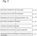
- Fig 3 shows a flow diagram of an embodiment method to determine a filtered cranking signal from the cranking signal.
- the cranking signal comprises N samples 1..N.
- the substeps for obtaining the filtered cranking signal from the cranking signal comprising:
- the coefficient ⁇ is 0.9. and the value c is 0.9b.
- This unique end point (Z, c) of the cranking signal is applied in a window function to obtain an intermediate cranking signal.
- Fig. 9 shows a graphical representation of the cranking signal.
- (X,a) represents a local minimum of the cranking signal 90
- (Y,b) represents a local maximum of the cranking signal
- (Z,c) represents a value c of sample Z, which sample number is determined between X and N in the cranking signal such that the value c equals 0.9 b.
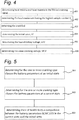
- Fig. 4 shows a flow diagram of an embodiment of the method to determine battery parameters from the filtered cranking signal.
- the substeps to determine the battery parameters comprises: Firstly determining a parameter crankEnd by the substeps:
- M represents the number of samples determined by S-L.
- the state of health of the battery can be based on a comparison of the battery parameters IV, LW, MCV in a historic or initial state and the determined parameters IV, LVV and MCV in the current state for the different cranking type classes from the filtered cranking signal.
- the determined values of these battery parameters can be stored in a table or database in a local memory 13 of the device 10 or in the data base server 18 which can be accessed by the device 10 through the Internet 17.
- An example of battery parameters IV, LVV and MCV are listed in table 1 for 17 cranking type classes.
- Table 1 table of cranking type classes and batteryparameters crankingTypeClass completed IV MCV LVV H1 FALSE H2 FALSE H3 FALSE H4 FALSE 12,17 9,79 8,03 H5 FALSE W1 FALSE W2 FALSE W3 FALSE 12,17 9,92 8,07 W4 TRUE 12,18 9,88 8,13 W5 FALSE C1 FALSE C2 FALSE 11,93 9,68 7,51 C3 TRUE 11,97 9,46 7,81 C4 TRUE 12,04 9,74 7,92 C5 FALSE N1 FALSE 12,13 8,05 9,81 etc.
- the values for IV, MCV and LW in Table 1 can be stored and updated in the data base after the cranking events in the corresponding cranking type class.
- Fig. 5 shows a flow diagram of a first embodiment of the method to determine a state of health from the battery parameters.
- the step of determining the state of health of the battery comprises the substeps:
- C 1 is a constant that can be experimentally determined and its value can be for example 0.8.
- the state of health of the battery is set to poor when the inequality is true.
- an indication of the state of health as poor indicates a high change of battery failure.
- an indication of the state of health as healthy indicates a new or freshly installed battery.
- the battery parameters of the initial state can be obtained from the local memory 13 or the database server 18.
- the device can output the determined state of health
- Fig 6 shows a graphical representation of a 2D-parameter field of the normalized LVV and the normalized MCV.
- Fig. 6 shows a separation line 601 indicating the separation between a healthy state and a poor state of the battery.
- the area including a point 602 above and right of the separation line indicates the healthy state.
- the area including a point 603 below and left of the separation line indicates the poor state.
- Fig. 7 shows a flow diagram of a second embodiment of the method for determining a state of health from the battery parameters.
- the step of determining the state of health of the battery in a cranking type class comprises the substeps:
- Fig. 8 shows a graphical representation of a 2D-parameter field for the unscaled MCV and the unscaled LVV.
- Fig. 8 shows an ellipsoid 801 indicating an area of a healthy state of the battery.
- Combined values of the MCV and the LVV in the lower left corner of the field, for example a point 803 correspond to a poor state of health of the battery.
- a point 802 in Fig. 8 corresponds to a still healthy state.
- step (208) the device can output the determined state of health of the battery as poor indicating a high change of battery failure.
- the present invention can be described as a method and apparatus for determining a state of health of a battery in a vehicle comprising determining (201) a state of charge of the battery; determining (202) a battery temperature, determining a cranking temperature based on the engine coolant temperature, the ambient temperature, the device temperature and the time elapsed since the last trip; obtaining (204) a cranking signal from the battery when the battery is discharged during cranking of a combustion engine of the vehicle; determining (205) one or more cranking type classes based on the determined battery temperature and the determined cranking temperature; determining (206) battery parameters from the cranking signal; determining (207) the state of health of the battery from the battery parameters, a vehicle identifier and historical battery parameters determined in a historic state preceding the current state; and outputting (206) the state of health, wherein determining the battery parameters from the cranking signal comprises applying a window function on the cranking signal to obtain an intermediate cranking signal, filtering the intermediate cranking signal and determining the battery parameters from the filtered cranking signal
Landscapes
- Engineering & Computer Science (AREA)
- Life Sciences & Earth Sciences (AREA)
- Sustainable Development (AREA)
- Sustainable Energy (AREA)
- Power Engineering (AREA)
- Transportation (AREA)
- Mechanical Engineering (AREA)
- Physics & Mathematics (AREA)
- General Physics & Mathematics (AREA)
- Secondary Cells (AREA)
- Tests Of Electric Status Of Batteries (AREA)
Description
- The present invention relates to a method and device for indicating a state of health of a battery in a vehicle. In general, batteries are applied in vehicle for cranking a combustion engine.
- Battery technology comprises a combination of chemistry, material, mechanical and electrical science. An aggregation of these technologies yields to a small electrical-energy producing device, referred to as a battery. In the automotive sector lead acid batteries are used in cranking applications.
- The state of health, SOH, of lead acid batteries is decreasing with age revealing a reduced battery performance. The performance of lead acid batteries is expressed in capacity and peak power delivery.
- The effective performance and therefore the SOH of the battery is gradually decreasing until a cranking failure manifests itself. Batteries can have different failure modes caused by a combination of underlying failure mechanisms. A battery is a closed system and progressing failure mechanisms cannot be observed without the use of invasive methods i.e. to really reveal the battery's SOH the casing has to be opened enabling the internals to be examined which will destroy the battery. Most failures are caused by a combination of different failure mechanisms. Using a non-invasive SOH estimator groups all progressing failure mechanisms together, but enables the SOH to be estimated without destroying the battery. Conventionally, non-invasive SOH estimators are based on the effective capacity and internal resistance of the battery.
- A method and apparatus for indicating a state of health of a battery is known from
US20130046435 . A starting system for an internal combustion engine includes a starter motor and a battery. A method for evaluating the starting system includes detecting a fault associated with the starter motor when a minimum starting system voltage during a cranking event is greater than a threshold minimum starting system voltage determined in relation to an engine acceleration parameter, and detecting a fault associated with the battery when the engine acceleration parameter is less than a minimum threshold for the engine acceleration parameter. - A drawback of the known device and method is that the indication of the state of the battery is not reliable.
- Therefore, there is a need to provide a more efficient method and a device estimating the state of health of the battery.
-
US 6118252A relates to a process for determining the starting capacity of a starter battery of a motor vehicle for which the mean value for the voltage surge during the starting of an internal combustion engine, is determined as a function of mean values for the battery and engine temperatures, compared with the voltage surge values of a characteristic line field which records determined voltage surges as a function of corresponding battery and engine temperatures, a deviation of the actually determined voltage surge from the voltage surge stored in the characteristic line field is determined and compared to a preassigned value, and an indicator or an alarm is triggered as soon as the preassigned value is exceeded. -
US 2015/361941 A1 discloses an internal combustion engine that employs a starting system. A method for evaluating the starting system includes determining a cranking resistance ratio between a starter and a battery of the starting system during engine cranking. The cranking resistance ratio is normalized based upon an operating temperature of the starting system, and the starting system is evaluated based upon the normalized cranking resistance ratio. -
WO 2009/158224 A2 discloses a method for determining a battery's state-of -health. An initial battery voltage is measured at a first voltage drop during an initiation of an engine cranking phase. A battery voltage is monitored during the remainder of the engine cranking phase. A lowest battery voltage is determined during the remainder of the engine cranking phase. A determination is made if a voltage difference between the lowest battery voltage and the initial battery voltage at the initiation of the engine cranking phase is less than a voltage threshold. A low battery state-of-health is identified in response to the voltage difference being less than the voltage threshold. -
WO 2009/158225 A2 discloses a method for determining a state-of-health of a battery in a vehicle-during an engine cranking phase. An engine cranking phase is initiated. Characteristic data is recorded that includes battery voltage data and engine cranking speed data during the engine cranking phase. The characteristic data is provided to a pre-processing unit. The pre-processing unit normalizes the characteristic data for processing within a classifier. The normalized data is input to the classifier for determining the vehicle battery state-of-health. The classifier has a trained state-of-health decision boundary resulting from a plurality of trials in which predetermined characterization data is collected with known classes. The battery state-of- health is classified based on the trained state-of-health decision boundary. -
WO 2014/098837 A1 discloses systems and methods for determining the state of health of a generator battery set and its ability to supply generator starter motor with start-up energy by capturing a profile of voltage across terminals of the battery during a supply of electrical energy from the battery to the starter and comparing the captured voltage profile to a reference voltage profile to determine if a difference between the captured voltage profile and reference voltage profile exceeds an acceptable amount. -
US 6472875 B1 discloses a process for the detection of a defect of an automotive vehicle battery includes analyzing the time dependence of the discharge voltage across the terminals of the battery. This process has the steps of measuring at least two successive values of the discharge voltage of the battery, during the phase of cranking the engine of the automotive vehicle, for at least two consecutive top dead center points, taking a difference of the measured voltage values, and deducing therefrom whether the battery is charged or defective. The process is built into an electronic computer carried on board the automotive vehicle. -
US 6727708 B1 discloses a battery monitoring system. The system comprises a means for acquiring a value representative of a first period of time during which the battery will deliver a sufficient amount of power. The system also comprises a means for measuring a set of parameters comprising a voltage of the battery and a temperature of the battery during a second period of time. The system also comprises a means for predicting whether the battery will deliver the sufficient amount of power during a third period of time less than the first period of time. An output signal is provided if the means for predicting determines that the battery will deliver the sufficient amount of power during the third period of time. A system for determining whether a battery for a vehicle will deliver a sufficient amount of power for a sufficient amount of time is also disclosed. - According to a first aspect, the invention provides a method for determining a state of health of a battery in a vehicle according to
claim 1. - According to the present invention, a method for determining a state of health as defined above is provided, in which the method non-invasive measuring of the cranking signal can be applied. For example, a standardized connection implemented in all European vehicles since 2002 can provide a cranking signal of the battery of the vehicle at a number of instants and during cranking. The cranking signal can be a digital signal obtained via the standardised connection. For example from the on board diagnostic device, OBD.
- The state of charge of the battery can be used to decide whether to continue or to discontinue the present method depending on the obtained state of charge, because it does not make sense to determine the state of health for a discharged or partly discharged battery. The battery temperature can be based on the temperatures provided by an engine management system via the standardized connection directly after a cranking event. For example, an engine coolant temperature, ambient temperature, device temperature; duration of last operation of the combustion engine and time elapsed since the last operation.
- The cranking temperature is based on the engine coolant temperature, the ambient temperature, the device temperature and the time elapsed since the last trip.
- The inventors have acknowledged a high correlation between the voltage values of the battery, the temperature of the engine of the vehicle and the battery. Different cranking type classes can be distinguished based on the determined battery temperature and the cranking temperature. By distinguishing different cranking type classes the estimation of the battery state can be further improved. The battery parameters determined from the cranking signal corresponding to the cranking type class and a vehicle identifier has proven to be reliable state parameters of the battery and enables a reliable determination of the state of health of the battery. According to the invention an intermediate cranking signal is obtained by window function on the cranking signal. The window function is based on a minimum value, a maximum value and a determined unique end point of the cranking signal. The unique endpoint can be obtained based on a local maximum value of the cranking signal. The inventors have realized that the application of this window function provides a consistent intermediate cranking signal this is independent from a user of the car, so that more accurate state parameters of the battery can be obtained. The determined state of health can be displayed or a warning signal can be generated.
- According to an embodiment the historical state of the battery is an initial state of the battery. The initial state can be the state of a new or fresh battery when directly installed in the vehicle.
- According to an embodiment the step of determining the state of health comprises performing a normalized field method on the battery parameters in the initial state and the current state for the determined cranking type class for a certain vehicle identified by the vehicle identifier. The normalized field method is used to determine an area based on a combination of the battery parameters indicating a healthy state of the battery or an area indicating a poor state of the battery. The inventors has realized that this method takes advantage of the interdependency between the battery parameters.
- According to a still further embodiment determining the battery parameters for the cranking type class in the initial state comprises:
- measuring battery parameters measured after each of a plurality of consecutive crank periods;
- determining the battery parameters based on an average of the measured battery parameters. By repeating, in the initial state, these steps the battery parameters corresponding to a set of cranking type classes in the initial state can be obtained.
- In the normalized field method a normalized value can be obtained by using the quotient of the battery parameters in the current state and the battery parameter in the reference state and by selecting two battery parameters from the set of battery parameters and defining a line in the parameter field defined by the selected battery parameters. The battery parameters can be an initial voltage, IV, a lowest voltage value, LVV, and a mean cranking voltage, MCV. These parameters have proven to be the most promising for estimating the state of health of the battery.
- According a still different embodiment the step of determining the state of health comprises
- determining a moving window average of the historical battery parameter of a plurality of historic states in the cranking type class;
- determining a scaled battery parameter based on the battery parameter determined at the current state and the determined moving window average of the historical battery parameter in the cranking type class;
- determining the state of health at the current state from the scaled battery parameters.
- According to a further embodiment determining the state of charge of the battery comprises
- determining, after a resting period of the combustion engine, a resting voltage of the battery;
- determining a reference value for the resting voltage;
- measuring the resting voltage of the battery in the current state after an operating period of the combustion engine;
- determining the state of charge of the battery based on the reference resting voltage value, the measured resting value and the operating period;
- deciding to continue or discontinue the determination of the state of health of the battery depending of the state of charge of the battery. In this way a state of charge can be determined after a resting period of the battery after an operation period of the vehicle. This steps prevents performing the further steps of the method when the state of charge of the battery is insufficient, for example when the battery is not recharged completely after a short operation or short trip of the vehicle.
- According to a further embodiment the battery temperature is based on an engine coolant temperature, ambient temperature, device temperature; duration of last operation of the combustion engine and time elapsed since the last operation. In this way a more reliable estimation of the battery temperature can be obtained.
- According to the claimed invention obtaining the intermediate cranking signal based on the cranking signal and a window function comprises determining a minimum of the cranking signal; determining a maximum of the cranking signal between the first sample of the cranking signal and the determined minimum of the cranking signal; determining an endpoint of the cranking signal that corresponds to a sample number corresponding to a value that is equal to a predetermined coefficient multiplied by the determined maximum and the sample number is larger than the sample number corresponding to the determined minimum; wherein the window function is arranged to pass the samples between the determined maximum and the determined end point of the cranking signal and obtaining the intermediate cranking signal. The coefficient can be determined experimentally. A practical value is 0.9. An advantage of the application of determined end point of the cranking signal and the application of this window function is that a consistent intermediate cranking signal is obtained that is independent from the user of the car.
- According to an embodiment the filtering of the intermediate signal comprises splitting the intermediate cranking signal in a first part comprising samples in the range between a maximum and a minimum and a second part comprising samples in the range between the minimum and an endpoint, filtering the first and second parts by a first and second digital filter respectively; and obtaining the filtered cranking signal by concatenating the filtered first and second parts. By splitting the intermediate cranking signal, different digital filters can be applied on the first and second parts the different digital filters can be individually optimized depending on the characteristics of the first and second parts and the filtered cranking signal.
According to a still further embodiment the first and second digital filter respectively, comprises a Saviki-Golay filter, wherein a frame length and a polynomial order of the respective filters can be selected differently depending on the characteristics of respective first and second part. The Saviky-Golay filter is a well-known digital filter for the person skilled in the art. The frame length and polynomial order can be differently selected depending on the variation of the values in the first and second part. - According to a second aspect, the invention provides a device for determining a state of health of a battery in a vehicle according to
claim 13. - The present invention will be discussed in more detail below, with reference to the attached drawings, in which
-
Fig. 1 shows an embodiment of an apparatus for determining a state of health of a battery; -
Fig. 2 shows a flow diagram of an embodiment of the method; -
Fig. 3 shows a flow diagram of an embodiment of the method to determine a cranking signal; -
Fig. 4 shows a flow diagram of an embodiment of the method to determine battery parameters from the filtered cranking signal; -
Fig. 5 shows a flow diagram of a first embodiment of the method to determine a state of health from the battery parameters; -
Fig. 6 shows a graphical representation of a two-dimensional normalized parameter field; -
Fig. 7 shows a flow diagram of a second embodiment of the method for determining a state of health from the battery parameters; -
Fig. 8 shows a graphical representation of a two-dimensional non-scaled parameter field; and -
Fig. 9 shows a graphical representation of a cranking signal. -
Fig. 1 is a block diagram of an internal structure of adevice 10 or system comprising a user's computer in accordance with an exemplary embodiment of the present invention for determining a state of health of abattery 2 in avehicle 1. The vehicle is provided with anengine 3 including a crank unit, abattery 2, anengine management system 4 and a vehicle communication device 5. The vehicle communication device 5 may comprise an on board diagnostic, device, OBD. The OBD can be connected via a Bluetooth or Wi-Fi device to thedevice 10.
Thedevice 10 can be a personal computer, a smartphone, laptop or any other type of microprocessor based device. Thedevice 10 may comprise aprocessor 11, aninput device 12, astorage device 13, thestorage device 13 can be a temporary storage device or permanent storage device and afirst communication device 15 for connecting to the OBD 5. Thefirst communication device 15 may include a modem, network interface card, or any other device able to transmit and receive signals to the vehicle communication device 5, for example Bluetooth or Wi-Fi. Theinput device 12 can be a key board, mouse, pen operated device and any other input device that provides input from a user. The device can further comprise asecond communication device 16 and anoutput device 14. Thesecond communication device 16 may include a modem, network interface card, or any other device able to communicate to theserver 18 via theInternet 17. Theoutput device 14 may be a monitor, speakers, printer or any other device that provides tangible output to a user. The temporary storage device may include RAM, caches, and any other volatile storage medium that temporarily holds data while processing it. The permanent storage device may include a solid state drive, hard drive, CD-ROM drive, tape drive, removable storage disk, or any other nonvolatile data storage medium. The temporality and permanent storage devices can store one or more of the determined parameters and values obtained during operation of the methods, described hereinafter. -
Fig. 2 shows a flow diagram according to an embodiment of the method for determining a state of health of the battery. In step 201 a state of charge of the battery is determined. According to an embodiment the state of charge can be determined by obtaining the open circuit voltage, OCV, of the battery after a predetermined rest period, wherein the vehicle is shut down and parked. The rest period can be for example 30 minutes. The thus obtained value proves to be a more accurate estimate of the OCV. The obtained value of the open circuit voltage is hereinafter called the rest value, RV. The RV is unique for a battery-vehicle combination. From the RV value a reference value can be obtained. A deviation from the reference value may indicate an insufficient state of charge of the battery. - Alternatively, according to an embodiment determining the state of charge of the battery may comprise the substeps of:
Measuring the values of the resting voltage of the battery at plurality of instants at a fixed time interval in an initial state and a current state. - Determining a derivative from the plurality of measured values in the initial state and the current state.
- Determining a resting voltage derivative deviation based on the derivatives of the measured values in the initial state and the derivatives of the measured values in the current state;
wherein the determining the state of charge is based on the resting voltage derivative deviations. - According to an embodiment the method of determining the state of health can be discontinued and a message can be output on the
display 14, when the determined state of charge of the battery is poor and a reliable state of health of the battery cannot be obtained. - In step 202 a battery temperature can be obtained. According to an embodiment the battery temperature is based on a combination of the engine coolant temperature, ambient temperature, device temperature a duration of last operation of a combustion engine, and time elapsed since last trip. These values can be obtained from the engine management unit via the communication interface and/or the OBD 5.
- In step 203 a cranking temperature can be determined based on the engine coolant temperature, the ambient temperature, the device temperature and the time elapsed since the last trip. These values can also be obtained from the engine management unit via the communication interface and/or the OBD 5.
- In step 204 a cranking signal can be obtained and can be a digital signal obtained during a cranking period by sampling the voltage of the battery, when the battery is discharged by the crank unit during one or more revolutions of the crank unit in the combustion engine during the cranking period. The cranking period is for example 1 sec. The sample frequency can be for example 200 Hz. So, according to this embodiment the cranking signal comprises 200 samples. The cranking signal can also be obtained from the communication device and/or the OBD.
- In
step 205 one or more cranking type classes of the battery are determined based on the determined battery temperature and the determined cranking temperature. The advantage of using cranking type classes is that the inventors recognized that the cranking type classes may define sets of reference battery parameters that are specific for each vehicle, the battery temperature and cranking temperature. A cranking temperature signal can also obtained from the communication device or the OBD. The cranking type classes can be selected on basis of the determined battery temperature and determined cranking temperature. The number of cranking type classes can be for example 17. - In
step 206 the battery parameters, for example the lowest voltage value, LVV, and the mean cranking voltage, MCV are obtained from the cranking signals corresponding to one or more cranking type classes. - According to an embodiment the step of determining the battery parameters for the one or more cranking type classes in the initial state comprises determining battery parameters after each of a plurality of consecutive crank periods from the cranking signals; and determining the battery parameters based on an average of the measured battery parameters. These steps can be repeated for the all the cranking type classes.
- According to the invention the step of determining battery parameters from the obtained cranking signal comprises the substeps of determining an intermediate cranking signal from the cranking signal and a filtered cranking signal from the intermediate cranking signal and determining the battery parameters from the filtered cranking signal.
-
Fig 3 shows a flow diagram of an embodiment method to determine a filtered cranking signal from the cranking signal. In this description the cranking signal comprisesN samples 1..N. - The substeps for obtaining the filtered cranking signal from the cranking signal comprising:
- Determining (301) a local minimum (X, a) in the cranking signal; wherein X represents a number of the sample in the cranking signal and a represents a value of the sample.
- Determining (302) a local maximum (Y, b) in the cranking signal, wherein Y represents the sample number and satisfies 1 < Y< X and b represents the value b of the sample;
- Determining (303) a unique end point (Z, c), wherein Z represents a sample number between X and N in the cranking signal that corresponds to the number of the sample which value c equals a predetermined coefficient α multiplied by the value b of the determined local maximum.
- In an embodiment the coefficient α is 0.9. and the value c is 0.9b. This unique end point (Z, c) of the cranking signal is applied in a window function to obtain an intermediate cranking signal. An advantage if this unique end point (Z, c) is that it is independent of the user of the car or engine.
- Determining (304) an intermediate cranking signal of the samples Y to the endpoint Z of the cranking signal. The resulting intermediate cranking signal is the result of the window function applied on the cranking signal, wherein the window function transfers the samples Y to Z.
- The intermediated cranking signal is then filtered by:
- Splitting (305) the Z-Y samples of the intermediate cranking signal in a first part of samples Y to X and a second part of samples X to Z.
- Filtering (306) the first part by a first digital filter and the second part by a second digital filter. In an embodiment the digital filters can be a Saviki-Golay filter, as is well-known for the skilled person, in the respective Saviki-Golay filter the frame length and polynomial order can be differently selected depending on the variation of the values in the first and second part of the intermediate cranking signal.
- Determining (307) the filtered cranking signal by concatenating the filtered second part after the filtered first part.
-
Fig. 9 shows a graphical representation of the cranking signal. In the graph (X,a) represents a local minimum of the crankingsignal 90, (Y,b) represents a local maximum of the cranking signal, and (Z,c) represents a value c of sample Z, which sample number is determined between X and N in the cranking signal such that the value c equals 0.9 b. -
Fig. 4 shows a flow diagram of an embodiment of the method to determine battery parameters from the filtered cranking signal. The substeps to determine the battery parameters comprises:
Firstly determining a parameter crankEnd by the substeps: - Determining (401) local minima and local maxima in the filtered cranking signal.
- Determining (402) the local maximum (K, Maxlocal) having the highest sample number K from the local maxima.
- Determining (403) the crankEnd as the sample number S corresponding to a sample (S, d) in the filtered cranking signal wherein S is between K and Z and d equals Maxlocal.
- determining at least one or more of the determined local maxima (i,maxi) for which the sample number i is smaller than X. This number can be for example 3.
- determining (404) the initial value, IV, from the average of the one or more determined local maxima maxi values.
- Determining (405) the lowestValleyVoltage, LW as the lowest local minimum (L, Minlocal) from the filtered cranking signal.
- Wherein M represents the number of samples determined by S-L.
In this way the filtered cranking signal with a user independent crank end can be determined. - According to an embodiment the state of health of the battery can be based on a comparison of the battery parameters IV, LW, MCV in a historic or initial state and the determined parameters IV, LVV and MCV in the current state for the different cranking type classes from the filtered cranking signal. The determined values of these battery parameters can be stored in a table or database in a
local memory 13 of thedevice 10 or in thedata base server 18 which can be accessed by thedevice 10 through theInternet 17.
An example of battery parameters IV, LVV and MCV are listed in table 1 for 17 cranking type classes.Table 1 table of cranking type classes and batteryparameters crankingTypeClass completed IV MCV LVV H1 FALSE H2 FALSE H3 FALSE H4 FALSE 12,17 9,79 8,03 H5 FALSE W1 FALSE W2 FALSE W3 FALSE 12,17 9,92 8,07 W4 TRUE 12,18 9,88 8,13 W5 FALSE C1 FALSE C2 FALSE 11,93 9,68 7,51 C3 TRUE 11,97 9,46 7,81 C4 TRUE 12,04 9,74 7,92 C5 FALSE N1 FALSE 12,13 8,05 9,81 etc. -
Fig. 5 shows a flow diagram of a first embodiment of the method to determine a state of health from the battery parameters. According to this embodiment the step of determining the state of health of the battery comprises the substeps: - Determining (501) for the at least one or more cranking type classes the battery parameters at an initial state of the battery for the at least one or more cranking type classes according to steps 200-204.
- Determining (502) for the at least one or more cranking type classes the battery parameters at a current state of the battery for the at least one or more cranking type classes according to steps 200-204.
- Determining (503) the state of health of the battery from a comparison of the determined battery parameters IV, MCV, LVV in the initial state and the parameters IV, MCV, LVV in the current state by applying a normalized field method on the normalized battery parameters in the determined cranking type class, wherein the normalized battery parameters are based on the battery parameters MCV, LW in the current state and the battery parameters MCV, LVV in the initial state.

- Determining (504) the state of health of the battery according to the inequality
- Wherein C1 is a constant that can be experimentally determined and its value can be for example 0.8.
- The state of health of the battery is set to poor when the inequality is true. In this application an indication of the state of health as poor indicates a high change of battery failure. When the inequality is false the state of health of the battery is set to healthy. In this application an indication of the state of health as healthy indicates a new or freshly installed battery. The battery parameters of the initial state can be obtained from the
local memory 13 or thedatabase server 18. - In a next step (208) of the method the device can output the determined state of health
-
Fig 6 shows a graphical representation of a 2D-parameter field of the normalized LVV and the normalized MCV.Fig. 6 shows aseparation line 601 indicating the separation between a healthy state and a poor state of the battery. The area including apoint 602 above and right of the separation line indicates the healthy state. The area including apoint 603 below and left of the separation line indicates the poor state. -
Fig. 7 shows a flow diagram of a second embodiment of the method for determining a state of health from the battery parameters. According to this embodiment the step of determining the state of health of the battery in a cranking type class comprises the substeps: - Determining (701) a moving window average of the historical battery parameter LVV and MCV for a current state based on historical battery parameter LVV and MCV corresponding to historic states or previous cranks stored in the
local memory 13, or that can be retrieved via theInternet 17 from thedata base server 18. In an embodiment, the moving window average can be based on 30 stored historic states by a moving window of a width spanning 20 states, in the cranking type class from a first historic state N= -30 to a second historic state N= -10 before the current state in a the cranking type class according to formula
- Determining (702) a scaled battery parameter based on the battery parameter determined at the current state and the determined moving window average of the historical battery parameter in the cranking type class.

- Determining (703) the state of health of the battery from the scaled LVV and the scaled MCV according to the inequalities

The state of health of the battery is poor when both inequalities are true. -
Fig. 8 shows a graphical representation of a 2D-parameter field for the unscaled MCV and the unscaled LVV.Fig. 8 shows anellipsoid 801 indicating an area of a healthy state of the battery. Combined values of the MCV and the LVV in the lower left corner of the field, for example apoint 803 correspond to a poor state of health of the battery. Apoint 802 inFig. 8 corresponds to a still healthy state. - In step (208) the device can output the determined state of health of the battery as poor indicating a high change of battery failure.
- The present invention can be described as a method and apparatus for determining a state of health of a battery in a vehicle comprising determining (201) a state of charge of the battery; determining (202) a battery temperature, determining a cranking temperature based on the engine coolant temperature, the ambient temperature, the device temperature and the time elapsed since the last trip; obtaining (204) a cranking signal from the battery when the battery is discharged during cranking of a combustion engine of the vehicle; determining (205) one or more cranking type classes based on the determined battery temperature and the determined cranking temperature; determining (206) battery parameters from the cranking signal; determining (207) the state of health of the battery from the battery parameters, a vehicle identifier and historical battery parameters determined in a historic state preceding the current state; and outputting (206) the state of health, wherein determining the battery parameters from the cranking signal comprises applying a window function on the cranking signal to obtain an intermediate cranking signal, filtering the intermediate cranking signal and determining the battery parameters from the filtered cranking signal
- In this way a reliable indication can be obtained from the state of health of the battery in the vehicle.
- The present invention has been described above with reference to a number of exemplary embodiments as shown in the drawings. Modifications and alternative implementations of some parts or elements are possible, and are included in the scope of protection as defined in the appended claims.
- In the foregoing description of the figures, the invention has been described with reference to specific embodiments thereof. It will, however, be evident that various modifications and changes may be made thereto without departing from the scope of the invention as defined in the attached claims.
- In addition, many modifications may be made to adapt a particular situation or material to the teachings of the invention without departing from the scope thereof. Therefore, it is intended that the invention not be limited to the particular embodiments disclosed, but that the invention will include all embodiments falling within the scope of the appended claims.
- In particular, combinations of specific features of various aspects of the invention may be made. An aspect of the invention may be further advantageously enhanced by adding a feature that was described in relation to another aspect of the invention.
- It is to be understood that the invention is limited by the annexed claims only. In this document and in its claims, the verb "to comprise" and its conjugations are used in their non-limiting sense to mean that items following the word are included, without excluding items not specifically mentioned. In addition, reference to an element by the indefinite article "a" or "an" does not exclude the possibility that more than one of the element is present, unless the context clearly requires that there be one and only one of the elements. The indefinite article "a" or "an" thus usually means "at least one".

Claims (13)
- A method for determining a state of health of a battery in a vehicle provided with a combustion engine, comprising the steps ofa) determining (201) a state of charge of the battery;b) determining (202) a battery temperature;c) determining (203) a cranking temperatured) obtaining (204) a cranking signal comprising a plurality of samples from the battery when the battery is discharged during cranking of the combustion engine;e) determining (205) one or more cranking type classes based on the determined battery temperature and the determined cranking temperature;f) determining (206) battery parameters from the cranking signal corresponding to the determined one or more cranking type classes;g) determining (207) the state of health of the battery for the at least one or more cranking type classes from the battery parameters determined corresponding to the cranking type class in a current state, a vehicle identifier and historical battery parameters corresponding to the one or more cranking type classes determined in a historic state preceding the current state; andh) outputting (208) the state of health;wherein determining the battery parameters from the cranking signal comprises obtaining an intermediate cranking signal;
filtering the intermediate cranking signal; and
determining the battery parameters from the filtered cranking signal;
the method being characterized by: the determining a cranking temperature is based on an engine coolant temperature, an ambient temperature, an engine temperature and a time elapsed since the last trip; and the obtaining an intermediate cranking signal is based on the cranking signal and a window function and comprises:determining (301) a minimum of the cranking signal;
determining (302) a maximum of the cranking signal between the first sample of the cranking signal and the determined minimum of the cranking signal;determining (303) an endpoint of the cranking signal that corresponds to a sample number corresponding to a value that is equal to a predetermined coefficient multiplied by the determined maximum and the sample number is larger than the sample number corresponding to the determined minimum;wherein the window function is arranged to pass the samples between the determined maximum and the determined end point of the cranking signal and obtaining (304) the passed samples as the intermediate cranking signal. - The method according to claim 1, wherein the historic state corresponds to an initial state of the battery.
- The method according to claim 2, wherein determining the state of health comprises performing a normalized field method on the battery parameters in the initial state and the current state in the cranking type class, wherein an area of a poor state of the battery is based on two normalized battery parameters.
- The method according to claims 2 and 3, wherein determining the battery parameters for the one or more cranking type classes in the initial state comprises:a) determining the battery parameters after each of a plurality of consecutive crank periods;b) determining the initial battery parameters based on an average of the measured battery parameters; andc) repeating steps 4.a) and 4.b) for each of the one or more cranking type classes.
- The method according to claim 4, wherein the battery parameters comprises an initial voltage, IV, a lowest voltage value, LVV, and a mean cranking voltage, MCV.
- The method according to claim 1, wherein determining the state of health comprises determining (701) a moving window average of the historical battery parameter of a plurality of historic states in the cranking type class;
determining (702) a scaled battery parameter based on the battery parameter determined at an current state and the determined moving window average of the historical battery parameter in the cranking type class; and
determining (703) the state of health at the current state from the scaled battery parameters. - The method according to claim 6, wherein the moving window average of the historic battery parameter is determined from a first historic state N-30 to a second historic state N-10 before the current state N in the cranking type class.
- The method according to claims 6 or 7, wherein the battery parameters comprises a lowest voltage value, LVV and a mean cranking voltage, MCV.
- The method of claim 1 wherein determining the state of charge of the battery comprisesdetermining, after a resting period of the combustion engine, a resting voltage of the battery;determining a reference value for the resting voltage;measuring the resting voltage of the battery in a current state after an operating period of the combustion engine;determining the state of charge of the battery based on the reference resting voltage value, the measured resting value and the operating period;deciding to continue or discontinue the determination of the state of health of the battery depending of the state of charge of the battery.
- The method of claim 1, wherein determining the battery temperature is based on an engine coolant temperature, ambient temperature, engine temperature; duration of last operation of the combustion engine and time elapsed since the last operation.
- The method of claim 1, wherein the filtering of the intermediate cranking signal comprisessplitting (305) the intermediate cranking signal in a first part comprising samples in the range between a maximum and a minimum and a second part comprising samples in the range between the minimum and an endpoint of the intermediate cranking signal;filtering (06) the first and second parts by a first and second digital filter respectively; andobtaining(307) the filtered cranking signal by concatenating the filtered first and second parts.
- The method of claim 11, wherein the first and second digital filter comprises a Saviki-Golay filter respectively, wherein a frame length and a polynomial order of the respective filters are different based on the characteristics of respective first and second parts.
- A device for determining a state of health of a battery (2) in a vehicle (1) provided with a combustion engine comprising
a storage device (13),
an input device (12);
an output device (14) comprising a display;
a communication device (15) arranged to communicate to a control system of the vehicle to receive an ambient temperature; an open voltage of the battery; an engine coolant temperature, and a cranking signal comprising a plurality of samples from the battery when the battery is discharged during cranking of a combustion engine of the vehicle and
a controller (11) arranged toa) determine a state of charge of the battery;b) determine a battery temperature;c) determine a cranking temperature;e) determine one or more cranking type classes based on the determined battery temperature and the determined cranking temperature;f) determine battery parameters from the cranking signal corresponding to the determined one or more cranking type classes;g) determine the state of health of the battery for at least one or more cranking type classes, from the battery parameters determined corresponding to the cranking type class in a current state, a vehicle identifier and historical battery parameters corresponding to the one or more cranking type classes determined in a historic state preceding the current state; andh) output the state of health through the output device;wherein the controller is further arranged to determine the battery parameters from the cranking signal by obtaining an intermediate cranking signal;
filtering the intermediate cranking signal; and
determining the battery parameters from the filtered cranking signal; characterized by:the controller being arranged to determine the cranking temperature based on the engine coolant temperature,the ambient temperature, the engine temperature and the time elapsed since the last trip;wherein the controller is arranged to determine the battery parameters from the cranking signal by obtaining the intermediate cranking signal based on the cranking signal and a window function comprising:determining a minimum of the cranking signal;determining a maximum of the cranking signal between the first sample of the cranking signal and the determined minimum of the cranking signal;determining an endpoint of the cranking signal that corresponds to a sample number corresponding to a value that is equal to a predetermined coefficient multiplied by the determined maximum and the sample number is larger than the sample number corresponding to the determined minimum; whereinthe window function is arranged to pass the samples between the determined maximum and the determined end point of the cranking signal and obtaining the passed samples as the intermediate cranking signal.
Applications Claiming Priority (2)
| Application Number | Priority Date | Filing Date | Title |
|---|---|---|---|
| NL2019831A NL2019831B1 (en) | 2017-10-30 | 2017-10-30 | Method and apparatus for indicating a state of health of a battery |
| PCT/NL2018/050722 WO2019088830A1 (en) | 2017-10-30 | 2018-10-30 | Method and apparatus for indicating a state of health of a battery |
Publications (2)
| Publication Number | Publication Date |
|---|---|
| EP3704505A1 EP3704505A1 (en) | 2020-09-09 |
| EP3704505B1 true EP3704505B1 (en) | 2021-08-04 |
Family
ID=60382569
Family Applications (1)
| Application Number | Title | Priority Date | Filing Date |
|---|---|---|---|
| EP18812383.0A Active EP3704505B1 (en) | 2017-10-30 | 2018-10-30 | Method and apparatus for indicating a state of health of a battery |
Country Status (6)
| Country | Link |
|---|---|
| US (1) | US11203273B2 (en) |
| EP (1) | EP3704505B1 (en) |
| CN (1) | CN111373275B (en) |
| ES (1) | ES2894845T3 (en) |
| NL (1) | NL2019831B1 (en) |
| WO (1) | WO2019088830A1 (en) |
Families Citing this family (14)
| Publication number | Priority date | Publication date | Assignee | Title |
|---|---|---|---|---|
| EP4708233A3 (en) | 2018-02-08 | 2026-05-06 | GEOTAB Inc. | Telematically monitoring a condition of an operational vehicle component |
| US11731867B2 (en) * | 2019-05-28 | 2023-08-22 | Vehicle Service Group, Llc | System for vehicle lift monitoring and prognostics |
| KR102842049B1 (en) * | 2019-06-28 | 2025-08-04 | 주식회사 엘지에너지솔루션 | Apparatus and method for detecting poor battery cell |
| EP3786904B1 (en) * | 2019-08-27 | 2025-02-26 | GEOTAB Inc. | Method for telematically providing vehicle component rating |
| FR3101430B1 (en) * | 2019-09-27 | 2021-09-03 | Continental Automotive | Method for estimating the aging of a vehicle battery |
| EP3835115A1 (en) * | 2019-12-12 | 2021-06-16 | Permobil AB | Method of estimating the remaining driving distance available from a charge for a powered mobility device |
| CN112744087B (en) | 2020-04-08 | 2022-02-25 | 长城汽车股份有限公司 | Ambient temperature determination method, motor controller, control system, and storage medium |
| CN111873999B (en) * | 2020-07-16 | 2021-12-31 | 上海星融汽车科技有限公司 | Vehicle storage battery electric quantity monitoring system and vehicle thereof |
| EP4246158B1 (en) * | 2022-03-15 | 2024-09-04 | Ningbo Geely Automobile Research & Development Co. Ltd. | A method for estimating battery supply voltage |
| CN114646888B (en) * | 2022-03-17 | 2025-09-09 | 彩虹无线(北京)新技术有限公司 | Assessment method and system for capacity fading of power battery |
| CN114843558B (en) * | 2022-05-20 | 2023-07-21 | 上海捷氢科技股份有限公司 | Method and device for determining fuel cell operating characteristics |
| CN115308629B (en) * | 2022-08-23 | 2024-08-13 | 中国第一汽车股份有限公司 | Method and device for testing battery performance, storage medium and electronic equipment |
| CN115635882B (en) * | 2022-11-07 | 2024-11-19 | 上海机动车检测认证技术研究中心有限公司 | Power battery abnormality evaluation method, evaluation apparatus, and computer-readable storage medium |
| CN116500465B (en) * | 2023-05-10 | 2025-06-17 | 赛力斯汽车有限公司 | Battery monitoring method and system based on automobile battery parameters |
Family Cites Families (22)
| Publication number | Priority date | Publication date | Assignee | Title |
|---|---|---|---|---|
| FR2769095B1 (en) * | 1997-10-01 | 1999-11-26 | Siemens Automotive Sa | METHOD FOR DETECTING THE FAILURE OF A MOTOR VEHICLE BATTERY |
| DE19750309A1 (en) * | 1997-11-13 | 1999-05-20 | Vb Autobatterie Gmbh | Method for determining the starting ability of the starter battery of a motor vehicle |
| US6469512B2 (en) * | 2000-01-12 | 2002-10-22 | Honeywell International Inc. | System and method for determining battery state-of-health |
| US6369578B1 (en) * | 2001-06-05 | 2002-04-09 | Delphi Technologies, Inc. | State of health for automotive batteries |
| US6727708B1 (en) * | 2001-12-06 | 2004-04-27 | Johnson Controls Technology Company | Battery monitoring system |
| DE10394007T5 (en) * | 2002-12-31 | 2006-02-02 | Midtronics, Inc., Willowbrook | Apparatus and method for predicting the remaining discharge time of a battery |
| US7545109B2 (en) * | 2006-12-22 | 2009-06-09 | Gm Global Technology Operations, Inc. | Method and apparatus for monitoring an electrical energy storage device |
| US7983862B2 (en) * | 2008-04-22 | 2011-07-19 | GM Global Technology Operations LLC | Battery state-of-health monitoring system and method |
| US8972213B2 (en) * | 2008-06-27 | 2015-03-03 | GM Global Technology Operations LLC | Pattern recognition approach to battery diagnosis and prognosis |
| US8111037B2 (en) * | 2008-06-27 | 2012-02-07 | GM Global Technology Operations LLC | Method for battery state-of-health monitoring using battery voltage during vehicle starting |
| US8212527B2 (en) * | 2008-07-29 | 2012-07-03 | GM Global Technology Operations LLC | Method and apparatus for telematics-based vehicle no-start prognosis |
| US7743649B1 (en) * | 2008-12-18 | 2010-06-29 | Gm Global Technology Operations, Inc. | Cranking capability estimation for a vehicular starting system |
| US20110082621A1 (en) * | 2009-10-02 | 2011-04-07 | Eric Berkobin | Method and system for predicting battery life based on vehicle battery, usage, and environmental data |
| KR20120004670A (en) * | 2010-07-07 | 2012-01-13 | 인셀스(주) | Car battery sensor |
| US8818611B2 (en) | 2011-08-15 | 2014-08-26 | GM Global Technology Operations LLC | Method and apparatus to evaluate a starting system for an internal combustion engine |
| US9086462B2 (en) * | 2012-08-15 | 2015-07-21 | GM Global Technology Operations LLC | Systems and methods for battery parameter estimation |
| WO2014098837A1 (en) * | 2012-12-19 | 2014-06-26 | Schneider Electric USA, Inc. | Battery voltage profile monitoring during generator start |
| US9404466B2 (en) * | 2014-06-14 | 2016-08-02 | GM Global Technology Operations LLC | Method for evaluating an engine starting system |
| GB2537612B (en) * | 2015-04-20 | 2018-05-23 | Trakm8 Ltd | Monitoring the health of a vehicle battery |
| US9816475B1 (en) * | 2016-05-11 | 2017-11-14 | Cooper Technologies Company | System and method for maximizing short-term energy storage in a supercapacitor array for engine start applications |
| TWI622780B (en) * | 2016-11-28 | 2018-05-01 | Dhc Specialty Corp | Asymmetric battery detection device |
| US10144306B2 (en) * | 2017-01-18 | 2018-12-04 | Ford Global Technologies, Llc | Battery health evaluation |
-
2017
- 2017-10-30 NL NL2019831A patent/NL2019831B1/en not_active IP Right Cessation
-
2018
- 2018-10-30 ES ES18812383T patent/ES2894845T3/en active Active
- 2018-10-30 EP EP18812383.0A patent/EP3704505B1/en active Active
- 2018-10-30 CN CN201880070598.8A patent/CN111373275B/en active Active
- 2018-10-30 WO PCT/NL2018/050722 patent/WO2019088830A1/en not_active Ceased
- 2018-10-30 US US16/759,850 patent/US11203273B2/en active Active
Also Published As
| Publication number | Publication date |
|---|---|
| WO2019088830A1 (en) | 2019-05-09 |
| EP3704505A1 (en) | 2020-09-09 |
| US20200331359A1 (en) | 2020-10-22 |
| US11203273B2 (en) | 2021-12-21 |
| CN111373275A (en) | 2020-07-03 |
| NL2019831B1 (en) | 2019-05-08 |
| ES2894845T3 (en) | 2022-02-16 |
| CN111373275B (en) | 2023-05-26 |
Similar Documents
| Publication | Publication Date | Title |
|---|---|---|
| EP3704505B1 (en) | Method and apparatus for indicating a state of health of a battery | |
| KR102837694B1 (en) | Battery diagnosis apparatus, battery diagnosis method, battery pack, and vehicle including the same | |
| CN102656469B (en) | A kind of method and equipment being arranged on the battery efficiency in vehicle for test constantly | |
| JP6026120B2 (en) | Secondary battery internal resistance calculation device and internal resistance calculation method thereof, secondary battery abnormality detection device and abnormality detection method thereof, secondary battery degradation estimation device and degradation estimation method thereof | |
| US20090146664A1 (en) | Battery state of health monitoring system and method | |
| CN100575979C (en) | Method for predicting the remaining life of an electrical energy store | |
| US20220140617A1 (en) | Drooping cell detection and state of cell health monitoring | |
| JPWO2016129248A1 (en) | Secondary battery charge state estimation device and charge state estimation method | |
| JP2018147680A (en) | Temperature abnormality determination device, temperature abnormality determination method, and computer program | |
| JP2025502294A (en) | Battery diagnostic device, battery diagnostic method, battery pack, and automobile | |
| CN117849629A (en) | Battery lithium deposition detection method, device and electronic equipment | |
| CN116125300B (en) | A method, apparatus, electronic device, and storage medium for monitoring abnormalities in a battery pack. | |
| HK40037502A (en) | Method and apparatus for indicating a state of health of a battery | |
| HK40037502B (en) | Method and apparatus for indicating a state of health of a battery | |
| EP3835800B1 (en) | Diagnosis of energy storage systems in operation | |
| CN113408739A (en) | Method, device and equipment for monitoring temperature of stator and storage medium | |
| EP4678457A1 (en) | Electric vehicle charging device for safely and efficiently charging electric vehicle by being equipped with electric vehicle fire prevention function and battery performance evaluation function, and method using same | |
| CN119575200A (en) | A battery capacity correction method suitable for intermittent data loss scenarios | |
| CN117668498A (en) | Pump health assessment method based on reliability distribution and anomaly detection | |
| CN116930763A (en) | Method for detecting residual capacity of battery based on rain flow counting method and application | |
| WO2022089846A1 (en) | A method to monitor battery health of a vehicle | |
| CN116794548A (en) | Battery fault early warning and diagnosing method | |
| US20250172628A1 (en) | Method and device for detecting a failure of a lithium-ion battery cell | |
| CN118033465B (en) | Method and device for identifying battery self-discharge abnormality, vehicle and storage medium | |
| CN113009363A (en) | Method and apparatus for measuring ohmic resistance of battery |
Legal Events
| Date | Code | Title | Description |
|---|---|---|---|
| STAA | Information on the status of an ep patent application or granted ep patent |
Free format text: STATUS: UNKNOWN |
|
| STAA | Information on the status of an ep patent application or granted ep patent |
Free format text: STATUS: THE INTERNATIONAL PUBLICATION HAS BEEN MADE |
|
| PUAI | Public reference made under article 153(3) epc to a published international application that has entered the european phase |
Free format text: ORIGINAL CODE: 0009012 |
|
| STAA | Information on the status of an ep patent application or granted ep patent |
Free format text: STATUS: REQUEST FOR EXAMINATION WAS MADE |
|
| 17P | Request for examination filed |
Effective date: 20200414 |
|
| AK | Designated contracting states |
Kind code of ref document: A1 Designated state(s): AL AT BE BG CH CY CZ DE DK EE ES FI FR GB GR HR HU IE IS IT LI LT LU LV MC MK MT NL NO PL PT RO RS SE SI SK SM TR |
|
| AX | Request for extension of the european patent |
Extension state: BA ME |
|
| DAV | Request for validation of the european patent (deleted) | ||
| DAX | Request for extension of the european patent (deleted) | ||
| GRAP | Despatch of communication of intention to grant a patent |
Free format text: ORIGINAL CODE: EPIDOSNIGR1 |
|
| STAA | Information on the status of an ep patent application or granted ep patent |
Free format text: STATUS: GRANT OF PATENT IS INTENDED |
|
| RIC1 | Information provided on ipc code assigned before grant |
Ipc: B60L 58/16 20190101ALI20210224BHEP Ipc: B60L 58/10 20190101ALI20210224BHEP Ipc: G01R 31/392 20190101AFI20210224BHEP |
|
| INTG | Intention to grant announced |
Effective date: 20210315 |
|
| REG | Reference to a national code |
Ref country code: HK Ref legal event code: DE Ref document number: 40037502 Country of ref document: HK |
|
| GRAS | Grant fee paid |
Free format text: ORIGINAL CODE: EPIDOSNIGR3 |
|
| GRAA | (expected) grant |
Free format text: ORIGINAL CODE: 0009210 |
|
| STAA | Information on the status of an ep patent application or granted ep patent |
Free format text: STATUS: THE PATENT HAS BEEN GRANTED |
|
| AK | Designated contracting states |
Kind code of ref document: B1 Designated state(s): AL AT BE BG CH CY CZ DE DK EE ES FI FR GB GR HR HU IE IS IT LI LT LU LV MC MK MT NL NO PL PT RO RS SE SI SK SM TR |
|
| REG | Reference to a national code |
Ref country code: GB Ref legal event code: FG4D |
|
| REG | Reference to a national code |
Ref country code: AT Ref legal event code: REF Ref document number: 1417508 Country of ref document: AT Kind code of ref document: T Effective date: 20210815 |
|
| REG | Reference to a national code |
Ref country code: CH Ref legal event code: EP |
|
| REG | Reference to a national code |
Ref country code: DE Ref legal event code: R096 Ref document number: 602018021380 Country of ref document: DE |
|
| REG | Reference to a national code |
Ref country code: IE Ref legal event code: FG4D |
|
| REG | Reference to a national code |
Ref country code: NL Ref legal event code: FP |
|
| REG | Reference to a national code |
Ref country code: SE Ref legal event code: TRGR |
|
| REG | Reference to a national code |
Ref country code: LT Ref legal event code: MG9D |
|
| PG25 | Lapsed in a contracting state [announced via postgrant information from national office to epo] |
Ref country code: RS Free format text: LAPSE BECAUSE OF FAILURE TO SUBMIT A TRANSLATION OF THE DESCRIPTION OR TO PAY THE FEE WITHIN THE PRESCRIBED TIME-LIMIT Effective date: 20210804 Ref country code: FI Free format text: LAPSE BECAUSE OF FAILURE TO SUBMIT A TRANSLATION OF THE DESCRIPTION OR TO PAY THE FEE WITHIN THE PRESCRIBED TIME-LIMIT Effective date: 20210804 Ref country code: LT Free format text: LAPSE BECAUSE OF FAILURE TO SUBMIT A TRANSLATION OF THE DESCRIPTION OR TO PAY THE FEE WITHIN THE PRESCRIBED TIME-LIMIT Effective date: 20210804 Ref country code: BG Free format text: LAPSE BECAUSE OF FAILURE TO SUBMIT A TRANSLATION OF THE DESCRIPTION OR TO PAY THE FEE WITHIN THE PRESCRIBED TIME-LIMIT Effective date: 20211104 Ref country code: HR Free format text: LAPSE BECAUSE OF FAILURE TO SUBMIT A TRANSLATION OF THE DESCRIPTION OR TO PAY THE FEE WITHIN THE PRESCRIBED TIME-LIMIT Effective date: 20210804 Ref country code: NO Free format text: LAPSE BECAUSE OF FAILURE TO SUBMIT A TRANSLATION OF THE DESCRIPTION OR TO PAY THE FEE WITHIN THE PRESCRIBED TIME-LIMIT Effective date: 20211104 Ref country code: PT Free format text: LAPSE BECAUSE OF FAILURE TO SUBMIT A TRANSLATION OF THE DESCRIPTION OR TO PAY THE FEE WITHIN THE PRESCRIBED TIME-LIMIT Effective date: 20211206 |
|
| REG | Reference to a national code |
Ref country code: ES Ref legal event code: FG2A Ref document number: 2894845 Country of ref document: ES Kind code of ref document: T3 Effective date: 20220216 |
|
| PG25 | Lapsed in a contracting state [announced via postgrant information from national office to epo] |
Ref country code: PL Free format text: LAPSE BECAUSE OF FAILURE TO SUBMIT A TRANSLATION OF THE DESCRIPTION OR TO PAY THE FEE WITHIN THE PRESCRIBED TIME-LIMIT Effective date: 20210804 Ref country code: LV Free format text: LAPSE BECAUSE OF FAILURE TO SUBMIT A TRANSLATION OF THE DESCRIPTION OR TO PAY THE FEE WITHIN THE PRESCRIBED TIME-LIMIT Effective date: 20210804 Ref country code: GR Free format text: LAPSE BECAUSE OF FAILURE TO SUBMIT A TRANSLATION OF THE DESCRIPTION OR TO PAY THE FEE WITHIN THE PRESCRIBED TIME-LIMIT Effective date: 20211105 |
|
| PG25 | Lapsed in a contracting state [announced via postgrant information from national office to epo] |
Ref country code: DK Free format text: LAPSE BECAUSE OF FAILURE TO SUBMIT A TRANSLATION OF THE DESCRIPTION OR TO PAY THE FEE WITHIN THE PRESCRIBED TIME-LIMIT Effective date: 20210804 |
|
| REG | Reference to a national code |
Ref country code: DE Ref legal event code: R097 Ref document number: 602018021380 Country of ref document: DE |
|
| REG | Reference to a national code |
Ref country code: CH Ref legal event code: PL |
|
| PG25 | Lapsed in a contracting state [announced via postgrant information from national office to epo] |
Ref country code: SM Free format text: LAPSE BECAUSE OF FAILURE TO SUBMIT A TRANSLATION OF THE DESCRIPTION OR TO PAY THE FEE WITHIN THE PRESCRIBED TIME-LIMIT Effective date: 20210804 Ref country code: SK Free format text: LAPSE BECAUSE OF FAILURE TO SUBMIT A TRANSLATION OF THE DESCRIPTION OR TO PAY THE FEE WITHIN THE PRESCRIBED TIME-LIMIT Effective date: 20210804 Ref country code: RO Free format text: LAPSE BECAUSE OF FAILURE TO SUBMIT A TRANSLATION OF THE DESCRIPTION OR TO PAY THE FEE WITHIN THE PRESCRIBED TIME-LIMIT Effective date: 20210804 Ref country code: EE Free format text: LAPSE BECAUSE OF FAILURE TO SUBMIT A TRANSLATION OF THE DESCRIPTION OR TO PAY THE FEE WITHIN THE PRESCRIBED TIME-LIMIT Effective date: 20210804 Ref country code: CZ Free format text: LAPSE BECAUSE OF FAILURE TO SUBMIT A TRANSLATION OF THE DESCRIPTION OR TO PAY THE FEE WITHIN THE PRESCRIBED TIME-LIMIT Effective date: 20210804 Ref country code: AL Free format text: LAPSE BECAUSE OF FAILURE TO SUBMIT A TRANSLATION OF THE DESCRIPTION OR TO PAY THE FEE WITHIN THE PRESCRIBED TIME-LIMIT Effective date: 20210804 |
|
| PLBE | No opposition filed within time limit |
Free format text: ORIGINAL CODE: 0009261 |
|
| STAA | Information on the status of an ep patent application or granted ep patent |
Free format text: STATUS: NO OPPOSITION FILED WITHIN TIME LIMIT |
|
| PG25 | Lapsed in a contracting state [announced via postgrant information from national office to epo] |
Ref country code: MC Free format text: LAPSE BECAUSE OF FAILURE TO SUBMIT A TRANSLATION OF THE DESCRIPTION OR TO PAY THE FEE WITHIN THE PRESCRIBED TIME-LIMIT Effective date: 20210804 |
|
| 26N | No opposition filed |
Effective date: 20220506 |
|
| PG25 | Lapsed in a contracting state [announced via postgrant information from national office to epo] |
Ref country code: SI Free format text: LAPSE BECAUSE OF FAILURE TO SUBMIT A TRANSLATION OF THE DESCRIPTION OR TO PAY THE FEE WITHIN THE PRESCRIBED TIME-LIMIT Effective date: 20210804 Ref country code: LI Free format text: LAPSE BECAUSE OF NON-PAYMENT OF DUE FEES Effective date: 20211031 Ref country code: CH Free format text: LAPSE BECAUSE OF NON-PAYMENT OF DUE FEES Effective date: 20211031 |
|
| PG25 | Lapsed in a contracting state [announced via postgrant information from national office to epo] |
Ref country code: IE Free format text: LAPSE BECAUSE OF NON-PAYMENT OF DUE FEES Effective date: 20211030 |
|
| REG | Reference to a national code |
Ref country code: AT Ref legal event code: UEP Ref document number: 1417508 Country of ref document: AT Kind code of ref document: T Effective date: 20210804 |
|
| PG25 | Lapsed in a contracting state [announced via postgrant information from national office to epo] |
Ref country code: CY Free format text: LAPSE BECAUSE OF FAILURE TO SUBMIT A TRANSLATION OF THE DESCRIPTION OR TO PAY THE FEE WITHIN THE PRESCRIBED TIME-LIMIT Effective date: 20210804 |
|
| PG25 | Lapsed in a contracting state [announced via postgrant information from national office to epo] |
Ref country code: HU Free format text: LAPSE BECAUSE OF FAILURE TO SUBMIT A TRANSLATION OF THE DESCRIPTION OR TO PAY THE FEE WITHIN THE PRESCRIBED TIME-LIMIT; INVALID AB INITIO Effective date: 20181030 |
|
| PG25 | Lapsed in a contracting state [announced via postgrant information from national office to epo] |
Ref country code: MK Free format text: LAPSE BECAUSE OF FAILURE TO SUBMIT A TRANSLATION OF THE DESCRIPTION OR TO PAY THE FEE WITHIN THE PRESCRIBED TIME-LIMIT Effective date: 20210804 |
|
| PG25 | Lapsed in a contracting state [announced via postgrant information from national office to epo] |
Ref country code: TR Free format text: LAPSE BECAUSE OF FAILURE TO SUBMIT A TRANSLATION OF THE DESCRIPTION OR TO PAY THE FEE WITHIN THE PRESCRIBED TIME-LIMIT Effective date: 20210804 |
|
| PG25 | Lapsed in a contracting state [announced via postgrant information from national office to epo] |
Ref country code: MT Free format text: LAPSE BECAUSE OF FAILURE TO SUBMIT A TRANSLATION OF THE DESCRIPTION OR TO PAY THE FEE WITHIN THE PRESCRIBED TIME-LIMIT Effective date: 20210804 |
|
| PGFP | Annual fee paid to national office [announced via postgrant information from national office to epo] |
Ref country code: LU Payment date: 20251024 Year of fee payment: 8 Ref country code: NL Payment date: 20251021 Year of fee payment: 8 |
|
| PGFP | Annual fee paid to national office [announced via postgrant information from national office to epo] |
Ref country code: DE Payment date: 20251028 Year of fee payment: 8 |
|
| PGFP | Annual fee paid to national office [announced via postgrant information from national office to epo] |
Ref country code: GB Payment date: 20251027 Year of fee payment: 8 |
|
| PGFP | Annual fee paid to national office [announced via postgrant information from national office to epo] |
Ref country code: AT Payment date: 20251027 Year of fee payment: 8 |
|
| PGFP | Annual fee paid to national office [announced via postgrant information from national office to epo] |
Ref country code: IT Payment date: 20251027 Year of fee payment: 8 |
|
| PGFP | Annual fee paid to national office [announced via postgrant information from national office to epo] |
Ref country code: FR Payment date: 20251027 Year of fee payment: 8 |
|
| PGFP | Annual fee paid to national office [announced via postgrant information from national office to epo] |
Ref country code: BE Payment date: 20251024 Year of fee payment: 8 |
|
| PGFP | Annual fee paid to national office [announced via postgrant information from national office to epo] |
Ref country code: SE Payment date: 20251024 Year of fee payment: 8 |
|
| PGFP | Annual fee paid to national office [announced via postgrant information from national office to epo] |
Ref country code: ES Payment date: 20251118 Year of fee payment: 8 |