EP3704475B1 - Bestimmung der fluidischen eigenschaften von flüssigkeitsimpedanzen - Google Patents
Bestimmung der fluidischen eigenschaften von flüssigkeitsimpedanzen Download PDFInfo
- Publication number
- EP3704475B1 EP3704475B1 EP18902063.9A EP18902063A EP3704475B1 EP 3704475 B1 EP3704475 B1 EP 3704475B1 EP 18902063 A EP18902063 A EP 18902063A EP 3704475 B1 EP3704475 B1 EP 3704475B1
- Authority
- EP
- European Patent Office
- Prior art keywords
- fluid
- impedance
- electrical stimulus
- output
- sensor
- Prior art date
- Legal status (The legal status is an assumption and is not a legal conclusion. Google has not performed a legal analysis and makes no representation as to the accuracy of the status listed.)
- Active
Links
Images


Classifications
-
- B—PERFORMING OPERATIONS; TRANSPORTING
- B01—PHYSICAL OR CHEMICAL PROCESSES OR APPARATUS IN GENERAL
- B01L—CHEMICAL OR PHYSICAL LABORATORY APPARATUS FOR GENERAL USE
- B01L3/00—Containers or dishes for laboratory use, e.g. laboratory glassware; Droppers
- B01L3/50—Containers for the purpose of retaining a material to be analysed, e.g. test tubes
- B01L3/508—Containers for the purpose of retaining a material to be analysed, e.g. test tubes rigid containers not provided for above
-
- G—PHYSICS
- G01—MEASURING; TESTING
- G01N—INVESTIGATING OR ANALYSING MATERIALS BY DETERMINING THEIR CHEMICAL OR PHYSICAL PROPERTIES
- G01N27/00—Investigating or analysing materials by the use of electric, electrochemical, or magnetic means
- G01N27/02—Investigating or analysing materials by the use of electric, electrochemical, or magnetic means by investigating impedance
- G01N27/22—Investigating or analysing materials by the use of electric, electrochemical, or magnetic means by investigating impedance by investigating capacitance
- G01N27/227—Sensors changing capacitance upon adsorption or absorption of fluid components, e.g. electrolyte-insulator-semiconductor sensors, MOS capacitors
-
- B—PERFORMING OPERATIONS; TRANSPORTING
- B41—PRINTING; LINING MACHINES; TYPEWRITERS; STAMPS
- B41J—TYPEWRITERS; SELECTIVE PRINTING MECHANISMS, i.e. MECHANISMS PRINTING OTHERWISE THAN FROM A FORME; CORRECTION OF TYPOGRAPHICAL ERRORS
- B41J2/00—Typewriters or selective printing mechanisms characterised by the printing or marking process for which they are designed
- B41J2/005—Typewriters or selective printing mechanisms characterised by the printing or marking process for which they are designed characterised by bringing liquid or particles selectively into contact with a printing material
- B41J2/01—Ink jet
- B41J2/17—Ink jet characterised by ink handling
- B41J2/175—Ink supply systems ; Circuit parts therefor
- B41J2/17503—Ink cartridges
- B41J2/17543—Cartridge presence detection or type identification
- B41J2/17546—Cartridge presence detection or type identification electronically
-
- B—PERFORMING OPERATIONS; TRANSPORTING
- B41—PRINTING; LINING MACHINES; TYPEWRITERS; STAMPS
- B41J—TYPEWRITERS; SELECTIVE PRINTING MECHANISMS, i.e. MECHANISMS PRINTING OTHERWISE THAN FROM A FORME; CORRECTION OF TYPOGRAPHICAL ERRORS
- B41J2/00—Typewriters or selective printing mechanisms characterised by the printing or marking process for which they are designed
- B41J2/005—Typewriters or selective printing mechanisms characterised by the printing or marking process for which they are designed characterised by bringing liquid or particles selectively into contact with a printing material
- B41J2/01—Ink jet
- B41J2/17—Ink jet characterised by ink handling
- B41J2/195—Ink jet characterised by ink handling for monitoring ink quality
-
- G—PHYSICS
- G01—MEASURING; TESTING
- G01K—MEASURING TEMPERATURE; MEASURING QUANTITY OF HEAT; THERMALLY-SENSITIVE ELEMENTS NOT OTHERWISE PROVIDED FOR
- G01K7/00—Measuring temperature based on the use of electric or magnetic elements directly sensitive to heat ; Power supply therefor, e.g. using thermoelectric elements
- G01K7/16—Measuring temperature based on the use of electric or magnetic elements directly sensitive to heat ; Power supply therefor, e.g. using thermoelectric elements using resistive elements
-
- G—PHYSICS
- G01—MEASURING; TESTING
- G01N—INVESTIGATING OR ANALYSING MATERIALS BY DETERMINING THEIR CHEMICAL OR PHYSICAL PROPERTIES
- G01N15/00—Investigating characteristics of particles; Investigating permeability, pore-volume or surface-area of porous materials
- G01N15/06—Investigating concentration of particle suspensions
- G01N15/0656—Investigating concentration of particle suspensions using electric, e.g. electrostatic methods or magnetic methods
-
- G—PHYSICS
- G01—MEASURING; TESTING
- G01N—INVESTIGATING OR ANALYSING MATERIALS BY DETERMINING THEIR CHEMICAL OR PHYSICAL PROPERTIES
- G01N27/00—Investigating or analysing materials by the use of electric, electrochemical, or magnetic means
- G01N27/02—Investigating or analysing materials by the use of electric, electrochemical, or magnetic means by investigating impedance
- G01N27/04—Investigating or analysing materials by the use of electric, electrochemical, or magnetic means by investigating impedance by investigating resistance
- G01N27/12—Investigating or analysing materials by the use of electric, electrochemical, or magnetic means by investigating impedance by investigating resistance of a solid body in dependence upon absorption of a fluid; of a solid body in dependence upon reaction with a fluid, for detecting components in the fluid
- G01N27/122—Circuits particularly adapted therefor, e.g. linearising circuits
- G01N27/123—Circuits particularly adapted therefor, e.g. linearising circuits for controlling the temperature
-
- B—PERFORMING OPERATIONS; TRANSPORTING
- B01—PHYSICAL OR CHEMICAL PROCESSES OR APPARATUS IN GENERAL
- B01L—CHEMICAL OR PHYSICAL LABORATORY APPARATUS FOR GENERAL USE
- B01L2200/00—Solutions for specific problems relating to chemical or physical laboratory apparatus
- B01L2200/14—Process control and prevention of errors
- B01L2200/143—Quality control, feedback systems
- B01L2200/147—Employing temperature sensors
-
- B—PERFORMING OPERATIONS; TRANSPORTING
- B01—PHYSICAL OR CHEMICAL PROCESSES OR APPARATUS IN GENERAL
- B01L—CHEMICAL OR PHYSICAL LABORATORY APPARATUS FOR GENERAL USE
- B01L2300/00—Additional constructional details
- B01L2300/06—Auxiliary integrated devices, integrated components
- B01L2300/0627—Sensor or part of a sensor is integrated
- B01L2300/0645—Electrodes
-
- G—PHYSICS
- G01—MEASURING; TESTING
- G01K—MEASURING TEMPERATURE; MEASURING QUANTITY OF HEAT; THERMALLY-SENSITIVE ELEMENTS NOT OTHERWISE PROVIDED FOR
- G01K2217/00—Temperature measurement using electric or magnetic components already present in the system to be measured
-
- G—PHYSICS
- G01—MEASURING; TESTING
- G01N—INVESTIGATING OR ANALYSING MATERIALS BY DETERMINING THEIR CHEMICAL OR PHYSICAL PROPERTIES
- G01N11/00—Investigating flow properties of materials, e.g. viscosity, plasticity; Analysing materials by determining flow properties
- G01N2011/006—Determining flow properties indirectly by measuring other parameters of the system
- G01N2011/0066—Determining flow properties indirectly by measuring other parameters of the system electrical properties
Definitions
- a fluidic die is a component of a fluidic system.
- the fluidic die includes components that manipulate fluid flowing through the system.
- a fluidic die includes a fluid chamber to hold fluid to be processed.
- the fluidic die includes actuators to move and/or eject fluid from the fluidic die.
- biological fluids may be moved through a microfluidic system.
- Document WO 2013/062516 A1 shows examples of fluid ejection devices
- document US 2014/0287966 A1 shows sample manipulation and analysis using continuous microfluidic systems.
- Document US 2014/0182363 A1 shows systems and methods for analysis of fluids using resonant sensors including determining an impedance (real and imaginary component) of a sensor response over a measured spectral frequency range of the sensor assembly, and relating measurement of impedance of the sensor assembly to at least one environmental property of the sample.
- Fluidic dies may describe a variety of types of integrated devices with which small volumes of fluid may be stored, pumped, mixed, analyzed, ejected, etc.
- a fluidic system is a micro-fluidic system used in laboratory research where biological fluids can be analyzed and processed.
- a fluidic die is an ejection die, such as those found in printers, additive manufacturing distributor components, digital titration components, and/or other such devices with which volumes of fluid may be selectively and controllably ejected and/or moved.
- a fluidic die does not include an actuator.
- a fluidic die does include an actuator.
- the fluid actuators may move or eject fluid, or may be a part of a fluid measurement/analysis system. Such actuators may be ejecting actuators or non-ejecting actuators such as a pump.
- the fluidic die may be a microfluidic die.
- a microfluidic die is a die of sufficiently small size (e.g., of nanometer sized scale, micrometer sized scale, millimeter sized scale, etc.) to facilitate conveyance of small volumes of fluid (e.g., picoliter scale, nanoliter scale, microliter scale, milliliter scale, etc.).
- fluid actuators include a piezoelectric membrane based actuator, a thermal resistor based actuator, an electrostatic membrane actuator, a mechanical/impact driven membrane actuator, a magneto-strictive drive actuator, or other such elements that may cause displacement of fluid responsive to electrical actuation.
- a fluidic die may include a plurality of fluid actuators, which may be referred to as an array of fluid actuators.
- the present specification describes analysis systems and methods that can determine properties of a fluid based on a measured characteristic of the fluid.
- the fluid analysis system includes a feature such as a reservoir, chamber or channel that retains fluid.
- An impedance sensor is disposed within this fluid retention feature, which sensor has a sensing surface that is exposed to the fluid disposed therein.
- a first and second electrical stimulus such as a current or voltage may be transmitted to the impedance sensor in the fluidic retention feature.
- the impedance sensor takes a measurement of the fluid within the fluidic retention feature, which measurement is dependent upon the applied electrical stimulus. This measurement is passed to a controller to determine, from the measurement, any number of fluid properties.
- the controller determines a real component of the impedance and an imaginary component of the impedance. By separating the real component and imaginary component additional information relating to the properties of the fluid can be ascertained.
- the present specification also describes a method for determining fluid properties based on fluid impedance as defined in claim 11.
- using such a fluidic die 1) allows for fluidic property detection at a micro-fluidic level; 2) provides for simple property determination based on imaginary and/or real components of a sensed impedance; 3) is cost effective as sensor materials are simple and easy to work with.
- actuator refers an actuating ejector and a non-ejecting actuator.
- an ejector which is an actuator, operates to eject fluid from the fluid ejection die.
- a recirculation pump which is an example of a non-ejecting actuator, moves fluid through the fluid slots, channels, and pathways within the fluid die.
- Other types of non-ejecting actuators are also possible.
- a non-ejecting actuator may generate a steam bubble wherein the dynamics of the formation and collapse of the steam bubble can be analyzed to determine fluid properties.
- nozzle refers to an individual component of a fluid ejection die that dispenses fluid onto a surface.
- the nozzle includes at least an ejection chamber, an ejector actuator, and an opening.
- fluid die refers to a component of a fluid system that includes components for storing, moving, and/or ejecting fluid.
- a fluidic die includes fluidic ejection dies and non-ejecting fluidic dies.
- Fig. 1 is a block diagram of a fluid analysis system (100) for determining fluidic properties from fluid impedance, according to an example of the principles described herein.
- the fluid analysis system (100) may be used to analyze the properties of any type of fluid.
- the fluid analysis system (100) may be implemented in a life science application. Accordingly, a biological fluid may be analyzed and/or passed by the fluid analysis system (100).
- the fluid analysis system (100) may be used to count cells in a particular sample fluid.
- the fluid analysis system (100) may be used in other life science applications as well as other applications.
- the fluid analysis system (100) may be used in a fluid ejection system to analyze a fluid such as ink that is ejected from a die onto a particular surface.
- the fluid analysis system (100) includes a fluidic die (102).
- the fluidic die (102) is part of a fluidic system that houses components for storing fluid, ejecting fluid, and/or transporting fluid along various pathways.
- the fluidic die (102) may include channels, slots, or other components to move fluid.
- the fluidic die (102) is a microfluidic fluidic die (102). That is, the channels, slots, and reservoirs on the microfluidic die (102) may be on a micrometer, or smaller, scale to facilitate conveyance of small volumes of fluid (e.g., picoliter scale, nanoliter scale, microliter scale, milliliter scale, etc.).
- the fluidic die (102) includes a fluid chamber (104) to hold a volume of the fluid to be analyzed.
- the fluid chamber (104) may take many forms.
- a specific example of such a fluid chamber (104) is an ejection chamber where fluid is held prior to ejection from a fluidic die (102).
- the fluid chamber (104) may be a channel, or conduit through which the fluid travels.
- the fluid chamber (104) may be a reservoir where a fluid is held.
- the fluid chambers (104), formed in or on the substrate of the fluidic die (102), include fluid actuators to move fluid throughout the fluidic die (102) or to eject fluid from the fluidic die (102).
- the fluid actuator may be an ejector that ejects fluid through an opening of the fluid chamber (104).
- the fluid actuator is a fluid pump that, when activated, displaces fluid within the microfluidic channel.
- an ejector may be a firing resistor or a piezoelectric device.
- An impedance sensor (106) is disposed within the fluid chamber (104).
- the impedance sensor (106) measures an impedance of the fluid that resides within the fluid chamber (104). That is, the impedance sensor (106) measures the impedance of a fluid ejected from an ejection chamber, held within a reservoir, or that passes by in a fluid channel.
- the impedance of a fluid refers to that fluid's opposition to alternating and/or direct current. Impedance can be measured by applying an electrical stimulus, i.e., a voltage or a current, to a sensor in contact with the fluid, and measuring a corresponding output, i.e., current or voltage. Knowing the electrical stimulus applied and the measured output, a value indicating a fluid's impedance can be determined.
- an electrical stimulus i.e., a voltage or a current
- Different fluids have different impedances defined by the physical and/or chemical nature of those fluids.
- the same fluid may have a different impedance based on different properties. For example, the temperature of a fluid may alter its impedance. As an additional example, the presence of foreign particles within a fluid may alter a fluid's impedance. Accordingly, knowing a fluid's impedance allows for a determination of a property of the analyzed fluid.
- the fluid analysis system (100) also includes an evaluator device (108) that is electrically coupled to the impedance sensor (106).
- the evaluator device (108) receives the output from the impedance sensor (106) and analyzes it to determine at least one property of the analyzed fluid. That is, for a particular application, the evaluator device (108) may map measured impedance values to particular properties of that fluid.
- a property of a fluid that may be determined based on the impedance is a fluid temperature. That is, impedance may fluctuate based on a fluid temperature, and a mapping between impedance and temperature may allow the evaluator device (108) to determine a fluidic temperature based on a measured impedance.
- a particulate composition of the fluid may be determined based on the impedance. That is, impedance may fluctuate based on particulate matter, or other foreign objects within a fluid, and a mapping between impedances and particulate matter density for a fluid may allow the evaluator device (108) to determine what, and in what quantity, particulate matter, or other foreign objects are within the fluidic sample. Specifically salt within a fluid may alter the impedance, and a measure of the impedance allows for determination about whether salt is present in the fluid, and in what quantity.
- a fluid composition of the fluid may be determined based on the impedance. That is, different fluids may have different impedances. For example, different biological sample fluids may have different impedances from one another, which all may be different from the impedance of a printing fluid. Accordingly, a mapping between impedances and different fluids may allow the evaluator device (108) to distinguish the composition of the fluid that is found within a fluid chamber (104).
- a fluid viscosity may be determined based on the impedance. That is, fluids with different viscosities may have different impedances. Accordingly, a mapping between impedances and different fluid viscosities may allow the evaluator device (108) to distinguish what viscosity of a particular fluid is found within a fluid chamber (104).
- any number of fluidic properties may be determined based on the measured impedance.
- multiple properties may be determined at the same time. For example, a fluid temperature, particulate concentration, fluid composition and/or fluid viscosity may be determined based on a single impedance measurement.
- the evaluator device (108) determines such a property by determining real and imaginary components of the impedance. That is, not only may an overall impedance of a fluid change based on different properties, but the real and imaginary components of that impedance may change, to varying degrees, based on different properties for the fluid. Accordingly, by individually determining real and imaginary components of the impedance and using each, either independently or in combination, provide more data wherein fluidic properties can be determined. The additional data allows for greater distinction between particular fluidic properties.
- the different components of impedance are determined differently. That is, the characteristics of an applied electrical stimulus are different based on whether a real or imaginary component of impedance is to be sensed. Accordingly, the evaluator device (108) can, depending on the characteristics of the electrical stimulus, determine at least one of a real component of the impedance and an imaginary component of the impedance. The evaluator device (108) determines both components of the impedance, albeit using separate measurement cycles, i.e., distinct outputs from the impedance sensor which distinct outputs correspond to distinct electrical stimuli.
- the evaluator may be disposed on the die.
- the evaluator device (108) may be disposed off the fluidic die (102) itself, and more specifically off the substrate, which may be silicon, of the fluidic die (102).
- Such a fluid analysis system (100) allows for different types of fluids to be analyzed, that is have their properties determined, based on a simple measure of their impedance, and in some cases the real and imaginary components of their impedance. Based on a mapping between one property, or multiple properties of a single or multiple fluids, properties of the fluid that is found within the fluid chamber (104) and which is exposed to the impedance sensor (106) can be determined.
- Fig. 2 is a block diagram of a fluid analysis system (100) for determining fluidic properties from fluid impedance, according to another example of the principles described herein.
- the fluid analysis system (100) includes the fluidic die (102), a fluid chamber (104) disposed on the fluidic die (102) and an impedance sensor (106) disposed within the fluid chamber (104).
- the evaluator device (108) is depicted as being off of the fluidic die (102). That is, the evaluator device (108) may not be disposed on the silicon substrate of the fluidic die (102).
- the fluid analysis system (100) includes an electrical stimulus source (210).
- the electrical stimulus source (210) supplies an electrical stimulus to the impedance sensor (106) in the fluid chamber (104) on the fluidic die (102).
- the electrical stimulus is passed to the impedance sensor (106) such that the impedance sensor (106) can generate an output indicative of the impedance of the fluid.
- Data describing the electrical stimulus is passed to the evaluator device (108) such that the evaluator device (108) can determine impedance. That is, the evaluator device (108) uses a known input and a known output to determine the fluid's resistance to current.
- the electrical stimulus source (210) may be of varying types.
- the electrical stimulus source (210) may be a current source which forces current on the impedance sensor (106).
- an output of the impedance sensor (106) is a voltage.
- the electrical stimulus source (210) is a voltage source that applies a voltage on the impedance sensor (106).
- an output of the impedance sensor (106) is a current.
- the electrical stimulus source (210) applies different types of electrical stimulus to the impedance sensor (106).
- the type that is applied is based on the component of the impedance to be sensed. For example, to measure a real component of the impedance, given a current source, an electrical stimulus, such as a current, may be applied such that any capacitance of the impedance sensor (06) is charged, leaving just an electrical current based on pure resistance. In this example, an output of the impedance sensor (106) has reached a steady state. The output could then be sampled while the electrical stimulus is continually applied.
- the electrical stimulus e.g., current or voltage
- the output of the impedance sensor (106) is sampled at an end of the predetermined period of time.
- a time-varying electrical stimulus may be used such that the magnitude and phase response of the impedance sensor (106) can be measured.
- Fig. 3 is a flow chart of a method (300) for determining fluidic properties from fluid impedance, according to an example of the principles described herein. Solely the supply of a first and a second electrical stimulus is according to the present invention. According to the method (300) at least one electrical stimulus is passed (block 301) to an impedance sensor ( Fig. 1 , 106) in a fluid chamber ( Fig. 1 , 104) on a fluidic die ( Fig. 1 , 102).
- Data describing the at least one electrical stimulus is passed (block 302) to the evaluator device ( Fig. 1 , 108).
- Such data may include any of a magnitude, duration, and frequency, among other pieces of data that would describe an electrical stimulus such as a voltage or a current.
- determination of a fluid's impedance can be determined knowing an input electrical stimulus and a version of the stimulus modified by a medium. Accordingly, data describing the input electrical stimulus is passed (block 302) to the evaluator device ( Fig. 1 , 108) thus providing a known input.
- an impedance of the fluid in the fluid chamber ( Fig. 1 , 104) is measured (block 303). That is, a conducive plate that forms the impedance sensor ( Fig. 1 , 106) may take a measurement that is reflective of the impedance.
- the electrical stimulus that is passed (block 301) is selected based on a particular component of impedance.
- that value which is measured by the impedance sensor ( Fig. 1 , 106) is similarly based on a particular component of the impedance.
- a direct current electrical stimulus may be passed (block 301) to applied to the impedance sensor ( Fig. 1 , 106) in the fluid chamber ( Fig. 1 , 104) such that any capacitance of the impedance sensor ( Fig. 1 , 106) is fully charged and an output of the impedance sensor ( Fig. 1 , 106) has reached a steady state.
- the output of the impedance sensor ( Fig. 1 , 106) is sampled, and passed to the evaluator device ( Fig. 1 , 108) while the electrical stimulus is applied.
- a time-varying electrical stimulus may be passed (block 301) to the impedance sensor ( Fig. 1 , 106) in the fluid chamber ( Fig. 1 , 104) having a predetermined magnitude and for a predetermined period of time.
- the output of the impedance sensor ( Fig. 1 , 106) is sampled, and passed to the evaluator device ( Fig. 1 , 108), at the end of the predetermined period of time.
- measuring a real component of impedance and an imaginary component of impedance may be performed sequentially such that both pieces of information, may be used to determine a property of the fluid. That is, a first electrical stimulus to measure a real component of impedance is passed (block 301) and an impedance measured (block 303). Subsequently, a second electrical stimulus to measure an imaginary component of the impedance is passed (block 301) and an impedance measured (block 303). In other examples, both measurements could be performed at one time. For example (not according to the present invention), a current electrical stimulus could be passed and an imaginary component measured during the charging of the impedance sensor ( Fig. 1 , 106) and then, when a steady state is reached, measuring the real component of the impedance.
- At least one property of the fluid can be determined (block 304).
- the at least one property can be determined from 1) either the real component of the impedance, the imaginary component of the impedance (not according to the present invention) or both (according to the present invention) and 2) the data describing the electrical stimulus.
- both real and imaginary components of the impedance provides even more criteria by which fluidic properties may be determined. For example, it may be the case that two fluids may have the same resistive impedance, but may have different capacitive impedance.
- an electrical impedance is applied, a resulting impedance is measured, and properties determined from the measured impedance.
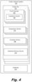
- Fig. 4 is a block diagram of a fluid analysis system (100) for determining fluidic properties from fluid impedance, according to another example of the principles described herein.
- the fluid analysis system includes a plurality of fluidic die (102).
- Each fluidic die (102) having multiple fluid chambers (104) and corresponding impedance sensors (106).
- impedance sensors (106) With multiple impedance sensors (106) a gradient of the property across the fluidic die (102) can be determined. For example, temperatures, or particulate concentration within a fluid, can be indicated as a gradient across the length of the fluidic die (102).
- the fluidic analysis system (100) may have multiple evaluator devices (108) which may or may not be on the fluidic die (102). Note that the number of each of these components may be different or the same.
- each fluid chamber (104) may have its own evaluator device (108) such that the number of fluid chambers (104) and evaluator devices (108) is the same.
- the number of evaluator devices (108) is less than the number of fluid chambers (104) such that multiple impedance sensors (106) output measurements of impedance to a shared evaluator device (108).
- the fluidic analysis system (100) includes at least one electrical stimulus source (210).
- Fig. 4 depicts the electrical stimulus source (210) being disposed on the fluidic die (402), however in some examples it may be off the fluidic die (402).
- multiple evaluator devices (108) may be coupled to the electrical stimulus source (210). That is, a shared electrical stimulus source (210) may pass electrical stimuli to multiple impedance sensors (106).
- the fluid analysis system (100) includes a network of switches through which electrical stimuli can be passed to desired impedance sensors (106). The network of switches would also regulate to which evaluator devices (108) impedance sensor measurements and data describing the electrical stimulus are passed.
- the fluid analysis system also includes a temperature sensor (412) to measure a temperature of the substrate of the fluidic die (102).
- the temperature sensor(s) (412) may be disposed on, or embedded in, the fluidic die (102).
- a temperature sensor (412) may take various forms.
- a temperature sensor (412) may be a thermal sense resistor (TSR) that spans the length of the fluidic die (102) and takes an aggregate temperature of the substrate.
- TSR thermal sense resistor
- the number of temperature sensors (412) is less than the number of fluid chambers (104).
- the number of temperature sensors (412) may be the same as the number of fluid chambers (104).
- a diode thermal sensor may be placed near, or in, the fluid chamber (104).
- each fluid chamber (104) may have a unique diode temperature sensor (412).
- multiple fluid chambers (104) may be paired with a single diode temperature sensor (412).
- the temperature sensor (412) measures the temperature of the substrate and/or fluid, and the raw impedance measurements from the impedance sensor (106) and the temperature measured by the temperature sensor (412) can be used to more accurately identify characteristics or properties of the fluid.
- the fluid analysis system (100) includes a database (414).
- the database (414) includes a mapping between real and imaginary components of impedance and the at least one property.
- the mapping may be between distinct components, i.e., real and imaginary, of the impedance and the at least one property. That is, once an impedance sensor (106) measures a particular impedance component, be it real or imaginary, output values related to these measurements are identified in the database (414), which database (414) correlates the output to a known property of the fluid.
- the database (414) may map different values of real components of impedance and/or different values of imaginary components of impedance and initial electrical stimuli with different propert(ies) of fluid(s), or to different values of the different properties. Accordingly, with a known initial electrical stimulus and known impedance responses for that electrical stimulus, the evaluator device (108) can determine the properties of that particular fluid.
- Fig. 5 is a diagram of a fluid analysis system (100) for determining fluidic properties from fluid impedance, according to another example of the principles described herein.
- the fluid analysis system (100) includes a fluid chamber (104) in which fluid to be analyzed is disposed. Inside the fluid chamber (104) is an impedance sensor (106) which determines an impedance of the fluid disposed therein.
- the electrical stimulus source (210) forces an electrical stimulus, be it a current or voltage, onto the impedance sensor (106).
- an output of the impedance sensor (106) is passed to a sample and hold circuit (516) that captures an output, be it a voltage or current and holds its value at a constant level for a specified period of time.
- This sampled output is then passed to an A/D converter (518) that converts the analog output into a signal usable by the evaluator device (108).
- the A/D converter converts the analog value into a digital word.
- the evaluator device (108) uses this digital word, along with data (523) describing the electrical stimulus, to identify, from a database ( Fig. 4 , 414) various properties for the fluid.
- An output (522) of the evaluator device (108) is indicative of the property, which output can be used to carry out any number of operations within the application in which the fluid analysis system (100) is used.
- the electrical stimulus source (210) may be controlled by a source control signal (520).
- the source control signal activates the electrical stimulus source (210) to pass the electrical stimuli to the impedance sensor (106) and the evaluator device (108).
- data (523) describing the electrical stimulus is provided to the evaluator device (108) such that a determination of a property can be made.
- the fluid analysis system (100) senses the shape of the output voltage (or current) curve that results from an electrical stimulus (of current, or voltage, respectively) applied to the impedance sensor (106).
- the shape of the output voltage or current can be sensed (in part) by taking a measurement at a specific time as the voltage/current is rising.
- the fluid analysis system (100) may be used to determine a health of an ink.
- good fluid may have a signal of 2.5v at 1uS after a 1mA pulse is applied, at 60 degrees C and 2.8v at 70 degrees C. Additional data points may be used as well. With this data, the fluid analysis system (100) can discern "good” ink from "bad” ink. In other words, not only does the fluid analysis system (100) determine a real and complex impedance, but also determines a transient response to an electrical stimulus by taking impedance measures after a predetermined period of time.
- Fig. 6 is a side view of an impedance sensor (106) of a fluid analysis system ( Fig. 1 , 100) for determining fluidic properties from fluid impedance, according to another example of the principles described herein.
- the impedance sensor (106) is disposed within a fluid chamber (104). While Fig. 6 depicts the impedance sensor (106) on a bottom surface of the fluid chamber (104), the impedance sensor (106) may take other shapes, such as a pillar and may be on other surfaces, such as a sidewall of the fluid chamber (104).
- the impedance sensor (106) may be disposed on a passivation layer (628), which passivation layer (628) is disposed on an actuator (626) which is disposed on a substrate (624) of the fluidic die ( Fig. 1 , 102).
- the substrate (624) refers to a surface in which various components of the fluidic die (624) are formed.
- the substrate (624) may include various layers including a silicon layer in which fluid chambers (104) are disposed.
- the impedance sensor (106) may include a single electrically conductive layer, formed of a material such as tantalum or aluminum, which can detect an impedance of whatever medium is within the fluid chamber (104). Specifically, each impedance sensor (106) measures an impedance of the medium within the fluid chamber (104), which impedance measurement, as described above, can be used, either alone or in conjunction with a temperature sensor ( Fig. 4 , 412) to determine properties of the fluid within the fluid chamber (104).
- using such a fluidic die 1) allows for fluidic property detection at a micro-fluidic level; 2) provides for simple property determination based on imaginary and/or real components of a sensed impedance; 3) is cost effective as sensor materials are simple and easy to work with.
Landscapes
- Chemical & Material Sciences (AREA)
- Health & Medical Sciences (AREA)
- General Physics & Mathematics (AREA)
- General Health & Medical Sciences (AREA)
- Analytical Chemistry (AREA)
- Physics & Mathematics (AREA)
- Immunology (AREA)
- Life Sciences & Earth Sciences (AREA)
- Biochemistry (AREA)
- Chemical Kinetics & Catalysis (AREA)
- Pathology (AREA)
- Electrochemistry (AREA)
- Engineering & Computer Science (AREA)
- Power Engineering (AREA)
- Dispersion Chemistry (AREA)
- Quality & Reliability (AREA)
- Hematology (AREA)
- Clinical Laboratory Science (AREA)
- Investigating Or Analyzing Materials By The Use Of Electric Means (AREA)
Claims (11)
- Flüssigkeitsanalysesystem (100), das umfasst:
eine fluidische Düse (104), wobei die fluidische Düse (104) umfasst:die Flüssigkeitskammer (104), die dazu konfiguriert ist, ein zu analysierendes Flüssigkeitsvolumen zu halten; undeinen Impedanzsensor (106), der innerhalb der Flüssigkeitskammer (104) angebracht ist;eine Quelle (210) eines elektrischen Stimulus, die dazu konfiguriert ist, einen elektrischen Stimulus an den Impedanzsensor in der Flüssigkeitskammer an der fluidische Düse zu liefern, wobei die Quelle (210) des elektrischen Stimulus dazu konfiguriert ist, einen ersten elektrischen Stimulus zum Messen einer realen Komponente einer Impedanz und einen zweiten elektrischen Stimulus zum Messen einer imaginären Komponente einer Impedanz zu liefern;wobei der Impedanzsensor (106) dazu konfiguriert ist, eine Impedanz der Flüssigkeit in der Flüssigkeitskammer (104) auf der Basis von dem ersten und dem zweiten elektrischen Stimulus zu messen;eine Abtast-Halte-Schaltung (516), die dazu konfiguriert ist, eine Ausgabe von dem Impedanzsensor (106) zu erfassen und ihren Wert für eine festgelegte Zeitperiode auf einem konstanten Pegel zu halten;wobei die Stimulusquelle (210) dazu konfiguriert ist, den ersten elektrischen Stimulus zum Aufladen einer Kapazität des Impedanzsensors und zum Erreichen eines stationären Zustands der Ausgabe von dem Impedanzsensor zu liefern; und wobei die Abtast-Halte-Schaltung dazu konfiguriert ist, die Ausgabe abzutasten, während die Stimulusquelle den ersten elektrischen Stimulus anlegt;wobei die Stimulusquelle (210) dazu konfiguriert ist, den zweiten elektrischen Stimulus für eine zuvor bestimmten Periode zu liefern, und wobei die Abtast-Halte-Schaltung dazu konfiguriert ist, die Ausgabe an dem Ende des zuvor bestimmten Zeitperiode abzutasten;einen A/D-Wandler (518), der dazu konfiguriert ist, die abgetastete Ausgabe von der Abtast-Halte-Schaltung (516) in eine digitale Ausgabe umzuwandeln; undeine Auswertervorrichtung (108), die konfiguriert ist zum:Bestimmen der realen Komponente der Impedanz, wenn der erste elektrische Stimulus angelegt wird, sodass die Kapazität des Impedanzsensors (106) aufgeladen ist und die Ausgabe des Impedanzsensors (106) einen stationären Zustand erreicht hat;Bestimmen der imaginären Komponente der Impedanz aus der Ausgabe des Impedanzsensors (106), die an dem Ende der zuvor bestimmten Zeitperiode einer Lieferung des zweiten Stimulus abgetastet wird; undBestimmen, aus einer Datenbank (414), mindestens einer Eigenschaft der Flüssigkeit auf der Basis von der digitalen Ausgabe des A/D-Wandlers (518), die die reale Komponente der Impedanz und die imaginäre Komponente der Impedanz umfasst, und von Daten (523), die den elektrischen Stimulus beschreiben. - Flüssigkeitsanalysesystem (100) nach Anspruch 1, wobei:die Quelle (210) des elektrischen Stimulus eine Stromquelle ist, die dazu konfiguriert ist, auf der Basis von einer zu bestimmenden Komponente dem Impedanzsensor (106) unterschiedliche Ströme aufzuzwingen; undeine Ausgabe des Impedanzsensors (106) eine Spannung ist, die auf der zu bestimmenden Komponente und einem erzwungenen Strom basiert.
- Flüssigkeitsanalysesystem (100) nach Anspruch 1, wobei:die Quelle (210) des elektrischen Stimulus eine Spannungsquelle ist, die dazu konfiguriert ist, auf der Basis von einer zu bestimmenden Komponente unterschiedliche Spannungen an den Impedanzsensor (106) anzulegen; undeine Ausgabe des Impedanzsensors (106) ein Strom ist, der auf der zu bestimmenden Komponente und einer angelegten Spannung basiert.
- Flüssigkeitsanalysesystem (100) nach Anspruch 1, wobei die Datenbank (414) eine Abbildung zwischen realen und imaginären Komponenten einer Impedanz und der mindestens einen Flüssigkeitseigenschaft umfasst.
- Flüssigkeitsanalysesystem (100) nach Anspruch 1, wobei die Auswertervorrichtung (108) an der fluidischen Düse (104) angeordnet ist.
- Flüssigkeitsanalysesystem nach Anspruch 1, wobei die Auswertervorrichtung (108) außerhalb der fluidischen Düse (104) angeordnet ist.
- Flüssigkeitsanalysesystem (100) nach Anspruch 1, wobei der Impedanzsensor (106) eine leitfähige Metallschicht umfasst, die auf einer Passivierungsschicht angeordnet ist.
- Flüssigkeitsanalysesystem (100) nach Anspruch 7, wobei die leitfähige Metallschicht aus mindestens einem von Tantal und Aluminium ausgebildet ist.
- Flüssigkeitsanalysesystem (100) nach Anspruch 1, wobei:die fluidische Düse (102) ferner einen Temperatursensor (412) umfasst, der dazu konfiguriert ist, eine Temperatur eines Substrats der fluidischen Düse (102) zu messen; unddie Auswertervorrichtung (108) dazu konfiguriert ist, die mindestens eine Eigenschaft der Flüssigkeit ferner auf der Basis von der gemessenen Temperatur des Substrats zu bestimmen.
- Flüssigkeitsanalysesystem (100) nach Anspruch 9, wobei die mindestens eine Eigenschaft eine Eigenschaft umfasst, die aus der Gruppe ausgewählt ist, bestehend aus den Folgenden:einer Flüssigkeitstemperatur;Partikelzusammensetzung der Flüssigkeit;Flüssigkeitszusammensetzung;Konzentration einer Komponente der Flüssigkeit; undFlüssigkeitsviskosität.
- Verfahren (300), das umfasst:Weitergeben (301) eines ersten elektrischen Stimulus und eines zweiten elektrischen Stimulus an einen Impedanzsensor in einer Flüssigkeitskammer an einer fluidischen Düse, wobei der erste elektrische Stimulus dazu dient, eine reale Komponente einer Impedanz zu messen, und der zweite elektrische Stimulus dazu dient, eine imaginäre Komponente einer Impedanz zu messen;Weitergeben (302) von Daten, die den ersten und den zweiten elektrischen Stimulus beschreiben, an eine Auswertervorrichtung;Messen (303), mit einem Impedanzsensor, einer Impedanz einer Flüssigkeit in der Flüssigkeitskammer auf der Basis von dem ersten und dem zweiten elektrischen Stimulus;Bestimmen einer realen Komponente der Impedanz;Bestimmen einer imaginären Komponente der Impedanz; undBestimmen (304) mindestens einer Eigenschaft der Flüssigkeit auf der Basis von 1) der realen Komponente der Impedanz und der imaginären Komponente der Impedanz und 2) den Daten, die den mindestens einen elektrischen Stimulus beschreiben, wobei, wenn die reale Komponente der Impedanz bestimmt wird:der erste elektrische Stimulus angelegt wird, sodass eine Kapazität des Impedanzsensors aufgeladen ist und eine Ausgabe des Impedanzsensors einen stationären Zustand erreicht hat; unddas Verfahren ferner ein Abtasten der Ausgabe, während der erste elektrische Stimulus angelegt wird, und ein Umwandeln der abgetasteten Ausgabe in eine digitale Ausgabe umfasst; undwenn die imaginäre Komponente der Impedanz bestimmt wird:der zweite elektrische Stimulus für eine zuvor bestimmte Zeitperiode angelegt wird; unddas Verfahren ferner ein Abtasten der Ausgabe an dem Ende der zuvor bestimmten Zeitperiode und ein Umwandeln der abgetasteten Ausgabe in eine digitale Ausgabe umfasst.
Applications Claiming Priority (1)
| Application Number | Priority Date | Filing Date | Title |
|---|---|---|---|
| PCT/US2018/014950 WO2019147225A1 (en) | 2018-01-24 | 2018-01-24 | Fluidic property determination from fluid impedances |
Publications (3)
| Publication Number | Publication Date |
|---|---|
| EP3704475A1 EP3704475A1 (de) | 2020-09-09 |
| EP3704475A4 EP3704475A4 (de) | 2020-11-25 |
| EP3704475B1 true EP3704475B1 (de) | 2025-03-12 |
Family
ID=67394802
Family Applications (1)
| Application Number | Title | Priority Date | Filing Date |
|---|---|---|---|
| EP18902063.9A Active EP3704475B1 (de) | 2018-01-24 | 2018-01-24 | Bestimmung der fluidischen eigenschaften von flüssigkeitsimpedanzen |
Country Status (4)
| Country | Link |
|---|---|
| US (1) | US11467116B2 (de) |
| EP (1) | EP3704475B1 (de) |
| CN (1) | CN111615628A (de) |
| WO (1) | WO2019147225A1 (de) |
Families Citing this family (3)
| Publication number | Priority date | Publication date | Assignee | Title |
|---|---|---|---|---|
| US20250020607A1 (en) * | 2023-07-13 | 2025-01-16 | Analog Devices International Unlimited Company | Property detection for fluid in cartridge |
| JP2025184321A (ja) * | 2024-06-07 | 2025-12-18 | 本田技研工業株式会社 | インクの評価方法 |
| JP2025184322A (ja) * | 2024-06-07 | 2025-12-18 | 本田技研工業株式会社 | インクの評価方法 |
Citations (2)
| Publication number | Priority date | Publication date | Assignee | Title |
|---|---|---|---|---|
| GB2288022A (en) * | 1994-03-23 | 1995-10-04 | Central Research Lab Ltd | Method of sensing the condition of a piece of food |
| US20170028738A1 (en) * | 2014-01-30 | 2017-02-02 | Hewlett-Packard Development Company, L.P. | Printheads with sensor plate impedance measurement |
Family Cites Families (20)
| Publication number | Priority date | Publication date | Assignee | Title |
|---|---|---|---|---|
| DE3228542A1 (de) * | 1982-07-30 | 1984-02-02 | Siemens AG, 1000 Berlin und 8000 München | Verfahren zur bestimmung der konzentration elektrochemisch umsetzbarer stoffe |
| US6204656B1 (en) | 1997-05-29 | 2001-03-20 | Reid Asset Management Company | Miniature sensor for lubricant analysis |
| DE10032207C2 (de) * | 2000-07-03 | 2002-10-31 | Univ Karlsruhe | Verfahren, Vorrichtung und Computerprogrammprodukt zur Bestimmung zumindest einer Eigenschaft einer Testemulsion und/oder Testsuspension sowie Verwendung der Vorrichtung |
| US10018613B2 (en) * | 2006-11-16 | 2018-07-10 | General Electric Company | Sensing system and method for analyzing a fluid at an industrial site |
| US9261474B2 (en) * | 2012-12-28 | 2016-02-16 | General Electric Company | Methods for analysis of fluids |
| EP2420826A1 (de) * | 2010-08-17 | 2012-02-22 | Nxp B.V. | Integrierte Schaltung und Verfahren zu deren Herstellung |
| US20130293246A1 (en) | 2010-11-17 | 2013-11-07 | Advanced Liquid Logic Inc. | Capacitance Detection in a Droplet Actuator |
| US9829451B2 (en) | 2011-10-09 | 2017-11-28 | Simon Fraser University | Microfluidic reconfiguration device for multi-plexed sample analysis |
| KR101949830B1 (ko) | 2011-10-24 | 2019-02-19 | 휴렛-팩커드 디벨롭먼트 컴퍼니, 엘.피. | 유체 방출 장치 및 유체 방출 방법 |
| US9408567B2 (en) | 2012-06-08 | 2016-08-09 | Medtronic Minimed, Inc. | Application of electrochemical impedance spectroscopy in sensor systems, devices, and related methods |
| CN105143859B (zh) * | 2013-03-14 | 2018-12-04 | 惠普发展公司,有限责任合伙企业 | 检测物质的设备和制造这样的设备的方法 |
| CN105283760B (zh) * | 2013-04-30 | 2020-08-14 | 惠普发展公司,有限责任合伙企业 | 微流体感测装置和系统 |
| WO2014198428A1 (en) * | 2013-06-10 | 2014-12-18 | Roche Diagnostics Gmbh | Method and system for detecting an analyte in a body fluid |
| KR101872380B1 (ko) * | 2014-01-30 | 2018-06-28 | 휴렛-팩커드 디벨롭먼트 컴퍼니, 엘.피. | 미세유체 감지 장치 |
| WO2015189274A1 (en) * | 2014-06-10 | 2015-12-17 | Qloudlab Sa | Set of modules, measurement device, system and method for the analysis of a fluid sample |
| US20170248572A1 (en) | 2014-09-26 | 2017-08-31 | Sikorsky Aircraft Corporation | Lubricant condition assessment system |
| CA2964310C (en) * | 2014-10-14 | 2019-02-26 | Becton, Dickinson And Company | Reactance and capacitance sensing platform for detecting microorganisms |
| FR3027669B1 (fr) | 2014-10-22 | 2018-05-25 | Dover Europe Sarl | Dispositif de mesure de niveau dans un reservoir |
| JP6397395B2 (ja) * | 2014-12-30 | 2018-09-26 | ゼネラル・エレクトリック・カンパニイ | 検出方法およびシステム |
| EP3316811B1 (de) | 2015-06-30 | 2019-08-21 | Smith & Nephew, Inc. | Temperaturmessung von elektrisch leitfähigen flüssigkeiten |
-
2018
- 2018-01-24 EP EP18902063.9A patent/EP3704475B1/de active Active
- 2018-01-24 US US16/766,633 patent/US11467116B2/en active Active
- 2018-01-24 WO PCT/US2018/014950 patent/WO2019147225A1/en not_active Ceased
- 2018-01-24 CN CN201880087692.4A patent/CN111615628A/zh active Pending
Patent Citations (2)
| Publication number | Priority date | Publication date | Assignee | Title |
|---|---|---|---|---|
| GB2288022A (en) * | 1994-03-23 | 1995-10-04 | Central Research Lab Ltd | Method of sensing the condition of a piece of food |
| US20170028738A1 (en) * | 2014-01-30 | 2017-02-02 | Hewlett-Packard Development Company, L.P. | Printheads with sensor plate impedance measurement |
Also Published As
| Publication number | Publication date |
|---|---|
| EP3704475A4 (de) | 2020-11-25 |
| EP3704475A1 (de) | 2020-09-09 |
| CN111615628A (zh) | 2020-09-01 |
| US20210010967A1 (en) | 2021-01-14 |
| WO2019147225A1 (en) | 2019-08-01 |
| US11467116B2 (en) | 2022-10-11 |
Similar Documents
| Publication | Publication Date | Title |
|---|---|---|
| EP3704475B1 (de) | Bestimmung der fluidischen eigenschaften von flüssigkeitsimpedanzen | |
| US7413710B2 (en) | Pipette system and pipette array | |
| US20190240985A1 (en) | Fluid reservoir with fluid property and level detection | |
| EP3427040B1 (de) | Mikrofluidische vorrichtungen | |
| WO2019133424A1 (en) | Pipette tip for and method of automatically maintaining pipette tip depth in a fluid | |
| US20230391075A1 (en) | Pipette-fillable cartridge fluid detection | |
| EP3427035B1 (de) | Mikrofluidische vorrichtungen | |
| EP3436799B1 (de) | Mikrofluidische vorrichtungen zur fluidbewegungssteuerung | |
| TW201732256A (zh) | 以序列流體驅動器致動之微流體感測技術 | |
| Ahamed et al. | A piezoactuated droplet-dispensing microfluidic chip | |
| US11896971B2 (en) | Fluid detection circuit for fluid ejection head | |
| Steger et al. | Two-dimensional array of piezostack actuated nanoliter dispensers | |
| US11117134B2 (en) | Non-poissonian droplet partitioning using feedback | |
| WO2019055030A1 (en) | DISTRIBUTION OF DNA CONCENTRATE | |
| US20240131504A1 (en) | Fluid detection circuit for fluid ejection head | |
| Ernst et al. | Noncontact determination of velocity and volume of nanoliter droplets on the fly | |
| Zargar et al. | Design and development of a non-contact cross-capacitive micro droplet detector | |
| LU501474B1 (en) | Method for determining a volume of liquid arranged in a receptacle | |
| LU501476B1 (en) | Method for determining a function for determining a volume of liquid to be dispensed | |
| US20200298226A1 (en) | Fluid ejection dies with fluid cleaning structures | |
| CN114729950A (zh) | 阵列液滴操纵 | |
| LU501475B1 (en) | Method for determining a function for determining a volume of liquid to be dispensed | |
| US20250033042A1 (en) | Microfluidic devices with dielectrophoretic actuators | |
| Izadian et al. | Pico-droplet dispensing control in digital microfluidic systems |
Legal Events
| Date | Code | Title | Description |
|---|---|---|---|
| STAA | Information on the status of an ep patent application or granted ep patent |
Free format text: STATUS: THE INTERNATIONAL PUBLICATION HAS BEEN MADE |
|
| PUAI | Public reference made under article 153(3) epc to a published international application that has entered the european phase |
Free format text: ORIGINAL CODE: 0009012 |
|
| STAA | Information on the status of an ep patent application or granted ep patent |
Free format text: STATUS: REQUEST FOR EXAMINATION WAS MADE |
|
| 17P | Request for examination filed |
Effective date: 20200531 |
|
| AK | Designated contracting states |
Kind code of ref document: A1 Designated state(s): AL AT BE BG CH CY CZ DE DK EE ES FI FR GB GR HR HU IE IS IT LI LT LU LV MC MK MT NL NO PL PT RO RS SE SI SK SM TR |
|
| AX | Request for extension of the european patent |
Extension state: BA ME |
|
| A4 | Supplementary search report drawn up and despatched |
Effective date: 20201022 |
|
| RIC1 | Information provided on ipc code assigned before grant |
Ipc: G01N 27/02 20060101AFI20201016BHEP Ipc: G01N 15/00 20060101ALI20201016BHEP Ipc: B41J 2/195 20060101ALI20201016BHEP Ipc: B01L 3/00 20060101ALI20201016BHEP |
|
| DAV | Request for validation of the european patent (deleted) | ||
| DAX | Request for extension of the european patent (deleted) | ||
| STAA | Information on the status of an ep patent application or granted ep patent |
Free format text: STATUS: EXAMINATION IS IN PROGRESS |
|
| 17Q | First examination report despatched |
Effective date: 20221110 |
|
| GRAP | Despatch of communication of intention to grant a patent |
Free format text: ORIGINAL CODE: EPIDOSNIGR1 |
|
| STAA | Information on the status of an ep patent application or granted ep patent |
Free format text: STATUS: GRANT OF PATENT IS INTENDED |
|
| INTG | Intention to grant announced |
Effective date: 20241125 |
|
| GRAS | Grant fee paid |
Free format text: ORIGINAL CODE: EPIDOSNIGR3 |
|
| GRAA | (expected) grant |
Free format text: ORIGINAL CODE: 0009210 |
|
| STAA | Information on the status of an ep patent application or granted ep patent |
Free format text: STATUS: THE PATENT HAS BEEN GRANTED |
|
| AK | Designated contracting states |
Kind code of ref document: B1 Designated state(s): AL AT BE BG CH CY CZ DE DK EE ES FI FR GB GR HR HU IE IS IT LI LT LU LV MC MK MT NL NO PL PT RO RS SE SI SK SM TR |
|
| REG | Reference to a national code |
Ref country code: GB Ref legal event code: FG4D |
|
| REG | Reference to a national code |
Ref country code: CH Ref legal event code: EP |
|
| REG | Reference to a national code |
Ref country code: DE Ref legal event code: R096 Ref document number: 602018080153 Country of ref document: DE |
|
| REG | Reference to a national code |
Ref country code: IE Ref legal event code: FG4D |
|
| PG25 | Lapsed in a contracting state [announced via postgrant information from national office to epo] |
Ref country code: RS Free format text: LAPSE BECAUSE OF FAILURE TO SUBMIT A TRANSLATION OF THE DESCRIPTION OR TO PAY THE FEE WITHIN THE PRESCRIBED TIME-LIMIT Effective date: 20250612 |
|
| PG25 | Lapsed in a contracting state [announced via postgrant information from national office to epo] |
Ref country code: FI Free format text: LAPSE BECAUSE OF FAILURE TO SUBMIT A TRANSLATION OF THE DESCRIPTION OR TO PAY THE FEE WITHIN THE PRESCRIBED TIME-LIMIT Effective date: 20250312 |
|
| PG25 | Lapsed in a contracting state [announced via postgrant information from national office to epo] |
Ref country code: ES Free format text: LAPSE BECAUSE OF FAILURE TO SUBMIT A TRANSLATION OF THE DESCRIPTION OR TO PAY THE FEE WITHIN THE PRESCRIBED TIME-LIMIT Effective date: 20250312 |
|
| REG | Reference to a national code |
Ref country code: LT Ref legal event code: MG9D |
|
| PG25 | Lapsed in a contracting state [announced via postgrant information from national office to epo] |
Ref country code: NO Free format text: LAPSE BECAUSE OF FAILURE TO SUBMIT A TRANSLATION OF THE DESCRIPTION OR TO PAY THE FEE WITHIN THE PRESCRIBED TIME-LIMIT Effective date: 20250612 |
|
| PG25 | Lapsed in a contracting state [announced via postgrant information from national office to epo] |
Ref country code: HR Free format text: LAPSE BECAUSE OF FAILURE TO SUBMIT A TRANSLATION OF THE DESCRIPTION OR TO PAY THE FEE WITHIN THE PRESCRIBED TIME-LIMIT Effective date: 20250312 |
|
| REG | Reference to a national code |
Ref country code: NL Ref legal event code: MP Effective date: 20250312 |
|
| PG25 | Lapsed in a contracting state [announced via postgrant information from national office to epo] |
Ref country code: LV Free format text: LAPSE BECAUSE OF FAILURE TO SUBMIT A TRANSLATION OF THE DESCRIPTION OR TO PAY THE FEE WITHIN THE PRESCRIBED TIME-LIMIT Effective date: 20250312 |
|
| PG25 | Lapsed in a contracting state [announced via postgrant information from national office to epo] |
Ref country code: GR Free format text: LAPSE BECAUSE OF FAILURE TO SUBMIT A TRANSLATION OF THE DESCRIPTION OR TO PAY THE FEE WITHIN THE PRESCRIBED TIME-LIMIT Effective date: 20250613 Ref country code: BG Free format text: LAPSE BECAUSE OF FAILURE TO SUBMIT A TRANSLATION OF THE DESCRIPTION OR TO PAY THE FEE WITHIN THE PRESCRIBED TIME-LIMIT Effective date: 20250312 |
|
| REG | Reference to a national code |
Ref country code: AT Ref legal event code: MK05 Ref document number: 1775382 Country of ref document: AT Kind code of ref document: T Effective date: 20250312 |
|
| PG25 | Lapsed in a contracting state [announced via postgrant information from national office to epo] |
Ref country code: NL Free format text: LAPSE BECAUSE OF FAILURE TO SUBMIT A TRANSLATION OF THE DESCRIPTION OR TO PAY THE FEE WITHIN THE PRESCRIBED TIME-LIMIT Effective date: 20250312 |
|
| PG25 | Lapsed in a contracting state [announced via postgrant information from national office to epo] |
Ref country code: SE Free format text: LAPSE BECAUSE OF FAILURE TO SUBMIT A TRANSLATION OF THE DESCRIPTION OR TO PAY THE FEE WITHIN THE PRESCRIBED TIME-LIMIT Effective date: 20250312 |
|
| PG25 | Lapsed in a contracting state [announced via postgrant information from national office to epo] |
Ref country code: SM Free format text: LAPSE BECAUSE OF FAILURE TO SUBMIT A TRANSLATION OF THE DESCRIPTION OR TO PAY THE FEE WITHIN THE PRESCRIBED TIME-LIMIT Effective date: 20250312 |
|
| PG25 | Lapsed in a contracting state [announced via postgrant information from national office to epo] |
Ref country code: PT Free format text: LAPSE BECAUSE OF FAILURE TO SUBMIT A TRANSLATION OF THE DESCRIPTION OR TO PAY THE FEE WITHIN THE PRESCRIBED TIME-LIMIT Effective date: 20250714 |
|
| PG25 | Lapsed in a contracting state [announced via postgrant information from national office to epo] |
Ref country code: IT Free format text: LAPSE BECAUSE OF FAILURE TO SUBMIT A TRANSLATION OF THE DESCRIPTION OR TO PAY THE FEE WITHIN THE PRESCRIBED TIME-LIMIT Effective date: 20250312 Ref country code: PL Free format text: LAPSE BECAUSE OF FAILURE TO SUBMIT A TRANSLATION OF THE DESCRIPTION OR TO PAY THE FEE WITHIN THE PRESCRIBED TIME-LIMIT Effective date: 20250312 |
|
| PG25 | Lapsed in a contracting state [announced via postgrant information from national office to epo] |
Ref country code: AT Free format text: LAPSE BECAUSE OF FAILURE TO SUBMIT A TRANSLATION OF THE DESCRIPTION OR TO PAY THE FEE WITHIN THE PRESCRIBED TIME-LIMIT Effective date: 20250312 |
|
| PG25 | Lapsed in a contracting state [announced via postgrant information from national office to epo] |
Ref country code: CZ Free format text: LAPSE BECAUSE OF FAILURE TO SUBMIT A TRANSLATION OF THE DESCRIPTION OR TO PAY THE FEE WITHIN THE PRESCRIBED TIME-LIMIT Effective date: 20250312 Ref country code: EE Free format text: LAPSE BECAUSE OF FAILURE TO SUBMIT A TRANSLATION OF THE DESCRIPTION OR TO PAY THE FEE WITHIN THE PRESCRIBED TIME-LIMIT Effective date: 20250312 |
|
| PG25 | Lapsed in a contracting state [announced via postgrant information from national office to epo] |
Ref country code: RO Free format text: LAPSE BECAUSE OF FAILURE TO SUBMIT A TRANSLATION OF THE DESCRIPTION OR TO PAY THE FEE WITHIN THE PRESCRIBED TIME-LIMIT Effective date: 20250312 |
|
| PG25 | Lapsed in a contracting state [announced via postgrant information from national office to epo] |
Ref country code: SK Free format text: LAPSE BECAUSE OF FAILURE TO SUBMIT A TRANSLATION OF THE DESCRIPTION OR TO PAY THE FEE WITHIN THE PRESCRIBED TIME-LIMIT Effective date: 20250312 |
|
| PG25 | Lapsed in a contracting state [announced via postgrant information from national office to epo] |
Ref country code: IS Free format text: LAPSE BECAUSE OF FAILURE TO SUBMIT A TRANSLATION OF THE DESCRIPTION OR TO PAY THE FEE WITHIN THE PRESCRIBED TIME-LIMIT Effective date: 20250712 |
|
| REG | Reference to a national code |
Ref country code: DE Ref legal event code: R097 Ref document number: 602018080153 Country of ref document: DE |
|
| PG25 | Lapsed in a contracting state [announced via postgrant information from national office to epo] |
Ref country code: DK Free format text: LAPSE BECAUSE OF FAILURE TO SUBMIT A TRANSLATION OF THE DESCRIPTION OR TO PAY THE FEE WITHIN THE PRESCRIBED TIME-LIMIT Effective date: 20250312 |
|
| PLBE | No opposition filed within time limit |
Free format text: ORIGINAL CODE: 0009261 |
|
| STAA | Information on the status of an ep patent application or granted ep patent |
Free format text: STATUS: NO OPPOSITION FILED WITHIN TIME LIMIT |
|
| REG | Reference to a national code |
Ref country code: CH Ref legal event code: L10 Free format text: ST27 STATUS EVENT CODE: U-0-0-L10-L00 (AS PROVIDED BY THE NATIONAL OFFICE) Effective date: 20260121 |