EP3704352B1 - Einsetzbare vorrichtungen und verfahren - Google Patents
Einsetzbare vorrichtungen und verfahren Download PDFInfo
- Publication number
- EP3704352B1 EP3704352B1 EP18797078.5A EP18797078A EP3704352B1 EP 3704352 B1 EP3704352 B1 EP 3704352B1 EP 18797078 A EP18797078 A EP 18797078A EP 3704352 B1 EP3704352 B1 EP 3704352B1
- Authority
- EP
- European Patent Office
- Prior art keywords
- well structure
- mounting arrangement
- body portion
- wall surface
- conductive pads
- Prior art date
- Legal status (The legal status is an assumption and is not a legal conclusion. Google has not performed a legal analysis and makes no representation as to the accuracy of the status listed.)
- Active
Links
Images


Classifications
-
- E—FIXED CONSTRUCTIONS
- E21—EARTH OR ROCK DRILLING; MINING
- E21B—EARTH OR ROCK DRILLING; OBTAINING OIL, GAS, WATER, SOLUBLE OR MELTABLE MATERIALS OR A SLURRY OF MINERALS FROM WELLS
- E21B47/00—Survey of boreholes or wells
- E21B47/12—Means for transmitting measuring-signals or control signals from the well to the surface, or from the surface to the well, e.g. for logging while drilling
- E21B47/13—Means for transmitting measuring-signals or control signals from the well to the surface, or from the surface to the well, e.g. for logging while drilling by electromagnetic energy, e.g. radio frequency
-
- E—FIXED CONSTRUCTIONS
- E21—EARTH OR ROCK DRILLING; MINING
- E21B—EARTH OR ROCK DRILLING; OBTAINING OIL, GAS, WATER, SOLUBLE OR MELTABLE MATERIALS OR A SLURRY OF MINERALS FROM WELLS
- E21B17/00—Drilling rods or pipes; Flexible drill strings; Kellies; Drill collars; Sucker rods; Cables; Casings; Tubings
- E21B17/10—Wear protectors; Centralising devices, e.g. stabilisers
- E21B17/1014—Flexible or expansible centering means, e.g. with pistons pressing against the wall of the well
- E21B17/1021—Flexible or expansible centering means, e.g. with pistons pressing against the wall of the well with articulated arms or arcuate springs
Definitions
- Described examples relate to deployable devices, such as deployable contact devices, including those that may be used for signalling contact, and methods of use within a well.
- Signalling within a well can be used to communicate data and/or power from one location at the well to another, for example communicate data and/or power from surface to a location downhole.
- One method of communicating power and/or data signals downhole comprises using the metallic well structure itself as part of the signal path.
- the metallic tubing within the well may be used not only for structural reasons, but may also serve as a communication path for signals, such as electrical signals (e.g. EM signals).
- Communicating in this manner presents a number of technical challenges, such as managing signal attenuation or noise ratios.
- U.S. Patent Application Publication No. 2015/0267530 A1 is directed to a well installation communication system which includes downhole metallic structure, a downhole communication unit and a surface communication unit arranged for electrical signal communication with the downhole communication unit via a signal channel.
- the signal channel includes a portion of the downhole metallic structure, a portion of cable running within the downhole metallic structure away from the portion of the downhole metallic structure toward the surface, and a connection device which is in the signal channel between the portion of metallic structure and the portion of cable.
- PCT Application Publication No. WO 2016/137462 A1 is directed to a downhole sensor deployment assembly which includes a body attachable to a completion string and one or more arms pivotably coupled to the body.
- a sensor pad is coupled to each arm and movable from a retracted position, wherein the sensor pad is stowed adjacent the completion string, and an actuated position, where the sensor pad is extend radially away from the completion string.
- a versatile high-expansion hanger device for suspension of downhole devices during performance of critical asset diagnostics and enhancement methods authored by Zbitowski et al. at SPE 25-26 March 2014 describes a high-expansion hanger.
- US Patent Application Publication No. US 2008/0007422 A1 which is considered to be the closest prior art, describes a downhole signal receiving system where a pair of setting devices are used to electrically connect with downhole structure and are connected to one another by a bulk conductor.
- Such signalling may include the communication of power and/or data signals.
- the devices and methods used may assist with efficient and/or effective communication of such signals.
- a deployable electrical contact device is provided according to claim 1.
- a method for communicating electrical signals in a well is provided according to claim 18.
- Such devices may comprise a body portion.
- the device, and indeed the body portion may be configured for deployment in a well bore, e.g. the body portion may be considered to be an elongated body portion.
- Such devices may comprise a mounting arrangement, which may be configured to retain the device at a location at a well structure (e.g. retained at a desired location).
- the mounting arrangement may be configured to engage mechanically with a wall surface of that well structure.
- the wall surface may be in inner bore wall of the well structure.
- the mounting arrangement may be controllably deployable from the body portion.
- the device may be configured such that the mounting arrangement is deployable upon a controlled activation.
- the mounting arrangement may comprise conductive pads to provide signalling continuity between engaged well structure and the mounting arrangement.
- the pads may be electrically conductive pads to provide electrical continuity for signalling purposes.
- the pads may be acoustically conductive pads to provide acoustic continuity for signalling purposes (e.g. the pads may be configured to be impedance matched with an expected well structure, or the like).
- the device may be configured such that there is provided a signal path between one or more of the conductive pads and the body portion so as to provide signalling continuity between well structure and body portion, when deployed.
- the body portion may comprise one or more connection points electrically connecting the device to further apparatus for further signalling therefrom.
- the signal path may be provided between the conductive pads and the connection point(s) so as to allow for signalling continuity between well structure and further apparatus (e.g. further tools, devices, e-lines, etc. connected to the device at the connection point).
- the device may comprise a plurality of connection points. Each connection point may be provided at a common potential. Some or all connection points may be selectable (e.g. by the device) in order to direct signals to one or more apparatus attached at particular connections points.
- the device may be configured, during deployment, to abrade a wall surface of a well structure.
- the device may be configured to specifically scrub a wall of the well structure during deployment.
- the device may be configured to liberate or displace built-up coatings or detritus at the wall of the well structure. Doing so may provide signalling continuity, such as improved electrical continuity, between that engaged well structure and the mounting arrangement (e.g. compared to merely making mechanical contact with a wall of well structure).
- the conductive pads may comprise a contact surface, which may be configured to engage and abrade a wall surface, when deployed.
- the contact surface may comprise a plurality of serrations or the like, configured to engage with and abrade a wall surface.
- the mounting arrangement may comprise deployment arms (e.g. a plurality of deployment arms).
- the deployment arms may be regularly spaced around the device (e.g. at 30, 45, 60, 90, 120, or 180 degree intervals).
- the deployment arms may have a stowed configuration (e.g. for running into the well, and possibly retrieving from the well).
- the deployment arms In a deployed configuration, the deployment arms may extend from the body portion so as to urge the conductive pads into contact with a well structure.
- the deployment arms may be rotatably attached to the conductive pads at a linkage region.
- some or all of the deployment arms may comprise a contact surface for contact with a wall surface.
- the contact surface may be specifically configured for contact with a wall surface of a well structure, when deployed. In some cases, the contact surface may be provided at the linkage region.
- the contact surface of the deployment arms may comprise a plurality of serrations, or the like, configured to engage with and abrade a wall surface.
- the device may be configured such that, rotation of the arms relative to the conductive pads, causes counteraction of the contact surfaces of the conductive pads and of the deployment arms at a wall surface of a well structure. Such counteraction of contact surfaces may assist with abrading that wall surface in use.
- the deployment arms may comprise a connection element, e.g. to provide a signalling connection to the body portion.
- the connection element may be configured to orbit and maintain signalling connection with a socket arrangement of the body portion. In such a way, when the arms are controllably moved between the stowed and deployed configuration, the connection element may maintain signalling continuity with the body portion, and so maintain the signal path from the deployment arms and the body portion.
- the device may be configured such that the signal path can be provided from the mounting arrangement to the body portion via the socket arrangement.
- the deployment arms may be rotatably connected to the body portion via a compliant connection.
- the compliant connection may assist with maintaining signalling continuity between the deployment arms and the body portion.
- the mounting arrangement may be controllably deployable from the body portion using a drive unit.
- a drive unit may be operable to deploy and subsequently retract the mounting arrangement, in use.
- the drive unit may be configured to be operable to deploy and subsequently retract the mounting arrangement, and then further deploy the mounting arrangement.
- Such re-deployment may assist with repositioning the device in a well, and/or may assist with abrading a wall surface of a well structure, e.g. at a particular location.
- the drive unit may comprise a lead screw arrangement configured to deploy and retract the mounting arrangement.
- the drive unit may be packaged within the body portion of the device. While of course the drive unit may be powered by a number of different means (e.g. hydraulically), in some cases the device may comprise a battery unit for powering the drive unit. Such a battery unit may be being configured to be chargeable from signals (e.g. electrical signals) being communicated using the signal path.
- the drive unit may be configured to deploy and/or retract the mounting arrangement using a pressure system.
- the pressure system may act against a piston, or the like, in order to move the mounting arrangement to the deployed/retracted configuration.
- the pressure system may utilise well pressure to actuate the mounting arrangement (e.g. using a controllable valve, burst disc, etc. to permit well fluids to act upon a piston arrangement).
- the pressure system may comprise a pressure reservoir configured to act upon a piston arrangement, or the like, when controlled to do so.
- the device may be configured, in use, to couple with further apparatus so as to communicate signals to and/or from that further apparatus and well structure.
- the device may be configured to communicate data and/or power electrical signals to/from well structure.
- a deployable string e.g. a tool string
- the string may comprise a contact device, as described above.
- the string may comprise two or more such contact devices.
- the contact devices may be axially displaced from one another along the string.
- Such a deployable string may comprise one or more downhole gauges, casing collar locators, survey tools or other downhole tools.
- two or more of the contact devices may be independently operable in order to deploy and retain the string at a position in a well structure.
- each of the contact devices may be operable separately. This may permit controlled deployment of one device, and then the other device.
- the string may be configured for controlled sequential deployment of the devices.
- the method may comprise deploying a contact device to a location in well.
- the method may comprise controllably deploying a mounting arrangement of the device so as to mechanically, and in some examples electrically, engage with a wall surface of that well structure.
- the method may further comprise communicating electrical and/or acoustic signals to/from the well structure using a signal path formed between the device and the well structure, e.g. using the mounting arrangement.
- the method may comprise abrading the wall surface of a well structure so as to provide signalling continuity, or indeed improve continuity, between that engaged well structure and the mounting arrangement.
- the method may comprise assessing the continuity between the device and the well structure.
- the continuity between the device and the well structure may be assessed by measuring the impedance along the signal path, e.g. at the device/well structure.
- the method may comprise controllably retracting and re-deploying the mounting arrangement in the event of an observed lack of continuity or an observed impedance beyond a threshold (e.g. an impedance variation beyond a predefined threshold).
- the method may comprise re-deploying the signalling contact device to a different location in the well, prior to re-deploying the mounting arrangement.
- the method may comprise deploying two or more contact devices as part of a deployable string.
- the method may comprise controllably deploying mounting arrangements of each of the devices so as to mechanically, and in some examples electrically, engage with a wall surface of that well structure.
- the method may comprise controllably retracting and re-deploying each mounting arrangements independently (or otherwise separately) in the event of an observed lack of continuity or an observed impedance beyond a threshold (e.g. an impedance indicting lack or poor electrical continuity, or otherwise an acoustic impedance mismatch beyond a threshold).
- a method of charging a battery unit downhole such as a battery unit of a wellbore device (e.g. a movable device in a well bore).
- the device may be configured so as to be movable from a first location to second location within a well.
- the method may comprise controllably deploying a mounting arrangement of the device so as to mechanically and electrically engage with a wall surface of a metallic well structure; and communicating electrical signals from the well structure to a battery unit of the device using an electrical signal path formed between the device and the metallic well structure, e.g. via the mounting arrangement.
- the method may include charging a battery unit of a further device positioned in the well.
- electrical signals may be communicated from the well structure to a battery unit using an electrical signal path formed between the movable device and the metallic well structure, via the mounting arrangement, whereby the battery unit is in electrical communication with the movable device (e.g. the battery unit may be provided in a gauge or sensor unit, which may be electrically connected to the moveable device).
- a computer program product or computer file configured to at least partially (or fully) implement the device and methods as described above.
- a carrier medium comprising or encoding the computer program product or computer file.
- the program or file may be non-transitory.
- processing apparatus when programmed with the computer program product described.
- the invention includes one or more corresponding aspects, embodiments or features in isolation or in various combinations whether or not specifically stated (including claimed) in that combination or in isolation.
- features associated with particular recited embodiments relating to devices may be equally appropriate as features of embodiments relating specifically to methods of operation or use, and vice versa.
- one or more embodiments/aspects may assist with efficient and/or effective communication of signals in a well.
- signalling can include the communication of data and/or power signals.
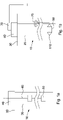
- FIG 1a shows a simplified representation of a section of a well 10, and in this case a production well 10.
- metallic well structure 20 extends from the surface 30 to a subterranean formation, as will be appreciated.
- the well 10 may be an appraisal well, injection well, or the like.
- the well 10 may be used for the production/injection of other fluids other than those in the oil and gas industry (e.g. water production).
- such well structure 20 may include conductor, casing and other tubing used to recover product from the formation.
- the well 10 comprises a wellhead 40, whether that may include a wet tree, dry tree or the like, at the surface 30.
- the wellhead/tree arrangement 40 may be provided at a production platform, for example having conductor extending to the seabed, as will be appreciated.
- a device 50 - and in this example a deployable electrical contact device 50 - is being deployed in the well 10.
- the device 50 is being deployed using an elongated deployable medium 60, such as wireline, e-line, slickline, coiled tubing, or the like.
- an elongated deployable medium 60 such as wireline, e-line, slickline, coiled tubing, or the like.
- the wellhead 40 is shown in position, it will be appreciated that in some circumstances this may be modified, or indeed further equipment may be used (e.g. a lubricator), to assist with deploying the device 50 in the well 10.
- the device 50 comprises - or is otherwise in communication with - a sensor arrangement (not shown for ease), such as a gauge, configured to measure conditions at a well location.
- a sensor arrangement such as a gauge, configured to measure conditions at a well location.
- Such conditions may include pressures, temperatures, or the like.
- a mounting arrangement 110 of the device 50 when positioned at a desired location in the well 10, a mounting arrangement 110 of the device 50 is controllably deployed so as to mechanically and electrically engage with a wall surface of that metallic well structure 20. As is shown in Figure 1b , the mounting arrangement 110 mechanically engages with the inner wall of the well structure 20. When deployed, the device 50 is retained at that desired location in the well 10 using the mounting arrangement 110. Further, an electrical signal path is formed between the device 50 and the metallic well structure 20, using the mounting arrangement 110, as will be further described below. Data collected from the sensor arrangement can be communicated from that desired downhole location to a surface unit 70 by using the metallic well structure 20 as a signal path for signals (e.g. EM signals), in a manner provided commercially by the applicant. Similarly, signals can be communicated to the device 50 from surface.
- signals e.g. EM signals
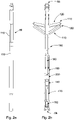
- Figures 2a and 2b show the device 50 of Figures 1a and 1b in more detail.
- Figure 2a shows the device 50 in a stowed configuration, e.g. when running to the well 20
- Figure 2b shows a perspective representation of device 50, together with a cross-section, in a deployed configuration when configured to mechanically and electrically engage with a wall surface of the metallic well structure 20.
- the device 50 comprises a body portion 100, which can be considered to be an elongated body portion for deployment in a well bore.
- the device 50 can be considered to have a proximal end 56 (nearer to surface) and a distal end 58 (further down in the well 20).
- the device 50 further comprises the mounting arrangement 110, described in relation to Figure 1a and 1b , and which will be described in further detail below.
- the mounting arrangement 110 comprises a plurality of deployment arms 120, which have a stowed configuration (e.g. for running into the well 20) and a deployed configuration in which the deployment arms 120 extend from the body portion 100.
- the device 50 comprises three deployment arms 120.
- the deployment arms 120 are regularly spaced around the device 50, or indeed around the body portion 100 of the device 50.
- two deployment arms 120 are shown, which are orientated 30 degrees off from the cross-section.
- the third deployment arm is of course not shown.
- the mounting arrangement 110 is controllably deployable from the body portion 100 using a drive unit 140.
- the drive unit 140 in this example is configured to actuate a sliding sleeve 150, which axially displaces along the body portion 100.
- the arms 120 are fixed at a position towards the proximal end 56 of the device 50, and free to move at a position towards the distal end 58 of the device, coupled to the sleeve 150.
- axial displacement of the sleeve 150 along the body portion 100 causes each of the arms 120 to extend to the deployed configuration, or indeed retract, when the sleeve is moved axially in the alternative direction.
- the drive unit 140 is operable to deploy and subsequently retract the mounting arrangement 110, in use.
- the drive unit 140 comprises a lead screw arrangement 160, which acts with the sleeve 150, so as to deploy - and in this example retract - the mounting arrangement 110.
- the drive unit 140, as well as the lead screw arrangement, are essentially packaged within the body portion 100 of the device 50.
- the drive unit 140 may be configured to deploy and/or retract the mounting arrangement 110 using a pressure system.
- a pressure system may act against a piston, or the like, in order to move the mounting arrangement 110 to the deployed/retracted configuration.
- the pressure system may utilise well pressure to actuate the mounting arrangement 110 (e.g. using a controllable valve, burst disc, etc. to permit well fluids to act upon a piston arrangement).
- the pressure system may comprise a pressure reservoir configured to act upon a piston arrangement, or the like, when controlled to do so.
- the device 50 comprises a battery unit 170 for powering the drive unit 140.
- the battery unit 170 may additionally be configured to power any on-board circuitry 180, which may be used by the device for the purposes of signalling, sensing, etc.
- the battery unit 170 and any circuitry 180 may be provided separate or otherwise external to the device 50.
- power and signalling may be provided from a sensor unit (e.g. gauge) connected to the device 50. In such a way, the component requirements of the device 50 itself may be minimised.
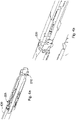
- FIG 3 shows in more detail the lead screw arrangement 160 together with a lead nut assembly 190.
- the lead nut assembly 190 comprises a seal arrangement and compression spring arrangement (e.g. a Belleville arrangement).
- the lead nut assembly 190 here is configured to compensate for material changes due to temperature variation, or the like.
- the drive unit 140 is configured to drive the lead screw arrangement 160, via a gearbox 200, which in this example is a reduction gearbox.
- Figures 4a and 4b shows a cross-sectional view of the proximal end 56 of the device 50.
- the deployment arms 120 are fixed towards the proximal end 56 of the device 50.
- the deployment arms 120 react from that fixed point, and cause radially outward displacement as is shown in Figure 2b .
- the device 50 further comprises a release mechanism 205 for releasing the deployment arms 120 from their deployed configuration (e.g. in the event of lack of control of or power to the drive unit).
- the release mechanism 205 operates together with a releasable member 210, which in this example is provided as a shear pin (other releasable members may be used).
- a releasable member 210 which in this example is provided as a shear pin (other releasable members may be used).
- an upward overpull action at the proximal end 56 of the device 50 can actuate the releasable member 210, and activate the release mechanism 205 to permit axial movement of the (previously) fixed arms 120.
- the device 50 may be configured such that a jarring action may be used. In such a manner, if need be, the device 50 and arms 120 can be retracted from their deployed configuration and permit retrieval to surface 30.
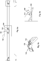
- FIG. 5a the mounting arrangement 110 in shown in the stowed configuration in which the deployment arms 120 are essentially flush with the body portion 100 of the device 50.
- the mounting arrangement 110 further comprises electrically conductive pads 130.
- the pads 130 are configured not only to engage mechanically a wall of the well structure 20, but also to provide electrical continuity between engaged metallic well structure 20 and the mounting arrangement 110, as will be further described.
- each of the deployment arms 120 is in communication with a conductive pad 130.
- Each of the conductive pads 130 can be considered to comprise a contact surface 132, which is configured to engage a wall surface, when deployed.
- the device 50 - and in particular the mounting arrangement 110 - is specifically configured to abrade a wall surface, when deployed.
- the contact surface 132 of the conductive pads comprise a plurality of serrations 134 or the like, configured to engage with and abrade a wall surface.
- the deployment arms 120 are rotatably attached to the conductive pads 130 at a linkage region 136.
- Figure 5b shows a perspective representation of the linkage region 136, when the deployment arms 120 and pads 130 are in a deployed configuration.
- the deployment arms also comprise a contact surface 122 for contact with a wall surface.
- the contact surface 122 here is also specifically configured for contact with a wall surface of a metallic well structure, when deployed.
- the contact surfaces 122 of the deployment arms 120 comprise a plurality of serrations 124, configured to engage with and abrade a wall surface.
- the device 50 is configured such that, rotation of the arms 120 relative to the conductive pads 130, which occurs as the mounting arrangement is extended towards a wall, causes relative counteraction (e.g. counter rotation) of the contact surfaces 122, 132 of the conductive pads 130 and of the deployment arms 120 at a wall surface of a metallic well structure.
- Such relative counteraction of contact surfaces 122, 132 can assist with abrading that wall surface in use.
- the surface can be scrubbed of debris, build up, corrosion or the like that may otherwise prevent or hinder a good signalling connection being made.
- the arms 120 may in some examples be retracted and re-deployed in order to further ablate the wall surface.
- the deployment arms 120 further comprise a connection element 250, e.g. to provide signalling connection from the arms 120 to the body portion 100.
- the connection element 250 is configured to orbit and maintain signalling connection with a socket arrangement 260 of the body portion 100.
- connection element 250 may maintain continuity with the body portion 100, and so maintain the signal path from the deployment arms and the conductive pads 130 to the body portion.
- the device 50 can be configured such that the signal path can be provided from the mounting arrangement 110 to the body portion 100.
- the deployment arms 120 are rotatably connected to the body portion 100 via a compliant connection 270.
- the compliant connection 270 can be used to permit some off-axially movement of the arms at the connection to the body portion 100. This can assist with maintaining signalling continuity between the deployment arms 120 and the body portion 100, and potentially avoid open circuits or poor communication at that point due to wear.
- the mounting arrangement 110 can be configured to retain the device 50 at a location at a metallic well structure 20, for example, by mechanically engaging with a wall surface of that metallic well structure 20. Further, the mounting arrangement 110 may be controllably deployable from the body portion 100 such that the conductive pads provide electrical continuity between engaged metallic well structure 20 and the mounting arrangement 110. In doing so, the device 50 is configured such that there is provided an electrical signal path between the one or more of the conductive pads 130 and the body portion 100 so as to provide electrical continuity between metallic well structure 20 and body portion 100, when deployed.
- Figure 6 shows an example of the device 50 deployed in which an electrical signal path 300 is provided.
- the body portion 100 may comprise a connection point 400 for electrically connecting the device 50 to further apparatus.
- the electrical signal path 300 may be provided between the conductive pads 130 and the connection point 400 so as to allow for electrical continuity between metallic well structure 20 and further apparatus (e.g. further tools, devices, e-lines, etc. connected to the device 50 at the connection point 400).
- the device 50 may comprise a plurality of connection points, as is shown in Figure 6 . Some or all connection points 400 may be selectable (e.g. by the device) in order to direct signals to one or more apparatus attached at particular connections points 400.
- the battery unit 170 may be configured to be chargeable from electrical signals being communicated using the electrical signal path 300.
- the electrical contact device 50 can be initially deployed at a particular location in well, as mentioned in relation to Figure 1a .
- the mounting arrangement can be controllably deployed so as to mechanically and electrically engage with a wall surface of that metallic well structure 20.
- the deployment may be a timed deployment, or a pressure-based deployment, or controlled using signalling (e.g. via an e-line).
- electrical signals can be communicated to/from the well structure using an electrical signal path 300 formed between the device 50 and the metallic well structure 20, e.g. using the mounting arrangement 110.
- the device 50 may be used to abrade the wall surface of a well structure 20 so as to provide signalling continuity between that engaged well structure 20 and the mounting arrangement 110.
- the device 50 may assess the continuity between the device 50 and the metallic well structure 20.
- the continuity between the device 50 and the metallic well structure 20 may be assessed by measuring the impedance along the electrical signal path 300 or the like, e.g. at the device/well structure.
- a threshold e.g. a predefined threshold
- the device 50 may be configured to permit controllable retraction and re-deployment of the mounting arrangement 110. In doing so, the device 50 may be re-deployed to a different location in the well 10, prior to re-deploying the mounting arrangement 110, or indeed re-deployed at the same location in order to further ablate the wall surface.
- the device 50 may be additionally or alternatively configured to communicate acoustic signals via the well structure.
- the conductive pads 130 of the mounting arrangement 110 may provide acoustic continuity between engaged well structure and the mounting arrangement 110.
- the pads 130 and device 50 may be configured to provide an acoustic impedance match to the well structure 20 such that there is provided a signal path (in this example acoustic signal path) between one or more of the conductive pads 130 and the body portion 100. It will be appreciated that, as above, abrasion performed on a wall surface of the well structure 20 may improve acoustic continuity between that engaged well structure 20 and the mounting arrangement 110.
- the device 50 may comprise a signal receiver/transmitter (e.g. a transceiver) to communicate signals to/from the engaged well structure 20.
- a signal receiver/transmitter e.g. a transceiver
- the device 50 may be configured, in use, to couple with further apparatus so as to communicate signals to and/or from that further apparatus and well structure 20, which can included data and/or power electrical signals to/from well structure 20. While the device 50 may be used alone, in other examples, the device 50 may be comprised with a deployable string (e.g. a tool string).
- a deployable string e.g. a tool string
- Figure 7a shows and example of a string 500 that comprises a contact device 50, as described above, and in this case the string 500 may comprise two or more such contact devices 50a, 50b.
- the contact devices 50a, 50b are axially displaced from one another along the string 500.
- Such a deployable string 500 may comprise one or more downhole gauges, casing collar locators or survey tools, or other such tools as may be desirable to use, or the like.
- the device 50 When deployed, the device 50 may be used to support and maintain the string 500 at a particular location in the well.
- the two contact devices 50a, 50b are separately operable (e.g. independently operable) in order to deploy and retain the string 500 at a position in a well structure 20.
- the each of the contact devices 50a, 50b may be operable separately so as to be able to control deployment of one device 50a, and then the other device 50b.
- one device 50a can initially be set, and hold the string 500, and then if need be the other can be deployed.
- the multiple devices 50 may be set independently at different location in a well, as is shown in Figure 7b .
- one device 50 is positioned lower in the well, and communicates data to a second device at a higher location in the well. Signals can then be communicated to surface via a cable, or the like.
- the devices may be positioned either side of a barrier, for example. In some examples, both electrical and acoustic signals may be communicated between the devices 50a, 50b.
- the device 50 may be configured so as to be movable from a first location to second location within a well and be deployed so as to mechanically and electrically engage with a wall surface of that metallic well structure 20. Electrical signals can be communicated from the well structure 20 to the battery unit 170 of the device using an electrical signal path 300 formed between the device 50 and the metallic well structure 20, e.g. via the mounting arrangement 110. In such a way, the device 50 may be repeatedly reset, and redeployed. Further, the device 50 may be used to communicate power signals to battery units of further devices or apparatus in the well.
- power signals may be communicated using the well structure, via a mounted device 50, to a battery unit of further apparatus (e.g. gauges, such as existing fixed gauges, or the like).
- further apparatus/battery units can therefore be external to the device 50, but nevertheless in electrical communication with the device 50 so as to communicate signals therewith.
Landscapes
- Engineering & Computer Science (AREA)
- Life Sciences & Earth Sciences (AREA)
- Mining & Mineral Resources (AREA)
- Physics & Mathematics (AREA)
- Geology (AREA)
- Remote Sensing (AREA)
- Environmental & Geological Engineering (AREA)
- Fluid Mechanics (AREA)
- General Life Sciences & Earth Sciences (AREA)
- Geochemistry & Mineralogy (AREA)
- Geophysics (AREA)
- Electromagnetism (AREA)
- Mechanical Engineering (AREA)
- Near-Field Transmission Systems (AREA)
- Charge And Discharge Circuits For Batteries Or The Like (AREA)
Claims (19)
- Einsetzbare elektrische Kontaktvorrichtung (50), Folgendes umfassend:einen Körperabschnitt (100);eine Montageanordnung (110), welche kontrollierbar von dem Körperabschnitt (100) aus einsetzbar ist, wobei die Montageanordnung konfiguriert ist, um die Vorrichtung in einer Position an einer metallischen Bohrlochstruktur (20) zu halten, durch mechanisches Eingreifen mit einer Wandoberfläche der metallischen Bohrlochstruktur (20), wobei die Montageanordnung (110) elektrisch leitfähige Kontaktflächen (130) zum Bereitstellen elektrischer Kontinuität zwischen der in Eingriff befindlichen metallischen Bohrlochstruktur (20) und der Montageanordnung (110) umfasst; undwobei die Vorrichtung (50) dergestalt konfiguriert ist, dass ein elektrischer Signalpfad (300) zwischen einer oder mehreren der leitfähigen Kontaktflächen (130) und dem Körperabschnitt (100) bereitgestellt wird, um eine elektrische Kontinuität zwischen der metallischen Bohrlochstruktur (20) und dem Körperabschnitt im eingesetzten Zustand bereitzustellen,wobei die Vorrichtung (50) dazu konfiguriert ist, während des Einsetzens eine Wandoberfläche einer Bohrlochstruktur (20) abzureiben, um eine elektrische Kontinuität zwischen dieser in Eingriff befindlichen Bohrlochstruktur (20) und der Montageanordnung (110) bereitzustellen,wobei die leitfähigen Kontaktflächen (130) eine Kontaktoberfläche (132) umfassen, welche konfiguriert ist, um im eingesetzten Zustand mit einer Wandoberfläche in Eingriff zu gehen und diese abzureiben, wobei die Kontaktoberfläche (132) eine Vielzahl von Zacken (134) umfasst, welche konfiguriert ist, um mit einer Wandoberfläche in Eingriff zu gehen und diese abzureiben, undwobei die Montageanordnung (110) kontrollierbar von dem Körperabschnitt (100) aus unter Verwendung eine Antriebseinheit (140) einsetzbar ist, welche innerhalb des Körperabschnitts (100) der Vorrichtung (50) verpackt ist, wobei die Antriebseinheit (140) bedienbar ist, um die Montageanordnung (110) einzusetzen.
- Vorrichtung (50) nach Anspruch 1, wobei der Körperabschnitt (100) einen Verbindungspunkt (400) zur elektrischen Verbindung der Vorrichtung (50) mit einem weiteren Gerät umfasst, und wobei der elektrische Signalpfad (300) zwischen den leitfähigen Kontaktflächen (130) und dem Verbindungspunkt (400) bereitgestellt ist, um elektrische Kontinuität zwischen der metallischen Bohrlochstruktur (20) und einem weiteren Gerät zu ermöglichen.
- Vorrichtung (50) nach Anspruch 1, wobei die Montageanordnung (110) Einsetzarme (120) umfasst, wobei die Einsetzarme (120) eine verstaute Konfiguration und eine eingesetzte Konfiguration aufweisen, in welcher die Arme (120) sich vom Körperabschnitt (100) weg erstrecken, um die leitfähigen Kontaktflächen (130) in elektrischen Kontakt mit der metallischen Bohrlochstruktur (20) zu drängen.
- Vorrichtung (50) nach Anspruch 3, wobei die Einsetzarme (120) drehbar an den leitfähigen Kontaktflächen (130) an einem Verbindungsbereich (136) befestigt sind, und wobei einige oder alle der Arme (120) eine Kontaktoberfläche (122) an dem Verbindungsbereich (136) zum Kontakt mit einer Wandoberfläche während des Einsetzens umfassen.
- Vorrichtung (50) nach Anspruch 4, wobei die Kontaktoberfläche (122) der Einsetzarme (120) eine Vielzahl von Zacken (134) umfasst, welche konfiguriert ist, um mit einer Wandoberfläche in Eingriff zu gehen und diese abzureiben.
- Vorrichtung (50) nach Anspruch 4 oder 5, wobei die Montageanordnung (110) dergestalt konfiguriert ist, dass eine Rotation der Arme (120) in Bezug auf die leitfähigen Kontaktflächen (130) eine Gegenwirkung der Kontaktoberflächen der leitfähigen Kontaktflächen (130) und der Einsetzarme (120) an einer Wandoberfläche einer metallischen Bohrlochstruktur (20) dergestalt verursacht, dass ein Abreiben dieser Wandoberfläche unterstützt wird.
- Vorrichtung (50) nach einem der Ansprüche 3 bis 6, wobei die Einsetzarme (120) ein Verbindungselement (250) umfassen, welches konfiguriert ist, um eine Buchsenanordnung (260) des Körperabschnittes (100) zu umkreisen und eine elektrische Verbindung damit aufrechtzuerhalten, wenn die Arme (120) kontrollierbar zwischen der verstauten und der eingesetzten Konfiguration bewegt werden.
- Vorrichtung (50) nach Anspruch 7, wobei der elektrische Signalpfad (300) von der Montageanordnung (110) zum Körperabschnitt (100) über die Buchsenanordnung (260) bereitgestellt ist.
- Vorrichtung (50) nach einem der Ansprüche 3 bis 8, wobei die Einsetzarme (120) drehbar mit dem Körperabschnitt (100) über eine nachgiebige Verbindung (270) verbunden sind.
- Vorrichtung (50) nach dem vorhergehenden Anspruch, wobei die Antriebseinheit (140) bedienbar ist, um die Montageanordnung (110) im Gebrauch einzusetzen und anschließend zurückzuziehen.
- Vorrichtung (50) nach Anspruch 10, wobei die Antriebseinheit (140) konfiguriert ist, um bedienbar zu sein, um die Montageanordnung (110) einzusetzen und anschließend zurückzuziehen, und anschließend die Montageanordnung (110) weiter dergestalt einzusetzen, dass ein Abreiben einer Wandoberfläche der Bohrlochstruktur (20) unterstützt wird.
- Vorrichtung (50) nach einem der vorhergehenden Ansprüche, wobei die Vorrichtung (50) im Gebrauch konfiguriert ist, um sich mit einem weiteren Gerät dergestalt zu koppeln, dass elektrische Signale an dieses und/oder vom diesem weiteren Gerät und der metallischen Bohrlochstruktur (20) kommuniziert werden.
- Vorrichtung (50) nach einem der vorhergehenden Ansprüche, wobei die leitfähigen Kontaktflächen (130) zusätzlich konfiguriert sind, um akustische Kontinuität zwischen einer in Eingriff befindlichen Bohrlochstruktur (20) und der Montageanordnung (110) dergestalt bereitzustellen, dass ein akustischer Signalpfad zwischen einer oder mehreren der leitfähigen Kontaktflächen (130) und dem Körperabschnitt (100) bereitgestellt wird, wodurch akustische Signalisierungskontinuität zwischen der Bohrlochstruktur (20) und dem Körperabschnitt (100) im eingesetzten Zustand bereitgestellt wird.
- Vorrichtung (50) nach einem der vorhergehenden Ansprüche, wobei die Antriebseinheit (140) Folgendes umfasst:eine Führungsschraubenanordnung (160), welche konfiguriert ist, um die Montageanordnung (110) einzusetzen und zurückzuziehen, oderein Drucksystem, welches konfiguriert ist, um die Montageanordnung (110) einzusetzen und/oder zurückzuziehen.
- Einsetzbarer Strang (500), umfassend zwei oder mehr Kontaktvorrichtungen (50a, 50b) nach einem der vorhergehenden Ansprüche.
- Einsetzbarer Strang (500) nach Anspruch 15, wobei zwei oder mehr der Kontaktvorrichtungen (50a, 50b) unabhängig bedienbar sind, um den Strang (500) an einer Position in einer Bohrlochstruktur (20) einzusetzen und zurückzuhalten.
- Verwendung der Vorrichtung (50) nach einem der Ansprüche 1 bis 15 zum Kommunizieren von Signalen in einem Bohrloch (10).
- Verfahren zum Kommunizieren elektrischer Signale in einem Bohrloch (10), wobei das Verfahren Folgendes umfasst:Einsetzen einer elektrischen Kontaktvorrichtung (50) an einer Position in einem Bohrloch (10),kontrollierbares Einsetzen einer Montageanordnung (110) der Vorrichtung (50), damit diese mechanisch und elektrisch mit einer Wandoberfläche dieser metallischen Bohrlochstruktur (20) in Eingriff geht, wobei die Montageanordnung (110) kontrollierbar von einem Körperabschnitt (100) der Vorrichtung (50) unter Verwendung einer Antriebseinheit (140) einsetzbar ist, welche innerhalb des Körperabschnittes (100) der Vorrichtung (50) verpackt ist, wobei die Antriebseinheit (140) bedienbar ist, um die Montageanordnung (110) einzusetzen;Abreiben der Wandoberfläche einer Bohrlochstruktur (20) zum Bereitstellen einer elektrischen Kontinuität zwischen dieser in Eingriff befindlichen Bohrlochstruktur (20) und der Montageanordnung (110), wobei die Montageanordnung (110) elektrisch leitfähige Kontaktflächen (130) umfasst, um elektrische Kontinuität zwischen der in Eingriff befindlichen Bohrlochstruktur (20) und der Montageanordnung (110) bereitzustellen, wobei die leitfähigen Kontaktflächen (130) eine Kontaktoberfläche (132) umfassen, welche konfiguriert ist, um im eingesetzten Zustand mit einer Wandoberfläche in Eingriff zu gehen und diese abzureiben, und wobei die Kontaktoberfläche (132) eine Vielzahl von Zacken (134) umfasst, welche konfiguriert ist, um mit einer Wandoberfläche in Eingriff zu gehen und diese abzureiben; undKommunizieren elektrischer Signale an die/von der Bohrlochstruktur (20) unter Verwendung eines elektrischen Signalpfades (300), welcher zwischen der Vorrichtung (50) und der metallischen Bohrlochstruktur (20) gebildet ist, unter Verwendung der Montageanordnung.
- Verfahren nach Anspruch 18, ferner umfassend, nach dem Ineingriffbringen, Beurteilen der Kontinuität zwischen der Vorrichtung (50) und der metallischen Bohrlochstruktur (20), wobei optionsweise die Kontinuität zwischen der Vorrichtung (50) und der metallischen Bohrlochstruktur (20) durch Messen der Impedanz entlang des elektrischen Signalpfades (300) beurteilt wird.
Applications Claiming Priority (2)
| Application Number | Priority Date | Filing Date | Title |
|---|---|---|---|
| GBGB1718255.1A GB201718255D0 (en) | 2017-11-03 | 2017-11-03 | Deployable devices and methods |
| PCT/GB2018/053129 WO2019086851A1 (en) | 2017-11-03 | 2018-10-30 | Deployable devices and methods |
Publications (2)
| Publication Number | Publication Date |
|---|---|
| EP3704352A1 EP3704352A1 (de) | 2020-09-09 |
| EP3704352B1 true EP3704352B1 (de) | 2022-10-12 |
Family
ID=60664842
Family Applications (1)
| Application Number | Title | Priority Date | Filing Date |
|---|---|---|---|
| EP18797078.5A Active EP3704352B1 (de) | 2017-11-03 | 2018-10-30 | Einsetzbare vorrichtungen und verfahren |
Country Status (6)
| Country | Link |
|---|---|
| US (2) | US11933167B2 (de) |
| EP (1) | EP3704352B1 (de) |
| AU (1) | AU2018361802C1 (de) |
| CA (1) | CA3081160A1 (de) |
| GB (1) | GB201718255D0 (de) |
| WO (1) | WO2019086851A1 (de) |
Citations (10)
| Publication number | Priority date | Publication date | Assignee | Title |
|---|---|---|---|---|
| US20020053434A1 (en) | 1999-07-07 | 2002-05-09 | Kuo-Chiang Chen | Downhole anchoring tools conveyed by non-rigid carriers |
| US20030024704A1 (en) | 2000-03-02 | 2003-02-06 | Hirsch John M | Use of downhole high pressure gas in a gas-lift well |
| US20080007422A1 (en) * | 2004-12-03 | 2008-01-10 | Hudson Steven M | Downhole Communication |
| US20100155052A1 (en) | 2003-11-07 | 2010-06-24 | Peak Well Services Pty Ltd | Downhole Tool and Running Tool System for Retrievably Setting a Downhole Tool at Locations Within a Well Bore |
| US8151902B2 (en) | 2009-04-17 | 2012-04-10 | Baker Hughes Incorporated | Slickline conveyed bottom hole assembly with tractor |
| US20130249704A1 (en) | 2010-09-15 | 2013-09-26 | Peter S. Aronstam | Expandable tubular antenna feed line for through casing e/m communication |
| WO2014178725A1 (en) | 2013-05-03 | 2014-11-06 | Ingineering As | Setting tool and method of using same |
| WO2015155617A1 (en) | 2014-04-08 | 2015-10-15 | Acoustic Data Limited | Gauge hanger |
| US20150369038A1 (en) | 2013-05-17 | 2015-12-24 | Halliburton Manfacturing and Services Limited | Determining stuck point of tubing in a wellbore |
| WO2016195682A1 (en) | 2015-06-03 | 2016-12-08 | Halliburton Energy Services, Inc. | System and method for a downhole hanger assembly |
Family Cites Families (17)
| Publication number | Priority date | Publication date | Assignee | Title |
|---|---|---|---|---|
| US3379963A (en) * | 1965-04-02 | 1968-04-23 | Schlumberger Technology Corp | Well logging pad member constructed to contorm to borehole wall curvature |
| US3379964A (en) * | 1965-04-02 | 1968-04-23 | Schlumberger Technology Corp | Well logging pad structure having pivotally interconnected members |
| US4192380A (en) * | 1978-10-02 | 1980-03-11 | Dresser Industries, Inc. | Method and apparatus for logging inclined earth boreholes |
| FR2448621A1 (fr) * | 1979-02-09 | 1980-09-05 | Inst Francais Du Petrole | Sonde a patin rotatif pour effectuer des mesures dans un forage |
| US4914826A (en) * | 1989-05-19 | 1990-04-10 | Schlumberger Technology Corporation | Decentralized well logging apparatus for measuring the diameters of a borehole along its perpendicular diametrical axes |
| US5302781A (en) * | 1993-02-05 | 1994-04-12 | Schlumberger Technology Corporation | Sidewall contact temperature tool including knife edge sensors for cutting through mudcake and measuring formation temperature |
| US5680049A (en) * | 1995-12-11 | 1997-10-21 | Western Atlas International, Inc. | Apparatus for measuring formation resistivity through a conductive casing having a coaxial tubing inserted therein |
| US8408287B2 (en) * | 2010-06-03 | 2013-04-02 | Electro-Petroleum, Inc. | Electrical jumper for a producing oil well |
| US8468882B2 (en) * | 2010-11-30 | 2013-06-25 | Schlumberger Technology Corporation | Method and apparatus for logging a wellbore |
| WO2014018959A1 (en) * | 2012-07-27 | 2014-01-30 | US Seismic Systems, Inc. | Remotely actuated clamping devices for borehole seismic sensing systems and methods of operating the same |
| GB2506123C (en) * | 2012-09-19 | 2024-02-21 | Expro North Sea Ltd | Downhole communication |
| WO2015105505A1 (en) * | 2014-01-10 | 2015-07-16 | Peter S Aronstam | Wireless communication platform for operation in conduits |
| US10254432B2 (en) * | 2014-06-24 | 2019-04-09 | Schlumberger Technology Corporation | Multi-electrode electric field downhole logging tool |
| WO2016085506A1 (en) * | 2014-11-26 | 2016-06-02 | Rem Scientific Enterprises, Inc | Systems and methods for reducing casing noise effects |
| US10705242B2 (en) * | 2015-02-26 | 2020-07-07 | Halliburton Energy Services, Inc. | Downhole sensor deployment assembly |
| WO2019040470A1 (en) * | 2017-08-22 | 2019-02-28 | Baker Hughes, A Ge Company, Llc | SYSTEM AND METHOD FOR TOOL POSITIONING FOR DRILLING WELLS |
| US20200102803A1 (en) * | 2018-09-30 | 2020-04-02 | Stuart Petroleum Testers, Inc. Dba Stuart Pressure Control | Ball dropper |
-
2017
- 2017-11-03 GB GBGB1718255.1A patent/GB201718255D0/en not_active Ceased
-
2018
- 2018-10-30 AU AU2018361802A patent/AU2018361802C1/en active Active
- 2018-10-30 WO PCT/GB2018/053129 patent/WO2019086851A1/en not_active Ceased
- 2018-10-30 US US16/761,125 patent/US11933167B2/en active Active
- 2018-10-30 CA CA3081160A patent/CA3081160A1/en active Pending
- 2018-10-30 EP EP18797078.5A patent/EP3704352B1/de active Active
-
2021
- 2021-09-29 US US17/489,170 patent/US11828170B2/en active Active
Patent Citations (10)
| Publication number | Priority date | Publication date | Assignee | Title |
|---|---|---|---|---|
| US20020053434A1 (en) | 1999-07-07 | 2002-05-09 | Kuo-Chiang Chen | Downhole anchoring tools conveyed by non-rigid carriers |
| US20030024704A1 (en) | 2000-03-02 | 2003-02-06 | Hirsch John M | Use of downhole high pressure gas in a gas-lift well |
| US20100155052A1 (en) | 2003-11-07 | 2010-06-24 | Peak Well Services Pty Ltd | Downhole Tool and Running Tool System for Retrievably Setting a Downhole Tool at Locations Within a Well Bore |
| US20080007422A1 (en) * | 2004-12-03 | 2008-01-10 | Hudson Steven M | Downhole Communication |
| US8151902B2 (en) | 2009-04-17 | 2012-04-10 | Baker Hughes Incorporated | Slickline conveyed bottom hole assembly with tractor |
| US20130249704A1 (en) | 2010-09-15 | 2013-09-26 | Peter S. Aronstam | Expandable tubular antenna feed line for through casing e/m communication |
| WO2014178725A1 (en) | 2013-05-03 | 2014-11-06 | Ingineering As | Setting tool and method of using same |
| US20150369038A1 (en) | 2013-05-17 | 2015-12-24 | Halliburton Manfacturing and Services Limited | Determining stuck point of tubing in a wellbore |
| WO2015155617A1 (en) | 2014-04-08 | 2015-10-15 | Acoustic Data Limited | Gauge hanger |
| WO2016195682A1 (en) | 2015-06-03 | 2016-12-08 | Halliburton Energy Services, Inc. | System and method for a downhole hanger assembly |
Non-Patent Citations (8)
| Title |
|---|
| ANONYMOUS: "Barracuda HEX Gauge Hanger System ", ACOUSTIC DATA, 25 October 2017 (2017-10-25), pages 1 - 5, XP093128034, Retrieved from the Internet <URL:https://web.archive.org/web/20171025193514/http://acousticdata.com/high-expansion-gauge-hanger/> [retrieved on 20240206] |
| ANONYMOUS: "High expansion gauge hanger ", INTERWELL, 31 October 2017 (2017-10-31), pages 1, XP093128056 |
| ANONYMOUS: "High Expansion Gauge Hanger", OMEGA WELL INTERVENTION, 14 October 2017 (2017-10-14), pages 1 - 2, XP093128073 |
| ANONYMOUS: "Packers", PETROWILKI (SOCIETY OF PETROLEUM ENGINEERS), 21 June 2017 (2017-06-21), pages 1 - 15, XP093128028, Retrieved from the Internet <URL:https://petrowiki.spe.org/Packers> |
| CHAMPION BRIAN PHILLIP, ALLISON J. STRONG; NEIL MOODIE: "Mungo Platform: A New Wireless Retrofit Solution to Restore Real Time BHP / BHT Data After a Permanently Installed Monitoring System has Failed-A North Sea Case History", SPE OFFSHORE EUROPE OIL AND GAS CONFERENCE AND EXHIBITION, 8 September 2009 (2009-09-08), pages 1 - 10, XP055837089, DOI: 10.2118/124100-MS |
| HALLIBURTON: "Halliburton's High-Expansion Gauge Hanger", YOUTUBE, 19 August 2013 (2013-08-19), XP093128018, Retrieved from the Internet <URL:https://www.youtube.com/watch?v=YiqWB_gfPho> [retrieved on 20240206] |
| ZBITOWSKY RON ET AL: "A Versatile High-Expansion Hanger Device for Suspension of Downhole Devices during Performance of Critical Asset Diagnostics and Enhancement Methods", SPE/ICOTA COILED TUBING AND WELL INTERVENTION CONFERENCE AND EXHIBITION, 25 March 2004 (2004-03-25), pages 1 - 9, XP055837074, DOI: 10.2118/168239-MS |
| ZBITOWSKY RON ET AL: "A Versatile High-Expansion Hanger Device for Suspension of Downhole Devices during Performance of Critical Asset Diagnostics and Enhancement Methods", SPE/ICOTA COILED TUBING AND WELL INTERVENTION CONFERENCE AND EXHIBITION, 25 March 2004 (2004-03-25), pages 1 - 9, XP055837074, Retrieved from the Internet <URL:http://onepetro.org/SPECTWI/proceedings-pdf/doi/10.2118/168239-MS/1475384/spe-168239-ms.pdf> [retrieved on 20210803], DOI: 10.2118/168239-MS * |
Also Published As
| Publication number | Publication date |
|---|---|
| US20210238993A1 (en) | 2021-08-05 |
| WO2019086851A1 (en) | 2019-05-09 |
| US20220018246A1 (en) | 2022-01-20 |
| AU2018361802A1 (en) | 2020-05-21 |
| GB201718255D0 (en) | 2017-12-20 |
| EP3704352A1 (de) | 2020-09-09 |
| US11933167B2 (en) | 2024-03-19 |
| AU2018361802C1 (en) | 2025-04-17 |
| US11828170B2 (en) | 2023-11-28 |
| AU2018361802B2 (en) | 2024-07-25 |
| CA3081160A1 (en) | 2019-05-09 |
Similar Documents
| Publication | Publication Date | Title |
|---|---|---|
| CA2857870C (en) | A logging tool and method of its use | |
| US10900305B2 (en) | Instrument line for insertion in a drill string of a drilling system | |
| US10392889B2 (en) | Downhole cable grab assembly and method of use | |
| US9976371B2 (en) | Pipe conveyed logging while fishing | |
| CA2584827A1 (en) | System and method for releasing and retrieving memory tool with wireline in well pipe | |
| CA2948380A1 (en) | Multi-contact connector assembly | |
| US20140338886A1 (en) | Smart Drop-Off Tool and Hang-Off Tool for a Logging String | |
| CN110678625B (zh) | 自回缩壁接触测井传感器 | |
| CA2564598A1 (en) | Plug setting and retrieving apparatus | |
| WO2010065490A1 (en) | Method and system for deploying sensors in a well bore using a latch and mating element | |
| US9051817B2 (en) | Pipe conveyed extendable well logging tool with protector | |
| US8887817B2 (en) | Intermediate disconnection tool to be placed in a shuttle lowered into a well for exploiting a fluid, and related shuttle and method | |
| EP3704352B1 (de) | Einsetzbare vorrichtungen und verfahren | |
| US20210079787A1 (en) | Monitoring of downhole components during deployment | |
| CA2861621C (en) | Wireless drill string disconnect | |
| US20160298398A1 (en) | Multi-segment instrument line for instrument in drill string | |
| US20200378204A1 (en) | Hybrid Telemetry System for Drilling Operations | |
| US10400532B2 (en) | Downhole tool anchoring device | |
| WO2016090110A1 (en) | Cable protector gauge carrier for reading reservoir pressure through cement | |
| US20150129220A1 (en) | Pump actuated jar for downhole sampling tools |
Legal Events
| Date | Code | Title | Description |
|---|---|---|---|
| STAA | Information on the status of an ep patent application or granted ep patent |
Free format text: STATUS: UNKNOWN |
|
| STAA | Information on the status of an ep patent application or granted ep patent |
Free format text: STATUS: THE INTERNATIONAL PUBLICATION HAS BEEN MADE |
|
| PUAI | Public reference made under article 153(3) epc to a published international application that has entered the european phase |
Free format text: ORIGINAL CODE: 0009012 |
|
| STAA | Information on the status of an ep patent application or granted ep patent |
Free format text: STATUS: REQUEST FOR EXAMINATION WAS MADE |
|
| 17P | Request for examination filed |
Effective date: 20200501 |
|
| AK | Designated contracting states |
Kind code of ref document: A1 Designated state(s): AL AT BE BG CH CY CZ DE DK EE ES FI FR GB GR HR HU IE IS IT LI LT LU LV MC MK MT NL NO PL PT RO RS SE SI SK SM TR |
|
| AX | Request for extension of the european patent |
Extension state: BA ME |
|
| DAV | Request for validation of the european patent (deleted) | ||
| DAX | Request for extension of the european patent (deleted) | ||
| STAA | Information on the status of an ep patent application or granted ep patent |
Free format text: STATUS: EXAMINATION IS IN PROGRESS |
|
| 17Q | First examination report despatched |
Effective date: 20210315 |
|
| TPAC | Observations filed by third parties |
Free format text: ORIGINAL CODE: EPIDOSNTIPA |
|
| REG | Reference to a national code |
Ref country code: DE Ref legal event code: R079 Ref document number: 602018041745 Country of ref document: DE Free format text: PREVIOUS MAIN CLASS: E21B0047120000 Ipc: E21B0047130000 |
|
| GRAP | Despatch of communication of intention to grant a patent |
Free format text: ORIGINAL CODE: EPIDOSNIGR1 |
|
| STAA | Information on the status of an ep patent application or granted ep patent |
Free format text: STATUS: GRANT OF PATENT IS INTENDED |
|
| RIC1 | Information provided on ipc code assigned before grant |
Ipc: E21B 17/10 20060101ALI20220321BHEP Ipc: E21B 47/13 20120101AFI20220321BHEP |
|
| INTG | Intention to grant announced |
Effective date: 20220422 |
|
| GRAS | Grant fee paid |
Free format text: ORIGINAL CODE: EPIDOSNIGR3 |
|
| GRAA | (expected) grant |
Free format text: ORIGINAL CODE: 0009210 |
|
| STAA | Information on the status of an ep patent application or granted ep patent |
Free format text: STATUS: THE PATENT HAS BEEN GRANTED |
|
| AK | Designated contracting states |
Kind code of ref document: B1 Designated state(s): AL AT BE BG CH CY CZ DE DK EE ES FI FR GB GR HR HU IE IS IT LI LT LU LV MC MK MT NL NO PL PT RO RS SE SI SK SM TR |
|
| REG | Reference to a national code |
Ref country code: GB Ref legal event code: FG4D |
|
| REG | Reference to a national code |
Ref country code: CH Ref legal event code: EP |
|
| REG | Reference to a national code |
Ref country code: DE Ref legal event code: R096 Ref document number: 602018041745 Country of ref document: DE |
|
| REG | Reference to a national code |
Ref country code: IE Ref legal event code: FG4D |
|
| REG | Reference to a national code |
Ref country code: AT Ref legal event code: REF Ref document number: 1524291 Country of ref document: AT Kind code of ref document: T Effective date: 20221115 |
|
| REG | Reference to a national code |
Ref country code: NO Ref legal event code: T2 Effective date: 20221012 |
|
| REG | Reference to a national code |
Ref country code: LT Ref legal event code: MG9D |
|
| REG | Reference to a national code |
Ref country code: NL Ref legal event code: MP Effective date: 20221012 |
|
| REG | Reference to a national code |
Ref country code: AT Ref legal event code: MK05 Ref document number: 1524291 Country of ref document: AT Kind code of ref document: T Effective date: 20221012 |
|
| PG25 | Lapsed in a contracting state [announced via postgrant information from national office to epo] |
Ref country code: NL Free format text: LAPSE BECAUSE OF FAILURE TO SUBMIT A TRANSLATION OF THE DESCRIPTION OR TO PAY THE FEE WITHIN THE PRESCRIBED TIME-LIMIT Effective date: 20221012 |
|
| PG25 | Lapsed in a contracting state [announced via postgrant information from national office to epo] |
Ref country code: SE Free format text: LAPSE BECAUSE OF FAILURE TO SUBMIT A TRANSLATION OF THE DESCRIPTION OR TO PAY THE FEE WITHIN THE PRESCRIBED TIME-LIMIT Effective date: 20221012 Ref country code: PT Free format text: LAPSE BECAUSE OF FAILURE TO SUBMIT A TRANSLATION OF THE DESCRIPTION OR TO PAY THE FEE WITHIN THE PRESCRIBED TIME-LIMIT Effective date: 20230213 Ref country code: LT Free format text: LAPSE BECAUSE OF FAILURE TO SUBMIT A TRANSLATION OF THE DESCRIPTION OR TO PAY THE FEE WITHIN THE PRESCRIBED TIME-LIMIT Effective date: 20221012 Ref country code: FI Free format text: LAPSE BECAUSE OF FAILURE TO SUBMIT A TRANSLATION OF THE DESCRIPTION OR TO PAY THE FEE WITHIN THE PRESCRIBED TIME-LIMIT Effective date: 20221012 Ref country code: ES Free format text: LAPSE BECAUSE OF FAILURE TO SUBMIT A TRANSLATION OF THE DESCRIPTION OR TO PAY THE FEE WITHIN THE PRESCRIBED TIME-LIMIT Effective date: 20221012 Ref country code: AT Free format text: LAPSE BECAUSE OF FAILURE TO SUBMIT A TRANSLATION OF THE DESCRIPTION OR TO PAY THE FEE WITHIN THE PRESCRIBED TIME-LIMIT Effective date: 20221012 |
|
| REG | Reference to a national code |
Ref country code: DE Ref legal event code: R119 Ref document number: 602018041745 Country of ref document: DE |
|
| PG25 | Lapsed in a contracting state [announced via postgrant information from national office to epo] |
Ref country code: RS Free format text: LAPSE BECAUSE OF FAILURE TO SUBMIT A TRANSLATION OF THE DESCRIPTION OR TO PAY THE FEE WITHIN THE PRESCRIBED TIME-LIMIT Effective date: 20221012 Ref country code: PL Free format text: LAPSE BECAUSE OF FAILURE TO SUBMIT A TRANSLATION OF THE DESCRIPTION OR TO PAY THE FEE WITHIN THE PRESCRIBED TIME-LIMIT Effective date: 20221012 Ref country code: LV Free format text: LAPSE BECAUSE OF FAILURE TO SUBMIT A TRANSLATION OF THE DESCRIPTION OR TO PAY THE FEE WITHIN THE PRESCRIBED TIME-LIMIT Effective date: 20221012 Ref country code: IS Free format text: LAPSE BECAUSE OF FAILURE TO SUBMIT A TRANSLATION OF THE DESCRIPTION OR TO PAY THE FEE WITHIN THE PRESCRIBED TIME-LIMIT Effective date: 20230212 Ref country code: HR Free format text: LAPSE BECAUSE OF FAILURE TO SUBMIT A TRANSLATION OF THE DESCRIPTION OR TO PAY THE FEE WITHIN THE PRESCRIBED TIME-LIMIT Effective date: 20221012 Ref country code: GR Free format text: LAPSE BECAUSE OF FAILURE TO SUBMIT A TRANSLATION OF THE DESCRIPTION OR TO PAY THE FEE WITHIN THE PRESCRIBED TIME-LIMIT Effective date: 20230113 |
|
| REG | Reference to a national code |
Ref country code: CH Ref legal event code: PL |
|
| P01 | Opt-out of the competence of the unified patent court (upc) registered |
Effective date: 20230512 |
|
| REG | Reference to a national code |
Ref country code: BE Ref legal event code: MM Effective date: 20221031 |
|
| PG25 | Lapsed in a contracting state [announced via postgrant information from national office to epo] |
Ref country code: LU Free format text: LAPSE BECAUSE OF NON-PAYMENT OF DUE FEES Effective date: 20221030 |
|
| PLBI | Opposition filed |
Free format text: ORIGINAL CODE: 0009260 |
|
| PLAX | Notice of opposition and request to file observation + time limit sent |
Free format text: ORIGINAL CODE: EPIDOSNOBS2 |
|
| PG25 | Lapsed in a contracting state [announced via postgrant information from national office to epo] |
Ref country code: SM Free format text: LAPSE BECAUSE OF FAILURE TO SUBMIT A TRANSLATION OF THE DESCRIPTION OR TO PAY THE FEE WITHIN THE PRESCRIBED TIME-LIMIT Effective date: 20221012 Ref country code: RO Free format text: LAPSE BECAUSE OF FAILURE TO SUBMIT A TRANSLATION OF THE DESCRIPTION OR TO PAY THE FEE WITHIN THE PRESCRIBED TIME-LIMIT Effective date: 20221012 Ref country code: MC Free format text: LAPSE BECAUSE OF FAILURE TO SUBMIT A TRANSLATION OF THE DESCRIPTION OR TO PAY THE FEE WITHIN THE PRESCRIBED TIME-LIMIT Effective date: 20221012 Ref country code: LI Free format text: LAPSE BECAUSE OF NON-PAYMENT OF DUE FEES Effective date: 20221031 Ref country code: EE Free format text: LAPSE BECAUSE OF FAILURE TO SUBMIT A TRANSLATION OF THE DESCRIPTION OR TO PAY THE FEE WITHIN THE PRESCRIBED TIME-LIMIT Effective date: 20221012 Ref country code: DK Free format text: LAPSE BECAUSE OF FAILURE TO SUBMIT A TRANSLATION OF THE DESCRIPTION OR TO PAY THE FEE WITHIN THE PRESCRIBED TIME-LIMIT Effective date: 20221012 Ref country code: DE Free format text: LAPSE BECAUSE OF NON-PAYMENT OF DUE FEES Effective date: 20230503 Ref country code: CZ Free format text: LAPSE BECAUSE OF FAILURE TO SUBMIT A TRANSLATION OF THE DESCRIPTION OR TO PAY THE FEE WITHIN THE PRESCRIBED TIME-LIMIT Effective date: 20221012 Ref country code: CH Free format text: LAPSE BECAUSE OF NON-PAYMENT OF DUE FEES Effective date: 20221031 |
|
| 26 | Opposition filed |
Opponent name: METROL TECHNOLOGY LIMITED Effective date: 20230711 |
|
| PG25 | Lapsed in a contracting state [announced via postgrant information from national office to epo] |
Ref country code: SK Free format text: LAPSE BECAUSE OF FAILURE TO SUBMIT A TRANSLATION OF THE DESCRIPTION OR TO PAY THE FEE WITHIN THE PRESCRIBED TIME-LIMIT Effective date: 20221012 Ref country code: AL Free format text: LAPSE BECAUSE OF FAILURE TO SUBMIT A TRANSLATION OF THE DESCRIPTION OR TO PAY THE FEE WITHIN THE PRESCRIBED TIME-LIMIT Effective date: 20221012 |
|
| PG25 | Lapsed in a contracting state [announced via postgrant information from national office to epo] |
Ref country code: BE Free format text: LAPSE BECAUSE OF NON-PAYMENT OF DUE FEES Effective date: 20221031 |
|
| PG25 | Lapsed in a contracting state [announced via postgrant information from national office to epo] |
Ref country code: IE Free format text: LAPSE BECAUSE OF NON-PAYMENT OF DUE FEES Effective date: 20221030 |
|
| PG25 | Lapsed in a contracting state [announced via postgrant information from national office to epo] |
Ref country code: SI Free format text: LAPSE BECAUSE OF FAILURE TO SUBMIT A TRANSLATION OF THE DESCRIPTION OR TO PAY THE FEE WITHIN THE PRESCRIBED TIME-LIMIT Effective date: 20221012 Ref country code: FR Free format text: LAPSE BECAUSE OF NON-PAYMENT OF DUE FEES Effective date: 20221212 |
|
| PLAK | Information related to reply of patent proprietor to notice(s) of opposition modified |
Free format text: ORIGINAL CODE: EPIDOSCOBS3 |
|
| PLBB | Reply of patent proprietor to notice(s) of opposition received |
Free format text: ORIGINAL CODE: EPIDOSNOBS3 |
|
| PG25 | Lapsed in a contracting state [announced via postgrant information from national office to epo] |
Ref country code: CY Free format text: LAPSE BECAUSE OF FAILURE TO SUBMIT A TRANSLATION OF THE DESCRIPTION OR TO PAY THE FEE WITHIN THE PRESCRIBED TIME-LIMIT Effective date: 20221012 |
|
| PG25 | Lapsed in a contracting state [announced via postgrant information from national office to epo] |
Ref country code: MK Free format text: LAPSE BECAUSE OF FAILURE TO SUBMIT A TRANSLATION OF THE DESCRIPTION OR TO PAY THE FEE WITHIN THE PRESCRIBED TIME-LIMIT Effective date: 20221012 Ref country code: IT Free format text: LAPSE BECAUSE OF FAILURE TO SUBMIT A TRANSLATION OF THE DESCRIPTION OR TO PAY THE FEE WITHIN THE PRESCRIBED TIME-LIMIT Effective date: 20221012 Ref country code: HU Free format text: LAPSE BECAUSE OF FAILURE TO SUBMIT A TRANSLATION OF THE DESCRIPTION OR TO PAY THE FEE WITHIN THE PRESCRIBED TIME-LIMIT; INVALID AB INITIO Effective date: 20181030 |
|
| PG25 | Lapsed in a contracting state [announced via postgrant information from national office to epo] |
Ref country code: BG Free format text: LAPSE BECAUSE OF FAILURE TO SUBMIT A TRANSLATION OF THE DESCRIPTION OR TO PAY THE FEE WITHIN THE PRESCRIBED TIME-LIMIT Effective date: 20221012 |
|
| PG25 | Lapsed in a contracting state [announced via postgrant information from national office to epo] |
Ref country code: MT Free format text: LAPSE BECAUSE OF FAILURE TO SUBMIT A TRANSLATION OF THE DESCRIPTION OR TO PAY THE FEE WITHIN THE PRESCRIBED TIME-LIMIT Effective date: 20221012 |
|
| APAH | Appeal reference modified |
Free format text: ORIGINAL CODE: EPIDOSCREFNO |
|
| APBM | Appeal reference recorded |
Free format text: ORIGINAL CODE: EPIDOSNREFNO |
|
| APBP | Date of receipt of notice of appeal recorded |
Free format text: ORIGINAL CODE: EPIDOSNNOA2O |
|
| APBQ | Date of receipt of statement of grounds of appeal recorded |
Free format text: ORIGINAL CODE: EPIDOSNNOA3O |
|
| APAH | Appeal reference modified |
Free format text: ORIGINAL CODE: EPIDOSCREFNO |
|
| PGFP | Annual fee paid to national office [announced via postgrant information from national office to epo] |
Ref country code: GB Payment date: 20250911 Year of fee payment: 8 |
|
| PG25 | Lapsed in a contracting state [announced via postgrant information from national office to epo] |
Ref country code: TR Free format text: LAPSE BECAUSE OF FAILURE TO SUBMIT A TRANSLATION OF THE DESCRIPTION OR TO PAY THE FEE WITHIN THE PRESCRIBED TIME-LIMIT Effective date: 20221012 |
|
| PGFP | Annual fee paid to national office [announced via postgrant information from national office to epo] |
Ref country code: NO Payment date: 20251009 Year of fee payment: 8 |