EP3704321B1 - Double-cabin featuring an angular wall - Google Patents
Double-cabin featuring an angular wall Download PDFInfo
- Publication number
- EP3704321B1 EP3704321B1 EP18873204.4A EP18873204A EP3704321B1 EP 3704321 B1 EP3704321 B1 EP 3704321B1 EP 18873204 A EP18873204 A EP 18873204A EP 3704321 B1 EP3704321 B1 EP 3704321B1
- Authority
- EP
- European Patent Office
- Prior art keywords
- cabin
- wall
- cabins
- pair
- bed
- Prior art date
- Legal status (The legal status is an assumption and is not a legal conclusion. Google has not performed a legal analysis and makes no representation as to the accuracy of the status listed.)
- Active
Links
Images


Classifications
-
- A—HUMAN NECESSITIES
- A47—FURNITURE; DOMESTIC ARTICLES OR APPLIANCES; COFFEE MILLS; SPICE MILLS; SUCTION CLEANERS IN GENERAL
- A47C—CHAIRS; SOFAS; BEDS
- A47C17/00—Sofas; Couches; Beds
- A47C17/04—Seating furniture, e.g. sofas, couches, settees, or the like, with movable parts changeable to beds; Chair beds
- A47C17/32—Changing a single bed into a double bed by extending, pivoting, or tilting a previously hidden second mattress or other bed part
-
- B—PERFORMING OPERATIONS; TRANSPORTING
- B63—SHIPS OR OTHER WATERBORNE VESSELS; RELATED EQUIPMENT
- B63B—SHIPS OR OTHER WATERBORNE VESSELS; EQUIPMENT FOR SHIPPING
- B63B29/00—Accommodation for crew or passengers not otherwise provided for
- B63B29/02—Cabins or other living spaces; Construction or arrangement thereof
-
- B—PERFORMING OPERATIONS; TRANSPORTING
- B63—SHIPS OR OTHER WATERBORNE VESSELS; RELATED EQUIPMENT
- B63B—SHIPS OR OTHER WATERBORNE VESSELS; EQUIPMENT FOR SHIPPING
- B63B29/00—Accommodation for crew or passengers not otherwise provided for
- B63B29/02—Cabins or other living spaces; Construction or arrangement thereof
- B63B29/025—Modular or prefabricated cabins
-
- B—PERFORMING OPERATIONS; TRANSPORTING
- B63—SHIPS OR OTHER WATERBORNE VESSELS; RELATED EQUIPMENT
- B63B—SHIPS OR OTHER WATERBORNE VESSELS; EQUIPMENT FOR SHIPPING
- B63B29/00—Accommodation for crew or passengers not otherwise provided for
- B63B29/02—Cabins or other living spaces; Construction or arrangement thereof
- B63B29/04—Furniture peculiar to vessels
-
- E—FIXED CONSTRUCTIONS
- E04—BUILDING
- E04B—GENERAL BUILDING CONSTRUCTIONS; WALLS, e.g. PARTITIONS; ROOFS; FLOORS; CEILINGS; INSULATION OR OTHER PROTECTION OF BUILDINGS
- E04B2/00—Walls, e.g. partitions, for buildings; Wall construction with regard to insulation; Connections specially adapted to walls
- E04B2/74—Removable non-load-bearing partitions; Partitions with a free upper edge
- E04B2/82—Removable non-load-bearing partitions; Partitions with a free upper edge characterised by the manner in which edges are connected to the building; Means therefor; Special details of easily-removable partitions as far as related to the connection with other parts of the building
- E04B2/827—Partitions constituted of sliding panels
-
- E—FIXED CONSTRUCTIONS
- E04—BUILDING
- E04H—BUILDINGS OR LIKE STRUCTURES FOR PARTICULAR PURPOSES; SWIMMING OR SPLASH BATHS OR POOLS; MASTS; FENCING; TENTS OR CANOPIES, IN GENERAL
- E04H1/00—Buildings or groups of buildings for dwelling or office purposes; General layout, e.g. modular co-ordination or staggered storeys
- E04H1/005—Modulation co-ordination
-
- E—FIXED CONSTRUCTIONS
- E04—BUILDING
- E04H—BUILDINGS OR LIKE STRUCTURES FOR PARTICULAR PURPOSES; SWIMMING OR SPLASH BATHS OR POOLS; MASTS; FENCING; TENTS OR CANOPIES, IN GENERAL
- E04H3/00—Buildings or groups of buildings for public or similar purposes; Institutions, e.g. infirmaries or prisons
- E04H3/02—Hotels; Motels; Coffee-houses; Restaurants; Shops; Department stores
-
- E—FIXED CONSTRUCTIONS
- E05—LOCKS; KEYS; WINDOW OR DOOR FITTINGS; SAFES
- E05Y—INDEXING SCHEME ASSOCIATED WITH SUBCLASSES E05D AND E05F, RELATING TO CONSTRUCTION ELEMENTS, ELECTRIC CONTROL, POWER SUPPLY, POWER SIGNAL OR TRANSMISSION, USER INTERFACES, MOUNTING OR COUPLING, DETAILS, ACCESSORIES, AUXILIARY OPERATIONS NOT OTHERWISE PROVIDED FOR, APPLICATION THEREOF
- E05Y2900/00—Application of doors, windows, wings or fittings thereof
- E05Y2900/10—Application of doors, windows, wings or fittings thereof for buildings or parts thereof
- E05Y2900/13—Type of wing
- E05Y2900/142—Partition walls
Definitions
- a cabin In conventional cabin configurations, a cabin is fitted with a bed, a sofa, and other furnishings such as a desk, desk chair and other such related items.
- a kink, or S offset allows for the reallocation of some space along a portion of the common wall by making a cabin wider at one portion along the common wall (by taking space away from the adjacent cabin) while making the same cabin narrower along another portion of the common wall (by giving space to the adjacent cabin).
- the trading of space along the common wall by use of a kink, or S offset allows larger objects, such as beds or sofas, to be positioned in a smaller cabin than would otherwise be possible without making the cabin feel cramped.
- this solution still has its limitations and can still result in a less than optimal use of space,
- Document JP 2014 133519 A discloses a unit cabin for mounting on a ship and a method of installing the unit cabin.
- the unit cabin is mounted on a residential area of a hull after being assembled on land and forms a cabin which is divided into at least two divided bodies in the longitudinal direction.
- Document JP S61 211458 A discloses a living room structure of a ship which aims at increasing the effective living space. To this end, two adjacent cabins are separated between the living space by means of a non-straight wall sections having a curved or zig-zag shape.
- the present embodiments may be a pair of cabins comprising: a first cabin; a second cabin; wherein the first cabin and the second cabin are adjacent to each other and are defined by a first outer wall, a second outer wall, a third outer wall and a fourth outer wall; the first outer wall, second outer wall, third outer wall and fourth outer wall defining a substantially rectangular area containing the first cabin and the second cabin; wherein the first outer wall meets the second outer wall at a ninety (90) degree angle, the second outer wall meets the third outer wall at a ninety (90) degree angle, the third outer wall meets the fourth outer wall at a ninety (90) degree angle, and the fourth outer wall meets the first outer wall at a (90) degree angle; the first cabin and second cabin also sharing a common wall separating the first cabin from the second cabin; and wherein the common wall separating the first cabin from the second cabin is operatively connected to an outer wall at an angle other than ninety (90) degrees.
- the present embodiments may further comprise a pair of cabins wherein the first cabin, or the second cabin, or both the first cabin and second cabin further comprise at least one L shaped sofa bed capable of being easily converted from a sofa to a bed and back again and dimensioned large enough to accommodate two (2) users when configured as a bed.
- the present embodiments may further comprise a pair of cabins wherein the at least one L shaped sofa bed further comprises a stationary mattress on a plinth, a movable mattress on a plinth with drawers underneath, a movable armrest, and sofa back cushions capable of being easily converted from a sofa to a bed and back again.
- the present embodiments may further comprise a pair of cabins wherein the at least one L shaped sofa bed is capable of being converted into a bed for two (2) users as well as capable of being converted into additional separate bed for one (1) additional user.
- the present embodiments may further comprise a pair of cabins wherein the at least one L shaped sofa bed further comprises an additional mattress on a plinth with drawers underneath capable of being converted into a bed by unfolding the additional mattress, or rotating the additional mattress or both unfolding and rotating the additional mattress.
- the present embodiments may further comprise a pair of cabins wherein the at least one L shaped sofa bed is positioned along the common wall.
- the present embodiments may further comprise a pair of cabins, wherein the first cabin and the second cabin each further comprise a bathroom.
- the present embodiments may further comprise a pair of cabins wherein the bathroom further comprises a firewall between the bathroom and a service space.
- the present embodiments may further a pair of cabins wherein the first cabin, the second cabin, or both the first cabin and second cabin further comprise at least one interconnecting door on at least one outer wall.
- the present embodiments may further comprise a pair of cabins wherein the first cabin, the second cabin, or both the first cabin and second cabin further comprise wherein heating, ventilation and air conditioning duct work is positioned along the common wall.
- the present embodiments may further a pair of cabins wherein the first cabin, the second cabin, or both the first cabin and second cabin further comprise a desk and desk chair.
- the present embodiments may further comprise a pair of cabins wherein the first cabin, the second cabin, or both the first cabin and second cabin further comprise a closet.
- the present embodiments may be a method of creating a pair of cabins comprising: constructing a first outer wall, a second outer wall, a third outer wall and a fourth outer wall defining a substantially rectangular area containing a first cabin and a second cabin; wherein the first outer wall meets the second outer wall at a ninety (90) degree angle, the second outer wall meets the third outer wall at a ninety (90) degree angle, the third outer wall meets the fourth outer wall at a ninety (90) degree angle, and the fourth outer wall meets the first outer wall at a (90) degree angle; wherein a common wall separating the first cabin from the second cabin is constructed.
- the present embodiments of the method may further comprise constructing a bathroom in each of the first cabin and the second cabin.
- the bathroom may further comprise a firewall between the bathroom and a service space.
- FIG. 1 shows a pair of cabins 100 comprising: a first cabin 102; a second cabin 104; wherein the first cabin 102 and the second cabin 104 are adjacent to each other and are defined by a first outer wall 110, a second outer wall 120, a third outer wall 130 and a fourth outer wall 140; the first outer wall 110, second outer wall 120, third outer wall 130 and fourth outer wall 140 defining a substantially rectangular area containing the first cabin 102 and the second cabin 104; wherein the first outer wall 110 meets the second outer wall 120 at a ninety (90) degree angle 115, the second outer wall 120 meets the third outer wall 130 at a ninety (90) degree angle 125, the third outer wall 130 meets the fourth outer wall 140 at a ninety (90) degree angle 135, and the fourth outer wall 140 meets the first outer wall 110 at a (90) degree angle 145; the first cabin 102 and second cabin 104 also sharing a common wall 150 separating the first cabin 102 from the second cabin 104; and wherein the common
- the present embodiments may further comprise a pair of cabins 100 wherein the first cabin 102, or the second cabin 104, or both the first cabin 102 and second cabin 104 further comprise at least one L shaped sofa bed 160 capable of being easily converted from a sofa to a bed and back again and dimensioned large enough to accommodate two (2) users when configured as a bed.
- FIG. 4 shows according to another aspect, the present embodiments may further comprise a pair of cabins wherein the at least one L shaped sofa bed 460 further comprises a stationary mattress 461 on a plinth 462, a movable mattress 464 on a plinth 465 with drawers underneath 466, a movable armrest 467, and sofa back cushions 468 capable of being easily converted from a sofa to a bed and back again.
- the at least one L shaped sofa bed 460 further comprises a stationary mattress 461 on a plinth 462, a movable mattress 464 on a plinth 465 with drawers underneath 466, a movable armrest 467, and sofa back cushions 468 capable of being easily converted from a sofa to a bed and back again.
- the present embodiments may further comprise a pair of cabins wherein the at least one L shaped sofa bed 460 is capable of being converted into a bed for two (2) users as well as capable of being converted into additional separate bed 470 for one (1) additional user.
- the present embodiments may further comprise a pair of cabins wherein the at least one L shaped sofa bed 460 further comprises an additional mattress 472 on a plinth 474 with drawers underneath 476 capable of being converted into a bed by unfolding the additional mattress 472, or rotating the additional mattress 472 or both unfolding and rotating the additional mattress 472.
- FIG. 1 shows according to another aspect, the present embodiments may further comprise a pair of cabins 100 wherein the at least one L shaped sofa bed 160 is positioned along the common wall 150.
- the present embodiments may further comprise a pair of cabins 100, wherein the first cabin 102 and the second cabin 104 each further comprise a bathroom 180.
- the present embodiments may further comprise a pair of cabins 100 wherein the bathroom 180 further comprises a firewall 182 between the bathroom 180 and a service space 186.
- the present embodiments may further comprise a pair of cabins 100 wherein the first cabin 102, the second cabin 104, or both the first cabin 102 and second cabin 104 further comprise at least one interconnecting door 190 on at least one outer wall 110, 120, 130, or 140.
- the present embodiments may further comprise a pair of cabins 100 wherein the first cabin 102, the second cabin 104, or both the first cabin 102 and second cabin 104 further comprise wherein heating, ventilation and air conditioning duct work 192 is positioned along the common wall 150.
- the present embodiments may further comprise a pair of cabins 100 wherein the first cabin 102, the second cabin 104, or both the first cabin 102 and second cabin 104 further comprise a desk 194 and desk chair 196.
- the present embodiments may further comprise a pair of cabins 100 wherein the first cabin 102, the second cabin 104, or both the first cabin 102 and second cabin 104 further comprise a closet 198.
- FIG. 2 and FIG. 5 show according to another aspect, the present embodiments may be a pair of cabins 200 comprising: a first cabin 202; a second cabin 204; wherein the first cabin 202 and the second cabin 204 are adjacent to each other and are defined by a first outer wall 210, a second outer wall 220, a third outer wall 230 and a fourth outer wall 240; the first outer wall 210, second outer wall 220, third outer wall 230 and fourth outer wall 240 defining a substantially rectangular area containing the first cabin 202 and the second cabin 204; wherein the first outer wall 210 meets the second outer 220 wall at a ninety (90) degree angle 215, the second outer 220 wall meets the third outer wall 230 at a ninety (90) degree angle 225, the third outer wall 230 meets the fourth outer wall 240 at a ninety (90) degree angle 235, and the fourth outer wall 240 meets the first outer wall 210 at a (
- FIG. 5 shows according to another aspect, the present embodiments may further comprise a pair of cabins wherein the at least one L shaped sofa bed 560 is capable of being converted into a bed for two (2) users as well as capable of being converted into additional separate bed 570 for one (1) additional user.
- the present embodiments may further comprise a pair of cabins wherein the at least one L shaped sofa bed 560 further comprises an additional mattress 572 on a plinth 574 with drawers underneath 576 capable of being converted into a bed by unfolding the additional mattress 572, or rotating the additional mattress 572 or both unfolding and rotating the additional mattress 572.
- FIG. 2 shows according to another aspect, the present embodiments may further comprise a pair of cabins 200 wherein the at least one L shaped sofa bed 260 is positioned along the common wall 250.
- the present embodiments may further comprise a pair of cabins 200 wherein the first cabin 202 and the second cabin 204 each further comprise a bathroom 280.
- the present embodiments may further comprise a pair of cabins 200 wherein the bathroom 280 further comprises a firewall 282 between the bathroom 280 and a service space 286.
- the present embodiments may further comprise a pair of cabins 200 wherein the first cabin 202, the second cabin 204, or both the first cabin 202 and second cabin 204 further comprise at least one interconnecting door 290 on at least one outer wall 210, 220, 230, or 240.
- the present embodiments may further comprise a pair of cabins 200 wherein the first cabin 202, the second cabin 204, or both the first cabin 202 and second cabin 204 further comprise a desk 294, desk chair 296, and a closet 298 wherein heating, ventilation and air conditioning duct work 292 is positioned along the common wall 250.
- FIG. 3 and FIG. 5 shows according to another aspect, the present embodiments may be a pair of cabins 300 comprising: a first cabin 302; a second cabin 304; wherein the first cabin 302 and the second cabin 304 are adjacent to each other and are defined by a first outer wall 310, a second outer wall 320, a third outer wall 330 and a fourth outer wall 340; the first outer wall 310, second outer wall 320, third outer wall 330 and fourth outer wall 340 defining a substantially rectangular area containing the first cabin 302 and the second cabin 304; wherein the first outer wall 310 meets the second outer wall 320 at a ninety (90) degree angle 315, the second outer wall 320 meets the third outer wall 330 at a ninety (90) degree angle 325, the third outer wall 330 meets the fourth outer wall 340 at a ninety (90) degree angle 335, and the fourth outer wall 340 meets the first outer wall 310 at a
- the present embodiments may further comprise a pair of cabins 300 wherein the first cabin 302, the second cabin 304, or both the first cabin 302 and second cabin 304 further comprise a desk 394, desk chair 396, and a closet 398 wherein heating, ventilation and air conditioning duct work 392 is positioned along the common wall 350.
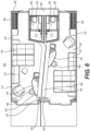
- FIG. 6 and FIG. 5 shows according to another aspect, the present embodiments may be a pair of cabins 600 comprising: a first cabin 602; a second cabin 604; wherein the first cabin 602 and the second cabin 604 are adjacent to each other and are defined by a first outer wall 610, a second outer wall 620, a third outer wall 630 and a fourth outer wall 640; the first outer wall 610, second outer wall 620, third outer wall 630 and fourth outer wall 640 defining a substantially rectangular area containing the first cabin 602 and the second cabin 604; wherein the first outer wall 610 meets the second outer wall 620 at a ninety (90) degree angle 615, the second outer wall 620 meets the third outer wall 630 at a ninety (90) degree angle 625, the third outer wall 630 meets the fourth outer wall 640 at a ninety (90) degree angle 635, and the fourth outer wall 640 meets the first outer wall 610 at a ninety (90) degree angle 615
- the present embodiments may further comprise a pair of cabins 600 wherein the first cabin 602, the second cabin 604, or both the first cabin 602 and second cabin 604 further comprise a desk 694, desk chair 696, and a closet 698 wherein heating, ventilation and air conditioning duct work 692 is positioned along the common wall 650.
- the approximating language may correspond to the precision of an instrument for measuring the value.
- Terms such as “first,” “second,” “upper,” “lower” etc. are used to identify one element from another, and unless otherwise specified are not meant to refer to a particular order or number of elements.
- the terms “may” and “may be” indicate a possibility of an occurrence within a set of circumstances; a possession of a specified property, characteristic or function; and/or qualify another verb by expressing one or more of an ability, capability, or possibility associated with the qualified verb. Accordingly, usage of “may” and “may be” indicates that a modified term is apparently appropriate, capable, or suitable for an indicated capacity, function, or usage, while taking into account that in some circumstances the modified term may sometimes not be appropriate, capable, or suitable. For example, in some circumstances an event or capacity can be expected, while in other circumstances the event or capacity cannot occur - this distinction is captured by the terms “may” and “may be.”
- the word "comprises” and its grammatical variants logically also subtend and include phrases of varying and differing extent such as for example, but not limited thereto, “consisting essentially of” and “consisting of.” Where necessary, ranges have been supplied, and those ranges are inclusive of all sub-ranges therebetween.
Landscapes
- Engineering & Computer Science (AREA)
- Ocean & Marine Engineering (AREA)
- Mechanical Engineering (AREA)
- Chemical & Material Sciences (AREA)
- Combustion & Propulsion (AREA)
- Architecture (AREA)
- Nursing (AREA)
- General Health & Medical Sciences (AREA)
- Health & Medical Sciences (AREA)
- Electromagnetism (AREA)
- Physics & Mathematics (AREA)
- Structural Engineering (AREA)
- Civil Engineering (AREA)
- Residential Or Office Buildings (AREA)
- Body Structure For Vehicles (AREA)
- Special Chairs (AREA)
- Tents Or Canopies (AREA)
Description
- In conventional cabin configurations, a cabin is fitted with a bed, a sofa, and other furnishings such as a desk, desk chair and other such related items.
- In order to minimize the space required for a cabin, while still allowing sufficient space for a user or users to circulate about the cabin, past methods for configuring the cabin utilized a method of placing a kink, or S offset, to a common wall between two adjacent cabins. The kink, or S offset, allows for the reallocation of some space along a portion of the common wall by making a cabin wider at one portion along the common wall (by taking space away from the adjacent cabin) while making the same cabin narrower along another portion of the common wall (by giving space to the adjacent cabin). The trading of space along the common wall by use of a kink, or S offset, allows larger objects, such as beds or sofas, to be positioned in a smaller cabin than would otherwise be possible without making the cabin feel cramped. However, this solution still has its limitations and can still result in a less than optimal use of space,
- Document
JP 2014 133519 A - Document
JP S61 211458 A - In view of the disadvantages associated with currently available methods and devices for a method of configuring a cabin, there is a need for a device and method that allows for improved use of space in a cabin by maximizing the number of users who can sleep in a cabin while minimizing the space required for the cabin to feel roomy enough for all occupants.
- According to an aspect, the present embodiments may be a pair of cabins comprising: a first cabin; a second cabin; wherein the first cabin and the second cabin are adjacent to each other and are defined by a first outer wall, a second outer wall, a third outer wall and a fourth outer wall; the first outer wall, second outer wall, third outer wall and fourth outer wall defining a substantially rectangular area containing the first cabin and the second cabin; wherein the first outer wall meets the second outer wall at a ninety (90) degree angle, the second outer wall meets the third outer wall at a ninety (90) degree angle, the third outer wall meets the fourth outer wall at a ninety (90) degree angle, and the fourth outer wall meets the first outer wall at a (90) degree angle; the first cabin and second cabin also sharing a common wall separating the first cabin from the second cabin; and wherein the common wall separating the first cabin from the second cabin is operatively connected to an outer wall at an angle other than ninety (90) degrees.
- According to another aspect, the present embodiments may further comprise a pair of cabins wherein the first cabin, or the second cabin, or both the first cabin and second cabin further comprise at least one L shaped sofa bed capable of being easily converted from a sofa to a bed and back again and dimensioned large enough to accommodate two (2) users when configured as a bed.
- According to another aspect, the present embodiments may further comprise a pair of cabins wherein the at least one L shaped sofa bed further comprises a stationary mattress on a plinth, a movable mattress on a plinth with drawers underneath, a movable armrest, and sofa back cushions capable of being easily converted from a sofa to a bed and back again.
- According to another aspect, the present embodiments may further comprise a pair of cabins wherein the at least one L shaped sofa bed is capable of being converted into a bed for two (2) users as well as capable of being converted into additional separate bed for one (1) additional user.
- According to another aspect, the present embodiments may further comprise a pair of cabins wherein the at least one L shaped sofa bed further comprises an additional mattress on a plinth with drawers underneath capable of being converted into a bed by unfolding the additional mattress, or rotating the additional mattress or both unfolding and rotating the additional mattress.
- According to another aspect, the present embodiments may further comprise a pair of cabins wherein the at least one L shaped sofa bed is positioned along the common wall.
- According to another aspect, the present embodiments may further comprise a pair of cabins, wherein the first cabin and the second cabin each further comprise a bathroom.
- According to another aspect, the present embodiments may further comprise a pair of cabins wherein the bathroom further comprises a firewall between the bathroom and a service space.
- According to another aspect, the present embodiments may further a pair of cabins wherein the first cabin, the second cabin, or both the first cabin and second cabin further comprise at least one interconnecting door on at least one outer wall.
- According to another aspect, the present embodiments may further comprise a pair of cabins wherein the first cabin, the second cabin, or both the first cabin and second cabin further comprise wherein heating, ventilation and air conditioning duct work is positioned along the common wall.
- According to another aspect, the present embodiments may further a pair of cabins wherein the first cabin, the second cabin, or both the first cabin and second cabin further comprise a desk and desk chair.
- According to another aspect, the present embodiments may further comprise a pair of cabins wherein the first cabin, the second cabin, or both the first cabin and second cabin further comprise a closet.
- According to another aspect, the present embodiments may be a method of creating a pair of cabins comprising: constructing a first outer wall, a second outer wall, a third outer wall and a fourth outer wall defining a substantially rectangular area containing a first cabin and a second cabin; wherein the first outer wall meets the second outer wall at a ninety (90) degree angle, the second outer wall meets the third outer wall at a ninety (90) degree angle, the third outer wall meets the fourth outer wall at a ninety (90) degree angle, and the fourth outer wall meets the first outer wall at a (90) degree angle; wherein a common wall separating the first cabin from the second cabin is constructed.
- According to another aspect, the present embodiments of the method may further comprise constructing a bathroom in each of the first cabin and the second cabin.
- According to another aspect, in the present embodiments of the method the bathroom may further comprise a firewall between the bathroom and a service space.
- A more particular description will be rendered by reference to specific embodiments thereof that are illustrated in the appended drawings. Understanding that these drawings depict only typical embodiments thereof and are not therefore to be considered to be limiting of its scope, exemplary embodiments will be described and explained with additional specificity and detail through the use of the accompanying drawings in which:
-
FIG. 1 is a perspective view of a double cabin featuring an angular wall according to an embodiment; -
FIG. 2 is a perspective view of a double cabin featuring an angular wall according to another embodiment; -
FIG. 3 is a top view of a double cabin featuring an angular wall according to another embodiment; -
FIG. 3 is an end view of the embodiment according toFIG. 1 ; -
FIG. 4 is a perspective view of an L shaped sofa bed for a double cabin featuring an angular wall configured in sofa mode according to an embodiment; -
FIG. 5 is a perspective view of an L shaped sofa bed for a double cabin featuring an angular wall configured in bed mode according to an embodiment; and -
FIG. 6 is a top view of a double cabin featuring an angular wall according to another embodiment. - Various features, aspects, and advantages of the embodiments will become more apparent from the following detailed description, along with the accompanying figures in which like numerals represent like components throughout the figures and text. The various described features are not necessarily drawn to scale, but are drawn to emphasize specific features relevant to some embodiments.
- Reference will now be made in detail to various embodiments. Each example is provided by way of explanation, and is not meant as a limitation and does not constitute a definition of all possible embodiments. The invention is set out in the appended set of claims.
- For purposes of illustrating features of the embodiments, a simple example will now be introduced and referenced throughout the disclosure. Those skilled in the art will recognize that this example is illustrative and not limiting and is provided purely for explanatory purposes. In the illustrative example and as seen in
FIG. 1 . -
FIG. 1 shows a pair ofcabins 100 comprising: afirst cabin 102; asecond cabin 104; wherein thefirst cabin 102 and thesecond cabin 104 are adjacent to each other and are defined by a firstouter wall 110, a secondouter wall 120, a thirdouter wall 130 and a fourthouter wall 140; the firstouter wall 110, secondouter wall 120, thirdouter wall 130 and fourthouter wall 140 defining a substantially rectangular area containing thefirst cabin 102 and thesecond cabin 104; wherein the firstouter wall 110 meets the secondouter wall 120 at a ninety (90)degree angle 115, the secondouter wall 120 meets the thirdouter wall 130 at a ninety (90)degree angle 125, the thirdouter wall 130 meets the fourthouter wall 140 at a ninety (90)degree angle 135, and the fourthouter wall 140 meets the firstouter wall 110 at a (90)degree angle 145; thefirst cabin 102 andsecond cabin 104 also sharing acommon wall 150 separating thefirst cabin 102 from thesecond cabin 104; and wherein thecommon wall 150 separating thefirst cabin 102 from thesecond cabin 104 is operatively connected to anouter wall degrees 155. - According to another aspect, the present embodiments may further comprise a pair of
cabins 100 wherein thefirst cabin 102, or thesecond cabin 104, or both thefirst cabin 102 andsecond cabin 104 further comprise at least one L shapedsofa bed 160 capable of being easily converted from a sofa to a bed and back again and dimensioned large enough to accommodate two (2) users when configured as a bed. - Turning now to
FIG. 4, FIG. 4 shows according to another aspect, the present embodiments may further comprise a pair of cabins wherein the at least one L shapedsofa bed 460 further comprises astationary mattress 461 on aplinth 462, amovable mattress 464 on aplinth 465 with drawers underneath 466, amovable armrest 467, andsofa back cushions 468 capable of being easily converted from a sofa to a bed and back again. - According to another aspect, the present embodiments may further comprise a pair of cabins wherein the at least one L
shaped sofa bed 460 is capable of being converted into a bed for two (2) users as well as capable of being converted into additionalseparate bed 470 for one (1) additional user. - According to another aspect, the present embodiments may further comprise a pair of cabins wherein the at least one L shaped
sofa bed 460 further comprises anadditional mattress 472 on aplinth 474 with drawers underneath 476 capable of being converted into a bed by unfolding theadditional mattress 472, or rotating theadditional mattress 472 or both unfolding and rotating theadditional mattress 472. - Turning now back to
FIG. 1, FIG. 1 shows according to another aspect, the present embodiments may further comprise a pair ofcabins 100 wherein the at least one L shapedsofa bed 160 is positioned along thecommon wall 150. - According to another aspect, the present embodiments may further comprise a pair of
cabins 100, wherein thefirst cabin 102 and thesecond cabin 104 each further comprise abathroom 180. - According to another aspect, the present embodiments may further comprise a pair of
cabins 100 wherein thebathroom 180 further comprises afirewall 182 between thebathroom 180 and aservice space 186. - According to another aspect, the present embodiments may further comprise a pair of
cabins 100 wherein thefirst cabin 102, thesecond cabin 104, or both thefirst cabin 102 andsecond cabin 104 further comprise at least one interconnectingdoor 190 on at least oneouter wall - According to another aspect, the present embodiments may further comprise a pair of
cabins 100 wherein thefirst cabin 102, thesecond cabin 104, or both thefirst cabin 102 andsecond cabin 104 further comprise wherein heating, ventilation and airconditioning duct work 192 is positioned along thecommon wall 150. - According to another aspect, the present embodiments may further comprise a pair of
cabins 100 wherein thefirst cabin 102, thesecond cabin 104, or both thefirst cabin 102 andsecond cabin 104 further comprise adesk 194 anddesk chair 196. - According to another aspect, the present embodiments may further comprise a pair of
cabins 100 wherein thefirst cabin 102, thesecond cabin 104, or both thefirst cabin 102 andsecond cabin 104 further comprise acloset 198. - Turning now to
FIG. 2 andFIG. 5 ,FIG. 2 andFIG. 5 show according to another aspect, the present embodiments may be a pair ofcabins 200 comprising: afirst cabin 202; asecond cabin 204; wherein thefirst cabin 202 and thesecond cabin 204 are adjacent to each other and are defined by a firstouter wall 210, a secondouter wall 220, a thirdouter wall 230 and a fourthouter wall 240; the firstouter wall 210, secondouter wall 220, thirdouter wall 230 and fourthouter wall 240 defining a substantially rectangular area containing thefirst cabin 202 and thesecond cabin 204; wherein the firstouter wall 210 meets the second outer 220 wall at a ninety (90)degree angle 215, the second outer 220 wall meets the thirdouter wall 230 at a ninety (90)degree angle 225, the thirdouter wall 230 meets the fourthouter wall 240 at a ninety (90)degree angle 235, and the fourthouter wall 240 meets the firstouter wall 210 at a (90)degree angle 245; the first cabin and second cabin also sharing acommon wall 250 separating thefirst cabin 202 from thesecond cabin 204; wherein thecommon wall 250 separating thefirst cabin 202 from thesecond cabin 204 is operatively connected to anouter wall degrees 255; wherein thefirst cabin 202, or thesecond cabin 204, or both thefirst cabin 202 andsecond cabin 204 further comprise at least one L shapedsofa bed 260 capable of being easily converted from a sofa to a bed and back again and dimensioned large enough to accommodate two (2) users when configured as a bed; and wherein the at least one L shapedsofa bed 260 further comprises astationary mattress 561 on a plinth (not shown), amovable mattress 564 on aplinth 565 withdrawers 566 underneath, amovable armrest 567, andsofa back cushions 568 capable of being easily converted from a sofa to a bed and back again. - Turning now to
FIG. 5, FIG. 5 shows according to another aspect, the present embodiments may further comprise a pair of cabins wherein the at least one L shapedsofa bed 560 is capable of being converted into a bed for two (2) users as well as capable of being converted into additionalseparate bed 570 for one (1) additional user. - According to another aspect, the present embodiments may further comprise a pair of cabins wherein the at least one L shaped
sofa bed 560 further comprises anadditional mattress 572 on aplinth 574 with drawers underneath 576 capable of being converted into a bed by unfolding theadditional mattress 572, or rotating theadditional mattress 572 or both unfolding and rotating theadditional mattress 572. - Turning back to
FIG. 2, FIG. 2 shows according to another aspect, the present embodiments may further comprise a pair ofcabins 200 wherein the at least one L shapedsofa bed 260 is positioned along thecommon wall 250. - According to another aspect, the present embodiments may further comprise a pair of
cabins 200 wherein thefirst cabin 202 and thesecond cabin 204 each further comprise abathroom 280. - According to another aspect, the present embodiments may further comprise a pair of
cabins 200 wherein thebathroom 280 further comprises afirewall 282 between thebathroom 280 and aservice space 286. - According to another aspect, the present embodiments may further comprise a pair of
cabins 200 wherein thefirst cabin 202, thesecond cabin 204, or both thefirst cabin 202 andsecond cabin 204 further comprise at least one interconnectingdoor 290 on at least oneouter wall - In another aspect, the present embodiments may further comprise a pair of
cabins 200 wherein thefirst cabin 202, thesecond cabin 204, or both thefirst cabin 202 andsecond cabin 204 further comprise adesk 294,desk chair 296, and acloset 298 wherein heating, ventilation and airconditioning duct work 292 is positioned along thecommon wall 250. - Turning now to
FIG. 3 andFIG. 5 ,FIG. 3 andFIG. 5 shows according to another aspect, the present embodiments may be a pair of cabins 300 comprising: a first cabin 302; a second cabin 304; wherein the first cabin 302 and the second cabin 304 are adjacent to each other and are defined by a first outer wall 310, a second outer wall 320, a third outer wall 330 and a fourth outer wall 340; the first outer wall 310, second outer wall 320, third outer wall 330 and fourth outer wall 340 defining a substantially rectangular area containing the first cabin 302 and the second cabin 304; wherein the first outer wall 310 meets the second outer wall 320 at a ninety (90) degree angle 315, the second outer wall 320 meets the third outer wall 330 at a ninety (90) degree angle 325, the third outer wall 330 meets the fourth outer wall 340 at a ninety (90) degree angle 335, and the fourth outer wall 340 meets the first outer wall 310 at a (90) degree angle 345; the first cabin 302 and second cabin 304 also sharing a common wall 350 separating the first cabin 302 from the second cabin 304; wherein the common wall 350 separating the first cabin 302 from the second cabin 304 is operatively connected to an outer wall 310, 320, 330 or 340 at an angle other than ninety (90) degrees 355; wherein the first cabin 302, or the second cabin 304, or both the first cabin 302 and second cabin 304 further comprise at least one L shaped sofa bed 360 capable of being easily converted from a sofa to a bed and back again and dimensioned large enough to accommodate two (2) users when configured as a bed; and wherein the at least one L shaped sofa bed 360 further comprises a stationary mattress 561 on a plinth (not shown), a movable mattress 564 on a plinth 565 with drawers underneath 566, a movable armrest 567, and sofa back cushions 568 capable of being easily converted from a sofa to a bed and back again; wherein the at least one L shaped sofa bed 560 is positioned along the common wall 350; wherein the first cabin 302 and the second cabin 304 each further comprise a bathroom 380; wherein the bathroom further comprises a firewall 382 between the bathroom 384 and a service space 386; and wherein the first cabin 302, the second cabin 304, or both the first cabin 302 and second cabin 304 further comprise at least one interconnecting door (not shown) on at least one outer wall 310, 320, 330, or 340. - In another aspect, the present embodiments may further comprise a pair of
cabins 300 wherein thefirst cabin 302, thesecond cabin 304, or both thefirst cabin 302 andsecond cabin 304 further comprise adesk 394,desk chair 396, and acloset 398 wherein heating, ventilation and airconditioning duct work 392 is positioned along thecommon wall 350. - Turning now to
FIG. 6 andFig. 5 ,FIG. 6 andFIG. 5 shows according to another aspect, the present embodiments may be a pair of cabins 600 comprising: a first cabin 602; a second cabin 604; wherein the first cabin 602 and the second cabin 604 are adjacent to each other and are defined by a first outer wall 610, a second outer wall 620, a third outer wall 630 and a fourth outer wall 640; the first outer wall 610, second outer wall 620, third outer wall 630 and fourth outer wall 640 defining a substantially rectangular area containing the first cabin 602 and the second cabin 604; wherein the first outer wall 610 meets the second outer wall 620 at a ninety (90) degree angle 615, the second outer wall 620 meets the third outer wall 630 at a ninety (90) degree angle 625, the third outer wall 630 meets the fourth outer wall 640 at a ninety (90) degree angle 635, and the fourth outer wall 640 meets the first outer wall 610 at a (90) degree angle 645; the first cabin 602 and second cabin 604 also sharing a common wall 650 separating the first cabin 602 from the second cabin 604; wherein the common wall 650 separating the first cabin 602 from the second cabin 604 is operatively connected to an outer wall 610, 620, 630 or 640 at an angle other than ninety (90) degrees 655; wherein the first cabin 602, or the second cabin 604, or both the first cabin 602 and second cabin 604 further comprise at least one L shaped sofa bed 660 capable of being easily converted from a sofa to a bed and back again and dimensioned large enough to accommodate two (2) users when configured as a bed; and wherein the at least one L shaped sofa bed 660 further comprises a stationary mattress 561 on a plinth (not shown), a movable mattress 564 on a plinth 565 with drawers underneath 566, a movable armrest 567, and sofa back cushions 568 capable of being easily converted from a sofa to a bed and back again; wherein the at least one L shaped sofa bed 560 is positioned along the common wall 650; wherein the first cabin 602 and the second cabin 604 each further comprise a bathroom 680; wherein the bathroom further comprises a firewall 682 between the bathroom 684 and a service space 686; and wherein the first cabin 602, the second cabin 604, or both the first cabin 602 and second cabin 604 further comprise at least one interconnecting door (not shown) on at least one outer wall 610, 620, 630, or 640. - In another aspect, the present embodiments may further comprise a pair of
cabins 600 wherein thefirst cabin 602, thesecond cabin 604, or both thefirst cabin 602 andsecond cabin 604 further comprise adesk 694,desk chair 696, and acloset 698 wherein heating, ventilation and airconditioning duct work 692 is positioned along thecommon wall 650. - The components of the apparatus illustrated are not limited to the specific embodiments described herein, but rather, features illustrated or described as part of one embodiment can be used on or in conjunction with other embodiments to yield yet a further embodiment. It is intended that the apparatus include such modifications and variations. Further, steps described in the method may be utilized independently and separately from other steps described herein.
- In this specification and the claims that follow, reference will be made to a number of terms that have the following meanings. The singular forms "a," "an" and "the" include plural referents unless the context clearly dictates otherwise. Furthermore, references to "one embodiment", "some embodiments", "an embodiment" and the like are not intended to be interpreted as excluding the existence of additional embodiments that also incorporate the recited features. Approximating language, as used herein throughout the specification and claims, may be applied to modify any quantitative representation that could permissibly vary without resulting in a change in the basic function to which it is related. Accordingly, a value modified by a term such as "about" is not to be limited to the precise value specified. In some instances, the approximating language may correspond to the precision of an instrument for measuring the value. Terms such as "first," "second," "upper," "lower" etc. are used to identify one element from another, and unless otherwise specified are not meant to refer to a particular order or number of elements.
- As used herein, the terms "may" and "may be" indicate a possibility of an occurrence within a set of circumstances; a possession of a specified property, characteristic or function; and/or qualify another verb by expressing one or more of an ability, capability, or possibility associated with the qualified verb. Accordingly, usage of "may" and "may be" indicates that a modified term is apparently appropriate, capable, or suitable for an indicated capacity, function, or usage, while taking into account that in some circumstances the modified term may sometimes not be appropriate, capable, or suitable. For example, in some circumstances an event or capacity can be expected, while in other circumstances the event or capacity cannot occur - this distinction is captured by the terms "may" and "may be."
- As used in the claims, the word "comprises" and its grammatical variants logically also subtend and include phrases of varying and differing extent such as for example, but not limited thereto, "consisting essentially of" and "consisting of." Where necessary, ranges have been supplied, and those ranges are inclusive of all sub-ranges therebetween.
- Advances in science and technology may make equivalents and substitutions possible that are not now contemplated by reason of the imprecision of language; these variations should be covered by the appended claims. This written description uses examples to disclose the method and pair of cabins, including the best mode, and also to enable any person of ordinary skill in the art to practice these, including making and using any devices or systems and performing any incorporated methods. The patentable scope thereof is defined by the claims, and may include other examples that occur to those of ordinary skill in the art. Such other examples are intended to be within the scope of the claims if they have structural elements that do not differ from the literal language of the claims, or if they include equivalent structural elements with insubstantial differences from the literal language of the claims.
Claims (15)
- A pair of cabins (100) comprising:a first cabin (102);a second cabin (104);wherein the first cabin (102) and the second cabin (104) are adjacent to each other and are defined by a first outer wall (110), a second outer wall (120), a third outer wall (130) and a fourth outer wall (140);the first outer wall (110), second outer wall (120), third outer wall (130) and fourth outer wall (140) defining a substantially rectangular area containing the first cabin (102) and the second cabin (104);wherein the first outer wall (110) meets the second outer wall (120) at a ninety degree angle (115), the second outer wall (120) meets the third outer wall (130) at a ninety degree angle (125), the third outer wall (130) meets the fourth outer wall (140) at a ninety degree angle (135), and the fourth outer wall (140) meets the first outer wall (110) at a ninety degree angle (145);wherein the first cabin (102) and second cabin (104) are also sharing a common wall (150) separating the first cabin (102) from the second cabin (104); andwherein the common wall (150) separating the first cabin (102) from the second cabin (104) is operatively connected to the first outer wall (110), the second outer wall (120), the third outer wall (130), or the fourth outer wall (140) at an angle other than ninety degrees (155).
- The pair of cabins (100) of claim 1, wherein the first cabin (102), or the second cabin (104), or both the first cabin (102) and second cabin (104) further comprise at least one L shaped sofa bed (160) capable of being easily converted from a sofa to a bed and back again and dimensioned large enough to accommodate two users when configured as a bed.
- The pair of cabins (100) of claim 2, wherein the at least one L shaped sofa bed (160) further comprises a stationary mattress (461) on a plinth (462), a movable mattress (464) on a plinth (465) with drawers (466) underneath, a movable armrest (467), and sofa back cushions (468) capable of being easily converted from a sofa to a bed and back again.
- The pair of cabins (100) of claim 3, wherein the at least one L shaped sofa bed (160) is capable of being converted into a bed for two users as well as capable of being converted into an additional separate bed (470) for one additional user.
- The pair of cabins (100) of claim 4, wherein the at least one L shaped sofa bed (160) further comprises an additional mattress (472) on a plinth (474) with drawers (476) underneath capable of being converted into a bed by unfolding the additional mattress (472), or rotating the additional mattress (472) or both unfolding and rotating the additional mattress (472).
- The pair of cabins (100) of claim 2, wherein the at least one L shaped sofa bed (160) is positioned along the common wall (150).
- The pair of cabins (100) of claim 1, wherein the first cabin (102) and the second cabin (104) each further comprise a bathroom (180).
- The pair of cabins (100) of claim 7, wherein the bathroom (180) further comprises a firewall (182) between the bathroom (180) and a service space (186).
- The pair of cabins (100) of claim 1, wherein the first cabin (102), the second cabin (104), or both the first cabin (102) and second cabin (104) further comprise at least one interconnecting door (190) on at least one outer wall (110, 120, 130, 140).
- The pair of cabins (100) of claim 1, wherein the first cabin (102), the second cabin (104), or both the first cabin (102) and second cabin (104) further comprise heating, ventilation and air conditioning duct work (192) positioned along the common wall (150).
- The pair of cabins (100) of claim 1, wherein the first cabin (102), the second cabin (104), or both the first cabin (102) and second cabin (104) further comprise a desk (194) and desk chair (196).
- The pair of cabins (100) of claim 1, wherein the first cabin (102), the second cabin (104), or both the first cabin (102) and second cabin (104) further comprise a closet (198).
- A method of creating a pair of cabins (100) comprising:constructing a first outer wall (110), second outer wall (120), third outer wall (130) and fourth outer wall (140) defining a substantially rectangular area containing a first cabin (102) and a second cabin (104) adjacent to each other;wherein the first outer wall (110) meets the second outer wall (120) at a ninety degree angle (115), the second outer wall (120) meets the third outer wall (130) at a ninety degree angle (125), the third outer wall (130) meets the fourth outer wall (140) at a ninety degree angle (135), and the fourth outer wall (140) meets the first outer wall (110) at a ninety degree angle (145);characterized in that a common wall (150) separating the first cabin (102) from the second cabin (104) is constructed, andthat the common wall (150) separating the first cabin (102) from the second cabin (104) is operatively connected to the first outer wall (110), the second outer wall (120), the third outer wall (130), or the fourth outer wall (140) at an angle other than ninety degrees (155).
- The method of creating a pair of cabins (100) of claim 13, further comprising constructing a bathroom (180) in each of the first cabin (102) and the second cabin (104).
- The method of creating a pair of cabins (100) of claim 14, wherein the bathroom (180) further comprises a firewall (182) between the bathroom (180) and a service space (186).
Priority Applications (1)
| Application Number | Priority Date | Filing Date | Title |
|---|---|---|---|
| HRP20250546TT HRP20250546T1 (en) | 2017-10-31 | 2018-10-24 | DOUBLE CABIN WITH CORNER WALL |
Applications Claiming Priority (2)
| Application Number | Priority Date | Filing Date | Title |
|---|---|---|---|
| US15/799,693 US11674301B2 (en) | 2017-10-31 | 2017-10-31 | Double-cabin featuring an angular wall |
| PCT/US2018/057283 WO2019089320A1 (en) | 2017-10-31 | 2018-10-24 | Double-cabin featuring an angular wall |
Publications (4)
| Publication Number | Publication Date |
|---|---|
| EP3704321A1 EP3704321A1 (en) | 2020-09-09 |
| EP3704321A4 EP3704321A4 (en) | 2021-08-04 |
| EP3704321C0 EP3704321C0 (en) | 2025-03-12 |
| EP3704321B1 true EP3704321B1 (en) | 2025-03-12 |
Family
ID=66332281
Family Applications (1)
| Application Number | Title | Priority Date | Filing Date |
|---|---|---|---|
| EP18873204.4A Active EP3704321B1 (en) | 2017-10-31 | 2018-10-24 | Double-cabin featuring an angular wall |
Country Status (6)
| Country | Link |
|---|---|
| US (1) | US11674301B2 (en) |
| EP (1) | EP3704321B1 (en) |
| CN (1) | CN111448357A (en) |
| ES (1) | ES3024858T3 (en) |
| HR (1) | HRP20250546T1 (en) |
| WO (1) | WO2019089320A1 (en) |
Families Citing this family (15)
| Publication number | Priority date | Publication date | Assignee | Title |
|---|---|---|---|---|
| USD910331S1 (en) * | 2017-10-31 | 2021-02-16 | Virgin Cruises Intermediate Limited | Sofa bed for cruise ship |
| US12251025B2 (en) * | 2018-12-20 | 2025-03-18 | Smart Bunks IP Pty Ltd. | Modular bunk |
| WO2021074690A1 (en) * | 2019-10-17 | 2021-04-22 | Style & Design Group | Individual aircraft passenger arrangement with separate seat and bed |
| CN110789691A (en) * | 2019-11-10 | 2020-02-14 | 荆门一天阁动力机械科技有限责任公司 | Rescue cabin for ship |
| US12351028B1 (en) | 2021-08-13 | 2025-07-08 | Oshkosh Defense, Llc | Military vehicle with modular battery units |
| US12319160B1 (en) | 2021-08-13 | 2025-06-03 | Oshkosh Defense, Llc | Convoy operations for electrified military vehicles |
| US12358361B1 (en) | 2021-08-13 | 2025-07-15 | Oshkosh Defense, Llc | Electrified military vehicle with electric weaponry support system |
| US12311754B1 (en) | 2021-08-13 | 2025-05-27 | Oshkosh Defense, Llc | Power export system for a military vehicle |
| US12030479B1 (en) | 2021-08-13 | 2024-07-09 | Oshkosh Defense, Llc | Prioritized charging of an energy storage system of a military vehicle |
| US12130122B1 (en) | 2021-08-13 | 2024-10-29 | Oshkosh Defense, Llc | Military vehicle with battery armor |
| US12583309B1 (en) | 2021-08-13 | 2026-03-24 | Oshkosh Defense, Llc | Hybrid power system for a military vehicle |
| US12060053B1 (en) | 2021-08-13 | 2024-08-13 | Oshkosh Defense, Llc | Military vehicle with control modes |
| US12083995B1 (en) | 2021-08-13 | 2024-09-10 | Oshkosh Defense, Llc | Power export system for a military vehicle |
| US11608050B1 (en) | 2021-08-13 | 2023-03-21 | Oshkosh Defense, Llc | Electrified military vehicle |
| WO2024095951A1 (en) * | 2022-10-31 | 2024-05-10 | 国立研究開発法人量子科学技術研究開発機構 | Radionuclide-containing substance administration facility unit |
Family Cites Families (59)
| Publication number | Priority date | Publication date | Assignee | Title |
|---|---|---|---|---|
| GB598859A (en) | 1945-09-21 | 1948-02-27 | Ralph Marshall | Improvements in or relating to railway carriages, ships, road-vehicles, aeroplanes and caravans having sleeping compartments or cabins |
| US1464189A (en) * | 1921-09-08 | 1923-08-07 | Simonson B Hustace | Building construction |
| GB313382A (en) | 1928-09-20 | 1929-06-13 | George Gillies Sharp | Improvements in passenger ship construction |
| US2247340A (en) * | 1938-04-14 | 1941-06-24 | John E Webster | Auxiliary building structure |
| US2625714A (en) * | 1948-07-06 | 1953-01-20 | Clark Harry Stanley | Functional type house |
| US3002233A (en) * | 1959-02-06 | 1961-10-03 | Hellmuth Obata & Kassabaum Inc | Auditorium structures |
| US3058123A (en) * | 1959-11-16 | 1962-10-16 | Englander Co Inc | Convertible corner bed ensemble |
| BE607711A (en) * | 1960-09-14 | 1961-12-18 | Patent Concern Nv | Building with at least one floor |
| US3059246A (en) * | 1960-11-07 | 1962-10-23 | Shlaes Jacquelyn | Combination sofa-bed and table structure |
| US3106724A (en) * | 1960-12-27 | 1963-10-15 | Englander Co Inc | Corner bed structure |
| US3084351A (en) * | 1961-03-13 | 1963-04-09 | Oxford Ltd | Combined bed and lounge |
| US3623285A (en) | 1969-09-26 | 1971-11-30 | C Electronics Inc Sa | Building construction module |
| US3852924A (en) * | 1971-01-08 | 1974-12-10 | N Levenson | Housing assembly with convertible housing units |
| US3952465A (en) | 1971-03-19 | 1976-04-27 | Dominic Joseph Masiello | Building structure formed of modular units with cantilevered portions for forming a corridor floor |
| US4000589A (en) * | 1976-02-13 | 1977-01-04 | Antonio Bianchini | Congruent modular building segments |
| US4198791A (en) | 1976-04-28 | 1980-04-22 | Methodios Kalkaslief | Standard modules for architectonic compositions |
| US4325205A (en) * | 1980-03-31 | 1982-04-20 | Tios Corporation | Modular solar building construction |
| US4321717A (en) * | 1980-07-11 | 1982-03-30 | Luis F. Segarra Boerman | Sofa bed |
| FI62984C (en) | 1980-10-24 | 1987-02-17 | Waertsilae Oy Ab | Cabin element system in ships. |
| US4513545A (en) * | 1982-09-20 | 1985-04-30 | Hopkins Jr George D | Apparatus for and method of constructing, transporting and erecting a structure of two or more stories comprised of a plurality of prefabricated core modules and panelized room elements |
| JPS61211458A (en) | 1985-03-15 | 1986-09-19 | 日本鋼管株式会社 | Sitting room structure |
| FI78036C (en) * | 1987-05-27 | 1989-06-12 | Waertsilae Meriteollisuus | ANORDNING FOER HYTTELEMENT. |
| US4920711A (en) * | 1988-11-14 | 1990-05-01 | Mitchell Sr Richard F | Building construction system |
| US4942706A (en) * | 1989-11-13 | 1990-07-24 | Todd Wayne A | Housing structure |
| DE4005902A1 (en) | 1990-02-24 | 1991-08-29 | Walter Loidl | Space-saving toilet and wash room construction - involves doors fitted at approximate angle of 45 deg. |
| JP2533987Y2 (en) | 1991-05-14 | 1997-04-30 | 石川島播磨重工業株式会社 | Fire protection structure in hull settlement |
| JP3137478B2 (en) | 1992-12-22 | 2001-02-19 | 株式会社テラテック | Electron wave interference device |
| US20100043339A1 (en) * | 1995-04-27 | 2010-02-25 | Dirk Van Dijk | Modular Housing Unit |
| US5575120A (en) * | 1995-06-06 | 1996-11-19 | Handley; Frederick G. | Design and construction module |
| US5906075A (en) * | 1997-02-06 | 1999-05-25 | Sowers; John Mark | Modular building structure |
| US6164018A (en) * | 1997-12-08 | 2000-12-26 | Shopro, Inc. | Cinematic theater and theater multiplex |
| US6035585A (en) * | 1998-04-06 | 2000-03-14 | Boyd; Jon Taylor | Apparatus and method for a portable, modular, vehicle washing and servicing structure |
| US6016636A (en) | 1998-06-04 | 2000-01-25 | Hopeman Brothers Marine Interiors Llc | Modular ship's cabin and method of installation |
| FR2783493B1 (en) | 1998-09-18 | 2000-12-15 | Alstom Technology | METHOD FOR MOUNTING PARTITION PANELS ON SHIP CABINS AND MANNEQUIN SUPPORT FOR IMPLEMENTING THE METHOD |
| US6826879B1 (en) * | 1999-02-19 | 2004-12-07 | Cathartes Investment | Modular building construction |
| US6256936B1 (en) * | 1999-03-11 | 2001-07-10 | Wellness, Llc | Vanity station and nurse's station |
| US6243993B1 (en) | 1999-03-11 | 2001-06-12 | Wellness, Llc | Modular healthcare room interior |
| US20090031642A1 (en) * | 1999-03-23 | 2009-02-05 | Embleton Limited | Interactive building module |
| US6494013B2 (en) * | 2001-01-20 | 2002-12-17 | Richard W. Winskye | Building construction system, components thereof, and method therefore |
| SE0201899L (en) * | 2002-06-18 | 2003-05-20 | Bernt Nord | Building for a group housing facility |
| FR2842497B1 (en) | 2002-07-19 | 2004-10-01 | Airbus | AIRCRAFT CABIN MODULE FOR PASSENGERS |
| FI20022243A0 (en) | 2002-12-20 | 2002-12-20 | Piikkioe Works Oy | Method and arrangement for modifying a room unit to be installed on a ship |
| DE20318195U1 (en) | 2003-11-25 | 2004-04-22 | Meyer, Hans Dieter | Room divider has a walk in cupboard and an angled wall fitted with a bed frame with rounded outer corners |
| US7418803B2 (en) * | 2004-04-05 | 2008-09-02 | Jenkins William O | Self-contained modular home |
| ITPD20060037A1 (en) | 2006-02-03 | 2007-08-04 | Ct Per Gli Studi Di Tecnica Navale Spa | PASSENGER SHIP IN PARTICULAR FROM CRUISE AND ASSEMBLY CABINS FOR PASSENGER SHIP |
| CN201709860U (en) * | 2010-06-13 | 2011-01-19 | 马波 | Novel multifunctional sofa |
| US8499504B1 (en) * | 2012-08-07 | 2013-08-06 | Dennis Sherbakov | Prefabricated building and method for constructing a building |
| EP3405638B1 (en) * | 2012-09-04 | 2022-08-17 | Amazon Technologies, Inc. | Expandable data center with movable wall |
| US20140096461A1 (en) | 2012-10-08 | 2014-04-10 | Six Continents Hotels, Inc. | Hotel rooms |
| JP2014133519A (en) | 2013-01-11 | 2014-07-24 | Mitsubishi Heavy Ind Ltd | Unit cabin and installation method thereof |
| JP2015009638A (en) | 2013-06-27 | 2015-01-19 | 三菱重工業株式会社 | Habitable room structure of vessel |
| CN203393869U (en) | 2013-08-06 | 2014-01-15 | 临海市第四建筑工程公司 | Movable partition wall |
| US9194143B2 (en) * | 2013-08-23 | 2015-11-24 | Six Continents Hotels, Inc. | Business productivity room |
| CN203693016U (en) | 2013-11-13 | 2014-07-09 | 何江科 | L-shaped corner leisure sofa bed with bed assembly |
| WO2015150843A2 (en) * | 2014-04-01 | 2015-10-08 | Noah House Kft. | Mobile house utilising renewable energy |
| US20150308136A1 (en) | 2014-04-23 | 2015-10-29 | Six Continents Hotels, Inc. | Hotel room acoustic door |
| SG11201700155YA (en) * | 2014-07-11 | 2017-02-27 | G Con Mfg Inc | Modular parts that supply utilities to cleanroom, isolation or containment cubicles, pods, or modules |
| US9695608B2 (en) * | 2015-07-01 | 2017-07-04 | District Homes, LLC | Reconfigurable residential unit |
| CN205234025U (en) * | 2015-12-03 | 2016-05-18 | 德阳凯达门业有限公司 | Simply make up multi -functional sofa bed |
-
2017
- 2017-10-31 US US15/799,693 patent/US11674301B2/en active Active
-
2018
- 2018-10-24 WO PCT/US2018/057283 patent/WO2019089320A1/en not_active Ceased
- 2018-10-24 EP EP18873204.4A patent/EP3704321B1/en active Active
- 2018-10-24 CN CN201880071068.5A patent/CN111448357A/en active Pending
- 2018-10-24 ES ES18873204T patent/ES3024858T3/en active Active
- 2018-10-24 HR HRP20250546TT patent/HRP20250546T1/en unknown
Also Published As
| Publication number | Publication date |
|---|---|
| US11674301B2 (en) | 2023-06-13 |
| US20200385977A1 (en) | 2020-12-10 |
| EP3704321C0 (en) | 2025-03-12 |
| EP3704321A1 (en) | 2020-09-09 |
| ES3024858T3 (en) | 2025-06-05 |
| EP3704321A4 (en) | 2021-08-04 |
| WO2019089320A1 (en) | 2019-05-09 |
| CN111448357A (en) | 2020-07-24 |
| HRP20250546T1 (en) | 2025-06-20 |
Similar Documents
| Publication | Publication Date | Title |
|---|---|---|
| US11674301B2 (en) | Double-cabin featuring an angular wall | |
| AU2013234431B2 (en) | Hotel rooms | |
| US20210378423A1 (en) | Bed sheet assembly | |
| US10034550B2 (en) | Sound dampening device | |
| GB2400242B (en) | Under floor remote seat cluster and integrated housing system for aircraft passenger entertainment systems and the like | |
| US20160076266A1 (en) | Business productivity room | |
| EP2787136B1 (en) | Integrated dialysis unit module | |
| DE102012101642A1 (en) | Suction machine with housing made of expanded plastic | |
| US20220125207A1 (en) | Retrofitting apparatus for a chair that extends around sides of an upper body portion of a user seated in the chair | |
| JP4319558B2 (en) | Partition device | |
| US20240197092A1 (en) | Face pillow with inside air channel | |
| KR101436209B1 (en) | individual Arrival-type Rest Room for being Composed of a Multilayer | |
| DE202009012691U1 (en) | Inflatable auxiliary belt device and supporting auxiliary device | |
| CN106175246A (en) | A kind of folding bed | |
| DE19954483B4 (en) | Speaker Pillow | |
| Williams | A Two-Office Approach to Eliminating Clutter | |
| EP2174831A2 (en) | Road vehicle | |
| US20230230507A1 (en) | Apparatus and method for visualizing a room layout | |
| JP3124759U (en) | Hotel structure with room for disabled people | |
| CN205875790U (en) | Reduce noise's meeting room | |
| JPH08338140A (en) | Nursing home | |
| Ehrenberg et al. | SENSE-SEAT: challenging disruptions in shared workspaces through a sensor-based SEAT | |
| KR100599401B1 (en) | Two sets of interlocking folding beds for submarine | |
| CN202828016U (en) | Guest room provided with partition curtain and used for vessel | |
| CN204520000U (en) | A kind of combined mattress |
Legal Events
| Date | Code | Title | Description |
|---|---|---|---|
| REG | Reference to a national code |
Ref country code: HR Ref legal event code: TUEP Ref document number: P20250546T Country of ref document: HR |
|
| STAA | Information on the status of an ep patent application or granted ep patent |
Free format text: STATUS: THE INTERNATIONAL PUBLICATION HAS BEEN MADE |
|
| PUAI | Public reference made under article 153(3) epc to a published international application that has entered the european phase |
Free format text: ORIGINAL CODE: 0009012 |
|
| STAA | Information on the status of an ep patent application or granted ep patent |
Free format text: STATUS: REQUEST FOR EXAMINATION WAS MADE |
|
| 17P | Request for examination filed |
Effective date: 20200527 |
|
| AK | Designated contracting states |
Kind code of ref document: A1 Designated state(s): AL AT BE BG CH CY CZ DE DK EE ES FI FR GB GR HR HU IE IS IT LI LT LU LV MC MK MT NL NO PL PT RO RS SE SI SK SM TR |
|
| AX | Request for extension of the european patent |
Extension state: BA ME |
|
| DAV | Request for validation of the european patent (deleted) | ||
| DAX | Request for extension of the european patent (deleted) | ||
| A4 | Supplementary search report drawn up and despatched |
Effective date: 20210707 |
|
| RIC1 | Information provided on ipc code assigned before grant |
Ipc: E04B 1/348 20060101AFI20210701BHEP Ipc: E04H 1/02 20060101ALI20210701BHEP Ipc: B61D 1/08 20060101ALI20210701BHEP Ipc: B63B 29/02 20060101ALI20210701BHEP |
|
| STAA | Information on the status of an ep patent application or granted ep patent |
Free format text: STATUS: EXAMINATION IS IN PROGRESS |
|
| 17Q | First examination report despatched |
Effective date: 20230627 |
|
| GRAP | Despatch of communication of intention to grant a patent |
Free format text: ORIGINAL CODE: EPIDOSNIGR1 |
|
| STAA | Information on the status of an ep patent application or granted ep patent |
Free format text: STATUS: GRANT OF PATENT IS INTENDED |
|
| INTG | Intention to grant announced |
Effective date: 20241004 |
|
| GRAS | Grant fee paid |
Free format text: ORIGINAL CODE: EPIDOSNIGR3 |
|
| GRAA | (expected) grant |
Free format text: ORIGINAL CODE: 0009210 |
|
| STAA | Information on the status of an ep patent application or granted ep patent |
Free format text: STATUS: THE PATENT HAS BEEN GRANTED |
|
| AK | Designated contracting states |
Kind code of ref document: B1 Designated state(s): AL AT BE BG CH CY CZ DE DK EE ES FI FR GB GR HR HU IE IS IT LI LT LU LV MC MK MT NL NO PL PT RO RS SE SI SK SM TR |
|
| REG | Reference to a national code |
Ref country code: GB Ref legal event code: FG4D |
|
| REG | Reference to a national code |
Ref country code: CH Ref legal event code: EP |
|
| REG | Reference to a national code |
Ref country code: DE Ref legal event code: R096 Ref document number: 602018080130 Country of ref document: DE |
|
| REG | Reference to a national code |
Ref country code: IE Ref legal event code: FG4D |
|
| U01 | Request for unitary effect filed |
Effective date: 20250410 |
|
| U07 | Unitary effect registered |
Designated state(s): AT BE BG DE DK EE FI FR IT LT LU LV MT NL PT RO SE SI Effective date: 20250416 |
|
| REG | Reference to a national code |
Ref country code: ES Ref legal event code: FG2A Ref document number: 3024858 Country of ref document: ES Kind code of ref document: T3 Effective date: 20250605 |
|
| REG | Reference to a national code |
Ref country code: HR Ref legal event code: T1PR Ref document number: P20250546 Country of ref document: HR |
|
| PG25 | Lapsed in a contracting state [announced via postgrant information from national office to epo] |
Ref country code: RS Free format text: LAPSE BECAUSE OF FAILURE TO SUBMIT A TRANSLATION OF THE DESCRIPTION OR TO PAY THE FEE WITHIN THE PRESCRIBED TIME-LIMIT Effective date: 20250612 |
|
| REG | Reference to a national code |
Ref country code: GR Ref legal event code: EP Ref document number: 20250400984 Country of ref document: GR Effective date: 20250613 |
|
| PG25 | Lapsed in a contracting state [announced via postgrant information from national office to epo] |
Ref country code: SM Free format text: LAPSE BECAUSE OF FAILURE TO SUBMIT A TRANSLATION OF THE DESCRIPTION OR TO PAY THE FEE WITHIN THE PRESCRIBED TIME-LIMIT Effective date: 20250312 |
|
| PG25 | Lapsed in a contracting state [announced via postgrant information from national office to epo] |
Ref country code: PL Free format text: LAPSE BECAUSE OF FAILURE TO SUBMIT A TRANSLATION OF THE DESCRIPTION OR TO PAY THE FEE WITHIN THE PRESCRIBED TIME-LIMIT Effective date: 20250312 |
|
| PG25 | Lapsed in a contracting state [announced via postgrant information from national office to epo] |
Ref country code: CZ Free format text: LAPSE BECAUSE OF FAILURE TO SUBMIT A TRANSLATION OF THE DESCRIPTION OR TO PAY THE FEE WITHIN THE PRESCRIBED TIME-LIMIT Effective date: 20250312 |
|
| PG25 | Lapsed in a contracting state [announced via postgrant information from national office to epo] |
Ref country code: SK Free format text: LAPSE BECAUSE OF FAILURE TO SUBMIT A TRANSLATION OF THE DESCRIPTION OR TO PAY THE FEE WITHIN THE PRESCRIBED TIME-LIMIT Effective date: 20250312 |
|
| U20 | Renewal fee for the european patent with unitary effect paid |
Year of fee payment: 8 Effective date: 20251030 |
|
| REG | Reference to a national code |
Ref country code: HR Ref legal event code: ODRP Ref document number: P20250546 Country of ref document: HR Payment date: 20251114 Year of fee payment: 8 |
|
| PGFP | Annual fee paid to national office [announced via postgrant information from national office to epo] |
Ref country code: IS Payment date: 20251031 Year of fee payment: 8 |
|
| PGFP | Annual fee paid to national office [announced via postgrant information from national office to epo] |
Ref country code: GB Payment date: 20251031 Year of fee payment: 8 |
|
| PGFP | Annual fee paid to national office [announced via postgrant information from national office to epo] |
Ref country code: NO Payment date: 20251104 Year of fee payment: 8 |
|
| PGFP | Annual fee paid to national office [announced via postgrant information from national office to epo] |
Ref country code: HR Payment date: 20251114 Year of fee payment: 8 |
|
| PGFP | Annual fee paid to national office [announced via postgrant information from national office to epo] |
Ref country code: TR Payment date: 20251117 Year of fee payment: 8 Ref country code: GR Payment date: 20251031 Year of fee payment: 8 |
|
| PLBE | No opposition filed within time limit |
Free format text: ORIGINAL CODE: 0009261 |
|
| STAA | Information on the status of an ep patent application or granted ep patent |
Free format text: STATUS: NO OPPOSITION FILED WITHIN TIME LIMIT |
|
| PGFP | Annual fee paid to national office [announced via postgrant information from national office to epo] |
Ref country code: IE Payment date: 20251031 Year of fee payment: 8 |
|
| REG | Reference to a national code |
Ref country code: CH Ref legal event code: L10 Free format text: ST27 STATUS EVENT CODE: U-0-0-L10-L00 (AS PROVIDED BY THE NATIONAL OFFICE) Effective date: 20260121 |
|
| PGFP | Annual fee paid to national office [announced via postgrant information from national office to epo] |
Ref country code: ES Payment date: 20251118 Year of fee payment: 8 |
|
| 26N | No opposition filed |
Effective date: 20251215 |