EP3703783B1 - Drug delivery device - Google Patents
Drug delivery device Download PDFInfo
- Publication number
- EP3703783B1 EP3703783B1 EP18793225.6A EP18793225A EP3703783B1 EP 3703783 B1 EP3703783 B1 EP 3703783B1 EP 18793225 A EP18793225 A EP 18793225A EP 3703783 B1 EP3703783 B1 EP 3703783B1
- Authority
- EP
- European Patent Office
- Prior art keywords
- plunger
- indicator
- drug delivery
- delivery device
- medicament
- Prior art date
- Legal status (The legal status is an assumption and is not a legal conclusion. Google has not performed a legal analysis and makes no representation as to the accuracy of the status listed.)
- Active
Links
Images


Classifications
-
- A—HUMAN NECESSITIES
- A61—MEDICAL OR VETERINARY SCIENCE; HYGIENE
- A61M—DEVICES FOR INTRODUCING MEDIA INTO, OR ONTO, THE BODY; DEVICES FOR TRANSDUCING BODY MEDIA OR FOR TAKING MEDIA FROM THE BODY; DEVICES FOR PRODUCING OR ENDING SLEEP OR STUPOR
- A61M5/00—Devices for bringing media into the body in a subcutaneous, intra-vascular or intramuscular way; Accessories therefor, e.g. filling or cleaning devices, arm-rests
- A61M5/178—Syringes
- A61M5/31—Details
- A61M5/315—Pistons; Piston-rods; Guiding, blocking or restricting the movement of the rod or piston; Appliances on the rod for facilitating dosing ; Dosing mechanisms
- A61M5/31565—Administration mechanisms, i.e. constructional features, modes of administering a dose
- A61M5/31566—Means improving security or handling thereof
- A61M5/3157—Means providing feedback signals when administration is completed
-
- A—HUMAN NECESSITIES
- A61—MEDICAL OR VETERINARY SCIENCE; HYGIENE
- A61M—DEVICES FOR INTRODUCING MEDIA INTO, OR ONTO, THE BODY; DEVICES FOR TRANSDUCING BODY MEDIA OR FOR TAKING MEDIA FROM THE BODY; DEVICES FOR PRODUCING OR ENDING SLEEP OR STUPOR
- A61M5/00—Devices for bringing media into the body in a subcutaneous, intra-vascular or intramuscular way; Accessories therefor, e.g. filling or cleaning devices, arm-rests
- A61M5/178—Syringes
- A61M5/20—Automatic syringes, e.g. with automatically actuated piston rod, with automatic needle injection, filling automatically
- A61M5/2033—Spring-loaded one-shot injectors with or without automatic needle insertion
-
- A—HUMAN NECESSITIES
- A61—MEDICAL OR VETERINARY SCIENCE; HYGIENE
- A61M—DEVICES FOR INTRODUCING MEDIA INTO, OR ONTO, THE BODY; DEVICES FOR TRANSDUCING BODY MEDIA OR FOR TAKING MEDIA FROM THE BODY; DEVICES FOR PRODUCING OR ENDING SLEEP OR STUPOR
- A61M5/00—Devices for bringing media into the body in a subcutaneous, intra-vascular or intramuscular way; Accessories therefor, e.g. filling or cleaning devices, arm-rests
- A61M5/178—Syringes
- A61M5/31—Details
- A61M5/32—Needles; Details of needles pertaining to their connection with syringe or hub; Accessories for bringing the needle into, or holding the needle on, the body; Devices for protection of needles
- A61M5/3205—Apparatus for removing or disposing of used needles or syringes, e.g. containers; Means for protection against accidental injuries from used needles
- A61M5/321—Means for protection against accidental injuries by used needles
- A61M5/3243—Means for protection against accidental injuries by used needles being axially-extensible, e.g. protective sleeves coaxially slidable on the syringe barrel
-
- A—HUMAN NECESSITIES
- A61—MEDICAL OR VETERINARY SCIENCE; HYGIENE
- A61M—DEVICES FOR INTRODUCING MEDIA INTO, OR ONTO, THE BODY; DEVICES FOR TRANSDUCING BODY MEDIA OR FOR TAKING MEDIA FROM THE BODY; DEVICES FOR PRODUCING OR ENDING SLEEP OR STUPOR
- A61M5/00—Devices for bringing media into the body in a subcutaneous, intra-vascular or intramuscular way; Accessories therefor, e.g. filling or cleaning devices, arm-rests
- A61M5/178—Syringes
- A61M5/20—Automatic syringes, e.g. with automatically actuated piston rod, with automatic needle injection, filling automatically
- A61M2005/2006—Having specific accessories
- A61M2005/2013—Having specific accessories triggering of discharging means by contact of injector with patient body
-
- A—HUMAN NECESSITIES
- A61—MEDICAL OR VETERINARY SCIENCE; HYGIENE
- A61M—DEVICES FOR INTRODUCING MEDIA INTO, OR ONTO, THE BODY; DEVICES FOR TRANSDUCING BODY MEDIA OR FOR TAKING MEDIA FROM THE BODY; DEVICES FOR PRODUCING OR ENDING SLEEP OR STUPOR
- A61M2205/00—General characteristics of the apparatus
- A61M2205/58—Means for facilitating use, e.g. by people with impaired vision
- A61M2205/581—Means for facilitating use, e.g. by people with impaired vision by audible feedback
-
- A—HUMAN NECESSITIES
- A61—MEDICAL OR VETERINARY SCIENCE; HYGIENE
- A61M—DEVICES FOR INTRODUCING MEDIA INTO, OR ONTO, THE BODY; DEVICES FOR TRANSDUCING BODY MEDIA OR FOR TAKING MEDIA FROM THE BODY; DEVICES FOR PRODUCING OR ENDING SLEEP OR STUPOR
- A61M2205/00—General characteristics of the apparatus
- A61M2205/58—Means for facilitating use, e.g. by people with impaired vision
- A61M2205/582—Means for facilitating use, e.g. by people with impaired vision by tactile feedback
Definitions
- the present disclosure relates to a drug delivery device comprising an audible and/or tactile indicator mechanism.
- Administering an injection is a process which presents a number of risks and challenges for users and healthcare professionals, both mental and physical.
- Drug delivery devices typically fall into two categories - manual drug delivery devices or autoinjectors.
- manual force is required to drive a medicament through a needle. This is typically done by some form of plunger that has to be continuously pressed during the injection.
- plunger that has to be continuously pressed during the injection.
- Autoinjector devices aim to make self-injection easier for patients.
- a conventional autoinjector may provide the force for administering the injection by a spring, and trigger button or other mechanism may be used to activate the injection.
- Autoinjectors may be single-use or reusable devices.
- WO 2016/193344 discloses a drug delivery device according to the state of the art.
- An object of the present disclosure is to provide an improved drug delivery device.
- the object is achieved by a drug delivery device according to claim 1.
- a drug delivery device comprises at least a housing adapted to receive a cartridge or primary container with a piston and a plunger slidably disposed in the housing and adapted to drive the piston for delivering a drug or a medicament.
- the device further comprises a drive spring pre-loaded between the housing and the plunger so as to urge the plunger towards a distal direction.
- an audible and/or tactile indicator e.g. a resilient force member, is provided, e.g. disposed at a proximal end of the device, in particular at a proximal end of the housing.
- a trigger mechanism for activating the indicator is provided and arranged between the indicator and the plunger, wherein the trigger mechanism is configured to support the indicator in an initial state of the device and/or during delivery of the medicament and to couple with the plunger to activate the audible and/or tactile indicator at or near an end of delivery, in particular when the plunger is in a distal position.
- the trigger mechanism engages with the plunger to activate the audible and/or tactile indicator at or near the end of delivery of the medicament.
- said indicator disengages from the support of the trigger mechanism.
- the trigger mechanism is being engaging with the plunger the trigger mechanism is being disengaged from the indicator to activate the indicator.
- the indicator can deform or relax when its support is disengaged.
- the indicator can disengage from the support by the trigger mechanism.
- the indicator is engaged, e.g. in contact, with the trigger mechanism in the initial state and during injection.
- the trigger mechanism supports the indicator in an initial state, e.g. unbiased state, or in a biased state.
- the trigger mechanism may hold or press the indicator in or into an initial state, e.g. unbiased state, or in or into a biased state.
- the trigger mechanism only supports the indicator before its activation.
- the housing may comprise an inner surface forming a cavity configured to retain the cartridge or a drug container or primary container.
- the primary container comprises an inner surface forming a cavity configured to slidably receive the piston. Due to coupling of the plunger and the piston, the piston moves in the distal direction when the plunger moves in the distal direction for delivering the medicament.
- Such a drug delivery device ensures that the trigger mechanism fires or activates the indicator regardless of the length of the plunger. Hence, the length of the plunger could be changed without affecting activation or firing of the indicator. Furthermore, the number of parts, which would have to be replaced to accommodate a change in dose delivered by the drug delivery device, is minimised.
- the trigger mechanism comprises at least one structure resiliently abutting the plunger.
- the at least one structure resiliently abuts the plunger before activating of the indicator.
- the at least one structure may protrude from an indicator holder towards the plunger.
- the at least one structure may protrude from the housing towards the plunger.
- the housing can also be configured to hold the indicator.
- the holder may be formed as a part of an inner housing so a separate indicator holder is not required.
- the structure may protrude from the housing, for example from an inner part of the housing towards the plunger.
- the structure may have an inclined surface.
- the inclined surface ensures guiding and coupling with the plunger.
- the structure may comprise a proximal inclined end and a distal stepped edge. The distal stepped edge secures coupling with the plunger.
- the structure comprises at least one fin.
- the plunger may comprise at least one cut-out adapted to receive the at least one structure at or near the end of delivery, in particular when the plunger is in a distal position.
- the cut-out comprises a lateral inclined edge.
- the lateral inclined edge supports and ensures catching of the fin.
- the cut-out may comprise a distal stepped edge. This edge secures the coupling with the fin, in particular with the distal stepped edge of the fin.
- the indicator comprises two adjacent fins and the plunger comprises two corresponding adjacent cut-outs adapted to receive the fins.
- a needle sleeve is telescopically coupled to the housing and has an inner surface with at least one radially inwardly protruding guide rail extending in parallel to a longitudinal axis.
- the plunger may comprise at least one radially outwardly protruding guide pin.
- the guide pin and the guide rail are configured to engage each other, e.g. coaxially to the longitudinal axis.
- the guide pin may comprise a guide pin surface engaging a corresponding guide rail surface of the guide rail.
- the guide pin surface and the guide rail surface may be oppositely inclined to each other.
- the guide pin surface and the guide rail surface may be engaged to each other in an angle between 30° and 60°, in particular between 40° and 50°.
- the guide pin is formed as a protruding boss.
- the guide pin may comprise an inclined distal end. The inclined distal end ensures correct positioning and alignment, in particular for controlling rotation of the plunger to ensure that the fin will fall into the cut-out.
- the guide rail may be formed as a protruding elongated rib extending in parallel to the longitudinal axis.
- the elongated rib ensures a guiding of the pin during delivery of the medicament.
- the drug delivery device may be an auto-injector, a pen-injector or a syringe.
- the primary container may be prefilled with a drug.
- the drug delivery device may be configured to inject a drug or medicament into a patient.
- delivery could be sub-cutaneous, intra-muscular, or intravenous.
- Such a device could be operated by a patient or care-giver, such as a nurse or physician, and can include various types of safety syringe, pen-injector, or auto-injector.
- the device can include a cartridge-based system that requires piercing a sealed ampule before use. Volumes of medicament delivered with these various devices can range from about 0.5 ml to about 2 ml. Yet another device can include a large volume device (“LVD”) or patch pump, configured to adhere to a patient's skin for a period of time (e.g., about 5, 15, 30, 60, or 120 minutes) to deliver a "large" volume of medicament (typically about 2 ml to about 5 ml).
- LLD large volume device
- patch pump configured to adhere to a patient's skin for a period of time (e.g., about 5, 15, 30, 60, or 120 minutes) to deliver a "large” volume of medicament (typically about 2 ml to about 5 ml).
- the presently described devices may also be customized in order to operate within required specifications.
- the device may be customized to inject a medicament within a certain time period (e.g., about 3 to about 20 seconds for auto-injectors, and about 10 minutes to about 60 minutes for an LVD).
- Other specifications can include a low or minimal level of discomfort, or to certain conditions related to human factors, shelf-life, expiry, biocompatibility, environmental considerations, etc. Such variations can arise due to various factors, such as, for example, a drug ranging in viscosity from about 3 cP to about 50 cP (0.003 - 0.05 Pa ⁇ s).
- a drug delivery device will often include a hollow needle ranging from about 25 to about 31 Gauge (0.51 - 0.25 O.D. mm) in size. Common sizes are 27 and 29 Gauge (0.41 - 0.33 O.D. mm).
- the delivery devices described herein can also include one or more automated functions.
- one or more of needle insertion, medicament injection, and needle retraction can be automated.
- Energy for one or more automation steps can be provided by one or more energy sources.
- Energy sources can include, for example, mechanical, pneumatic, chemical, or electrical energy.
- mechanical energy sources can include springs, levers, elastomers, or other mechanical mechanisms to store or release energy.
- One or more energy sources can be combined into a single device.
- Devices can further include gears, valves, or other mechanisms to convert energy into movement of one or more components of a device.
- the one or more automated functions of an auto-injector may be activated via an activation mechanism.
- Such an activation mechanism can include one or more of a button, a lever, a needle sleeve, or other activation component.
- Activation may be a one-step or multi-step process. That is, a user may need to activate one or more activation mechanism in order to cause the automated function. For example, a user may depress a needle sleeve against their body in order to cause injection of a medicament. In other devices, a user may be required to depress a button and retract a needle shield in order to cause injection.
- an activation sequence may activate at least two of needle insertion, medicament injection, and needle retraction. Some devices may also require a specific sequence of steps to cause the one or more automated functions to occur. Other devices may operate with sequence independent steps.
- Some delivery devices can include one or more functions of a safety syringe, pen-injector, or auto-injector.
- a delivery device could include a mechanical energy source configured to automatically inject a medicament (as typically found in an auto-injector) and a dose setting mechanism (as typically found in a pen-injector).
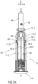
- an exemplary drug delivery device 10 is shown in Figures 1A and 1B .
- Device 10 is configured to inject a drug or medicament into a patient's body.
- Device 10 includes a housing 11 which typically contains a reservoir or cartridge containing the medicament to be injected (e.g., a syringe 24 or a container) and the components required to facilitate one or more steps of the delivery process.
- a housing 11 typically contains a reservoir or cartridge containing the medicament to be injected (e.g., a syringe 24 or a container) and the components required to facilitate one or more steps of the delivery process.
- Device 10 can also include a cap assembly 12 that can be detachably mounted to the housing 11, in particular on a distal or front end D of the device 10. Typically, a user must remove cap assembly or cap 12 from housing 11 before device 10 can be operated.
- housing 11 is substantially cylindrical and has a substantially constant diameter along the longitudinal axis X.
- the housing 11 has a distal region 20 and a proximal region 21.
- distal refers to a location that is relatively closer to a site of injection
- proximal refers to a location that is relatively further away from the injection site.
- Device 10 can also include a needle sleeve 13 coupled to the housing 11 to permit movement of the sleeve 13 relative to the housing 11.
- the sleeve 13 can move in a longitudinal direction parallel to longitudinal axis X.
- movement of the sleeve 13 in a proximal direction can permit a needle 17 to extend from distal region 20 of housing 11.
- Insertion of the needle 17 can occur via several mechanisms.
- the needle 17 may be fixedly located relative to housing 11 and initially be located within an extended needle sleeve 13.
- buttons 22 are located at a proximal or back end P of the housing 11.
- button 22 could be located on a side of housing 11.
- the button 22 has been deleted and is replaced for instance by a sleeve trigger mechanism, e.g. provided by pushing the needle sleeve 13 inside the housing when the drug delivery device is put onto an injection side.
- Injection is the process by which a bung or piston 23 is moved from a proximal location within a cartridge, container or syringe 24 to a more distal location within the syringe 24 in order to force a medicament from the syringe 24 through needle 17.
- the needle 17 can be retracted within sleeve 13 or housing 11. Retraction can occur when sleeve 13 moves distally as a user removes device 10 from a patient's body. This can occur as needle 17 remains fixedly located relative to housing 11. Once a distal end of the sleeve 13 has moved past a distal end of the needle 17, and the needle 17 is covered, the sleeve 13 can be locked. Such locking can include locking any proximal movement of the sleeve 13 relative to the housing 11.
- Another form of needle retraction can occur if the needle 17 is moved relative to the housing 11. Such movement can occur if the syringe 24 within the housing 11 is moved in a proximal direction relative to the housing 11. This proximal movement can be achieved by using a retraction spring (not shown), located in the distal region 20. A compressed retraction spring, when activated, can supply sufficient force to the syringe 24 to move it in a proximal direction.
- any relative movement between the needle 17 and the housing 11 can be locked with a locking mechanism.
- button 22 or other components of device 10 can be locked as required.
- the housing may comprise a window 11a through which the syringe 24 can be monitored.
- the drug delivery device 10 comprises the housing 11 with a front case 11.1 and a rear case 11.2.
- the front case 11.1 is adapted to hold the medicament container or primary container 24, such as a syringe.
- the medicament primary container is referred to hereinafter as the "syringe 24".
- the syringe 24 may be a pre-filled syringe, in particular a 1.0 ml pre-filled syringe, containing a medicament and having the needle 17 arranged at a distal end of the syringe 24.
- the medicament container may be a primary container which includes the medicament and engages a removable needle (e.g., by threads, snaps, friction, etc.).
- the drug delivery device 10 may be configured as an autoinjector or as a manual drug delivery device.
- the drug delivery device 10 comprises an audible and/or tactile indicator 50 providing an audible and/or tactile indication to a user of the device 10 at the end of delivery of the medicament.
- the indicator 50 produces an audible and/or tactile feedback for a user or patient indicating completion of medicament delivery.
- the indicator 50 is provided to indicate to a user or a patient that the full dose of medicament was spent.
- the indicator 50 is disposed at the proximal end P of the device 10.
- the indicator 50 is arranged at a proximal end of the housing 11 and inside the housing 11.
- a trigger mechanism 60 is arranged between the indicator 50 and the plunger 40.
- the trigger mechanism 60 is configured to support the indicator 50 in an initial state of the device 10, for example during storage and transportation as well as during delivery of the medicament and to couple with the plunger 40 to activate the indicator 50 at an end of delivery.
- the trigger mechanism 60 engages with the plunger 40 to activate the audible and/or tactile indicator 50 at or near the end of delivery of the medicament.
- said indicator 50 upon activating of the indicator 50, can disengage from the support of the trigger mechanism 60.
- the trigger mechanism 60 is being engaging with the plunger 40 near or at the end of delivery of the medicament, the trigger mechanism 60 is being disengaged from the indicator 50 to activate it.
- the indicator 50 can deform or relax when its support is disengaged.
- the indicator 50 can disengage from the support by the trigger mechanism 60.
- the indicator 50 is engaged, e.g. in contact, with the trigger mechanism in the initial state and during injection.
- the trigger mechanism 60 supports the indicator 50 in an initial state, e.g. unbiased state, or in a biased state.
- the trigger mechanism 60 may hold or press the indicator 50 in or into an initial state, e.g. unbiased state, or in or into a biased state.
- the trigger mechanism 60 only supports the indicator 50 before its activation and releases it upon activating.
- the indicator 50 is formed as a biasing member, a spring, a laminated spring, a flat spring, a plate spring or a leaf spring.
- the trigger mechanism 60 comprises at least one structure, e.g. a protrusion, a flap, projection, resiliently abutting the plunger 40.
- the at least one structure resiliently abuts the plunger 40 before activating of the indicator 50.
- a part of the trigger mechanism 60 e.g. one surface side, for instance an outer side of the trigger mechanism 60, abuts and supports the indicator 50 and an opposite surface side, e.g. an inner side of the trigger mechanism 60, abuts the plunger 40 before activating of the indicator 50, e.g. before and during delivery of the medicament.
- the trigger mechanism 60 Upon activating of the indicator 50, the trigger mechanism 60 disengages from indicator 50 and a part of the trigger mechanism 60 couples or engages with the plunger 40.
- FIGS 2A to 4C respectively show embodiments of the indicator 50 which will be described further below.
- FIG 2A shows a longitudinal section of an exemplary embodiment of the rear case 11.2.
- the rear case 11.2 serves for example as a drive subassembly 11.4 of the drug delivery device 10.
- the drive sub assembly 11.4 is a sub assembly of the drug delivery device 10 and comprises the components required to deliver the medicament.
- the drive subassembly 11.4 comprises for example the rear case 11.2, the plunger 40, the drive spring 30 and the indicator 50.
- the drug delivery device 10 further comprises a front sub assembly (not shown separately) to allow for flexibility as to the time and location of manufacture of the subassemblies and final assembly with the syringe 24.
- the rear case 11.2 comprises two support arms 11.3 adapted to support an axial position of the syringe 24 during storage, transportation and medicament delivery.
- the support arms 11.3 project distally from a proximal case end 11.4 of the rear case 11.2.
- the rear case 11.2 further comprises additional flexible projections 11.5 that project distally from the distal end of the rear case 11.2 as well.
- the flexible projections 11.5 project distally from the distal end of the support arms 11.3.
- the projections 11.5 are adapted to damp impact forces and thus to stabilize the syringe 24 during storage, transportation and delivery.
- the indicator 50 is arranged on the housing 11, in particular on the rear case 11.2.
- the indicator 50 is arranged on an outer side of at least one of the support arms 11.3.
- the trigger mechanism 60 is also arranged on the rear case 11.2.
- the trigger mechanism 60 is arranged on an inner side of the support arm 11.3 and thus on a side opposite the side of the support arms 11.3 where the indicator 50 is arranged.
- the trigger mechanism 60 is adapted to damp impact forces and thus to stabilize the indicator 50 in its biased state during storage, transportation, and medicament delivery.
- the indicator 50 may arranged on a holder (not shown) which is arranged in the housing 11.
- the trigger mechanism 60 may then also be arranged on the holder in a similar manner as on the rear case 11.2.
- the indicator 50 is arranged within the device 10 at the proximal end P of housing 11.
- a proximal end of the plunger 40 is at least partially received within the rear case 11.2.
- the rear case 11.2 is closed at its outer proximal end 11.4.
- the indicator 50 is held in the rear case 11.2 such that the longitudinal axis X is in parallel with a longitudinal extension of the drug delivery device 10.
- the indicator 50 may be coupled to the drug delivery device 10 by a snap connection, wherein one or more of the tabs 50.1 are engaged within a number of corresponding openings 11.6 in the rear case 11.2.
- the indicator 50 is held in the rear case 11.2 by a frictional connection, such as a screw or rivet connection or interference fit.
- Figures 2A and 2C show the indicator 50 in a pre-assembly state and initial or relaxed state S1.
- Figure 2B shows the indicator 50 in an assembly state in the rear case 11.2 and in a primed or biased state S2 and figure 2D shows the indicator in the biased state S2, too.
- the indicator 50 comprises a resilient force member 50.2, e.g. having a substantially rectangular shape, comprising a longitudinal axis running in parallel to the longest side of the outer circumference of the resilient force member 50.2.
- the resilient force member 50.2 may have a triangular shape or any other geometrical shape suitable to couple the indicator 50 to the device 10, e.g. an autoinjector.
- the resilient force member 50.2 may be designed as a monostable leaf spring comprising a resilient material, e. g. spring steel or spring plastic.
- the resilient force member 50.2 is capable of residing in two states. That is, the resilient force member 50.2 may assume two different conformations, one of them stable with limited or no application of an external force and the other one unstable.
- these two states can include a first or relaxed state S1 (or pre-assembly state, or trigged state, or initial state), in which the resilient force member 50.2 has a first conformation.
- a second or biased state S2 or primed state
- the resilient force member 50.2 can have a second conformation.
- the resilient force member 50.2 is in the relaxed state S1 which can correspond to the pre-assembly state as well as to a state at the end of medicament delivery.
- the resilient force member 50.2 comprises a longitudinal bend 50.3.
- the longitudinal bend 50.3 can be arranged generally in the centre of the resilient force member 50.2 running in parallel to the longitudinal axis X.
- the longitudinal bend 50.3 can divide the indicator 50 into two wing-shaped sections angled to each other with an angle less than 180 degrees. In in the illustrated perspective of figures 2A and 2C , the wing-shaped sections are angled downwards.
- the resilient force member 50.2 can comprise one or more tabs 50.1 projecting perpendicularly to the longitudinal axis X from the outer circumference.
- the resilient force member 50.2 can include one, two, three, four or more tabs 50.1.
- the resilient force member 50.2 includes two tabs 50.1, wherein one of the tabs 50.1 is arranged opposite the other tab 50.1.
- the resilient force member 50.2 can include pairs of tabs 50.1 located generally opposite each other. The pairs of tabs 50.1 are arranged spaced to each other in the direction of the longitudinal axis X.
- the number and arrangement of the tabs 50.1 may differ from the shown exemplary embodiment.
- the tabs 50.1 may be angled with respect to the wing-shaped sections to facilitate assembly of the drug delivery device 10.
- the resilient force member 50.2 is bent in the centre about an axis A running perpendicular to the longitudinal axis X.
- the bending angle may be less than 90 degrees. This bending is achieved by applying a predetermined force onto or near the centre point of the resilient force member 50.2 when engaging the tabs 50.1 within the openings 11.6 in the rear case 11.2.
- the resilient force member 50.2 changes from the relaxed state S1 into the biased state S2.
- Two ends 50.4.1, 50.4.2 of the resilient force member 50.2 at opposite ends along the longitudinal axis X are angled upwards from the centre point 50.5 in the illustrated perspective of figure 2C , which shows the biased state S2.
- the biased state S2 corresponds with the primed state, wherein the resilient force member 50.2 stores a certain amount of energy.
- the resilient force member 50.2 is held in the biased state S2 as it is shown in figure 2C and described below.
- the resilient force member 50.2 is in the biased state S2 and held in the rear case 11.2 by the snap connection as described above.
- the distally pointing end 50.4.1 of the resilient force member 50.2 and the biased state S2 of the indicator 50 is supported and activated by the trigger mechanism 60 arranged on the support arm 11.3 as described further below.
- the proximally pointing end 50.4.2 of the resilient force member 50.2 is free and not in contact with any other component and located above the trigger mechanism 60 or another section of the rear case 11.2.
- the trigger mechanism 60 comprises at least one structure 60.1 resiliently abutting the plunger 40.
- the structure 60.1 may protrude from an indicator holder towards the plunger 40.
- the structure 60.1 may be formed as a fin.
- the protruding structure 60.1 is referred to hereinafter as "fin 60.1". Due to the support of the fin 60.1 on the plunger 40 during storage, transportation and delivery, the indicator 50 is supported in its biased state S2, too.
- the at least one fin 60.1 protrudes from the housing 11, in particular from the rear case 11.2, e.g. from its inner support arm 11.3 towards the plunger 40.
- the support arm 11.3 is formed as an indicator holder.
- the indicator 50 and the fin 60.1 are arranged on opposite surface side of the support arm 11.3.
- the indicator 50 is held on a surface side of arm 11.3 facing to the outer housing 11.
- the fin 60.1 is formed on the opposite side of the arm 11.3 facing inwards and towards to the plunger 40.
- the fin 60.1 may protrude from a separate indicator holder (not shown) towards the plunger 40.
- the separate indicator holder may be arranged between the indicator 50 and the plunger 40 within the housing 11.
- the fin 60.1 has an inclined surface 60.2.
- an upper or top surface of the fin 60.1 is rounded or inclined.
- the inclined surface 60.2 ensures guiding along the plunger 40 during delivery of the medicament.
- the fin 60.1 may comprise a proximal inclined end 60.3 and a distal stepped edge 60.4.
- the proximal inclined end 60.3 allows an easy coupling of the fin 60.1 with the plunger 40.
- the distal stepped edge 60.4 is configured to secure the coupling of the fin 60.1 with the plunger 40.
- the plunger 40 comprises at least one cut-out 40.1 adapted to receive the at least one fin 60.1 at the end of delivery, for example when the plunger 40 is in the distal position. Due to the fin 60.1 falling into the cut-out 40.1 at the end of delivery, the indicator 50 relaxes and generates an acoustic noise. Additionally, the indicator 50 may be configured to generate a tactile feedback on the outer housing 11, too. The indicator 50 thus provides an end-of-delivery feedback to a user.
- the cut-out 40.1 may comprise a lateral inclined edge 40.1.1. Such a lateral inclined edge 40.1.1 facilitates the fin 60.1 falling into the cut-out 40.1.
- the cut-out 40.1 may further comprise a distal stepped edge 40.1.2.
- the distal stepped edge 40.1.2 corresponds with the distal stepped edge 60.4 of the fin 60.1 to facilitate the coupling of the fin 60.1 and the cut-out 40.1.
- the trigger mechanism 60 comprises two adjacent fins 60.1 and the plunger 40 comprises two correspondingly adjacent cut-outs 40.1 adapted to receive the fins 60.1.
- the two fins 60.1 are arranged spaced to each other in the direction of the transversal direction.
- the pair of fins 60.1 protrudes from the inner surface of the rear case 11.2 facing the plunger 40 when received inside the housing 11.
- the radially inwardly protruding and adjacent fins 60.1 abut the plunger 40, thereby supporting the resilient force member 50.2 in its biased state S2.
- the number and arrangement of the fins 60.1 may differ from the shown exemplary embodiment.
- the number and arrangement of the indicators 50 and trigger mechanism 60 may differ from the shown exemplary embodiment.
- the device 10 may comprise two trigger mechanism 60 and two indicators 50 described above. Each of a pair of trigger mechanism 60 and indicators 50 may be arranged on one of the support arms 11.3 of the rear case 11.2.
- the plunger 40 is driven by a drive spring 30 that is arranged between the plunger 40 and the rear case 11.2.
- the drive spring 30 may be arranged within the plunger 40 and be pre-loaded such as to urge the plunger 40 towards the distal end D of the device 10.
- two circumferentially adjacent cut-outs 40.1 corresponding to the adjacent fins 60.1 of the trigger mechanism 60 are arranged near the proximal end P of the plunger 40.
- the plunger 40 is aligned in an angular position relative to the rear case 11.2 such that each of the fins 60.1 is axially aligned with its corresponding cut-out 40.1.
- the plunger 40 is translated in a distal direction towards a distal position until reaching a position at the end of the injection, where the fins 60.1 will snap into the cut-outs 40.1.
- the resilient force member 50.2 will relax from its biased state S2 into its relaxed state S1.
- An audible and/or tactile click emitted upon this relaxation indicates the end of the injection process to the user.
- the fins 60.1 are formed in the shape of shark fins with a proximally arranged inclined end 60.3 and with a distally arranged stepped edge 60.4.
- the resilient force member 50.2 relaxes immediately with a sharp click noise, when the plunger 40 reaches its distal end position.
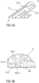
- Figure 4A shows a further aspect of the disclosure concerning the sleeve 13 comprising a guide rail 13.2.
- Figure 4B shows a guide pin 40.2 corresponding to the guide rail 13.2 and protruding from a proximal end of the plunger 40.
- Figure 4C is a schematic view of a guiding mechanism for guiding the plunger 40 along the needle sleeve 13 due to the interrelation of guide pin 40.2 and guide rail 13.2.
- the needle sleeve 13 is telescopically coupled to the housing 11 and has an inner surface 13.1 with at least one radially inwardly protruding guide rail 13.2 extending in parallel to the longitudinal axis X.
- the guide rail 13.2 is formed for example as a protruding rib elongated parallel to the longitudinal axis X.
- the plunger 40 may comprise at least one radially outwardly protruding guide pin 40.2.
- the guide pin 40.2 and the guide rail 13.2 are configured to engage each other, e.g. coaxially to the longitudinal axis X.
- the guide pin 40.2 engages the at least one guide rail 13.2 as best seen in figure 4C .
- the guide pin 40.2 may comprise a guide pin surface 40.2.1 engaging a corresponding guide rail surface 13.2.1 of the guide rail 13.2.
- the guide pin surface 40.2.1 and the guide rail surface 13.2.1 may be oppositely inclined to each other.
- the guide pin surface 40.2.1 and the guide rail surface 13.2.1 are engaged to each other in an angle between 30° and 60°, in particular between 40° and 50°.
- the guide pin 40.2 is formed as a protruding boss as shown in figure 4D .
- the guide pin 40.2 may comprise an inclined distal end 40.2.2.
- the inclined distal end 40.2.2 ensures correct positioning and alignment, in particular controlling rotation of the plunger 40 to ensure that the fin 60.1 will fall into the cut-out 40.1.
- the drug delivery device 10 may be an auto-injector, a pen-injector or a syringe.
- the primary container or syringe 24 may be prefilled with a drug.
- a drug or medicament can include at least one small or large molecule, or combinations thereof, in various types of formulations, for the treatment of one or more diseases.
- exemplary pharmaceutically active compounds may include small molecules; polypeptides, peptides and proteins (e.g., hormones, growth factors, antibodies, antibody fragments, and enzymes); carbohydrates and polysaccharides; and nucleic acids, double or single stranded DNA (including naked and cDNA), RNA, antisense nucleic acids such as antisense DNA and RNA, small interfering RNA (siRNA), ribozymes, genes, and oligonucleotides. Nucleic acids may be incorporated into molecular delivery systems such as vectors, plasmids, or liposomes. Mixtures of one or more of these drugs are also contemplated.
- a drug delivery device shall encompass any type of device or system configured to dispense a drug into a human or animal body.
- a drug delivery device may be an injection device (e.g., syringe, pen injector, auto injector, large-volume device, pump, perfusion system, or other device configured for intraocular, subcutaneous, intramuscular, or intravascular delivery), skin patch (e.g., osmotic, chemical, micro-needle), inhaler (e.g., nasal or pulmonary), implantable (e.g., coated stent, capsule), or feeding systems for the gastrointestinal tract.
- the presently described drugs may be particularly useful with injection devices that include a needle, e.g., a small gauge needle.
- the drug or medicament may be contained in a primary package or "drug container" adapted for use with a drug delivery device.
- the drug container may be, e.g., a cartridge, syringe, reservoir, or other vessel configured to provide a suitable chamber for storage (e.g., short- or long-term storage) of one or more pharmaceutically active compounds.
- the chamber may be designed to store a drug for at least one day (e.g., 1 to at least 30 days).
- the chamber may be designed to store a drug for about 1 month to about 2 years. Storage may occur at room temperature (e.g., about 20°C), or refrigerated temperatures (e.g., from about - 4°C to about 4°C).
- the drug container may be or may include a dual-chamber cartridge configured to store two or more components of a drug formulation (e.g., a drug and a diluent, or two different types of drugs) separately, one in each chamber.
- the two chambers of the dual-chamber cartridge may be configured to allow mixing between the two or more components of the drug or medicament prior to and/or during dispensing into the human or animal body.
- the two chambers may be configured such that they are in fluid communication with each other (e.g., by way of a conduit between the two chambers) and allow mixing of the two components when desired by a user prior to dispensing.
- the two chambers may be configured to allow mixing as the components are being dispensed into the human or animal body.
- the drug delivery devices and drugs described herein can be used for the treatment and/or prophylaxis of many different types of disorders.
- exemplary disorders include, e.g., diabetes mellitus or complications associated with diabetes mellitus such as diabetic retinopathy, thromboembolism disorders such as deep vein or pulmonary thromboembolism.
- Further exemplary disorders are acute coronary syndrome (ACS), angina, myocardial infarction, cancer, macular degeneration, inflammation, hay fever, atherosclerosis and/or rheumatoid arthritis.
- ACS acute coronary syndrome
- angina myocardial infarction
- cancer macular degeneration
- inflammation hay fever
- atherosclerosis and/or rheumatoid arthritis.
- Exemplary drugs for the treatment and/or prophylaxis of diabetes mellitus or complications associated with diabetes mellitus include an insulin, e.g., human insulin, or a human insulin analogue or derivative, a glucagon-like peptide (GLP-1), GLP-1 analogues or GLP-1 receptor agonists, or an analogue or derivative thereof, a dipeptidyl peptidase-4 (DPP4) inhibitor, or a pharmaceutically acceptable salt or solvate thereof, or any mixture thereof.
- the term "derivative” refers to any substance which is sufficiently structurally similar to the original substance so as to have substantially similar functionality or activity (e.g., therapeutic effectiveness).
- Exemplary insulin analogues are Gly(A21), Arg(B31), Arg(B32) human insulin (insulin glargine); Lys(B3), Glu(B29) human insulin; Lys(B28), Pro(B29) human insulin; Asp(B28) human insulin; human insulin, wherein proline in position B28 is replaced by Asp, Lys, Leu, Val or Ala and wherein in position B29 Lys may be replaced by Pro; Ala(B26) human insulin; Des(B28-B30) human insulin; Des(B27) human insulin and Des(B30) human insulin.
- Exemplary insulin derivatives are, for example, B29-N-myristoyl-des(B30) human insulin; B29-N-palmitoyl-des(B30) human insulin; B29-N-myristoyl human insulin; B29-N-palmitoyl human insulin; B28-N-myristoyl LysB28ProB29 human insulin; B28-N-palmitoyl-LysB28ProB29 human insulin; B30-N-myristoyl-ThrB29LysB30 human insulin; B30-N-palmitoyl- ThrB29LysB30 human insulin; B29-N-(N-palmitoyl-gamma-glutamyl)-des(B30) human insulin; B29-N-(N-lithocholyl-gamma-glutamyl)-des(B30) human insulin; B29-N-( ⁇ -carboxyheptadecanoyl)-des(B30) human insulin and B29-N
- GLP-1, GLP-1 analogues and GLP-1 receptor agonists are, for example: Lixisenatide / AVE0010 / ZP10 / Lyxumia, Exenatide / Exendin-4 / Byetta / Bydureon / ITCA 650 / AC-2993 (a 39 amino acid peptide which is produced by the salivary glands of the Gila monster), Liraglutide / Victoza, Semaglutide, Taspoglutide, Syncria / Albiglutide, Dulaglutide, rExendin-4, CJC-1134-PC, PB-1023, TTP-054, Langlenatide / HM-11260C, CM-3, GLP-1 Eligen, ORMD-0901, NN-9924, NN-9926, NN-9927, Nodexen, Viador-GLP-1, CVX-096, ZYOG-1, ZYD-1, GSK-2374697, DA-3091, MAR-701
- An exemplary oligonucleotide is, for example: mipomersen / Kynamro, a cholesterol-reducing antisense therapeutic for the treatment of familial hypercholesterolemia.
- DPP4 inhibitors are Vildagliptin, Sitagliptin, Denagliptin, Saxagliptin, Berberine.
- hormones include hypophysis hormones or hypothalamus hormones or regulatory active peptides and their antagonists, such as Gonadotropine (Follitropin, Lutropin, Choriongonadotropin, Menotropin), Somatropine (Somatropin), Desmopressin, Terlipressin, Gonadorelin, Triptorelin, Leuprorelin, Buserelin, Nafarelin, and Goserelin.
- Gonadotropine Follitropin, Lutropin, Choriongonadotropin, Menotropin
- Somatropine Somatropin
- Desmopressin Terlipressin
- Gonadorelin Triptorelin
- Leuprorelin Buserelin
- Nafarelin Nafarelin
- Goserelin Goserelin.
- Exemplary polysaccharides include a glucosaminoglycane, a hyaluronic acid, a heparin, a low molecular weight heparin or an ultra-low molecular weight heparin or a derivative thereof, or a sulphated polysaccharide, e.g. a poly-sulphated form of the above-mentioned polysaccharides, and/or a pharmaceutically acceptable salt thereof.
- An example of a pharmaceutically acceptable salt of a poly-sulphated low molecular weight heparin is enoxaparin sodium.
- An example of a hyaluronic acid derivative is Hylan G-F 20 / Synvisc, a sodium hyaluronate.
- antibody refers to an immunoglobulin molecule or an antigen-binding portion thereof.
- antigen-binding portions of immunoglobulin molecules include F(ab) and F(ab') 2 fragments, which retain the ability to bind antigen.
- the antibody can be polyclonal, monoclonal, recombinant, chimeric, de-immunized or humanized, fully human, non-human, (e.g., murine), or single chain antibody.
- the antibody has effector function and can fix complement.
- the antibody has reduced or no ability to bind an Fc receptor.
- the antibody can be an isotype or subtype, an antibody fragment or mutant, which does not support binding to an Fc receptor, e.g., it has a mutagenized or deleted Fc receptor binding region.
- fragment refers to a polypeptide derived from an antibody polypeptide molecule (e.g., an antibody heavy and/or light chain polypeptide) that does not comprise a full-length antibody polypeptide, but that still comprises at least a portion of a full-length antibody polypeptide that is capable of binding to an antigen.
- Antibody fragments can comprise a cleaved portion of a full length antibody polypeptide, although the term is not limited to such cleaved fragments.
- Antibody fragments that are useful in the present disclosure include, for example, Fab fragments, F(ab')2 fragments, scFv (single-chain Fv) fragments, linear antibodies, monospecific or multispecific antibody fragments such as bispecific, trispecific, and multispecific antibodies (e.g., diabodies, triabodies, tetrabodies), minibodies, chelating recombinant antibodies, tribodies or bibodies, intrabodies, nanobodies, small modular immunopharmaceuticals (SMIP), binding-domain immunoglobulin fusion proteins, camelized antibodies, and VHH containing antibodies. Additional examples of antigen-binding antibody fragments are known in the art.
- CDR complementarity-determining region
- framework region refers to amino acid sequences within the variable region of both heavy and light chain polypeptides that are not CDR sequences, and are primarily responsible for maintaining correct positioning of the CDR sequences to permit antigen binding.
- framework regions themselves typically do not directly participate in antigen binding, as is known in the art, certain residues within the framework regions of certain antibodies can directly participate in antigen binding or can affect the ability of one or more amino acids in CDRs to interact with antigen.
- Exemplary antibodies are anti PCSK-9 mAb (e.g., Alirocumab), anti IL-6 mAb (e.g., Sarilumab), and anti IL-4 mAb (e.g., Dupilumab).
- anti PCSK-9 mAb e.g., Alirocumab
- anti IL-6 mAb e.g., Sarilumab
- anti IL-4 mAb e.g., Dupilumab
- the compounds described herein may be used in pharmaceutical formulations comprising (a) the compound(s) or pharmaceutically acceptable salts thereof, and (b) a pharmaceutically acceptable carrier.
- the compounds may also be used in pharmaceutical formulations that include one or more other active pharmaceutical ingredients or in pharmaceutical formulations in which the present compound or a pharmaceutically acceptable salt thereof is the only active ingredient.
- the pharmaceutical formulations of the present disclosure encompass any formulation made by admixing a compound described herein and a pharmaceutically acceptable carrier.
- Pharmaceutically acceptable salts of any drug described herein are also contemplated for use in drug delivery devices.
- Pharmaceutically acceptable salts are for example acid addition salts and basic salts.
- Acid addition salts are e.g. HCl or HBr salts.
- Basic salts are e.g. salts having a cation selected from an alkali or alkaline earth metal, e.g.
- R1 to R4 independently of each other mean: hydrogen, an optionally substituted C1-C6-alkyl group, an optionally substituted C2-C6-alkenyl group, an optionally substituted C6-C10-aryl group, or an optionally substituted C6-C10-heteroaryl group.
- R1 to R4 independently of each other mean: hydrogen, an optionally substituted C1-C6-alkyl group, an optionally substituted C2-C6-alkenyl group, an optionally substituted C6-C10-aryl group, or an optionally substituted C6-C10-heteroaryl group.
- solvates are for example hydrates or alkanolates such as methanolates or ethanolates.
Landscapes
- Health & Medical Sciences (AREA)
- Engineering & Computer Science (AREA)
- Hematology (AREA)
- Anesthesiology (AREA)
- Biomedical Technology (AREA)
- Heart & Thoracic Surgery (AREA)
- Vascular Medicine (AREA)
- Life Sciences & Earth Sciences (AREA)
- Animal Behavior & Ethology (AREA)
- General Health & Medical Sciences (AREA)
- Public Health (AREA)
- Veterinary Medicine (AREA)
- Environmental & Geological Engineering (AREA)
- Infusion, Injection, And Reservoir Apparatuses (AREA)
Description
- The present disclosure relates to a drug delivery device comprising an audible and/or tactile indicator mechanism.
- Administering an injection is a process which presents a number of risks and challenges for users and healthcare professionals, both mental and physical. Drug delivery devices typically fall into two categories - manual drug delivery devices or autoinjectors. In a conventional manual device, manual force is required to drive a medicament through a needle. This is typically done by some form of plunger that has to be continuously pressed during the injection. There are numerous disadvantages associated with this approach. For example, if the plunger is released prematurely, the injection will stop and may not deliver an intended dose. Further, the force required to push the plunger may be too high (e.g., if the user is elderly or a child). And, aligning the injection device, administering the injection and keeping the injection device still during the injection may require dexterity which some patients (e.g., elderly patients, children, arthritic patients, etc.) may not have.
- Autoinjector devices aim to make self-injection easier for patients. A conventional autoinjector may provide the force for administering the injection by a spring, and trigger button or other mechanism may be used to activate the injection. Autoinjectors may be single-use or reusable devices.
-
WO 2016/193344 discloses a drug delivery device according to the state of the art. - It is desirable to administer the full dose in order to achieve full effectiveness of the medicament within the patient.
- An object of the present disclosure is to provide an improved drug delivery device.
- The object is achieved by a drug delivery device according to claim 1.
- Exemplary embodiments are provided in the dependent claims.
- According to the present disclosure, a drug delivery device comprises at least a housing adapted to receive a cartridge or primary container with a piston and a plunger slidably disposed in the housing and adapted to drive the piston for delivering a drug or a medicament. The device further comprises a drive spring pre-loaded between the housing and the plunger so as to urge the plunger towards a distal direction. Furthermore, an audible and/or tactile indicator, e.g. a resilient force member, is provided, e.g. disposed at a proximal end of the device, in particular at a proximal end of the housing. A trigger mechanism for activating the indicator is provided and arranged between the indicator and the plunger, wherein the trigger mechanism is configured to support the indicator in an initial state of the device and/or during delivery of the medicament and to couple with the plunger to activate the audible and/or tactile indicator at or near an end of delivery, in particular when the plunger is in a distal position.
- In particular, the trigger mechanism engages with the plunger to activate the audible and/or tactile indicator at or near the end of delivery of the medicament. In an exemplary embodiment, upon activating of the indicator said indicator disengages from the support of the trigger mechanism.
- According to another aspect, as the trigger mechanism is being engaging with the plunger the trigger mechanism is being disengaged from the indicator to activate the indicator. In particular, the indicator can deform or relax when its support is disengaged. For instance, the indicator can disengage from the support by the trigger mechanism.
- According to the disclosure, the indicator is engaged, e.g. in contact, with the trigger mechanism in the initial state and during injection. In particular, the trigger mechanism supports the indicator in an initial state, e.g. unbiased state, or in a biased state. Alternatively, the trigger mechanism may hold or press the indicator in or into an initial state, e.g. unbiased state, or in or into a biased state. Furthermore, the trigger mechanism only supports the indicator before its activation.
- In particular, the housing may comprise an inner surface forming a cavity configured to retain the cartridge or a drug container or primary container. The primary container comprises an inner surface forming a cavity configured to slidably receive the piston. Due to coupling of the plunger and the piston, the piston moves in the distal direction when the plunger moves in the distal direction for delivering the medicament.
- Such a drug delivery device ensures that the trigger mechanism fires or activates the indicator regardless of the length of the plunger. Hence, the length of the plunger could be changed without affecting activation or firing of the indicator. Furthermore, the number of parts, which would have to be replaced to accommodate a change in dose delivered by the drug delivery device, is minimised.
- In an exemplary embodiment, the trigger mechanism comprises at least one structure resiliently abutting the plunger. In particular, the at least one structure resiliently abuts the plunger before activating of the indicator. The at least one structure may protrude from an indicator holder towards the plunger. Alternatively, the at least one structure may protrude from the housing towards the plunger. The housing can also be configured to hold the indicator. In this embodiment, the holder may be formed as a part of an inner housing so a separate indicator holder is not required. In detail, the structure may protrude from the housing, for example from an inner part of the housing towards the plunger.
- According to another aspect of the present disclosure, the structure may have an inclined surface. The inclined surface ensures guiding and coupling with the plunger. In particular, the structure may comprise a proximal inclined end and a distal stepped edge. The distal stepped edge secures coupling with the plunger.
- In an exemplary embodiment, the structure comprises at least one fin.
- Furthermore, the plunger may comprise at least one cut-out adapted to receive the at least one structure at or near the end of delivery, in particular when the plunger is in a distal position.
- In an exemplary embodiment, the cut-out comprises a lateral inclined edge. The lateral inclined edge supports and ensures catching of the fin. Furthermore, the cut-out may comprise a distal stepped edge. This edge secures the coupling with the fin, in particular with the distal stepped edge of the fin.
- In a further exemplary embodiment, the indicator comprises two adjacent fins and the plunger comprises two corresponding adjacent cut-outs adapted to receive the fins.
- According to another aspect of the disclosure, a needle sleeve is telescopically coupled to the housing and has an inner surface with at least one radially inwardly protruding guide rail extending in parallel to a longitudinal axis.
- Furthermore, the plunger may comprise at least one radially outwardly protruding guide pin.
- In an exemplary embodiment, the guide pin and the guide rail are configured to engage each other, e.g. coaxially to the longitudinal axis.
- According to a further aspect of the disclosure, the guide pin may comprise a guide pin surface engaging a corresponding guide rail surface of the guide rail. In particular, the guide pin surface and the guide rail surface may be oppositely inclined to each other. For example, the guide pin surface and the guide rail surface may be engaged to each other in an angle between 30° and 60°, in particular between 40° and 50°.
- In an exemplary embodiment, the guide pin is formed as a protruding boss. The guide pin may comprise an inclined distal end. The inclined distal end ensures correct positioning and alignment, in particular for controlling rotation of the plunger to ensure that the fin will fall into the cut-out.
- Furthermore, the guide rail may be formed as a protruding elongated rib extending in parallel to the longitudinal axis. The elongated rib ensures a guiding of the pin during delivery of the medicament.
- Moreover, the drug delivery device may be an auto-injector, a pen-injector or a syringe. The primary container may be prefilled with a drug.
- The drug delivery device, as described herein, may be configured to inject a drug or medicament into a patient. For example, delivery could be sub-cutaneous, intra-muscular, or intravenous. Such a device could be operated by a patient or care-giver, such as a nurse or physician, and can include various types of safety syringe, pen-injector, or auto-injector.
- The device can include a cartridge-based system that requires piercing a sealed ampule before use. Volumes of medicament delivered with these various devices can range from about 0.5 ml to about 2 ml. Yet another device can include a large volume device ("LVD") or patch pump, configured to adhere to a patient's skin for a period of time (e.g., about 5, 15, 30, 60, or 120 minutes) to deliver a "large" volume of medicament (typically about 2 ml to about 5 ml).
- In combination with a specific medicament, the presently described devices may also be customized in order to operate within required specifications. For example, the device may be customized to inject a medicament within a certain time period (e.g., about 3 to about 20 seconds for auto-injectors, and about 10 minutes to about 60 minutes for an LVD). Other specifications can include a low or minimal level of discomfort, or to certain conditions related to human factors, shelf-life, expiry, biocompatibility, environmental considerations, etc. Such variations can arise due to various factors, such as, for example, a drug ranging in viscosity from about 3 cP to about 50 cP (0.003 - 0.05 Pa·s).
- Consequently, a drug delivery device will often include a hollow needle ranging from about 25 to about 31 Gauge (0.51 - 0.25 O.D. mm) in size. Common sizes are 27 and 29 Gauge (0.41 - 0.33 O.D. mm).
- The delivery devices described herein can also include one or more automated functions. For example, one or more of needle insertion, medicament injection, and needle retraction can be automated. Energy for one or more automation steps can be provided by one or more energy sources. Energy sources can include, for example, mechanical, pneumatic, chemical, or electrical energy. For example, mechanical energy sources can include springs, levers, elastomers, or other mechanical mechanisms to store or release energy. One or more energy sources can be combined into a single device. Devices can further include gears, valves, or other mechanisms to convert energy into movement of one or more components of a device. The one or more automated functions of an auto-injector may be activated via an activation mechanism. Such an activation mechanism can include one or more of a button, a lever, a needle sleeve, or other activation component. Activation may be a one-step or multi-step process. That is, a user may need to activate one or more activation mechanism in order to cause the automated function. For example, a user may depress a needle sleeve against their body in order to cause injection of a medicament. In other devices, a user may be required to depress a button and retract a needle shield in order to cause injection.
- In addition, such activation may activate one or more mechanisms. For example, an activation sequence may activate at least two of needle insertion, medicament injection, and needle retraction. Some devices may also require a specific sequence of steps to cause the one or more automated functions to occur. Other devices may operate with sequence independent steps.
- Some delivery devices can include one or more functions of a safety syringe, pen-injector, or auto-injector. For example, a delivery device could include a mechanical energy source configured to automatically inject a medicament (as typically found in an auto-injector) and a dose setting mechanism (as typically found in a pen-injector).
- Further scope of applicability of the present disclosure will become apparent from the detailed description given hereinafter.
- The present disclosure will become more fully understood from the detailed description given below and the accompanying drawings, which are given by way of illustration only, and do not limit the present disclosure, and wherein:
- Figures 1A, 1B
- are schematic views of a drug delivery device comprising a tactile and/or audible indicator,
- Figure 2A
- is a schematic perspective view and a longitudinal section of a proximal end of the drug delivery device,
- Figure 2B
- is a schematic exploded view of a proximal end of the drug delivery device with a trigger mechanism arranged between an indicator and a plunger,
- Figures 2C, 2D
- are schematic perspective view of an indicator in an initial state and in a primed state,
- Figure 3A
- is a schematic perspective view of a proximal end of a plunger with cut-outs,
- Figure 3B
- is a schematic perspective view of a distal end of a rear case,
- Figure 4A
- is a schematic perspective view of a proximal end of a sleeve with a guide rail,
- Figure 4B
- is a schematic cross section of a proximal end of a drug delivery device with a plunger comprising a protruding guide pin,
- Figure 4C
- is a schematic view of a guiding mechanism for guiding a plunger along a needle sleeve, and
- Figure 4D
- is a schematic view of a proximal end of a plunger with a guide pin.
- Corresponding parts are marked with the same reference symbols in all figures.
- According to some embodiments of the present disclosure, an exemplary
drug delivery device 10 is shown inFigures 1A and 1B . -
Device 10, as described above, is configured to inject a drug or medicament into a patient's body. -
Device 10 includes ahousing 11 which typically contains a reservoir or cartridge containing the medicament to be injected (e.g., asyringe 24 or a container) and the components required to facilitate one or more steps of the delivery process. -
Device 10 can also include acap assembly 12 that can be detachably mounted to thehousing 11, in particular on a distal or front end D of thedevice 10. Typically, a user must remove cap assembly or cap 12 fromhousing 11 beforedevice 10 can be operated. - As shown,
housing 11 is substantially cylindrical and has a substantially constant diameter along the longitudinal axis X. Thehousing 11 has adistal region 20 and aproximal region 21. The term "distal" refers to a location that is relatively closer to a site of injection, and the term "proximal" refers to a location that is relatively further away from the injection site. -
Device 10 can also include aneedle sleeve 13 coupled to thehousing 11 to permit movement of thesleeve 13 relative to thehousing 11. For example, thesleeve 13 can move in a longitudinal direction parallel to longitudinal axis X. Specifically, movement of thesleeve 13 in a proximal direction can permit aneedle 17 to extend fromdistal region 20 ofhousing 11. - Insertion of the
needle 17 can occur via several mechanisms. For example, theneedle 17 may be fixedly located relative tohousing 11 and initially be located within anextended needle sleeve 13. - Proximal movement of the
sleeve 13 by placing a distal end ofsleeve 13 against a patient's body and movinghousing 11 in a distal direction orsleeve 13 in a proximal direction will uncover the distal end ofneedle 17. Such relative movement allows the distal end ofneedle 17 to extend into the patient's body. Such insertion is termed "manual" insertion as theneedle 17 is manually inserted via the patient's manual movement of thesleeve 13 relative to thehousing 11 and theneedle 17 or reverse. - Another form of insertion is "automated," whereby the
needle 17 moves relative tohousing 11. Such insertion can be triggered by movement ofsleeve 13 or by another form of activation, such as, for example, abutton 22. As shown inFigures 1A & 1B ,button 22 is located at a proximal or back end P of thehousing 11. However, in other embodiments,button 22 could be located on a side ofhousing 11. In further embodiments, thebutton 22 has been deleted and is replaced for instance by a sleeve trigger mechanism, e.g. provided by pushing theneedle sleeve 13 inside the housing when the drug delivery device is put onto an injection side. - Other manual or automated features can include drug injection, automatic needle insertion or needle retraction, or both. Injection is the process by which a bung or
piston 23 is moved from a proximal location within a cartridge, container orsyringe 24 to a more distal location within thesyringe 24 in order to force a medicament from thesyringe 24 throughneedle 17. - In some embodiments, an energy source, e.g. a
drive spring 30 is arranged in aplunger 40 and is under compression beforedevice 10 is activated. A proximal end of thedrive spring 30 can be fixed withinproximal region 21 ofhousing 11, and a distal end of thedrive spring 30 can be configured to apply a compressive force to a proximal surface ofpiston 23. Following activation, at least part of the energy stored in thedrive spring 30 can be applied to the proximal surface ofpiston 23. This compressive force can act onpiston 23 to move it in a distal direction. Such distal movement acts to compress the liquid medicament within thesyringe 24, forcing it out ofneedle 17. - Following injection, the
needle 17 can be retracted withinsleeve 13 orhousing 11. Retraction can occur whensleeve 13 moves distally as a user removesdevice 10 from a patient's body. This can occur asneedle 17 remains fixedly located relative tohousing 11. Once a distal end of thesleeve 13 has moved past a distal end of theneedle 17, and theneedle 17 is covered, thesleeve 13 can be locked. Such locking can include locking any proximal movement of thesleeve 13 relative to thehousing 11. - Another form of needle retraction can occur if the
needle 17 is moved relative to thehousing 11. Such movement can occur if thesyringe 24 within thehousing 11 is moved in a proximal direction relative to thehousing 11. This proximal movement can be achieved by using a retraction spring (not shown), located in thedistal region 20. A compressed retraction spring, when activated, can supply sufficient force to thesyringe 24 to move it in a proximal direction. - Following sufficient retraction, any relative movement between the
needle 17 and thehousing 11 can be locked with a locking mechanism. In addition,button 22 or other components ofdevice 10 can be locked as required. - In some embodiments, the housing may comprise a
window 11a through which thesyringe 24 can be monitored. - In the present specification, the term "distal section/end" refers to the section/end of the
device 10, or the sections/ends of the components thereof, which during use of thedevice 10 is located closest to a medicament delivery site of a patient. Correspondingly, the term "proximal section/end" refers to the section/end of thedevice 10, or the sections/ends of the components thereof, which during use of thedevice 10 is pointing away from the medicament delivery site of the patient. - In the shown exemplary embodiments, the
drug delivery device 10 comprises thehousing 11 with a front case 11.1 and a rear case 11.2. The front case 11.1 is adapted to hold the medicament container orprimary container 24, such as a syringe. The medicament primary container is referred to hereinafter as the "syringe 24". Thesyringe 24 may be a pre-filled syringe, in particular a 1.0 ml pre-filled syringe, containing a medicament and having theneedle 17 arranged at a distal end of thesyringe 24. In another exemplary embodiment, the medicament container may be a primary container which includes the medicament and engages a removable needle (e.g., by threads, snaps, friction, etc.). - The
drug delivery device 10 may be configured as an autoinjector or as a manual drug delivery device. - Moreover, the
drug delivery device 10 comprises an audible and/ortactile indicator 50 providing an audible and/or tactile indication to a user of thedevice 10 at the end of delivery of the medicament. In particular, theindicator 50 produces an audible and/or tactile feedback for a user or patient indicating completion of medicament delivery. In other words: Theindicator 50 is provided to indicate to a user or a patient that the full dose of medicament was spent. - In an exemplary embodiment, the
indicator 50 is disposed at the proximal end P of thedevice 10. For example, theindicator 50 is arranged at a proximal end of thehousing 11 and inside thehousing 11. - Further, a
trigger mechanism 60 is arranged between theindicator 50 and theplunger 40. Thetrigger mechanism 60 is configured to support theindicator 50 in an initial state of thedevice 10, for example during storage and transportation as well as during delivery of the medicament and to couple with theplunger 40 to activate theindicator 50 at an end of delivery. - In particular, the
trigger mechanism 60 engages with theplunger 40 to activate the audible and/ortactile indicator 50 at or near the end of delivery of the medicament. - In an exemplary embodiment, upon activating of the
indicator 50, saidindicator 50 can disengage from the support of thetrigger mechanism 60. In particular, as thetrigger mechanism 60 is being engaging with theplunger 40 near or at the end of delivery of the medicament, thetrigger mechanism 60 is being disengaged from theindicator 50 to activate it. For example, theindicator 50 can deform or relax when its support is disengaged. For instance, theindicator 50 can disengage from the support by thetrigger mechanism 60. - For example, the
indicator 50 is engaged, e.g. in contact, with the trigger mechanism in the initial state and during injection. In particular, thetrigger mechanism 60 supports theindicator 50 in an initial state, e.g. unbiased state, or in a biased state. Alternatively, thetrigger mechanism 60 may hold or press theindicator 50 in or into an initial state, e.g. unbiased state, or in or into a biased state. Furthermore, thetrigger mechanism 60 only supports theindicator 50 before its activation and releases it upon activating. - In an exemplary embodiment, the
indicator 50 is formed as a biasing member, a spring, a laminated spring, a flat spring, a plate spring or a leaf spring. - In an exemplary embodiment, the
trigger mechanism 60 comprises at least one structure, e.g. a protrusion, a flap, projection, resiliently abutting theplunger 40. In particular, the at least one structure resiliently abuts theplunger 40 before activating of theindicator 50. - In particular, a part of the
trigger mechanism 60, e.g. one surface side, for instance an outer side of thetrigger mechanism 60, abuts and supports theindicator 50 and an opposite surface side, e.g. an inner side of thetrigger mechanism 60, abuts theplunger 40 before activating of theindicator 50, e.g. before and during delivery of the medicament. Upon activating of theindicator 50, thetrigger mechanism 60 disengages fromindicator 50 and a part of thetrigger mechanism 60 couples or engages with theplunger 40. -
Figures 2A to 4C respectively show embodiments of theindicator 50 which will be described further below. -
Figure 2A shows a longitudinal section of an exemplary embodiment of the rear case 11.2. In an assembled state, the rear case 11.2 serves for example as a drive subassembly 11.4 of thedrug delivery device 10. - The drive sub assembly 11.4 is a sub assembly of the
drug delivery device 10 and comprises the components required to deliver the medicament. The drive subassembly 11.4 comprises for example the rear case 11.2, theplunger 40, thedrive spring 30 and theindicator 50. Thedrug delivery device 10 further comprises a front sub assembly (not shown separately) to allow for flexibility as to the time and location of manufacture of the subassemblies and final assembly with thesyringe 24. - According to the present embodiment, the rear case 11.2 comprises two support arms 11.3 adapted to support an axial position of the
syringe 24 during storage, transportation and medicament delivery. The support arms 11.3 project distally from a proximal case end 11.4 of the rear case 11.2. The rear case 11.2 further comprises additional flexible projections 11.5 that project distally from the distal end of the rear case 11.2 as well. In detail, the flexible projections 11.5 project distally from the distal end of the support arms 11.3. - The projections 11.5 are adapted to damp impact forces and thus to stabilize the
syringe 24 during storage, transportation and delivery. - In an exemplary embodiment, the
indicator 50 is arranged on thehousing 11, in particular on the rear case 11.2. In detail, theindicator 50 is arranged on an outer side of at least one of the support arms 11.3. In this embodiment, in which theindicator 50 is arranged on the rear case 11.2, thetrigger mechanism 60 is also arranged on the rear case 11.2. In detail, thetrigger mechanism 60 is arranged on an inner side of the support arm 11.3 and thus on a side opposite the side of the support arms 11.3 where theindicator 50 is arranged. Thetrigger mechanism 60 is adapted to damp impact forces and thus to stabilize theindicator 50 in its biased state during storage, transportation, and medicament delivery. - In an alternative embodiment, the
indicator 50 may arranged on a holder (not shown) which is arranged in thehousing 11. Thetrigger mechanism 60 may then also be arranged on the holder in a similar manner as on the rear case 11.2. - In an assembled state, the
indicator 50 is arranged within thedevice 10 at the proximal end P ofhousing 11. A proximal end of theplunger 40 is at least partially received within the rear case 11.2. The rear case 11.2 is closed at its outer proximal end 11.4. - In detail, the
indicator 50 is held in the rear case 11.2 such that the longitudinal axis X is in parallel with a longitudinal extension of thedrug delivery device 10. Theindicator 50 may be coupled to thedrug delivery device 10 by a snap connection, wherein one or more of the tabs 50.1 are engaged within a number of corresponding openings 11.6 in the rear case 11.2. In another exemplary embodiment, theindicator 50 is held in the rear case 11.2 by a frictional connection, such as a screw or rivet connection or interference fit. -
Figures 2A and2C show theindicator 50 in a pre-assembly state and initial or relaxed state S1.Figure 2B shows theindicator 50 in an assembly state in the rear case 11.2 and in a primed or biased state S2 andfigure 2D shows the indicator in the biased state S2, too. - The
indicator 50 comprises a resilient force member 50.2, e.g. having a substantially rectangular shape, comprising a longitudinal axis running in parallel to the longest side of the outer circumference of the resilient force member 50.2. In other embodiments, the resilient force member 50.2 may have a triangular shape or any other geometrical shape suitable to couple theindicator 50 to thedevice 10, e.g. an autoinjector. - The resilient force member 50.2 may be designed as a monostable leaf spring comprising a resilient material, e. g. spring steel or spring plastic. Thus, the resilient force member 50.2 is capable of residing in two states. That is, the resilient force member 50.2 may assume two different conformations, one of them stable with limited or no application of an external force and the other one unstable. For example, these two states can include a first or relaxed state S1 (or pre-assembly state, or trigged state, or initial state), in which the resilient force member 50.2 has a first conformation. In a second or biased state S2 (or primed state), the resilient force member 50.2 can have a second conformation. In
figure 2A , the resilient force member 50.2 is in the relaxed state S1 which can correspond to the pre-assembly state as well as to a state at the end of medicament delivery. - In a possible embodiment, the resilient force member 50.2 comprises a longitudinal bend 50.3. The longitudinal bend 50.3 can be arranged generally in the centre of the resilient force member 50.2 running in parallel to the longitudinal axis X. The longitudinal bend 50.3 can divide the
indicator 50 into two wing-shaped sections angled to each other with an angle less than 180 degrees. In in the illustrated perspective offigures 2A and2C , the wing-shaped sections are angled downwards. - Furthermore, the resilient force member 50.2 can comprise one or more tabs 50.1 projecting perpendicularly to the longitudinal axis X from the outer circumference. Specifically, the resilient force member 50.2 can include one, two, three, four or more tabs 50.1.
- As shown in
figures 2A to 2D , the resilient force member 50.2 includes two tabs 50.1, wherein one of the tabs 50.1 is arranged opposite the other tab 50.1. In another embodiment (not shown), the resilient force member 50.2 can include pairs of tabs 50.1 located generally opposite each other. The pairs of tabs 50.1 are arranged spaced to each other in the direction of the longitudinal axis X. In another exemplary embodiment, the number and arrangement of the tabs 50.1 may differ from the shown exemplary embodiment. In an exemplary embodiment, the tabs 50.1 may be angled with respect to the wing-shaped sections to facilitate assembly of thedrug delivery device 10. - For assembling the
indicator 50 into thedrug delivery device 10, the resilient force member 50.2 is bent in the centre about an axis A running perpendicular to the longitudinal axis X. The bending angle may be less than 90 degrees. This bending is achieved by applying a predetermined force onto or near the centre point of the resilient force member 50.2 when engaging the tabs 50.1 within the openings 11.6 in the rear case 11.2. As a result, the resilient force member 50.2 changes from the relaxed state S1 into the biased state S2. Two ends 50.4.1, 50.4.2 of the resilient force member 50.2 at opposite ends along the longitudinal axis X are angled upwards from the centre point 50.5 in the illustrated perspective offigure 2C , which shows the biased state S2. Hence, the biased state S2 corresponds with the primed state, wherein the resilient force member 50.2 stores a certain amount of energy. - After removing the applied force, the resilient force member 50.2 is held in the biased state S2 as it is shown in
figure 2C and described below. - The resilient force member 50.2 is in the biased state S2 and held in the rear case 11.2 by the snap connection as described above. The distally pointing end 50.4.1 of the resilient force member 50.2 and the biased state S2 of the
indicator 50 is supported and activated by thetrigger mechanism 60 arranged on the support arm 11.3 as described further below. - The proximally pointing end 50.4.2 of the resilient force member 50.2 is free and not in contact with any other component and located above the
trigger mechanism 60 or another section of the rear case 11.2. - After changing from the relaxed state S1 into the biased state S2 as described before, only a small force may be required to hold the resilient force member 50.2 in the biased state S2. This is achieved by the longitudinal bend 50.3 that provides a bent cross section of the resilient force member 50.2 which buckles into a new configuration by changing from the relaxed state S1 into the biased state S2. In this configuration, a stiffness of the material structure is significantly reduced and thus only a small holding force is required to maintain the resilient force member 50.2 in the biased state S2.
- In detail, the
trigger mechanism 60 comprises at least one structure 60.1 resiliently abutting theplunger 40. The structure 60.1 may protrude from an indicator holder towards theplunger 40. The structure 60.1 may be formed as a fin. The protruding structure 60.1 is referred to hereinafter as "fin 60.1". Due to the support of the fin 60.1 on theplunger 40 during storage, transportation and delivery, theindicator 50 is supported in its biased state S2, too. - In detail, the at least one fin 60.1 protrudes from the
housing 11, in particular from the rear case 11.2, e.g. from its inner support arm 11.3 towards theplunger 40. The support arm 11.3 is formed as an indicator holder. Theindicator 50 and the fin 60.1 are arranged on opposite surface side of the support arm 11.3. Theindicator 50 is held on a surface side of arm 11.3 facing to theouter housing 11. The fin 60.1 is formed on the opposite side of the arm 11.3 facing inwards and towards to theplunger 40. - Alternatively, the fin 60.1 may protrude from a separate indicator holder (not shown) towards the
plunger 40. The separate indicator holder may be arranged between theindicator 50 and theplunger 40 within thehousing 11. - In an exemplary embodiment, the fin 60.1 has an inclined surface 60.2. In particular, an upper or top surface of the fin 60.1 is rounded or inclined. The inclined surface 60.2 ensures guiding along the
plunger 40 during delivery of the medicament. - Further, the fin 60.1 may comprise a proximal inclined end 60.3 and a distal stepped edge 60.4. The proximal inclined end 60.3 allows an easy coupling of the fin 60.1 with the
plunger 40. The distal stepped edge 60.4 is configured to secure the coupling of the fin 60.1 with theplunger 40. - According to another aspect of the disclosure, the
plunger 40 comprises at least one cut-out 40.1 adapted to receive the at least one fin 60.1 at the end of delivery, for example when theplunger 40 is in the distal position. Due to the fin 60.1 falling into the cut-out 40.1 at the end of delivery, theindicator 50 relaxes and generates an acoustic noise. Additionally, theindicator 50 may be configured to generate a tactile feedback on theouter housing 11, too. Theindicator 50 thus provides an end-of-delivery feedback to a user. - Furthermore, the cut-out 40.1 may comprise a lateral inclined edge 40.1.1. Such a lateral inclined edge 40.1.1 facilitates the fin 60.1 falling into the cut-out 40.1. The cut-out 40.1 may further comprise a distal stepped edge 40.1.2. The distal stepped edge 40.1.2 corresponds with the distal stepped edge 60.4 of the fin 60.1 to facilitate the coupling of the fin 60.1 and the cut-out 40.1.
- In the exemplary embodiment, the
trigger mechanism 60 comprises two adjacent fins 60.1 and theplunger 40 comprises two correspondingly adjacent cut-outs 40.1 adapted to receive the fins 60.1. The two fins 60.1 are arranged spaced to each other in the direction of the transversal direction. The pair of fins 60.1 protrudes from the inner surface of the rear case 11.2 facing theplunger 40 when received inside thehousing 11. The radially inwardly protruding and adjacent fins 60.1 abut theplunger 40, thereby supporting the resilient force member 50.2 in its biased state S2. In another exemplary embodiment, the number and arrangement of the fins 60.1 may differ from the shown exemplary embodiment. - In another exemplary embodiment, the number and arrangement of the
indicators 50 andtrigger mechanism 60 may differ from the shown exemplary embodiment. Thedevice 10 may comprise twotrigger mechanism 60 and twoindicators 50 described above. Each of a pair oftrigger mechanism 60 andindicators 50 may be arranged on one of the support arms 11.3 of the rear case 11.2. - For delivering a medicament, as can be seen in more detail in an exploded view in
Figure 2B , theplunger 40 is driven by adrive spring 30 that is arranged between theplunger 40 and the rear case 11.2. Thedrive spring 30 may be arranged within theplunger 40 and be pre-loaded such as to urge theplunger 40 towards the distal end D of thedevice 10. - As can be seen in detail in
figures 3A and 3B , two circumferentially adjacent cut-outs 40.1 corresponding to the adjacent fins 60.1 of thetrigger mechanism 60 are arranged near the proximal end P of the plunger 40.Theplunger 40 is aligned in an angular position relative to the rear case 11.2 such that each of the fins 60.1 is axially aligned with its corresponding cut-out 40.1. During the injection, theplunger 40 is translated in a distal direction towards a distal position until reaching a position at the end of the injection, where the fins 60.1 will snap into the cut-outs 40.1. Thereby, the resilient force member 50.2 will relax from its biased state S2 into its relaxed state S1. An audible and/or tactile click emitted upon this relaxation indicates the end of the injection process to the user. - As shown in
figure 3B , the fins 60.1 are formed in the shape of shark fins with a proximally arranged inclined end 60.3 and with a distally arranged stepped edge 60.4. Thereby, the resilient force member 50.2 relaxes immediately with a sharp click noise, when theplunger 40 reaches its distal end position. -
Figure 4A shows a further aspect of the disclosure concerning thesleeve 13 comprising a guide rail 13.2.Figure 4B shows a guide pin 40.2 corresponding to the guide rail 13.2 and protruding from a proximal end of theplunger 40.Figure 4C is a schematic view of a guiding mechanism for guiding theplunger 40 along theneedle sleeve 13 due to the interrelation of guide pin 40.2 and guide rail 13.2. - In detail, the
needle sleeve 13 is telescopically coupled to thehousing 11 and has an inner surface 13.1 with at least one radially inwardly protruding guide rail 13.2 extending in parallel to the longitudinal axis X. The guide rail 13.2 is formed for example as a protruding rib elongated parallel to the longitudinal axis X. - Furthermore, the
plunger 40 may comprise at least one radially outwardly protruding guide pin 40.2. In an exemplary embodiment, the guide pin 40.2 and the guide rail 13.2 are configured to engage each other, e.g. coaxially to the longitudinal axis X. In particular, the guide pin 40.2 engages the at least one guide rail 13.2 as best seen infigure 4C . - In more detail, the guide pin 40.2 may comprise a guide pin surface 40.2.1 engaging a corresponding guide rail surface 13.2.1 of the guide rail 13.2.
- Furthermore, the guide pin surface 40.2.1 and the guide rail surface 13.2.1 may be oppositely inclined to each other. For example, the guide pin surface 40.2.1 and the guide rail surface 13.2.1 are engaged to each other in an angle between 30° and 60°, in particular between 40° and 50°.
- In an exemplary embodiment, the guide pin 40.2 is formed as a protruding boss as shown in
figure 4D . The guide pin 40.2 may comprise an inclined distal end 40.2.2. The inclined distal end 40.2.2 ensures correct positioning and alignment, in particular controlling rotation of theplunger 40 to ensure that the fin 60.1 will fall into the cut-out 40.1. - Moreover, the
drug delivery device 10 may be an auto-injector, a pen-injector or a syringe. The primary container orsyringe 24 may be prefilled with a drug. - The terms "drug" or "medicament" are used herein to describe one or more pharmaceutically active compounds. As described below, a drug or medicament can include at least one small or large molecule, or combinations thereof, in various types of formulations, for the treatment of one or more diseases. Exemplary pharmaceutically active compounds may include small molecules; polypeptides, peptides and proteins (e.g., hormones, growth factors, antibodies, antibody fragments, and enzymes); carbohydrates and polysaccharides; and nucleic acids, double or single stranded DNA (including naked and cDNA), RNA, antisense nucleic acids such as antisense DNA and RNA, small interfering RNA (siRNA), ribozymes, genes, and oligonucleotides. Nucleic acids may be incorporated into molecular delivery systems such as vectors, plasmids, or liposomes. Mixtures of one or more of these drugs are also contemplated.
- The term "drug delivery device" shall encompass any type of device or system configured to dispense a drug into a human or animal body. Without limitation, a drug delivery device may be an injection device (e.g., syringe, pen injector, auto injector, large-volume device, pump, perfusion system, or other device configured for intraocular, subcutaneous, intramuscular, or intravascular delivery), skin patch (e.g., osmotic, chemical, micro-needle), inhaler (e.g., nasal or pulmonary), implantable (e.g., coated stent, capsule), or feeding systems for the gastrointestinal tract. The presently described drugs may be particularly useful with injection devices that include a needle, e.g., a small gauge needle.
- The drug or medicament may be contained in a primary package or "drug container" adapted for use with a drug delivery device. The drug container may be, e.g., a cartridge, syringe, reservoir, or other vessel configured to provide a suitable chamber for storage (e.g., short- or long-term storage) of one or more pharmaceutically active compounds. For example, in some instances, the chamber may be designed to store a drug for at least one day (e.g., 1 to at least 30 days). In some instances, the chamber may be designed to store a drug for about 1 month to about 2 years. Storage may occur at room temperature (e.g., about 20°C), or refrigerated temperatures (e.g., from about - 4°C to about 4°C). In some instances, the drug container may be or may include a dual-chamber cartridge configured to store two or more components of a drug formulation (e.g., a drug and a diluent, or two different types of drugs) separately, one in each chamber. In such instances, the two chambers of the dual-chamber cartridge may be configured to allow mixing between the two or more components of the drug or medicament prior to and/or during dispensing into the human or animal body. For example, the two chambers may be configured such that they are in fluid communication with each other (e.g., by way of a conduit between the two chambers) and allow mixing of the two components when desired by a user prior to dispensing. Alternatively or in addition, the two chambers may be configured to allow mixing as the components are being dispensed into the human or animal body.
- The drug delivery devices and drugs described herein can be used for the treatment and/or prophylaxis of many different types of disorders. Exemplary disorders include, e.g., diabetes mellitus or complications associated with diabetes mellitus such as diabetic retinopathy, thromboembolism disorders such as deep vein or pulmonary thromboembolism. Further exemplary disorders are acute coronary syndrome (ACS), angina, myocardial infarction, cancer, macular degeneration, inflammation, hay fever, atherosclerosis and/or rheumatoid arthritis.
- Exemplary drugs for the treatment and/or prophylaxis of diabetes mellitus or complications associated with diabetes mellitus include an insulin, e.g., human insulin, or a human insulin analogue or derivative, a glucagon-like peptide (GLP-1), GLP-1 analogues or GLP-1 receptor agonists, or an analogue or derivative thereof, a dipeptidyl peptidase-4 (DPP4) inhibitor, or a pharmaceutically acceptable salt or solvate thereof, or any mixture thereof. As used herein, the term "derivative" refers to any substance which is sufficiently structurally similar to the original substance so as to have substantially similar functionality or activity (e.g., therapeutic effectiveness).
- Exemplary insulin analogues are Gly(A21), Arg(B31), Arg(B32) human insulin (insulin glargine); Lys(B3), Glu(B29) human insulin; Lys(B28), Pro(B29) human insulin; Asp(B28) human insulin; human insulin, wherein proline in position B28 is replaced by Asp, Lys, Leu, Val or Ala and wherein in position B29 Lys may be replaced by Pro; Ala(B26) human insulin; Des(B28-B30) human insulin; Des(B27) human insulin and Des(B30) human insulin.
- Exemplary insulin derivatives are, for example, B29-N-myristoyl-des(B30) human insulin; B29-N-palmitoyl-des(B30) human insulin; B29-N-myristoyl human insulin; B29-N-palmitoyl human insulin; B28-N-myristoyl LysB28ProB29 human insulin; B28-N-palmitoyl-LysB28ProB29 human insulin; B30-N-myristoyl-ThrB29LysB30 human insulin; B30-N-palmitoyl- ThrB29LysB30 human insulin; B29-N-(N-palmitoyl-gamma-glutamyl)-des(B30) human insulin; B29-N-(N-lithocholyl-gamma-glutamyl)-des(B30) human insulin; B29-N-(ω-carboxyheptadecanoyl)-des(B30) human insulin and B29-N-(ω)-carboxyheptadecanoyi) human insulin. Exemplary GLP-1, GLP-1 analogues and GLP-1 receptor agonists are, for example: Lixisenatide / AVE0010 / ZP10 / Lyxumia, Exenatide / Exendin-4 / Byetta / Bydureon / ITCA 650 / AC-2993 (a 39 amino acid peptide which is produced by the salivary glands of the Gila monster), Liraglutide / Victoza, Semaglutide, Taspoglutide, Syncria / Albiglutide, Dulaglutide, rExendin-4, CJC-1134-PC, PB-1023, TTP-054, Langlenatide / HM-11260C, CM-3, GLP-1 Eligen, ORMD-0901, NN-9924, NN-9926, NN-9927, Nodexen, Viador-GLP-1, CVX-096, ZYOG-1, ZYD-1, GSK-2374697, DA-3091, MAR-701, MAR709, ZP-2929, ZP-3022, TT-401, BHM-034. MOD-6030, CAM-2036, DA-15864, ARI-2651, ARI-2255, Exenatide-XTEN and Glucagon-Xten.
- An exemplary oligonucleotide is, for example: mipomersen / Kynamro, a cholesterol-reducing antisense therapeutic for the treatment of familial hypercholesterolemia.
- Exemplary DPP4 inhibitors are Vildagliptin, Sitagliptin, Denagliptin, Saxagliptin, Berberine.
- Exemplary hormones include hypophysis hormones or hypothalamus hormones or regulatory active peptides and their antagonists, such as Gonadotropine (Follitropin, Lutropin, Choriongonadotropin, Menotropin), Somatropine (Somatropin), Desmopressin, Terlipressin, Gonadorelin, Triptorelin, Leuprorelin, Buserelin, Nafarelin, and Goserelin.
- Exemplary polysaccharides include a glucosaminoglycane, a hyaluronic acid, a heparin, a low molecular weight heparin or an ultra-low molecular weight heparin or a derivative thereof, or a sulphated polysaccharide, e.g. a poly-sulphated form of the above-mentioned polysaccharides, and/or a pharmaceutically acceptable salt thereof. An example of a pharmaceutically acceptable salt of a poly-sulphated low molecular weight heparin is enoxaparin sodium. An example of a hyaluronic acid derivative is
Hylan G-F 20 / Synvisc, a sodium hyaluronate. - The term "antibody", as used herein, refers to an immunoglobulin molecule or an antigen-binding portion thereof. Examples of antigen-binding portions of immunoglobulin molecules include F(ab) and F(ab')2 fragments, which retain the ability to bind antigen. The antibody can be polyclonal, monoclonal, recombinant, chimeric, de-immunized or humanized, fully human, non-human, (e.g., murine), or single chain antibody. In some embodiments, the antibody has effector function and can fix complement. In some embodiments, the antibody has reduced or no ability to bind an Fc receptor. For example, the antibody can be an isotype or subtype, an antibody fragment or mutant, which does not support binding to an Fc receptor, e.g., it has a mutagenized or deleted Fc receptor binding region.
- The terms "fragment" or "antibody fragment" refer to a polypeptide derived from an antibody polypeptide molecule (e.g., an antibody heavy and/or light chain polypeptide) that does not comprise a full-length antibody polypeptide, but that still comprises at least a portion of a full-length antibody polypeptide that is capable of binding to an antigen. Antibody fragments can comprise a cleaved portion of a full length antibody polypeptide, although the term is not limited to such cleaved fragments. Antibody fragments that are useful in the present disclosure include, for example, Fab fragments, F(ab')2 fragments, scFv (single-chain Fv) fragments, linear antibodies, monospecific or multispecific antibody fragments such as bispecific, trispecific, and multispecific antibodies (e.g., diabodies, triabodies, tetrabodies), minibodies, chelating recombinant antibodies, tribodies or bibodies, intrabodies, nanobodies, small modular immunopharmaceuticals (SMIP), binding-domain immunoglobulin fusion proteins, camelized antibodies, and VHH containing antibodies. Additional examples of antigen-binding antibody fragments are known in the art.
- The terms "Complementarity-determining region" or "CDR" refer to short polypeptide sequences within the variable region of both heavy and light chain polypeptides that are primarily responsible for mediating specific antigen recognition. The term "framework region" refers to amino acid sequences within the variable region of both heavy and light chain polypeptides that are not CDR sequences, and are primarily responsible for maintaining correct positioning of the CDR sequences to permit antigen binding. Although the framework regions themselves typically do not directly participate in antigen binding, as is known in the art, certain residues within the framework regions of certain antibodies can directly participate in antigen binding or can affect the ability of one or more amino acids in CDRs to interact with antigen.
- Exemplary antibodies are anti PCSK-9 mAb (e.g., Alirocumab), anti IL-6 mAb (e.g., Sarilumab), and anti IL-4 mAb (e.g., Dupilumab).
- The compounds described herein may be used in pharmaceutical formulations comprising (a) the compound(s) or pharmaceutically acceptable salts thereof, and (b) a pharmaceutically acceptable carrier. The compounds may also be used in pharmaceutical formulations that include one or more other active pharmaceutical ingredients or in pharmaceutical formulations in which the present compound or a pharmaceutically acceptable salt thereof is the only active ingredient. Accordingly, the pharmaceutical formulations of the present disclosure encompass any formulation made by admixing a compound described herein and a pharmaceutically acceptable carrier.
- Pharmaceutically acceptable salts of any drug described herein are also contemplated for use in drug delivery devices. Pharmaceutically acceptable salts are for example acid addition salts and basic salts. Acid addition salts are e.g. HCl or HBr salts. Basic salts are e.g. salts having a cation selected from an alkali or alkaline earth metal, e.g. Na+, or K+, or Ca2+, or an ammonium ion N+(R1)(R2)(R3)(R4), wherein R1 to R4 independently of each other mean: hydrogen, an optionally substituted C1-C6-alkyl group, an optionally substituted C2-C6-alkenyl group, an optionally substituted C6-C10-aryl group, or an optionally substituted C6-C10-heteroaryl group. Further examples of pharmaceutically acceptable salts are known to those of skill in the arts.
- Pharmaceutically acceptable solvates are for example hydrates or alkanolates such as methanolates or ethanolates.
-
- 10
- drug delivery device
- 11
- housing
- 11.1
- front case
- 11.2
- rear case
- 11.3
- support arm
- 11.4
- proximal end
- 11.5
- projection
- 11.6
- opening
- 12
- cap assembly
- 13
- needle sleeve
- 13.1
- inner surface
- 13.2
- guide rail
- 13.2.1
- surface
- 17
- needle
- 20
- distal region of the drug delivery device
- 21
- proximal region of the drug delivery device
- 22
- button
- 23
- piston
- 24
- primary container
- 30
- energy source, e.g. drive spring
- 40
- plunger
- 40.1
- cut-out
- 40.1.1
- lateral inclined surface
- 40.1.2
- distal stepped edge
- 40.2
- guide pin
- 40.2.1
- surface
- 40.2.2
- inclined end
- 50
- indicator
- 50.1
- tab
- 50.2
- resilient force member
- 50.3
- bend
- 50.4.1, 50.4.2
- end
- 60
- trigger mechanism
- 60.1
- structure (e.g. fin)
- 60.2
- inclined surface
- 60.3
- proximal inclined end
- 60.4
- distal stepped edge
- D
- distal end
- P
- proximal end
Claims (13)
- A drug delivery device (10) comprising at least:- a housing (11) adapted to receive a primary container (24) with a piston (23),- a plunger (40) slidably disposed in the housing (11) and adapted to drive the piston (23) for delivering a medicament,- a drive spring (30) pre-loaded between the housing (11) and the plunger (40) so as to urge the plunger (40) in a distal direction (D),- an audible and/or tactile indicator (50) providing an indication to a user at or near an end of delivery of the medicament, wherein the indicator (50) is a biasing member,- a trigger mechanism (60) arranged between the indicator (50) and the plunger (40),wherein the trigger mechanism (60) comprises at least one structure (60.1) resiliently abuting the plunger (40),wherein the plunger (40) provides at least one cut-out (40.1) adapted to receive the at least one structure (60.1) at or near the end of delivery of the medicament,wherein the cut-out (40.1) comprises a lateral inclined edge (40.1.1),wherein the drug delivery device (10) ensures that the trigger mechanism activates the audible and/or tactile indicator (50) regardless of the length of the plunger (40), andwherein the trigger mechanism (60) is configured- to support the indicator (50) in an initial state of the device (10) and during delivery of the medicament, wherein the at least one structure (60.1) is supported by the plunger (40) and thereby supports the indicator (50) in a biased state (S2), and- to couple with the plunger (40) to activate the audible and/or tactile indicator (50) at or near the end of delivery of the medicament, wherein the at least one cut-out (40.1) receives the at least one structure (60.1).
- The drug delivery device (10) according to claim 1, wherein upon activating of the indicator (50) said indicator (50) disengages from the support of the trigger mechanism (60).
- The drug delivery device (10) according to claim 1 or 2, comprising the primary container (24) prefilled with a dose of the medicament.
- The drug delivery device (10) according to any one of the preceding claims, wherein the at least one structure (60.1) protrudes from an indicator holder towards the plunger (40).
- The drug delivery device (10) according to any one of the preceding claims, wherein the at least one structure (60.1) protrudes from a housing (11, 11.3) towards the plunger (40).
- The drug delivery device (10) according to any one of the preceding claims, wherein the structure (60.1) has an inclined surface (60.2).
- The drug delivery device (10) according to any one of the preceding claims, wherein the structure (60.1) comprises a proximal inclined end (60.3), a distal stepped edge (60.4) and/or at least one fin or rib.
- The drug delivery device (10) according to any one of the preceding claims, wherein the cut-out (40.1) comprises a distal stepped edge (40.1.2).
- The drug delivery device (10) according to any one of the preceding claims, wherein the trigger mechanism (60) comprises two adjacent structures (60.1) and wherein the plunger (40) comprises two correspondingly adjacent cut-outs (40.1) adapted to receive the structures (60.1).
- The drug delivery device (10) according to any one of the preceding claims, wherein a needle sleeve (13) is telescopically coupled to the housing (11) and has an inner surface (13.1) with at least one radially inwardly protruding guide rail (13.2) extending in parallel to a longitudinal axis (X).
- The drug delivery device (10) according to claim 10, wherein the plunger (40) comprises at least one radially outwardly protruding guide pin (40.2) configured to engage the at least one guide rail (13.2).
- The drug delivery device (10) according to claim 11, wherein the guide pin (40.2) is formed as a protruding boss and/or comprises an inclined distal end (40.2.2).
- The drug delivery device (10) according to any one of the claims 10 to 12, wherein the guide rail (13.2) is formed as a protruding elongated rib in parallel to the longitudinal axis (X).
Priority Applications (1)
| Application Number | Priority Date | Filing Date | Title |
|---|---|---|---|
| EP25150109.4A EP4527435A3 (en) | 2017-11-03 | 2018-11-01 | Drug delivery device |
Applications Claiming Priority (2)
| Application Number | Priority Date | Filing Date | Title |
|---|---|---|---|
| EP17306518 | 2017-11-03 | ||
| PCT/EP2018/079915 WO2019086561A1 (en) | 2017-11-03 | 2018-11-01 | Drug delivery device |
Related Child Applications (1)
| Application Number | Title | Priority Date | Filing Date |
|---|---|---|---|
| EP25150109.4A Division EP4527435A3 (en) | 2017-11-03 | 2018-11-01 | Drug delivery device |
Publications (2)
| Publication Number | Publication Date |
|---|---|
| EP3703783A1 EP3703783A1 (en) | 2020-09-09 |
| EP3703783B1 true EP3703783B1 (en) | 2025-01-08 |
Family
ID=60302040
Family Applications (2)
| Application Number | Title | Priority Date | Filing Date |
|---|---|---|---|
| EP25150109.4A Pending EP4527435A3 (en) | 2017-11-03 | 2018-11-01 | Drug delivery device |
| EP18793225.6A Active EP3703783B1 (en) | 2017-11-03 | 2018-11-01 | Drug delivery device |
Family Applications Before (1)
| Application Number | Title | Priority Date | Filing Date |
|---|---|---|---|
| EP25150109.4A Pending EP4527435A3 (en) | 2017-11-03 | 2018-11-01 | Drug delivery device |
Country Status (6)
| Country | Link |
|---|---|
| US (2) | US11654246B2 (en) |
| EP (2) | EP4527435A3 (en) |
| JP (2) | JP7382928B2 (en) |
| CN (1) | CN111587132B (en) |
| DK (1) | DK3703783T3 (en) |
| WO (1) | WO2019086561A1 (en) |
Families Citing this family (19)
| Publication number | Priority date | Publication date | Assignee | Title |
|---|---|---|---|---|
| TW201707737A (en) | 2015-06-03 | 2017-03-01 | 賽諾菲阿凡提斯德意志有限公司 | Drug delivery device (1) |
| TW201709941A (en) | 2015-06-03 | 2017-03-16 | 賽諾菲阿凡提斯德意志有限公司 | Sound indicator (2) |
| TW201700118A (en) | 2015-06-03 | 2017-01-01 | 賽諾菲阿凡提斯德意志有限公司 | Drug delivery device (3) |
| TW201709940A (en) | 2015-06-03 | 2017-03-16 | 賽諾菲阿凡提斯德意志有限公司 | Sound indicator (1) |
| CN116322844A (en) * | 2020-11-13 | 2023-06-23 | 榭利(英国)有限公司 | drug delivery device |
| US20240252761A1 (en) * | 2021-06-02 | 2024-08-01 | Sanofi | Drug delivery device, plunger rod, set of plunger rods, method for assembling a drug delivery device and set of drug delivery devices |
| EP4611848A1 (en) | 2022-10-31 | 2025-09-10 | Sanofi | Device body for a drug delivery device, assembly for a drug delivery device and drug delivery device |
| CN120129549A (en) | 2022-10-31 | 2025-06-10 | 赛诺菲 | Drug delivery device with two-part user indicator |
| EP4611855A1 (en) | 2022-10-31 | 2025-09-10 | Sanofi | Audible indicator, indicator holder and method of assembling an audible indicator |
| WO2024094704A1 (en) | 2022-10-31 | 2024-05-10 | Sanofi | Arrangement for a drug delivery device, drug delivery device and method for assembly |
| EP4611846A1 (en) | 2022-10-31 | 2025-09-10 | Sanofi | Plunger for expelling a drug, drug delivery device, rear sub-assembly and corresponding methods |
| WO2024094698A1 (en) | 2022-10-31 | 2024-05-10 | Sanofi | Front sub-assembly for a drug delivery device |
| EP4611851A1 (en) | 2022-10-31 | 2025-09-10 | Sanofi | Drug delivery device with feedback element and method for providing a user of a drug delivery device feedback regarding a dose dispensing process |
| WO2024094699A1 (en) | 2022-10-31 | 2024-05-10 | Sanofi | Container holder and drug delivery device comprising the container holder |
| EP4611849A1 (en) | 2022-10-31 | 2025-09-10 | Sanofi | Method for assembling an assembly for a drug delivery device and drug delivery device |
| CN120187475A (en) | 2022-10-31 | 2025-06-20 | 赛诺菲 | Components for drug delivery devices |
| WO2025162928A1 (en) | 2024-01-29 | 2025-08-07 | Sanofi | Needle shroud unlock device for a medicament delivery device |
| WO2025162927A1 (en) | 2024-01-29 | 2025-08-07 | Sanofi | Purifying device, system and method for purifying a needle for delivering a medicament |
| WO2025162926A1 (en) | 2024-01-29 | 2025-08-07 | Sanofi | Needle arrangement, drug delivery device comprising the needle arrangement and method for operating the drug delivery device |
Family Cites Families (61)
| Publication number | Priority date | Publication date | Assignee | Title |
|---|---|---|---|---|
| DE7833454U1 (en) | 1978-11-10 | 1979-05-10 | Fohlmeister, Claus, 2000 Hamburg | TOY |
| US4693711A (en) | 1981-12-22 | 1987-09-15 | Bremer Roger E | Long-life biomedical transcutaneous drug application device and method of transcutaneous application of drugs |
| US4629454A (en) | 1985-03-29 | 1986-12-16 | Grier Dale C | Hypodermic syringe |
| DE3638984C3 (en) | 1986-11-14 | 1993-11-18 | Haselmeier Wilhelm Fa | Injection device |
| US4810249A (en) | 1987-03-12 | 1989-03-07 | Habley Medical Technology Corp. | Linear and Vernier-type syringe |
| US5127906A (en) | 1989-04-28 | 1992-07-07 | Flp Enterprises, Inc. | Non-reusable syringe |
| DE3935672A1 (en) | 1989-05-20 | 1990-11-22 | Dirk Breimeyer | Flow measurement arrangement for medical infusion devices - has transparent flow chamber contg. flat spring and deflection measurement arrangement |
| CA1325149C (en) | 1989-08-31 | 1993-12-14 | Gavin Mcgregor | Variable intensity remote controlled needleless injector |
| US5271527A (en) | 1992-04-02 | 1993-12-21 | Habley Medical Technology Corporation | Reusable pharmaceutical dispenser with full stroke indicator |
| US5391157A (en) | 1992-10-20 | 1995-02-21 | Eli Lilly And Company | End of dose indicator |
| EP1392377B1 (en) | 2001-05-16 | 2007-02-28 | Eli Lilly And Company | Medication injector apparatus with drive assembly that facilitates reset |
| US20050027255A1 (en) * | 2003-07-31 | 2005-02-03 | Sid Technologies, Llc | Automatic injector |
| FR2861995A1 (en) | 2003-11-10 | 2005-05-13 | Mb Innovation | Fluid medication atomizer for one-time use has opening opposite nozzle outlet which is closed by stopper when nozzle is opened |
| AU2006208606B2 (en) | 2005-01-25 | 2011-10-06 | Novo Nordisk A/S | An injection device with an end of dose feedback mechanism |
| CN101242869B (en) | 2005-09-02 | 2010-05-26 | Iomai公司 | Device for transdermal delivery of vaccines and drugs and uses thereof |
| US7611495B1 (en) | 2005-10-07 | 2009-11-03 | Gianturco Michael C | Device for manually controlling delivery rate of a hypodermic syringe and syringe having same |
| WO2007136844A2 (en) | 2006-05-19 | 2007-11-29 | Oxyband Technologies, Inc. | Systems and methods for enhancing gas and vapor transfer for tissue treatment devices |
| CN200987443Y (en) | 2006-08-10 | 2007-12-12 | 何文华 | Antitheft wallet |
| CN201111673Y (en) | 2007-08-01 | 2008-09-10 | 上海维恩佳得数码科技有限公司 | Anti-theft label for bottled commercial articles |
| US10188787B2 (en) | 2007-12-31 | 2019-01-29 | Deka Products Limited Partnership | Apparatus, system and method for fluid delivery |
| US8526641B2 (en) | 2008-03-31 | 2013-09-03 | Cochlear Limited | Customizable mass arrangements for bone conduction devices |
| JP5653345B2 (en) | 2008-05-12 | 2015-01-14 | カレオ,インコーポレイテッド | Drug delivery device with electronic circuit system |
| CN201243374Y (en) | 2008-07-02 | 2009-05-20 | 东莞市三正华声电子科技有限公司 | Earphone volume adjusting control device |
| US8366668B2 (en) | 2008-09-29 | 2013-02-05 | Becton Dickinson France | Autoinjector with audible indication of completed delivery |
| US8979807B2 (en) | 2008-09-29 | 2015-03-17 | Becton Dickinson France | Automatic injection device with audible indicator of completed injection |
| US20110105952A1 (en) | 2009-10-30 | 2011-05-05 | Seventh Sense Biosystems, Inc. | Relatively small devices applied to the skin, modular systems, and methods of use thereof |
| ES2443951T3 (en) * | 2009-07-08 | 2014-02-21 | Novo Nordisk A/S | Injection device with freeze protection |
| ES2652492T3 (en) | 2009-12-23 | 2018-02-02 | Becton Dickinson & Company | Single dose medication delivery device by nasal route |
| CA2786861A1 (en) | 2010-02-01 | 2011-08-04 | Sanofi-Aventis Deutschland Gmbh | Cartridge holder, drug delivery device and method for securing a cartridge in a cartridge holder |
| EP4497458B1 (en) | 2010-03-31 | 2026-02-11 | SHL Medical AG | Medicament delivery device comprising feedback signalling means |
| AU2011290668B2 (en) | 2010-08-19 | 2014-08-14 | Novo Nordisk A/S | Medical auto-injection device for manual needle insertion having needle shield, damping mechanism and audible and tactile feedback |
| WO2012045350A1 (en) | 2010-10-06 | 2012-04-12 | Tecpharma Licensing Ag | Locking and retaining mechanism for the needle guard sleeve of an injection device |
| GB2488579A (en) | 2011-03-02 | 2012-09-05 | Owen Mumford Ltd | Autoinjector with "injection complete" indicator |
| GB2488578B (en) | 2011-03-02 | 2017-05-24 | Owen Mumford Ltd | Injection device |
| US9131900B2 (en) | 2011-07-11 | 2015-09-15 | Covidien Lp | Force regulating device applicators |
| RU2624514C2 (en) | 2011-09-09 | 2017-07-04 | Мерк Патент Гмбх | Rechargeable automated injector |
| US20130090605A1 (en) | 2011-09-29 | 2013-04-11 | Animas Corporation | Tunable mechanical injection device for medication |
| EP2583706A1 (en) | 2011-10-21 | 2013-04-24 | Sanofi-Aventis Deutschland GmbH | Auto-injector |
| EP2583705A1 (en) | 2011-10-21 | 2013-04-24 | Sanofi-Aventis Deutschland GmbH | Indicator arrangement for an auto-injector |
| CN103177716A (en) | 2011-12-22 | 2013-06-26 | 海洋王照明科技股份有限公司 | Portable lamp |
| EP2869874B1 (en) | 2012-07-06 | 2018-12-12 | SHL Medical AG | Medicament delivery device |
| CN202887394U (en) | 2012-08-27 | 2013-04-17 | 叶凯 | Household earthquake alarm |
| CN102842236A (en) | 2012-08-30 | 2012-12-26 | 江苏永钢集团有限公司 | Laser ultrahigh alarming system and alarming method |
| US20140114248A1 (en) | 2012-10-24 | 2014-04-24 | Nuance Designs, LLC | Power pack for an autoinjector |
| EP2727617A1 (en) | 2012-11-06 | 2014-05-07 | Sanofi-Aventis Deutschland GmbH | Autoinjector |
| US10406293B2 (en) | 2013-03-13 | 2019-09-10 | Sanofi-Aventis Deutschland Gmbh | Assembly for a drug delivery device comprising a feedback feature |
| CA2903484C (en) | 2013-03-13 | 2019-01-08 | Antares Pharma, Inc. | Push button safety injector |
| EP3881879B1 (en) | 2013-03-13 | 2025-04-02 | Sanofi-Aventis Deutschland GmbH | Assembly for a drug delivery device comprising a feedback feature |
| US20140276568A1 (en) | 2013-03-15 | 2014-09-18 | Morris Elijah Worden | Systems and methods for dampening friction in an autoinjector device |
| EP2781230B2 (en) | 2013-03-22 | 2025-05-14 | Ypsomed AG | Substance dispensing device with a signaling device |
| CN103235538A (en) | 2013-04-17 | 2013-08-07 | 四川华川工业有限公司 | Circuit control system of glass breaking device |
| EP2823838A1 (en) | 2013-07-09 | 2015-01-14 | Sanofi-Aventis Deutschland GmbH | Autoinjector |
| EP2823839A1 (en) | 2013-07-09 | 2015-01-14 | Sanofi-Aventis Deutschland GmbH | Autoinjector |
| GB2516896B (en) | 2013-08-05 | 2020-08-12 | Owen Mumford Ltd | Injection devices |
| EP2868338A1 (en) | 2013-10-31 | 2015-05-06 | Sanofi-Aventis Deutschland GmbH | Medicament delivery device |
| TW201603849A (en) | 2014-07-01 | 2016-02-01 | 賽諾菲公司 | Clicker arrangement and drug delivery herewith |
| TW201707737A (en) | 2015-06-03 | 2017-03-01 | 賽諾菲阿凡提斯德意志有限公司 | Drug delivery device (1) |
| TW201709940A (en) * | 2015-06-03 | 2017-03-16 | 賽諾菲阿凡提斯德意志有限公司 | Sound indicator (1) |
| TW201711713A (en) | 2015-06-03 | 2017-04-01 | 賽諾菲阿凡提斯德意志有限公司 | Drug delivery device |
| TW201709941A (en) | 2015-06-03 | 2017-03-16 | 賽諾菲阿凡提斯德意志有限公司 | Sound indicator (2) |
| EP4631550A3 (en) | 2017-11-03 | 2025-12-31 | Sanofi | Drug delivery device |
-
2018
- 2018-11-01 CN CN201880085047.9A patent/CN111587132B/en active Active
- 2018-11-01 EP EP25150109.4A patent/EP4527435A3/en active Pending
- 2018-11-01 JP JP2020524233A patent/JP7382928B2/en active Active
- 2018-11-01 EP EP18793225.6A patent/EP3703783B1/en active Active
- 2018-11-01 US US16/759,488 patent/US11654246B2/en active Active
- 2018-11-01 WO PCT/EP2018/079915 patent/WO2019086561A1/en not_active Ceased
- 2018-11-01 DK DK18793225.6T patent/DK3703783T3/en active
-
2023
- 2023-04-05 US US18/296,088 patent/US20230277777A1/en active Pending
- 2023-08-02 JP JP2023125954A patent/JP2023145665A/en not_active Abandoned
Also Published As
| Publication number | Publication date |
|---|---|
| JP2021501638A (en) | 2021-01-21 |
| EP3703783A1 (en) | 2020-09-09 |
| JP2023145665A (en) | 2023-10-11 |
| DK3703783T3 (en) | 2025-03-31 |
| US20200289764A1 (en) | 2020-09-17 |
| US20230277777A1 (en) | 2023-09-07 |
| EP4527435A2 (en) | 2025-03-26 |
| US11654246B2 (en) | 2023-05-23 |
| WO2019086561A1 (en) | 2019-05-09 |
| EP4527435A3 (en) | 2025-05-14 |
| CN111587132A (en) | 2020-08-25 |
| JP7382928B2 (en) | 2023-11-17 |
| CN111587132B (en) | 2022-10-04 |
Similar Documents
| Publication | Publication Date | Title |
|---|---|---|
| US20230277777A1 (en) | Drug Delivery Device | |
| US20220305206A1 (en) | Drug Delivery Device | |
| US12186540B2 (en) | Drug delivery device with feedback mechanism | |
| US20230158250A1 (en) | Drug delivery device | |
| US11766521B2 (en) | Drive subassembly for a drug delivery device | |
| US12268853B2 (en) | Drug delivery device with drive sub-assembly | |
| EP4289457A2 (en) | Medicament injector device | |
| EP3836994B1 (en) | An injection device | |
| EP3703789B1 (en) | Subassembly for a drug delivery device and drug delivery device | |
| HK40055623A (en) | An injection device | |
| HK40055623B (en) | An injection device | |
| HK40036717A (en) | Subassembly for a drug delivery device and drug delivery device | |
| HK40036717B (en) | Subassembly for a drug delivery device and drug delivery device | |
| HK1247876B (en) | Drug delivery device with feedback mechanism |
Legal Events
| Date | Code | Title | Description |
|---|---|---|---|
| STAA | Information on the status of an ep patent application or granted ep patent |
Free format text: STATUS: UNKNOWN |
|
| STAA | Information on the status of an ep patent application or granted ep patent |
Free format text: STATUS: THE INTERNATIONAL PUBLICATION HAS BEEN MADE |
|
| PUAI | Public reference made under article 153(3) epc to a published international application that has entered the european phase |
Free format text: ORIGINAL CODE: 0009012 |
|
| STAA | Information on the status of an ep patent application or granted ep patent |
Free format text: STATUS: REQUEST FOR EXAMINATION WAS MADE |
|
| 17P | Request for examination filed |
Effective date: 20200522 |
|
| AK | Designated contracting states |
Kind code of ref document: A1 Designated state(s): AL AT BE BG CH CY CZ DE DK EE ES FI FR GB GR HR HU IE IS IT LI LT LU LV MC MK MT NL NO PL PT RO RS SE SI SK SM TR |
|
| AX | Request for extension of the european patent |
Extension state: BA ME |
|
| RIN1 | Information on inventor provided before grant (corrected) |
Inventor name: REVELLAT, HUGO Inventor name: KEMP, THOMAS MARK Inventor name: TIMMIS, WILLIAM |
|
| DAV | Request for validation of the european patent (deleted) | ||
| DAX | Request for extension of the european patent (deleted) | ||
| REG | Reference to a national code |
Ref country code: HK Ref legal event code: DE Ref document number: 40036669 Country of ref document: HK |
|
| RAP3 | Party data changed (applicant data changed or rights of an application transferred) |
Owner name: SANOFI |
|
| STAA | Information on the status of an ep patent application or granted ep patent |
Free format text: STATUS: EXAMINATION IS IN PROGRESS |
|
| 17Q | First examination report despatched |
Effective date: 20230215 |
|
| GRAP | Despatch of communication of intention to grant a patent |
Free format text: ORIGINAL CODE: EPIDOSNIGR1 |
|
| STAA | Information on the status of an ep patent application or granted ep patent |
Free format text: STATUS: GRANT OF PATENT IS INTENDED |
|
| INTG | Intention to grant announced |
Effective date: 20240801 |
|
| GRAS | Grant fee paid |
Free format text: ORIGINAL CODE: EPIDOSNIGR3 |
|
| GRAA | (expected) grant |
Free format text: ORIGINAL CODE: 0009210 |
|
| STAA | Information on the status of an ep patent application or granted ep patent |
Free format text: STATUS: THE PATENT HAS BEEN GRANTED |
|
| AK | Designated contracting states |
Kind code of ref document: B1 Designated state(s): AL AT BE BG CH CY CZ DE DK EE ES FI FR GB GR HR HU IE IS IT LI LT LU LV MC MK MT NL NO PL PT RO RS SE SI SK SM TR |
|
| REG | Reference to a national code |
Ref country code: GB Ref legal event code: FG4D |
|
| REG | Reference to a national code |
Ref country code: CH Ref legal event code: EP |
|
| REG | Reference to a national code |
Ref country code: DE Ref legal event code: R096 Ref document number: 602018078371 Country of ref document: DE |
|
| P01 | Opt-out of the competence of the unified patent court (upc) registered |
Free format text: CASE NUMBER: APP_67466/2024 Effective date: 20241220 |
|
| REG | Reference to a national code |
Ref country code: IE Ref legal event code: FG4D |
|
| REG | Reference to a national code |
Ref country code: DK Ref legal event code: T3 Effective date: 20250326 |
|
| REG | Reference to a national code |
Ref country code: LT Ref legal event code: MG9D |
|
| REG | Reference to a national code |
Ref country code: NL Ref legal event code: MP Effective date: 20250108 |
|
| REG | Reference to a national code |
Ref country code: AT Ref legal event code: MK05 Ref document number: 1757932 Country of ref document: AT Kind code of ref document: T Effective date: 20250108 |
|
| PG25 | Lapsed in a contracting state [announced via postgrant information from national office to epo] |
Ref country code: NL Free format text: LAPSE BECAUSE OF FAILURE TO SUBMIT A TRANSLATION OF THE DESCRIPTION OR TO PAY THE FEE WITHIN THE PRESCRIBED TIME-LIMIT Effective date: 20250108 |
|
| PG25 | Lapsed in a contracting state [announced via postgrant information from national office to epo] |
Ref country code: RS Free format text: LAPSE BECAUSE OF FAILURE TO SUBMIT A TRANSLATION OF THE DESCRIPTION OR TO PAY THE FEE WITHIN THE PRESCRIBED TIME-LIMIT Effective date: 20250408 |
|
| PG25 | Lapsed in a contracting state [announced via postgrant information from national office to epo] |
Ref country code: FI Free format text: LAPSE BECAUSE OF FAILURE TO SUBMIT A TRANSLATION OF THE DESCRIPTION OR TO PAY THE FEE WITHIN THE PRESCRIBED TIME-LIMIT Effective date: 20250108 |
|
| PG25 | Lapsed in a contracting state [announced via postgrant information from national office to epo] |
Ref country code: PL Free format text: LAPSE BECAUSE OF FAILURE TO SUBMIT A TRANSLATION OF THE DESCRIPTION OR TO PAY THE FEE WITHIN THE PRESCRIBED TIME-LIMIT Effective date: 20250108 |
|
| PG25 | Lapsed in a contracting state [announced via postgrant information from national office to epo] |
Ref country code: ES Free format text: LAPSE BECAUSE OF FAILURE TO SUBMIT A TRANSLATION OF THE DESCRIPTION OR TO PAY THE FEE WITHIN THE PRESCRIBED TIME-LIMIT Effective date: 20250108 |
|
| PG25 | Lapsed in a contracting state [announced via postgrant information from national office to epo] |
Ref country code: NO Free format text: LAPSE BECAUSE OF FAILURE TO SUBMIT A TRANSLATION OF THE DESCRIPTION OR TO PAY THE FEE WITHIN THE PRESCRIBED TIME-LIMIT Effective date: 20250408 Ref country code: IS Free format text: LAPSE BECAUSE OF FAILURE TO SUBMIT A TRANSLATION OF THE DESCRIPTION OR TO PAY THE FEE WITHIN THE PRESCRIBED TIME-LIMIT Effective date: 20250508 |
|
| PG25 | Lapsed in a contracting state [announced via postgrant information from national office to epo] |
Ref country code: HR Free format text: LAPSE BECAUSE OF FAILURE TO SUBMIT A TRANSLATION OF THE DESCRIPTION OR TO PAY THE FEE WITHIN THE PRESCRIBED TIME-LIMIT Effective date: 20250108 |
|
| PG25 | Lapsed in a contracting state [announced via postgrant information from national office to epo] |
Ref country code: LV Free format text: LAPSE BECAUSE OF FAILURE TO SUBMIT A TRANSLATION OF THE DESCRIPTION OR TO PAY THE FEE WITHIN THE PRESCRIBED TIME-LIMIT Effective date: 20250108 Ref country code: PT Free format text: LAPSE BECAUSE OF FAILURE TO SUBMIT A TRANSLATION OF THE DESCRIPTION OR TO PAY THE FEE WITHIN THE PRESCRIBED TIME-LIMIT Effective date: 20250508 |
|
| PG25 | Lapsed in a contracting state [announced via postgrant information from national office to epo] |
Ref country code: BG Free format text: LAPSE BECAUSE OF FAILURE TO SUBMIT A TRANSLATION OF THE DESCRIPTION OR TO PAY THE FEE WITHIN THE PRESCRIBED TIME-LIMIT Effective date: 20250108 Ref country code: GR Free format text: LAPSE BECAUSE OF FAILURE TO SUBMIT A TRANSLATION OF THE DESCRIPTION OR TO PAY THE FEE WITHIN THE PRESCRIBED TIME-LIMIT Effective date: 20250409 |
|
| PG25 | Lapsed in a contracting state [announced via postgrant information from national office to epo] |
Ref country code: AT Free format text: LAPSE BECAUSE OF FAILURE TO SUBMIT A TRANSLATION OF THE DESCRIPTION OR TO PAY THE FEE WITHIN THE PRESCRIBED TIME-LIMIT Effective date: 20250108 |
|
| PG25 | Lapsed in a contracting state [announced via postgrant information from national office to epo] |
Ref country code: SE Free format text: LAPSE BECAUSE OF FAILURE TO SUBMIT A TRANSLATION OF THE DESCRIPTION OR TO PAY THE FEE WITHIN THE PRESCRIBED TIME-LIMIT Effective date: 20250108 |
|
| PG25 | Lapsed in a contracting state [announced via postgrant information from national office to epo] |
Ref country code: SM Free format text: LAPSE BECAUSE OF FAILURE TO SUBMIT A TRANSLATION OF THE DESCRIPTION OR TO PAY THE FEE WITHIN THE PRESCRIBED TIME-LIMIT Effective date: 20250108 |
|
| REG | Reference to a national code |
Ref country code: DE Ref legal event code: R097 Ref document number: 602018078371 Country of ref document: DE |
|
| PGFP | Annual fee paid to national office [announced via postgrant information from national office to epo] |
Ref country code: GB Payment date: 20250911 Year of fee payment: 8 |
|
| PGFP | Annual fee paid to national office [announced via postgrant information from national office to epo] |
Ref country code: FR Payment date: 20250908 Year of fee payment: 8 |
|
| PG25 | Lapsed in a contracting state [announced via postgrant information from national office to epo] |
Ref country code: CZ Free format text: LAPSE BECAUSE OF FAILURE TO SUBMIT A TRANSLATION OF THE DESCRIPTION OR TO PAY THE FEE WITHIN THE PRESCRIBED TIME-LIMIT Effective date: 20250108 Ref country code: EE Free format text: LAPSE BECAUSE OF FAILURE TO SUBMIT A TRANSLATION OF THE DESCRIPTION OR TO PAY THE FEE WITHIN THE PRESCRIBED TIME-LIMIT Effective date: 20250108 |
|
| PG25 | Lapsed in a contracting state [announced via postgrant information from national office to epo] |
Ref country code: RO Free format text: LAPSE BECAUSE OF FAILURE TO SUBMIT A TRANSLATION OF THE DESCRIPTION OR TO PAY THE FEE WITHIN THE PRESCRIBED TIME-LIMIT Effective date: 20250108 |
|
| PG25 | Lapsed in a contracting state [announced via postgrant information from national office to epo] |
Ref country code: SK Free format text: LAPSE BECAUSE OF FAILURE TO SUBMIT A TRANSLATION OF THE DESCRIPTION OR TO PAY THE FEE WITHIN THE PRESCRIBED TIME-LIMIT Effective date: 20250108 |
|
| PLBE | No opposition filed within time limit |
Free format text: ORIGINAL CODE: 0009261 |
|
| STAA | Information on the status of an ep patent application or granted ep patent |
Free format text: STATUS: NO OPPOSITION FILED WITHIN TIME LIMIT |
|
| REG | Reference to a national code |
Ref country code: CH Ref legal event code: L10 Free format text: ST27 STATUS EVENT CODE: U-0-0-L10-L00 (AS PROVIDED BY THE NATIONAL OFFICE) Effective date: 20251119 |
|
| REG | Reference to a national code |
Ref country code: CH Ref legal event code: U11 Free format text: ST27 STATUS EVENT CODE: U-0-0-U10-U11 (AS PROVIDED BY THE NATIONAL OFFICE) Effective date: 20251201 |
|
| 26N | No opposition filed |
Effective date: 20251009 |
|
| PGFP | Annual fee paid to national office [announced via postgrant information from national office to epo] |
Ref country code: DE Payment date: 20250910 Year of fee payment: 8 |
|
| PGFP | Annual fee paid to national office [announced via postgrant information from national office to epo] |
Ref country code: DK Payment date: 20251112 Year of fee payment: 8 |
|
| PGFP | Annual fee paid to national office [announced via postgrant information from national office to epo] |
Ref country code: CH Payment date: 20251201 Year of fee payment: 8 |
|
| PG25 | Lapsed in a contracting state [announced via postgrant information from national office to epo] |
Ref country code: IT Free format text: LAPSE BECAUSE OF FAILURE TO SUBMIT A TRANSLATION OF THE DESCRIPTION OR TO PAY THE FEE WITHIN THE PRESCRIBED TIME-LIMIT Effective date: 20250108 |