EP3703386B1 - Am ohr getragene elektronische vorrichtung mit einem integrierten batterie-/antennenmodul - Google Patents
Am ohr getragene elektronische vorrichtung mit einem integrierten batterie-/antennenmodul Download PDFInfo
- Publication number
- EP3703386B1 EP3703386B1 EP20159556.8A EP20159556A EP3703386B1 EP 3703386 B1 EP3703386 B1 EP 3703386B1 EP 20159556 A EP20159556 A EP 20159556A EP 3703386 B1 EP3703386 B1 EP 3703386B1
- Authority
- EP
- European Patent Office
- Prior art keywords
- battery
- antenna
- helical antenna
- ear
- helical
- Prior art date
- Legal status (The legal status is an assumption and is not a legal conclusion. Google has not performed a legal analysis and makes no representation as to the accuracy of the status listed.)
- Active
Links
Images


Classifications
-
- H—ELECTRICITY
- H04—ELECTRIC COMMUNICATION TECHNIQUE
- H04R—LOUDSPEAKERS, MICROPHONES, GRAMOPHONE PICK-UPS OR LIKE ACOUSTIC ELECTROMECHANICAL TRANSDUCERS; DEAF-AID SETS; PUBLIC ADDRESS SYSTEMS
- H04R1/00—Details of transducers, loudspeakers or microphones
- H04R1/10—Earpieces; Attachments therefor ; Earphones; Monophonic headphones
- H04R1/1025—Accumulators or arrangements for charging
-
- H—ELECTRICITY
- H01—ELECTRIC ELEMENTS
- H01Q—ANTENNAS, i.e. RADIO AERIALS
- H01Q1/00—Details of, or arrangements associated with, antennas
- H01Q1/27—Adaptation for use in or on movable bodies
- H01Q1/273—Adaptation for carrying or wearing by persons or animals
-
- H—ELECTRICITY
- H01—ELECTRIC ELEMENTS
- H01Q—ANTENNAS, i.e. RADIO AERIALS
- H01Q1/00—Details of, or arrangements associated with, antennas
- H01Q1/36—Structural form of radiating elements, e.g. cone, spiral, umbrella; Particular materials used therewith
- H01Q1/362—Structural form of radiating elements, e.g. cone, spiral, umbrella; Particular materials used therewith for broadside radiating helical antennas
-
- H—ELECTRICITY
- H01—ELECTRIC ELEMENTS
- H01Q—ANTENNAS, i.e. RADIO AERIALS
- H01Q1/00—Details of, or arrangements associated with, antennas
- H01Q1/48—Earthing means; Earth screens; Counterpoises
-
- H—ELECTRICITY
- H04—ELECTRIC COMMUNICATION TECHNIQUE
- H04R—LOUDSPEAKERS, MICROPHONES, GRAMOPHONE PICK-UPS OR LIKE ACOUSTIC ELECTROMECHANICAL TRANSDUCERS; DEAF-AID SETS; PUBLIC ADDRESS SYSTEMS
- H04R25/00—Deaf-aid sets, i.e. electro-acoustic or electro-mechanical hearing aids; Electric tinnitus maskers providing an auditory perception
- H04R25/60—Mounting or interconnection of hearing aid parts, e.g. inside tips, housings or to ossicles
- H04R25/602—Mounting or interconnection of hearing aid parts, e.g. inside tips, housings or to ossicles of batteries
-
- H—ELECTRICITY
- H04—ELECTRIC COMMUNICATION TECHNIQUE
- H04R—LOUDSPEAKERS, MICROPHONES, GRAMOPHONE PICK-UPS OR LIKE ACOUSTIC ELECTROMECHANICAL TRANSDUCERS; DEAF-AID SETS; PUBLIC ADDRESS SYSTEMS
- H04R25/00—Deaf-aid sets, i.e. electro-acoustic or electro-mechanical hearing aids; Electric tinnitus maskers providing an auditory perception
- H04R25/60—Mounting or interconnection of hearing aid parts, e.g. inside tips, housings or to ossicles
- H04R25/604—Mounting or interconnection of hearing aid parts, e.g. inside tips, housings or to ossicles of acoustic or vibrational transducers
-
- H—ELECTRICITY
- H04—ELECTRIC COMMUNICATION TECHNIQUE
- H04R—LOUDSPEAKERS, MICROPHONES, GRAMOPHONE PICK-UPS OR LIKE ACOUSTIC ELECTROMECHANICAL TRANSDUCERS; DEAF-AID SETS; PUBLIC ADDRESS SYSTEMS
- H04R2225/00—Details of deaf aids covered by H04R25/00, not provided for in any of its subgroups
- H04R2225/023—Completely in the canal [CIC] hearing aids
-
- H—ELECTRICITY
- H04—ELECTRIC COMMUNICATION TECHNIQUE
- H04R—LOUDSPEAKERS, MICROPHONES, GRAMOPHONE PICK-UPS OR LIKE ACOUSTIC ELECTROMECHANICAL TRANSDUCERS; DEAF-AID SETS; PUBLIC ADDRESS SYSTEMS
- H04R2225/00—Details of deaf aids covered by H04R25/00, not provided for in any of its subgroups
- H04R2225/025—In the ear hearing aids [ITE] hearing aids
-
- H—ELECTRICITY
- H04—ELECTRIC COMMUNICATION TECHNIQUE
- H04R—LOUDSPEAKERS, MICROPHONES, GRAMOPHONE PICK-UPS OR LIKE ACOUSTIC ELECTROMECHANICAL TRANSDUCERS; DEAF-AID SETS; PUBLIC ADDRESS SYSTEMS
- H04R2225/00—Details of deaf aids covered by H04R25/00, not provided for in any of its subgroups
- H04R2225/31—Aspects of the use of accumulators in hearing aids, e.g. rechargeable batteries or fuel cells
-
- H—ELECTRICITY
- H04—ELECTRIC COMMUNICATION TECHNIQUE
- H04R—LOUDSPEAKERS, MICROPHONES, GRAMOPHONE PICK-UPS OR LIKE ACOUSTIC ELECTROMECHANICAL TRANSDUCERS; DEAF-AID SETS; PUBLIC ADDRESS SYSTEMS
- H04R2225/00—Details of deaf aids covered by H04R25/00, not provided for in any of its subgroups
- H04R2225/51—Aspects of antennas or their circuitry in or for hearing aids
-
- H—ELECTRICITY
- H04—ELECTRIC COMMUNICATION TECHNIQUE
- H04R—LOUDSPEAKERS, MICROPHONES, GRAMOPHONE PICK-UPS OR LIKE ACOUSTIC ELECTROMECHANICAL TRANSDUCERS; DEAF-AID SETS; PUBLIC ADDRESS SYSTEMS
- H04R25/00—Deaf-aid sets, i.e. electro-acoustic or electro-mechanical hearing aids; Electric tinnitus maskers providing an auditory perception
- H04R25/55—Deaf-aid sets, i.e. electro-acoustic or electro-mechanical hearing aids; Electric tinnitus maskers providing an auditory perception using an external connection, either wireless or wired
- H04R25/554—Deaf-aid sets, i.e. electro-acoustic or electro-mechanical hearing aids; Electric tinnitus maskers providing an auditory perception using an external connection, either wireless or wired using a wireless connection, e.g. between microphone and amplifier or using Tcoils
Definitions
- This application relates generally to ear-worn electronic devices, including hearing devices, hearing aids, personal amplification devices, and other hearables.
- Hearing devices provide sound for the wearer.
- Some examples of hearing devices are headsets, hearing aids, speakers, cochlear implants, bone conduction devices, and personal listening devices.
- hearing aids provide amplification to compensate for hearing loss by transmitting amplified sounds to a wearer's ear canals.
- Hearing devices may be capable of performing wireless communication with other devices, such as receiving streaming audio from a streaming device via a wireless link. Wireless communication may also be performed for programming the hearing device and transmitting information from the hearing device.
- hearing devices such as hearing aids can include a wireless transceiver and an antenna.
- WO 2018/182091 A1 relates to a ring-shaped antenna, which is formed in a ring shape and mounted between an earphone module housing and the outer circumference of a coin-type battery so as to communicate, through an NFMI, with an antenna mounted in another earphone module.
- an ear-worn electronic device configured to be worn by a wearer and comprising a housing configured to be supported at, by, in or on the wearer's ear.
- a processor is disposed in the housing, and a speaker or a receiver is operably coupled to the processor.
- a radio frequency transceiver is disposed in the housing and operably coupled to the processor.
- a battery-antenna module is disposed in the housing and comprises a battery, a helical antenna wrapped around the battery, wherein the helical antenna comprises a ground plane, and the battery is situated on the ground plane, and electrically insulating material disposed between the helical antenna and the battery. The helical antenna is operably coupled to the transceiver.
- the battery/antenna module can be configured for fixed or permanent installation (e.g., non-removable/non-replaceable) in a body-worn electronic device or other electronic device, in which case the battery can be a rechargeable battery.
- the battery/antenna module can be a replaceable component (removable) for installation in and removal from (e.g., by a user or technician) a body-worn electronic device or other electronic device, in which case the battery can be a conventional, non-rechargeable battery, but can alternatively be a rechargeable battery.
- Ear-worn electronic devices such as hearables (e.g., wearable earphones, ear monitors, and earbuds), hearing aids, hearing instruments, and hearing assistance devices, typically include an enclosure, such as a housing or shell, within which internal components are disposed.
- Typical components of a hearing device can include a processor (e.g., a digital signal processor or DSP), memory circuitry, power management circuitry, one or more communication devices (e.g., a radio, a near-field magnetic induction (NFMI) device), one or more microphones, and a receiver or speaker, for example.
- Hearing device embodiments of the disclosure include an integrated battery/antenna module, which can be implemented as a hardwired battery/antenna module incorporating a rechargeable battery. Alternatively, the battery/antenna module can be removable from the hearing device, and include a conventional or rechargeable battery.
- the battery of the battery/antenna module is coupled to power management circuity of the hearing device, and the antenna is coupled to a radio or other wireless communication device of the hearing device.
- Hearing devices can incorporate a long-range communication device, for example, such as a Bluetooth ® transceiver or other type of radio frequency (RF) transceiver.
- a communication device e.g., a radio or NFMI device of a hearing device can be configured to facilitate communication between a left ear device and a right ear device of the hearing device.
- Hearing devices of the present disclosure incorporate an integrated battery/antenna module wherein the antenna is coupled to a high-frequency transceiver, such as a 2.4 GHz radio.
- the RF transceiver can conform to an IEEE 802.11 (e.g., WiFi ® ) or Bluetooth ® (e.g., BLE, Bluetooth ® 4. 2 or 5.0) specification, for example. It is understood that hearing devices of the present disclosure can employ other transceivers or radios, such as a 900 MHz radio.
- Hearing devices of the present disclosure can be configured to receive streaming audio (e.g., digital audio data or files) from an electronic or digital source.
- Representative electronic/digital sources e.g., accessory devices
- Representative electronic/digital sources include an assistive listening system, a TV streamer, a radio, a smartphone, a laptop, a cell phone/entertainment device (CPED) or other electronic device that serves as a source of digital audio data or other types of data files.
- Hearing devices of the present disclosure can be configured to effect bi-directional communication (e.g., wireless communication) of data with an external source, such as a remote server via the Internet or other communication infrastructure.
- Hearing devices that include a left ear device and a right ear device can be configured to effect bi-directional communication (e.g., wireless communication) therebetween, so as to implement ear-to-ear communication between the left and right ear devices.
- hearing device of the present disclosure refers to a wide variety of ear-level electronic devices that can aid a person with impaired hearing.
- hearing device also refers to a wide variety of devices that can produce processed sound for persons with normal hearing.
- Hearing devices of the present disclosure include hearables (e.g., wearable earphones, headphones, earbuds, virtual reality headsets), hearing aids (e.g., hearing instruments), cochlear implants, and bone-conduction devices, for example.
- Hearing devices include, but are not limited to, behind-the-ear (BTE), in-the-ear (ITE), in-the-canal (ITC), invisible-in-canal (IIC), receiver-in-canal (RIC), receiver-in-the-ear (RITE) or completely-in-the-canal (CIC) type hearing devices or some combination of the above.
- BTE behind-the-ear
- ITE in-the-ear
- ITC in-the-canal
- IIC invisible-in-canal
- RIC receiver-in-canal
- RITE receiver-in-the-ear
- CIC completely-in-the-canal
- Ear-worn electronic devices configured for wireless communication are relatively small in size.
- Custom hearing devices such as ITE, ITC, and CIC devices for example, are quite small in size.
- an ear impression or ear mold is taken for a particular wearer and processed to construct the housing of the hearing device. Because custom hearing devices are designed to be partially or fully inserted into a wearer's ear canal, the housing is necessarily quite small.
- the antenna In order to implement a functional wireless platform (e.g., @ 2.4 GHz), the antenna must be small enough to fit within such devices while at the same time providing adequate antennal performance.
- Embodiments of the disclosure are directed to an integrated battery/antenna module which is space-efficient and provides good radiation efficiency and a wide bandwidth.
- a battery/antenna module according to various embodiments embeds the battery inside the antenna, such that the total size of the battery/antenna module is about the same as the size (e.g., within 2-10%) of the battery.
- An integrated battery/antenna module according to various embodiments is particularly well suited for use within custom and small hearing devices. For relatively large hearing devices, an integrated battery/antenna module according to various embodiments provides a space-savings solution that reduces the housing volume requirement for accommodating the antenna.
- an integrated battery/antenna module is implemented in accordance with electrically small antenna theory. Given a specified volume (e.g., a volume approximating that of the battery) within a custom or other small hearing device, the antenna of the battery/antenna module can be implemented to provide maximum bandwidth and radiation efficiency. In some embodiments, the antenna of the battery/antenna module can be self-resonant, which requires minimal or no matching effort (e.g., simplifies or eliminates a matching network). For embodiments implemented for operation within a 2.4 GHz ISM frequency band, the antenna of the battery/antenna module has a relative wide bandwidth which can satisfy the entire Bluetooth ® frequency range.
- the antenna of the battery/antenna module is vertically polarized, which provides for reliable ear-to-ear communication over the Bluetooth ® frequency band, since the vertically polarized antenna efficiently couples with human body creeping waves.
- Evaluation of a prototype battery/antenna module demonstrated an improvement in antenna radiation efficiency of about 4 dB compared to a conventional patch antenna.
- the prototype battery/antenna module also demonstrated a total radiated power that was comparable to that of a conventional tuned patch antenna.
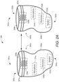
- Figures 1A and 1B illustrate various components of a representative hearing device arrangement in accordance with any of the embodiments disclosed herein.
- Figures 1A and 1B illustrate first and second hearing devices 100A and 100B configured to be supported at, by, in or on left and right ears of a wearer during use.
- a single hearing device 100A or 100B can be supported at, by, in or on the left or right ear of a wearer during use.
- the first and second hearing devices 100A and 100B include the same functional components. It is understood that the first and second hearing devices 100A and 100B can include different functional components.
- the first and second hearing devices 100A and 100B can be representative of any of the hearing devices disclosed herein.
- the first and second hearing devices 100A and 100B include an enclosure 101 configured for placement, for example, over or on the ear, entirely or partially within the external ear canal (e.g., between the pinna and ear drum) or behind the ear.
- a processor 102 Disposed within the enclosure 101 is a processor 102 which incorporates or is coupled to memory circuitry.
- the processor 102 can include or be implemented as a multi-core processor, a digital signal processor (DSP), an audio processor or a combination of these processors.
- the processor 102 may be implemented in a variety of different ways, such as with a mixture of discrete analog and digital components that include a processor configured to execute programmed instructions contained in a processor-readable storage medium (e.g., solid-state memory, e.g., Flash).
- a speaker or receiver 110 is coupled to an amplifier (not shown) and the processor 102. The speaker or receiver 110 is configured to generate sound which is communicated to the wearer's ear.
- the battery/antenna module 105 is included within the enclosure 101.
- the battery/antenna module 105 comprises a battery 106 encompassed by an antenna 108.
- the battery 106 is coupled to power management circuitry and provides power to the various components of the hearing devices 100A and 100B.
- the battery 106 is preferably a rechargeable battery, such as a lithium-ion battery or a lithium polymer battery. Other battery technologies are contemplated.
- the battery 106 can be implemented as a rechargeable supercapacitor power source, which incorporates one or more supercapacitors (e.g., coaxial fiber supercapacitors).
- the electronics of the hearing devices 100A and 100B can incorporate wireless charging circuitry 109.
- the wireless charging circuitry 109 is configured to cooperate with an external wireless charging station 120 to wirelessly charge the battery 106 of the battery/antenna module 105.
- the wireless charging station 120 uses an induction coil to create an alternating electromagnetic field which is transmitted to the wireless charging circuitry 109 within the enclosure 101. In response to the electromagnetic field, current is induced in an induction coil within the wireless charging circuitry 109 which charges the battery 106.
- the wireless charging circuitry 109 and wireless charging station 120 are configured to implement inductive charging in accordance with the Qi open interface standard developed by the Wireless Power Consortium.
- the processor 102 is coupled to a wireless transceiver 104 (also referred to herein as a radio), such as a BLE transceiver.
- the wireless transceiver 104 is operably coupled to the antenna 108 of the battery/antenna module 105 and configured for transmitting and receiving radio signals.
- the wireless transceiver 104 and antenna 108 can be configured to enable ear-to-ear communication between the two hearing devices 100A and 100B, as well as communications with an external device (e.g., a smartphone or a digital music player).
- the antenna 108 is preferably vertically polarized, which provides for reliable ear-to-ear communication since the vertically polarized antenna 108 efficiently couples with creeping waves.
- the antenna 108 is implemented as a helical antenna.
- the battery 106 has a metal (e.g., stainless steel) exterior, and an electrically insulating material is disposed between the battery 106 and the antenna 108.
- the battery 106 is encased or otherwise sealed within plastic or other electrically insulating material.
- the battery 106 can be a rechargeable battery (e.g., lithium-ion cell), and the encasement material provided over the battery 106 protects against battery leakage.
- the antenna 108 may include or exclude a protective coating, such as an electrically insulating material (e.g., polyimide).
- the electrically insulating material disposed on, covering, or encapsulating the battery 106 provides support for the antenna 108.
- the material covering the battery 106 can include a support arrangement (e.g., a thread, channel or groove arrangement) configured to support the antenna 108 on the battery 106.
- the antenna 108 is implemented as a flexible printed wire antenna which is affixed (e.g., via an adhesive) to the battery 106.
- electrically insulating layer (e.g., polyimide) of the flexible printed wire antenna serves as an electrical insulator between the antenna 108 and the battery 106.
- Wrapping the helical antenna 108 around the battery 106 to form an integrated battery/antenna module 105 makes the antenna 108 much more robust and stable compared to conventional wire and flexible antennas incorporated in a hearing device.
- the integrated battery/antenna configuration mitigates unexpected coupling effects with other metal components of the hearing device, and reduces the degree of uncertainty during the assembly.
- the hearing devices 100A and 100B include a microphone 112 mounted on or inside the enclosure 101.
- the microphone 112 may be a single microphone or multiple microphones, such as a microphone array.
- the microphone 112 can be coupled to a preamplifier (not shown), the output of which is coupled to the processor 102.
- the microphone 112 receives sound waves from the environment and converts the sound into an input signal.
- the input signal is amplified by the preamplifier and sampled and digitized by an analog-to-digital converter of the processor 102, resulting in a digitized input signal.
- the processor 102 e.g., DSP circuitry
- the processor 102 is configured to process the digitized input signal into an output signal in a manner that compensates for the wearer's hearing loss.
- the wireless transceiver 104 may produce a second input signal for the DSP circuitry of the processor 102 that may be combined with the input signal produced by the microphone 112 or used in place thereof.
- the processor 102 can be configured to process the digitized input signal into an output signal in a manner that is tailored or optimized for the wearer (e.g., based on wearer preferences).
- the output signal is then passed to an audio output stage that drives the speaker or receiver 110, which converts the output signal into an audio output.
- Some embodiments are directed to a custom hearing aid, such as an ITC, CIC, or IIC hearing aid.
- a custom hearing aid which includes a wireless transceiver and an antenna arrangement configured to operate in the 2.4 GHz ISM frequency band or other applicable communication band (referred to as the "Bluetooth ® band" herein).
- Bluetooth ® band the 2.4 GHz ISM frequency band or other applicable communication band
- creating a robust antenna arrangement for a 2.4 GHz custom hearing aid represents a significant engineering challenge.
- a custom hearing aid is severely limited in space, and the antenna arrangement is in close proximity to other electrical components, both of which impacts antenna performance.
- a high performance antenna 108 e.g., high antenna radiation efficiency and/or wide bandwidth
- Embodiments of the disclosure are directed to an integrated battery/antenna module having a compact form factor and which incorporates a high performance helical antenna.
- Figures 2A and 2B illustrate a custom hearing aid system which incorporates an integrated battery/antenna module in accordance with any of the embodiments disclosed herein.
- the hearing aid system 200 shown in Figures 2A and 2B includes two hearing devices, e.g., left 201a and right 201b side hearing devices, configured to wirelessly communicate with each other and external devices and systems.
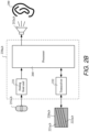
- Figure 2A conceptually illustrates functional blocks of the hearing devices 201a, 201b.
- the position of the functional blocks in Figure 2A does not necessarily indicate actual locations of components that implement these functional blocks within the hearing devices 201a, 201b.
- Figure 2B is a block diagram of components that may be disposed in and/or at least partially within the enclosure 205a, 205b of the hearing device 201a, 201b.
- Each hearing device 201a, 201b includes a physical enclosure 205a, 205b that encloses an internal volume.
- the enclosure 205a, 205b is configured for at least partial insertion within the wearer's ear canal.
- the enclosure 205a, 205b includes an external side 202a, 202b that faces away from the wearer and an internal side 203a, 203b that is inserted in the ear canal.
- the enclosure 205a, 205b comprises a shell 206a, 206b and can include a faceplate 207a, 207b.
- the shell 206a, 206b typically has a shape that is customized to the shape of a particular wearer's ear canal.
- a battery/antenna module 220a, 220b is disposed within the shell 206a, 206b.
- the battery/antenna module 220a, 220b comprises an antenna 222a, 222b that partially or completely encompasses a battery 221a, 221b.
- the battery/antenna module 220a, 220b can also comprise electrically insulating material disposed between the antenna 222a, 222b and the battery 221a, 221b.
- the antenna 222a, 222b is wrapped around the battery 221a, 221b to define a highly compact and space-efficient component of the hearing device 201a, 201b.
- the battery/antenna module 220a, 220b is mounted on the faceplate 207a, 207b.
- the battery/antenna module 220a, 220b is implemented as a non-removable component of the hearing device 201a, 201b
- the battery 221a, 221b is a rechargeable battery.
- the faceplate 207a, 207b may include a door 208a, 208b or drawer disposed near the external side 202a, 202b of the enclosure 205a, 205b and configured to allow the battery/antenna module 220a, 220b to be inserted into and removed from the enclosure 205a, 205b.
- the battery 221a, 221b is typically a conventional battery (e.g., non-rechargeable), but may alternatively be a rechargeable battery.
- the battery 221a, 221b of the battery/antenna module 220a, 220b powers electronic circuitry 230a, 230b which is also disposed within the shell 206a, 206b.
- the hearing device 201a, 201b may include one or more microphones 251a, 251b configured to pick up acoustic signals and to transduce the acoustic signals into microphone electrical signals.
- the electrical signals generated by the microphones 251a, 251b may be conditioned by an analog front end 231 (see Figure 2B ) by filtering, amplifying and/or converting the microphone electrical signals from analog to digital signals so that the digital signals can be further processed and/or analyzed by the processor 260.
- the processor 260 may perform signal processing and/or control various tasks of the hearing device 201a, 201b.
- the processor 260 comprises a DSP that may include additional computational processing units operating in a multi-core architecture.
- the processor 260 is configured to control wireless communication between the hearing devices 201a, 201b and/or an external accessory device (e.g., a smartphone, a digital music player) via the antenna 222a, 222b.
- the wireless communication may include, for example, audio streaming data and/or control signals.
- the electronic circuitry 230a, 230b of the hearing device 201a, 201b includes a transceiver 232 operably coupled to the antenna 222a, 222b.
- a matching network is coupled between the antenna 222a, 222b and the transceiver 232.
- the antenna 222a, 222b is configured as a self-resonant antenna, in which case no matching network or only a simplified matching network is needed.
- the transceiver 232 has a receiver portion that receives communication signals from the antenna 222a, 222b, demodulates the communication signals, and transfers the signals to the processor 260 for further processing.
- the transceiver 232 also includes a transmitter portion that modulates output signals from the processor 260 for transmission via the antenna 222a, 222b. Electrical signals from the microphone 251a, 251b and/or wireless communication received via the antenna 222a, 222b may be processed by the processor 260 and converted to acoustic signals played to the wearer's ear 299 via a speaker or receiver 252a, 252b.
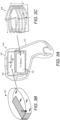
- FIG 3A illustrates a custom hearing aid 300 having a custom-shaped ITC shell 302 within which are housed a conventional arrangement of a separate battery 304 (e.g., a 312 battery) and a separate antenna 306, such as a PIFA shown in Figure 3B .
- the antenna 306 takes up an appreciable amount of space within the shell 302.
- the antenna 306 sits above the battery 304 and below a faceplate 307 of the hearing aid 300.
- the separate battery 304 and separate antenna 306 can have a total z-direction thickness (height) in excess of 6.2 mm.
- the custom hearing aid 300 or other hearing device can effectively eliminate the space dedicated to a separate antenna 306 within the device housing 302 by incorporating an integrated battery/antenna module 308 of the present disclosure, such as that shown in Figure 3C .
- the battery/antenna module 308 can occupy about the same space allocated for the battery 304 alone.
- the helical antenna can have a diameter from about 8 to 10 mm and a height from about 4 to 6 mm.
- the battery/antenna module 308 can have a total z-direction thickness (height) of about 5 mm.
- the battery/antenna module 308 can have a radius of about 5 mm (diameter of 10 mm). Given that space is very limited in a custom form factor device, incorporating the battery/antenna module 308 in a custom or other small form factor device provides for a significant reduction in the overall size of the device.
- the antenna of an integrated battery/antenna module can be implemented in accordance with electrically small antenna theory.
- An antenna is considered to be an electrically small antenna as a function of its occupied volume or overall size relative to the wavelength of a signal or band of signals the antenna is intended to receive and/or transmit.
- An electrically small antenna is one that ka ⁇ 0.5, where k is the free space wavenumber (2 ⁇ / ⁇ ), and a is the radius of an imaginary sphere which circumscribes its maximum dimensions. As the antenna size decreases, undesired strong coupling effects occur. These include, but are not limited to, a narrow bandwidth or high Q, poor impedance matching, low radiation efficiency, etc.
- any electrically small antenna can be tuned to be impedance matched at a single frequency using an external matching network with reactive components.
- the loss resistance in the matching components may decrease the overall efficiency.
- the antenna can be self-tuned to be impedance matched using a number of techniques, which is often more efficient than using an external matching network. This also reduces the costs of the matching components.
- the lower bound of the Q is determined by the antenna radiation efficiency and its overall size relative to the wavelength. That is, the Q is proportional to the radiation efficiency and inversely proportional to ka, according to the Wheeler-Chu limit theory. As is well understood, the Q and matched bandwidth are inversely related. Therefore, the bandwidth of the antenna will not be greater than the predicted inverse Q, the fundamental limit. In other words, no electrically small antenna will have a Q that is less than the lower bound.
- the antenna of an integrated battery/antenna module is implemented as a helical wire antenna based on electrically small antenna theory.
- the optimized bandwidth of an antenna is determined by the antenna radiation efficiency and its size to the wavelength.
- the relationship between the bandwidth B, wavenumber k, size a, and radiation efficiency ⁇ is as follows: Therefore, at a certain operating frequency, the size of the antenna can only be reduced at the expense of the bandwidth or efficiency.
- the best antenna performance can be achieved if the geometry aspect ratio is close to unity, and if the fields inside the antenna fill the minimum size which encloses the sphere with the greatest uniformity possible.
- the maximum dimension of the PIFA is 9.95 mm in the context of the custom ITC hearing aid shown in Figure 3A . Therefore, a ⁇ 5 mm.
- the PIFA shape only occupies a limited portion of the imaginary sphere with radius of 5 mm.
- the PIFA does not utilize the whole imaginary sphere volume.
- the bandwidth of the PIFA is narrower than the fundamental limit.
- the PIFA uses a high dielectric material as the substrate, which degrades the radiation efficiency. This is also a reason why a patch antenna usually has lower efficiency than a wire antenna.
- the helical antenna of an integrated battery/antenna module 308 attempts to occupy the battery module (cylinder) volume as much as possible.
- the helical antenna uses a low dielectric substrate as the holding structure, which can be made relatively thin so the efficiency will not degrade significantly from the dielectric loss.
- the helical antenna can be designed to approach the electrically small antenna limit, that is, by utilizing the whole volume of the battery, to gain a relative wider bandwidth, lower Q, and higher radiation efficiency.
- the helical antenna can be self-resonant around 2.5 GHz, and requires no or only minimal impedance matching effort for operation in the Bluetooth ® frequency band.
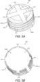
- FIGs 4A and 4B show an integrated battery/antenna module comprising a helical antenna in accordance with any of the embodiments disclosed herein.
- the antenna of the battery/antenna module can be implemented in accordance with electrically small antenna theory.
- the battery/antenna module 400 shown on Figure 4A includes a helical antenna 402 wrapped around a battery 404.
- the helical antenna 402 includes a ground plane 408 and a radiating arm arrangement 406.
- the battery 404 is situated on the ground plane 408.
- electrically insulating material is disposed between the battery 404 and the helical antenna 402 (see, e.g., Figures 5A, 5B , and 6 ).
- electrically insulating material is disposed between the battery 404 and the radiating arm arrangement 406, and between the battery 404 and the ground plane 408.
- the radiating arm arrangement 406 shown in Figure 4A includes a plurality of radiating arms that collectively wrap around the battery 404 in a spiral configuration.
- the radiating arm arrangement 406 includes four radiating arms 406a-406d.
- Each of the radiating arms 406a-406d has a first end 407 and an opposing second end 409.
- the first ends 407 of the radiating arms 406a-406d are electrically connected together, such as by use of a radiating arm connector 410 situated above the battery 404.
- the second ends 409 of at least one or more (or some) of the radiating arms 406a-406d (e.g., three of the four radiating arms) are electrically coupled to the ground plane 408.
- the second end 409 of at least one of the radiating arms 406a-406d is connected to a feed line, which is coupled to a radio frequency transceiver of the hearing device.
- the radiating arms 406a-406d are radially offset from one another.
- the four radiating arms 406a-406d are radially offset from one another by 90 degrees.
- radiating arm 406b is radially offset from radiating arm 406a by 90 degrees.
- Radiating arm 406c is radially offset from radiating arm 406b by 90 degrees.
- Radiating arm 406d is radially offset from radiating arm 406c by 90 degrees.
- each of the radiating arms 406a-406d preferably has a length electrically equivalent to about a quarter of a wavelength of a signal having a frequency falling within a specified frequency band, such as a Bluetooth ® band.
- Provision of radiating arms 406a-406d having a length electrically equivalent to about a quarter of the wavelength facilitates the implementation of a self-resonant (self-matched) helical antenna 402, in which the inductive reactance and the capacitive reactance of the helical antenna 402 are cancelled without the need of a matching network.
- the radiating arm arrangement 406 shown in Figure 4A includes four radiating arms 406a-406d that collectively wrap around the battery 404 in a spiral configuration. It is understood that a radiating arm arrangement of the present disclosure can include more or fewer than four radiating arms. For example, a radiating arm arrangement according to any of the embodiments disclosed herein can incorporate N radiating arms, where N can equal one, two, three, four, five, six, seven or eight radiating arms, for example.
- a 312 hearing aid battery has a quasi-cylindrical shape with a radius dimension of 3.8 mm and a height dimension of 3.6 mm.
- the space in the hearing device allocated for the battery can instead be used to accommodate an integrated battery/antenna module, particularly in view of its unique cylinder-liked shape.
- an imaginary cylinder can be made to accommodate the battery, though the imaginary sphere is an ideal one.
- the helical antenna 402 of the battery/antenna module 400 shown in Figure 4A can be designed from a single radiating arm 406a, one turn helix wire first, which is shown in Figure 4B .
- the helix wire 406a can be considered a meandered wire monopole.
- the total helix wire length is approximately a quarter wavelength, as previously discussed.
- the helical antenna 402 is then folded by three other arms 406b,c,d, each of which is radially offset by 90 degrees of separation.
- the top of the helical wire arrangement 406 is connected as a crisscross section via radiating arm connector 410.
- the folded technique provides for a helical antenna 402 which is self-matched at the resonant frequency.
- the helical antenna 402 and encompassed battery 404 are placed on a 5 mm x 5 mm ground plane 408 in this illustrative example.
- the feed can be located at the bottom of one radiating arm, while the other three radiating arms are connected to the ground plane 408.
- an electrically insulating material is disposed between the battery 404 and the helical antenna 402.
- Figures 5A and 5B show an integrated battery/antenna module comprising a helical antenna in accordance with any of the embodiments disclosed herein.
- Figures 5A and 5B are top and bottom perspective views of a battery/antenna module 500, respectively.
- the battery/antenna module 500 includes a helical antenna 502 wrapped around a battery 504. Wrapping the helical antenna 502 around the battery 504 to form an integrated battery/antenna module 500 makes the antenna 502 much more mechanically robust and stable compared to conventional wire and flexible antennas incorporated in hearing devices.
- the battery 504 has a sidewall having a generally cylindrical shape enclosed by top and bottom planar end surfaces 504a, 504b. It is understood that the battery 504 may have a different shape or cross-section, such as a substantially oval, square or rectangular shape or cross-section.
- the antenna 502 can have a shape that conforms to the battery shape, such as by having wires or traces forming a meandered, oval, square, rectangular, spherical, or conical shape (or any combination of these shapes). Electrically insulating material 515 is disposed between the battery 504 and the helical antenna 502.
- All or a portion of the battery 504 can be encased in plastic, a ceramic-based high dielectric constant material, or other electrically insulating material 515.
- the electrically insulating material 515 can conform to the shape of the battery 504 or have a shape differing from that of the battery 504.
- the electrically insulating material 515 can have a shape that dictates the shape of the antenna 502, irrespective of the shape of the battery 504.
- the electrically insulating material 515 forms a cap or sleeve which covers all or a portion of the battery 504.
- the cap or sleeve can be a 3D-printed structure, and the printing material can be VisiJet M3 Crystal material available from 3D Systems, Inc.
- electrically insulating material 515 is disposed between electrically conductive surfaces of the battery 504 and electrically conductive surfaces of the helical antenna 502.
- the helical antenna 502 includes a ground plane 508 adjacent the bottom planar end surface 504b of the battery 504, a radiating arm connector 510 (e.g., crisscross section) adjacent the top planar end surface 504a of the battery 504, and a radiating arm arrangement 506 extending between the ground plane 508 and the radiating arm connector 510.
- the radiating arm arrangement 506 includes a plurality of radiating arms that wrap around the battery 504 in a spiral configuration. As shown, the radiating arm arrangement 506 includes four radiating arms 506a-506d. Each of the radiating arms 506a-506d has a first end 507 and an opposing second end 509.
- the first ends 507 of the radiating arms 506a-506d are electrically connected together by the radiating arm connector 510.
- the second ends 509 of at least one or more (or some) (e.g., three) of the radiating arms 506a-506d are electrically coupled to the ground plane 508.
- the second end 509 of at least one of the radiating arms 506a-506d is configured to be electrically coupled to a feed line of a radio transceiver.
- an integrated battery/antenna module can incorporate a helical wire antenna.
- Figure 6 shows a cross-section of a battery/antenna module 600 incorporating a helical wire antenna 606 in accordance with any of the embodiments disclosed herein.
- the battery/antenna module 600 includes a battery 600 having a top planar surface 604a, an opposing bottom planar surface 604b, and a sidewall 605.
- the battery 604 has a generally cylindrical shape, but can have other shapes as previously described.
- Disposed on the sidewall 605 of the battery 604 is electrically insulating material 607.
- the electrically insulating material 607 represents a pre-fabricated cap which covers at least the sidewall 605 of the battery 604.
- electrically insulating material 607 e.g., the cap
- electrically insulating material 607 also covers the top and bottom planar surfaces 604a, 604b (see, e.g., Figures 5A and 5B ).
- the electrically insulating material 607 defines a cap configured to support the helical wire antenna 606. More particularly, the cap 607 includes a support arrangement configured to receive and capture one or more wires 610 of the helical wire antenna 606.
- the cap 607 can include individual threads 608 (e.g., grooves, channels) configured for receiving and capturing individual wires 610 of the helical wire antenna 606.
- the cap 607 can include four separate threads 608 configured to receive and capture four individual wires 610 of the helical wire antenna 606.
- the cap 607 incorporates C-shaped grooves 608 configured to receive and capture round wires 610.
- electrically insulating material 707 e.g., formed as a cap
- electrically insulating material 707 covering a battery can incorporate a polygonal-shaped (e.g., rectangle or square) thread, grooves or channel 708 configured to receive a polygonal-shaped (e.g., rectangle or square) wire 710.
- an integrated battery/antenna module can incorporate a flexible printed wire antenna.
- Figure 8 shows a cross-section of a battery/antenna module 800 incorporating a flexible printed wire antenna 806 wrapped around a sidewall 805 of a battery 804.
- the flexible printed wire antenna 806 is shown mounted to the sidewall 805 of the battery 804 via an adhesive 810.
- the flexible printed wire antenna 806 can incorporate an electrically conductive trace pattern encased in electrically insulating material.
- the trace pattern can include one or multiple traces (e.g., four traces) that form a helical trace configuration (see, e.g., Figures 4A-4B and 5A-5B ).
- the flexible printed wire antenna 806 can be implemented as a multiple-layer structure comprising a plurality of printed conductive traces (e.g., copper) encased by electrically insulating films, such as polyimide or polyester films.
- the battery 804 need not be covered by electrically insulating material since the flexible printed wire antenna 806 includes at least one layer of electrically insulating material as an outer protective film.
- the flexible printed wire antenna 806 can incorporate a ground plane, which can be situated adjacent a bottom planar end surface 804b of the battery 804, and further incorporate a trace connector arrangement (e.g., a crisscross connector) situated adjacent a top planar end surface 804a of the battery 804.
- the flexible printed wire antenna 806 can include one or a number of conductive traces (e.g., four traces) which are electrically connected to the ground plane, connector arrangement, and feedline in a manner previously described.
- Simulations were performed on a homogenous phantom head using a battery/antenna module having a helical antenna.
- the battery/antenna module (a helical antenna with battery inserted within the antenna) was placed in the phantom's ear canal.
- the simulated antenna reflection coefficient (S11) vs. frequency is plotted as curve 902 in Figure 9 . As shown in Figure 9 , the antenna resonant frequency is shifted to the higher range of the Bluetooth ® band (around 2.65 GHz) in the simulations.
- Figure 9 also shows S11 vs. frequency plotted as curve 904 derived from on-head measurement using a prototype battery/antenna module having a helical antenna.
- the prototype battery/antenna module comprised a helical antenna placed in an ITE shell, with a 312-dummy battery placed inside the antenna.
- a flexible circuit and receiver were placed inside the shell near the helical antenna to mimic the entire system.
- the antenna input impedance was measured using a Keysight N5230C Vector Network Analyzer.
- the measured S11 vs. frequency results are plotted as curve 904 in Figure 9 . It can be seen that the helical antenna achieves a very good impedance match around 2.54 GHz.
- the -6-dB bandwidth is 140 MHz (2.48 GHz - 2.62 GHz).
- a similar measurement was performed on a PIFA (see, e.g., Figure 3B ) within an ITE shell on a phantom head.
- the PIFA demonstrated a poor impedance match over the entire Bluetooth ® frequency band.
- the lowest S11 for the PIFA was -2.56 dB at 2.32 GHz, which would require a significant impedance matching effort at the desired frequency band.
- the helical antenna in contrast, requires no or only minimal matching effort since it has a wide bandwidth around 2.54 GHz.
- TRP Total radiated power
- the helical antenna was not fully optimized under the active environment (e.g., with radio, filter, transmission line etc.), the helical antenna it is expected to have a higher TRP once it is tuned with the circuit. Given the construction of the helical antenna under evaluation, the helical antenna achieved a good result, comparable to that of the tuned PIFA.
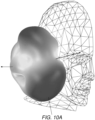
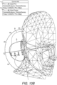
- Figures 10A and 10B show the radiation pattern of the helical antenna positioned on the head and operating at 2.44 GHz.
- the darker coloring indicates stronger electric field strength.
- the helical antenna is mainly vertically polarized when placed on the head. More specifically, the helical antenna generates an electric field having a direction of propagation substantially parallel around the wearer's head, and generates an electric field polarization substantially normal to the wearer's head. This is particularly beneficial to establishing an ear-to-ear communication link, since the vertically polarized antenna couples the creeping wave much more efficiently.
- the peak directivity at 2.44 GHz was 4.458 dB and radiation efficiency was -6.96 dB. The radiation efficiency is high compared to other 2.4 GHz custom hearing device antennas.
- a helical antenna of the present disclosure is generally dependent on a number of factors, including the space available in a particular ear-worn electronic device, the particular antenna performance requirements, and the size/shape of the battery which is encompassed by the helical antenna. Due to the performance benefit and small size, an integrated battery/antenna module of the present disclosure can be incorporated in devices beyond ear-worn electronic devices where device size significantly limits antenna size.
- Other devices e.g., body-worn electronic devices
- that can incorporate an integrated battery/antenna module of the present disclosure include, but are not limited to, fitness and/or health monitoring watches or other wrist worn or hand-held objects, e.g., Apple Watch ® , Fitbit ® , cell phones, smartphones, handheld radios, medical implants, hearing aid accessories, wireless capable helmets (e.g., used in professional football), and wireless headsets/headphones (e.g., virtual reality headsets).
- Each of these devices is represented by the system block diagram of Figure 1A or 1B , with the components of Figures 1A and 1B varying depending on the particular device implementation.
Landscapes
- Engineering & Computer Science (AREA)
- Physics & Mathematics (AREA)
- Acoustics & Sound (AREA)
- Signal Processing (AREA)
- Health & Medical Sciences (AREA)
- General Health & Medical Sciences (AREA)
- Neurosurgery (AREA)
- Otolaryngology (AREA)
- Computer Networks & Wireless Communication (AREA)
- Support Of Aerials (AREA)
- Battery Mounting, Suspending (AREA)
- Headphones And Earphones (AREA)
Claims (14)
- Im Ohr getragene elektronische Vorrichtung, die dazu konfiguriert ist, von einem Träger getragen zu werden, umfassend:ein Gehäuse (302), das dazu konfiguriert ist, an, durch, in oder auf dem Ohr des Trägers gestützt zu werden,einen in dem Gehäuse (302) angeordneten Prozessor (102, 206);einen Lautsprecher oder einen Empfänger (110, 252a, 252b), der betriebsfähig mit dem Prozessor (102, 206) gekoppelt ist;einen Hochfrequenz-Sendeempfänger (104), der in dem Gehäuse (302) angeordnet und betriebsfähig mit dem Prozessor (102, 206) gekoppelt ist; undein Batterieantennenmodul (105, 220a, 220b, 308, 400, 500, 600, 800), das in dem Gehäuse (302) angeordnet ist und Folgendes umfasst:eine Batterie (106, 221a, 221b, 304, 404, 504, 604, 804); undeine Helixantenne (108, 402, 502), die um die Batterie (106, 221a, 221b, 304, 404, 504, 604, 804) gewickelt und betriebsfähig mit dem Sendeempfänger (104) gekoppelt ist; undelektrisch isolierendes Material (515, 607, 707), das zwischen der Helixantenne (108, 402, 502) und der Batterie (106, 221a, 221b, 304, 404, 504, 604, 804) angeordnet ist,wobei die im Ohr getragene elektronische Vorrichtung dadurch gekennzeichnet ist, dassdie Helixantenne (108, 402, 502) eine Erdungsebene (408, 508) umfasst und die Batterie (106, 221a, 221b, 304, 404, 504, 604, 804) auf der Erdungsebene (408, 508) gelegen ist.
- Vorrichtung nach Anspruch 1, wobei:das elektrisch isolierende Material (515, 607, 707) als eine Kappe konfiguriert ist, die die Batterie (106, 221a, 221b, 304, 404, 504, 604, 804) zumindest teilweise abdeckt; unddie Kappe eine Stützanordnung umfasst, die dazu konfiguriert ist, die Helixantenne (108, 402, 502) an der Batterie (106, 221a, 221b, 304, 404, 504, 604, 804) zu stützen.
- Vorrichtung nach Anspruch 2, wobei die Stützanordnung der Kappe eine Gewindeanordnung umfasst, die dazu konfiguriert ist, die Helixantenne (108, 402, 502) haltend zu stützen.
- Vorrichtung nach einem vorstehenden Anspruch, wobei:die Helixantenne (108, 402, 502) eine flexible, gedruckte Drahtantenne umfasst, die an der Batterie (106, 221a, 221b, 304, 404, 504, 604, 804) befestigt ist; unddas elektrisch isolierende Material (515, 607, 707) eine elektrisch isolierende Schicht der flexiblen, gedruckten Drahtantenne definiert.
- Vorrichtung nach einem vorstehenden Anspruch, wobei die Helixantenne (108, 402, 502) eine Vielzahl von Strahlungsarmen (406a-d, 506a-d) umfasst, die voneinander beabstandet sind.
- Vorrichtung nach Anspruch 5, wobei die Strahlungsarme (406a-d, 506a-d) radial voneinander versetzt sind.
- Vorrichtung nach den Ansprüchen 5 oder 6, wobei:jeder der Strahlungsarme (406a-d, 506a-d) ein erstes Ende und ein zweites Ende umfasst;die ersten Enden elektrisch miteinander verbunden sind;mindestens eines oder mehrere der zweiten Enden mit einer Erdungsebene der Helixantenne (108, 402, 502) gekoppelt sind; undein zweites Ende von mindestens einem der Strahlungsarme (406a-d, 506a-d) mit einer Zuführleitung der Helixantenne (108, 402, 502) gekoppelt ist.
- Vorrichtung nach einem vorstehenden Anspruch, wobei:die Helixantenne (108, 402, 502) vier Strahlungsarme (406a-d, 506a-d) umfasst, die radial um 90 Grad voneinander versetzt sind; undjeder der Strahlungsarme (406a-d, 506a-d) eine Länge aufweist, die zu etwa einem Viertel einer Wellenlänge eines Signals, das eine Frequenz aufweist, die in ein spezifiziertes Frequenzband fällt, elektrisch äquivalent ist.
- Vorrichtung nach einem vorstehenden Anspruch, wobei die Helixantenne (108, 402, 502) selbstresonant ist.
- Vorrichtung nach einem vorstehenden Anspruch, wobei, wenn die Vorrichtung an, bei, in oder auf dem Ohr des Trägers positioniert ist, die Helixantenne (108, 402, 502) dazu konfiguriert ist:ein elektrisches Feld zu erzeugen, das eine Ausbreitungsrichtung im Wesentlichen parallel zu dem Kopf des Trägers aufweist; undeine elektrische Feldpolarisation zu erzeugen, die im Wesentlichen normal zu dem Kopf des Trägers ist.
- Vorrichtung nach einem vorstehenden Anspruch, wobei die Helixantenne (108, 402, 502) und der Sendeempfänger dazu konfiguriert sind, innerhalb eines 2,4 GHz-ISM-Frequenzbands zu arbeiten.
- Vorrichtung nach einem vorstehenden Anspruch, wobei:die Helixantenne (108, 402, 502) weiter eine Vielzahl von Drähten umfasst, die um die Batterie (106, 221a, 221b, 304, 404, 504, 604, 804) gewickelt sind; unddie elektrisch isolierende Kappe dazu konfiguriert ist, die Drähte von der Batterie (106, 221a, 221b, 304, 404, 504, 604, 804) zu trennen, und eine Stützanordnung umfasst, die dazu konfiguriert ist, die Drähte in einer fixierten Position relativ zu der Batterie (106, 221a, 221b, 304, 404, 504, 604, 804) zu stützen.
- Vorrichtung nach einem vorstehenden Anspruch, wobei:die Kappe eine spiralförmige Gewindeanordnung umfasst; unddie Drähte mit der Gewindeanordnung aufgenommen werden.
- Vorrichtung nach einem vorstehenden Anspruch, wobei die Helixantenne (108, 402, 502) einen Durchmesser von etwa 8 bis 10 mm und eine Höhe von etwa 4 bis 6 mm aufweist.
Applications Claiming Priority (1)
| Application Number | Priority Date | Filing Date | Title |
|---|---|---|---|
| US16/285,667 US11140496B2 (en) | 2019-02-26 | 2019-02-26 | Ear-worn electronic device incorporating an integrated battery/antenna module |
Publications (3)
| Publication Number | Publication Date |
|---|---|
| EP3703386A2 EP3703386A2 (de) | 2020-09-02 |
| EP3703386A3 EP3703386A3 (de) | 2020-11-18 |
| EP3703386B1 true EP3703386B1 (de) | 2025-01-01 |
Family
ID=69740246
Family Applications (1)
| Application Number | Title | Priority Date | Filing Date |
|---|---|---|---|
| EP20159556.8A Active EP3703386B1 (de) | 2019-02-26 | 2020-02-26 | Am ohr getragene elektronische vorrichtung mit einem integrierten batterie-/antennenmodul |
Country Status (2)
| Country | Link |
|---|---|
| US (2) | US11140496B2 (de) |
| EP (1) | EP3703386B1 (de) |
Families Citing this family (5)
| Publication number | Priority date | Publication date | Assignee | Title |
|---|---|---|---|---|
| DE102020201479A1 (de) * | 2020-02-06 | 2021-08-12 | Sivantos Pte. Ltd. | Hörgerät |
| DE102020201480A1 (de) * | 2020-02-06 | 2021-08-12 | Sivantos Pte. Ltd. | Hörgerät |
| US11469489B2 (en) * | 2020-04-28 | 2022-10-11 | Bose Corporation | Antenna operable in single-ended and differential modes |
| DE102022203528A1 (de) | 2022-04-07 | 2023-10-12 | Sivantos Pte. Ltd. | Hörgerät, insbesondere In-dem-Ohr-Hörgerät |
| US12153729B2 (en) * | 2022-10-18 | 2024-11-26 | Snap Inc. | Head property detection in display-enabled wearable devices |
Citations (4)
| Publication number | Priority date | Publication date | Assignee | Title |
|---|---|---|---|---|
| US20100158295A1 (en) | 2008-12-19 | 2010-06-24 | Starkey Laboratories, Inc. | Antennas for custom fit hearing assistance devices |
| US20100202639A1 (en) | 2004-02-19 | 2010-08-12 | Christensen Kare T | Hearing aid with antenna for reception and transmission of electromagnetic signals |
| US20160205461A1 (en) | 2015-01-12 | 2016-07-14 | Qualcomm Technologies International, Ltd. | Antennas suitable for wireless earphones |
| WO2018182091A1 (ko) | 2017-03-31 | 2018-10-04 | 주식회사 아모텍 | 링형 안테나 및 이를 구비한 이어 모듈 |
Family Cites Families (17)
| Publication number | Priority date | Publication date | Assignee | Title |
|---|---|---|---|---|
| US6229499B1 (en) | 1999-11-05 | 2001-05-08 | Xm Satellite Radio, Inc. | Folded helix antenna design |
| US7292203B2 (en) | 2002-06-12 | 2007-11-06 | Thiss Technologies Pte Ltd. | Helix antenna |
| US7593538B2 (en) | 2005-03-28 | 2009-09-22 | Starkey Laboratories, Inc. | Antennas for hearing aids |
| US8369959B2 (en) | 2007-05-31 | 2013-02-05 | Cochlear Limited | Implantable medical device with integrated antenna system |
| US8259026B2 (en) | 2008-12-31 | 2012-09-04 | Motorola Mobility Llc | Counterpoise to mitigate near field radiation generated by wireless communication devices |
| WO2011016045A2 (en) | 2009-08-06 | 2011-02-10 | Indian Space Research Organisation Of Isro | Printed quasi-tapered tape helical array antenna |
| EP2763744B1 (de) | 2011-10-07 | 2015-09-23 | Advanced Bionics AG | Leitungskörper mit schläuchen von unterschiedlichem durchmesser für ein cochleaimplantat und ein verfahren zur herstellung eines solchen leitungskörpers |
| DE102012214469A1 (de) * | 2012-06-06 | 2013-12-12 | Siemens Aktiengesellschaft | Hörinstrumentsystem mit wiederaufladbarer Batterie |
| US9686621B2 (en) * | 2013-11-11 | 2017-06-20 | Gn Hearing A/S | Hearing aid with an antenna |
| EP3110175B1 (de) | 2015-06-24 | 2020-03-25 | Oticon A/s | Hörgerät mit in batterieschublade eingebetteter antenneneinheit |
| US9866282B2 (en) | 2015-08-29 | 2018-01-09 | Bragi GmbH | Magnetic induction antenna for use in a wearable device |
| US9972895B2 (en) * | 2015-08-29 | 2018-05-15 | Bragi GmbH | Antenna for use in a wearable device |
| US10440483B2 (en) | 2015-11-25 | 2019-10-08 | Gn Hearing A/S | Hearing aid with improved wireless communication |
| WO2017127758A1 (en) | 2016-01-20 | 2017-07-27 | Setpoint Medical Corporation | Implantable microstimulators and inductive charging systems |
| US10587943B2 (en) * | 2016-07-09 | 2020-03-10 | Bragi GmbH | Earpiece with wirelessly recharging battery |
| US10051388B2 (en) | 2016-09-21 | 2018-08-14 | Starkey Laboratories, Inc. | Radio frequency antenna for an in-the-ear hearing device |
| US10256529B2 (en) | 2016-11-15 | 2019-04-09 | Starkey Laboratories, Inc. | Hearing device incorporating conformal folded antenna |
-
2019
- 2019-02-26 US US16/285,667 patent/US11140496B2/en active Active
-
2020
- 2020-02-26 EP EP20159556.8A patent/EP3703386B1/de active Active
-
2021
- 2021-09-24 US US17/484,139 patent/US20220053274A1/en not_active Abandoned
Patent Citations (4)
| Publication number | Priority date | Publication date | Assignee | Title |
|---|---|---|---|---|
| US20100202639A1 (en) | 2004-02-19 | 2010-08-12 | Christensen Kare T | Hearing aid with antenna for reception and transmission of electromagnetic signals |
| US20100158295A1 (en) | 2008-12-19 | 2010-06-24 | Starkey Laboratories, Inc. | Antennas for custom fit hearing assistance devices |
| US20160205461A1 (en) | 2015-01-12 | 2016-07-14 | Qualcomm Technologies International, Ltd. | Antennas suitable for wireless earphones |
| WO2018182091A1 (ko) | 2017-03-31 | 2018-10-04 | 주식회사 아모텍 | 링형 안테나 및 이를 구비한 이어 모듈 |
Also Published As
| Publication number | Publication date |
|---|---|
| US20220053274A1 (en) | 2022-02-17 |
| US11140496B2 (en) | 2021-10-05 |
| EP3703386A3 (de) | 2020-11-18 |
| US20200275218A1 (en) | 2020-08-27 |
| EP3703386A2 (de) | 2020-09-02 |
Similar Documents
| Publication | Publication Date | Title |
|---|---|---|
| EP3703386B1 (de) | Am ohr getragene elektronische vorrichtung mit einem integrierten batterie-/antennenmodul | |
| EP3648478B1 (de) | Hörvorrichtung mit einer primärantenne in verbindung mit einer chipantenne | |
| CN106303871B (zh) | 包括天线单元的听力装置 | |
| US11122376B2 (en) | Ear-worn electronic device incorporating magnetically coupled feed for an antenna | |
| CN110177327B (zh) | 具有天线的助听器装置 | |
| EP3457718B1 (de) | Antenne, die in verbindung mit leitungen für einen audiowandlerverwendet wird | |
| EP2076065B2 (de) | Hörgerät und Verfahren zum drahtlosen Empfangen und/oder Senden von Daten | |
| CN105722000B (zh) | 听力装置 | |
| US11425512B2 (en) | Ear-worn electronic hearing device incorporating an antenna with cutouts | |
| US11355834B2 (en) | Ear-worn electronic device incorporating an antenna substrate comprising a dielectric gel or liquid | |
| CN113852900B (zh) | 一种听力设备 | |
| CN108289274B (zh) | 包括外部天线和内部寄生元件的听力设备 | |
| US12167200B2 (en) | Hearing device with shielding antenna | |
| US11902748B2 (en) | Ear-worn electronic hearing device incorporating an antenna with cutouts | |
| CN116939463A (zh) | 一种听力装置 |
Legal Events
| Date | Code | Title | Description |
|---|---|---|---|
| PUAI | Public reference made under article 153(3) epc to a published international application that has entered the european phase |
Free format text: ORIGINAL CODE: 0009012 |
|
| STAA | Information on the status of an ep patent application or granted ep patent |
Free format text: STATUS: THE APPLICATION HAS BEEN PUBLISHED |
|
| AK | Designated contracting states |
Kind code of ref document: A2 Designated state(s): AL AT BE BG CH CY CZ DE DK EE ES FI FR GB GR HR HU IE IS IT LI LT LU LV MC MK MT NL NO PL PT RO RS SE SI SK SM TR |
|
| AX | Request for extension of the european patent |
Extension state: BA ME |
|
| PUAL | Search report despatched |
Free format text: ORIGINAL CODE: 0009013 |
|
| AK | Designated contracting states |
Kind code of ref document: A3 Designated state(s): AL AT BE BG CH CY CZ DE DK EE ES FI FR GB GR HR HU IE IS IT LI LT LU LV MC MK MT NL NO PL PT RO RS SE SI SK SM TR |
|
| AX | Request for extension of the european patent |
Extension state: BA ME |
|
| RIC1 | Information provided on ipc code assigned before grant |
Ipc: H04R 25/00 20060101ALI20201012BHEP Ipc: H04R 1/10 20060101AFI20201012BHEP |
|
| STAA | Information on the status of an ep patent application or granted ep patent |
Free format text: STATUS: REQUEST FOR EXAMINATION WAS MADE |
|
| 17P | Request for examination filed |
Effective date: 20210518 |
|
| RBV | Designated contracting states (corrected) |
Designated state(s): AL AT BE BG CH CY CZ DE DK EE ES FI FR GB GR HR HU IE IS IT LI LT LU LV MC MK MT NL NO PL PT RO RS SE SI SK SM TR |
|
| STAA | Information on the status of an ep patent application or granted ep patent |
Free format text: STATUS: EXAMINATION IS IN PROGRESS |
|
| 17Q | First examination report despatched |
Effective date: 20220914 |
|
| GRAP | Despatch of communication of intention to grant a patent |
Free format text: ORIGINAL CODE: EPIDOSNIGR1 |
|
| STAA | Information on the status of an ep patent application or granted ep patent |
Free format text: STATUS: GRANT OF PATENT IS INTENDED |
|
| RIC1 | Information provided on ipc code assigned before grant |
Ipc: H01Q 1/36 20060101ALI20240824BHEP Ipc: H01Q 1/27 20060101ALI20240824BHEP Ipc: H04R 25/00 20060101ALI20240824BHEP Ipc: H04R 1/10 20060101AFI20240824BHEP |
|
| INTG | Intention to grant announced |
Effective date: 20240904 |
|
| GRAS | Grant fee paid |
Free format text: ORIGINAL CODE: EPIDOSNIGR3 |
|
| GRAA | (expected) grant |
Free format text: ORIGINAL CODE: 0009210 |
|
| STAA | Information on the status of an ep patent application or granted ep patent |
Free format text: STATUS: THE PATENT HAS BEEN GRANTED |
|
| P01 | Opt-out of the competence of the unified patent court (upc) registered |
Free format text: CASE NUMBER: APP_59685/2024 Effective date: 20241104 |
|
| AK | Designated contracting states |
Kind code of ref document: B1 Designated state(s): AL AT BE BG CH CY CZ DE DK EE ES FI FR GB GR HR HU IE IS IT LI LT LU LV MC MK MT NL NO PL PT RO RS SE SI SK SM TR |
|
| REG | Reference to a national code |
Ref country code: GB Ref legal event code: FG4D |
|
| REG | Reference to a national code |
Ref country code: CH Ref legal event code: EP |
|
| REG | Reference to a national code |
Ref country code: DE Ref legal event code: R096 Ref document number: 602020043913 Country of ref document: DE |
|
| REG | Reference to a national code |
Ref country code: IE Ref legal event code: FG4D |
|
| PGFP | Annual fee paid to national office [announced via postgrant information from national office to epo] |
Ref country code: DE Payment date: 20250214 Year of fee payment: 6 |
|
| PGFP | Annual fee paid to national office [announced via postgrant information from national office to epo] |
Ref country code: FR Payment date: 20250224 Year of fee payment: 6 |
|
| REG | Reference to a national code |
Ref country code: LT Ref legal event code: MG9D |
|
| REG | Reference to a national code |
Ref country code: NL Ref legal event code: MP Effective date: 20250101 |
|
| REG | Reference to a national code |
Ref country code: AT Ref legal event code: MK05 Ref document number: 1757528 Country of ref document: AT Kind code of ref document: T Effective date: 20250101 |
|
| PG25 | Lapsed in a contracting state [announced via postgrant information from national office to epo] |
Ref country code: NL Free format text: LAPSE BECAUSE OF FAILURE TO SUBMIT A TRANSLATION OF THE DESCRIPTION OR TO PAY THE FEE WITHIN THE PRESCRIBED TIME-LIMIT Effective date: 20250101 |
|
| PG25 | Lapsed in a contracting state [announced via postgrant information from national office to epo] |
Ref country code: FI Free format text: LAPSE BECAUSE OF FAILURE TO SUBMIT A TRANSLATION OF THE DESCRIPTION OR TO PAY THE FEE WITHIN THE PRESCRIBED TIME-LIMIT Effective date: 20250101 |
|
| PG25 | Lapsed in a contracting state [announced via postgrant information from national office to epo] |
Ref country code: PL Free format text: LAPSE BECAUSE OF FAILURE TO SUBMIT A TRANSLATION OF THE DESCRIPTION OR TO PAY THE FEE WITHIN THE PRESCRIBED TIME-LIMIT Effective date: 20250101 |
|
| PG25 | Lapsed in a contracting state [announced via postgrant information from national office to epo] |
Ref country code: ES Free format text: LAPSE BECAUSE OF FAILURE TO SUBMIT A TRANSLATION OF THE DESCRIPTION OR TO PAY THE FEE WITHIN THE PRESCRIBED TIME-LIMIT Effective date: 20250101 |
|
| PG25 | Lapsed in a contracting state [announced via postgrant information from national office to epo] |
Ref country code: IS Free format text: LAPSE BECAUSE OF FAILURE TO SUBMIT A TRANSLATION OF THE DESCRIPTION OR TO PAY THE FEE WITHIN THE PRESCRIBED TIME-LIMIT Effective date: 20250501 Ref country code: NO Free format text: LAPSE BECAUSE OF FAILURE TO SUBMIT A TRANSLATION OF THE DESCRIPTION OR TO PAY THE FEE WITHIN THE PRESCRIBED TIME-LIMIT Effective date: 20250401 |
|
| PG25 | Lapsed in a contracting state [announced via postgrant information from national office to epo] |
Ref country code: HR Free format text: LAPSE BECAUSE OF FAILURE TO SUBMIT A TRANSLATION OF THE DESCRIPTION OR TO PAY THE FEE WITHIN THE PRESCRIBED TIME-LIMIT Effective date: 20250101 |
|
| PG25 | Lapsed in a contracting state [announced via postgrant information from national office to epo] |
Ref country code: LV Free format text: LAPSE BECAUSE OF FAILURE TO SUBMIT A TRANSLATION OF THE DESCRIPTION OR TO PAY THE FEE WITHIN THE PRESCRIBED TIME-LIMIT Effective date: 20250101 Ref country code: PT Free format text: LAPSE BECAUSE OF FAILURE TO SUBMIT A TRANSLATION OF THE DESCRIPTION OR TO PAY THE FEE WITHIN THE PRESCRIBED TIME-LIMIT Effective date: 20250502 |
|
| PG25 | Lapsed in a contracting state [announced via postgrant information from national office to epo] |
Ref country code: BG Free format text: LAPSE BECAUSE OF FAILURE TO SUBMIT A TRANSLATION OF THE DESCRIPTION OR TO PAY THE FEE WITHIN THE PRESCRIBED TIME-LIMIT Effective date: 20250101 Ref country code: GR Free format text: LAPSE BECAUSE OF FAILURE TO SUBMIT A TRANSLATION OF THE DESCRIPTION OR TO PAY THE FEE WITHIN THE PRESCRIBED TIME-LIMIT Effective date: 20250402 |
|
| PG25 | Lapsed in a contracting state [announced via postgrant information from national office to epo] |
Ref country code: AT Free format text: LAPSE BECAUSE OF FAILURE TO SUBMIT A TRANSLATION OF THE DESCRIPTION OR TO PAY THE FEE WITHIN THE PRESCRIBED TIME-LIMIT Effective date: 20250101 |
|
| PG25 | Lapsed in a contracting state [announced via postgrant information from national office to epo] |
Ref country code: CZ Free format text: LAPSE BECAUSE OF FAILURE TO SUBMIT A TRANSLATION OF THE DESCRIPTION OR TO PAY THE FEE WITHIN THE PRESCRIBED TIME-LIMIT Effective date: 20250101 |
|
| PG25 | Lapsed in a contracting state [announced via postgrant information from national office to epo] |
Ref country code: SE Free format text: LAPSE BECAUSE OF FAILURE TO SUBMIT A TRANSLATION OF THE DESCRIPTION OR TO PAY THE FEE WITHIN THE PRESCRIBED TIME-LIMIT Effective date: 20250101 |
|
| REG | Reference to a national code |
Ref country code: CH Ref legal event code: PL |
|
| REG | Reference to a national code |
Ref country code: DE Ref legal event code: R026 Ref document number: 602020043913 Country of ref document: DE |
|
| PLBI | Opposition filed |
Free format text: ORIGINAL CODE: 0009260 |
|
| PG25 | Lapsed in a contracting state [announced via postgrant information from national office to epo] |
Ref country code: SM Free format text: LAPSE BECAUSE OF FAILURE TO SUBMIT A TRANSLATION OF THE DESCRIPTION OR TO PAY THE FEE WITHIN THE PRESCRIBED TIME-LIMIT Effective date: 20250101 |
|
| PG25 | Lapsed in a contracting state [announced via postgrant information from national office to epo] |
Ref country code: DK Free format text: LAPSE BECAUSE OF FAILURE TO SUBMIT A TRANSLATION OF THE DESCRIPTION OR TO PAY THE FEE WITHIN THE PRESCRIBED TIME-LIMIT Effective date: 20250101 |
|
| PG25 | Lapsed in a contracting state [announced via postgrant information from national office to epo] |
Ref country code: MC Free format text: LAPSE BECAUSE OF FAILURE TO SUBMIT A TRANSLATION OF THE DESCRIPTION OR TO PAY THE FEE WITHIN THE PRESCRIBED TIME-LIMIT Effective date: 20250101 |
|
| PG25 | Lapsed in a contracting state [announced via postgrant information from national office to epo] |
Ref country code: IT Free format text: LAPSE BECAUSE OF FAILURE TO SUBMIT A TRANSLATION OF THE DESCRIPTION OR TO PAY THE FEE WITHIN THE PRESCRIBED TIME-LIMIT Effective date: 20250101 Ref country code: LU Free format text: LAPSE BECAUSE OF NON-PAYMENT OF DUE FEES Effective date: 20250226 |
|
| PG25 | Lapsed in a contracting state [announced via postgrant information from national office to epo] |
Ref country code: CH Free format text: LAPSE BECAUSE OF NON-PAYMENT OF DUE FEES Effective date: 20250228 |
|
| PG25 | Lapsed in a contracting state [announced via postgrant information from national office to epo] |
Ref country code: EE Free format text: LAPSE BECAUSE OF FAILURE TO SUBMIT A TRANSLATION OF THE DESCRIPTION OR TO PAY THE FEE WITHIN THE PRESCRIBED TIME-LIMIT Effective date: 20250101 |
|
| PG25 | Lapsed in a contracting state [announced via postgrant information from national office to epo] |
Ref country code: RO Free format text: LAPSE BECAUSE OF FAILURE TO SUBMIT A TRANSLATION OF THE DESCRIPTION OR TO PAY THE FEE WITHIN THE PRESCRIBED TIME-LIMIT Effective date: 20250101 |
|
| PG25 | Lapsed in a contracting state [announced via postgrant information from national office to epo] |
Ref country code: SK Free format text: LAPSE BECAUSE OF FAILURE TO SUBMIT A TRANSLATION OF THE DESCRIPTION OR TO PAY THE FEE WITHIN THE PRESCRIBED TIME-LIMIT Effective date: 20250101 |
|
| 26 | Opposition filed |
Opponent name: OTICON A/S Effective date: 20251001 |
|
| REG | Reference to a national code |
Ref country code: BE Ref legal event code: MM Effective date: 20250228 |
|
| PLAX | Notice of opposition and request to file observation + time limit sent |
Free format text: ORIGINAL CODE: EPIDOSNOBS2 |
|
| GBPC | Gb: european patent ceased through non-payment of renewal fee |
Effective date: 20250401 |
|
| PG25 | Lapsed in a contracting state [announced via postgrant information from national office to epo] |
Ref country code: GB Free format text: LAPSE BECAUSE OF NON-PAYMENT OF DUE FEES Effective date: 20250401 |
|
| PG25 | Lapsed in a contracting state [announced via postgrant information from national office to epo] |
Ref country code: BE Free format text: LAPSE BECAUSE OF NON-PAYMENT OF DUE FEES Effective date: 20250228 |
|
| PG25 | Lapsed in a contracting state [announced via postgrant information from national office to epo] |
Ref country code: IE Free format text: LAPSE BECAUSE OF NON-PAYMENT OF DUE FEES Effective date: 20250226 |