EP3703267A1 - Agencement de commutateur - Google Patents
Agencement de commutateur Download PDFInfo
- Publication number
- EP3703267A1 EP3703267A1 EP19159726.9A EP19159726A EP3703267A1 EP 3703267 A1 EP3703267 A1 EP 3703267A1 EP 19159726 A EP19159726 A EP 19159726A EP 3703267 A1 EP3703267 A1 EP 3703267A1
- Authority
- EP
- European Patent Office
- Prior art keywords
- node
- switch
- receive
- transmit
- coupled
- Prior art date
- Legal status (The legal status is an assumption and is not a legal conclusion. Google has not performed a legal analysis and makes no representation as to the accuracy of the status listed.)
- Withdrawn
Links
- 239000004065 semiconductor Substances 0.000 claims abstract description 274
- 230000008878 coupling Effects 0.000 claims abstract description 48
- 238000010168 coupling process Methods 0.000 claims abstract description 48
- 238000005859 coupling reaction Methods 0.000 claims abstract description 48
- 239000003990 capacitor Substances 0.000 claims description 41
- 230000011664 signaling Effects 0.000 claims description 35
- 238000004891 communication Methods 0.000 claims description 17
- 238000000034 method Methods 0.000 claims description 15
- 230000005540 biological transmission Effects 0.000 claims description 14
- 230000000903 blocking effect Effects 0.000 claims description 7
- 238000012545 processing Methods 0.000 claims description 6
- 230000015572 biosynthetic process Effects 0.000 claims description 4
- 230000001052 transient effect Effects 0.000 description 3
- 230000003321 amplification Effects 0.000 description 2
- 230000007850 degeneration Effects 0.000 description 2
- 238000004519 manufacturing process Methods 0.000 description 2
- 239000000463 material Substances 0.000 description 2
- 238000012986 modification Methods 0.000 description 2
- 230000004048 modification Effects 0.000 description 2
- 238000003199 nucleic acid amplification method Methods 0.000 description 2
- 230000001419 dependent effect Effects 0.000 description 1
- 238000010586 diagram Methods 0.000 description 1
- 230000000694 effects Effects 0.000 description 1
- 238000003780 insertion Methods 0.000 description 1
- 230000037431 insertion Effects 0.000 description 1
- 230000003071 parasitic effect Effects 0.000 description 1
Images


Classifications
-
- H—ELECTRICITY
- H04—ELECTRIC COMMUNICATION TECHNIQUE
- H04B—TRANSMISSION
- H04B1/00—Details of transmission systems, not covered by a single one of groups H04B3/00 - H04B13/00; Details of transmission systems not characterised by the medium used for transmission
- H04B1/38—Transceivers, i.e. devices in which transmitter and receiver form a structural unit and in which at least one part is used for functions of transmitting and receiving
- H04B1/40—Circuits
- H04B1/44—Transmit/receive switching
- H04B1/48—Transmit/receive switching in circuits for connecting transmitter and receiver to a common transmission path, e.g. by energy of transmitter
-
- H—ELECTRICITY
- H03—ELECTRONIC CIRCUITRY
- H03K—PULSE TECHNIQUE
- H03K17/00—Electronic switching or gating, i.e. not by contact-making and –breaking
- H03K17/51—Electronic switching or gating, i.e. not by contact-making and –breaking characterised by the components used
- H03K17/56—Electronic switching or gating, i.e. not by contact-making and –breaking characterised by the components used by the use, as active elements, of semiconductor devices
- H03K17/567—Circuits characterised by the use of more than one type of semiconductor device, e.g. BIMOS, composite devices such as IGBT
-
- H—ELECTRICITY
- H03—ELECTRONIC CIRCUITRY
- H03H—IMPEDANCE NETWORKS, e.g. RESONANT CIRCUITS; RESONATORS
- H03H11/00—Networks using active elements
- H03H11/02—Multiple-port networks
- H03H11/28—Impedance matching networks
-
- H—ELECTRICITY
- H03—ELECTRONIC CIRCUITRY
- H03K—PULSE TECHNIQUE
- H03K17/00—Electronic switching or gating, i.e. not by contact-making and –breaking
- H03K17/002—Switching arrangements with several input- or output terminals
- H03K17/007—Switching arrangements with several input- or output terminals with several outputs only
-
- H—ELECTRICITY
- H04—ELECTRIC COMMUNICATION TECHNIQUE
- H04B—TRANSMISSION
- H04B1/00—Details of transmission systems, not covered by a single one of groups H04B3/00 - H04B13/00; Details of transmission systems not characterised by the medium used for transmission
- H04B1/38—Transceivers, i.e. devices in which transmitter and receiver form a structural unit and in which at least one part is used for functions of transmitting and receiving
- H04B1/40—Circuits
- H04B1/44—Transmit/receive switching
-
- H—ELECTRICITY
- H04—ELECTRIC COMMUNICATION TECHNIQUE
- H04L—TRANSMISSION OF DIGITAL INFORMATION, e.g. TELEGRAPHIC COMMUNICATION
- H04L5/00—Arrangements affording multiple use of the transmission path
- H04L5/14—Two-way operation using the same type of signal, i.e. duplex
- H04L5/16—Half-duplex systems; Simplex/duplex switching; Transmission of break signals non-automatically inverting the direction of transmission
Definitions
- the present disclosure relates to a switch arrangement.
- it relates to a switch arrangement for switching between a receive path and a transmit path of a transceiver. It also relates to a corresponding method and communication device.
- Communication devices such as half-duplex communication devices, may include a switch arrangement to provide for selection of either a receive path or a transmit path.
- the switch arrangement may be part of RF front-end circuitry of the communication device.
- a switch arrangement comprising:
- the third semiconductor switch in the first switch mode, may provide for coupling of the second branch with a reference voltage, which provides impedance mismatching between the transceiver node and the other of the transmit and receive nodes, and thereby allows for impedance matching over the first branch.
- the first semiconductor switch in the second switch mode, may provide for coupling of the first branch with a reference voltage, which provides for impedance mismatching between the transceiver node and the one of the transmit node and the receive node, and thereby allows for impedance matching over the second branch.
- the amplifier comprises a first terminal, a second terminal and a third terminal, wherein the first terminal is coupled to the third semiconductor switch as well as the other of the transmit node and the receive node, such as via a DC blocking capacitor, and wherein the second terminal is for coupling to the reference voltage and the third terminal is for coupling to a remainder of the other of the transmit path or receive path.
- the amplifier comprises a first terminal, a second terminal and a third terminal, wherein the first terminal is coupled to a voltage supply node via an inductor as well as the other of the transmit node and the receive node, such as via a DC blocking capacitor, and wherein the second terminal is for coupling to the reference voltage and the third terminal is for coupling to a remainder of the other of the transmit path or receive path, wherein the bias current is applied at the third terminal.
- the second circuit branch is absent of an inductor.
- the second circuit branch is absent of an inductor between the transceiver node and the other of the transmit node and the receive node. In one or more examples, the second circuit branch is absent of an inductor in series between the transceiver node and the other of the transmit node and the receive node. In one or more examples, the switch arrangement is formed on an integrated circuit and the second circuit branch is absent of an inductor formed as part of the integrated circuit.
- the first semiconductor switch includes a node for providing a switched connection to the reference voltage.
- the reference voltage is ground.
- the third semiconductor switch is configured to provide a switched connection to a reference voltage and wherein in the first mode, the third semiconductor switch is configured to be closed and in the second mode the third switch is configured to be open.
- the third semiconductor switch includes a node for providing a switched connection to the reference voltage. In one or more examples, the reference voltage is ground.
- the third semiconductor switch comprises part of an amplifier arrangement, and the third semiconductor switch is configured to control the application of a supply voltage to an amplifier, wherein in the first mode the third switch is open and an amplifier of the amplifier arrangement is configured to provide a coupling to a reference voltage through the amplifier, and wherein, in the second mode, the third switch is closed and the amplifier is provided with the supply voltage.
- the amplifier arrangement comprises a series arrangement of a supply node for receiving the supply voltage, the third semiconductor switch configured to control the application of the supply voltage to the amplifier, comprising a npn transistor, through a further inductor, the npn transistor comprising a collector terminal coupled with the further inductor and an emitter terminal for connection to the reference voltage, the other of the transmit node and the receive node coupled between the further inductor and the collector terminal of the npn transistor, the amplifier arrangement further comprising a decoupling capacitor having a first plate coupled to a node between the third semiconductor switch and the inductor and a second plate for connection to the reference voltage.
- the switch arrangement includes, coupled to the other of the transmit node and the receive node, an amplifier arrangement comprises a series arrangement of a supply node for receiving a supply voltage, a further inductor, a npn transistor comprising a collector terminal coupled with the inductor and an emitter terminal for connection to the reference voltage, the other of the transmit node and the receive node coupled to a node between the inductor and the collector terminal via a DC blocking capacitor, the amplifier arrangement further comprising a bias circuit coupled to a base terminal of the transistor and configured to apply a bias current to the base terminal, the application of the bias current controlled by the further semiconductor switch;
- the switch arrangement comprises a quarter wavelength single-pole, double-throw switch arrangement.
- the switch arrangement comprises a differential switch arrangement
- the transceiver node comprises a positive transceiver node and a negative transceiver node
- the transmit node comprises a positive transmit node and a negative transmit node
- the receive node comprises a positive receive node and a negative receive node
- the first semiconductor switch and the third semiconductor switch comprise one of:
- the second, series, semiconductor switch comprises one of:
- the switch arrangement is formed as an integrated circuit on a semiconductor die wherein the transceiver node, the transmit node and the receive node provide for connection to and from the semiconductor die.
- a switch arrangement comprising:
- communication device including the switch arrangement the first aspect including one or more antennas coupled to the transmit node and receive node via one or more amplifiers and a signal processing element for providing communication functionality coupled to the transceiver node, the switching modes operable to provide for half-duplex transmission and reception of signalling by the communication device.
- a switch arrangement comprising:
- Switch arrangements may be used in a variety of electronic devices, such as half-duplex communication devices.
- the switch arrangement may be used in or outside the field of communication devices to provide a substantially impedance matched path to a first node and not to a second node in a first switch mode and to provide a substantially impedance matched path to the second node and not the first node in a second switch mode.
- the switch arrangement may provide a selectable coupling, such as in terms of preferential impedance matching, between a receive path in which signalling is received and provided to a transceiver node and a transmit path in which signalling from the transceiver node is provided to the transmit path.
- the switch arrangement may provide for selection (i.e.
- the switch arrangement may be part of RF front-end circuitry of a communication device.
- the present disclosure describes various embodiments of switch arrangements of single-pole, double-throw type (SPDT).
- SPDT single-pole, double-throw type
- switch arrangements of quarter wavelength type are possible.
- the known switch arrangement 100 of figure 1 comprises a transceiver node 101 via which signalling for transmission and received signalling is passed.
- the arrangement 100 comprises a transmit branch 102 which couples the transceiver node 101 to a transmit node 103.
- the transmit node 103 typically couples to an amplifier 104 for onward transmission of the signalling passed through the transmit branch 102.
- the arrangement 100 further comprises a receive branch 105 which couples the transceiver node 101 to a receive node 106.
- the receive node 106 typically couples to an amplifier 107 for amplification of received signalling received by the amplifier 107 for passing through the receive branch to the transceiver node 101.
- the transmit branch 102 and the receive branch 105 both include at least one inductor 108, 109. Accordingly, the arrangement 100 includes at least two inductors.
- the transmit branch 102 and the receive branch 105 both include switches 110, 111. The operation of the switches 110, 111 provides for selection of one of the receive path 102 and the transmit path 105 in terms of preferential impedance matching between the transceiver node 101 and the respective transmit or receive node 103, 106.
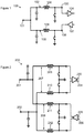
- the known switch arrangement 200 of figure 2 is substantially similar to figure 1 except that figure 2 shows a known differential quarter wavelength SPDT switch arrangement 200.
- the transceiver node comprises positive and negative transceiver nodes 201, 202 and the transmit node comprises positive and negative transmit nodes 203, 204 and the receive node comprises positive and negative receive nodes, 205, 206.
- the transmit path 207 further comprises a pair of transmit paths and the receive path 208 comprises a pair of receive paths.
- the pair of transmit paths each include an inductor.
- the pair of receive paths each include an inductor 209-212.
- the known differential quarter wavelength SPDT switch arrangement 200 includes at least four inductors.
- Such switch arrangements may be embodied as integrated circuits.
- the inductors 108, 109, 209, 210, 211, 212 may be area intensive on an integrated circuit's die.
- FIG. 3 shows an example embodiment comprising a switch arrangement 300.
- the switch arrangement 300 may comprise a switch arrangement of quarter wavelength SPDT type.
- the switch arrangement 300 comprises a transceiver node 301 via which signalling for transmission and received signalling is passed.
- the arrangement 300 comprises a first branch, which in this example is a transmit branch 302, which couples the transceiver node 301 to a transmit node 303.
- the transmit node 303 typically couples to an amplifier 304, such as directly or via other components, for onward transmission of the signalling passed through the transmit branch 302.
- the arrangement 300 further comprises a second branch, which in this example is a receive branch 305, separate from the transmit branch and in parallel therewith.
- the receive branch 305 couples the transceiver node 301 to a receive node 306.
- the receive node 306 typically couples to an amplifier 307 for amplification of received signalling received by the amplifier 307 for passing, such as directly or via other components, through the receive node 306 and the receive branch 305 to the transceiver node 301.
- the transmit branch 302 and the receive branch 305 extend from the transceiver node 301, such as directly from the transceiver node 301.
- the first branch may comprise the receive branch and the second branch may comprise the transmit branch and thus the branches may couple to the other of the transmit node and receive node.
- the switch arrangement 300 may be integrated in an integrated circuit.
- the transceiver node 301 and the transmit node 303 and the receive node 306 may represent the connections to/from the integrated circuit.
- the amplifiers 304, 307 in one or more examples, may be external to the integrated circuit and therefore the switch arrangement 300.
- the amplifiers 304, 307 or amplifier arrangements may be part of the switch arrangement 300 and may or may not be part of the integrated circuit.
- the switch arrangement 300 provides for selection of the transmit branch 302 or the receive branch such that the transceiver node 301 may receive signalling from outside the switch arrangement 300 for transmission via the transmit branch 302 and the transmit node 303 and, at a different time, such that the transceiver node 301 may receive received signalling from the receive node 306 via the receive branch 305.
- the switch arrangement 300 may provide for said selection based on the switch arrangement 100 being in a first switch mode or a second switch mode.
- the first or transmit circuit branch 302 comprises an inductor 310 coupled in series between the transceiver node 301 and the transmit node 303.
- the inductor 310 may be coupled directly to the transceiver node in the transmit branch, i.e. with no intervening electrical components, or with one or more electrical components therebetween.
- the first or transmit branch 302 includes a first semiconductor switch 311 coupled to the transmit node 303 and in parallel therewith. Thus, a first terminal 312 of the first semiconductor switch 311 may be coupled to a node 313 between the inductor 310 and the transmit node 303 and a second terminal 314 of the first semiconductor switch 311 may be coupled to none, one or more further components.
- nodes 313 and 303 are shown separately in the diagram it will be appreciated that in practice they could be the same node.
- said second terminal 314 is for coupling or is coupled to a reference voltage, such as ground 315.
- the second terminal 314 may be coupled to a node that is for coupling to a reference voltage when the switch arrangement is in use.
- the first semiconductor switch 311 may be coupled directly to the inductor 310, such as without a capacitor and/or further inductor therebetween.
- the first semiconductor switch 311 may be coupled directly to the transmit node 303, such as without a capacitor and/or further inductor and/or other component therebetween.
- the first semiconductor switch 311 may therefore provide a switched connection to the reference voltage 315.
- the first semiconductor switch 311 may be considered a first shunt switch.
- the state of the first semiconductor switch 311, i.e. open or closed, may be controlled by a control signal applied at a control terminal of the first semiconductor switch 311.
- the second or receive circuit branch 305 comprises a second semiconductor switch 316 coupled in series between the transceiver node 301 and the receive node 306.
- the second semiconductor switch 316 may be coupled directly to the transceiver node 301 i.e. with no intervening electrical components in the receive branch, or with one or more electrical components therebetween.
- the second or receive circuit branch 305 comprises a third semiconductor switch 317 (e.g. a second shunt switch) coupled to the receive node 306 and in parallel therewith.
- a first terminal 318 of the third semiconductor switch 317 may be coupled to a node 319 between the second semiconductor switch 316 and the receive node 306 and a second terminal 320 of the third semiconductor switch 317 may be coupled to none, one or more further components.
- said second terminal 320 is for coupling or is coupled to a reference voltage, such as ground 315.
- the second terminal 320 may be coupled to a node that is for coupling to a reference voltage when the switch arrangement is in use.
- the third semiconductor switch 317 may be coupled directly to the inductor 310, such as without a capacitor and/or further inductor therebetween.
- the third semiconductor switch 317 may be coupled directly to the transmit node 303, such as without a capacitor and/or further inductor and/or other component therebetween.
- the state of the second semiconductor switch 316 or the third semiconductor switch i.e. open or closed, may be controlled by a control signal applied at a control terminal of the second or third semiconductor switch 316, 317.
- the operation of the first, second and third semiconductor switches 311, 316 and 317 may provide for selection of one of the receive path 302 and the transmit path 305 in terms of preferential impedance matching between the transceiver node 301 and the respective transmit or receive node 303, 306.
- the switch arrangement 300 may substantially provide an impedance matched path between the transceiver node 301 and the transmit node 303 but not between the transceiver node 301 and the receive node 306, such that the switch arrangement provides a signal path between the transceiver node 301 and the transmit node 303.
- the switch arrangement 300 may substantially provide an impedance matched path between the transceiver node 301 and the receive node 306 but not between the transceiver node 301 and the transmit node 301, such that the switch arrangement provides a signal path between the transceiver node 301 and the receive node 306.
- the first semiconductor switch 311 and the second semiconductor switch 316 are open.
- the semiconductor switches are semiconductor based, and may comprise one of a transistor arrangement or biased diode arrangement, they have an intrinsic capacitance in the open state, sometimes termed the parasitic capacitance.
- the first semiconductor switch 311 and the second semiconductor switch 316, in the first switch mode, thereby provide a capacitance in the switch arrangement 300.
- the third semiconductor switch 317 in the first switch mode, is closed and therefore configured to provide a connection from the receive branch 305 to the reference voltage 315, such as ground.
- Example figure 4 shows the state of the first, second and third semiconductor switches 311, 316 and 317 in the first switch mode.
- the semiconductor switches In the open state, the semiconductor switches may be considered to present a capacitance to the switch arrangement. In the closed state, the semiconductor switches may be considered to present a resistance to the switch arrangement.
- the state of the semiconductor switches in the first switch mode, are configured to present a CLC network between the transceiver node 301 and the transmit node 303.
- the CLC network provides for the impedance matching between the transceiver node 301 and the one of the transmit node 303 and receive node 306 (in this embodiment the transmit node).
- the other of the transmit node 303 and the receive node 306 (in this embodiment the receive node) is shorted to the reference voltage by the closed third semiconductor switch 317. Accordingly, the impedance at the transceiver node 301 is not matched (i.e. mismatched) to the impedance at the receive node 306.
- Example figure 5 shows the first, second and third semiconductor switches 311, 316, 317 in the first switch mode replaced with the capacitor and resistor symbols to show an equivalent model of the switches in the first switch mode of the switch arrangement 300.
- the CLC network is provided by the capacitance 311 coupled to the reference voltage, the inductor 310 and the capacitance 317 connected to the reference voltage.
- the first semiconductor switch 311 and the second semiconductor switch 316 are closed. As the first semiconductor switch 311 is closed it is therefore configured to provide a connection from the transmit branch 302 to the reference voltage 315. In the closed state, the first semiconductor switch 311 may be considered to present a resistance in the switch arrangement. In one or more examples, in the second switch mode, the second semiconductor switch 316 is closed. The second semiconductor switch 316 therefore provides a direct coupling between the transceiver node 301 and the receive node 306.
- the third semiconductor switch in the second switch mode, is configured to be open and therefore presents a capacitance in parallel with the receive node 306.
- the state of the switches 311, 316, 317 provide for a parallel LC tank circuit that provides for the impedance matching between the transceiver node 301 and the other of the transmit node 303 and receive node 306 (in this embodiment the receive node).
- the arrangement is configured such that the inductor 310 tunes out the capacitance of the open first switch 317 to provide said impedance matching.
- the one of the transmit node 303 and the receive node 306 (in this embodiment the transmit node) is shorted to the reference voltage by the closed first semiconductor switch 311. Accordingly, the impedance at the transceiver node 301 is not matched (i.e. mismatched) to the impedance at the transmit node 303.
- Example figure 7 shows the first, second and third semiconductor switches 311, 316, 317 in the second switch mode replaced with the capacitor and resistor symbols to show an equivalent model of the switches in the switch arrangement 300.
- the state of the semiconductor switches are configured to present a parallel LC tank network between the transceiver node 301 and the receive node 306.
- the second or receive circuit branch is absent of an inductor.
- the second circuit branch 305 is absent of an inductor between the transceiver node 301 and the receive node 306.
- the switch arrangement of example figures 3 to 7 may be considered area efficient and may be of lesser size than that of figure 1 .
- the inductor 310 may have inductance L and, in the first switch mode, the first semiconductor switch 311 may have a capacitance C off1 , the second semiconductor switch 316 may have a capacitance C off2 and the third semiconductor switch may have a resistance R on3 .
- the interface impedance of the transceiver node is Z 0 (Z 0 is usually 50 ⁇ ).
- the first, second and third semiconductor switches therefore provide a CLC network comprising, respectively, the shunt capacitance Coff1, the series inductance L, and the shunt capacitance Coff2.
- the CLC network, in the first switch mode should transform impedance from Z 0 to Z 0 .
- the inductor 310 still has an inductance L and, in the second switch mode, the first semiconductor switch 311 may have a resistance R on1 , the second semiconductor switch 316 may have a resistance R on2 and the third semiconductor switch may have a capacitance C off3 .
- the interface impedance of the transceiver node is Z 0 (Z 0 is usually 50 ⁇ ).
- the first, second and third semiconductor switches therefore provide a parallel LC tank network with the inductor 310 comprising the shunt inductance L and the shunt capacitance C off3 .
- the LC network, formed in the second switch mode, should transform impedance from Z 0 to Z 0 .
- L and C off3 may be configured to resonate at the operational frequency.
- the value of the inductor 310 may be determined using the above equation 2 and then the value of the capacitances may be determined using equation 1. It will be appreciated that these equations represent a simplified case and therefore the inductances and capacitances may be determined differently.
- the semiconductor switches 311, 316, 317 are configured present a resistance in the on/closed state and a capacitance in the off/open state. It will also be appreciated that there are many possible arrangements of semiconductor switch that exhibit these properties. Example figures 8 to 11 show four of many possible configurations for such a semiconductor switch.
- the first switch mode may comprise a receive mode or a transmit mode and the second switch mode may comprise the other of a receive mode or a transmit mode depending on the configuration of the first and second branches as transmit or receive branches.
- Example figure 8 shows a semiconductor switch 311 and 317 comprising a MOS transistor, such as an n-channel MOSFET 800.
- the MOSFET 800 comprises a drain terminal 801 coupled to a first capacitor 802 and a source terminal 803 coupled to a second capacitor 804.
- the drain terminal 801 is coupled to the respective transmit node 303 and the receive node 306 via the first capacitor 802.
- the source terminal 803 is coupled to or for coupling to the reference voltage, such as ground 315, via the second capacitor 804.
- the state of the semiconductor switch i.e.
- control signal comprising a first, second and third control signal respectively applied at each of the drain terminal 801, a gate terminal 805 of the MOSFET and the source terminal 803 (in this example each via a resistor).
- the semiconductor switch is open/off when the first and third control signals are low and the second control signal is high.
- the semiconductor switch is closed/on when the first and third control signals are high and the second control signal is low.
- Example figure 9 shows a bipolar junction transistor (BJT) 900 of npn type.
- BJT bipolar junction transistor
- a collector terminal 901 is coupled to the respective transmit node 303 and the receive node 306.
- An emitter terminal 902 is for coupling to a reference voltage, such as ground.
- the state of the semiconductor switch i.e. open or closed, is, in this example, controlled by a control signal applied at the base terminal 903 via a resistor. Application of a voltage at the base terminal provides the closed or on state for the switch.
- Example figure 10 shows a forward saturation mode npn BJT transistor 1000.
- an emitter terminal 1001 coupled to the respective transmit node and the receive node and a collector terminal 1002 for coupling to the reference voltage 315.
- the state of the semiconductor switch i.e. open or closed, is, in this example, controlled by a control signal applied at the base terminal 1003 via a resistor. Application of a voltage at the base terminal provides the closed or on state for the switch.
- Example figure 11 shows a pin diode 1100.
- a cathode 1101 thereof is coupled to the respective transmit node and the receive node and an anode 1102 thereof is for coupling to the reference voltage 315 via a capacitor 1103.
- the state of the semiconductor switch i.e. open or closed, is, in this example, controlled by a control signal applied at the anode 1102 via a resistor 1104.
- Application of a voltage at the anode 1102 biases the diode and provides the closed or on state for the switch.
- Example figures 21 to 24 show embodiments of the series arranged second semiconductor switch 316.
- the examples of Figures 21 to 23 have a similar configuration.
- the example of figure 21 comprises a MOS transistor 2100, such as an n-channel MOSFET.
- the MOSFET 2100 comprises a drain terminal 2101 coupled to a first capacitor 2102 and a source terminal 2103 coupled to a second capacitor 2104.
- the drain terminal 2101 is coupled to the transceiver node 301 via the first capacitor 2102.
- the source terminal 2103 is coupled to the other of the transmit node and receive node, which in this example comprises the receive node, via the second capacitor 2104.
- the state of the semiconductor switch i.e.
- control signal comprising a first, second and third control signal respectively applied at each of the drain terminal 2101, a gate terminal 2105 of the MOSFET and the source terminal 2103 (in this example each via a resistor).
- the semiconductor switch is open/off when the first and third control signals are low and the second control signal is high.
- the semiconductor switch is closed/on when the first and third control signals are high and the second control signal is low.
- Example figures 22 and 23 show a similar arrangement using a BJT 2200, 2300 rather than the MOSFET 2100.
- Example figures 22, 23 show a bipolar junction transistor (BJT) 2200, 2300 of npn type.
- a collector terminal 2201, 2303 is coupled to either the transceiver node 301 or the one of the transmit node and receive node via capacitor 2304, 2202.
- An emitter terminal 2203, 2301 is coupled to the other of either the transceiver node 301 and the one of the transmit node and receive node via a capacitor 2302, 2204.
- the state of the semiconductor switch 2205, 2305 i.e.
- open or closed is, in this example, controlled by a first control signal applied at the base terminal 2205, 2305 via a resistor as well as separate second and third control signals at the collector and emitter terminals, applied via resistors.
- Application of a high voltage at the base terminal provides the closed or on state for the switch while the second and third control signals are low.
- a low first control signal with high second and third control signals provides the open or off state.
- Example figure 24 shows a diode 2400.
- a cathode 2401 thereof is coupled to the respective transmit node and the receive node and an anode 1102 thereof is coupled to the transceiver node 301, both via a capacitor 2403, 2404.
- the state of the semiconductor switch i.e. open or closed, is, in this example, controlled by a first control signal applied at the anode via a resistor and a second control signal applied at the cathode via a resistor.
- a high voltage at the anode and a low voltage at the cathode biases the diode and provides the closed or on state for the switch.
- a low voltage at the anode and a high voltage at the cathode provides the open or off state for the switch.
- Example figure 12 shows the same switch arrangement as example figure 3 expect that the amplifier 307 is shown in more detail.
- the amplifier 307 comprises a receive path buffer amplifier.
- the amplifier 307 comprises a transistor, such as a bipolar junction transistor (BJT) 1200 of npn type.
- the amplifier/transistor is coupled with further ancillary components.
- a collector terminal 1201 is coupled to the receive node 306, such as via a DC blocking capacitor 1202.
- the capacitor 1202 may be ignored when considering the coupling of an RF signal between the transceiver node and the transistor 1200.
- the collector terminal 1201 is further coupled, in parallel, with a power supply node 1203 via an inductor 1204.
- the power supply node 1203 is for connection to a power supply.
- An emitter terminal 1205 is for coupling to the reference voltage, such as ground 315. The remainder of the receive path may connect to the base terminal.
- Example figure 13 shows a further example of the switch arrangement 1300.
- the third semiconductor switch 317 is provided by a semiconductor switch 1317 configured to provide a switched connection between the power supply node 1203 and the transistor 1200.
- a first terminal of the switch 1317 is coupled to the power supply node 1203 and a second terminal of the switch 1317 is coupled to the transistor 1200 via the inductor 1204.
- a first plate of a decoupling capacitor 1301 may be coupled in parallel to a node between the second terminal of the switch 1317 and the inductor 1204.
- a second plate of the decoupling capacitor 1301 may be for coupling to a reference voltage, such as ground 315.
- the third semiconductor switch as the power supply switch 1317, insertion losses may be reduced. Further, in one or more examples, the third switch 317 may limit the receive path output voltage swing headroom. Thus, by providing the third switch as power supply switch 1317, this may increase the limit of the output power from the receive path.
- the transistor 1200 may comprise a transistor of any one of the following types: npn common-emitter; a common-base or cascode stage; a nmos common-source; a common-gate or cascode stage; a pnp emitter follower; and a pmos source follower.
- Example figures 14 and 15 show the status of the first, second and third semiconductor switches 311, 316 and 1317 in the first and second switch modes respectively.
- the first semiconductor switch 311 and the second semiconductor switch 316 are open.
- the third semiconductor switch 1317 is open and, accordingly, the power supply node 1203 is disconnected or decoupled from the amplifier or transistor 1200. Accordingly, the transistor 1200 is pushed into forward saturation mode to make a short termination to the reference voltage, ground 315.
- the impedance at node 1400 and therefore the receive node 306 is approximately 0 Ohms.
- the receive node is shorted to ground and there is no impedance matching between the transceiver node 301 and the receive node 306/node 1400. The principle is then the same as described in relation to figure 4 and figure 5 .
- a CLC network is formed of the capacitance of the open first semiconductor switch 311 plus the inductor 310 plus the capacitance of the open second semiconductor switch 316, which is also coupled to the reference voltage through transistor 1200 (C off1 + series L + C off2 ).
- the CLC network or, more generally the switch arrangement 1300 transforms impedance Z 0 at the transceiver node to Z 0 at the transmit node 303.
- the signalling will thereby flow from the transceiver node 301 to the transmit node 303 (the impedance matched path) rather than from the receive node 306 to the transceiver node 301 (the non-impedance matched path).
- the first semiconductor switch 311 and the second semiconductor switch 316 are closed.
- the third semiconductor switch 1317 is closed and, accordingly, the power supply node is coupled to the amplifier or transistor 1200. Accordingly, the transistor 1200 is active.
- the transmit node 303 is shorted to the reference voltage by the closed first semiconductor switch 311 and therefore is not impedance matched with the transceiver node 301.
- the inductor 310 and the inductor 1204 form part of a receive path output matching network.
- a parallel LC tank network is formed but with the two inductors 310 and 1204 rather than the single inductor of the previous example.
- the parallel LC tank network acts to tune out the output capacitance that is inherent in the buffer transistor 1200 to provide impedance matching between the transceiver node 301 and the receive node 306 and thus the amplifier 1200.
- the signalling will thereby flow from the receive node 306 to the transceiver node 301 (the impedance matched path) rather than from the transceiver node 301 to the transmit node 303 (the non-impedance matched path).
- the switch arrangement 1300 comprises a third semiconductor switch 1317 that comprises part of an amplifier arrangement coupled with the receive node 306 of the receive path 305.
- the third semiconductor switch 1317 is configured to control the application of a supply voltage to an amplifier 1200, wherein in the first switch mode the third switch is open and a connection between the receive path 305 and a reference voltage, such as ground 315, is provided through the amplifier 1200. In the second switch mode, the third semiconductor switch 1317 is closed and the amplifier is provided with the supply voltage. Accordingly, the inductor 1204 and inductor 310 act to provide impedance matching between the transceiver node 301 and the amplifier 1200 of the receive path 305.
- Example figure 16 shows a further example of a switch arrangement 1600, which is similar to the switch arrangement 1300 of figure 13 .
- the second switch 316 is absent and a further semiconductor switch 1617 provides the function of the second and third semiconductor switches 316, 1317 in the previous examples. The differences over the switch arrangement 1300 will now be described.
- the example switch arrangement 1600 includes an amplifier arrangement comprising a series arrangement of a supply node 1203 for receiving a supply voltage, a further inductor 1604, a npn transistor 1200 comprising a collector terminal 1201 coupled with the inductor 1204 and an emitter terminal 1205 for connection to the reference voltage 315.
- the receive node 306 in this example is coupled to a node 1601 between the inductor 1604 and the collector terminal 1201 via a DC blocking capacitor 1202. Accordingly, when considering the flow of RF signalling the DC blocking capacitor 1202 may be ignored.
- the amplifier arrangement 1600 in this example, further comprises a bias circuit 1602 coupled to a base terminal 1603 of the transistor 1200 and configured to apply a bias voltage to the base terminal 1603.
- the application of the bias voltage is controlled by the further semiconductor switch 1617.
- the amplifier comprises a npn transistor, although could be embodied as a transistor of any one of the following types: npn common-emitter; a common-base or cascode stage; a nmos common-source; a common-gate or cascode stage; a pnp emitter follower; and a pmos source follower.
- the further semiconductor switch 1617 in the first switch mode, is open and the bias voltage is not applied to the base terminal 1603.
- the first semiconductor switch 311 is also open and thus provides a capacitance.
- the box 1722 is shown to demonstrate that the transistor 1200 has an intrinsic capacitance 1721 and an intrinsic resistance 1720.
- components 1720 and 1721 are not distinct components but representations of the electrical properties of the transistor 1200.
- the same box 1722 is shown in example figure 18 .
- the further semiconductor switch 1617 in the second switch mode, is closed and the bias voltage is applied to the base terminal 1603.
- the first semiconductor switch 311 is closed and thus connects the transmit node 303 of the first branch 302 to the reference voltage 315.
- example figures 17 and 18 show an intrinsic resistance of the transistor 1200 as resistor 1720 with given resistance value R out .
- Example figures 17 and 18 also show an intrinsic capacitance of the transistor 1200 as capacitor 1721 with given capacitance C out .
- the inductance of the inductor 1204 is L 2 .
- the switch arrangement 1600 can be simplified to a CLC network 1750 wherein the capacitance is provided by the open first semiconductor switch 311, the inductance by the inductor 310 and the other capacitance by the intrinsic capacitance 1721 of the transistor 1200.
- impedance matching is provided between the transceiver node 310 and the transmit node 303 or, more generally, the one of the transmit node and receive node of the first branch.
- R out is dependent on the current through the transistor 1200 and in the second switch mode the resistance 1720 or R out is low, such as around 100 Ohms.
- the switch arrangement in the second switch mode provides for shorting of the transmit node 303 (i.e. one of the transmit and receive nodes) to the reference voltage by the first semiconductor switch 311. Further, the switch arrangement 1600 in the second switch mode provides a parallel LC tank circuit formed, in this example, of both inductors 310 and 1604 in parallel and the intrinsic junction capacitance of the transistor 1200 shown as 1721.
- Cout is the mainly from the junction capacitance of npn transistor, so it is not particularly tunable.
- the inductors 310, 1604, namely L1 and L2 are configured to tune out Cout in the second switch mode to provide the impendence matching between the transceiver node 301 and the receive node 306/transistor 1200.
- L1 Zo ⁇
- L2 Since L1 is determined and Cout is known, L2 can be calculated accordingly.
- Example figures 19 and 20 comprise examples of a switch arrangement 1900, 2000 of differential type with a reduced number of inductors, consistent with the switch arrangement 300 of example figure 3 .
- the layout of the arrangements 1900, 2000 is broadly in line with the example arrangement 300 of Figure 3 .
- the arrangement 1900 comprises a transceiver node which in this differential example comprises a positive transceiver node 1901 and a negative transceiver node 1902.
- the transmit node comprises a positive transmit node 1903 and a negative transmit node 2003.
- the receive node comprises a positive receive node 1906 and a negative receive node 2006.
- the first circuit branch comprises a first positive circuit branch 1902 and a first negative circuit branch 2002 coupled to the respective positive and negative transmit nodes 1903, 2003.
- the inductor comprises a first inductor 1910 in the first positive circuit branch 1902 and a second inductor 2010 in the first negative circuit branch 2002, the first inductor 1910 is coupled in series between the positive transceiver node 1901 and the positive transmit node 1903 and the second inductor 2010 is coupled in series between the negative transceiver node 2001 and the negative transmit node 2003.
- the first semiconductor switch 1911 is in parallel with both the positive transmit node 1903 and the negative transmit node 2003. Further, in one or more examples, the first semiconductor switch 1911 comprises a pair of first semiconductor switches each for selectively coupling one of the first positive circuit branch 1902 and the first negative circuit branch 2002 to a reference voltage, such as ground 315.
- the second circuit branch comprises a second positive circuit branch 1905 and a second negative circuit branch 2005 coupled to the respective positive and negative receive nodes 1906, and 2006.
- the second semiconductor switch 1916 comprises a pair of switches comprising a second-positive semiconductor switch 1916 and a second-negative semiconductor switch 2016, the second positive circuit branch 1905 includes the second-positive semiconductor switch 1916 coupled in series between the positive transceiver node 1901 and the positive receive node 1906 and the second negative circuit branch 2005 includes the second-negative semiconductor switch 2016 coupled in series between the negative transceiver node 2001 and the negative receive node 2006.
- the third semiconductor switch 1917 is in parallel with both the positive receive node 1906 and the negative receive node 2006. Further, in this and one or more examples, the third semiconductor switch 1917 comprises a pair of third semiconductor switches each for selectively coupling one of the second positive circuit branch 1905 and the second negative circuit branch 2005 to a reference voltage, such as ground 315.
- first positive circuit branch 1902 and a first negative circuit branch 2002 comprise a transmit branch and the second positive circuit branch 1905 and the second negative circuit branch 2005 comprise a receive branch.
- branch designated "first” may comprise the receive branch and the branch designated "second" may comprise the transmit branch.
- the first semiconductor switch 1911 comprises a pair of first semiconductor switches, wherein a first of the pair is configured to provide a switched connection to a reference voltage for the first positive circuit branch 1902 and a second of the pair is configured to provide a switched connection to the reference voltage for the first negative circuit branch 2002.
- Figure 20 shows an example switch arrangement 2000.
- the example switch arrangement 2000 of figure 20 is substantially the same as that of figure 19 and the same reference numerals have been used for like parts.
- the first semiconductor switch 2011 is configured to provide a switched connection between the first positive circuit branch 1902 and the first negative circuit branch 2002.
- the third semiconductor switch 2017 is configured to provide a switched connection between the second positive circuit branch 1905 and the second negative circuit branch 2005.
- the operation of the switch arrangement 1900, 2000 in terms of the first and second switching modes is similar to the example described in relation to figures 4 to 7 .
- the first semiconductor switch 1911, 2011 or pair of first semiconductor switches 1911 are open and therefore provide a capacitance, similar to example Figure 5 .
- the second semiconductor switches 1916, 2016 are open and therefore provide a capacitance, similar to example Figure 5 .
- the third semiconductor switch 1917, 2017 or pair of third semiconductor switches 1917 are closed and therefore provide a coupling to ground 315 or short the second positive and second negative branches 1902, 2002.
- the first semiconductor switch 1911, 2011 or pair of first semiconductor switches 1911 are closed and provide a coupling to ground 315 or short the first positive and first negative branches 1902, 2002.
- the second semiconductor switches 1916, 2016 are closed.
- the third semiconductor switch 1917, 2017 or pair of third semiconductor switches 1917 are open and therefore provide a capacitance between the corresponding branch and ground 315 or between the second positive and second negative branches 1905, 2005.
- the switch arrangement 1900, 2000 provides for substantially matching of the impendence between the positive transceiver node 1901 and the positive transmit node 1903 and for substantially matching of the impendence between the negative transceiver node 2001 and the negative transmit node 2003.
- the impedance between the positive transceiver node 1901 and the positive receive node 1906 and the impendence between the negative transceiver node 2001 and the negative receive node 2006 is substantially unmatched.
- the switch arrangement 1900, 2000 provides for substantially matching of the impendence between the positive transceiver node 1901 and the positive receive node 1906 and for substantially matching of the impendence between the negative transceiver node 2001 and the negative receive node 2006.
- the impedance between the positive transceiver node 1901 and the positive transmit node 1903 and the impendence between the negative transceiver node 2001 and the negative transmit node 2003 is substantially unmatched.
- Example figure 25 shows a method of operating a switch arrangement 300, 1300,1600, 1900, 2000, wherein, the method comprises switching between:
- the example method comprises switching back to the first switch mode at 2503.
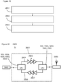
- Figure 26 shows a communication device 2600 comprising an RF front-end integrated circuit 2601, a transceiver 2602, and an antenna. It will be appreciated that the communication device may include further components connected to the transceiver 2602.
- the front-end integrated circuit comprises two instances of the switch arrangement 300, 1300, 1600, 1700 to control the flow of signalling between the transceiver 2602 and the antenna 2603 over either a transmit path 2604 comprising one or more amplifiers 2605 and a receive path 2606 comprising one or more amplifiers 2607.
- the device 2600 includes one or more antennas 2603 coupled to the transmit node and receive node via one or more amplifiers and one or more signal processing elements, such as transceiver 2602, for providing communication functionality, coupled to the transceiver node, the switch modes operable to provide for half-duplex transmission and reception of signalling by the telecommunication device 2600.
- the signal processing element 2202 may provide for processing of signalling for transmission and signalling that is received.
- the set of instructions/method steps described above are implemented as functional and software instructions embodied as a set of executable instructions which are effected on a computer or machine which is programmed with and controlled by said executable instructions. Such instructions are loaded for execution on a processor (such as one or more CPUs).
- processor includes microprocessors, microcontrollers, processor modules or subsystems (including one or more microprocessors or microcontrollers), or other control or computing devices.
- a processor can refer to a single component or to plural components.
- the set of instructions/methods illustrated herein and data and instructions associated therewith are stored in respective storage devices, which are implemented as one or more non-transient machine or computer-readable or computer-usable storage media or mediums.
- Such computer-readable or computer usable storage medium or media is (are) considered to be part of an article (or article of manufacture).
- An article or article of manufacture can refer to any manufactured single component or multiple components.
- the non-transient machine or computer usable media or mediums as defined herein excludes signals, but such media or mediums may be capable of receiving and processing information from signals and/or other transient mediums.
- Example embodiments of the material discussed in this specification can be implemented in whole or in part through network, computer, or data based devices and/or services. These may include cloud, internet, intranet, mobile, desktop, processor, look-up table, microcontroller, consumer equipment, infrastructure, or other enabling devices and services. As may be used herein and in the claims, the following non-exclusive definitions are provided.
- one or more instructions or steps discussed herein are automated.
- the terms automated or automatically mean controlled operation of an apparatus, system, and/or process using computers and/or mechanical/electrical devices without the necessity of human intervention, observation, effort and/or decision.
- any components said to be coupled may be coupled or connected either directly or indirectly.
- additional components may be located between the two components that are said to be coupled.
Priority Applications (3)
| Application Number | Priority Date | Filing Date | Title |
|---|---|---|---|
| EP19159726.9A EP3703267A1 (fr) | 2019-02-27 | 2019-02-27 | Agencement de commutateur |
| CN202010097831.0A CN111628759A (zh) | 2019-02-27 | 2020-02-17 | 开关布置 |
| US16/794,846 US10985795B2 (en) | 2019-02-27 | 2020-02-19 | Switch arrangement |
Applications Claiming Priority (1)
| Application Number | Priority Date | Filing Date | Title |
|---|---|---|---|
| EP19159726.9A EP3703267A1 (fr) | 2019-02-27 | 2019-02-27 | Agencement de commutateur |
Publications (1)
| Publication Number | Publication Date |
|---|---|
| EP3703267A1 true EP3703267A1 (fr) | 2020-09-02 |
Family
ID=65635451
Family Applications (1)
| Application Number | Title | Priority Date | Filing Date |
|---|---|---|---|
| EP19159726.9A Withdrawn EP3703267A1 (fr) | 2019-02-27 | 2019-02-27 | Agencement de commutateur |
Country Status (3)
| Country | Link |
|---|---|
| US (1) | US10985795B2 (fr) |
| EP (1) | EP3703267A1 (fr) |
| CN (1) | CN111628759A (fr) |
Families Citing this family (3)
| Publication number | Priority date | Publication date | Assignee | Title |
|---|---|---|---|---|
| EP3934095A1 (fr) * | 2020-07-03 | 2022-01-05 | Nxp B.V. | Combineur de puissance de wilkinson, unité de communication et procédé associé |
| US11695193B2 (en) | 2020-12-14 | 2023-07-04 | Nxp B.V. | Wilkinson power combiner, communication unit and method therefor |
| US11546011B1 (en) * | 2021-09-15 | 2023-01-03 | Harris Global Communications, Inc. | RF device with biasing circuit for PIN diode and related methods |
Citations (4)
| Publication number | Priority date | Publication date | Assignee | Title |
|---|---|---|---|---|
| EP0446050A2 (fr) * | 1990-03-08 | 1991-09-11 | Sony Corporation | Dispositif de commutation de signaux d'émission/réception |
| US20020006810A1 (en) * | 2000-06-30 | 2002-01-17 | Heiko Schiller | Antenna changeover switch for transmit-receive units in a mobile station |
| US20110285475A1 (en) * | 2010-05-21 | 2011-11-24 | Yuan Lu | RF Front-End with Integrated T/R Switch |
| US20140065984A1 (en) * | 2012-08-31 | 2014-03-06 | Toshiba Kaisha Toshiba | Transmit-receive switching circuit and wireless device |
Family Cites Families (2)
| Publication number | Priority date | Publication date | Assignee | Title |
|---|---|---|---|---|
| TWI500278B (zh) * | 2012-08-15 | 2015-09-11 | Realtek Semiconductor Corp | 訊號轉換電路與訊號轉換方法 |
| US9042844B2 (en) * | 2013-01-16 | 2015-05-26 | Mediatek Singapore Pte. Ltd. | Transceiver and related switching method applied therein |
-
2019
- 2019-02-27 EP EP19159726.9A patent/EP3703267A1/fr not_active Withdrawn
-
2020
- 2020-02-17 CN CN202010097831.0A patent/CN111628759A/zh active Pending
- 2020-02-19 US US16/794,846 patent/US10985795B2/en active Active
Patent Citations (4)
| Publication number | Priority date | Publication date | Assignee | Title |
|---|---|---|---|---|
| EP0446050A2 (fr) * | 1990-03-08 | 1991-09-11 | Sony Corporation | Dispositif de commutation de signaux d'émission/réception |
| US20020006810A1 (en) * | 2000-06-30 | 2002-01-17 | Heiko Schiller | Antenna changeover switch for transmit-receive units in a mobile station |
| US20110285475A1 (en) * | 2010-05-21 | 2011-11-24 | Yuan Lu | RF Front-End with Integrated T/R Switch |
| US20140065984A1 (en) * | 2012-08-31 | 2014-03-06 | Toshiba Kaisha Toshiba | Transmit-receive switching circuit and wireless device |
Also Published As
| Publication number | Publication date |
|---|---|
| CN111628759A (zh) | 2020-09-04 |
| US10985795B2 (en) | 2021-04-20 |
| US20200274575A1 (en) | 2020-08-27 |
Similar Documents
| Publication | Publication Date | Title |
|---|---|---|
| EP3547536B1 (fr) | Système et procédé permettant de contourner un amplificateur à faible bruit | |
| US10985795B2 (en) | Switch arrangement | |
| US6636119B2 (en) | Compact cascode radio frequency CMOS power amplifier | |
| CN106026952B (zh) | 用于针对毫米波功率应用的共源共栅放大器拓扑结构的设备和方法 | |
| US7619482B1 (en) | Compact low voltage low noise amplifier | |
| US9768736B2 (en) | Power amplifier cell | |
| US8508302B2 (en) | Electronic circuit | |
| US8390395B2 (en) | High power RF switch with active device size tapering | |
| CN103051297A (zh) | 电路和功率放大器 | |
| US20140333385A1 (en) | Dual-band semiconductor rf amplifier device | |
| CN105680803A (zh) | 用于低噪声放大器模块的系统和方法 | |
| CN104660183B (zh) | 放大器电路 | |
| US7102444B2 (en) | Method and apparatus for compensating and improving efficiency in a variable power amplifier | |
| TWI389448B (zh) | 可變頻率響應之低雜訊放大器及切換頻率響應之方法 | |
| US11190138B2 (en) | Power amplifier circuit and power amplifier module | |
| US20070103235A1 (en) | Inductorless broadband RF low noise amplifier | |
| CN111756337A (zh) | 级联放大器偏置 | |
| US20080248776A1 (en) | High-frequency circuit | |
| EP3930203A1 (fr) | Dispositif de commutation, système et procédés correspondants | |
| US20070146078A1 (en) | Selective amplifier | |
| CN103166579B (zh) | 放大装置 | |
| US20050156670A1 (en) | Method and apparatus for optimization of amplifier with adjustable output range | |
| CN111162764A (zh) | 一种射频抗烧毁保护电路以及高功率射频开关 | |
| EP4187786A1 (fr) | Circuit d'atténuation | |
| US11309842B2 (en) | Power amplifier circuit |
Legal Events
| Date | Code | Title | Description |
|---|---|---|---|
| PUAI | Public reference made under article 153(3) epc to a published international application that has entered the european phase |
Free format text: ORIGINAL CODE: 0009012 |
|
| STAA | Information on the status of an ep patent application or granted ep patent |
Free format text: STATUS: THE APPLICATION HAS BEEN PUBLISHED |
|
| AK | Designated contracting states |
Kind code of ref document: A1 Designated state(s): AL AT BE BG CH CY CZ DE DK EE ES FI FR GB GR HR HU IE IS IT LI LT LU LV MC MK MT NL NO PL PT RO RS SE SI SK SM TR |
|
| AX | Request for extension of the european patent |
Extension state: BA ME |
|
| STAA | Information on the status of an ep patent application or granted ep patent |
Free format text: STATUS: REQUEST FOR EXAMINATION WAS MADE |
|
| 17P | Request for examination filed |
Effective date: 20210302 |
|
| RBV | Designated contracting states (corrected) |
Designated state(s): AL AT BE BG CH CY CZ DE DK EE ES FI FR GB GR HR HU IE IS IT LI LT LU LV MC MK MT NL NO PL PT RO RS SE SI SK SM TR |
|
| STAA | Information on the status of an ep patent application or granted ep patent |
Free format text: STATUS: EXAMINATION IS IN PROGRESS |
|
| 17Q | First examination report despatched |
Effective date: 20220201 |
|
| STAA | Information on the status of an ep patent application or granted ep patent |
Free format text: STATUS: THE APPLICATION IS DEEMED TO BE WITHDRAWN |
|
| 18D | Application deemed to be withdrawn |
Effective date: 20230817 |