EP3703229A1 - Rotary apparatus - Google Patents
Rotary apparatus Download PDFInfo
- Publication number
- EP3703229A1 EP3703229A1 EP18871323.4A EP18871323A EP3703229A1 EP 3703229 A1 EP3703229 A1 EP 3703229A1 EP 18871323 A EP18871323 A EP 18871323A EP 3703229 A1 EP3703229 A1 EP 3703229A1
- Authority
- EP
- European Patent Office
- Prior art keywords
- casing
- rotating shaft
- bearing
- rotating device
- motor
- Prior art date
- Legal status (The legal status is an assumption and is not a legal conclusion. Google has not performed a legal analysis and makes no representation as to the accuracy of the status listed.)
- Ceased
Links
- 239000000463 material Substances 0.000 claims description 11
- 239000011347 resin Substances 0.000 claims description 8
- 229920005989 resin Polymers 0.000 claims description 8
- 239000000203 mixture Substances 0.000 claims description 5
- 239000007769 metal material Substances 0.000 claims description 4
- 230000005540 biological transmission Effects 0.000 description 41
- 239000004020 conductor Substances 0.000 description 16
- 238000004378 air conditioning Methods 0.000 description 15
- 238000010586 diagram Methods 0.000 description 10
- 230000004048 modification Effects 0.000 description 8
- 238000012986 modification Methods 0.000 description 8
- 238000004519 manufacturing process Methods 0.000 description 5
- 239000012790 adhesive layer Substances 0.000 description 3
- 230000002159 abnormal effect Effects 0.000 description 2
- 230000009191 jumping Effects 0.000 description 2
- 239000002184 metal Substances 0.000 description 2
- 229910052751 metal Inorganic materials 0.000 description 2
- -1 polypropylene Polymers 0.000 description 2
- 238000005476 soldering Methods 0.000 description 2
- 239000004925 Acrylic resin Substances 0.000 description 1
- 229920000178 Acrylic resin Polymers 0.000 description 1
- RYGMFSIKBFXOCR-UHFFFAOYSA-N Copper Chemical compound [Cu] RYGMFSIKBFXOCR-UHFFFAOYSA-N 0.000 description 1
- 239000004642 Polyimide Substances 0.000 description 1
- 239000004743 Polypropylene Substances 0.000 description 1
- 229920000122 acrylonitrile butadiene styrene Polymers 0.000 description 1
- 239000004676 acrylonitrile butadiene styrene Substances 0.000 description 1
- 238000001816 cooling Methods 0.000 description 1
- 229910052802 copper Inorganic materials 0.000 description 1
- 239000010949 copper Substances 0.000 description 1
- 230000000694 effects Effects 0.000 description 1
- 238000005516 engineering process Methods 0.000 description 1
- 239000003822 epoxy resin Substances 0.000 description 1
- 239000003365 glass fiber Substances 0.000 description 1
- 238000000034 method Methods 0.000 description 1
- 229920000647 polyepoxide Polymers 0.000 description 1
- 229920000728 polyester Polymers 0.000 description 1
- 229920000139 polyethylene terephthalate Polymers 0.000 description 1
- 239000005020 polyethylene terephthalate Substances 0.000 description 1
- 229920001721 polyimide Polymers 0.000 description 1
- 229920001155 polypropylene Polymers 0.000 description 1
Images





Classifications
-
- H—ELECTRICITY
- H02—GENERATION; CONVERSION OR DISTRIBUTION OF ELECTRIC POWER
- H02K—DYNAMO-ELECTRIC MACHINES
- H02K7/00—Arrangements for handling mechanical energy structurally associated with dynamo-electric machines, e.g. structural association with mechanical driving motors or auxiliary dynamo-electric machines
- H02K7/08—Structural association with bearings
- H02K7/081—Structural association with bearings specially adapted for worm gear drives
-
- H—ELECTRICITY
- H02—GENERATION; CONVERSION OR DISTRIBUTION OF ELECTRIC POWER
- H02K—DYNAMO-ELECTRIC MACHINES
- H02K5/00—Casings; Enclosures; Supports
- H02K5/24—Casings; Enclosures; Supports specially adapted for suppression or reduction of noise or vibrations
-
- F—MECHANICAL ENGINEERING; LIGHTING; HEATING; WEAPONS; BLASTING
- F16—ENGINEERING ELEMENTS AND UNITS; GENERAL MEASURES FOR PRODUCING AND MAINTAINING EFFECTIVE FUNCTIONING OF MACHINES OR INSTALLATIONS; THERMAL INSULATION IN GENERAL
- F16C—SHAFTS; FLEXIBLE SHAFTS; ELEMENTS OR CRANKSHAFT MECHANISMS; ROTARY BODIES OTHER THAN GEARING ELEMENTS; BEARINGS
- F16C17/00—Sliding-contact bearings for exclusively rotary movement
- F16C17/04—Sliding-contact bearings for exclusively rotary movement for axial load only
- F16C17/08—Sliding-contact bearings for exclusively rotary movement for axial load only for supporting the end face of a shaft or other member, e.g. footstep bearings
-
- F—MECHANICAL ENGINEERING; LIGHTING; HEATING; WEAPONS; BLASTING
- F16—ENGINEERING ELEMENTS AND UNITS; GENERAL MEASURES FOR PRODUCING AND MAINTAINING EFFECTIVE FUNCTIONING OF MACHINES OR INSTALLATIONS; THERMAL INSULATION IN GENERAL
- F16C—SHAFTS; FLEXIBLE SHAFTS; ELEMENTS OR CRANKSHAFT MECHANISMS; ROTARY BODIES OTHER THAN GEARING ELEMENTS; BEARINGS
- F16C17/00—Sliding-contact bearings for exclusively rotary movement
- F16C17/10—Sliding-contact bearings for exclusively rotary movement for both radial and axial load
-
- F—MECHANICAL ENGINEERING; LIGHTING; HEATING; WEAPONS; BLASTING
- F16—ENGINEERING ELEMENTS AND UNITS; GENERAL MEASURES FOR PRODUCING AND MAINTAINING EFFECTIVE FUNCTIONING OF MACHINES OR INSTALLATIONS; THERMAL INSULATION IN GENERAL
- F16C—SHAFTS; FLEXIBLE SHAFTS; ELEMENTS OR CRANKSHAFT MECHANISMS; ROTARY BODIES OTHER THAN GEARING ELEMENTS; BEARINGS
- F16C17/00—Sliding-contact bearings for exclusively rotary movement
- F16C17/12—Sliding-contact bearings for exclusively rotary movement characterised by features not related to the direction of the load
- F16C17/24—Sliding-contact bearings for exclusively rotary movement characterised by features not related to the direction of the load with devices affected by abnormal or undesired positions, e.g. for preventing overheating, for safety
-
- F—MECHANICAL ENGINEERING; LIGHTING; HEATING; WEAPONS; BLASTING
- F16—ENGINEERING ELEMENTS AND UNITS; GENERAL MEASURES FOR PRODUCING AND MAINTAINING EFFECTIVE FUNCTIONING OF MACHINES OR INSTALLATIONS; THERMAL INSULATION IN GENERAL
- F16C—SHAFTS; FLEXIBLE SHAFTS; ELEMENTS OR CRANKSHAFT MECHANISMS; ROTARY BODIES OTHER THAN GEARING ELEMENTS; BEARINGS
- F16C19/00—Bearings with rolling contact, for exclusively rotary movement
- F16C19/02—Bearings with rolling contact, for exclusively rotary movement with bearing balls essentially of the same size in one or more circular rows
-
- F—MECHANICAL ENGINEERING; LIGHTING; HEATING; WEAPONS; BLASTING
- F16—ENGINEERING ELEMENTS AND UNITS; GENERAL MEASURES FOR PRODUCING AND MAINTAINING EFFECTIVE FUNCTIONING OF MACHINES OR INSTALLATIONS; THERMAL INSULATION IN GENERAL
- F16C—SHAFTS; FLEXIBLE SHAFTS; ELEMENTS OR CRANKSHAFT MECHANISMS; ROTARY BODIES OTHER THAN GEARING ELEMENTS; BEARINGS
- F16C19/00—Bearings with rolling contact, for exclusively rotary movement
- F16C19/52—Bearings with rolling contact, for exclusively rotary movement with devices affected by abnormal or undesired conditions
- F16C19/527—Bearings with rolling contact, for exclusively rotary movement with devices affected by abnormal or undesired conditions related to vibration and noise
-
- F—MECHANICAL ENGINEERING; LIGHTING; HEATING; WEAPONS; BLASTING
- F16—ENGINEERING ELEMENTS AND UNITS; GENERAL MEASURES FOR PRODUCING AND MAINTAINING EFFECTIVE FUNCTIONING OF MACHINES OR INSTALLATIONS; THERMAL INSULATION IN GENERAL
- F16C—SHAFTS; FLEXIBLE SHAFTS; ELEMENTS OR CRANKSHAFT MECHANISMS; ROTARY BODIES OTHER THAN GEARING ELEMENTS; BEARINGS
- F16C21/00—Combinations of sliding-contact bearings with ball or roller bearings, for exclusively rotary movement
-
- F—MECHANICAL ENGINEERING; LIGHTING; HEATING; WEAPONS; BLASTING
- F16—ENGINEERING ELEMENTS AND UNITS; GENERAL MEASURES FOR PRODUCING AND MAINTAINING EFFECTIVE FUNCTIONING OF MACHINES OR INSTALLATIONS; THERMAL INSULATION IN GENERAL
- F16C—SHAFTS; FLEXIBLE SHAFTS; ELEMENTS OR CRANKSHAFT MECHANISMS; ROTARY BODIES OTHER THAN GEARING ELEMENTS; BEARINGS
- F16C33/00—Parts of bearings; Special methods for making bearings or parts thereof
- F16C33/02—Parts of sliding-contact bearings
- F16C33/04—Brasses; Bushes; Linings
- F16C33/06—Sliding surface mainly made of metal
- F16C33/12—Structural composition; Use of special materials or surface treatments, e.g. for rust-proofing
-
- F—MECHANICAL ENGINEERING; LIGHTING; HEATING; WEAPONS; BLASTING
- F16—ENGINEERING ELEMENTS AND UNITS; GENERAL MEASURES FOR PRODUCING AND MAINTAINING EFFECTIVE FUNCTIONING OF MACHINES OR INSTALLATIONS; THERMAL INSULATION IN GENERAL
- F16C—SHAFTS; FLEXIBLE SHAFTS; ELEMENTS OR CRANKSHAFT MECHANISMS; ROTARY BODIES OTHER THAN GEARING ELEMENTS; BEARINGS
- F16C33/00—Parts of bearings; Special methods for making bearings or parts thereof
- F16C33/02—Parts of sliding-contact bearings
- F16C33/04—Brasses; Bushes; Linings
- F16C33/20—Sliding surface consisting mainly of plastics
-
- F—MECHANICAL ENGINEERING; LIGHTING; HEATING; WEAPONS; BLASTING
- F16—ENGINEERING ELEMENTS AND UNITS; GENERAL MEASURES FOR PRODUCING AND MAINTAINING EFFECTIVE FUNCTIONING OF MACHINES OR INSTALLATIONS; THERMAL INSULATION IN GENERAL
- F16H—GEARING
- F16H1/00—Toothed gearings for conveying rotary motion
- F16H1/02—Toothed gearings for conveying rotary motion without gears having orbital motion
- F16H1/04—Toothed gearings for conveying rotary motion without gears having orbital motion involving only two intermeshing members
- F16H1/06—Toothed gearings for conveying rotary motion without gears having orbital motion involving only two intermeshing members with parallel axes
-
- F—MECHANICAL ENGINEERING; LIGHTING; HEATING; WEAPONS; BLASTING
- F16—ENGINEERING ELEMENTS AND UNITS; GENERAL MEASURES FOR PRODUCING AND MAINTAINING EFFECTIVE FUNCTIONING OF MACHINES OR INSTALLATIONS; THERMAL INSULATION IN GENERAL
- F16H—GEARING
- F16H1/00—Toothed gearings for conveying rotary motion
- F16H1/02—Toothed gearings for conveying rotary motion without gears having orbital motion
- F16H1/04—Toothed gearings for conveying rotary motion without gears having orbital motion involving only two intermeshing members
- F16H1/12—Toothed gearings for conveying rotary motion without gears having orbital motion involving only two intermeshing members with non-parallel axes
- F16H1/16—Toothed gearings for conveying rotary motion without gears having orbital motion involving only two intermeshing members with non-parallel axes comprising worm and worm-wheel
-
- H—ELECTRICITY
- H02—GENERATION; CONVERSION OR DISTRIBUTION OF ELECTRIC POWER
- H02K—DYNAMO-ELECTRIC MACHINES
- H02K5/00—Casings; Enclosures; Supports
- H02K5/04—Casings or enclosures characterised by the shape, form or construction thereof
- H02K5/16—Means for supporting bearings, e.g. insulating supports or means for fitting bearings in the bearing-shields
- H02K5/173—Means for supporting bearings, e.g. insulating supports or means for fitting bearings in the bearing-shields using bearings with rolling contact, e.g. ball bearings
- H02K5/1732—Means for supporting bearings, e.g. insulating supports or means for fitting bearings in the bearing-shields using bearings with rolling contact, e.g. ball bearings radially supporting the rotary shaft at both ends of the rotor
-
- H—ELECTRICITY
- H02—GENERATION; CONVERSION OR DISTRIBUTION OF ELECTRIC POWER
- H02K—DYNAMO-ELECTRIC MACHINES
- H02K7/00—Arrangements for handling mechanical energy structurally associated with dynamo-electric machines, e.g. structural association with mechanical driving motors or auxiliary dynamo-electric machines
- H02K7/10—Structural association with clutches, brakes, gears, pulleys or mechanical starters
- H02K7/116—Structural association with clutches, brakes, gears, pulleys or mechanical starters with gears
- H02K7/1163—Structural association with clutches, brakes, gears, pulleys or mechanical starters with gears where at least two gears have non-parallel axes without having orbital motion
- H02K7/1166—Structural association with clutches, brakes, gears, pulleys or mechanical starters with gears where at least two gears have non-parallel axes without having orbital motion comprising worm and worm-wheel
-
- F—MECHANICAL ENGINEERING; LIGHTING; HEATING; WEAPONS; BLASTING
- F16—ENGINEERING ELEMENTS AND UNITS; GENERAL MEASURES FOR PRODUCING AND MAINTAINING EFFECTIVE FUNCTIONING OF MACHINES OR INSTALLATIONS; THERMAL INSULATION IN GENERAL
- F16C—SHAFTS; FLEXIBLE SHAFTS; ELEMENTS OR CRANKSHAFT MECHANISMS; ROTARY BODIES OTHER THAN GEARING ELEMENTS; BEARINGS
- F16C2361/00—Apparatus or articles in engineering in general
- F16C2361/61—Toothed gear systems, e.g. support of pinion shafts
-
- F—MECHANICAL ENGINEERING; LIGHTING; HEATING; WEAPONS; BLASTING
- F16—ENGINEERING ELEMENTS AND UNITS; GENERAL MEASURES FOR PRODUCING AND MAINTAINING EFFECTIVE FUNCTIONING OF MACHINES OR INSTALLATIONS; THERMAL INSULATION IN GENERAL
- F16C—SHAFTS; FLEXIBLE SHAFTS; ELEMENTS OR CRANKSHAFT MECHANISMS; ROTARY BODIES OTHER THAN GEARING ELEMENTS; BEARINGS
- F16C2362/00—Apparatus for lighting or heating
- F16C2362/52—Compressors of refrigerators, e.g. air-conditioners
-
- F—MECHANICAL ENGINEERING; LIGHTING; HEATING; WEAPONS; BLASTING
- F16—ENGINEERING ELEMENTS AND UNITS; GENERAL MEASURES FOR PRODUCING AND MAINTAINING EFFECTIVE FUNCTIONING OF MACHINES OR INSTALLATIONS; THERMAL INSULATION IN GENERAL
- F16C—SHAFTS; FLEXIBLE SHAFTS; ELEMENTS OR CRANKSHAFT MECHANISMS; ROTARY BODIES OTHER THAN GEARING ELEMENTS; BEARINGS
- F16C2380/00—Electrical apparatus
- F16C2380/26—Dynamo-electric machines or combinations therewith, e.g. electro-motors and generators
- F16C2380/27—Motor coupled with a gear, e.g. worm gears
Definitions
- the present invention relates to a rotating device.
- a drive device including a motor and a gear for transmitting rotation of the motor to the outside
- the drive device can drive, for example, a valve and a switching door (louver) of a vehicle air-conditioner system (see Patent Literature 1 and Patent Literature 2).
- the present invention has been made in view of the foregoing as an example problem to be solved, and it is an object of the present invention to provide a rotating device capable of reducing, for example, vibrating sound.
- a rotating device includes a motor including an outer shell, a rotating shaft protruding from the outer shell, a first inner bearing supporting the rotating shaft, and a second inner bearing supporting the rotating shaft, a plurality of gears configured to transmit rotation of the motor to an external device, and a casing.
- a first outer bearing and a second outer bearing are arranged at the casing, and the first outer bearing and the second outer bearing rotatably support portions of the rotating shaft protruding from end surfaces at both sides of the outer shell in a longitudinal direction of the rotating shaft.
- a rotating device capable of reducing, for example, vibrating sound can be provided.
- FIG. 1 is a perspective view of a rotating device according to an embodiment
- FIG. 2 is an exploded perspective view of the rotating device according to the embodiment
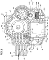
- FIG. 3 is a plan view of the rotating device according to the embodiment with a first casing being removed from the rotating device
- FIG. 4 is a diagram illustrating a horizontal sectional view of the rotating device according to the embodiment.
- FIG. 9 is a diagram illustrating a general configuration of an air-conditioning system including the rotating device according to the embodiment
- FIG. 10 is a diagram illustrating a vehicle including the air-conditioning system illustrated in FIG. 9 .
- This rotating device 1 is included in, for example, an air-conditioning system 100 for a vehicle installed in a vehicle 150 illustrated in FIG. 10 .
- the air-conditioning system 100 for a vehicle includes a blower fan 101, an evaporator 102 for cooling air delivered from the blower fan 101, and a heater 103 disposed downstream of the evaporator 102.
- a louver 104 configured to control an amount of air supplied from the evaporator 102 to the heater 103 is disposed between the evaporator 102 and the heater 103 to control an amount of supply of the air flowing from the evaporator 102 side toward the heater 103 side.
- the rotating device 1 rotates a drive shaft 104a of the louver 104.
- the rotating device 1 can control the rotational movement of the louver 104 configured to control, for example, the amount of air in the air-conditioning system 100.
- the rotating device 1 includes a casing 2 accommodating functional units.
- the functional units include, for example, a motor 3, a plurality of transmission gears 6, an output gear 5, and a sensor 7 and these functional units are described later.
- a direction in which a first casing 21 and a second casing 22 is joined is referred to as an up-down direction (positive and negative directions of a Z-axis).
- a longitudinal direction of a rotating shaft 31 of the motor 3 is referred to as a front-back direction (positive and negative directions of an X-axis).
- a direction orthogonal to the up-down direction and the front-back direction is referred to as a left-right direction (positive and negative directions of a Y-axis).
- the casing 2 is configured by joining the first casing 21 including an opening 214 and the second casing 22 including an opening 226 with the openings 214 and 226 facing each other.
- the casing 2 formed by joining the first casing 21 and the second casing 22 includes a top surface 2A, a bottom 2B, and a side wall 2C.
- the first casing 21 includes a first surface 210 serving as the top surface 2A of the casing 2, a first side wall 211 disposed along the outer circumference of the first surface 210, and the opening 214 defined by the first side wall 211.
- the second casing 22 includes a second surface 220 serving as the bottom 2B of the casing 2, a second side wall 222 disposed along the outer circumference of the second surface 220, and the opening 226.
- the first side wall 211 and the second side wall 222 form the side wall 2C of the casing 2.
- the casing 2 is made of a resin material such as polypropylene, polyethylene terephthalate, or ABS.
- the first casing 21 includes a plurality of fitting portions 212 integrally formed with the outer circumference of the first side wall 211, and the fitting portions 212 extend toward the second casing 22 side.
- the fitting portions 212 are provided with holes (hereinafter referred to as fitting holes 219).
- the second casing 22 includes a plurality of protrusions (hereinafter referred to as fitting protrusions 224) corresponding to the plurality of fitting portions 212 of the first casing 21 and integrally formed with the second side wall 222. These fitting protrusions 224 are fitted in the fitting holes 219 of the fitting portions 212.
- first casing 21 and the second casing 22 are joined such that the plurality of the fitting protrusions 224 of the second casing 22 are fitted in the fitting holes 219 of the plurality of fitting portions 212 of the first casing 21, and the first casing 21 and the second casing 22 are integrated to form the casing 2 ( FIG. 1 ) accommodating the functional units including various types of parts.
- the fitting portions 212 are included in the first casing 21 and the fitting protrusions 224 are included in the second casing 22, the fitting portions 212 may be included in the second casing 22 and the fitting protrusions 224 may be included in the first casing 21.
- the first casing 21 includes a plurality of (e.g., two) protrusions (not illustrated) at an inner surface of the first surface 210
- the second casing 22 includes, as illustrated in FIGS. 2 and 3 , a plurality of bosses 92 at an inner surface of the second surface 220 and the plurality of bosses 92 include through-holes corresponding to the plurality of protrusions.
- protrusions and through-holes provide a reference for joining the first casing 21 and the second casing 22 and allow for accurate positioning in the X and Y directions. Moreover, providing the protrusions fitted in the through-holes can increase the rigidity of the casing 2 and can prevent generation of abnormal noises. This configuration also prevents leaking of sounds generated inside the rotating device 1 through the through-holes.
- a protruding portion 213 and a protruding portion 223 corresponding to each other are formed on the first casing 21 and the second casing 22 .
- the protruding portions 213, 223 protrude in an extension direction of the rotating shaft 31 ( FIG. 2 ) of the motor 3.
- These protruding portions 213 and 223 are joined to form a connector 200 ( FIG. 1 ).
- the connector 200 accommodates a plurality of (three, in this example) first connection terminals 41 electrically connected to connection terminals (not illustrated) of a sensor 7 to be described later, and a plurality of (two, in this example) second connection terminals 42 electrically connected to motor terminals 33 of the motor 3 to be described later.
- the first casing 21 includes four mounting parts 215, 216, 217, 218 at the outer circumference for use in mounting the rotating device 1 to a predetermined position in, for example, an air-conditioning system.
- the rotating device 1 includes, as illustrated in FIGS. 2 and 3 , the motor 3, the output gear 5 that mechanically outputs rotation of the rotating shaft 31 of the motor 3 to an external device, the plurality of transmission gears 6 configured to transmit rotation of the motor 3 to the output gear 5, and the sensor 7 that detects the rotation angle of the output gear 5, as the various types of parts configuring the functional units accommodated in the casing 2.
- the sensor 7 includes a sensor unit 70 (see FIG. 6 ) and a case (hereinafter referred to as a sensor housing 72) accommodating the sensor unit 70.
- the rotating device 1 can control the rotation angle or the rotation rate of the motor 3 based on the rotation angle or the rotation rate of the output gear 5 detected by the sensor unit 70.
- the plurality of transmission gears 6 include a multi-step first transmission gear 61 and a multi-step second transmission gear 62. Since the plurality of gears mesh with each other, the rotation of the rotating shaft 31 of the motor 3 is transmitted to an output shaft 51 of the output gear 5.
- the rotating device 1 includes a flexible circuit board 8, and the circuit board 8 electrically connects the first connection terminals 41 with the motor 3 and the second connection terminals 42 with the sensor 7. Via the circuit board 8 and a connection terminals 40 (the first connection terminals 41 and the second connection terminals 42), input/output signals for driving the motor 3 and a signal corresponding to the rotation angle of the output gear 5 detected by the sensor 7 can be obtained from an external device.
- the term electrical connection includes a concept of directly connecting two members and a concept of connecting two members via other connection members.
- the circuit board is included in the concept of a connection member to be described later.
- the motor 3 is a drive device for rotating the output gear 5, and in the present embodiment, a direct-current (DC) motor is used as the motor 3.
- the motor 3 includes, as illustrated in FIG. 2 , an outer shell (frame) 32 including a rectangular prism outer shape with rounded corners and covering a main body of the motor 3, the rotating shaft 31, and a pair of motor terminals 33, 33.
- the outer shell 32 includes two side surfaces serving as a top surface and a bottom surface, and the two side surfaces are end surfaces at both of the opposite sides in the longitudinal direction of the rotating shaft 31.
- a first protrusion 321 is formed at the center of the top surface of the outer shell 32
- a second protrusion 322 is formed at the center of the bottom surface of the outer shell 32
- the rotating shaft 31 protrudes from the first protrusion 321 and the second protrusion 322 toward the side wall 2C of the casing 2 (second casing 22).
- the pair of motor terminals 33, 33 are disposed at the bottom surface of the outer shell 32 and face each other across the second protrusion 322.
- the rotating shaft 31 is rotatably supported by a plurality of supports included in the rotating device 1 and the details will be described later.
- the plurality of supports include: a first outer bearing 401 as a first support and a second outer bearing 402 as a second support that support, respectively, portions (both of end portions at opposite sides) 311, 312 of the rotating shaft 31 protruding from the outer shell 32; and a first inner bearing 410 and a second inner bearing 420 that support the rotating shaft 31 from inside the outer shell 32.
- the first outer bearing 401 as the first support and the second outer bearing 402 as the second support are disposed at the side wall 2C (the side wall 222 of the second casing 22) of the casing 2.
- the first outer bearing 401 and the second outer bearing 402 are held by the side wall 2C of the casing 2.
- Both of the portions of the rotating shaft 31 supported by the first outer bearing 401 as the first support and the second outer bearing 402 as the second support are the opposite end portions 311, 312 of the rotating shaft 31.
- a rotor 34 is fixed to a middle portion of the rotating shaft 31 while being slightly spaced apart from a stator 35.
- a worm gear 60 is mounted to a portion (end portion) of the rotating shaft 31 protruding from the first protrusion 321 of the outer shell 32, and the worm gear 60 is one of the transmission gears 6 to be described below.
- the transmission gears 6 are gears for transmitting rotation of the rotating shaft 31 of the motor 3 to the output gear 5 at a predetermined reduction ratio (gear ratio).
- the transmission gears 6 include the multi-step first transmission gear 61, the multi-step second transmission gear 62.
- the transmission gears may include the worm gear 60 mounted to the rotating shaft 31 of the motor 3.
- the transmission gears 6 include the first transmission gear 61 including a first large diameter portion 611 and a first small diameter portion 612 and the second transmission gear 62 including a second small diameter portion 621 and a second large diameter portion 622.
- the first large diameter portion 611 is formed to include a diameter larger than the diameter of the first small diameter portion 612.
- the relation between the second large diameter portion 622 and the second small diameter portion 621 is the same as the relation described above.
- the first large diameter portion 611 of the first transmission gear 61 meshes with the worm gear 60 mounted to the rotating shaft 31 of the motor 3.
- the first small diameter portion 612 of the first transmission gear 61 meshes with the second large diameter portion 622 of the second transmission gear 62, and the second small diameter portion 621 of the second transmission gear 62 meshes with the output gear 5.
- the meshing of the plurality of gears causes the rotation of the rotating shaft 31 of the motor 3 to be transmitted to the output shaft 51 of the output gear 5 at a predetermined reduction ratio.
- the two types of multi-step gears are used to transmit the rotation of the rotating shaft 31 of the motor 3 to the output gear 5 in a small space with an adjusted gear ratio
- the second transmission gear 62 may be, for example, eliminated so that the output gear 5 meshes with the first small diameter portion 612 including a small diameter of the first transmission gear 61, or both first transmission gear 61 and second transmission gear 62 may be eliminated so that the output gear 5 directly meshes with the worm gear 60.
- the output gear 5 includes a gear main body 5a including an outer circumferential surface formed with teeth 52 along the outer circumferential surface and a recess 50 recessed in the direction of the axis of rotation (the longitudinal direction of the output shaft 51 serving as the rotating shaft).
- the gear main body 5a includes a short tubular shape.
- the first transmission gear 61 and the second transmission gear 62 are multi-step gears.
- the second large diameter portion 622 of the second transmission gear 62 is disposed so as to partially overlap the output gear 5 and the first large diameter portion 611 of the first transmission gear 61 in the direction of the axis of rotation of the output gear 5 (see FIG. 3 ). Accordingly, the transmission gears 6 can be disposed in a compact space without increasing the size of the casing 2.
- a key fittable with a rotation plate 71 (see FIG. 6 ) included in the sensor 7 is formed at the upper end (one end) of the output shaft 51.
- the lower half of the output shaft 51 includes a diameter larger than the diameter of the upper half of the output shaft 51, and as illustrated in FIG. 4 , a fitting portion 54 fittable with an external shaft such as the drive shaft 104a of the louver 104 of the air-conditioning system 100 described above is formed at the inner circumferential surface of the output shaft 51. Accordingly, the rotation of the output gear 5 can control the rotational movement of the louver 104 and can adjust, for example, an amount of air of the air-conditioning system 100 (see FIG. 9 ).
- the drive shaft 104a of the louver 104 of the air-conditioning system 100 installed in, for example, a vehicle is connected to the output gear 5.
- the output gear 5 is a gear that outputs the rotational force of the rotating shaft 31 of the motor 3 as driving force for controlling the drive shaft 104a of the louver 104.
- the output gear 5 is not necessarily directly connected to a target shaft of rotation such as the drive shaft 104a of the louver 104.
- another gear member may be interposed between the rotating device 1 and a target shaft of rotation, and in this case, the rotating shaft of the interposed gear may be connected to the output gear 5.
- FIG. 6 is a diagram illustrating a sectional view of the sensor 7.
- the sensor 7 includes a sensor table 72c and the sensor unit 70 (see FIG. 6 ) mounted on the sensor table 72c.
- the sensor unit 70 includes a sensor board 73 disposed on the sensor table 72c, the first connection terminals 41 connected to a conductor portion (not illustrated) formed on the sensor board 73, the rotating plate 71 rotatable with the output gear 5, and a conductor brush 75 including bifurcated distal end 751 as a first end and base end 752 as a second end, the base end 752 being fixed to the rotating plate 71 so that the distal end 751 is in contact with the conductor portion on the sensor board 73.
- the sensor unit 70 is accommodated in a case (hereinafter referred to as the sensor housing 72).
- the the sensor housing 72 includes a circular shape when seen in the plan view, and includes a housing main body 72a accommodating the rotating plate 71 and a cover 72b including a rectangular shape when seen in the plan view and extending from the housing main body 72a toward the connection terminals 40.
- the rotating plate 71 includes a boss 711 disposed at the center of the rotating plate 71, and the housing main body 72a and the sensor table 72c each include a hole, and the boss 711 is inserted in the respective holes.
- the rotating device 1 can control the rotation of the motor 3 based on the rotation angle of the output gear 5 detected by the sensor 7 configured as described above.
- the sensor table 72c includes a substantial L-shape when seen in the plan view, and at a front portion of the sensor table 72c, three first connection terminals 41 are disposed close to the sensor board 73 and two second connection terminals 42 are disposed close to the motor 3.
- the three first connection terminals 41 and the two second connection terminals 42 are disposed sequentially.
- the sensor table 72c includes two holes 76, 76 disposed at a side of the front portion (a side portion close to the connector 200 in the illustrated example), and the sensor table 72c is fastened to the second casing 22 by screws or vis screws inserted in the holes 76, 76.
- the five connection terminals 40 include conductor portions 412, 422 respectively.
- the three first connection terminals 41 are connected to the sensor board 73 via the conductor portions 412.
- the two second connection terminals 42 are connected to the circuit board 8 via the conductor portions 422, and are connected to the motor 3 via the circuit board 8.
- FIG. 7 is a diagram illustrating the circuit board 8 connecting the second connection terminals 42 with the motor 3.
- the circuit board 8 is made of a flexible film, and includes, as illustrated in FIGS. 2 , 3 , and 7 , two large planar portions 81, 82. Specifically, the circuit board 8 includes a first planar portion 81 connected to the second connection terminals 42 and a second planar portion 82 connected to the motor terminals 33.
- the structure of the flexible circuit board 8 includes a film (resin board) including a thickness of, for example, about 12 ⁇ m to 50 ⁇ m, an adhesive layer deposited on the film, and a conductor including a thickness of, for example, about 12 ⁇ m to 50 ⁇ m printed or bonded on the adhesive layer.
- the film is made of an insulating resin material such as polyimide and polyester.
- the conductor is made of a metal material such as copper.
- the adhesive layer is made of epoxy resin or acrylic resin.
- the circuit board 8 is a flexible board restorable to the initial state after being bent at an angle equal to or larger than 90 degrees.
- holes 811 as the number of the second connection terminals 42 are provided at the first planar portion 81 of the flexible circuit board 8.
- the holes 811 are two and fitted with bent portions 421 formed at one end of each of the conductor portions 422 conductively connected to the second connection terminals 42. Fitting the bent portions 421 of the conductor portions 422 conductively connected to the first connection terminals 41 in the holes 811, 811 and, connecting by, for example, soldering can make more secure electrical connection and can prevent electrical contact failure.
- the second planar portion 82 includes a pair of holes 821, 821 fittable with the pair of motor terminals 33, 33. Fitting the motor terminals 33, 33 in the holes 821, 821 and connecting by soldering can make more secure electrical connection.
- the second connection terminals 42 are connected to the motor 3 via the flexible circuit board 8, and when, for example, vibration of a vehicle such as an automobile vibrates the second connection terminals 42, the flexible circuit board 8 changes the shape (or absorbs the vibration) before a large stress is applied to the electrically connected portions such as soldered joints, and the amplitude of the vibration is reduced. Accordingly, application of a large stress to the connected portions can be prevented so that cracks or damages on the connected portions can be prevented.
- the flexible circuit board 8 is used to electrically connect the second connection terminals 42 with the motor 3, and using the flexible circuit board 8 is easier to handle and is more advantageous in terms of manufacturing costs than using, for example, thin, fragile leads.
- FIG. 5 is a sectional view illustrating a partially omitted support structure for the rotating shaft 31 of the motor 3.
- a rotating shaft such as a rotating shaft of a typical DC motor, protruding from a main body with an end being a free end is provided with a worm gear and the worm gear meshes with a transmission gear.
- the rotating shaft is supported at one end and the rotating shaft is subjected to side pressure due to the reaction force from the gear meshing with the worm gear.
- This structure may generate unexpected vibrations, and accordingly, may impair quietness and generate an abnormal noise.
- the rotating shaft 31 of the motor 3 according to the present embodiment is rotatably supported by a plurality of supports included in the rotating device 1.
- the plurality of supports according to the present embodiment are the first outer bearing 401 as the first support, the second outer bearing 402 as the second support, and the first inner bearing 410 and the second inner bearing 420.
- the first outer bearing 401 and the second outer bearing 402 are made of a resin material and include a cap shape (including a tubular outer circumferential surface with an end in the longitudinal direction of the rotating shaft being a bottom and the other end being an opening).
- the first outer bearing 401 and the second outer bearing 402 are provided to surround and support the end portions 311, 312 of the rotating shaft 31 protruding from the outer shell 32 of the motor 3.
- the first outer bearing 401 and the second outer bearing 402 can receive force applied to both of the end portions 311, 312 of the rotating shaft 31 of the motor 3 both in the axial direction and in the direction (radial direction) orthogonal to the axial direction.
- the worm gear 60 is mounted to the rotating shaft 31 of the motor 3 in the rotating device 1, between the one end portion 311 protruding from the outer shell 32 and the first protrusion 321 disposed at the center of the top surface of the outer shell 32.
- the worm gear 60 meshes with the first large diameter portion 611 of the first transmission gear 61.
- both of the end portions 311, 312 of the rotating shaft 31 of the motor 3 are supported by the first outer bearing 401 and the second outer bearing 402, respectively. Accordingly, the rotating shaft 31 can be configured as a double supported shaft, and this configuration can significantly reduce the vibration of the rotating shaft 31 and also reduce the vibration of the casing 2 caused by the vibration of the rotating shaft 31.
- the rotating device 1 To hold the cap-shaped first outer bearing 401 and second outer bearing 402, the rotating device 1 according to the present embodiment includes a first fitting portion 225a and a second fitting portion 225b formed on the casing 2 as illustrated in FIGS. 3 to 5 .
- the first fitting portion 225a and the second fitting portion 225b include the same shape, and the first fitting portion 225a is formed by recesses (hereinafter referred to as fitting recesses 2251, 2252) abutting each other and formed, respectively, in the first casing 21 and the second casing 22 facing each other to configure the casing 2.
- the second fitting portion 225b is formed by fitting recesses 2253, 2254 abutting each other and formed, respectively, in the first casing 21 and the second casing 22.
- the first casing 21 includes a pair of fitting recesses 2251, 2253 corresponding to the first outer bearing 401 and the second outer bearing 402, respectively
- the second casing 22 includes a pair of fitting recesses 2252, 2254 corresponding to the first outer bearing 401 and the second outer bearing 402, respectively.
- the fitting recesses 2251, 2252 abut each other to form the first fitting portion 225a and the fitting recesses 2253, 2254 abut each other to form the second fitting portion 225b.
- the structure for holding the first outer bearing 401 and the second outer bearing 402 can be easily provided by joining the first casing 21 and the second casing 22. Accordingly, the rotating device 1 can be assembled more easily in the manufacturing process.
- the first inner bearing 410 and the second inner bearing 420 are provided to support the rotating shaft 31 in the outer shell 32, and are plain bearing made of a metal material (sintered material) what is called "metal”.
- first inner bearing 410 is disposed in the first protrusion 321 formed at the center of the top surface of the outer shell 32 and the second inner bearing 420 is disposed in the second protrusion 322 formed at the center of the bottom surface of the outer shell 32.
- bearing holders corresponding to the first inner bearing 410 and the second inner bearing 420 are formed in the outer shell 32, and the rotating shaft 31 can be supported more securely.
- the configuration of the rotating device 1 according to the present embodiment can reduce the vibration of the rotating shaft 31 and thus can reduce the vibrating sound of the rotating device 1.
- the rotating device 1 can be suitably included in, for example, the air-conditioning system 100 for a vehicle (see FIG. 9 ) requiring quietness.
- the worm gear 60 mounted to the rotating shaft 31 is disposed between the first protrusion 321 and the first outer bearing 401 and this disposition facilitates accurate positioning. Accordingly, improved positioning accuracy can reduce noises from the worm gear 60 and the first transmission gear 61 meshing with the worm gear 60, and can prevent jumping of the worm gear 60.
- the configuration above can reduce vibration caused by frictions between the first inner bearing 410 and the second inner bearing 420 and the rotating shaft 31 of the motor 3 when side pressure is applied, and can reduce noise emitted from the rotating device 1 generated by the vibration.
- the rotating shaft 31 of the motor 3 is configured as a double supported shaft, the load on the first inner bearing 410 and the second inner bearing 420 is reduced, and thus, failures attributed to the first inner bearing 410 and the second inner bearing 420 can be prevented and an increase in the durability of the motor 3 can be expected.
- the main body of the motor 3 included in the rotating device 1 according to the present embodiment is covered by the outer shell 32 including a rectangular prism outer shape with rounded corners.
- the motor 3 is accommodated in the casing 2 such that the outer shell 32 is held by the casing 2 via an elastic member 430 including viscosity.
- the second casing 22 configuring a half part of the casing 2 includes a motor accommodating portion 227 for accommodating a major part of the motor 3.
- the motor 3 is disposed in the motor accommodating portion 227 such that a plurality of the elastic members 430 appropriately spaced apart from each other are interposed between a wall surface defining the motor accommodating portion 227 and the outer shell 32 of the motor 3.
- the outer shell 32 of the motor 3 Since the outer shell 32 of the motor 3 is severely vibrated by electromagnetic force, the outer shell 32 is configured not to directly contact the casing 2. Accordingly, this configuration prevents transmission of vibration (noise) of the motor 3 and improves the quietness of the rotating device 1.
- the elastic members 430 can be made of, for example, a UV curable gel or a two-part composition curable gel. Alternatively, the elastic members 430 may be made of the UV curable gel and the two-part composition curable gel, as appropriate.
- the structure for holding the motor 3 in the casing 2 via the elastic members 430 as cushion members is implemented by a few drops of either the UV curable gel or the two-part composition curable gel in the gap between the outer shell 32 of the motor 3 and the wall surface of the casing 2.
- the sensor 7 included in the rotating device 1 described above is configured such that the sensor board 73 and the conductor brush 75 configuring the sensor unit 70 are accommodated in the sensor housing 72.
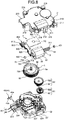
- FIG. 8 is an exploded perspective view of a rotating device 1 according to a modification.
- the rotating device 1 according to the modification differs from the embodiment as described above in that the rotating device 1 according to the modification includes a sensor board 700, connection terminals 45, and a circuit board 800, and the other configurations are given the same reference signs as those used in the embodiment above and the description of the other configurations are omitted.
- the sensor 7 of the rotating device 1 includes the sensor board 700 including a rectangular shape and disposed above the output gear 5.
- the sensor board 700 includes a hole 710 and the output shaft 51 of the output gear 5 is inserted into the hole 710.
- the conductor brush 75 is disposed in the recess 50 formed in the output gear 5 in the direction of the axis of rotation.
- a pair of brush mounting parts 754 are formed at the bottom surface of the recess 50 of the output gear 5, and the base end 752 of the conductor brush 75 is attached to the brush mounting parts 754, and the distal end 751 is in contact with a conductor portion formed on a back surface of the sensor board 700, that is, a surface facing the output gear 5.
- the rotating device 1 includes the connection terminals 45 electrically connecting the motor 3 and the sensor 7 to the outside, and the connection terminals 45 include uniformly shaped three sensor connection terminals 43 and two motor connection terminals 44.
- connection terminals 45 each include a terminal portion 40b extending in the same direction as the direction of the connector 200 protruding from the casing 2 and include a connection tip 40a opposite to the terminal portion 40b and protruding upward.
- the circuit board 800 includes a first planar portion 810 connected to the sensor connection terminals 43, a second planar portion 820 connected to the motor terminals 33, and a middle planar portion 830 connecting the first planar portion 810 with the second planar portion 820.
- the circuit board 800 according to the present embodiment is made of a flexible material same as the material of the circuit board 8 described in the embodiment above.
- connection tips 40a of the connection terminals 45 are inserted in holes 812 formed in the first planar portion 810 of the circuit board 800. Accordingly, the three sensor connection terminals 43 are electrically connected to the sensor board 700 and the two motor connection terminals 44 are electrically connected to the motor 3.
- the rotating device 1 includes a structure for supporting the rotating shaft 31 of the motor 3 by the first outer bearing 401 and the second outer bearing 402, and by the first inner bearing 410 and the second inner bearing 420, and thus the rotating shaft 31 is configured as a double supported shaft. Accordingly, the vibration of the rotating shaft 31 is reduced and, for example, vibrating sound of the rotating device 1 can be reduced.
- the rotating shaft 31 of the motor 3 is supported by supports including the first outer bearing 401 and the second outer bearing 402, and the first inner bearing 410 and the second inner bearing 420.
- first outer bearing 401 and the second outer bearing 402 is not necessarily cap-shaped members made of a resin material.
- the end portions 311, 312 at both of the opposite ends of the rotating shaft 31 protruding from the outer shell 32 may be directly supported by the casing 2.
- first fitting portion 225a and the second fitting portion 225b illustrated in FIG. 5 may include a shape corresponding, respectively, to the end portions 311, 312 at both of the opposite ends of the rotating shaft 31, not including a shape corresponding, respectively, to the cap-shaped first outer bearing 401 and second outer bearing 402.
- the first support and the second support surrounding and supporting both of the end portions 311, 312 of the rotating shaft 31 are formed in the casing 2.
- the rotating shaft 31 is configured as a double supported shaft, and thus, vibration of the rotating shaft 31 is reduced. Accordingly, for example, the vibrating sound of the rotating device 1 can be reduced.
- bearings such as metal bearings, and the number of parts can be reduced and accordingly, the weight and manufacturing costs can be reduced.
- a rotating device 1 to be described below can be implemented.
- the rotating device 1 including the motor 3 including the outer shell 32, the rotating shaft 31 protruding from the outer shell 32, the first inner bearing 410 supporting the rotating shaft 31, and the second inner bearing 420 supporting the rotating shaft 31, the transmission gears 6 and the output gear 5 configured to transmit rotation of the motor 3 to an external device, and the casing 2, wherein a first outer bearing 401 and a second outer bearing 402 are arranged at the casing 2, and the first outer bearing 401 and the second outer bearing 402 rotatably support portions of the rotating shaft 31 protruding from end surfaces at both sides of the outer shell 32 in a longitudinal direction of the rotating shaft 31.
- This configuration of the rotating device 1 can reduce the vibration of the rotating shaft 31 and thus can reduce, for example, the vibrating sound of the rotating device 1.
- the rotating device 1 can be suitably included in, for example, an air-conditioning system 100 for a vehicle requiring quietness.
- This configuration of the rotating device 1 can reduce the vibration of the rotating shaft 31 more effectively and can reduce, for example, vibrating sound.
- This configuration of the rotating device 1 can securely support the rotating shaft 31 of the motor 3 at both of the opposite ends if, for example, the casing 2 is made of, for example, a resin containing glass fibers.
- This configuration of the rotating device 1 need not include a special bearing structure and the manufacturing costs can be reduced.
- the casing 2 includes the first casing 21 including the plurality of recesses (fitting recesses 2251, 2253) and the second casing 22 including the plurality of recesses (fitting recesses 2252, 2254), the first casing 21 and the second casing 22 opposing each other, and the two pairs of recesses (the fitting recess 2251 and the fitting recess 2252, and the fitting recess 2253 and the fitting recess 2254) opposing each other hold the first outer bearing 401 and the second outer bearing 402.
- This configuration of the rotating device 1 can easily hold the first outer bearing 401 and the second outer bearing 402 by joining the first casing 21 and the second casing 22, and facilitates the assembling process of the rotating device 1.
- the rotating device 1 according to any one of (1) to (5), wherein the outer shell 32 includes the first protrusion 321 at a top surface being one of the end surfaces on both sides of the outer shell 32 in the longitudinal direction of the rotating shaft 31, and includes the second protrusion 322 at a bottom surface being the other end surface of the outer shell 32, and the first inner bearing 410 is arranged at the first protrusion 321 and the second inner bearing 420 is arranged at the second protrusion 322.
- This configuration of the rotating device 1 can use the first protrusion 321 and the second protrusion 322 formed on the outer shell 32 as bearing holders corresponding to the first inner bearing 410 and the second inner bearing 420, and the rotating shaft 31 can be supported more securely.
- the rotating device 1 according to any one of (1) to (6) further including the worm gear 60 mounted to a portion of the rotating shaft 31 protruding from one of the end surfaces of the outer shell 32, wherein the worm gear 60 is arranged between the first inner bearing 410 and the first outer bearing 401.
- This configuration of the rotating device 1 disposes the worm gear 60 between the first protrusion 321 and the first outer bearing 401, and thus facilitates accurate positioning. Accordingly, improved positioning accuracy can reduce noises from the worm gear 60 and the first transmission gear 61 meshing with the worm gear 60. In addition, the improved positioning accuracy can prevent jumping of the worm gear 60.
- This configuration of the rotating device 1 prevents the outer shell 32 of the motor 3 subjected to severe vibration caused by the electromagnetic force from directly contacting the casing 2, and thus prevents transmission of vibration (noises) from the motor 3 and improves quietness of the rotating device 1.
- This configuration of the rotating device 1 eliminates the need for an elastic member 430 made of a special material, and thus can improve quietness of the rotating device 1 without increasing manufacturing costs.
Landscapes
- Engineering & Computer Science (AREA)
- General Engineering & Computer Science (AREA)
- Mechanical Engineering (AREA)
- Power Engineering (AREA)
- Connection Of Motors, Electrical Generators, Mechanical Devices, And The Like (AREA)
- Motor Or Generator Frames (AREA)
- Gear Transmission (AREA)
- Sliding-Contact Bearings (AREA)
Abstract
Description
- The present invention relates to a rotating device.
- Conventionally, a drive device (rotating device) including a motor and a gear for transmitting rotation of the motor to the outside is known, and the drive device can drive, for example, a valve and a switching door (louver) of a vehicle air-conditioner system (see
Patent Literature 1 and Patent Literature 2). -
- Patent Literature 1: Japanese Utility Model Application Laid-open No.
07-167330 - Patent Literature 2: Japanese Laid-open Patent Publication No.
2013-005512 - However, inner environment of the recently developed vehicles is becoming quieter, and it is considered that, for example, further quietness is required for components including a motor than ever before.
- The present invention has been made in view of the foregoing as an example problem to be solved, and it is an object of the present invention to provide a rotating device capable of reducing, for example, vibrating sound.
- It is an object of the present invention to at least partially solve the problems in the conventional technology. A rotating device according to the present invention includes a motor including an outer shell, a rotating shaft protruding from the outer shell, a first inner bearing supporting the rotating shaft, and a second inner bearing supporting the rotating shaft, a plurality of gears configured to transmit rotation of the motor to an external device, and a casing. A first outer bearing and a second outer bearing are arranged at the casing, and the first outer bearing and the second outer bearing rotatably support portions of the rotating shaft protruding from end surfaces at both sides of the outer shell in a longitudinal direction of the rotating shaft.
- According to an embodiment of the present invention, a rotating device capable of reducing, for example, vibrating sound can be provided.
-
-
FIG. 1 is a perspective view of a rotating device according to an embodiment. -
FIG. 2 is an exploded perspective view of the rotating device according to the embodiment. -
FIG. 3 is a plan view of the rotating device according to the embodiment with a first casing being removed from the rotating device. -
FIG. 4 is a diagram illustrating a horizontal sectional view of the rotating device according to the embodiment. -
FIG. 5 is a sectional view illustrating a partially omitted support structure for a rotating shaft of a motor. -
FIG. 6 is a diagram illustrating a sectional view of a sensor. -
FIG. 7 is a diagram illustrating a circuit board connecting second connection terminals with the motor. -
FIG. 8 is an exploded perspective view of a rotating device according to a modification. -
FIG. 9 is a diagram illustrating a general configuration of an air-conditioning system including the rotating device according to the embodiment. -
FIG. 10 is a diagram illustrating a vehicle including the air-conditioning system illustrated inFIG. 9 . - The following describes modes (hereinafter, called "embodiments") for carrying out the present invention will be described in detail based on the accompanying drawings. The same components are denoted by the same reference signs throughout the description of the embodiments.
-
FIG. 1 is a perspective view of a rotating device according to an embodiment, andFIG. 2 is an exploded perspective view of the rotating device according to the embodiment.FIG. 3 is a plan view of the rotating device according to the embodiment with a first casing being removed from the rotating device, andFIG. 4 is a diagram illustrating a horizontal sectional view of the rotating device according to the embodiment.FIG. 9 is a diagram illustrating a general configuration of an air-conditioning system including the rotating device according to the embodiment, andFIG. 10 is a diagram illustrating a vehicle including the air-conditioning system illustrated inFIG. 9 . - This
rotating device 1 according to the embodiment is included in, for example, an air-conditioning system 100 for a vehicle installed in avehicle 150 illustrated inFIG. 10 . As illustrated inFIG. 9 , the air-conditioning system 100 for a vehicle includes ablower fan 101, anevaporator 102 for cooling air delivered from theblower fan 101, and aheater 103 disposed downstream of theevaporator 102. Alouver 104 configured to control an amount of air supplied from theevaporator 102 to theheater 103 is disposed between theevaporator 102 and theheater 103 to control an amount of supply of the air flowing from theevaporator 102 side toward theheater 103 side. Therotating device 1 rotates adrive shaft 104a of thelouver 104. Therotating device 1 can control the rotational movement of thelouver 104 configured to control, for example, the amount of air in the air-conditioning system 100. - As illustrated in
FIGS. 1 and2 , therotating device 1 includes acasing 2 accommodating functional units. Specifically, the functional units include, for example, amotor 3, a plurality of transmission gears 6, anoutput gear 5, and asensor 7 and these functional units are described later. - In the description below, for ease of description, a direction in which a
first casing 21 and asecond casing 22 is joined is referred to as an up-down direction (positive and negative directions of a Z-axis).A longitudinal direction of arotating shaft 31 of themotor 3 is referred to as a front-back direction (positive and negative directions of an X-axis). And a direction orthogonal to the up-down direction and the front-back direction is referred to as a left-right direction (positive and negative directions of a Y-axis). - The
casing 2 is configured by joining thefirst casing 21 including an opening 214 and thesecond casing 22 including anopening 226 with theopenings casing 2 formed by joining thefirst casing 21 and thesecond casing 22 includes atop surface 2A, abottom 2B, and aside wall 2C. When the positional relation between an upper side and a lower side is described in the description below, the reference state of therotating device 1 is such that thefirst casing 21 is relatively at the upper side and thesecond casing 22 is relatively at the lower side. - The
first casing 21 includes afirst surface 210 serving as thetop surface 2A of thecasing 2, afirst side wall 211 disposed along the outer circumference of thefirst surface 210, and theopening 214 defined by thefirst side wall 211. Thesecond casing 22 includes asecond surface 220 serving as thebottom 2B of thecasing 2, asecond side wall 222 disposed along the outer circumference of thesecond surface 220, and theopening 226. Thefirst side wall 211 and thesecond side wall 222 form theside wall 2C of thecasing 2. Thecasing 2 is made of a resin material such as polypropylene, polyethylene terephthalate, or ABS. - The
first casing 21 includes a plurality offitting portions 212 integrally formed with the outer circumference of thefirst side wall 211, and thefitting portions 212 extend toward thesecond casing 22 side. Thefitting portions 212 are provided with holes (hereinafter referred to as fitting holes 219). Thesecond casing 22 includes a plurality of protrusions (hereinafter referred to as fitting protrusions 224) corresponding to the plurality offitting portions 212 of thefirst casing 21 and integrally formed with thesecond side wall 222. Thesefitting protrusions 224 are fitted in the fittingholes 219 of thefitting portions 212. - In other words, the
first casing 21 and thesecond casing 22 are joined such that the plurality of thefitting protrusions 224 of thesecond casing 22 are fitted in thefitting holes 219 of the plurality offitting portions 212 of thefirst casing 21, and thefirst casing 21 and thesecond casing 22 are integrated to form the casing 2 (FIG. 1 ) accommodating the functional units including various types of parts. - Although, in the present embodiment, the
fitting portions 212 are included in thefirst casing 21 and thefitting protrusions 224 are included in thesecond casing 22, thefitting portions 212 may be included in thesecond casing 22 and thefitting protrusions 224 may be included in thefirst casing 21. - The
first casing 21 includes a plurality of (e.g., two) protrusions (not illustrated) at an inner surface of thefirst surface 210, and thesecond casing 22 includes, as illustrated inFIGS. 2 and3 , a plurality ofbosses 92 at an inner surface of thesecond surface 220 and the plurality ofbosses 92 include through-holes corresponding to the plurality of protrusions. When thefirst casing 21 and thesecond casing 22 abut each other and are joined to form a unitary structure, each of the protrusions is pushed and fitted in each of the through-holes. These protrusions and through-holes extend in the direction of the axis of rotation of the transmission gears 6 or theoutput gear 5. - These two pairs of protrusions and through-holes provide a reference for joining the
first casing 21 and thesecond casing 22 and allow for accurate positioning in the X and Y directions. Moreover, providing the protrusions fitted in the through-holes can increase the rigidity of thecasing 2 and can prevent generation of abnormal noises. This configuration also prevents leaking of sounds generated inside therotating device 1 through the through-holes. - As illustrated in
FIGS. 1 and2 , on thefirst casing 21 and thesecond casing 22, aprotruding portion 213 and aprotruding portion 223 corresponding to each other are formed. In the present embodiment, theprotruding portions FIG. 2 ) of themotor 3. Theseprotruding portions FIG. 1 ). - As illustrated in
FIG. 3 , theconnector 200 accommodates a plurality of (three, in this example)first connection terminals 41 electrically connected to connection terminals (not illustrated) of asensor 7 to be described later, and a plurality of (two, in this example)second connection terminals 42 electrically connected tomotor terminals 33 of themotor 3 to be described later. - As illustrated in
FIGS. 1 and2 , thefirst casing 21 includes four mountingparts rotating device 1 to a predetermined position in, for example, an air-conditioning system. - The
rotating device 1 includes, as illustrated inFIGS. 2 and3 , themotor 3, theoutput gear 5 that mechanically outputs rotation of therotating shaft 31 of themotor 3 to an external device, the plurality of transmission gears 6 configured to transmit rotation of themotor 3 to theoutput gear 5, and thesensor 7 that detects the rotation angle of theoutput gear 5, as the various types of parts configuring the functional units accommodated in thecasing 2. Thesensor 7 includes a sensor unit 70 (seeFIG. 6 ) and a case (hereinafter referred to as a sensor housing 72) accommodating thesensor unit 70. Therotating device 1 can control the rotation angle or the rotation rate of themotor 3 based on the rotation angle or the rotation rate of theoutput gear 5 detected by thesensor unit 70. - The plurality of transmission gears 6 include a multi-step
first transmission gear 61 and a multi-stepsecond transmission gear 62. Since the plurality of gears mesh with each other, the rotation of therotating shaft 31 of themotor 3 is transmitted to anoutput shaft 51 of theoutput gear 5. - As illustrated in
FIGS. 2 and3 , therotating device 1 according to the present embodiment includes aflexible circuit board 8, and thecircuit board 8 electrically connects thefirst connection terminals 41 with themotor 3 and thesecond connection terminals 42 with thesensor 7. Via thecircuit board 8 and a connection terminals 40 (thefirst connection terminals 41 and the second connection terminals 42), input/output signals for driving themotor 3 and a signal corresponding to the rotation angle of theoutput gear 5 detected by thesensor 7 can be obtained from an external device. In this description, the term electrical connection includes a concept of directly connecting two members and a concept of connecting two members via other connection members. The circuit board is included in the concept of a connection member to be described later. - The following more specifically describes elements configuring the functional units.
- The
motor 3 is a drive device for rotating theoutput gear 5, and in the present embodiment, a direct-current (DC) motor is used as themotor 3. Themotor 3 includes, as illustrated inFIG. 2 , an outer shell (frame) 32 including a rectangular prism outer shape with rounded corners and covering a main body of themotor 3, the rotatingshaft 31, and a pair ofmotor terminals outer shell 32 includes two side surfaces serving as a top surface and a bottom surface, and the two side surfaces are end surfaces at both of the opposite sides in the longitudinal direction of therotating shaft 31. - A
first protrusion 321 is formed at the center of the top surface of theouter shell 32, and asecond protrusion 322 is formed at the center of the bottom surface of theouter shell 32, and therotating shaft 31 protrudes from thefirst protrusion 321 and thesecond protrusion 322 toward theside wall 2C of the casing 2 (second casing 22). The pair ofmotor terminals outer shell 32 and face each other across thesecond protrusion 322. - As illustrated in
FIG. 4 , the rotatingshaft 31 is rotatably supported by a plurality of supports included in therotating device 1 and the details will be described later. The plurality of supports include: a firstouter bearing 401 as a first support and a secondouter bearing 402 as a second support that support, respectively, portions (both of end portions at opposite sides) 311, 312 of therotating shaft 31 protruding from theouter shell 32; and a firstinner bearing 410 and a secondinner bearing 420 that support the rotatingshaft 31 from inside theouter shell 32. - The first
outer bearing 401 as the first support and the secondouter bearing 402 as the second support are disposed at theside wall 2C (theside wall 222 of the second casing 22) of thecasing 2. The firstouter bearing 401 and the secondouter bearing 402 are held by theside wall 2C of thecasing 2. Both of the portions of therotating shaft 31 supported by the firstouter bearing 401 as the first support and the secondouter bearing 402 as the second support are theopposite end portions rotating shaft 31. - Inside the main body of the
motor 3, arotor 34 is fixed to a middle portion of therotating shaft 31 while being slightly spaced apart from astator 35. Aworm gear 60 is mounted to a portion (end portion) of therotating shaft 31 protruding from thefirst protrusion 321 of theouter shell 32, and theworm gear 60 is one of the transmission gears 6 to be described below. - The transmission gears 6 are gears for transmitting rotation of the
rotating shaft 31 of themotor 3 to theoutput gear 5 at a predetermined reduction ratio (gear ratio). In the present embodiment, as described above, the transmission gears 6 include the multi-stepfirst transmission gear 61, the multi-stepsecond transmission gear 62. The transmission gears may include theworm gear 60 mounted to therotating shaft 31 of themotor 3. - As illustrated in
FIG. 2 , the transmission gears 6 include thefirst transmission gear 61 including a firstlarge diameter portion 611 and a firstsmall diameter portion 612 and thesecond transmission gear 62 including a secondsmall diameter portion 621 and a secondlarge diameter portion 622. The firstlarge diameter portion 611 is formed to include a diameter larger than the diameter of the firstsmall diameter portion 612. The relation between the secondlarge diameter portion 622 and the secondsmall diameter portion 621 is the same as the relation described above. - The first
large diameter portion 611 of thefirst transmission gear 61 meshes with theworm gear 60 mounted to therotating shaft 31 of themotor 3. The firstsmall diameter portion 612 of thefirst transmission gear 61 meshes with the secondlarge diameter portion 622 of thesecond transmission gear 62, and the secondsmall diameter portion 621 of thesecond transmission gear 62 meshes with theoutput gear 5. In this way, the meshing of the plurality of gears causes the rotation of therotating shaft 31 of themotor 3 to be transmitted to theoutput shaft 51 of theoutput gear 5 at a predetermined reduction ratio. - In the present embodiment, the two types of multi-step gears, the
first transmission gear 61 and thesecond transmission gear 62, are used to transmit the rotation of therotating shaft 31 of themotor 3 to theoutput gear 5 in a small space with an adjusted gear ratio, however, in a possible design, thesecond transmission gear 62 may be, for example, eliminated so that theoutput gear 5 meshes with the firstsmall diameter portion 612 including a small diameter of thefirst transmission gear 61, or bothfirst transmission gear 61 andsecond transmission gear 62 may be eliminated so that theoutput gear 5 directly meshes with theworm gear 60. - As illustrated in
FIG. 2 , theoutput gear 5 includes a gearmain body 5a including an outer circumferential surface formed withteeth 52 along the outer circumferential surface and arecess 50 recessed in the direction of the axis of rotation (the longitudinal direction of theoutput shaft 51 serving as the rotating shaft). The gearmain body 5a includes a short tubular shape. - As described above, the
first transmission gear 61 and thesecond transmission gear 62 are multi-step gears. The secondlarge diameter portion 622 of thesecond transmission gear 62 is disposed so as to partially overlap theoutput gear 5 and the firstlarge diameter portion 611 of thefirst transmission gear 61 in the direction of the axis of rotation of the output gear 5 (seeFIG. 3 ). Accordingly, the transmission gears 6 can be disposed in a compact space without increasing the size of thecasing 2. - A key fittable with a rotation plate 71 (see
FIG. 6 ) included in thesensor 7 is formed at the upper end (one end) of theoutput shaft 51. The lower half of theoutput shaft 51 includes a diameter larger than the diameter of the upper half of theoutput shaft 51, and as illustrated inFIG. 4 , afitting portion 54 fittable with an external shaft such as thedrive shaft 104a of thelouver 104 of the air-conditioning system 100 described above is formed at the inner circumferential surface of theoutput shaft 51. Accordingly, the rotation of theoutput gear 5 can control the rotational movement of thelouver 104 and can adjust, for example, an amount of air of the air-conditioning system 100 (seeFIG. 9 ). - As described above, the
drive shaft 104a of thelouver 104 of the air-conditioning system 100 installed in, for example, a vehicle is connected to theoutput gear 5. In other words, theoutput gear 5 is a gear that outputs the rotational force of therotating shaft 31 of themotor 3 as driving force for controlling thedrive shaft 104a of thelouver 104. However, theoutput gear 5 is not necessarily directly connected to a target shaft of rotation such as thedrive shaft 104a of thelouver 104. For example, another gear member may be interposed between therotating device 1 and a target shaft of rotation, and in this case, the rotating shaft of the interposed gear may be connected to theoutput gear 5. - As described above, to drive the
louver 104 included in, for example, the air-conditioning system 100 (seeFIG. 9 ) to a predetermined state, the rotation angle of theoutput gear 5 can be detected by thesensor 7. Thesensor 7 is described with reference toFIGS. 2 ,3 , and6. FIG. 6 is a diagram illustrating a sectional view of thesensor 7. - As illustrated in
FIGS. 2 ,3 , and6 , thesensor 7 includes a sensor table 72c and the sensor unit 70 (seeFIG. 6 ) mounted on the sensor table 72c. - The
sensor unit 70 includes asensor board 73 disposed on the sensor table 72c, thefirst connection terminals 41 connected to a conductor portion (not illustrated) formed on thesensor board 73, the rotatingplate 71 rotatable with theoutput gear 5, and aconductor brush 75 including bifurcateddistal end 751 as a first end andbase end 752 as a second end, thebase end 752 being fixed to therotating plate 71 so that thedistal end 751 is in contact with the conductor portion on thesensor board 73. - The
sensor unit 70 is accommodated in a case (hereinafter referred to as the sensor housing 72). The thesensor housing 72 includes a circular shape when seen in the plan view, and includes a housingmain body 72a accommodating therotating plate 71 and acover 72b including a rectangular shape when seen in the plan view and extending from the housingmain body 72a toward theconnection terminals 40. As illustrated inFIG. 6 , the rotatingplate 71 includes aboss 711 disposed at the center of therotating plate 71, and the housingmain body 72a and the sensor table 72c each include a hole, and theboss 711 is inserted in the respective holes. - The
rotating device 1 can control the rotation of themotor 3 based on the rotation angle of theoutput gear 5 detected by thesensor 7 configured as described above. - As illustrated in
FIGS. 2 and3 , the sensor table 72c includes a substantial L-shape when seen in the plan view, and at a front portion of the sensor table 72c, threefirst connection terminals 41 are disposed close to thesensor board 73 and twosecond connection terminals 42 are disposed close to themotor 3. The threefirst connection terminals 41 and the twosecond connection terminals 42 are disposed sequentially. The sensor table 72c includes twoholes connector 200 in the illustrated example), and the sensor table 72c is fastened to thesecond casing 22 by screws or vis screws inserted in theholes - The five
connection terminals 40 includeconductor portions first connection terminals 41 are connected to thesensor board 73 via theconductor portions 412. The twosecond connection terminals 42 are connected to thecircuit board 8 via theconductor portions 422, and are connected to themotor 3 via thecircuit board 8. - The two
second connection terminals 42 disposed at the sensor table 72c are connected to themotor 3 via thecircuit board 8.FIG. 7 is a diagram illustrating thecircuit board 8 connecting thesecond connection terminals 42 with themotor 3. - The
circuit board 8 is made of a flexible film, and includes, as illustrated inFIGS. 2 ,3 , and7 , two largeplanar portions circuit board 8 includes a firstplanar portion 81 connected to thesecond connection terminals 42 and a secondplanar portion 82 connected to themotor terminals 33. - The structure of the
flexible circuit board 8 includes a film (resin board) including a thickness of, for example, about 12 µm to 50 µm, an adhesive layer deposited on the film, and a conductor including a thickness of, for example, about 12 µm to 50 µm printed or bonded on the adhesive layer. The film is made of an insulating resin material such as polyimide and polyester. The conductor is made of a metal material such as copper. The adhesive layer is made of epoxy resin or acrylic resin. Thecircuit board 8 is a flexible board restorable to the initial state after being bent at an angle equal to or larger than 90 degrees. - As
many holes 811 as the number of thesecond connection terminals 42 are provided at the firstplanar portion 81 of theflexible circuit board 8. Theholes 811 are two and fitted withbent portions 421 formed at one end of each of theconductor portions 422 conductively connected to thesecond connection terminals 42. Fitting thebent portions 421 of theconductor portions 422 conductively connected to thefirst connection terminals 41 in theholes - As illustrated in
FIG. 7 , the secondplanar portion 82 includes a pair ofholes motor terminals motor terminals holes - As described above, the
second connection terminals 42 are connected to themotor 3 via theflexible circuit board 8, and when, for example, vibration of a vehicle such as an automobile vibrates thesecond connection terminals 42, theflexible circuit board 8 changes the shape (or absorbs the vibration) before a large stress is applied to the electrically connected portions such as soldered joints, and the amplitude of the vibration is reduced. Accordingly, application of a large stress to the connected portions can be prevented so that cracks or damages on the connected portions can be prevented. - The
flexible circuit board 8 is used to electrically connect thesecond connection terminals 42 with themotor 3, and using theflexible circuit board 8 is easier to handle and is more advantageous in terms of manufacturing costs than using, for example, thin, fragile leads. - The following specifically describes a support structure for the
rotating shaft 31 of themotor 3 included in therotating device 1 according to the present embodiment with reference toFIGS. 2 to 5 .FIG. 5 is a sectional view illustrating a partially omitted support structure for therotating shaft 31 of themotor 3. - Suppose that, for example, a rotating shaft, such as a rotating shaft of a typical DC motor, protruding from a main body with an end being a free end is provided with a worm gear and the worm gear meshes with a transmission gear. In this structure, the rotating shaft is supported at one end and the rotating shaft is subjected to side pressure due to the reaction force from the gear meshing with the worm gear. This structure may generate unexpected vibrations, and accordingly, may impair quietness and generate an abnormal noise.
- As described above, the rotating
shaft 31 of themotor 3 according to the present embodiment is rotatably supported by a plurality of supports included in therotating device 1. The plurality of supports according to the present embodiment are the firstouter bearing 401 as the first support, the secondouter bearing 402 as the second support, and the firstinner bearing 410 and the secondinner bearing 420. - The first
outer bearing 401 and the secondouter bearing 402 are made of a resin material and include a cap shape (including a tubular outer circumferential surface with an end in the longitudinal direction of the rotating shaft being a bottom and the other end being an opening). The firstouter bearing 401 and the secondouter bearing 402 are provided to surround and support theend portions rotating shaft 31 protruding from theouter shell 32 of themotor 3. In other words, the firstouter bearing 401 and the secondouter bearing 402 can receive force applied to both of theend portions rotating shaft 31 of themotor 3 both in the axial direction and in the direction (radial direction) orthogonal to the axial direction. - In particular, the
worm gear 60 is mounted to therotating shaft 31 of themotor 3 in therotating device 1, between the oneend portion 311 protruding from theouter shell 32 and thefirst protrusion 321 disposed at the center of the top surface of theouter shell 32. Theworm gear 60 meshes with the firstlarge diameter portion 611 of thefirst transmission gear 61. - In this structure, both of the
end portions rotating shaft 31 of themotor 3 are supported by the firstouter bearing 401 and the secondouter bearing 402, respectively. Accordingly, the rotatingshaft 31 can be configured as a double supported shaft, and this configuration can significantly reduce the vibration of therotating shaft 31 and also reduce the vibration of thecasing 2 caused by the vibration of therotating shaft 31. - To hold the cap-shaped first
outer bearing 401 and secondouter bearing 402, therotating device 1 according to the present embodiment includes a firstfitting portion 225a and a secondfitting portion 225b formed on thecasing 2 as illustrated inFIGS. 3 to 5 . - The first
fitting portion 225a and the secondfitting portion 225b include the same shape, and the firstfitting portion 225a is formed by recesses (hereinafter referred to asfitting recesses 2251, 2252) abutting each other and formed, respectively, in thefirst casing 21 and thesecond casing 22 facing each other to configure thecasing 2. The secondfitting portion 225b is formed by fittingrecesses first casing 21 and thesecond casing 22. - In other words, as illustrated in
FIG. 5 , thefirst casing 21 includes a pair offitting recesses outer bearing 401 and the secondouter bearing 402, respectively, and thesecond casing 22 includes a pair offitting recesses outer bearing 401 and the secondouter bearing 402, respectively. Thefitting recesses fitting portion 225a and thefitting recesses fitting portion 225b. - Since the pair of
fitting recesses first casing 21 and the pair offitting recesses second casing 22, the structure for holding the firstouter bearing 401 and the secondouter bearing 402 can be easily provided by joining thefirst casing 21 and thesecond casing 22. Accordingly, therotating device 1 can be assembled more easily in the manufacturing process. - The first
inner bearing 410 and the secondinner bearing 420 are provided to support the rotatingshaft 31 in theouter shell 32, and are plain bearing made of a metal material (sintered material) what is called "metal". - Specifically, the first
inner bearing 410 is disposed in thefirst protrusion 321 formed at the center of the top surface of theouter shell 32 and the secondinner bearing 420 is disposed in thesecond protrusion 322 formed at the center of the bottom surface of theouter shell 32. - In this regard, bearing holders corresponding to the first
inner bearing 410 and the secondinner bearing 420 are formed in theouter shell 32, and therotating shaft 31 can be supported more securely. - The configuration of the
rotating device 1 according to the present embodiment can reduce the vibration of therotating shaft 31 and thus can reduce the vibrating sound of therotating device 1. In this regard, therotating device 1 can be suitably included in, for example, the air-conditioning system 100 for a vehicle (seeFIG. 9 ) requiring quietness. - The
worm gear 60 mounted to therotating shaft 31 is disposed between thefirst protrusion 321 and the firstouter bearing 401 and this disposition facilitates accurate positioning. Accordingly, improved positioning accuracy can reduce noises from theworm gear 60 and thefirst transmission gear 61 meshing with theworm gear 60, and can prevent jumping of theworm gear 60. - Furthermore, the configuration above can reduce vibration caused by frictions between the first
inner bearing 410 and the secondinner bearing 420 and therotating shaft 31 of themotor 3 when side pressure is applied, and can reduce noise emitted from therotating device 1 generated by the vibration. - Since the rotating
shaft 31 of themotor 3 is configured as a double supported shaft, the load on the firstinner bearing 410 and the secondinner bearing 420 is reduced, and thus, failures attributed to the firstinner bearing 410 and the secondinner bearing 420 can be prevented and an increase in the durability of themotor 3 can be expected. - As described above, the main body of the
motor 3 included in therotating device 1 according to the present embodiment is covered by theouter shell 32 including a rectangular prism outer shape with rounded corners. In the present embodiment, as illustrated inFIG. 4 , themotor 3 is accommodated in thecasing 2 such that theouter shell 32 is held by thecasing 2 via anelastic member 430 including viscosity. - In other words, as illustrated in
FIG. 2 , thesecond casing 22 configuring a half part of thecasing 2 includes amotor accommodating portion 227 for accommodating a major part of themotor 3. Themotor 3 is disposed in themotor accommodating portion 227 such that a plurality of theelastic members 430 appropriately spaced apart from each other are interposed between a wall surface defining themotor accommodating portion 227 and theouter shell 32 of themotor 3. - Since the
outer shell 32 of themotor 3 is severely vibrated by electromagnetic force, theouter shell 32 is configured not to directly contact thecasing 2. Accordingly, this configuration prevents transmission of vibration (noise) of themotor 3 and improves the quietness of therotating device 1. - The
elastic members 430 can be made of, for example, a UV curable gel or a two-part composition curable gel. Alternatively, theelastic members 430 may be made of the UV curable gel and the two-part composition curable gel, as appropriate. - The structure for holding the
motor 3 in thecasing 2 via theelastic members 430 as cushion members is implemented by a few drops of either the UV curable gel or the two-part composition curable gel in the gap between theouter shell 32 of themotor 3 and the wall surface of thecasing 2. - As illustrated in
FIGS. 2 ,3 ,6 , and7 , thesensor 7 included in therotating device 1 described above is configured such that thesensor board 73 and theconductor brush 75 configuring thesensor unit 70 are accommodated in thesensor housing 72. - However, the
sensor 7 may exclude thesensor housing 72.FIG. 8 is an exploded perspective view of arotating device 1 according to a modification. Therotating device 1 according to the modification differs from the embodiment as described above in that therotating device 1 according to the modification includes asensor board 700,connection terminals 45, and acircuit board 800, and the other configurations are given the same reference signs as those used in the embodiment above and the description of the other configurations are omitted. - As illustrated in
FIG. 8 , thesensor 7 of therotating device 1 according to the modification includes thesensor board 700 including a rectangular shape and disposed above theoutput gear 5. Thesensor board 700 includes ahole 710 and theoutput shaft 51 of theoutput gear 5 is inserted into thehole 710. - The
conductor brush 75 is disposed in therecess 50 formed in theoutput gear 5 in the direction of the axis of rotation. In other words, a pair ofbrush mounting parts 754 are formed at the bottom surface of therecess 50 of theoutput gear 5, and thebase end 752 of theconductor brush 75 is attached to thebrush mounting parts 754, and thedistal end 751 is in contact with a conductor portion formed on a back surface of thesensor board 700, that is, a surface facing theoutput gear 5. - The
rotating device 1 according to the modification includes theconnection terminals 45 electrically connecting themotor 3 and thesensor 7 to the outside, and theconnection terminals 45 include uniformly shaped threesensor connection terminals 43 and twomotor connection terminals 44. - As illustrated in
FIG. 8 , the connection terminals 45 (sensor connection terminals 43, motor connection terminals 44) each include aterminal portion 40b extending in the same direction as the direction of theconnector 200 protruding from thecasing 2 and include aconnection tip 40a opposite to theterminal portion 40b and protruding upward. - The
circuit board 800 includes a firstplanar portion 810 connected to thesensor connection terminals 43, a secondplanar portion 820 connected to themotor terminals 33, and a middleplanar portion 830 connecting the firstplanar portion 810 with the secondplanar portion 820. Thecircuit board 800 according to the present embodiment is made of a flexible material same as the material of thecircuit board 8 described in the embodiment above. - The
connection tips 40a of theconnection terminals 45 are inserted inholes 812 formed in the firstplanar portion 810 of thecircuit board 800. Accordingly, the threesensor connection terminals 43 are electrically connected to thesensor board 700 and the twomotor connection terminals 44 are electrically connected to themotor 3. - The
rotating device 1 according to the modification above includes a structure for supporting therotating shaft 31 of themotor 3 by the firstouter bearing 401 and the secondouter bearing 402, and by the firstinner bearing 410 and the secondinner bearing 420, and thus therotating shaft 31 is configured as a double supported shaft. Accordingly, the vibration of therotating shaft 31 is reduced and, for example, vibrating sound of therotating device 1 can be reduced. - In the embodiment above, the rotating
shaft 31 of themotor 3 is supported by supports including the firstouter bearing 401 and the secondouter bearing 402, and the firstinner bearing 410 and the secondinner bearing 420. - However, the structure of the first
outer bearing 401 and the secondouter bearing 402 is not necessarily cap-shaped members made of a resin material. Theend portions rotating shaft 31 protruding from theouter shell 32 may be directly supported by thecasing 2. - In other words, the first
fitting portion 225a and the secondfitting portion 225b illustrated inFIG. 5 may include a shape corresponding, respectively, to theend portions rotating shaft 31, not including a shape corresponding, respectively, to the cap-shaped firstouter bearing 401 and secondouter bearing 402. - In other words, in this embodiment, the first support and the second support surrounding and supporting both of the
end portions rotating shaft 31 are formed in thecasing 2. - In this structure, the rotating
shaft 31 is configured as a double supported shaft, and thus, vibration of therotating shaft 31 is reduced. Accordingly, for example, the vibrating sound of therotating device 1 can be reduced. In this case, there is no need for, for example, bearings such as metal bearings, and the number of parts can be reduced and accordingly, the weight and manufacturing costs can be reduced. - According to the embodiments above, a
rotating device 1 to be described below can be implemented. - (1) The
rotating device 1 including themotor 3 including theouter shell 32, the rotatingshaft 31 protruding from theouter shell 32, the firstinner bearing 410 supporting therotating shaft 31, and the secondinner bearing 420 supporting therotating shaft 31, the transmission gears 6 and theoutput gear 5 configured to transmit rotation of themotor 3 to an external device, and thecasing 2, wherein a firstouter bearing 401 and a secondouter bearing 402 are arranged at thecasing 2, and the firstouter bearing 401 and the secondouter bearing 402 rotatably support portions of therotating shaft 31 protruding from end surfaces at both sides of theouter shell 32 in a longitudinal direction of therotating shaft 31. - This configuration of the
rotating device 1 can reduce the vibration of therotating shaft 31 and thus can reduce, for example, the vibrating sound of therotating device 1. Therotating device 1 can be suitably included in, for example, an air-conditioning system 100 for a vehicle requiring quietness. - (2) The
rotating device 1 according to (1), wherein the portions of therotating shaft 31 supported by the firstouter bearing 401 and the secondouter bearing 402 are theend portions rotating shaft 31. - This configuration of the
rotating device 1 can reduce the vibration of therotating shaft 31 more effectively and can reduce, for example, vibrating sound. - (3) The
rotating device 1 according to (1) or (2), wherein the firstouter bearing 401 and the secondouter bearing 402 are held by theside wall 2C of thecasing 2. - This configuration of the
rotating device 1 can securely support the rotatingshaft 31 of themotor 3 at both of the opposite ends if, for example, thecasing 2 is made of, for example, a resin containing glass fibers. - (4) The
rotating device 1 according to any one of (1) to (3), wherein the firstinner bearing 410 and the secondinner bearing 420 are made of a metal material (sintered material), and the firstouter bearing 401 and the secondouter bearing 402 are made of a resin material. - This configuration of the
rotating device 1 need not include a special bearing structure and the manufacturing costs can be reduced. - (5) The
rotating device 1 according to (3) or (4), wherein thecasing 2 includes thefirst casing 21 including the plurality of recesses (fitting recesses 2251, 2253) and thesecond casing 22 including the plurality of recesses (fitting recesses 2252, 2254), thefirst casing 21 and thesecond casing 22 opposing each other, and the two pairs of recesses (thefitting recess 2251 and thefitting recess 2252, and thefitting recess 2253 and the fitting recess 2254) opposing each other hold the firstouter bearing 401 and the secondouter bearing 402. - This configuration of the
rotating device 1 can easily hold the firstouter bearing 401 and the secondouter bearing 402 by joining thefirst casing 21 and thesecond casing 22, and facilitates the assembling process of therotating device 1. - (6) The
rotating device 1 according to any one of (1) to (5), wherein theouter shell 32 includes thefirst protrusion 321 at a top surface being one of the end surfaces on both sides of theouter shell 32 in the longitudinal direction of therotating shaft 31, and includes thesecond protrusion 322 at a bottom surface being the other end surface of theouter shell 32, and the firstinner bearing 410 is arranged at thefirst protrusion 321 and the secondinner bearing 420 is arranged at thesecond protrusion 322. - This configuration of the
rotating device 1 can use thefirst protrusion 321 and thesecond protrusion 322 formed on theouter shell 32 as bearing holders corresponding to the firstinner bearing 410 and the secondinner bearing 420, and therotating shaft 31 can be supported more securely. - (7) The
rotating device 1 according to any one of (1) to (6) further including theworm gear 60 mounted to a portion of therotating shaft 31 protruding from one of the end surfaces of theouter shell 32, wherein theworm gear 60 is arranged between the firstinner bearing 410 and the firstouter bearing 401. - This configuration of the
rotating device 1 disposes theworm gear 60 between thefirst protrusion 321 and the firstouter bearing 401, and thus facilitates accurate positioning. Accordingly, improved positioning accuracy can reduce noises from theworm gear 60 and thefirst transmission gear 61 meshing with theworm gear 60. In addition, the improved positioning accuracy can prevent jumping of theworm gear 60. - (8) The
rotating device 1 according to any one of (1) to (7), wherein theouter shell 32 is held by thecasing 2 via theelastic member 430 including viscosity. - This configuration of the
rotating device 1 prevents theouter shell 32 of themotor 3 subjected to severe vibration caused by the electromagnetic force from directly contacting thecasing 2, and thus prevents transmission of vibration (noises) from themotor 3 and improves quietness of therotating device 1. - (9) The
rotating device 1 according to (8), wherein theelastic member 430 is made of one of or both a UV curable gel and a two-part composition gel. - This configuration of the
rotating device 1 eliminates the need for anelastic member 430 made of a special material, and thus can improve quietness of therotating device 1 without increasing manufacturing costs. - While the present invention has been described above based on the embodiments, the present invention is not limited to the embodiments, and can naturally be variously changed within the scope not deviating from the gist of the present invention. Such various changes within the scope not deviating from the gist are also included in the technical scope of the present invention, and apparent to those skilled in the art from the description of the claims.
-
- 1
- Rotating device
- 150
- Vehicle
- 100
- Air-conditioning system
- 101
- Blower fan
- 102
- Evaporator
- 103
- Heater
- 104
- Louver
- 104a
- Drive shaft
- 2
- Casing
- 3
- Motor
- 6
- Transmission gear
- 5
- Output gear
- 7
- Sensor
- 21
- First casing
- 22
- Second casing
- 214
- Opening
- 226
- Opening
- 210
- First surface
- 211
- First side wall
- 220
- Second surface
- 222
- Second side wall
- 219
- Fitting hole
- 224
- Fitting protrusion
- 92
- Boss
- 213, 223
- Protruding portion
- 200
- Connector
- 41
- First connection terminal
- 33
- Motor terminal
- 42
- Second connection terminal
- 215, 216, 217, 218
- Mounting part
- 70
- Sensor unit
- 72
- Sensor housing
- 61
- First transmission gear
- 62
- Second transmission gear
- 51
- Output shaft
- 8
- Circuit board
- 40
- Connection terminal
- 32
- Outer shell
- 31
- Rotating shaft
- 321
- First protrusion
- 322
- Second protrusion
- 311, 312
- End portion
- 401
- First outer bearing
- 402
- Second outer bearing
- 410
- First inner bearing
- 420
- Second inner bearing
- 35
- Stator
- 34
- Rotor
- 60
- Worm gear
- 611
- First large diameter portion
- 612
- First small diameter portion
- 621
- Second small diameter portion
- 622
- Second large diameter portion
- 50
- Recess
- 5a
- Gear main body
- 72c
- Sensor table
- 73
- Sensor board
- 71
- Rotating plate
- 751
- Distal end
- 752
- Base end
- 75
- Conductor brush
- 72a
- Housing main body
- 72b
- Cover
- 711
- Boss
- 412, 422
- Conductor portion
- 81
- First planar portion
- 82
- Second planar portion
- 421
- Bent portion
- 811, 821
- Hole
- 225a
- First fitting portion
- 225b
- Second fitting portion
- 2251, 2252, 2253, 2254
- Fitting recess
- 227
- Motor accommodating portion
- 430
- Elastic member
- 700
- Sensor board
- 45
- Connection terminal
- 800
- Circuit board
- 710
- Hole
- 754
- Brush mounting part
- 43
- Sensor connection terminal
- 44
- Motor connection terminal
- 40b
- Terminal portion
- 40a
- Connection tip
- 810
- First planar portion
- 820
- Second planar portion
- 830
- Middle planar portion
- 812
- Hole
Claims (9)
- A rotating device comprising:a motor including an outer shell;a rotating shaft protruding from the outer shell;a first inner bearing supporting the rotating shaft;a second inner bearing supporting the rotating shaft;a plurality of gears configured to transmit rotation of the motor to an external device; anda casing, whereina first outer bearing and a second outer bearing are arranged at the casing, and the first outer bearing and the second outer bearing rotatably support portions of the rotating shaft protruding from end surfaces at both sides of the outer shell in a longitudinal direction of the rotating shaft.
- The rotating device according to claim 1, wherein
the portions of the rotating shaft supported by the first outer bearing and the second outer bearing are both end portions of the rotating shaft. - The rotating device according to claim 1 or 2, wherein the first outer bearing and the second outer bearing are held by a side wall of the casing.
- The rotating device according to any one of claims 1 to 3, wherein
the first inner bearing and the second inner bearing are made of a metal material, and
the first outer bearing and the second outer bearing are made of a resin material. - The rotating device according to claim 3 or 4, wherein
the casing includes a first casing including a plurality of recesses and a second casing including a plurality of recesses,
the first casing and the second casing opposing each other, and
the plurality of recesses opposing each other hold the first outer bearing and the second outer bearing. - The rotating device according to any one of claims 1 to 5, wherein
the outer shell includes protrusions at the end surfaces on the both sides in the longitudinal direction of the rotating shaft,
the first inner bearing is arranged at one of the protrusions, and
the second inner bearing is arranged at another one of the protrusions. - The rotating device according to any one of claims 1 to 6, wherein
the plurality of gears include a worm gear mounted to the portion of the rotating shaft protruding from one of the end surfaces of the outer shell, and
the worm gear is arranged between the first inner bearing and the first outer bearing. - The rotating device according to any one of claims 1 to 7, wherein the outer shell is held by the casing via an elastic member including viscosity.
- The rotating device according to claim 8, wherein the elastic member is made of one of or both a UV curable gel and a two-part composition gel.
Applications Claiming Priority (2)
| Application Number | Priority Date | Filing Date | Title |
|---|---|---|---|
| JP2017205086A JP7418945B2 (en) | 2017-10-24 | 2017-10-24 | rotating device |
| PCT/JP2018/031079 WO2019082490A1 (en) | 2017-10-24 | 2018-08-23 | Rotary apparatus |
Publications (2)
| Publication Number | Publication Date |
|---|---|
| EP3703229A1 true EP3703229A1 (en) | 2020-09-02 |
| EP3703229A4 EP3703229A4 (en) | 2021-08-11 |
Family
ID=66247295
Family Applications (1)
| Application Number | Title | Priority Date | Filing Date |
|---|---|---|---|
| EP18871323.4A Ceased EP3703229A4 (en) | 2017-10-24 | 2018-08-23 | ROTATING DEVICE |
Country Status (5)
| Country | Link |
|---|---|
| US (1) | US11239730B2 (en) |
| EP (1) | EP3703229A4 (en) |
| JP (2) | JP7418945B2 (en) |
| CN (2) | CN118646198A (en) |
| WO (1) | WO2019082490A1 (en) |
Families Citing this family (2)
| Publication number | Priority date | Publication date | Assignee | Title |
|---|---|---|---|---|
| JP7239328B2 (en) * | 2019-01-16 | 2023-03-14 | ミネベアミツミ株式会社 | Worm and rotating equipment |
| CN112217330B (en) * | 2020-09-16 | 2022-05-03 | 宁波精成电机有限公司 | Car window motor shock attenuation fixed knot constructs and car |
Family Cites Families (18)
| Publication number | Priority date | Publication date | Assignee | Title |
|---|---|---|---|---|
| DE2756531A1 (en) * | 1977-12-19 | 1979-06-21 | Siemens Ag | MOTORIZED WINDOW REGULATORS, IN PARTICULAR FOR INSTALLATION IN THE DOORS OF MOTOR VEHICLES |
| JP2510792Y2 (en) * | 1992-02-27 | 1996-09-18 | アスモ株式会社 | Motor support device |
| DE4324912C2 (en) | 1993-07-24 | 1995-11-16 | Buehler Gmbh Nachf Geb | Actuator, in particular for heating, ventilation or air conditioning flaps in motor vehicles |
| EP0696833B1 (en) | 1994-08-08 | 1998-04-08 | Siemens Aktiengesellschaft | Noise damping mounting of a motor particularly of electrical positioners for vehicles |
| FR2780574B1 (en) * | 1998-06-29 | 2003-01-10 | Meritor Light Vehicle Sys Ltd | MOTOR GEAR ACTIVATION OF A MOTOR VEHICLE FUNCTIONAL |
| JP2001346351A (en) | 2000-05-31 | 2001-12-14 | Asmo Co Ltd | Motor and throttle actuator |
| JP2004153914A (en) | 2002-10-30 | 2004-05-27 | Denso Corp | Motor elastic support fixing device |
| DE102006021986A1 (en) * | 2006-05-11 | 2007-11-15 | Robert Bosch Gmbh | Drive unit with a thrust washer and method for producing such |
| EP2023467A1 (en) * | 2006-05-17 | 2009-02-11 | Mabuchi Motor Co., Ltd. | Motor with reduction gear and method of manufacturing the same |
| JP2008206218A (en) | 2007-02-16 | 2008-09-04 | Mitsuba Corp | Bracket fixing structure of yoke in rotary electric machine |
| JP5219472B2 (en) * | 2007-11-27 | 2013-06-26 | 伊東電機株式会社 | Geared motor with fixed member and fixed member of geared motor |
| JP2012170308A (en) * | 2011-02-17 | 2012-09-06 | Tokyo Parts Ind Co Ltd | Geared motor |
| JP2013005512A (en) * | 2011-06-14 | 2013-01-07 | Tgk Co Ltd | Motor actuator |
| US9054561B2 (en) | 2012-08-08 | 2015-06-09 | Suncore Photovoltaics Incorporated | Concentrator photovoltaic system with tracking motor bearing support |
| GB2510189A (en) * | 2013-01-29 | 2014-07-30 | Johnson Electric Sa | Vibration Safe Motor Fixation in an Actuator |
| CN106233587A (en) * | 2014-05-27 | 2016-12-14 | 株式会社安川电机 | Electric rotating machine |
| JP6608304B2 (en) * | 2016-02-17 | 2019-11-20 | 株式会社ミツバ | Motor and motor with reduction gear |
| CN206041733U (en) * | 2016-08-26 | 2017-03-22 | 日本电产三协电子(东莞)有限公司 | Motor |
-
2017
- 2017-10-24 JP JP2017205086A patent/JP7418945B2/en active Active
-
2018
- 2018-08-23 CN CN202410720726.6A patent/CN118646198A/en active Pending
- 2018-08-23 US US16/756,901 patent/US11239730B2/en active Active
- 2018-08-23 EP EP18871323.4A patent/EP3703229A4/en not_active Ceased
- 2018-08-23 CN CN201880068551.8A patent/CN111279591A/en active Pending
- 2018-08-23 WO PCT/JP2018/031079 patent/WO2019082490A1/en not_active Ceased
-
2022
- 2022-07-05 JP JP2022108099A patent/JP2022130695A/en active Pending
Also Published As
| Publication number | Publication date |
|---|---|
| US11239730B2 (en) | 2022-02-01 |
| JP2019080421A (en) | 2019-05-23 |
| CN111279591A (en) | 2020-06-12 |
| EP3703229A4 (en) | 2021-08-11 |
| US20210203208A1 (en) | 2021-07-01 |
| WO2019082490A1 (en) | 2019-05-02 |
| JP2022130695A (en) | 2022-09-06 |
| CN118646198A (en) | 2024-09-13 |
| JP7418945B2 (en) | 2024-01-22 |
Similar Documents
| Publication | Publication Date | Title |
|---|---|---|
| JP7774126B2 (en) | Rotating device | |
| CN107528416B (en) | Rotary device | |
| JP2019178648A (en) | Electric oil pump | |
| US11239730B2 (en) | Rotating device | |
| JP6690857B2 (en) | Rotating device | |
| JP2019054602A (en) | Rotary device | |
| CN215009779U (en) | Electric pump | |
| JP6974086B2 (en) | Separation method of the rotating device and the housing in the rotating device | |
| JP6999337B2 (en) | Rotating device | |
| CN215682074U (en) | electric pump | |
| CN215672693U (en) | Electric pump | |
| JP6999338B2 (en) | Rotating device | |
| JP2020114177A (en) | Rotary device | |
| KR100724447B1 (en) | Abduction electric motor |
Legal Events
| Date | Code | Title | Description |
|---|---|---|---|
| STAA | Information on the status of an ep patent application or granted ep patent |
Free format text: STATUS: THE INTERNATIONAL PUBLICATION HAS BEEN MADE |
|
| PUAI | Public reference made under article 153(3) epc to a published international application that has entered the european phase |
Free format text: ORIGINAL CODE: 0009012 |
|
| STAA | Information on the status of an ep patent application or granted ep patent |
Free format text: STATUS: REQUEST FOR EXAMINATION WAS MADE |
|
| 17P | Request for examination filed |
Effective date: 20200421 |
|
| AK | Designated contracting states |
Kind code of ref document: A1 Designated state(s): AL AT BE BG CH CY CZ DE DK EE ES FI FR GB GR HR HU IE IS IT LI LT LU LV MC MK MT NL NO PL PT RO RS SE SI SK SM TR |
|
| AX | Request for extension of the european patent |
Extension state: BA ME |
|
| DAV | Request for validation of the european patent (deleted) | ||
| DAX | Request for extension of the european patent (deleted) | ||
| A4 | Supplementary search report drawn up and despatched |
Effective date: 20210708 |
|
| RIC1 | Information provided on ipc code assigned before grant |
Ipc: H02K 5/24 20060101AFI20210702BHEP Ipc: F16C 33/12 20060101ALI20210702BHEP Ipc: F16C 33/20 20060101ALI20210702BHEP Ipc: F16H 1/06 20060101ALI20210702BHEP Ipc: F16H 1/16 20060101ALI20210702BHEP Ipc: H02K 7/116 20060101ALI20210702BHEP Ipc: H02K 7/08 20060101ALI20210702BHEP |
|
| STAA | Information on the status of an ep patent application or granted ep patent |
Free format text: STATUS: EXAMINATION IS IN PROGRESS |
|
| 17Q | First examination report despatched |
Effective date: 20230504 |
|
| REG | Reference to a national code |
Ref country code: DE Ref legal event code: R003 |
|
| P01 | Opt-out of the competence of the unified patent court (upc) registered |
Free format text: CASE NUMBER: APP_52540/2024 Effective date: 20240919 |
|
| STAA | Information on the status of an ep patent application or granted ep patent |
Free format text: STATUS: THE APPLICATION HAS BEEN REFUSED |
|
| 18R | Application refused |
Effective date: 20241007 |