EP3703220B1 - Aktive spannungsregelung für hybrides elektroflugzeug - Google Patents
Aktive spannungsregelung für hybrides elektroflugzeug Download PDFInfo
- Publication number
- EP3703220B1 EP3703220B1 EP20157446.4A EP20157446A EP3703220B1 EP 3703220 B1 EP3703220 B1 EP 3703220B1 EP 20157446 A EP20157446 A EP 20157446A EP 3703220 B1 EP3703220 B1 EP 3703220B1
- Authority
- EP
- European Patent Office
- Prior art keywords
- hvdc
- battery
- active
- voltage
- power
- Prior art date
- Legal status (The legal status is an assumption and is not a legal conclusion. Google has not performed a legal analysis and makes no representation as to the accuracy of the status listed.)
- Active
Links
Images


Classifications
-
- B—PERFORMING OPERATIONS; TRANSPORTING
- B60—VEHICLES IN GENERAL
- B60L—PROPULSION OF ELECTRICALLY-PROPELLED VEHICLES; SUPPLYING ELECTRIC POWER FOR AUXILIARY EQUIPMENT OF ELECTRICALLY-PROPELLED VEHICLES; ELECTRODYNAMIC BRAKE SYSTEMS FOR VEHICLES IN GENERAL; MAGNETIC SUSPENSION OR LEVITATION FOR VEHICLES; MONITORING OPERATING VARIABLES OF ELECTRICALLY-PROPELLED VEHICLES; ELECTRIC SAFETY DEVICES FOR ELECTRICALLY-PROPELLED VEHICLES
- B60L50/00—Electric propulsion with power supplied within the vehicle
- B60L50/10—Electric propulsion with power supplied within the vehicle using propulsion power supplied by engine-driven generators, e.g. generators driven by combustion engines
- B60L50/13—Electric propulsion with power supplied within the vehicle using propulsion power supplied by engine-driven generators, e.g. generators driven by combustion engines using AC generators and AC motors
-
- H—ELECTRICITY
- H02—GENERATION; CONVERSION OR DISTRIBUTION OF ELECTRIC POWER
- H02J—ELECTRIC POWER NETWORKS; CIRCUIT ARRANGEMENTS OR SYSTEMS FOR SUPPLYING OR DISTRIBUTING ELECTRIC POWER; SYSTEMS FOR STORING ELECTRIC ENERGY
- H02J7/00—Circuit arrangements for charging or discharging batteries or for supplying loads from batteries
- H02J7/14—Circuit arrangements for charging or discharging batteries or for supplying loads from batteries for charging batteries from dynamo-electric generators driven at varying speed, e.g. on vehicle
- H02J7/1415—Circuit arrangements for charging or discharging batteries or for supplying loads from batteries for charging batteries from dynamo-electric generators driven at varying speed, e.g. on vehicle with a generator driven by a prime mover other than the motor of a vehicle
-
- H—ELECTRICITY
- H02—GENERATION; CONVERSION OR DISTRIBUTION OF ELECTRIC POWER
- H02J—ELECTRIC POWER NETWORKS; CIRCUIT ARRANGEMENTS OR SYSTEMS FOR SUPPLYING OR DISTRIBUTING ELECTRIC POWER; SYSTEMS FOR STORING ELECTRIC ENERGY
- H02J7/00—Circuit arrangements for charging or discharging batteries or for supplying loads from batteries
- H02J7/34—Parallel operation in networks using both storage and other DC sources, e.g. providing buffering
-
- B—PERFORMING OPERATIONS; TRANSPORTING
- B60—VEHICLES IN GENERAL
- B60L—PROPULSION OF ELECTRICALLY-PROPELLED VEHICLES; SUPPLYING ELECTRIC POWER FOR AUXILIARY EQUIPMENT OF ELECTRICALLY-PROPELLED VEHICLES; ELECTRODYNAMIC BRAKE SYSTEMS FOR VEHICLES IN GENERAL; MAGNETIC SUSPENSION OR LEVITATION FOR VEHICLES; MONITORING OPERATING VARIABLES OF ELECTRICALLY-PROPELLED VEHICLES; ELECTRIC SAFETY DEVICES FOR ELECTRICALLY-PROPELLED VEHICLES
- B60L15/00—Methods, circuits, or devices for controlling the traction-motor speed of electrically-propelled vehicles
- B60L15/20—Methods, circuits, or devices for controlling the traction-motor speed of electrically-propelled vehicles for control of the vehicle or its driving motor to achieve a desired performance, e.g. speed, torque, programmed variation of speed
- B60L15/2045—Methods, circuits, or devices for controlling the traction-motor speed of electrically-propelled vehicles for control of the vehicle or its driving motor to achieve a desired performance, e.g. speed, torque, programmed variation of speed for optimising the use of energy
-
- B—PERFORMING OPERATIONS; TRANSPORTING
- B60—VEHICLES IN GENERAL
- B60L—PROPULSION OF ELECTRICALLY-PROPELLED VEHICLES; SUPPLYING ELECTRIC POWER FOR AUXILIARY EQUIPMENT OF ELECTRICALLY-PROPELLED VEHICLES; ELECTRODYNAMIC BRAKE SYSTEMS FOR VEHICLES IN GENERAL; MAGNETIC SUSPENSION OR LEVITATION FOR VEHICLES; MONITORING OPERATING VARIABLES OF ELECTRICALLY-PROPELLED VEHICLES; ELECTRIC SAFETY DEVICES FOR ELECTRICALLY-PROPELLED VEHICLES
- B60L58/00—Methods or circuit arrangements for monitoring or controlling batteries or fuel cells, specially adapted for electric vehicles
- B60L58/10—Methods or circuit arrangements for monitoring or controlling batteries or fuel cells, specially adapted for electric vehicles for monitoring or controlling batteries
-
- B—PERFORMING OPERATIONS; TRANSPORTING
- B60—VEHICLES IN GENERAL
- B60L—PROPULSION OF ELECTRICALLY-PROPELLED VEHICLES; SUPPLYING ELECTRIC POWER FOR AUXILIARY EQUIPMENT OF ELECTRICALLY-PROPELLED VEHICLES; ELECTRODYNAMIC BRAKE SYSTEMS FOR VEHICLES IN GENERAL; MAGNETIC SUSPENSION OR LEVITATION FOR VEHICLES; MONITORING OPERATING VARIABLES OF ELECTRICALLY-PROPELLED VEHICLES; ELECTRIC SAFETY DEVICES FOR ELECTRICALLY-PROPELLED VEHICLES
- B60L58/00—Methods or circuit arrangements for monitoring or controlling batteries or fuel cells, specially adapted for electric vehicles
- B60L58/10—Methods or circuit arrangements for monitoring or controlling batteries or fuel cells, specially adapted for electric vehicles for monitoring or controlling batteries
- B60L58/12—Methods or circuit arrangements for monitoring or controlling batteries or fuel cells, specially adapted for electric vehicles for monitoring or controlling batteries responding to state of charge [SoC]
-
- B—PERFORMING OPERATIONS; TRANSPORTING
- B60—VEHICLES IN GENERAL
- B60L—PROPULSION OF ELECTRICALLY-PROPELLED VEHICLES; SUPPLYING ELECTRIC POWER FOR AUXILIARY EQUIPMENT OF ELECTRICALLY-PROPELLED VEHICLES; ELECTRODYNAMIC BRAKE SYSTEMS FOR VEHICLES IN GENERAL; MAGNETIC SUSPENSION OR LEVITATION FOR VEHICLES; MONITORING OPERATING VARIABLES OF ELECTRICALLY-PROPELLED VEHICLES; ELECTRIC SAFETY DEVICES FOR ELECTRICALLY-PROPELLED VEHICLES
- B60L58/00—Methods or circuit arrangements for monitoring or controlling batteries or fuel cells, specially adapted for electric vehicles
- B60L58/10—Methods or circuit arrangements for monitoring or controlling batteries or fuel cells, specially adapted for electric vehicles for monitoring or controlling batteries
- B60L58/18—Methods or circuit arrangements for monitoring or controlling batteries or fuel cells, specially adapted for electric vehicles for monitoring or controlling batteries of two or more battery modules
- B60L58/20—Methods or circuit arrangements for monitoring or controlling batteries or fuel cells, specially adapted for electric vehicles for monitoring or controlling batteries of two or more battery modules having different nominal voltages
-
- B—PERFORMING OPERATIONS; TRANSPORTING
- B60—VEHICLES IN GENERAL
- B60R—VEHICLES, VEHICLE FITTINGS, OR VEHICLE PARTS, NOT OTHERWISE PROVIDED FOR
- B60R16/00—Electric or fluid circuits specially adapted for vehicles and not otherwise provided for; Arrangement of elements of electric or fluid circuits specially adapted for vehicles and not otherwise provided for
- B60R16/02—Electric or fluid circuits specially adapted for vehicles and not otherwise provided for; Arrangement of elements of electric or fluid circuits specially adapted for vehicles and not otherwise provided for electric constitutive elements
- B60R16/03—Electric or fluid circuits specially adapted for vehicles and not otherwise provided for; Arrangement of elements of electric or fluid circuits specially adapted for vehicles and not otherwise provided for electric constitutive elements for supply of electrical power to vehicle subsystems or for
- B60R16/033—Electric or fluid circuits specially adapted for vehicles and not otherwise provided for; Arrangement of elements of electric or fluid circuits specially adapted for vehicles and not otherwise provided for electric constitutive elements for supply of electrical power to vehicle subsystems or for characterised by the use of electrical cells or batteries
-
- H—ELECTRICITY
- H02—GENERATION; CONVERSION OR DISTRIBUTION OF ELECTRIC POWER
- H02J—ELECTRIC POWER NETWORKS; CIRCUIT ARRANGEMENTS OR SYSTEMS FOR SUPPLYING OR DISTRIBUTING ELECTRIC POWER; SYSTEMS FOR STORING ELECTRIC ENERGY
- H02J7/00—Circuit arrangements for charging or discharging batteries or for supplying loads from batteries
- H02J7/14—Circuit arrangements for charging or discharging batteries or for supplying loads from batteries for charging batteries from dynamo-electric generators driven at varying speed, e.g. on vehicle
- H02J7/1469—Regulation of the charging current or voltage otherwise than by variation of field
- H02J7/1492—Regulation of the charging current or voltage otherwise than by variation of field by means of controlling devices between the generator output and the battery
-
- H—ELECTRICITY
- H02—GENERATION; CONVERSION OR DISTRIBUTION OF ELECTRIC POWER
- H02J—ELECTRIC POWER NETWORKS; CIRCUIT ARRANGEMENTS OR SYSTEMS FOR SUPPLYING OR DISTRIBUTING ELECTRIC POWER; SYSTEMS FOR STORING ELECTRIC ENERGY
- H02J7/00—Circuit arrangements for charging or discharging batteries or for supplying loads from batteries
- H02J7/90—Regulation of charging or discharging current or voltage
-
- B—PERFORMING OPERATIONS; TRANSPORTING
- B60—VEHICLES IN GENERAL
- B60L—PROPULSION OF ELECTRICALLY-PROPELLED VEHICLES; SUPPLYING ELECTRIC POWER FOR AUXILIARY EQUIPMENT OF ELECTRICALLY-PROPELLED VEHICLES; ELECTRODYNAMIC BRAKE SYSTEMS FOR VEHICLES IN GENERAL; MAGNETIC SUSPENSION OR LEVITATION FOR VEHICLES; MONITORING OPERATING VARIABLES OF ELECTRICALLY-PROPELLED VEHICLES; ELECTRIC SAFETY DEVICES FOR ELECTRICALLY-PROPELLED VEHICLES
- B60L2200/00—Type of vehicles
- B60L2200/10—Air crafts
-
- B—PERFORMING OPERATIONS; TRANSPORTING
- B60—VEHICLES IN GENERAL
- B60L—PROPULSION OF ELECTRICALLY-PROPELLED VEHICLES; SUPPLYING ELECTRIC POWER FOR AUXILIARY EQUIPMENT OF ELECTRICALLY-PROPELLED VEHICLES; ELECTRODYNAMIC BRAKE SYSTEMS FOR VEHICLES IN GENERAL; MAGNETIC SUSPENSION OR LEVITATION FOR VEHICLES; MONITORING OPERATING VARIABLES OF ELECTRICALLY-PROPELLED VEHICLES; ELECTRIC SAFETY DEVICES FOR ELECTRICALLY-PROPELLED VEHICLES
- B60L2240/00—Control parameters of input or output; Target parameters
- B60L2240/40—Drive Train control parameters
- B60L2240/44—Drive Train control parameters related to combustion engines
-
- B—PERFORMING OPERATIONS; TRANSPORTING
- B60—VEHICLES IN GENERAL
- B60L—PROPULSION OF ELECTRICALLY-PROPELLED VEHICLES; SUPPLYING ELECTRIC POWER FOR AUXILIARY EQUIPMENT OF ELECTRICALLY-PROPELLED VEHICLES; ELECTRODYNAMIC BRAKE SYSTEMS FOR VEHICLES IN GENERAL; MAGNETIC SUSPENSION OR LEVITATION FOR VEHICLES; MONITORING OPERATING VARIABLES OF ELECTRICALLY-PROPELLED VEHICLES; ELECTRIC SAFETY DEVICES FOR ELECTRICALLY-PROPELLED VEHICLES
- B60L2240/00—Control parameters of input or output; Target parameters
- B60L2240/40—Drive Train control parameters
- B60L2240/54—Drive Train control parameters related to batteries
- B60L2240/547—Voltage
-
- B—PERFORMING OPERATIONS; TRANSPORTING
- B60—VEHICLES IN GENERAL
- B60L—PROPULSION OF ELECTRICALLY-PROPELLED VEHICLES; SUPPLYING ELECTRIC POWER FOR AUXILIARY EQUIPMENT OF ELECTRICALLY-PROPELLED VEHICLES; ELECTRODYNAMIC BRAKE SYSTEMS FOR VEHICLES IN GENERAL; MAGNETIC SUSPENSION OR LEVITATION FOR VEHICLES; MONITORING OPERATING VARIABLES OF ELECTRICALLY-PROPELLED VEHICLES; ELECTRIC SAFETY DEVICES FOR ELECTRICALLY-PROPELLED VEHICLES
- B60L2240/00—Control parameters of input or output; Target parameters
- B60L2240/40—Drive Train control parameters
- B60L2240/54—Drive Train control parameters related to batteries
- B60L2240/549—Current
-
- H—ELECTRICITY
- H02—GENERATION; CONVERSION OR DISTRIBUTION OF ELECTRIC POWER
- H02J—ELECTRIC POWER NETWORKS; CIRCUIT ARRANGEMENTS OR SYSTEMS FOR SUPPLYING OR DISTRIBUTING ELECTRIC POWER; SYSTEMS FOR STORING ELECTRIC ENERGY
- H02J2105/00—Networks for supplying or distributing electric power characterised by their spatial reach or by the load
- H02J2105/30—Networks for supplying or distributing electric power characterised by their spatial reach or by the load the load networks being external to vehicles, i.e. exchanging power with vehicles
- H02J2105/32—Networks for supplying or distributing electric power characterised by their spatial reach or by the load the load networks being external to vehicles, i.e. exchanging power with vehicles for aircrafts
-
- Y—GENERAL TAGGING OF NEW TECHNOLOGICAL DEVELOPMENTS; GENERAL TAGGING OF CROSS-SECTIONAL TECHNOLOGIES SPANNING OVER SEVERAL SECTIONS OF THE IPC; TECHNICAL SUBJECTS COVERED BY FORMER USPC CROSS-REFERENCE ART COLLECTIONS [XRACs] AND DIGESTS
- Y02—TECHNOLOGIES OR APPLICATIONS FOR MITIGATION OR ADAPTATION AGAINST CLIMATE CHANGE
- Y02T—CLIMATE CHANGE MITIGATION TECHNOLOGIES RELATED TO TRANSPORTATION
- Y02T10/00—Road transport of goods or passengers
- Y02T10/60—Other road transportation technologies with climate change mitigation effect
- Y02T10/70—Energy storage systems for electromobility, e.g. batteries
-
- Y—GENERAL TAGGING OF NEW TECHNOLOGICAL DEVELOPMENTS; GENERAL TAGGING OF CROSS-SECTIONAL TECHNOLOGIES SPANNING OVER SEVERAL SECTIONS OF THE IPC; TECHNICAL SUBJECTS COVERED BY FORMER USPC CROSS-REFERENCE ART COLLECTIONS [XRACs] AND DIGESTS
- Y02—TECHNOLOGIES OR APPLICATIONS FOR MITIGATION OR ADAPTATION AGAINST CLIMATE CHANGE
- Y02T—CLIMATE CHANGE MITIGATION TECHNOLOGIES RELATED TO TRANSPORTATION
- Y02T10/00—Road transport of goods or passengers
- Y02T10/60—Other road transportation technologies with climate change mitigation effect
- Y02T10/72—Electric energy management in electromobility
Definitions
- This disclosure generally relates to hybrid electrical power sources having two or more electrical energy sources that supply energy to a connected load.
- the technology disclosed herein relates to hybrid electrical power sources comprising one or more batteries and one or more electric generators driven by internal combustion engines or gas turbine engines.
- electric aircraft Some aircraft have electrically powered propulsion systems (hereinafter “electric aircraft”).
- electric motors convert electrical power into mechanical power for use by the propulsion system.
- an electric motor may turn one or more propellers on the aircraft to provide thrust.
- An electric aircraft may take various forms.
- the electric aircraft may be an aircraft, a rotorcraft, a helicopter, a quadcopter, an unmanned aerial vehicle, or some other suitable type of aircraft.
- electrical energy may be supplied by a power source.
- electrical energy may be supplied using a battery system.
- the load on the battery system or other power source is an important consideration for the design and manufacturing of the aircraft. For example, the amount of electrical energy used by the electric motor to move the aircraft during various stages of flight may be important. Electric motors that use battery systems may require the battery to be recharged after a specified amount of time, distance, electrical energy use, or a combination thereof.
- hybrid electric aircraft Some electric aircraft have a hybrid electric power architecture (hereinafter “hybrid electric aircraft") in which at least two different types of power sources are connected in parallel to a load.
- the electrical energy sources will often have different electrical characteristics.
- the electrical energy sources may be a battery and an electric generator driven by an internal combustion engine or a gas turbine engine.
- the battery supplies electrical power to an electric motor that is arranged to convert electrical power into mechanical power for use by the propulsion system of the aircraft.
- Battery voltage In the case of a battery-equipped hybrid electric aircraft, the battery voltage cannot be actively controlled. Battery voltage is determined by the number of cells, type of cells, battery state of charge (SOC), loading and other factors. It is necessary to control power flow to and from the battery. Rate of charge or discharge of the battery is important and should be controlled to avoid thermal runaway.
- SOC battery state of charge
- the batteries are large and designed to provide a large amount of power for the purpose of propulsion.
- the batteries are paralleled with other power sources, such as electric generators.
- the battery is connected to a high-voltage direct-current (HVDC) bus, which is also supplied by the generator source(s).
- HVDC high-voltage direct-current
- the term "high voltage" in the context of direct current means any DC voltage higher than 500 V DC .
- Such DC high voltage is typically derived from rectification of three-phase 230 V AC power.
- a main generator delivers an AC voltage to an electricity network on board an aircraft via a main line having at least one line contactor mounted therein, the voltage being regulated by a regulator.
- An engine electricity network delivers electricity to various loads situated in the zone of an engine fitted to the aircraft and to an engine control computer, the engine electricity network having a first fed input connected to the main electricity power supply line via a secondary electricity power supply line, upstream from the line contactor in order to receive directly electricity derived from the main generator without transiting via the electricity network on board the aircraft.
- the voltage regulator regulating the voltage delivered by the main generator may be situated in the engine zone and is powered by the engine electricity network.
- the AC/DC hybrid electric power system for an aeronautical multi-electric engine comprises two parallel built-in variable frequency AC starters/generators; the output end of each built-in variable frequency AC starter/generator is connected with an AC/DC converter; the output end of the AC/DC converter is connected with a DC bus; the DC bus is connected with a DC/AC converter and a bidirectional DC/DC converter; the DC/AC converter is connected with an AC bus is used as an output; the bidirectional DC/DC converter is connected with a storage battery; both the DC bus and the alternating current bus are connected with a load; the AC/DC converter is an autotransformer active filter rectifier; and the DC/AC converter is an inverter adopting the virtual synchronous generator technology.
- the AC/DC hybrid electric power system for an aeronautical multi-electric engine in the invention solves the problem that the power generation capacity of the conventional power system of
- the system further comprises at least first and second AC electrical motors directly electrically coupled to a respective AC network and coupled to a respective propulsor, and a DC electrical network electrically coupled to the first and second AC networks via respective first and second AC to DC converters, and to a further electrical motor, the further electrical motor being coupled to a propulsor.
- the subject matter disclosed in some detail below is directed to a power supply system architecture for a hybrid electric aircraft.
- the power supply system includes a solid-state HVDC bus voltage controller that provides active control of the flow of DC power to the propulsion motors of the hybrid electric aircraft power supply system.
- the HVDC bus voltage controller includes an active voltage controller and an active rectifier unit configured to control the HVDC bus voltage using a pulse-width modulated (PWM) control technique.
- the active rectifier unit includes high-power and high-frequency semiconductor switches with fast turn-off capabilities.
- the PWM control technique is used to effect a desired power transmission. Control of the voltage of the HVDC bus enables controlled charge or discharge of the battery and desirable power flow in the system.
- the power supply system includes an alternating-current (AC) generator connected to an AC bus, a high-voltage direct-current (HVDC) battery connected to an HVDC bus, an AC-to-DC power converter connecting the AC bus to the HVDC bus, and an active voltage controller configured to control the power flow to and from the battery at an HVDC connection.
- the active voltage controller is situated at an output of the battery.
- the active voltage controller sends a control signal representing the magnitude of an HVDC bus reference voltage to the active rectifier unit.
- the low-level controller inside the active rectifier unit is configured to control the HVDC bus voltage to match the HVDC bus reference voltage.
- the active voltage control method disclosed herein allows for accurate control of the battery charge or discharge rate.
- the active voltage controller allows for precise power flow management in the hybrid electric aircraft.
- the active voltage controller is configured to accurately manage the power flow to the propulsion system, in some instances taking more power from the battery source and less power from the conventional engine source or in other instances preserving battery power, while using more power generated from an engine source.
- the architecture disclosed herein is reliable and low weight. The use of an active voltage controller could also extend the life of the batteries, resulting in cost savings.
- a single hybrid electric aircraft may have one or more HVDC power sources (e.g., batteries) and one or more generator sources driven by a prime mover (e.g., a gas turbine engine or an internal combustion engine).
- the multiple sources need to be controlled and managed to achieve the optimal power extraction for the specific mission given changing operating conditions of the batteries, aircraft and environment.
- the hybrid electrical power supply system proposed herein is not limited in its application to hybrid electric aircraft.
- the hybrid electrical power supply system proposed herein includes the following components: an AC power source; an AC bus; first switching means arranged to switchably couple AC power from the AC power source to the AC bus; an HVDC power source; an active voltage controller configured to generate a control signal representing a magnitude of a HVDC bus reference voltage; an active rectifier unit comprising an active rectifier configured to convert AC power to HVDC power and a controller configured to control the active rectifier to adjust an HVDC bus voltage in dependence on the control signal received from the active voltage controller; second switching means arranged to switchably couple AC power from the AC bus to the active rectifier unit; an HVDC bus coupled to receive DC power from one or both of the HVDC power source and active rectifier unit in dependence on the HVDC bus voltage from the active rectifier unit; and an HVDC load coupled to receive HVDC power from the HVDC bus.
- an AC power source an AC bus
- first switching means arranged to switchably
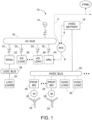
- FIG. 1 is a block diagram depicting in some detail a proposed architecture for a power supply system 10 of a hybrid electric aircraft in accordance with one embodiment.
- the hybrid electric aircraft has four propellers 24 (two on each wing). Only two propellers 24 rotatably mounted to one wing and associated power supply system components are depicted in FIG. 1 .
- the power supply system 10 depicted in FIG. 1 further includes a flight power management controller 12 (hereinafter "FPMC 12"). All of the other components identified in FIG. 1 are associated with one wing of the hybrid electric aircraft and form one half of the power supply system 10.
- the other half (not shown in FIG. 1 ) of the power supply system 10 includes duplicate components associated with the other wing.
- the FPMC 12 manages the electrical propulsion power supplied to both wings.
- each propeller 24 is driven to rotate by a respective electric propulsion motor 26.
- each electric propulsion motor 26 drives multiple propellers.
- Each electric propulsion motor 26 operates under the control of a respective propulsion motor controller 28, which receives aircraft propulsion power from an HVDC bus 20.
- the FPMC 12 is a computer configured (e.g., by software) to manage the HVDC power supplied to the propulsion motor controllers 28.
- the portion of the power supply system 10 depicted in FIG. 1 further includes two AC generators 14 and two HVDC batteries 18.
- Each AC generator 14 is mechanically driven by an internal combustion engine or a gas turbine engine (not shown in FIG. 1 ). Only one AC generator 14 and one HVDC battery 18 (associated with one wing of the hybrid electric aircraft) are shown in FIG. 1 .
- the term “battery” includes least one battery cell inside a battery case and at least one sensor located inside or outside the battery case.
- the battery includes a temperature sensor, a current sensor and a voltage sensor.
- the term “measuring the battery current” means receiving an output of the current sensor and converting the current sensor output to a measurement value.
- the terminals (not shown in the drawings) of the HVDC battery 18 are directly electrically connected by electrical wiring to the HVDC bus 20.
- the terminals of the AC generator 14 are electrically connected by electrical wiring to an AC bus 16 via a contactor 2a.
- the term "contactor” means an electrically controlled switch. Typically the contactor is controlled by a circuit which has a lower power level than the switched circuit.
- a typical contactor comprises contacts and an electromagnet contained in a housing. The contacts are the current-carrying parts of the contactor. The electromagnet provides the driving force to close the contacts. A spring may be provided to return the electromagnet core to its open position relative to the electromagnet coil.
- the housing is an enclosure made of an electrically insulating material.
- the portion of the power supply system 10 depicted in FIG. 1 further includes an active rectifier unit 40 having input terminals that are electrically connected by electrical wiring to the AC bus 16 via a contactor 2b.
- the output terminals of the active rectifier unit 40 are also electrically connected by electrical wiring to the HVDC bus 20.
- the active rectifier unit 40 is controlled to operate in a manner that incoming AC power received from the AC bus 16 is converted to outgoing HVDC power supplied to the HVDC bus 20.
- the propulsion motor controllers 28 and multiple other non-propulsive HVDC loads 30 receive HVDC power from the HVDC bus 20.
- the portion of the power supply system 10 depicted in FIG. 1 further includes a regulated transformer rectifier unit (RTRU) 32 having input terminals that are electrically connected by electrical wiring to the AC bus 16 via a contactor 2c.
- the system also includes a low-voltage direct-current (LVDC) bus 34 that receives regulated AC power from the regulated transformer rectifier unit 32.
- LVDC low-voltage direct-current
- other non-propulsive AC loads 38 receive AC power from the AC bus 16 via respective contactors 2d and connecting electrical wiring.
- the portion of the power supply system 10 depicted in FIG. 1 further includes an active voltage controller 22 that is configured to receive (wirelessly or via wires) sensor data 6 representing the state of the from the HVDC battery 18 and then send (wirelessly or via wires) a control signal 8 representing a magnitude of an HVDC bus reference voltage to the active rectifier unit 40.
- the active rectifier unit 40 in turn controls the voltage of the HVDC bus 20 to match the HVDC bus reference voltage. If the HVDC bus voltage is greater than the voltage of the HVDC battery 18 (hereinafter "battery voltage"), the HVDC battery 18 charges.
- the charge rate is proportional to the magnitude of the difference between the HVDC bus reference voltage and the battery voltage.
- the active voltage controller 22 effectively controls the charge or discharge rate of the HVDC battery 18 by adjusting the HVDC bus reference voltage supplied to the active rectifier unit 40.
- the active voltage controller 22 is configured to receive different mission requests (some of which are described below) from the FPMC 12.
- the term "mission request” means information carried by a control signal sent (wirelessly or via wiring) from the FPMC 12 to the active voltage controller 22 (as indicated by a dashed arrow 4 in FIG. 1 ), which information identifies a change in the HVDC bus voltage to be executed by the active rectifier unit 40.
- the electric generator 14 is a wound rotor generator controlled by a generator controller unit (not shown in FIG. 1 ).
- the wound rotor generator voltage magnitude is controlled by the generator controller unit varying excitation in the rotor field winding.
- the frequency of the AC bus voltage cannot be controlled. Because of that, AC loads have a motor controller or a power converter at their front end to adjust to the varying nature of the AC bus power.
- the power converter that converts AC bus power to HVDC bus power is the active rectifier unit 40.
- the active rectifier unit 40 independently controls the HVDC bus voltage. Because the HVDC battery 18 is directly connected to the HVDC bus 20, the active voltage controller 22 is provided to control the battery charge or discharge rate and for other high-level control techniques to optimize energy usage on the hybrid electric aircraft.
- the generator 14 is a permanent magnet generator (not shown in FIG. 1 ).
- a permanent magnet generator is a generator wherein the excitation field is provided by a rotating permanent magnet instead of a coil.
- the permanent magnet generator voltage which cannot be controlled, changes depending on the speed of the prime mover and generator loading. Therefore, the AC bus voltage will be variable frequency, variable magnitude voltage. Because of that, AC loads will also require a motor controller or a power converter at the front end, similar to the previous case where the generator is a wound rotor generator with a generator controller unit.
- active voltage control is provided for the power converter that converts AC bus power to HVDC bus power because the battery charge and discharge rates need to be controlled.
- the HVDC bus active voltage controller provides extra benefits of enabling the energy optimization control. [As used herein, the term "HVDC bus active voltage controller" refers to the active voltage controller 22 and the active rectifier unit 40 in combination.]
- the active rectifier unit 40 is a solid state power converter that is configured to control the HVDC bus voltage using a PWM control technique. There are many topologies for active rectifiers including boost, buck, Vienna and others.
- the active rectifier unit 40 in turn is controlled by the active voltage controller 22 to enable controlling the charge and discharge rates of the HVDC battery 18 and enable energy use optimization on the hybrid electric aircraft.
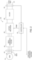
- FIG. 2 is a block diagram identifying some components of the solid-state active rectifier unit 40 included in the architecture depicted in FIG. 1 .
- the active rectifier unit 40 includes an active rectifier 46 controlled by an active rectifier controller 52.
- the active rectifier unit 40 further includes electromagnetic interference (EMI) and harmonics filters 44 (hereinafter “EMI and harmonics filters 44") disposed between the active rectifier 46 and the electric generator 14 and a filter 48 disposed between the active rectifier 46 and the HVDC bus 20 (not shown in FIG. 2 ).
- EMI and harmonics filters 44 electromagnetic interference
- the active rectifier unit 40 includes voltage and current sensing circuits 42 disposed between the electric generator 14 and the EMI and harmonics filters 44 as well as voltage and current sensing circuits 50 disposed between the filter 48 and the HVDC bus 20.
- the active rectifier controller 52 is configured to execute control algorithms that control the states of the switches incorporated in the active rectifier 46.
- the typical control algorithms for the active rectifier unit 40 include power factor correction (PFC) control for meeting AC bus power quality requirements and HVDC bus control for HVDC bus voltage regulation and HVDC bus current limitation and fault protection.
- PFC power factor correction
- HVDC bus control for HVDC bus voltage regulation and HVDC bus current limitation and fault protection.
- the voltage and current sensing circuits 42 sense the voltage V ac and current I ac at the AC side of the active rectifier 46. The outputs of the voltage and current sensing circuits 42 are received by the active rectifier controller 52 and used to enable PFC control.
- the voltage and current sensing circuits 50 sense the voltage V dc and current I dc at the DC side of the active rectifier 46 are received by the active rectifier controller 52 and used to enable HVDC bus voltage regulation and current limitation and fault protection.
- the EMI and harmonics filters 44 and 48 e.g., low-pass filters, each filter comprising an inductor and a capacitor
- the active rectifier 46 consists of a switch network that is controlled using PWM to reduce the DC component of voltage.
- Pulse width modulation is a modulation technique that can be used to control the power supplied to electrical devices.
- the average value of voltage (and current) fed to the load is controlled by turning the switch between supply and load on and off at a fast rate. The longer the switch is on compared to the off periods, the higher the total power supplied to the load.
- the term "duty cycle" describes the proportion of ON time to the regular interval or "period” of time; a low duty cycle corresponds to low power, because the power is off for most of the time.
- the main advantage of PWM is that power loss in the switching devices is very low. When a switch is off there is practically no current, and when it is on and power is being transferred to the load, there is almost no voltage drop across the switch. Power loss, being the product of voltage and current, is thus in both cases close to zero.
- an extra outer feedback loop is provided to enable control of the HVDC battery charge and discharge rates. Additional control loops managing power flow between the battery and the generator source are also possible. Power flow management can be used to optimize energy use efficiency depending on various conditions such as battery SOC, remaining hydrocarbon fuel for the generator prime mover, flight phase, aircraft mission, etc.
- One example control diagram for the active voltage controller 22 that allows for battery charge and discharge rate control and for power flow management is shown on FIG. 3 .
- the output of the active voltage controller 22 to the active rectifier unit 40 is an HVDC bus reference voltage which is either greater or less than the battery voltage.
- the active voltage controller 22 calculates a new HVDC bus reference voltage (whether it needs to be decreases or increased) and communicates new HVDC bus reference voltage to the active rectifier unit 40. More specifically, the active voltage controller 22 includes a current sensor that measures the battery current (hereinafter "measured battery current"). The active voltage controller 22 then controls the HVDC bus voltage by setting and sending a HVDC bus reference voltage to the active rectifier unit 40, which HVDC bus reference voltage is a function of the measured battery current.
- FIG. 3 is a flowchart identifying steps of a control algorithm 100 performed by the active voltage controller 22 in accordance with one proposed implementation.
- the active voltage controller 22 determines the HVDC bus reference voltage in blocks "Increase HVDC bus voltage" (step 106) and "Decrease HVDC bus voltage” (step 110) shown in FIG. 3 .
- the outcome of execution of steps 106 and 110 by the active rectifier unit 40 will be a new HVDC bus reference voltage.
- the active voltage controller 22 measures the HVDC battery current (step 102). Then the active voltage controller 22 determines whether the battery current is greater than the maximum discharge rate or not (step 104). If a determination is made in step 104 that the battery current is discharging at a discharge rate greater than the maximum discharge rate, then the active voltage controller 22 increases the HVDC bus reference voltage and communicates that value to the active rectifier unit 40 by sending a control signal representing a magnitude of the new HVDC bus reference voltage. The active rectifier unit 40 responds to that control signal by increasing the HVDC bus voltage (step 106), thereby reducing the battery discharge rate.
- step 104 determines whether the current into the battery is greater than the maximum discharge rate or not (step 108). If a determination is made in step 108 that the battery current is charging at a charge rate greater than the maximum charge rate, then the active voltage controller 22 decreases the HVDC bus reference voltage and communicates that value to the active rectifier unit 40 by sending a control signal representing a magnitude of the new HVDC bus reference voltage. The active rectifier unit 40 responds to that control signal by decreasing the HVDC bus voltage (step 110), thereby reducing the battery charge rate. If a determination is made in step 108 that the current into the battery is not greater than the maximum charge rate, then the active voltage controller 22 next determines whether the battery state of charge (SOC) is less than the minimum SOC reserve or not (step 112).
- SOC battery state of charge
- SOC State of charge
- the active voltage controller 22 may be configured to calculate the SOC by integrating the battery current over time.
- step 112 determines whether a mission request to increase the power drawn from the battery has been received or not (step 114). If a determination is made in step 114 that a mission request to increase the power drawn from the battery has not been received, then the active voltage controller 22 returns to step 102. If a determination is made in step 114 that a mission request to increase the power drawn from the battery has been received, then the active voltage controller 22 decreases the HVDC bus reference voltage and communicates that value to the active rectifier unit 40 by sending a control signal representing a magnitude of the new HVDC bus reference voltage. The active rectifier unit 40 responds to that control signal by decreasing the HVDC bus voltage (step 110), thereby increasing the discharge rate of the battery (step 116). The active voltage controller 22 then returns to step 102.
- step 112 determines whether the battery SOC is less than the minimum SOC reserve. If a determination is made in step 112 that the battery SOC is less than the minimum SOC reserve, then the active voltage controller 22 determines whether the fuel reserve is less than the minimum fuel reserve or not (step 118). If a determination is made in step 118 that the fuel reserve is less than the minimum fuel reserve, then the active voltage controller 22 sends a message to the pilots to initiate descent (step 120). If a determination is made in step 118 that the fuel reserve is not less than the minimum fuel reserve, then the active voltage controller 22 performs steps 122 and 126.
- step 122 the active voltage controller 22 determines whether the whether a mission request to increase the power drawn from the generator has been received or not. If a determination is made in step 122 that a mission request to increase the power drawn from the generator has not been received, then the active voltage controller 22 returns to step 102. If a determination is made in step 122 that a mission request to increase the power drawn from the generator has been received, then the active voltage controller 22 increases the HVDC bus reference voltage and communicates that value to the active rectifier unit 40 by sending a control signal representing a magnitude of the new HVDC bus reference voltage. The active rectifier unit 40 responds to that control signal by increasing the HVDC bus voltage (step 124), thereby reducing the battery discharge rate. (As used herein, the terms “decrease” and “reduce” are interchangeable synonyms.) The active voltage controller 22 then returns to step 102.
- step 126 the active voltage controller 22 determines whether the whether a mission request to charge the battery has been received or not. If a determination is made in step 126 that a mission request to charge the battery has not been received, then the active voltage controller 22 returns to step 102. If a determination is made in step 126 that a mission request to charge the battery has been received, then the active voltage controller 22 increases the HVDC bus reference voltage and communicates that value to the active rectifier unit 40 by sending a control signal representing a magnitude of the new HVDC bus reference voltage. The active rectifier unit 40 responds to that control signal by increasing the HVDC bus voltage to a level greater than the battery voltage (step 128), thereby first reducing the discharge rate and then increasing the charge rate of the battery. The active voltage controller 22 then returns to step 102.
- the active voltage controller 22 also receives commands from the aircraft flight power management controller 12 (hereinafter "FPMC 12").
- the FPMC 12 is a computer configured (e.g., by software) to direct the active voltage controller 22 to draw more power from HVDC battery 18 or from the electric generator 14 or to charge the HVDC battery 18.
- the FPMC 12 also receives information from the active voltage controller 22 on status of the HVDC battery 18, such as current battery SOC and current charging or discharging rate. Based on mission profile, aircraft status, phase of flight, etc., the FPMC 12 is configured to make decisions on how to manage power flow in the system.
- Aircraft missions vary from one flight to another. Some flights are short range and some have longer ranges. Aircraft weight also could change from one flight to another, which weight change affects the range of the aircraft. For very short flights and/or lighter loads, it would be advantageous to use more battery power to reduce fuel consumption. Typically the battery or batteries onboard the aircraft are recharged on the ground. Conversely, for longer flights and heavier loads, more hydrocarbon fuel could be used, while the battery provides assistance during some flight phases. During descent, if electric propulsion motors are used to decelerate an aircraft, the resulting regenerative power could be used to charge the battery.
- the function of the FPMC 12 is to perform power flow management in a hybrid electric aircraft to optimize overall energy usage and reduce fuel burn during a particular mission.
- FIG. 4 is a flowchart identifying steps of a control algorithm 140 performed by the FPMC 12 in accordance with one proposed implementation.
- the FPMC 12 is configured to make a determination whether the aircraft is on the ground or not (step 142). On the one hand, if a determination is made in step 142 that the aircraft is on the ground, then the FPMC 12 determines whether the battery is discharged or not (step 144). On the other hand, if a determination is made in step 142 that the aircraft is not on the ground, then the FPMC 12 determines what the current phase of the flight of the aircraft is (step 162).
- the FPMC 12 determines in step 154 whether a mission profile has been input by the crew or not. On the one hand, if a determination is made in step 154 that a mission profile has not been input by the crew, the FPMC 12 loads a default battery usage profile (step 156).
- the default battery usage profile can be established by the typical airplane mission (short- or long-range mission), weight of the aircraft or number of people and amount of cargo on board, and optimization with respect to fuel burn reduction.
- the FPMC 12 determines the battery SOC and the fuel level (step 158). Then the FPMC 12 loads an optimum fuel usage battery profile for a mission (step 160).
- the optimum fuel usage battery profile is configured so that the battery is utilized to minimize conventional fuel burn and maximize battery usage. Depending on battery SOC and remaining electrical energy in the battery, weight of the airplane and airplane mission, the optimum fuel usage battery profile will minimize fuel burn by maximizing use of the battery power throughout the flight cycle. The optimum fuel usage battery profile will also ensure that the battery is not over-discharged at the end of flight cycle and that the battery discharge rate does not exceed maximum allowable discharge rate during flight.
- the default battery usage profile may be different than the optimum fuel usage battery profile. For example, the default battery usage profile may not be optimal from the fuel burn standpoint, but may be optimal from the standpoint of speed or other mission parameter.
- step 144 is performed following a determination by the FPMC 12 that the aircraft is on the ground. On the one hand, if a determination is made in step 144 that the battery is not discharged, then the FPMC 12 returns to step 142. On the other hand, if a determination is made in step 144 that the battery is discharged, then the FPMC 12 determines whether any one of a plurality of power sources (e.g., external power, auxiliary power unit or engine power) is available or not (step 146). On the one hand, if a determination is made in step 146 that a power source is not available, then the FPMC 12 returns to step 142.
- a plurality of power sources e.g., external power, auxiliary power unit or engine power
- step 146 determines how much power can be used for charging the HVDC battery 18. After determining how much power can be used for battery charging, the FPMC 12 sets the battery charging current (step 150) and then commands the active voltage controller 22 to charge the battery using the set battery charging current (step 152).
- step 162 is performed following a determination by the FPMC 12 that the aircraft is not on the ground.
- the FPMC 12 next determines the battery SOC and the fuel level (step 164). Then the FPMC 12 adjusts the battery usage profile in dependence on the flight phase, battery SOC and fuel level (step 166). After adjusting the battery usage profile, the FPMC 12 sets the battery discharging or charging current in accordance with the adjusted battery usage profile (step 168) and then commands the active voltage controller 22 to discharge or charge the battery using the set battery discharging or charging current.
Landscapes
- Engineering & Computer Science (AREA)
- Power Engineering (AREA)
- Mechanical Engineering (AREA)
- Transportation (AREA)
- Life Sciences & Earth Sciences (AREA)
- Sustainable Development (AREA)
- Sustainable Energy (AREA)
- Charge And Discharge Circuits For Batteries Or The Like (AREA)
- Direct Current Feeding And Distribution (AREA)
- Control Of Eletrric Generators (AREA)
Claims (15)
- Ein hybrides elektrisches Stromversorgungssystem (10) für ein Flugzeug zur Stromversorgung einer Last, wobei das hybride elektrische Stromversorgungssystem Folgendes aufweist:eine Wechselstromquelle, wobei die Wechselstromquelle einen elektrischen Generator (14) aufweist;einen AC-Bus (16);eine erste Schalteinrichtung, die so angeordnet ist, dass sie Wechselstrom von der Wechselstromquelle schaltbar mit dem Wechselstrombus koppelt;eine HVDC-Stromquelle, wobei die HVDC-Stromquelle eine Batterie aufweist;einen aktiven Spannungsregler (22), der so konfiguriert ist, dass er ein Steuersignal erzeugt, das eine Größe einer HVDC-Bus-Referenzspannung darstellt;eine aktive Gleichrichtereinheit (40), die einen aktiven Gleichrichter (46) aufweist, der so konfiguriert ist, dass er Wechselstrom in HV(High Voltage)-Gleichstrom umwandelt, und einen Controller (52), der so konfiguriert ist, dass er den aktiven Gleichrichter steuert, um eine HVDC-Busspannung in Abhängigkeit von dem vom aktiven Spannungscontroller empfangenen Steuersignal einzustellen;eine zweite Schalteinrichtung, die so angeordnet ist, dass sie Wechselstrom vom Wechselstrombus schaltbar an die aktive Gleichrichtereinheit koppelt;einen HVDC-Bus, der so gekoppelt ist, dass er Gleichstrom von der HVDC-Stromquelle und/oder der aktiven Gleichrichtereinheit in Abhängigkeit von der HVDC-Busspannung von der aktiven Gleichrichtereinheit empfängt;eine HVDC-Last (30), die so gekoppelt ist, dass sie HVDC-Strom vom HVDC-Bus empfängt; undeinen Flugleistungsmanagementregler (12), der so konfiguriert ist, dass er Leistungsflussmanagementbefehle an den aktiven Spannungsregler sendet, um den Gesamtstromverbrauch zu optimieren und den Treibstoffverbrauch zu reduzieren, wobei der Flugleistungsmanagementregler so konfiguriert ist, dass er Vorgänge aufweist:Bestimmen der aktuellen Flugphase des Flugzeugs;Bestimmen des Ladezustands einer Batterie (18);Bestimmen des Kraftstoffstandes;Anpassen eines Batterienutzungsprofils in Abhängigkeit von der Flugphase, dem Ladezustand der Batterie und dem Kraftstoffstand;Einstellen eines Batterieentlade- oder -ladestroms in Übereinstimmung mit dem eingestellten Batterienutzungsprofil; undAnweisen des aktiven Spannungsregler, um die Batterie entsprechend dem eingestellten Batterie-Entlade- oder Ladestrom zu entladen oder zu laden.
- Das hybride elektrische Stromversorgungssystem nach Anspruch 1, wobei die HVDC-Last einen Motorregler aufweist, der so gekoppelt ist, dass er HVDC-Leistung vom HVDC-Bus empfängt.
- Das hybride elektrische Stromversorgungssystem nach einem der Ansprüche 1 bis 2, das ferner eine Wechselstromlast und eine dritte Schalteinrichtung aufweist, die so angeordnet ist, dass sie Wechselstrom vom Wechselstrombus an die Wechselstromlast schaltbar koppelt.
- Das hybride elektrische Stromversorgungssystem nach einem der Ansprüche 1 bis 3, wobei:der aktive Spannungsregler einen Computer oder Prozessor aufweist, der so programmiert ist, dass er das Steuersignal in verschiedenen Formen erzeugt, die verschiedenen Größen der HVDC-Bus-Referenzspannung entsprechen; undder Controller der aktiven Gleichrichtereinheit so konfiguriert ist, dass er den aktiven Gleichrichter steuert, um die HVDC-Busspannung des HVDC-Busses in Abhängigkeit von der Größe der HVDC-Bus-Referenzspannung anzupassen.
- Das hybride elektrische Stromversorgungssystem nach einem der Ansprüche 1 bis 4, wobei der elektrische Generator (14) von einem Gasturbinenmotor oder einem Verbrennungsmotor angetrieben wird.
- Das hybride elektrische Stromversorgungssystem nach Anspruch 1, wobei das Steuersignal ein Befehl ist, die HVDC-Busspannung zu erhöhen, wenn der Strom aus der Batterie größer ist als eine maximale Entladungsrate.
- Das hybride elektrische Stromversorgungssystem nach Anspruch 1, wobei das Steuersignal ein Befehl zur Verringerung der HVDC-Busspannung ist, wenn der in die Batterie fließende Strom größer als eine maximale Laderate ist.
- Das hybride elektrische Stromversorgungssystem nach Anspruch 1, wobei der aktive Spannungsregler eine Nachricht zur Einleitung des Abstiegs erzeugt, wenn sowohl eine erste als auch eine zweite Bedingung erfüllt sind, wobei die erste Bedingung darin besteht, dass ein Ladezustand der Batterie geringer ist als eine minimale Ladezustandsreserve, und die zweite Bedingung darin, dass eine Kraftstoffreserve geringer ist als eine minimale Kraftstoffreserve.
- Das hybride elektrische Stromversorgungssystem nach einem der vorhergehenden Ansprüche, wobei der Flugleistungsmanagement-Controller ferner so konfiguriert ist, dass er einen Befehl an den aktiven Spannungscontroller sendet, um die Batterie zu laden, wenn sich das Flugzeug am Boden befindet, die Batterie entladen ist und eine Stromquelle verfügbar ist.
- Das hybride elektrische Stromversorgungssystem nach einem der vorhergehenden Ansprüche, wobei die aktive Gleichrichtereinheit so konfiguriert ist, dass sie die HVDC-Busspannung unter Verwendung einer pulsweitenmodulierten "PWM"-Regelungstechnik regelt.
- Das hybride elektrische Stromversorgungssystem nach einem der vorhergehenden Ansprüche, wobei die aktive Gleichrichtereinheit Hochleistungs-Halbleiterschalter mit hoher Frequenz und schnellen Abschaltfähigkeiten enthält.
- Das hybride elektrische Stromversorgungssystem nach Anspruch 1, wobei der elektrische Generator ein gewickelter Rotorgenerator ist, der von einer Generatorsteuereinheit gesteuert wird.
- Das hybride elektrische Stromversorgungssystem nach Anspruch 1, wobei der elektrische Generator ein Permanentmagnetgenerator ist.
- Flugzeug, das die hybride elektrische Stromversorgung nach einem der vorhergehenden Ansprüche aufweist, wobei der aktive Spannungsregler so konfiguriert ist, dass er das Steuersignal, das die Größe der HVDC-Bus-Referenzspannung darstellt, auf der Grundlage eines Stroms der HVDC-Stromquelle erzeugt, wobei das Flugzeug Folgendes aufweist:einen elektrischen Antriebsmotor (26), der so gekoppelt ist,dass er HVDC-Strom vom HVDC-Bus empfängt; undeinen Propeller (24), der betriebsmäßig mit dem elektrischen Antriebsmotor gekoppelt ist.
- Das Flugzeug nach Anspruch 14, wobei das Flugzeug vier Propeller hat, zwei an jedem Flügel.
Applications Claiming Priority (1)
| Application Number | Priority Date | Filing Date | Title |
|---|---|---|---|
| US16/289,900 US10589635B1 (en) | 2019-03-01 | 2019-03-01 | Active voltage control for hybrid electric aircraft |
Publications (2)
| Publication Number | Publication Date |
|---|---|
| EP3703220A1 EP3703220A1 (de) | 2020-09-02 |
| EP3703220B1 true EP3703220B1 (de) | 2024-01-24 |
Family
ID=69630166
Family Applications (1)
| Application Number | Title | Priority Date | Filing Date |
|---|---|---|---|
| EP20157446.4A Active EP3703220B1 (de) | 2019-03-01 | 2020-02-14 | Aktive spannungsregelung für hybrides elektroflugzeug |
Country Status (4)
| Country | Link |
|---|---|
| US (1) | US10589635B1 (de) |
| EP (1) | EP3703220B1 (de) |
| JP (1) | JP7492340B2 (de) |
| CN (1) | CN111641250B (de) |
Families Citing this family (35)
| Publication number | Priority date | Publication date | Assignee | Title |
|---|---|---|---|---|
| US11214378B2 (en) | 2018-08-21 | 2022-01-04 | Zunum Aero, Inc. | System controller for series hybrid powertrain |
| US11312503B1 (en) | 2018-12-17 | 2022-04-26 | Zunum Aero, Inc. | Systems and methods for implementing lightweight and reliable hybrid or electric powertrains for aircraft |
| US11035300B2 (en) * | 2019-03-29 | 2021-06-15 | Rolls-Royce Corporation | Control of a gas turbine driving a generator of an electrical system based on faults detected in the electrical system |
| FR3095090B1 (fr) * | 2019-04-11 | 2023-11-03 | Safran | Procédé et dispositif de contrôle de l’hybridation d’un aéronef |
| US11128251B1 (en) | 2020-04-29 | 2021-09-21 | The Boeing Company | Fault-tolerant power system architecture for aircraft electric propulsion |
| US11738875B2 (en) * | 2020-12-11 | 2023-08-29 | Launch Point Electric Propulsion Solutions, Inc. | Lightweight, high-efficiency, energy-dense, hybrid power system for reliable electric flight |
| FR3118622B1 (fr) * | 2021-01-06 | 2022-12-09 | Ascendance Flight Tech | Aéronef à source d’énergie hybride |
| US12348063B2 (en) | 2021-02-11 | 2025-07-01 | The Boeing Company | Systems and methods for fail-safe battery protection independent from battery management system |
| JP7542461B2 (ja) * | 2021-03-09 | 2024-08-30 | 本田技研工業株式会社 | 航空機用推進システム |
| US11952105B2 (en) | 2021-03-10 | 2024-04-09 | BETA Technologies, Inc. | System and method for flight control in electric aircraft |
| US12434814B2 (en) | 2021-03-10 | 2025-10-07 | Beta Air Llc | System and methods for flight control for an electric aircraft |
| US11958590B2 (en) | 2021-03-10 | 2024-04-16 | Beta Air, Llc | System and a method for a battery power management system for an electric aircraft |
| KR102394340B1 (ko) * | 2021-08-27 | 2022-05-06 | 아이케이세미콘주식회사 | 차량용 레귤레이터 장치 |
| US11577848B1 (en) | 2021-10-30 | 2023-02-14 | Beta Air, Llc | Systems and methods for estimating flight range of an electric aircraft |
| WO2023091579A1 (en) * | 2021-11-17 | 2023-05-25 | Verdego Aero, Inc. | Split turbocharger having independent electric turbine and electric compressor components |
| US11562653B1 (en) * | 2021-11-17 | 2023-01-24 | Beta Air, Llc | Systems and methods for in-flight re-routing of an electric aircraft |
| FR3131072B1 (fr) * | 2021-12-22 | 2023-12-15 | Safran Electrical & Power | Dispositif de coupure électrique à contact auxiliaire |
| JP7580368B2 (ja) | 2021-12-24 | 2024-11-11 | 本田技研工業株式会社 | 飛行体の制御装置 |
| FR3132600B1 (fr) | 2022-02-07 | 2024-01-12 | Safran Electrical & Power | Unité de commande de la puissance d’une batterie, aéronef comprenant ladite unité de commande et procédé de commande correspondant. |
| FR3132696B1 (fr) | 2022-02-14 | 2024-06-21 | Safran Electrical & Power | Dispositif de distribution de puissance électrique en tension continue, système de propulsion et aéronef associés |
| EP4245666B1 (de) * | 2022-03-18 | 2025-06-25 | Illinois Tool Works Inc. | Bodenstützausrüstung |
| JP7744282B2 (ja) * | 2022-03-30 | 2025-09-25 | 本田技研工業株式会社 | 航空機の制御装置 |
| US11936286B2 (en) | 2022-05-10 | 2024-03-19 | Hamilton Sundstrand Corporation | Systems and methods for power generation control |
| EP4328067A1 (de) * | 2022-08-25 | 2024-02-28 | Honeywell International Inc. | Energieverwaltung von hybriden elektrischen systemen |
| US12328028B2 (en) | 2022-08-25 | 2025-06-10 | Honeywell International Inc. | Energy management of hybrid electrical systems |
| CN115716415A (zh) * | 2022-11-15 | 2023-02-28 | 中国航发湖南动力机械研究所 | 一种串联式混合动力供给系统及方法 |
| US12311800B2 (en) * | 2022-12-21 | 2025-05-27 | Rockwell Collins, Inc. | System and method for performance prediction of electric aircraft |
| EP4395106A1 (de) * | 2022-12-29 | 2024-07-03 | Airbus Operations, S.L.U. | Adaptive batterieladung |
| US20240250543A1 (en) * | 2023-01-23 | 2024-07-25 | Northrop Grumman Systems Corporation | Quasi-load following (q-lf) high efficiency fault tolerant hybrid electric power system control method |
| EP4432532A1 (de) | 2023-03-13 | 2024-09-18 | Goodrich Control Systems | Gewichteter sollwert für aktive gleichrichterstabilität |
| IT202300006897A1 (it) * | 2023-04-07 | 2024-10-07 | Hitecs S R L | Velivolo senza pilota ad alimentazione ibrida |
| EP4721220A1 (de) * | 2023-06-02 | 2026-04-08 | Joule Case Inc. | Weitbereichsstrom- und verschachtelte energieübertragung (wassernetz) |
| SE547061C2 (en) * | 2023-07-07 | 2025-04-15 | Heart Aerospace AB | An energy distribution system for an aircraft |
| EP4496162A1 (de) * | 2023-07-19 | 2025-01-22 | APUS Zero Emission GmbH | Elektrisches energiesystem, verfahren und computerprogrammprodukt für ein flugzeug |
| KR102918144B1 (ko) * | 2025-11-10 | 2026-01-26 | 국방과학연구소 | 컨택터 기반 비행체 전력 분배 시스템 및 이의 제어 방법 |
Family Cites Families (21)
| Publication number | Priority date | Publication date | Assignee | Title |
|---|---|---|---|---|
| CA1313219C (en) | 1988-10-07 | 1993-01-26 | Boon-Teck Ooi | Pulse width modulation high voltage direct current transmission system and converter |
| US5587647A (en) * | 1995-06-30 | 1996-12-24 | Sundstrand Corporation | Dual output synchronous-induction starting/generating system |
| FR2909233B1 (fr) * | 2006-11-23 | 2011-03-04 | Hispano Suiza Sa | Alimentation d'un aeronef en energie electrique |
| US20090195074A1 (en) * | 2008-01-31 | 2009-08-06 | Buiel Edward R | Power supply and storage device for improving drilling rig operating efficiency |
| ATE480033T1 (de) | 2008-02-27 | 2010-09-15 | Abb Schweiz Ag | Energiesystem umfassend eine wind- oder wasserkraftturbine |
| US8128019B2 (en) * | 2008-12-12 | 2012-03-06 | Honeywell International Inc. | Hybrid power for ducted fan unmanned aerial systems |
| US8296036B2 (en) * | 2009-09-23 | 2012-10-23 | Aerovironment, Inc. | Aircraft power management |
| US8552588B2 (en) * | 2009-11-05 | 2013-10-08 | Tai-Her Yang | Battery charging coaction and output system with current limit supply |
| US8314588B2 (en) * | 2009-11-18 | 2012-11-20 | Honeywell International Inc. | Control system for battery charge maintenance in a power system with main AC generator control |
| JP5550954B2 (ja) * | 2010-03-15 | 2014-07-16 | 住友重機械工業株式会社 | ハイブリッド型作業機械 |
| US8738268B2 (en) * | 2011-03-10 | 2014-05-27 | The Boeing Company | Vehicle electrical power management and distribution |
| US9008879B2 (en) * | 2012-07-05 | 2015-04-14 | General Electric Company | System and method for operating a hybrid vehicle system |
| US20140197681A1 (en) * | 2012-07-30 | 2014-07-17 | The Boeing Company | Electric system stabilizing system for aircraft |
| US11267574B2 (en) | 2013-10-28 | 2022-03-08 | The Boeing Company | Aircraft with electric motor and rechargeable power source |
| CA2975827A1 (en) * | 2015-02-18 | 2016-08-25 | Ge Aviation Systems Llc | Aircraft starting and generating system |
| FR3038796B1 (fr) * | 2015-07-09 | 2017-08-11 | Moteurs Leroy-Somer | Systeme de generation d'energie a traitement ameliore des impacts a charge, des delestages et des harmoniques |
| JP2017056747A (ja) * | 2015-09-14 | 2017-03-23 | 三菱電機株式会社 | 表示制御装置、表示装置および音像位置制御方法 |
| JP6169203B1 (ja) * | 2016-02-16 | 2017-07-26 | 三菱電機株式会社 | 電動機制御装置および電動機制御方法 |
| CN105680525B (zh) * | 2016-04-06 | 2018-11-30 | 国网电力科学研究院武汉南瑞有限责任公司 | 一种基于混合母线的充电车供电系统及其控制方法 |
| GB201615900D0 (en) * | 2016-09-19 | 2016-11-02 | Rolls Royce Plc | Aircraft propulsion system |
| CN108736481A (zh) * | 2018-05-03 | 2018-11-02 | 南京航空航天大学 | 一种航空多电发动机交直流混合电力系统及其设计方法 |
-
2019
- 2019-03-01 US US16/289,900 patent/US10589635B1/en active Active
-
2020
- 2020-02-14 EP EP20157446.4A patent/EP3703220B1/de active Active
- 2020-02-14 JP JP2020023168A patent/JP7492340B2/ja active Active
- 2020-02-24 CN CN202010111486.1A patent/CN111641250B/zh active Active
Also Published As
| Publication number | Publication date |
|---|---|
| US10589635B1 (en) | 2020-03-17 |
| CN111641250A (zh) | 2020-09-08 |
| JP7492340B2 (ja) | 2024-05-29 |
| CN111641250B (zh) | 2024-07-05 |
| JP2020182372A (ja) | 2020-11-05 |
| EP3703220A1 (de) | 2020-09-02 |
Similar Documents
| Publication | Publication Date | Title |
|---|---|---|
| EP3703220B1 (de) | Aktive spannungsregelung für hybrides elektroflugzeug | |
| US11495982B2 (en) | System and method for allocating propulsion load power drawn from high-energy and high-power batteries | |
| US10396565B2 (en) | System and method for power distribution | |
| EP3367532B1 (de) | Leistungsverwaltungs- und verteilungsarchitektur für ein raumfahrzeug | |
| EP3044846B1 (de) | Energieanlage für ein flugzeug mit dual hybriden leistungsquellen | |
| US10279759B2 (en) | System and method for stabilizing aircraft electrical systems | |
| US20120104861A1 (en) | High voltage electric accumulators with internal distributed dc-dc converters for self regulation and protection | |
| US12252261B2 (en) | Hybrid propulsion unit for an aircraft | |
| CN113748064B (zh) | 用于监控航空器混合的方法和装置 | |
| US11554875B2 (en) | Method of electrically powering an electricity network, and an electrical architecture | |
| EP4708606A1 (de) | Gleichstrom-gleichstrom-parallelisierungssteuerungsalgorithmus | |
| CN115549219A (zh) | 混合供电系统、多电飞机混合供电架构以及充放电方法 | |
| CN115173392A (zh) | 一种航空用兆瓦级高压大功率供电系统及其控制方法 |
Legal Events
| Date | Code | Title | Description |
|---|---|---|---|
| PUAI | Public reference made under article 153(3) epc to a published international application that has entered the european phase |
Free format text: ORIGINAL CODE: 0009012 |
|
| STAA | Information on the status of an ep patent application or granted ep patent |
Free format text: STATUS: THE APPLICATION HAS BEEN PUBLISHED |
|
| AK | Designated contracting states |
Kind code of ref document: A1 Designated state(s): AL AT BE BG CH CY CZ DE DK EE ES FI FR GB GR HR HU IE IS IT LI LT LU LV MC MK MT NL NO PL PT RO RS SE SI SK SM TR |
|
| AX | Request for extension of the european patent |
Extension state: BA ME |
|
| STAA | Information on the status of an ep patent application or granted ep patent |
Free format text: STATUS: REQUEST FOR EXAMINATION WAS MADE |
|
| 17P | Request for examination filed |
Effective date: 20210225 |
|
| RBV | Designated contracting states (corrected) |
Designated state(s): AL AT BE BG CH CY CZ DE DK EE ES FI FR GB GR HR HU IE IS IT LI LT LU LV MC MK MT NL NO PL PT RO RS SE SI SK SM TR |
|
| STAA | Information on the status of an ep patent application or granted ep patent |
Free format text: STATUS: EXAMINATION IS IN PROGRESS |
|
| 17Q | First examination report despatched |
Effective date: 20210803 |
|
| GRAP | Despatch of communication of intention to grant a patent |
Free format text: ORIGINAL CODE: EPIDOSNIGR1 |
|
| STAA | Information on the status of an ep patent application or granted ep patent |
Free format text: STATUS: GRANT OF PATENT IS INTENDED |
|
| RAP3 | Party data changed (applicant data changed or rights of an application transferred) |
Owner name: THE BOEING COMPANY |
|
| INTG | Intention to grant announced |
Effective date: 20230322 |
|
| GRAJ | Information related to disapproval of communication of intention to grant by the applicant or resumption of examination proceedings by the epo deleted |
Free format text: ORIGINAL CODE: EPIDOSDIGR1 |
|
| STAA | Information on the status of an ep patent application or granted ep patent |
Free format text: STATUS: EXAMINATION IS IN PROGRESS |
|
| GRAP | Despatch of communication of intention to grant a patent |
Free format text: ORIGINAL CODE: EPIDOSNIGR1 |
|
| STAA | Information on the status of an ep patent application or granted ep patent |
Free format text: STATUS: GRANT OF PATENT IS INTENDED |
|
| INTC | Intention to grant announced (deleted) | ||
| P01 | Opt-out of the competence of the unified patent court (upc) registered |
Effective date: 20230808 |
|
| INTG | Intention to grant announced |
Effective date: 20230824 |
|
| GRAS | Grant fee paid |
Free format text: ORIGINAL CODE: EPIDOSNIGR3 |
|
| GRAA | (expected) grant |
Free format text: ORIGINAL CODE: 0009210 |
|
| STAA | Information on the status of an ep patent application or granted ep patent |
Free format text: STATUS: THE PATENT HAS BEEN GRANTED |
|
| AK | Designated contracting states |
Kind code of ref document: B1 Designated state(s): AL AT BE BG CH CY CZ DE DK EE ES FI FR GB GR HR HU IE IS IT LI LT LU LV MC MK MT NL NO PL PT RO RS SE SI SK SM TR |
|
| REG | Reference to a national code |
Ref country code: GB Ref legal event code: FG4D |
|
| REG | Reference to a national code |
Ref country code: CH Ref legal event code: EP |
|
| REG | Reference to a national code |
Ref country code: IE Ref legal event code: FG4D |
|
| REG | Reference to a national code |
Ref country code: DE Ref legal event code: R096 Ref document number: 602020024676 Country of ref document: DE |
|
| REG | Reference to a national code |
Ref country code: LT Ref legal event code: MG9D |
|
| REG | Reference to a national code |
Ref country code: NL Ref legal event code: MP Effective date: 20240124 |
|
| PG25 | Lapsed in a contracting state [announced via postgrant information from national office to epo] |
Ref country code: NL Free format text: LAPSE BECAUSE OF FAILURE TO SUBMIT A TRANSLATION OF THE DESCRIPTION OR TO PAY THE FEE WITHIN THE PRESCRIBED TIME-LIMIT Effective date: 20240124 |
|
| PG25 | Lapsed in a contracting state [announced via postgrant information from national office to epo] |
Ref country code: NL Free format text: LAPSE BECAUSE OF FAILURE TO SUBMIT A TRANSLATION OF THE DESCRIPTION OR TO PAY THE FEE WITHIN THE PRESCRIBED TIME-LIMIT Effective date: 20240124 |
|
| PG25 | Lapsed in a contracting state [announced via postgrant information from national office to epo] |
Ref country code: IS Free format text: LAPSE BECAUSE OF FAILURE TO SUBMIT A TRANSLATION OF THE DESCRIPTION OR TO PAY THE FEE WITHIN THE PRESCRIBED TIME-LIMIT Effective date: 20240524 |
|
| PG25 | Lapsed in a contracting state [announced via postgrant information from national office to epo] |
Ref country code: LT Free format text: LAPSE BECAUSE OF FAILURE TO SUBMIT A TRANSLATION OF THE DESCRIPTION OR TO PAY THE FEE WITHIN THE PRESCRIBED TIME-LIMIT Effective date: 20240124 |
|
| PG25 | Lapsed in a contracting state [announced via postgrant information from national office to epo] |
Ref country code: GR Free format text: LAPSE BECAUSE OF FAILURE TO SUBMIT A TRANSLATION OF THE DESCRIPTION OR TO PAY THE FEE WITHIN THE PRESCRIBED TIME-LIMIT Effective date: 20240425 |
|
| REG | Reference to a national code |
Ref country code: AT Ref legal event code: MK05 Ref document number: 1652940 Country of ref document: AT Kind code of ref document: T Effective date: 20240124 |
|
| PG25 | Lapsed in a contracting state [announced via postgrant information from national office to epo] |
Ref country code: RS Free format text: LAPSE BECAUSE OF FAILURE TO SUBMIT A TRANSLATION OF THE DESCRIPTION OR TO PAY THE FEE WITHIN THE PRESCRIBED TIME-LIMIT Effective date: 20240424 Ref country code: HR Free format text: LAPSE BECAUSE OF FAILURE TO SUBMIT A TRANSLATION OF THE DESCRIPTION OR TO PAY THE FEE WITHIN THE PRESCRIBED TIME-LIMIT Effective date: 20240124 |
|
| PG25 | Lapsed in a contracting state [announced via postgrant information from national office to epo] |
Ref country code: ES Free format text: LAPSE BECAUSE OF FAILURE TO SUBMIT A TRANSLATION OF THE DESCRIPTION OR TO PAY THE FEE WITHIN THE PRESCRIBED TIME-LIMIT Effective date: 20240124 |
|
| PG25 | Lapsed in a contracting state [announced via postgrant information from national office to epo] |
Ref country code: AT Free format text: LAPSE BECAUSE OF FAILURE TO SUBMIT A TRANSLATION OF THE DESCRIPTION OR TO PAY THE FEE WITHIN THE PRESCRIBED TIME-LIMIT Effective date: 20240124 |
|
| PG25 | Lapsed in a contracting state [announced via postgrant information from national office to epo] |
Ref country code: RS Free format text: LAPSE BECAUSE OF FAILURE TO SUBMIT A TRANSLATION OF THE DESCRIPTION OR TO PAY THE FEE WITHIN THE PRESCRIBED TIME-LIMIT Effective date: 20240424 Ref country code: NO Free format text: LAPSE BECAUSE OF FAILURE TO SUBMIT A TRANSLATION OF THE DESCRIPTION OR TO PAY THE FEE WITHIN THE PRESCRIBED TIME-LIMIT Effective date: 20240424 Ref country code: LT Free format text: LAPSE BECAUSE OF FAILURE TO SUBMIT A TRANSLATION OF THE DESCRIPTION OR TO PAY THE FEE WITHIN THE PRESCRIBED TIME-LIMIT Effective date: 20240124 Ref country code: IS Free format text: LAPSE BECAUSE OF FAILURE TO SUBMIT A TRANSLATION OF THE DESCRIPTION OR TO PAY THE FEE WITHIN THE PRESCRIBED TIME-LIMIT Effective date: 20240524 Ref country code: HR Free format text: LAPSE BECAUSE OF FAILURE TO SUBMIT A TRANSLATION OF THE DESCRIPTION OR TO PAY THE FEE WITHIN THE PRESCRIBED TIME-LIMIT Effective date: 20240124 Ref country code: GR Free format text: LAPSE BECAUSE OF FAILURE TO SUBMIT A TRANSLATION OF THE DESCRIPTION OR TO PAY THE FEE WITHIN THE PRESCRIBED TIME-LIMIT Effective date: 20240425 Ref country code: FI Free format text: LAPSE BECAUSE OF FAILURE TO SUBMIT A TRANSLATION OF THE DESCRIPTION OR TO PAY THE FEE WITHIN THE PRESCRIBED TIME-LIMIT Effective date: 20240124 Ref country code: ES Free format text: LAPSE BECAUSE OF FAILURE TO SUBMIT A TRANSLATION OF THE DESCRIPTION OR TO PAY THE FEE WITHIN THE PRESCRIBED TIME-LIMIT Effective date: 20240124 Ref country code: BG Free format text: LAPSE BECAUSE OF FAILURE TO SUBMIT A TRANSLATION OF THE DESCRIPTION OR TO PAY THE FEE WITHIN THE PRESCRIBED TIME-LIMIT Effective date: 20240124 Ref country code: AT Free format text: LAPSE BECAUSE OF FAILURE TO SUBMIT A TRANSLATION OF THE DESCRIPTION OR TO PAY THE FEE WITHIN THE PRESCRIBED TIME-LIMIT Effective date: 20240124 |
|
| PG25 | Lapsed in a contracting state [announced via postgrant information from national office to epo] |
Ref country code: PT Free format text: LAPSE BECAUSE OF FAILURE TO SUBMIT A TRANSLATION OF THE DESCRIPTION OR TO PAY THE FEE WITHIN THE PRESCRIBED TIME-LIMIT Effective date: 20240524 Ref country code: PL Free format text: LAPSE BECAUSE OF FAILURE TO SUBMIT A TRANSLATION OF THE DESCRIPTION OR TO PAY THE FEE WITHIN THE PRESCRIBED TIME-LIMIT Effective date: 20240124 |
|
| PG25 | Lapsed in a contracting state [announced via postgrant information from national office to epo] |
Ref country code: SE Free format text: LAPSE BECAUSE OF FAILURE TO SUBMIT A TRANSLATION OF THE DESCRIPTION OR TO PAY THE FEE WITHIN THE PRESCRIBED TIME-LIMIT Effective date: 20240124 Ref country code: PT Free format text: LAPSE BECAUSE OF FAILURE TO SUBMIT A TRANSLATION OF THE DESCRIPTION OR TO PAY THE FEE WITHIN THE PRESCRIBED TIME-LIMIT Effective date: 20240524 Ref country code: PL Free format text: LAPSE BECAUSE OF FAILURE TO SUBMIT A TRANSLATION OF THE DESCRIPTION OR TO PAY THE FEE WITHIN THE PRESCRIBED TIME-LIMIT Effective date: 20240124 Ref country code: LV Free format text: LAPSE BECAUSE OF FAILURE TO SUBMIT A TRANSLATION OF THE DESCRIPTION OR TO PAY THE FEE WITHIN THE PRESCRIBED TIME-LIMIT Effective date: 20240124 |
|
| REG | Reference to a national code |
Ref country code: CH Ref legal event code: PL |
|
| PG25 | Lapsed in a contracting state [announced via postgrant information from national office to epo] |
Ref country code: DK Free format text: LAPSE BECAUSE OF FAILURE TO SUBMIT A TRANSLATION OF THE DESCRIPTION OR TO PAY THE FEE WITHIN THE PRESCRIBED TIME-LIMIT Effective date: 20240124 |
|
| PG25 | Lapsed in a contracting state [announced via postgrant information from national office to epo] |
Ref country code: SM Free format text: LAPSE BECAUSE OF FAILURE TO SUBMIT A TRANSLATION OF THE DESCRIPTION OR TO PAY THE FEE WITHIN THE PRESCRIBED TIME-LIMIT Effective date: 20240124 |
|
| PG25 | Lapsed in a contracting state [announced via postgrant information from national office to epo] |
Ref country code: LU Free format text: LAPSE BECAUSE OF NON-PAYMENT OF DUE FEES Effective date: 20240214 |
|
| PG25 | Lapsed in a contracting state [announced via postgrant information from national office to epo] |
Ref country code: CH Free format text: LAPSE BECAUSE OF NON-PAYMENT OF DUE FEES Effective date: 20240229 |
|
| PG25 | Lapsed in a contracting state [announced via postgrant information from national office to epo] |
Ref country code: EE Free format text: LAPSE BECAUSE OF FAILURE TO SUBMIT A TRANSLATION OF THE DESCRIPTION OR TO PAY THE FEE WITHIN THE PRESCRIBED TIME-LIMIT Effective date: 20240124 Ref country code: CZ Free format text: LAPSE BECAUSE OF FAILURE TO SUBMIT A TRANSLATION OF THE DESCRIPTION OR TO PAY THE FEE WITHIN THE PRESCRIBED TIME-LIMIT Effective date: 20240124 |
|
| REG | Reference to a national code |
Ref country code: DE Ref legal event code: R097 Ref document number: 602020024676 Country of ref document: DE |
|
| PG25 | Lapsed in a contracting state [announced via postgrant information from national office to epo] |
Ref country code: SK Free format text: LAPSE BECAUSE OF FAILURE TO SUBMIT A TRANSLATION OF THE DESCRIPTION OR TO PAY THE FEE WITHIN THE PRESCRIBED TIME-LIMIT Effective date: 20240124 |
|
| PG25 | Lapsed in a contracting state [announced via postgrant information from national office to epo] |
Ref country code: SM Free format text: LAPSE BECAUSE OF FAILURE TO SUBMIT A TRANSLATION OF THE DESCRIPTION OR TO PAY THE FEE WITHIN THE PRESCRIBED TIME-LIMIT Effective date: 20240124 Ref country code: SK Free format text: LAPSE BECAUSE OF FAILURE TO SUBMIT A TRANSLATION OF THE DESCRIPTION OR TO PAY THE FEE WITHIN THE PRESCRIBED TIME-LIMIT Effective date: 20240124 Ref country code: LU Free format text: LAPSE BECAUSE OF NON-PAYMENT OF DUE FEES Effective date: 20240214 Ref country code: EE Free format text: LAPSE BECAUSE OF FAILURE TO SUBMIT A TRANSLATION OF THE DESCRIPTION OR TO PAY THE FEE WITHIN THE PRESCRIBED TIME-LIMIT Effective date: 20240124 Ref country code: DK Free format text: LAPSE BECAUSE OF FAILURE TO SUBMIT A TRANSLATION OF THE DESCRIPTION OR TO PAY THE FEE WITHIN THE PRESCRIBED TIME-LIMIT Effective date: 20240124 Ref country code: CZ Free format text: LAPSE BECAUSE OF FAILURE TO SUBMIT A TRANSLATION OF THE DESCRIPTION OR TO PAY THE FEE WITHIN THE PRESCRIBED TIME-LIMIT Effective date: 20240124 Ref country code: CH Free format text: LAPSE BECAUSE OF NON-PAYMENT OF DUE FEES Effective date: 20240229 |
|
| PG25 | Lapsed in a contracting state [announced via postgrant information from national office to epo] |
Ref country code: MC Free format text: LAPSE BECAUSE OF FAILURE TO SUBMIT A TRANSLATION OF THE DESCRIPTION OR TO PAY THE FEE WITHIN THE PRESCRIBED TIME-LIMIT Effective date: 20240124 |
|
| PG25 | Lapsed in a contracting state [announced via postgrant information from national office to epo] |
Ref country code: MC Free format text: LAPSE BECAUSE OF FAILURE TO SUBMIT A TRANSLATION OF THE DESCRIPTION OR TO PAY THE FEE WITHIN THE PRESCRIBED TIME-LIMIT Effective date: 20240124 |
|
| PLBE | No opposition filed within time limit |
Free format text: ORIGINAL CODE: 0009261 |
|
| STAA | Information on the status of an ep patent application or granted ep patent |
Free format text: STATUS: NO OPPOSITION FILED WITHIN TIME LIMIT |
|
| PG25 | Lapsed in a contracting state [announced via postgrant information from national office to epo] |
Ref country code: IT Free format text: LAPSE BECAUSE OF FAILURE TO SUBMIT A TRANSLATION OF THE DESCRIPTION OR TO PAY THE FEE WITHIN THE PRESCRIBED TIME-LIMIT Effective date: 20240124 |
|
| REG | Reference to a national code |
Ref country code: BE Ref legal event code: MM Effective date: 20240229 |
|
| PG25 | Lapsed in a contracting state [announced via postgrant information from national office to epo] |
Ref country code: IT Free format text: LAPSE BECAUSE OF FAILURE TO SUBMIT A TRANSLATION OF THE DESCRIPTION OR TO PAY THE FEE WITHIN THE PRESCRIBED TIME-LIMIT Effective date: 20240124 |
|
| 26N | No opposition filed |
Effective date: 20241025 |
|
| PG25 | Lapsed in a contracting state [announced via postgrant information from national office to epo] |
Ref country code: BE Free format text: LAPSE BECAUSE OF NON-PAYMENT OF DUE FEES Effective date: 20240229 |
|
| PG25 | Lapsed in a contracting state [announced via postgrant information from national office to epo] |
Ref country code: IE Free format text: LAPSE BECAUSE OF NON-PAYMENT OF DUE FEES Effective date: 20240214 |
|
| PG25 | Lapsed in a contracting state [announced via postgrant information from national office to epo] |
Ref country code: IE Free format text: LAPSE BECAUSE OF NON-PAYMENT OF DUE FEES Effective date: 20240214 Ref country code: BE Free format text: LAPSE BECAUSE OF NON-PAYMENT OF DUE FEES Effective date: 20240229 |
|
| PG25 | Lapsed in a contracting state [announced via postgrant information from national office to epo] |
Ref country code: SI Free format text: LAPSE BECAUSE OF FAILURE TO SUBMIT A TRANSLATION OF THE DESCRIPTION OR TO PAY THE FEE WITHIN THE PRESCRIBED TIME-LIMIT Effective date: 20240124 |
|
| PG25 | Lapsed in a contracting state [announced via postgrant information from national office to epo] |
Ref country code: RO Free format text: LAPSE BECAUSE OF FAILURE TO SUBMIT A TRANSLATION OF THE DESCRIPTION OR TO PAY THE FEE WITHIN THE PRESCRIBED TIME-LIMIT Effective date: 20240124 |
|
| PG25 | Lapsed in a contracting state [announced via postgrant information from national office to epo] |
Ref country code: CY Free format text: LAPSE BECAUSE OF FAILURE TO SUBMIT A TRANSLATION OF THE DESCRIPTION OR TO PAY THE FEE WITHIN THE PRESCRIBED TIME-LIMIT; INVALID AB INITIO Effective date: 20200214 |
|
| PG25 | Lapsed in a contracting state [announced via postgrant information from national office to epo] |
Ref country code: HU Free format text: LAPSE BECAUSE OF FAILURE TO SUBMIT A TRANSLATION OF THE DESCRIPTION OR TO PAY THE FEE WITHIN THE PRESCRIBED TIME-LIMIT; INVALID AB INITIO Effective date: 20200214 |
|
| PG25 | Lapsed in a contracting state [announced via postgrant information from national office to epo] |
Ref country code: TR Free format text: LAPSE BECAUSE OF FAILURE TO SUBMIT A TRANSLATION OF THE DESCRIPTION OR TO PAY THE FEE WITHIN THE PRESCRIBED TIME-LIMIT Effective date: 20240124 |
|
| PGFP | Annual fee paid to national office [announced via postgrant information from national office to epo] |
Ref country code: GB Payment date: 20260227 Year of fee payment: 7 |
|
| PGFP | Annual fee paid to national office [announced via postgrant information from national office to epo] |
Ref country code: DE Payment date: 20260227 Year of fee payment: 7 |
|
| PGFP | Annual fee paid to national office [announced via postgrant information from national office to epo] |
Ref country code: FR Payment date: 20260225 Year of fee payment: 7 |