EP3703207B1 - Flush-mounted junction box - Google Patents
Flush-mounted junction box Download PDFInfo
- Publication number
- EP3703207B1 EP3703207B1 EP20159652.5A EP20159652A EP3703207B1 EP 3703207 B1 EP3703207 B1 EP 3703207B1 EP 20159652 A EP20159652 A EP 20159652A EP 3703207 B1 EP3703207 B1 EP 3703207B1
- Authority
- EP
- European Patent Office
- Prior art keywords
- flush
- junction box
- fastenings
- grooves
- mounted junction
- Prior art date
- Legal status (The legal status is an assumption and is not a legal conclusion. Google has not performed a legal analysis and makes no representation as to the accuracy of the status listed.)
- Active
Links
- 230000008719 thickening Effects 0.000 claims description 9
- 238000003780 insertion Methods 0.000 claims description 6
- 230000037431 insertion Effects 0.000 claims description 6
- 238000009434 installation Methods 0.000 description 5
- 239000003292 glue Substances 0.000 description 3
- 230000000694 effects Effects 0.000 description 2
- 230000000903 blocking effect Effects 0.000 description 1
- 230000000295 complement effect Effects 0.000 description 1
Images


Classifications
-
- H—ELECTRICITY
- H02—GENERATION; CONVERSION OR DISTRIBUTION OF ELECTRIC POWER
- H02G—INSTALLATION OF ELECTRIC CABLES OR LINES, OR OF COMBINED OPTICAL AND ELECTRIC CABLES OR LINES
- H02G3/00—Installations of electric cables or lines or protective tubing therefor in or on buildings, equivalent structures or vehicles
- H02G3/02—Details
- H02G3/08—Distribution boxes; Connection or junction boxes
- H02G3/086—Assembled boxes
-
- H—ELECTRICITY
- H02—GENERATION; CONVERSION OR DISTRIBUTION OF ELECTRIC POWER
- H02G—INSTALLATION OF ELECTRIC CABLES OR LINES, OR OF COMBINED OPTICAL AND ELECTRIC CABLES OR LINES
- H02G3/00—Installations of electric cables or lines or protective tubing therefor in or on buildings, equivalent structures or vehicles
- H02G3/02—Details
- H02G3/08—Distribution boxes; Connection or junction boxes
- H02G3/12—Distribution boxes; Connection or junction boxes for flush mounting
- H02G3/121—Distribution boxes; Connection or junction boxes for flush mounting in plain walls
Definitions
- the subject matter of the invention is a flush-mounted junction box.
- junction box designed to be installed in a wall, which junction box has a body allowing it to be set in the wall and a slide-out element with teeth that allow to block said slide-out element in an appropriate position in relation to the body.
- said junction box may have a circular cross-section.
- Chinese patent CN105391009 describes a junction box which has a body and an expansion box as a slide-out element. The position of the expansion box in relation to the body is adjusted by means of connectors and corresponding openings.
- Chinese utility model CN204578020 describes a distribution box designed to be installed in a wall, which distribution box has a body and a slide-out element with teeth that allow the size of this box to be adjusted.
- Chinese utility model CN206585291 describes a flush-mounted junction box, which has a body and a slide-out element in the form of a sleeve with cylindrical blocking elements that allow to maintain an appropriate length of said slide-out element in relation to the body. Thanks to this, the size of the box can be adjusted to the current depth of the recess in which it is being embedded.
- Chinese patent CN105896424B describes an adjustable-length junction box, which includes a body and a slide-apart element that makes it possible to adjust the size of the box.
- the box can be installed in walls.
- French patent FR2868618 describes the assembly has two complementary units maintained by an elastically deformable connection zone and by adjustable male and female spacing tubes.
- the tubes are separable and assembled rigidly in either of two different axial positions.
- the male and female spacing tubes are telescopic, and an indexing pin is provided for instantaneous radial locking of the two telescopic tubes in position.
- the subject matter of the invention is a flush-mounted junction box that has a body in the form of a cylinder with an inlet opening connected to a supporting flange at its first end, having on its internal surface: longitudinal first grooves and sets of fastenings in the form of teeth.
- the box also contains a slide-out element in the form of a cylinder with a pass-through opening, having on its external surface: longitudinal ribs that make up fitted connections with the first grooves, as well as sets of fastenings in the form of teeth that - together with the other sets of fastenings in the form of teeth - make up toothed connections, wherein the sets of fastenings in the form of teeth are located on elements whose contours are outlined by openings.
- the flush-mounted junction box is characterized by the fact that the first grooves run along the fastenings in the form of teeth, and that the body has second grooves that are offset in relation to the first grooves by an angle that prevents the sets of fastenings of the body and the sets of fastenings of the slide-out element from interlocking, wherein the second grooves make up fitted connections with the ribs.
- the second grooves are offset in relation to the first grooves by 45°.
- the first grooves run along the fastenings in the form of teeth in their axis of symmetry.
- the box has four first grooves, four second grooves, and four fastenings in the form of teeth.
- the grooves and/or the fastenings in the form of teeth are evenly distributed.
- the body has removable plugs.
- the slide-out element has evenly distributed thickenings on the internal surface.
- the thickenings have the form of longitudinal bars that are convex on one side and flat on the other.
- the thickenings also have longitudinal pass-through openings for screws to make it possible to attach electrical equipment and to block the sets of fastenings in the form of teeth.
- the longitudinal pass-through openings have narrowings.
- the purpose of the narrowings is to allow to drive in the screws that attach electrical equipment, and consequently to ensure firm fixing of the screws in the junction box, and thus a correct and durable installation of electrical elements in the box.
- the sections of the walls of the slide-out element that are located opposite to the elements function as supports in which there are pilot holes (coaxial with the pass-through openings) whose purpose is to allow the screws to firmly rest.
- the supports there are slanted notches. The effect of the slanted notches is that the tip of the screw (for attaching electrical equipment) passing through the fastenings in the form of teeth slides on the slanted surface of the notch, thus causing the fastening in the form of teeth to be pulled away from the axis of symmetry of the slide-out element, thus ensuring durable anchorage of the slide-out element in the body.
- the body there is at least one female dovetail and at least one corresponding male dovetail located on the opposite side of the body.
- the female dovetail and the male dovetail have coaxial pass-through openings, which allow to easily run cables between interconnected boxes.
- the supporting flange has the first pour-in opening and/or the second pour-in opening, wherein the second pour-in opening is filled with a removable plug.
- the pour-in opening allows to introduce glue mass in order to permanently embed the body of the box in the wall.
- the first pour-in opening also indicates the part of the box that should be on top after installation.
- the first pour-in opening and/or the second pour-in opening are located in the axes of symmetry of the supporting flange, wherein, the most preferably, the first pour-in opening and the second pour-in opening are located on opposite sections of the supporting flange along a single axis of symmetry.
- the supporting flange has two pairs of opposite openings designed to receive wedges during the provisional insertion of the body in the wall, and on the external surface of the body there are bases that are aligned with the openings and designed to support the wedges during the provisional insertion of the body in the wall, wherein the pairs of opposite openings are located on at least two diagonals of the supporting flange.
- the flush-mounted junction box 1 contains the body 2 and the slide-out element 3.
- the body 2 has the form of a cylinder with the inlet opening 21 connected to the supporting flange 22 located at the first end of the body 2.
- the supporting flange 22 allows to rest the box against the wall, for faster and more accurate installation.
- first grooves 24a there are four evenly distributed first grooves 24a, four evenly distributed second grooves 24b , and four evenly distributed sets of fastenings in the form of teeth 25, wherein the grooves 24a run along the fastenings in the form of teeth 25, preferably in their axes of symmetry, and the grooves 24b are offset in relation to the grooves 24a by an angle that makes it impossible for the sets of fastenings 25 of the body 2 and the sets of fastenings 35 of the slide-out element 3 to become interlocked, preferably by 45°.
- the slide-out element 3 of the flush-mounted junction box 1 has the form of a cylinder with a pass-through opening 31.
- the sets of fastenings in the form of teeth 35 are located on the elements 36 the shape of which is outlined by the openings 37, thus allowing to reduce the rigidity of the elements 36 and making it possible to insert the slide-out element 3 into the body 2 in a position that prevents the sets of fastenings 25 of the body 2 and the sets of fastenings 35 of the slide-out element 3 from interlocking.
- the grooves 24b of the body 2 allow to put the slide-out element 3 inside the body 2 in a position that prevents the sets of fastenings 25 of the body 2 and the sets of fastenings 35 of the slide-out element 3 from interlocking, which makes it possible to provisionally determine the status of the body 2 inserted into the wall (to check whether it fits properly).
- the grooves 24a of the body 2 allow to place the slide-out element 3 in the body 2 in a position where said sets of fastenings 25and 35 become interlocked, which results in permanently positioning the slide-out element 3 in the body 2.
- the slide-out element 3 there are four evenly distributed thickenings 32, which have the form of bars that are convex on one side and flat on the other, and which run along the height of the slide-out element 3 .
- the thickenings 32 allow to install electrical equipment using clamps.
- the thickenings 32 also have longitudinal pass-through openings 33 for screws 40 to make it possible to attach electrical equipment and to block the sets of fastenings in the form of teeth 25.
- the sections of the walls of the slide-out element 3 that are located opposite to the elements 36 function as supports 38 in which there are pilot holes 39 (coaxial with the openings 33) whose purpose is to allow the screws 40 to firmly rest.
- the pilot holes 39 allow the screws 40 to rest in such a way that they block the sets of fastenings 25 of the body 2.
- Said sets of fastenings 25 of the body 2 - together with the sets of fastenings 35 of the slide-out element 3 - allow to adjust the length of said flush-mounted junction box 1 while maintaining a stable position of the slide-out element 3 in the body 2.
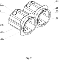
- the flush-mounted junction box 1 there is at least one female dovetail 26, and on the opposite side of the body 2 there is at least one corresponding male dovetail 27.
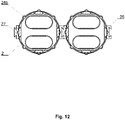
- the applied dovetails allow to join said junction boxes to form a module as shown in Fig. 11 and 12 .
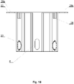
- Fig. 13-16 present a flush-mounted junction box as in embodiment 1, but this one's supports 38 have slanted notches 41 instead of pilot holes 39.
- the effect of the slanted notches 41 is that the tip of the screw 40 (for attaching electrical equipment) passing through the fastenings in the form of teeth 35 slides on the slanted surface of the notch 41 , thus causing the fastening in the form of teeth 35 to be pulled away from the axis of symmetry of the slide-out element 3, thus ensuring durable anchorage of the slide-out element 3 in the body 2.
- the purpose of the narrowings 331 is to allow to drive in the screws 40 that attach electrical equipment, and consequently to ensure firm fixing of the screws 40 in the junction box 1, and thus a correct and durable installation of electrical elements in the box 1.
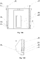
- Fig. 17-18 depict the body 2 of the flush-mounted junction box as in embodiments 1 to 3, in which the female dovetail 26 and the male dovetail 27 have coaxial pass-through openings 6. After the bodies 2 have been joined together, the coaxial pass-through openings 6 allow to easily run cables between them.
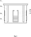
- Fig. 19 depicts the body 2 of the flush-mounted junction box as in embodiments 1 to 4, in which the supporting flange 22 additionally has the first pour-in opening 29a and the second pour-in opening 29b , wherein the second pour-in opening 29b is filled with a removable plug.
- the first pour-in opening 29a and the second pour-in opening 29b are located on opposite sections of the supporting flange 22 along a single axis of symmetry.
- the pour-in openings 29a and 29b allow to introduce glue mass in order to permanently embed the body 2 of the flush-mounted junction box 1 in the wall.
- the first pour-in opening 29a also indicates the part of the flush-mounted junction box 1 that should be on top after installation.
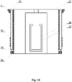
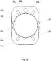
- Fig. 20 depicts the body 2 of the flush-mounted junction box 1 as in embodiments 1 to 5, in which the supporting flange 22 has two pairs of opposite openings 71 designed to receive wedges 8 during the provisional insertion of the body 2 in the wall. On the external surface of the body 2 there are also bases 28 that are aligned with the openings 71 (as shown in Fig. 20 ). The pairs of opposite openings 71 are located on the diagonals of the supporting flange 22.
- Fig. 21 depicts the body 2 provisionally placed in the wall using wedges 8 inserted into the openings 71.
- the body 2 of the junction box 1 is inserted into a recess in the masonry wall 5, and then the wedges 8 are inserted into the openings 71 so that they rest against the base 28 and the masonry wall 5 thus forming a rigid connection.
- glue mass can be introduced into the first pour-in opening 29a and/or the second pour-in opening 29b in order to permanently embed the body 2 in the masonry wall 5.
Description
- The subject matter of the invention is a flush-mounted junction box.
- Chinese utility model
CN204732809 describes a junction box designed to be installed in a wall, which junction box has a body allowing it to be set in the wall and a slide-out element with teeth that allow to block said slide-out element in an appropriate position in relation to the body. In addition, said junction box may have a circular cross-section. - Chinese patent
CN105391009 describes a junction box which has a body and an expansion box as a slide-out element. The position of the expansion box in relation to the body is adjusted by means of connectors and corresponding openings. - Chinese utility model
CN204578020 describes a distribution box designed to be installed in a wall, which distribution box has a body and a slide-out element with teeth that allow the size of this box to be adjusted. - Chinese utility model
CN206585291 describes a flush-mounted junction box, which has a body and a slide-out element in the form of a sleeve with cylindrical blocking elements that allow to maintain an appropriate length of said slide-out element in relation to the body. Thanks to this, the size of the box can be adjusted to the current depth of the recess in which it is being embedded. - Moreover, Chinese patent
CN105896424B describes an adjustable-length junction box, which includes a body and a slide-apart element that makes it possible to adjust the size of the box. The box can be installed in walls. - French patent
FR2868618 - Since state-of-the-art solutions allow to put the slide-out element in the body of the box only permanently in a specific position, it would be purposeful to develop an adjustable flush-mounted junction box which allows a provisional (trial) insertion of the slide-out element into the body of the box without the body and the element interlocking when the element is being slid in.
- The subject matter of the invention is a flush-mounted junction box that has a body in the form of a cylinder with an inlet opening connected to a supporting flange at its first end, having on its internal surface: longitudinal first grooves and sets of fastenings in the form of teeth. The box also contains a slide-out element in the form of a cylinder with a pass-through opening, having on its external surface: longitudinal ribs that make up fitted connections with the first grooves, as well as sets of fastenings in the form of teeth that - together with the other sets of fastenings in the form of teeth - make up toothed connections, wherein the sets of fastenings in the form of teeth are located on elements whose contours are outlined by openings. The flush-mounted junction box is characterized by the fact that the first grooves run along the fastenings in the form of teeth, and that the body has second grooves that are offset in relation to the first grooves by an angle that prevents the sets of fastenings of the body and the sets of fastenings of the slide-out element from interlocking, wherein the second grooves make up fitted connections with the ribs.
- Such a design of the box makes it possible to carry out a trial that involves provisionally inserting the slide-out element into the body of the box without the body and the element interlocking when the element is being slid in.
- Preferably, the second grooves are offset in relation to the first grooves by 45°.
- Preferably, the first grooves run along the fastenings in the form of teeth in their axis of symmetry.
- Preferably, the box has four first grooves, four second grooves, and four fastenings in the form of teeth.
- Preferably, the grooves and/or the fastenings in the form of teeth are evenly distributed.
- Preferably, at the end opposite the end with the supporting flange, the body has removable plugs.
- Preferably, the slide-out element has evenly distributed thickenings on the internal surface.
- Preferably, the thickenings have the form of longitudinal bars that are convex on one side and flat on the other.
- Preferably, the thickenings also have longitudinal pass-through openings for screws to make it possible to attach electrical equipment and to block the sets of fastenings in the form of teeth.
- Preferably, the longitudinal pass-through openings have narrowings. The purpose of the narrowings is to allow to drive in the screws that attach electrical equipment, and consequently to ensure firm fixing of the screws in the junction box, and thus a correct and durable installation of electrical elements in the box.
- Preferably, the sections of the walls of the slide-out element that are located opposite to the elements function as supports in which there are pilot holes (coaxial with the pass-through openings) whose purpose is to allow the screws to firmly rest. Alternatively, in the supports there are slanted notches. The effect of the slanted notches is that the tip of the screw (for attaching electrical equipment) passing through the fastenings in the form of teeth slides on the slanted surface of the notch, thus causing the fastening in the form of teeth to be pulled away from the axis of symmetry of the slide-out element, thus ensuring durable anchorage of the slide-out element in the body.
- Preferably, on the external surface of the body there is at least one female dovetail and at least one corresponding male dovetail located on the opposite side of the body.
- Preferably, the female dovetail and the male dovetail have coaxial pass-through openings, which allow to easily run cables between interconnected boxes.
- Preferably, the supporting flange has the first pour-in opening and/or the second pour-in opening, wherein the second pour-in opening is filled with a removable plug. The pour-in opening allows to introduce glue mass in order to permanently embed the body of the box in the wall. In addition, the first pour-in opening also indicates the part of the box that should be on top after installation.
- Preferably, the first pour-in opening and/or the second pour-in opening are located in the axes of symmetry of the supporting flange, wherein, the most preferably, the first pour-in opening and the second pour-in opening are located on opposite sections of the supporting flange along a single axis of symmetry.
- Preferably, the supporting flange has two pairs of opposite openings designed to receive wedges during the provisional insertion of the body in the wall, and on the external surface of the body there are bases that are aligned with the openings and designed to support the wedges during the provisional insertion of the body in the wall, wherein the pairs of opposite openings are located on at least two diagonals of the supporting flange.
- Embodiments of the subject matter of the invention are presented in the drawing where:
-
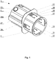
Fig. 1 shows the flush-mounted junction box in a perspective view, when the sets of fastenings of the body and the sets of fastenings of the slide-out element are interlocked; -
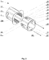
Fig. 2 shows the flush-mounted junction box in an exploded view, when the sets of fastenings of the body and the sets of fastenings of the slide-out element are positioned in a way that allows them to become interlocked; -
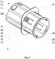
Fig. 3 shows the flush-mounted junction box in a perspective view, when the sets of fastenings of the body and the sets of fastenings of the slide-out element are positioned in a way that allows to carry out a trial that involves provisionally inserting the slide-out element into the body of the box; -
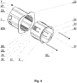
Fig. 4 shows the flush-mounted junction box in an exploded view, when the sets of fastenings of the body and the sets of fastenings of the slide-out element are positioned in a way that allows to carry out a trial that involves provisionally inserting the slide-out element into the body of the box; -
Fig. 5 shows the flush-mounted junction box viewed from behind, when the sets of fastenings of the body and the sets of fastenings of the slide-out element are interlocked; -
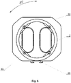
Fig. 6 shows the flush-mounted junction box viewed from behind, when the sets of fastenings of the body and the sets of fastenings of the slide-out element are positioned in a way that allows to carry out a trial that involves provisionally inserting the slide-out element into the body of the box; -
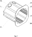
Fig. 7 shows the body of the flush-mounted junction box in a perspective view; -
Fig. 8 shows the slide-out element of the flush-mounted junction box in a perspective view; -
Fig. 9 shows the slide-out element of the flush-mounted junction box viewed from the side; -
Fig. 10 shows the slide-out element of the flush-mounted junction box in a cross-sectional view. -
Fig. 11 shows the flush-mounted junction boxes joined to form a module, in a perspective view; -
Fig. 12 shows the flush-mounted junction boxes joined to form a module, viewed from behind. -
Fig. 13 shows the slide-out element of the flush-mounted junction box according to the second embodiment, in a cross-sectional view. -
Fig. 14 shows the slide-out element of the flush-mounted junction box according to the second embodiment, in a perspective view; -
Fig. 15A shows the slide-out element of the flush-mounted junction box according to the second and/or third embodiment, in a cross-sectional view; -
Fig. 15B depicts the narrowing that fixes the screw in the slide-out element according to the second and/or third embodiment, in an enlarged cross-sectional view; -
Fig. 16 shows the slide-out element of the flush-mounted junction box according to the second embodiment, in a cross-sectional view; -
Fig. 17 shows the body of the flush-mounted junction box according to the fourth embodiment, in a perspective view; -
Fig. 18 shows the body of the flush-mounted junction box according to the fourth embodiment, viewed from the side; -
Fig. 19 shows the body of the flush-mounted junction box according to the fifth embodiment, in a perspective view; -
Fig. 20 shows the flush-mounted junction box according to the sixth embodiment, viewed from behind; -
Fig. 21 shows diagrammatically the wedging of the junction box of the invention. - The flush-mounted
junction box 1 contains thebody 2 and the slide-outelement 3. Thebody 2 has the form of a cylinder with the inlet opening 21 connected to the supportingflange 22 located at the first end of thebody 2. The supportingflange 22 allows to rest the box against the wall, for faster and more accurate installation. Moreover, at the second end of thebody 2, there areremovable plugs 23. After these have been removed, electric cables can be routed through the resulting openings. Along the internal surface of thebody 2, there are four evenly distributedfirst grooves 24a, four evenly distributedsecond grooves 24b, and four evenly distributed sets of fastenings in the form ofteeth 25, wherein thegrooves 24a run along the fastenings in the form ofteeth 25, preferably in their axes of symmetry, and thegrooves 24b are offset in relation to thegrooves 24a by an angle that makes it impossible for the sets offastenings 25 of thebody 2 and the sets offastenings 35 of the slide-outelement 3 to become interlocked, preferably by 45°. - The slide-out
element 3 of the flush-mountedjunction box 1 has the form of a cylinder with a pass-throughopening 31. On the external surface of the slide-outelement 3, four evenly distributedribs 34 run along the height of the cylinder and make up fitted connections with thegrooves element 3, there are also evenly distributed sets of fastenings in the form ofteeth 35 which - together with the sets of fastenings in the form of teeth 25 - make up toothed connections. Wherein the sets of fastenings in the form ofteeth 35 are located on theelements 36 the shape of which is outlined by theopenings 37, thus allowing to reduce the rigidity of theelements 36 and making it possible to insert the slide-outelement 3 into thebody 2 in a position that prevents the sets offastenings 25 of thebody 2 and the sets offastenings 35 of the slide-outelement 3 from interlocking. - The
grooves 24b of thebody 2 allow to put the slide-outelement 3 inside thebody 2 in a position that prevents the sets offastenings 25 of thebody 2 and the sets offastenings 35 of the slide-outelement 3 from interlocking, which makes it possible to provisionally determine the status of thebody 2 inserted into the wall (to check whether it fits properly). - In turn, the
grooves 24a of thebody 2 allow to place the slide-outelement 3 in thebody 2 in a position where said sets of fastenings 25and 35 become interlocked, which results in permanently positioning the slide-outelement 3 in thebody 2. - What is more, on the internal surface of the slide-out
element 3 there are four evenly distributedthickenings 32, which have the form of bars that are convex on one side and flat on the other, and which run along the height of the slide-outelement 3. Thethickenings 32 allow to install electrical equipment using clamps. Thethickenings 32 also have longitudinal pass-throughopenings 33 forscrews 40 to make it possible to attach electrical equipment and to block the sets of fastenings in the form ofteeth 25. - The sections of the walls of the slide-out
element 3 that are located opposite to theelements 36 function as supports 38 in which there are pilot holes 39 (coaxial with the openings 33) whose purpose is to allow thescrews 40 to firmly rest. The pilot holes 39 allow thescrews 40 to rest in such a way that they block the sets offastenings 25 of thebody 2. - Said sets of
fastenings 25 of the body 2 - together with the sets offastenings 35 of the slide-out element 3 - allow to adjust the length of said flush-mountedjunction box 1 while maintaining a stable position of the slide-outelement 3 in thebody 2. - In addition, on the external surface of the
body 2 of the flush-mountedjunction box 1 there is at least onefemale dovetail 26, and on the opposite side of thebody 2 there is at least one correspondingmale dovetail 27. The applied dovetails allow to join said junction boxes to form a module as shown inFig. 11 and12 . -
Fig. 13-16 present a flush-mounted junction box as inembodiment 1, but this one'ssupports 38 have slantednotches 41 instead of pilot holes 39. The effect of the slantednotches 41 is that the tip of the screw 40 (for attaching electrical equipment) passing through the fastenings in the form ofteeth 35 slides on the slanted surface of thenotch 41, thus causing the fastening in the form ofteeth 35 to be pulled away from the axis of symmetry of the slide-outelement 3, thus ensuring durable anchorage of the slide-outelement 3 in thebody 2. - A flush-mounted junction box as in
embodiment 1, in which the longitudinal pass-throughopenings 33 havenarrowings 331 as illustrated inFig. 15 . The purpose of thenarrowings 331 is to allow to drive in thescrews 40 that attach electrical equipment, and consequently to ensure firm fixing of thescrews 40 in thejunction box 1, and thus a correct and durable installation of electrical elements in thebox 1. -
Fig. 17-18 depict thebody 2 of the flush-mounted junction box as inembodiments 1 to 3, in which thefemale dovetail 26 and themale dovetail 27 have coaxial pass-throughopenings 6. After thebodies 2 have been joined together, the coaxial pass-throughopenings 6 allow to easily run cables between them. -
Fig. 19 depicts thebody 2 of the flush-mounted junction box as inembodiments 1 to 4, in which the supportingflange 22 additionally has the first pour-inopening 29a and the second pour-inopening 29b, wherein the second pour-inopening 29b is filled with a removable plug. The first pour-inopening 29a and the second pour-inopening 29b are located on opposite sections of the supportingflange 22 along a single axis of symmetry. The pour-inopenings body 2 of the flush-mountedjunction box 1 in the wall. In addition, the first pour-inopening 29a also indicates the part of the flush-mountedjunction box 1 that should be on top after installation. -
Fig. 20 depicts thebody 2 of the flush-mountedjunction box 1 as inembodiments 1 to 5, in which the supportingflange 22 has two pairs ofopposite openings 71 designed to receivewedges 8 during the provisional insertion of thebody 2 in the wall. On the external surface of thebody 2 there are also bases 28 that are aligned with the openings 71 (as shown inFig. 20 ). The pairs ofopposite openings 71 are located on the diagonals of the supportingflange 22. -
Fig. 21 depicts thebody 2 provisionally placed in thewall using wedges 8 inserted into theopenings 71. In order to install the flush-mountedjunction box 1 in thewall 5, thebody 2 of thejunction box 1 is inserted into a recess in themasonry wall 5, and then thewedges 8 are inserted into theopenings 71 so that they rest against thebase 28 and themasonry wall 5 thus forming a rigid connection. - After the
body 2 has been provisionally inserted into themasonry wall 5, glue mass can be introduced into the first pour-inopening 29a and/or the second pour-inopening 29b in order to permanently embed thebody 2 in themasonry wall 5.
Claims (15)
- A flush-mounted junction box (1), which includes:- a body (2) in the form of a cylinder with an inlet opening (21) connected to a supporting flange (22) at its first end, having on its internal surface: longitudinal first grooves (24a) and sets of fastenings in the form of teeth (25);- a slide-out element (3) in the form of a cylinder with a pass-through opening (31), having on its external surface: longitudinal ribs (34) that make up fitted connections with the first grooves (24a), as well as sets of fastenings in the form of teeth (35) that, together with the sets of fastenings in the form of teeth (25) of the body (2), make up toothed connections, wherein the sets of fastenings in the form of teeth (35) of the slide-out element (3) are located on elements (36) whose contours are outlined by openings (37);wherein- the first grooves (24a) run along the fastenings in the form of teeth (25) of the body (2)and the body (2) has second grooves (24b) that are offset in relation to the first grooves (24a) by an angle that prevents the sets of fastenings (25) of the body (2) and the sets of fastenings (35) of the slide-out element (3) from interlocking, wherein the second grooves (24b) make up fitted connections with the ribs (34).
- The flush-mounted junction box according to claim 1, characterized that the second grooves (24b) are offset in relation to the first grooves (24a) by 45°.
- The flush-mounted junction box according to claims 1 or 2, characterized that the first grooves (24a) run along the fastenings in the form of teeth (25) of the body (2) in their axis of symmetry.
- The flush-mounted junction box according to claims 1 or 2 or 3, characterized that the body (2) has four first grooves (24a), four second grooves (24b), and four fastenings in the form of teeth (25).
- The flush-mounted junction box according to any of the claims from 1 to 4, characterized that the grooves (24a, 24b, 34) and/or the fastenings in the form of teeth (25, 35) are evenly distributed.
- The flush-mounted junction box according to any of the claims from 1 to 5, characterized that at the end opposite the end with the supporting flange (22) the body (2) has removable plugs (23).
- The flush-mounted junction box according to any of the claims from 1 to 6, characterized that the slide-out element (3) has evenly distributed thickenings (32) on the internal surface.
- The flush-mounted junction box according to claim 7, characterized that the thickenings (32) preferably have the form of longitudinal bars that are convex on one side and flat on the other.
- The flush-mounted junction box according to claims 7 or 8, characterized that the thickenings (32) also have longitudinal pass-through openings (33) for screws (40) to make it possible to attach electrical equipment and to block the sets of fastenings in the form of teeth (25) of the body (2).
- The flush-mounted junction box according to claim 9, characterized that the longitudinal pass-through openings (33) also have a narrowing (331).
- The flush-mounted junction box according to any of the claims from 7 to 10, characterized that the sections of the walls of the slide-out element (3) that are located opposite to the elements (36) function as supports (38) in which:- there are pilot holes (39), which are coaxial with the openings (33), and whose purpose is to allow the screws (40) to firmly rest, or- there are slanted notches (41).
- The flush-mounted junction box according to any of the claims from 1 to 11, characterized that on the external surface of the body (2) there is at least one female dovetail (26) and at least one corresponding male dovetail (27) located on the opposite side of the body (2).
- The flush-mounted junction box according to claim 12, characterized that the female dovetail (26) and the male dovetail (27) have coaxial pass-through openings (6).
- The flush-mounted junction box according to any of the claims from 1 to 13, characterized that the supporting flange (22) has the first pour-in opening (29A) and/or the second pour-in opening (29B), wherein the second pour-in opening (29B) is filled with a removable plug; preferably, the first pour-in opening (29A) and/or the second pour-in opening (29B) are located in the axes of symmetry of the supporting flange (22); the most preferably, the first pour-in opening (29A) and the second pour-in opening (29B) are located on opposite sections of the supporting flange (22) along a single axis of symmetry.
- The flush-mounted junction box according to any of the claims from 1 to 14, characterized that the supporting flange (22) has two pairs of opposite openings (71) designed to receive wedges (8) during the provisional insertion of the body (2) in the wall, and that on the external surface of the body (2) there are bases (28) that are aligned with the openings (71) and designed to support the wedges (8) during the provisional insertion of the body (2) in the wall, wherein the pairs of opposite openings (71) are located on at least two diagonals of the supporting flange (22).
Applications Claiming Priority (1)
| Application Number | Priority Date | Filing Date | Title |
|---|---|---|---|
| PL429038A PL237388B1 (en) | 2019-02-26 | 2019-02-26 | In-wall electrical junction box |
Publications (2)
| Publication Number | Publication Date |
|---|---|
| EP3703207A1 EP3703207A1 (en) | 2020-09-02 |
| EP3703207B1 true EP3703207B1 (en) | 2022-09-21 |
Family
ID=70333763
Family Applications (1)
| Application Number | Title | Priority Date | Filing Date |
|---|---|---|---|
| EP20159652.5A Active EP3703207B1 (en) | 2019-02-26 | 2020-02-26 | Flush-mounted junction box |
Country Status (2)
| Country | Link |
|---|---|
| EP (1) | EP3703207B1 (en) |
| PL (1) | PL237388B1 (en) |
Families Citing this family (2)
| Publication number | Priority date | Publication date | Assignee | Title |
|---|---|---|---|---|
| US11557888B2 (en) | 2019-02-14 | 2023-01-17 | Erico International Corporation | Adjustable depth electrical wall mount ring |
| CN112952730B (en) * | 2021-01-21 | 2023-04-07 | 武汉船用机械有限责任公司 | Terminal box |
Citations (1)
| Publication number | Priority date | Publication date | Assignee | Title |
|---|---|---|---|---|
| FR2868618B1 (en) * | 2004-03-30 | 2006-05-26 | Capri Codec Sas Soc Par Action | ADJUSTABLE INDEXABLE PLASTIC HOLDER ASSEMBLY OF ELEMENTS SUCH AS ELECTRICAL EQUIPMENT HOUSINGS BETWEEN BANKS |
Family Cites Families (7)
| Publication number | Priority date | Publication date | Assignee | Title |
|---|---|---|---|---|
| US5783774A (en) * | 1996-10-21 | 1998-07-21 | Walker Systems, Inc. | Non-metallic floor box |
| CN204578020U (en) | 2015-03-11 | 2015-08-19 | 中铁上海工程局集团有限公司 | A kind of adjustable type wall pre-embedded conjunction box |
| US9667053B2 (en) * | 2015-06-01 | 2017-05-30 | Hubbell Incorporated | Adjustable floor box |
| CN204732809U (en) | 2015-06-09 | 2015-10-28 | 张少伟 | A kind of electrical appliance junction box |
| CN105391009B (en) | 2015-12-08 | 2017-11-24 | 重庆市巴南区环美金属加工厂 | A kind of scalable 86 back box being easily installed |
| CN105896424B (en) | 2016-05-31 | 2018-11-09 | 福建西河卫浴科技有限公司 | A kind of embedded box installation and adjustment structure |
| CN206585291U (en) | 2017-03-24 | 2017-10-24 | 业之峰诺华家居装饰集团股份有限公司 | Tractile dust-proof Built-in terminal box |
-
2019
- 2019-02-26 PL PL429038A patent/PL237388B1/en unknown
-
2020
- 2020-02-26 EP EP20159652.5A patent/EP3703207B1/en active Active
Patent Citations (1)
| Publication number | Priority date | Publication date | Assignee | Title |
|---|---|---|---|---|
| FR2868618B1 (en) * | 2004-03-30 | 2006-05-26 | Capri Codec Sas Soc Par Action | ADJUSTABLE INDEXABLE PLASTIC HOLDER ASSEMBLY OF ELEMENTS SUCH AS ELECTRICAL EQUIPMENT HOUSINGS BETWEEN BANKS |
Also Published As
| Publication number | Publication date |
|---|---|
| PL237388B1 (en) | 2021-04-06 |
| PL429038A1 (en) | 2020-09-07 |
| EP3703207A1 (en) | 2020-09-02 |
Similar Documents
| Publication | Publication Date | Title |
|---|---|---|
| EP3703207B1 (en) | Flush-mounted junction box | |
| KR100674253B1 (en) | Unified strain crossarm in which a location of an insulator at an electric power distribution line is changed easily | |
| KR101984419B1 (en) | Fixing frame for plug connector | |
| US20170077688A1 (en) | Electric Device | |
| US20200227901A9 (en) | Networking enclosure assembly with magnetic alignment and interlocking, adaptable to be installed in different locations and positions | |
| CA2987924A1 (en) | Adjustable floor box | |
| BR112019019485A2 (en) | connectors for a single twisted pair of conductors, adapter, and harnesses | |
| WO2019175847A1 (en) | Electric connector | |
| EP3055913B1 (en) | Multi-member channel bar | |
| BR112019014298A2 (en) | FIXING ASSEMBLY AND METHOD OF USING A FIXING ASSEMBLY. | |
| CN211320845U (en) | Adjustable junction box panel | |
| EP1109270A2 (en) | Socket-outlet for lighting fixture | |
| US9368949B2 (en) | Channel system | |
| JP2000509561A (en) | Mounting unit with mounting rail | |
| KR20110123627A (en) | A coupling device and assembling method of it | |
| RU2707222C2 (en) | Connecting element for mechanical connection of frames of distribution devices | |
| CN216530812U (en) | Motor support stable in assembly | |
| GB2561140A (en) | Fence post and clip system | |
| EP3926760A1 (en) | Adaptor for connecting an electrical plug with a flexible prewired conduit | |
| CN219576064U (en) | Cable connection structure | |
| JPS6224949Y2 (en) | ||
| JP6758641B2 (en) | Water tap installation aid | |
| CN220150808U (en) | Steel pipe support for building formwork | |
| AU2018100721A4 (en) | Cable Junction | |
| KR200452701Y1 (en) | Cable Connection Module |
Legal Events
| Date | Code | Title | Description |
|---|---|---|---|
| PUAI | Public reference made under article 153(3) epc to a published international application that has entered the european phase |
Free format text: ORIGINAL CODE: 0009012 |
|
| STAA | Information on the status of an ep patent application or granted ep patent |
Free format text: STATUS: THE APPLICATION HAS BEEN PUBLISHED |
|
| AK | Designated contracting states |
Kind code of ref document: A1 Designated state(s): AL AT BE BG CH CY CZ DE DK EE ES FI FR GB GR HR HU IE IS IT LI LT LU LV MC MK MT NL NO PL PT RO RS SE SI SK SM TR |
|
| AX | Request for extension of the european patent |
Extension state: BA ME |
|
| STAA | Information on the status of an ep patent application or granted ep patent |
Free format text: STATUS: REQUEST FOR EXAMINATION WAS MADE |
|
| RBV | Designated contracting states (corrected) |
Designated state(s): AL AT BE BG CH CY CZ DE DK EE ES FI FR GB GR HR HU IE IS IT LI LT LU LV MC MK MT NL NO PL PT RO RS SE SI SK SM TR |
|
| 17P | Request for examination filed |
Effective date: 20210210 |
|
| GRAP | Despatch of communication of intention to grant a patent |
Free format text: ORIGINAL CODE: EPIDOSNIGR1 |
|
| STAA | Information on the status of an ep patent application or granted ep patent |
Free format text: STATUS: GRANT OF PATENT IS INTENDED |
|
| INTG | Intention to grant announced |
Effective date: 20211015 |
|
| RIN1 | Information on inventor provided before grant (corrected) |
Inventor name: DUDEK, KRZYSZTOF |
|
| GRAS | Grant fee paid |
Free format text: ORIGINAL CODE: EPIDOSNIGR3 |
|
| GRAJ | Information related to disapproval of communication of intention to grant by the applicant or resumption of examination proceedings by the epo deleted |
Free format text: ORIGINAL CODE: EPIDOSDIGR1 |
|
| GRAL | Information related to payment of fee for publishing/printing deleted |
Free format text: ORIGINAL CODE: EPIDOSDIGR3 |
|
| STAA | Information on the status of an ep patent application or granted ep patent |
Free format text: STATUS: REQUEST FOR EXAMINATION WAS MADE |
|
| INTC | Intention to grant announced (deleted) | ||
| GRAP | Despatch of communication of intention to grant a patent |
Free format text: ORIGINAL CODE: EPIDOSNIGR1 |
|
| STAA | Information on the status of an ep patent application or granted ep patent |
Free format text: STATUS: GRANT OF PATENT IS INTENDED |
|
| GRAS | Grant fee paid |
Free format text: ORIGINAL CODE: EPIDOSNIGR3 |
|
| INTG | Intention to grant announced |
Effective date: 20220412 |
|
| GRAA | (expected) grant |
Free format text: ORIGINAL CODE: 0009210 |
|
| STAA | Information on the status of an ep patent application or granted ep patent |
Free format text: STATUS: THE PATENT HAS BEEN GRANTED |
|
| AK | Designated contracting states |
Kind code of ref document: B1 Designated state(s): AL AT BE BG CH CY CZ DE DK EE ES FI FR GB GR HR HU IE IS IT LI LT LU LV MC MK MT NL NO PL PT RO RS SE SI SK SM TR |
|
| REG | Reference to a national code |
Ref country code: GB Ref legal event code: FG4D |
|
| REG | Reference to a national code |
Ref country code: CH Ref legal event code: EP |
|
| REG | Reference to a national code |
Ref country code: IE Ref legal event code: FG4D |
|
| REG | Reference to a national code |
Ref country code: DE Ref legal event code: R096 Ref document number: 602020005192 Country of ref document: DE |
|
| REG | Reference to a national code |
Ref country code: AT Ref legal event code: REF Ref document number: 1520442 Country of ref document: AT Kind code of ref document: T Effective date: 20221015 |
|
| REG | Reference to a national code |
Ref country code: LT Ref legal event code: MG9D |
|
| REG | Reference to a national code |
Ref country code: NL Ref legal event code: MP Effective date: 20220921 |
|
| PG25 | Lapsed in a contracting state [announced via postgrant information from national office to epo] |
Ref country code: SE Free format text: LAPSE BECAUSE OF FAILURE TO SUBMIT A TRANSLATION OF THE DESCRIPTION OR TO PAY THE FEE WITHIN THE PRESCRIBED TIME-LIMIT Effective date: 20220921 Ref country code: RS Free format text: LAPSE BECAUSE OF FAILURE TO SUBMIT A TRANSLATION OF THE DESCRIPTION OR TO PAY THE FEE WITHIN THE PRESCRIBED TIME-LIMIT Effective date: 20220921 Ref country code: NO Free format text: LAPSE BECAUSE OF FAILURE TO SUBMIT A TRANSLATION OF THE DESCRIPTION OR TO PAY THE FEE WITHIN THE PRESCRIBED TIME-LIMIT Effective date: 20221221 Ref country code: LV Free format text: LAPSE BECAUSE OF FAILURE TO SUBMIT A TRANSLATION OF THE DESCRIPTION OR TO PAY THE FEE WITHIN THE PRESCRIBED TIME-LIMIT Effective date: 20220921 Ref country code: LT Free format text: LAPSE BECAUSE OF FAILURE TO SUBMIT A TRANSLATION OF THE DESCRIPTION OR TO PAY THE FEE WITHIN THE PRESCRIBED TIME-LIMIT Effective date: 20220921 Ref country code: FI Free format text: LAPSE BECAUSE OF FAILURE TO SUBMIT A TRANSLATION OF THE DESCRIPTION OR TO PAY THE FEE WITHIN THE PRESCRIBED TIME-LIMIT Effective date: 20220921 |
|
| REG | Reference to a national code |
Ref country code: AT Ref legal event code: MK05 Ref document number: 1520442 Country of ref document: AT Kind code of ref document: T Effective date: 20220921 |
|
| PG25 | Lapsed in a contracting state [announced via postgrant information from national office to epo] |
Ref country code: HR Free format text: LAPSE BECAUSE OF FAILURE TO SUBMIT A TRANSLATION OF THE DESCRIPTION OR TO PAY THE FEE WITHIN THE PRESCRIBED TIME-LIMIT Effective date: 20220921 Ref country code: GR Free format text: LAPSE BECAUSE OF FAILURE TO SUBMIT A TRANSLATION OF THE DESCRIPTION OR TO PAY THE FEE WITHIN THE PRESCRIBED TIME-LIMIT Effective date: 20221222 |
|
| PG25 | Lapsed in a contracting state [announced via postgrant information from national office to epo] |
Ref country code: SM Free format text: LAPSE BECAUSE OF FAILURE TO SUBMIT A TRANSLATION OF THE DESCRIPTION OR TO PAY THE FEE WITHIN THE PRESCRIBED TIME-LIMIT Effective date: 20220921 Ref country code: RO Free format text: LAPSE BECAUSE OF FAILURE TO SUBMIT A TRANSLATION OF THE DESCRIPTION OR TO PAY THE FEE WITHIN THE PRESCRIBED TIME-LIMIT Effective date: 20220921 Ref country code: PT Free format text: LAPSE BECAUSE OF FAILURE TO SUBMIT A TRANSLATION OF THE DESCRIPTION OR TO PAY THE FEE WITHIN THE PRESCRIBED TIME-LIMIT Effective date: 20230123 Ref country code: ES Free format text: LAPSE BECAUSE OF FAILURE TO SUBMIT A TRANSLATION OF THE DESCRIPTION OR TO PAY THE FEE WITHIN THE PRESCRIBED TIME-LIMIT Effective date: 20220921 Ref country code: CZ Free format text: LAPSE BECAUSE OF FAILURE TO SUBMIT A TRANSLATION OF THE DESCRIPTION OR TO PAY THE FEE WITHIN THE PRESCRIBED TIME-LIMIT Effective date: 20220921 Ref country code: AT Free format text: LAPSE BECAUSE OF FAILURE TO SUBMIT A TRANSLATION OF THE DESCRIPTION OR TO PAY THE FEE WITHIN THE PRESCRIBED TIME-LIMIT Effective date: 20220921 |
|
| PG25 | Lapsed in a contracting state [announced via postgrant information from national office to epo] |
Ref country code: SK Free format text: LAPSE BECAUSE OF FAILURE TO SUBMIT A TRANSLATION OF THE DESCRIPTION OR TO PAY THE FEE WITHIN THE PRESCRIBED TIME-LIMIT Effective date: 20220921 Ref country code: PL Free format text: LAPSE BECAUSE OF FAILURE TO SUBMIT A TRANSLATION OF THE DESCRIPTION OR TO PAY THE FEE WITHIN THE PRESCRIBED TIME-LIMIT Effective date: 20220921 Ref country code: IS Free format text: LAPSE BECAUSE OF FAILURE TO SUBMIT A TRANSLATION OF THE DESCRIPTION OR TO PAY THE FEE WITHIN THE PRESCRIBED TIME-LIMIT Effective date: 20230121 Ref country code: EE Free format text: LAPSE BECAUSE OF FAILURE TO SUBMIT A TRANSLATION OF THE DESCRIPTION OR TO PAY THE FEE WITHIN THE PRESCRIBED TIME-LIMIT Effective date: 20220921 |
|
| PGFP | Annual fee paid to national office [announced via postgrant information from national office to epo] |
Ref country code: DE Payment date: 20221212 Year of fee payment: 4 |
|
| REG | Reference to a national code |
Ref country code: DE Ref legal event code: R097 Ref document number: 602020005192 Country of ref document: DE |
|
| PG25 | Lapsed in a contracting state [announced via postgrant information from national office to epo] |
Ref country code: NL Free format text: LAPSE BECAUSE OF FAILURE TO SUBMIT A TRANSLATION OF THE DESCRIPTION OR TO PAY THE FEE WITHIN THE PRESCRIBED TIME-LIMIT Effective date: 20220921 Ref country code: AL Free format text: LAPSE BECAUSE OF FAILURE TO SUBMIT A TRANSLATION OF THE DESCRIPTION OR TO PAY THE FEE WITHIN THE PRESCRIBED TIME-LIMIT Effective date: 20220921 |
|
| PLBE | No opposition filed within time limit |
Free format text: ORIGINAL CODE: 0009261 |
|
| STAA | Information on the status of an ep patent application or granted ep patent |
Free format text: STATUS: NO OPPOSITION FILED WITHIN TIME LIMIT |
|
| PG25 | Lapsed in a contracting state [announced via postgrant information from national office to epo] |
Ref country code: DK Free format text: LAPSE BECAUSE OF FAILURE TO SUBMIT A TRANSLATION OF THE DESCRIPTION OR TO PAY THE FEE WITHIN THE PRESCRIBED TIME-LIMIT Effective date: 20220921 |
|
| 26N | No opposition filed |
Effective date: 20230622 |
|
| PG25 | Lapsed in a contracting state [announced via postgrant information from national office to epo] |
Ref country code: SI Free format text: LAPSE BECAUSE OF FAILURE TO SUBMIT A TRANSLATION OF THE DESCRIPTION OR TO PAY THE FEE WITHIN THE PRESCRIBED TIME-LIMIT Effective date: 20220921 |
|
| PG25 | Lapsed in a contracting state [announced via postgrant information from national office to epo] |
Ref country code: MC Free format text: LAPSE BECAUSE OF FAILURE TO SUBMIT A TRANSLATION OF THE DESCRIPTION OR TO PAY THE FEE WITHIN THE PRESCRIBED TIME-LIMIT Effective date: 20220921 |
|
| REG | Reference to a national code |
Ref country code: CH Ref legal event code: PL |
|
| REG | Reference to a national code |
Ref country code: BE Ref legal event code: MM Effective date: 20230228 |
|
| PG25 | Lapsed in a contracting state [announced via postgrant information from national office to epo] |
Ref country code: LU Free format text: LAPSE BECAUSE OF NON-PAYMENT OF DUE FEES Effective date: 20230226 Ref country code: LI Free format text: LAPSE BECAUSE OF NON-PAYMENT OF DUE FEES Effective date: 20230228 Ref country code: CH Free format text: LAPSE BECAUSE OF NON-PAYMENT OF DUE FEES Effective date: 20230228 |
|
| REG | Reference to a national code |
Ref country code: IE Ref legal event code: MM4A |
|
| PG25 | Lapsed in a contracting state [announced via postgrant information from national office to epo] |
Ref country code: IE Free format text: LAPSE BECAUSE OF NON-PAYMENT OF DUE FEES Effective date: 20230226 Ref country code: FR Free format text: LAPSE BECAUSE OF NON-PAYMENT OF DUE FEES Effective date: 20230228 |
|
| PG25 | Lapsed in a contracting state [announced via postgrant information from national office to epo] |
Ref country code: BE Free format text: LAPSE BECAUSE OF NON-PAYMENT OF DUE FEES Effective date: 20230228 |
|
| PGFP | Annual fee paid to national office [announced via postgrant information from national office to epo] |
Ref country code: DE Payment date: 20240122 Year of fee payment: 5 |