EP3703207A1 - Boîte de raccordement encastrée - Google Patents
Boîte de raccordement encastrée Download PDFInfo
- Publication number
- EP3703207A1 EP3703207A1 EP20159652.5A EP20159652A EP3703207A1 EP 3703207 A1 EP3703207 A1 EP 3703207A1 EP 20159652 A EP20159652 A EP 20159652A EP 3703207 A1 EP3703207 A1 EP 3703207A1
- Authority
- EP
- European Patent Office
- Prior art keywords
- flush
- junction box
- fastenings
- grooves
- teeth
- Prior art date
- Legal status (The legal status is an assumption and is not a legal conclusion. Google has not performed a legal analysis and makes no representation as to the accuracy of the status listed.)
- Granted
Links
- 230000008719 thickening Effects 0.000 claims description 9
- 238000003780 insertion Methods 0.000 claims description 6
- 230000037431 insertion Effects 0.000 claims description 6
- 238000009434 installation Methods 0.000 description 5
- 239000003292 glue Substances 0.000 description 3
- 230000000694 effects Effects 0.000 description 2
- 230000000903 blocking effect Effects 0.000 description 1
Images


Classifications
-
- H—ELECTRICITY
- H02—GENERATION; CONVERSION OR DISTRIBUTION OF ELECTRIC POWER
- H02G—INSTALLATION OF ELECTRIC CABLES OR LINES, OR OF COMBINED OPTICAL AND ELECTRIC CABLES OR LINES
- H02G3/00—Installations of electric cables or lines or protective tubing therefor in or on buildings, equivalent structures or vehicles
- H02G3/02—Details
- H02G3/08—Distribution boxes; Connection or junction boxes
- H02G3/086—Assembled boxes
-
- H—ELECTRICITY
- H02—GENERATION; CONVERSION OR DISTRIBUTION OF ELECTRIC POWER
- H02G—INSTALLATION OF ELECTRIC CABLES OR LINES, OR OF COMBINED OPTICAL AND ELECTRIC CABLES OR LINES
- H02G3/00—Installations of electric cables or lines or protective tubing therefor in or on buildings, equivalent structures or vehicles
- H02G3/02—Details
- H02G3/08—Distribution boxes; Connection or junction boxes
- H02G3/12—Distribution boxes; Connection or junction boxes for flush mounting
- H02G3/121—Distribution boxes; Connection or junction boxes for flush mounting in plain walls
Definitions
- the subject matter of the invention is a flush-mounted junction box.
- junction box designed to be installed in a wall, which junction box has a body allowing it to be set in the wall and a slide-out element with teeth that allow to block said slide-out element in an appropriate position in relation to the body.
- said junction box may have a circular cross-section.
- Chinese patent CN105391009 describes a junction box which has a body and an expansion box as a slide-out element. The position of the expansion box in relation to the body is adjusted by means of connectors and corresponding openings.
- Chinese utility model CN204578020 describes a distribution box designed to be installed in a wall, which distribution box has a body and a slide-out element with teeth that allow the size of this box to be adjusted.
- Chinese utility model CN206585291 describes a flush-mounted junction box, which has a body and a slide-out element in the form of a sleeve with cylindrical blocking elements that allow to maintain an appropriate length of said slide-out element in relation to the body. Thanks to this, the size of the box can be adjusted to the current depth of the recess in which it is being embedded.
- Chinese patent CN105896424B describes an adjustable-length junction box, which includes a body and a slide-apart element that makes it possible to adjust the size of the box.
- the box can be installed in walls.
- the subject matter of the invention is a flush-mounted junction box that has a body in the form of a cylinder with an inlet opening connected to a supporting flange at its first end, having on its internal surface: longitudinal first grooves and sets of fastenings in the form of teeth.
- the box also contains a slide-out element in the form of a cylinder with a pass-through opening, having on its external surface: longitudinal ribs that make up fitted connections with the first grooves, as well as sets of fastenings in the form of teeth that - together with the other sets of fastenings in the form of teeth - make up toothed connections, wherein the sets of fastenings in the form of teeth are located on elements whose contours are outlined by openings.
- the flush-mounted junction box is characterized by the fact that the first grooves run along the fastenings in the form of teeth, and that it has the second grooves that are offset in relation to the first grooves by an angle that prevents the sets of fastenings of the body and the sets of fastenings of the slide-out element from interlocking, wherein the second grooves make up fitted connections with the ribs.
- the second grooves are offset in relation to the first grooves by 45°.
- the first grooves run along the fastenings in the form of teeth in their axis of symmetry.
- the box has four first grooves, four second grooves, and four fastenings in the form of teeth.
- the grooves and/or the fastenings in the form of teeth are evenly distributed.
- the body has removable plugs.
- the slide-out element has evenly distributed thickenings on the internal surface.
- the thickenings have the form of longitudinal bars that are convex on one side and flat on the other.
- the thickenings also have longitudinal pass-through openings for screws to make it possible to attach electrical equipment and to block the sets of fastenings in the form of teeth.
- the longitudinal pass-through openings have narrowings.
- the purpose of the narrowings is to allow to drive in the screws that attach electrical equipment, and consequently to ensure firm fixing of the screws in the junction box, and thus a correct and durable installation of electrical elements in the box.
- the sections of the walls of the slide-out element that are located below the elements function as supports in which there are pilot holes (coaxial with the pass-through openings) whose purpose is to allow the screws to firmly rest.
- the supports there are slanted notches. The effect of the slanted notches is that the tip of the screw (for attaching electrical equipment) passing through the fastenings in the form of teeth slides on the slanted surface of the notch, thus causing the fastening in the form of teeth to be pulled away from the axis of symmetry of the slide-out element, thus ensuring durable anchorage of the slide-out element in the body.
- the body there is at least one female dovetail and at least one corresponding male dovetail located on the opposite side of the body.
- the female dovetail and the male dovetail have coaxial pass-through openings, which allow to easily run cables between interconnected boxes.
- the supporting flange has the first pour-in opening and/or the second pour-in opening, wherein the second pour-in opening is filled with a removable plug.
- the pour-in opening allows to introduce glue mass in order to permanently embed the body of the box in the wall.
- the first pour-in opening also indicates the part of the box that should be on top after installation.
- the first pour-in opening and/or the second pour-in opening are located in the axes of symmetry of the supporting flange, wherein, the most preferably, the first pour-in opening and the second pour-in opening are located on opposite sections of the supporting flange along a single axis of symmetry.
- the supporting flange has two pairs of opposite openings designed to receive wedges during the provisional insertion of the body in the wall, and on the external surface of the body there are bases that are aligned with the openings and designed to support the wedges during the provisional insertion of the body in the wall, wherein the pairs of opposite openings are located on at least two diagonals of the supporting flange.
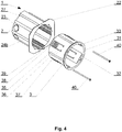
- the flush-mounted junction box 1 contains the body 2 and the slide-out element 3.
- the body 2 has the form of a cylinder with the inlet opening 21 connected to the supporting flange 22 located at the first end of the body 2.
- the supporting flange 22 allows to rest the box against the wall, for faster and more accurate installation.
- first grooves 24a there are four evenly distributed first grooves 24a , four evenly distributed second grooves 24b , and four evenly distributed sets of fastenings in the form of teeth 25, wherein the grooves 24a run along the fastenings in the form of teeth 25, preferably in their axes of symmetry, and the grooves 24b are offset in relation to the grooves 24a by an angle that makes it impossible for the sets of fastenings 25 of the body 2 and the sets of fastenings 35 of the slide-out element 3 to become interlocked, preferably by 45°.
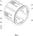
- the slide-out element 3 of the flush-mounted junction box 1 has the form of a cylinder with a pass-through opening 31.
- the sets of fastenings in the form of teeth 35 are located on the elements 36 the shape of which is outlined by the openings 37, thus allowing to reduce the rigidity of the elements 36 and making it possible to insert the slide-out element 3 into the body 2 in a position that prevents the sets of fastenings 25 of the body 2 and the sets of fastenings 35 of the slide-out element 3 from interlocking.
- the grooves 24b of the body 2 allow to put the slide-out element 3 inside the body 2 in a position that prevents the sets of fastenings 25 of the body 2 and the sets of fastenings 35 of the slide-out element 3 from interlocking, which makes it possible to provisionally determine the status of the body 2 inserted into the wall (to check whether it fits properly).
- the grooves 24a of the body 2 allow to place the slide-out element 3 in the body 2 in a position where said sets of fastenings 25 and 35 become interlocked, which results in permanently positioning the slide-out element 3 in the body 2.
- the slide-out element 3 there are four evenly distributed thickenings 32, which have the form of bars that are convex on one side and flat on the other, and which run along the height of the slide-out element 3.
- the thickenings 32 allow to install electrical equipment using clamps.
- the thickenings 32 also have longitudinal pass-through openings 33 for screws 40 to make it possible to attach electrical equipment and to block the sets of fastenings in the form of teeth 25.
- the sections of the walls of the slide-out element 3 that are located below the elements 36 function as supports 38 in which there are pilot holes 39 (coaxial with the openings 33 ) whose purpose is to allow the screws 40 to firmly rest.
- the pilot holes 39 allow the screws 40 to rest in such a way that they block the sets of fastenings 25 of the body 2.
- Said sets of fastenings 25 of the body 2 - together with the sets of fastenings 35 of the slide-out element 3 - allow to adjust the length of said flush-mounted junction box 1 while maintaining a stable position of the slide-out element 3 in the body 2.
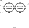
- the flush-mounted junction box 1 there is at least one female dovetail 26, and on the opposite side of the body 2 there is at least one corresponding male dovetail 27.
- the applied dovetails allow to join said junction boxes to form a module as shown in Fig. 11 and 12 .
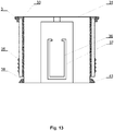
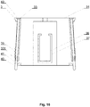
- Fig. 13-16 present a flush-mounted junction box as in embodiment 1, but this one's supports 38 have slanted notches 41 instead of pilot holes 39.
- the effect of the slanted notches 41 is that the tip of the screw 40 (for attaching electrical equipment) passing through the fastenings in the form of teeth 35 slides on the slanted surface of the notch 41 , thus causing the fastening in the form of teeth 35 to be pulled away from the axis of symmetry of the slide-out element 3, thus ensuring durable anchorage of the slide-out element 3 in the body 2.
- the purpose of the narrowings 331 is to allow to drive in the screws 40 that attach electrical equipment, and consequently to ensure firm fixing of the screws 40 in the junction box 1, and thus a correct and durable installation of electrical elements in the box 1.
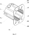
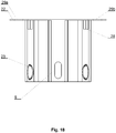
- Fig. 17-18 depict the body 2 of the flush-mounted junction box as in embodiments 1 to 3, in which the female dovetail 26 and the male dovetail 27 have coaxial pass-through openings 6. After the bodies 2 have been joined together, the coaxial pass-through openings 6 allow to easily run cables between them.
- Fig. 19 depicts the body 2 of the flush-mounted junction box as in embodiments 1 to 4, in which the supporting flange 22 additionally has the first pour-in opening 29a and the second pour-in opening 29b , wherein the second pour-in opening 29b is filled with a removable plug.
- the first pour-in opening 29a and the second pour-in opening 29b are located on opposite sections of the supporting flange 22 along a single axis of symmetry.
- the pour-in openings 29a and 29b allow to introduce glue mass in order to permanently embed the body 2 of the flush-mounted junction box 1 in the wall.
- the first pour-in opening 29a also indicates the part of the flush-mounted junction box 1 that should be on top after installation.
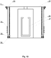
- Fig. 20 depicts the body 2 of the flush-mounted junction box 1 as in embodiments 1 to 5, in which the supporting flange 22 has two pairs of opposite openings 71 designed to receive wedges 8 during the provisional insertion of the body 2 in the wall. On the external surface of the body 2 there are also bases 28 that are aligned with the openings 71 (as shown in Fig. 20 ). The pairs of opposite openings 71 are located on the diagonals of the supporting flange 22.
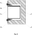
- Fig. 21 depicts the body 2 provisionally placed in the wall using wedges 8 inserted into the openings 71.
- the body 2 of the junction box 1 is inserted into a recess in the masonry wall 5, and then the wedges 8 are inserted into the openings 71 so that they rest against the base 28 and the masonry wall 5 thus forming a rigid connection.
- glue mass can be introduced into the first pour-in opening 29a and/or the second pour-in opening 29b in order to permanently embed the body 2 in the masonry wall 5.
Landscapes
- Engineering & Computer Science (AREA)
- Architecture (AREA)
- Civil Engineering (AREA)
- Structural Engineering (AREA)
- Connection Or Junction Boxes (AREA)
- Patch Boards (AREA)
- Sanitary Device For Flush Toilet (AREA)
Applications Claiming Priority (1)
| Application Number | Priority Date | Filing Date | Title |
|---|---|---|---|
| PL429038A PL237388B1 (pl) | 2019-02-26 | 2019-02-26 | Podtynkowa puszka instalacyjna |
Publications (2)
| Publication Number | Publication Date |
|---|---|
| EP3703207A1 true EP3703207A1 (fr) | 2020-09-02 |
| EP3703207B1 EP3703207B1 (fr) | 2022-09-21 |
Family
ID=70333763
Family Applications (1)
| Application Number | Title | Priority Date | Filing Date |
|---|---|---|---|
| EP20159652.5A Active EP3703207B1 (fr) | 2019-02-26 | 2020-02-26 | Boîte de raccordement encastrée |
Country Status (2)
| Country | Link |
|---|---|
| EP (1) | EP3703207B1 (fr) |
| PL (1) | PL237388B1 (fr) |
Cited By (2)
| Publication number | Priority date | Publication date | Assignee | Title |
|---|---|---|---|---|
| CN112952730A (zh) * | 2021-01-21 | 2021-06-11 | 武汉船用机械有限责任公司 | 接线盒 |
| US11557888B2 (en) | 2019-02-14 | 2023-01-17 | Erico International Corporation | Adjustable depth electrical wall mount ring |
Citations (8)
| Publication number | Priority date | Publication date | Assignee | Title |
|---|---|---|---|---|
| US5783774A (en) * | 1996-10-21 | 1998-07-21 | Walker Systems, Inc. | Non-metallic floor box |
| FR2868618A1 (fr) * | 2004-03-30 | 2005-10-07 | Capri Codec Sas Soc Par Action | Ensemble reglable indexable en plastique de maintien d'elements tels que des boitiers d'appareillage electrique entre des banches |
| CN204578020U (zh) | 2015-03-11 | 2015-08-19 | 中铁上海工程局集团有限公司 | 一种可调节型墙体预埋接线盒 |
| CN204732809U (zh) | 2015-06-09 | 2015-10-28 | 张少伟 | 一种电器接线盒 |
| CN105391009A (zh) | 2015-12-08 | 2016-03-09 | 王明烁 | 一种可伸缩便于安装的86底盒 |
| CN105896424A (zh) | 2016-05-31 | 2016-08-24 | 福建西河卫浴科技有限公司 | 一种预埋盒安装调节结构 |
| US20160352087A1 (en) * | 2015-06-01 | 2016-12-01 | Hubbell Incorporated | Adjustable floor box |
| CN206585291U (zh) | 2017-03-24 | 2017-10-24 | 业之峰诺华家居装饰集团股份有限公司 | 可拉长的防尘接线暗盒 |
-
2019
- 2019-02-26 PL PL429038A patent/PL237388B1/pl unknown
-
2020
- 2020-02-26 EP EP20159652.5A patent/EP3703207B1/fr active Active
Patent Citations (8)
| Publication number | Priority date | Publication date | Assignee | Title |
|---|---|---|---|---|
| US5783774A (en) * | 1996-10-21 | 1998-07-21 | Walker Systems, Inc. | Non-metallic floor box |
| FR2868618A1 (fr) * | 2004-03-30 | 2005-10-07 | Capri Codec Sas Soc Par Action | Ensemble reglable indexable en plastique de maintien d'elements tels que des boitiers d'appareillage electrique entre des banches |
| CN204578020U (zh) | 2015-03-11 | 2015-08-19 | 中铁上海工程局集团有限公司 | 一种可调节型墙体预埋接线盒 |
| US20160352087A1 (en) * | 2015-06-01 | 2016-12-01 | Hubbell Incorporated | Adjustable floor box |
| CN204732809U (zh) | 2015-06-09 | 2015-10-28 | 张少伟 | 一种电器接线盒 |
| CN105391009A (zh) | 2015-12-08 | 2016-03-09 | 王明烁 | 一种可伸缩便于安装的86底盒 |
| CN105896424A (zh) | 2016-05-31 | 2016-08-24 | 福建西河卫浴科技有限公司 | 一种预埋盒安装调节结构 |
| CN206585291U (zh) | 2017-03-24 | 2017-10-24 | 业之峰诺华家居装饰集团股份有限公司 | 可拉长的防尘接线暗盒 |
Cited By (2)
| Publication number | Priority date | Publication date | Assignee | Title |
|---|---|---|---|---|
| US11557888B2 (en) | 2019-02-14 | 2023-01-17 | Erico International Corporation | Adjustable depth electrical wall mount ring |
| CN112952730A (zh) * | 2021-01-21 | 2021-06-11 | 武汉船用机械有限责任公司 | 接线盒 |
Also Published As
| Publication number | Publication date |
|---|---|
| EP3703207B1 (fr) | 2022-09-21 |
| PL237388B1 (pl) | 2021-04-06 |
| PL429038A1 (pl) | 2020-09-07 |
Similar Documents
| Publication | Publication Date | Title |
|---|---|---|
| EP3703207A1 (fr) | Boîte de raccordement encastrée | |
| KR100674253B1 (ko) | 배전선로 내 애자의 위치 변경이 용이한 단일형 내장 완철조립체. | |
| US10148046B2 (en) | Holding frame for plug connector modules | |
| US20200227901A9 (en) | Networking enclosure assembly with magnetic alignment and interlocking, adaptable to be installed in different locations and positions | |
| JP4436867B2 (ja) | ブスバー組付け装置 | |
| US9787073B1 (en) | ICF electrical box | |
| KR20100106367A (ko) | 연결 피팅 및 설치 장치 | |
| WO2015053643A2 (fr) | Barre canal multi-élément | |
| CN215908828U (zh) | 一种一体机及其壁挂结构 | |
| BR112019014298A2 (pt) | Conjunto de fixação, e, método de utilização de um conjunto de fixação. | |
| EP2270941B1 (fr) | Ensemble de bouton-pression pour accessoire encastré | |
| KR102530661B1 (ko) | 높낮이 조절이 가능한 전기 및 통신 배선박스 | |
| US20160053478A1 (en) | Interlocking Clip System | |
| US9368949B2 (en) | Channel system | |
| JP2000509561A (ja) | 組付けレールを有する組付けユニット | |
| AU2018100721A4 (en) | Cable Junction | |
| RU2707222C2 (ru) | Соединительный элемент для механического соединения рам распределительных устройств | |
| CN209384446U (zh) | 墙板的镶嵌式连接结构 | |
| CN216530812U (zh) | 一种装配稳固的马达支架 | |
| FI106755B (fi) | Sovitelma pistoliittimen kiinnittämiseksi ja pistoliitin | |
| KR200452701Y1 (ko) | 케이블 접속모듈 | |
| AU2012202732B2 (en) | A Backing Plate and Wiring Housing Unit | |
| CN211472629U (zh) | 斗杆 | |
| JPS6224949Y2 (fr) | ||
| WO2016198696A2 (fr) | Boîtier arrière électrique destiné à être monté à l'intérieur d'un trou sensiblement circulaire |
Legal Events
| Date | Code | Title | Description |
|---|---|---|---|
| PUAI | Public reference made under article 153(3) epc to a published international application that has entered the european phase |
Free format text: ORIGINAL CODE: 0009012 |
|
| STAA | Information on the status of an ep patent application or granted ep patent |
Free format text: STATUS: THE APPLICATION HAS BEEN PUBLISHED |
|
| AK | Designated contracting states |
Kind code of ref document: A1 Designated state(s): AL AT BE BG CH CY CZ DE DK EE ES FI FR GB GR HR HU IE IS IT LI LT LU LV MC MK MT NL NO PL PT RO RS SE SI SK SM TR |
|
| AX | Request for extension of the european patent |
Extension state: BA ME |
|
| STAA | Information on the status of an ep patent application or granted ep patent |
Free format text: STATUS: REQUEST FOR EXAMINATION WAS MADE |
|
| RBV | Designated contracting states (corrected) |
Designated state(s): AL AT BE BG CH CY CZ DE DK EE ES FI FR GB GR HR HU IE IS IT LI LT LU LV MC MK MT NL NO PL PT RO RS SE SI SK SM TR |
|
| 17P | Request for examination filed |
Effective date: 20210210 |
|
| GRAP | Despatch of communication of intention to grant a patent |
Free format text: ORIGINAL CODE: EPIDOSNIGR1 |
|
| STAA | Information on the status of an ep patent application or granted ep patent |
Free format text: STATUS: GRANT OF PATENT IS INTENDED |
|
| INTG | Intention to grant announced |
Effective date: 20211015 |
|
| RIN1 | Information on inventor provided before grant (corrected) |
Inventor name: DUDEK, KRZYSZTOF |
|
| GRAS | Grant fee paid |
Free format text: ORIGINAL CODE: EPIDOSNIGR3 |
|
| GRAJ | Information related to disapproval of communication of intention to grant by the applicant or resumption of examination proceedings by the epo deleted |
Free format text: ORIGINAL CODE: EPIDOSDIGR1 |
|
| GRAL | Information related to payment of fee for publishing/printing deleted |
Free format text: ORIGINAL CODE: EPIDOSDIGR3 |
|
| STAA | Information on the status of an ep patent application or granted ep patent |
Free format text: STATUS: REQUEST FOR EXAMINATION WAS MADE |
|
| INTC | Intention to grant announced (deleted) | ||
| GRAP | Despatch of communication of intention to grant a patent |
Free format text: ORIGINAL CODE: EPIDOSNIGR1 |
|
| STAA | Information on the status of an ep patent application or granted ep patent |
Free format text: STATUS: GRANT OF PATENT IS INTENDED |
|
| GRAS | Grant fee paid |
Free format text: ORIGINAL CODE: EPIDOSNIGR3 |
|
| INTG | Intention to grant announced |
Effective date: 20220412 |
|
| GRAA | (expected) grant |
Free format text: ORIGINAL CODE: 0009210 |
|
| STAA | Information on the status of an ep patent application or granted ep patent |
Free format text: STATUS: THE PATENT HAS BEEN GRANTED |
|
| AK | Designated contracting states |
Kind code of ref document: B1 Designated state(s): AL AT BE BG CH CY CZ DE DK EE ES FI FR GB GR HR HU IE IS IT LI LT LU LV MC MK MT NL NO PL PT RO RS SE SI SK SM TR |
|
| REG | Reference to a national code |
Ref country code: GB Ref legal event code: FG4D |
|
| REG | Reference to a national code |
Ref country code: CH Ref legal event code: EP |
|
| REG | Reference to a national code |
Ref country code: IE Ref legal event code: FG4D |
|
| REG | Reference to a national code |
Ref country code: DE Ref legal event code: R096 Ref document number: 602020005192 Country of ref document: DE |
|
| REG | Reference to a national code |
Ref country code: AT Ref legal event code: REF Ref document number: 1520442 Country of ref document: AT Kind code of ref document: T Effective date: 20221015 |
|
| REG | Reference to a national code |
Ref country code: LT Ref legal event code: MG9D |
|
| REG | Reference to a national code |
Ref country code: NL Ref legal event code: MP Effective date: 20220921 |
|
| PG25 | Lapsed in a contracting state [announced via postgrant information from national office to epo] |
Ref country code: SE Free format text: LAPSE BECAUSE OF FAILURE TO SUBMIT A TRANSLATION OF THE DESCRIPTION OR TO PAY THE FEE WITHIN THE PRESCRIBED TIME-LIMIT Effective date: 20220921 Ref country code: RS Free format text: LAPSE BECAUSE OF FAILURE TO SUBMIT A TRANSLATION OF THE DESCRIPTION OR TO PAY THE FEE WITHIN THE PRESCRIBED TIME-LIMIT Effective date: 20220921 Ref country code: NO Free format text: LAPSE BECAUSE OF FAILURE TO SUBMIT A TRANSLATION OF THE DESCRIPTION OR TO PAY THE FEE WITHIN THE PRESCRIBED TIME-LIMIT Effective date: 20221221 Ref country code: LV Free format text: LAPSE BECAUSE OF FAILURE TO SUBMIT A TRANSLATION OF THE DESCRIPTION OR TO PAY THE FEE WITHIN THE PRESCRIBED TIME-LIMIT Effective date: 20220921 Ref country code: LT Free format text: LAPSE BECAUSE OF FAILURE TO SUBMIT A TRANSLATION OF THE DESCRIPTION OR TO PAY THE FEE WITHIN THE PRESCRIBED TIME-LIMIT Effective date: 20220921 Ref country code: FI Free format text: LAPSE BECAUSE OF FAILURE TO SUBMIT A TRANSLATION OF THE DESCRIPTION OR TO PAY THE FEE WITHIN THE PRESCRIBED TIME-LIMIT Effective date: 20220921 |
|
| REG | Reference to a national code |
Ref country code: AT Ref legal event code: MK05 Ref document number: 1520442 Country of ref document: AT Kind code of ref document: T Effective date: 20220921 |
|
| PG25 | Lapsed in a contracting state [announced via postgrant information from national office to epo] |
Ref country code: HR Free format text: LAPSE BECAUSE OF FAILURE TO SUBMIT A TRANSLATION OF THE DESCRIPTION OR TO PAY THE FEE WITHIN THE PRESCRIBED TIME-LIMIT Effective date: 20220921 Ref country code: GR Free format text: LAPSE BECAUSE OF FAILURE TO SUBMIT A TRANSLATION OF THE DESCRIPTION OR TO PAY THE FEE WITHIN THE PRESCRIBED TIME-LIMIT Effective date: 20221222 |
|
| PG25 | Lapsed in a contracting state [announced via postgrant information from national office to epo] |
Ref country code: SM Free format text: LAPSE BECAUSE OF FAILURE TO SUBMIT A TRANSLATION OF THE DESCRIPTION OR TO PAY THE FEE WITHIN THE PRESCRIBED TIME-LIMIT Effective date: 20220921 Ref country code: RO Free format text: LAPSE BECAUSE OF FAILURE TO SUBMIT A TRANSLATION OF THE DESCRIPTION OR TO PAY THE FEE WITHIN THE PRESCRIBED TIME-LIMIT Effective date: 20220921 Ref country code: PT Free format text: LAPSE BECAUSE OF FAILURE TO SUBMIT A TRANSLATION OF THE DESCRIPTION OR TO PAY THE FEE WITHIN THE PRESCRIBED TIME-LIMIT Effective date: 20230123 Ref country code: ES Free format text: LAPSE BECAUSE OF FAILURE TO SUBMIT A TRANSLATION OF THE DESCRIPTION OR TO PAY THE FEE WITHIN THE PRESCRIBED TIME-LIMIT Effective date: 20220921 Ref country code: CZ Free format text: LAPSE BECAUSE OF FAILURE TO SUBMIT A TRANSLATION OF THE DESCRIPTION OR TO PAY THE FEE WITHIN THE PRESCRIBED TIME-LIMIT Effective date: 20220921 Ref country code: AT Free format text: LAPSE BECAUSE OF FAILURE TO SUBMIT A TRANSLATION OF THE DESCRIPTION OR TO PAY THE FEE WITHIN THE PRESCRIBED TIME-LIMIT Effective date: 20220921 |
|
| PG25 | Lapsed in a contracting state [announced via postgrant information from national office to epo] |
Ref country code: SK Free format text: LAPSE BECAUSE OF FAILURE TO SUBMIT A TRANSLATION OF THE DESCRIPTION OR TO PAY THE FEE WITHIN THE PRESCRIBED TIME-LIMIT Effective date: 20220921 Ref country code: PL Free format text: LAPSE BECAUSE OF FAILURE TO SUBMIT A TRANSLATION OF THE DESCRIPTION OR TO PAY THE FEE WITHIN THE PRESCRIBED TIME-LIMIT Effective date: 20220921 Ref country code: IS Free format text: LAPSE BECAUSE OF FAILURE TO SUBMIT A TRANSLATION OF THE DESCRIPTION OR TO PAY THE FEE WITHIN THE PRESCRIBED TIME-LIMIT Effective date: 20230121 Ref country code: EE Free format text: LAPSE BECAUSE OF FAILURE TO SUBMIT A TRANSLATION OF THE DESCRIPTION OR TO PAY THE FEE WITHIN THE PRESCRIBED TIME-LIMIT Effective date: 20220921 |
|
| REG | Reference to a national code |
Ref country code: DE Ref legal event code: R097 Ref document number: 602020005192 Country of ref document: DE |
|
| PG25 | Lapsed in a contracting state [announced via postgrant information from national office to epo] |
Ref country code: NL Free format text: LAPSE BECAUSE OF FAILURE TO SUBMIT A TRANSLATION OF THE DESCRIPTION OR TO PAY THE FEE WITHIN THE PRESCRIBED TIME-LIMIT Effective date: 20220921 Ref country code: AL Free format text: LAPSE BECAUSE OF FAILURE TO SUBMIT A TRANSLATION OF THE DESCRIPTION OR TO PAY THE FEE WITHIN THE PRESCRIBED TIME-LIMIT Effective date: 20220921 |
|
| PLBE | No opposition filed within time limit |
Free format text: ORIGINAL CODE: 0009261 |
|
| STAA | Information on the status of an ep patent application or granted ep patent |
Free format text: STATUS: NO OPPOSITION FILED WITHIN TIME LIMIT |
|
| PG25 | Lapsed in a contracting state [announced via postgrant information from national office to epo] |
Ref country code: DK Free format text: LAPSE BECAUSE OF FAILURE TO SUBMIT A TRANSLATION OF THE DESCRIPTION OR TO PAY THE FEE WITHIN THE PRESCRIBED TIME-LIMIT Effective date: 20220921 |
|
| 26N | No opposition filed |
Effective date: 20230622 |
|
| PG25 | Lapsed in a contracting state [announced via postgrant information from national office to epo] |
Ref country code: SI Free format text: LAPSE BECAUSE OF FAILURE TO SUBMIT A TRANSLATION OF THE DESCRIPTION OR TO PAY THE FEE WITHIN THE PRESCRIBED TIME-LIMIT Effective date: 20220921 |
|
| PG25 | Lapsed in a contracting state [announced via postgrant information from national office to epo] |
Ref country code: MC Free format text: LAPSE BECAUSE OF FAILURE TO SUBMIT A TRANSLATION OF THE DESCRIPTION OR TO PAY THE FEE WITHIN THE PRESCRIBED TIME-LIMIT Effective date: 20220921 |
|
| REG | Reference to a national code |
Ref country code: CH Ref legal event code: PL |
|
| REG | Reference to a national code |
Ref country code: BE Ref legal event code: MM Effective date: 20230228 |
|
| PG25 | Lapsed in a contracting state [announced via postgrant information from national office to epo] |
Ref country code: LU Free format text: LAPSE BECAUSE OF NON-PAYMENT OF DUE FEES Effective date: 20230226 Ref country code: LI Free format text: LAPSE BECAUSE OF NON-PAYMENT OF DUE FEES Effective date: 20230228 Ref country code: CH Free format text: LAPSE BECAUSE OF NON-PAYMENT OF DUE FEES Effective date: 20230228 |
|
| REG | Reference to a national code |
Ref country code: IE Ref legal event code: MM4A |
|
| PG25 | Lapsed in a contracting state [announced via postgrant information from national office to epo] |
Ref country code: IE Free format text: LAPSE BECAUSE OF NON-PAYMENT OF DUE FEES Effective date: 20230226 Ref country code: FR Free format text: LAPSE BECAUSE OF NON-PAYMENT OF DUE FEES Effective date: 20230228 |
|
| PG25 | Lapsed in a contracting state [announced via postgrant information from national office to epo] |
Ref country code: BE Free format text: LAPSE BECAUSE OF NON-PAYMENT OF DUE FEES Effective date: 20230228 |
|
| PGFP | Annual fee paid to national office [announced via postgrant information from national office to epo] |
Ref country code: DE Payment date: 20240122 Year of fee payment: 5 |