EP3703152A1 - Battery module - Google Patents
Battery module Download PDFInfo
- Publication number
- EP3703152A1 EP3703152A1 EP19191417.5A EP19191417A EP3703152A1 EP 3703152 A1 EP3703152 A1 EP 3703152A1 EP 19191417 A EP19191417 A EP 19191417A EP 3703152 A1 EP3703152 A1 EP 3703152A1
- Authority
- EP
- European Patent Office
- Prior art keywords
- end plate
- insulation component
- heat insulation
- mounting hole
- mounting
- Prior art date
- Legal status (The legal status is an assumption and is not a legal conclusion. Google has not performed a legal analysis and makes no representation as to the accuracy of the status listed.)
- Granted
Links
Images




Classifications
-
- H—ELECTRICITY
- H01—ELECTRIC ELEMENTS
- H01M—PROCESSES OR MEANS, e.g. BATTERIES, FOR THE DIRECT CONVERSION OF CHEMICAL ENERGY INTO ELECTRICAL ENERGY
- H01M50/00—Constructional details or processes of manufacture of the non-active parts of electrochemical cells other than fuel cells, e.g. hybrid cells
- H01M50/20—Mountings; Secondary casings or frames; Racks, modules or packs; Suspension devices; Shock absorbers; Transport or carrying devices; Holders
- H01M50/233—Mountings; Secondary casings or frames; Racks, modules or packs; Suspension devices; Shock absorbers; Transport or carrying devices; Holders characterised by physical properties of casings or racks, e.g. dimensions
- H01M50/24—Mountings; Secondary casings or frames; Racks, modules or packs; Suspension devices; Shock absorbers; Transport or carrying devices; Holders characterised by physical properties of casings or racks, e.g. dimensions adapted for protecting batteries from their environment, e.g. from corrosion
-
- H—ELECTRICITY
- H01—ELECTRIC ELEMENTS
- H01M—PROCESSES OR MEANS, e.g. BATTERIES, FOR THE DIRECT CONVERSION OF CHEMICAL ENERGY INTO ELECTRICAL ENERGY
- H01M50/00—Constructional details or processes of manufacture of the non-active parts of electrochemical cells other than fuel cells, e.g. hybrid cells
- H01M50/50—Current conducting connections for cells or batteries
- H01M50/531—Electrode connections inside a battery casing
- H01M50/54—Connection of several leads or tabs of plate-like electrode stacks, e.g. electrode pole straps or bridges
-
- H—ELECTRICITY
- H01—ELECTRIC ELEMENTS
- H01M—PROCESSES OR MEANS, e.g. BATTERIES, FOR THE DIRECT CONVERSION OF CHEMICAL ENERGY INTO ELECTRICAL ENERGY
- H01M10/00—Secondary cells; Manufacture thereof
- H01M10/04—Construction or manufacture in general
- H01M10/0481—Compression means other than compression means for stacks of electrodes and separators
-
- H—ELECTRICITY
- H01—ELECTRIC ELEMENTS
- H01M—PROCESSES OR MEANS, e.g. BATTERIES, FOR THE DIRECT CONVERSION OF CHEMICAL ENERGY INTO ELECTRICAL ENERGY
- H01M10/00—Secondary cells; Manufacture thereof
- H01M10/60—Heating or cooling; Temperature control
- H01M10/65—Means for temperature control structurally associated with the cells
- H01M10/655—Solid structures for heat exchange or heat conduction
- H01M10/6554—Rods or plates
-
- H—ELECTRICITY
- H01—ELECTRIC ELEMENTS
- H01M—PROCESSES OR MEANS, e.g. BATTERIES, FOR THE DIRECT CONVERSION OF CHEMICAL ENERGY INTO ELECTRICAL ENERGY
- H01M10/00—Secondary cells; Manufacture thereof
- H01M10/60—Heating or cooling; Temperature control
- H01M10/65—Means for temperature control structurally associated with the cells
- H01M10/659—Means for temperature control structurally associated with the cells by heat storage or buffering, e.g. heat capacity or liquid-solid phase changes or transition
-
- H—ELECTRICITY
- H01—ELECTRIC ELEMENTS
- H01M—PROCESSES OR MEANS, e.g. BATTERIES, FOR THE DIRECT CONVERSION OF CHEMICAL ENERGY INTO ELECTRICAL ENERGY
- H01M50/00—Constructional details or processes of manufacture of the non-active parts of electrochemical cells other than fuel cells, e.g. hybrid cells
- H01M50/20—Mountings; Secondary casings or frames; Racks, modules or packs; Suspension devices; Shock absorbers; Transport or carrying devices; Holders
- H01M50/204—Racks, modules or packs for multiple batteries or multiple cells
- H01M50/207—Racks, modules or packs for multiple batteries or multiple cells characterised by their shape
- H01M50/209—Racks, modules or packs for multiple batteries or multiple cells characterised by their shape adapted for prismatic or rectangular cells
-
- Y—GENERAL TAGGING OF NEW TECHNOLOGICAL DEVELOPMENTS; GENERAL TAGGING OF CROSS-SECTIONAL TECHNOLOGIES SPANNING OVER SEVERAL SECTIONS OF THE IPC; TECHNICAL SUBJECTS COVERED BY FORMER USPC CROSS-REFERENCE ART COLLECTIONS [XRACs] AND DIGESTS
- Y02—TECHNOLOGIES OR APPLICATIONS FOR MITIGATION OR ADAPTATION AGAINST CLIMATE CHANGE
- Y02E—REDUCTION OF GREENHOUSE GAS [GHG] EMISSIONS, RELATED TO ENERGY GENERATION, TRANSMISSION OR DISTRIBUTION
- Y02E60/00—Enabling technologies; Technologies with a potential or indirect contribution to GHG emissions mitigation
- Y02E60/10—Energy storage using batteries
-
- Y—GENERAL TAGGING OF NEW TECHNOLOGICAL DEVELOPMENTS; GENERAL TAGGING OF CROSS-SECTIONAL TECHNOLOGIES SPANNING OVER SEVERAL SECTIONS OF THE IPC; TECHNICAL SUBJECTS COVERED BY FORMER USPC CROSS-REFERENCE ART COLLECTIONS [XRACs] AND DIGESTS
- Y02—TECHNOLOGIES OR APPLICATIONS FOR MITIGATION OR ADAPTATION AGAINST CLIMATE CHANGE
- Y02P—CLIMATE CHANGE MITIGATION TECHNOLOGIES IN THE PRODUCTION OR PROCESSING OF GOODS
- Y02P70/00—Climate change mitigation technologies in the production process for final industrial or consumer products
- Y02P70/50—Manufacturing or production processes characterised by the final manufactured product
Definitions
- the present disclosure relates to the technical field of energy storage, and in particular, to a battery module.
- a battery module includes a plurality of batteries, end plates disposed at two ends of the plurality of batteries, and side plates disposed on two sides of the plurality of batteries.
- the end plates are fixedly connected to the side plates to clamp the batteries.
- the batteries should be thermally insulated from the external environment.
- the end plates of the battery module are made of metal, and thus have a high thermal conductivity, such that the batteries close to the end plates have a higher rate of heat transfer, which would result in a poor temperature uniformity of the batteries.
- the present disclosure provides a battery module, aiming to solve the problem of the poor temperature uniformity of the batteries and the short service life of the battery module.
- the present disclosure provides a battery module, including: a plurality of batteries that is stacked; an end plate disposed at an end of the plurality of batteries in a direction, along which the plurality of batteries are stacked; an electric insulation component disposed between the end plate and a battery of the plurality of batteries adjacent to the end plate, the electric insulation component including at least one mounting portion; and at least one heat insulation component disposed below the end plate and connected to a bottom of the end plate.
- Each of the at least one heat insulation component is detachably connected to a corresponding one of the at least one mounting portion.
- the electric insulation component further includes an insulation body disposed between the end plate and the battery adjacent to the end plate.
- the at least one mounting portion is disposed below the end plate, and the at least one mounting portion is connected to the insulation body and extends towards the end plate.
- Each of the at least one mounting portion is provided with a first mounting hole, in which a corresponding one of the at least one heat insulation component is mounted through interference fit.
- each of the at least one heat insulation component is provided with at least one dismounting hole.
- each of the at least one heat insulation component includes two ends each provided with a recess, the recess and a side wall of the first mounting hole define a dismounting hole.
- the electric insulation component further includes an insulation body disposed between the end plate and the battery adjacent to the end plate.
- the at least one mounting portion is disposed below the end plate, and the at least one mounting portion is connected to the insulation body and extends towards the end plate.
- Each of the at least one mounting portion is provided with a first mounting hole, the first mounting hole is a threaded hole, each of the at least one heat insulation component is provided with threads on its periphery, and is connected to the first mounting hole through the threads.
- each of the at least one heat insulation component is further provided with a second mounting hole
- the end plate is provided with an end plate mounting hole.
- the second mounting hole and the end plate mounting hole are coaxial.
- the battery module further includes a fastener penetrating through the second mounting hole and the end plate mounting hole and connecting the end plate with the at least one heat insulation component.
- each of the at least one heat insulation component includes a connecting post
- the end plate includes an end plate mounting hole
- the connecting post is inserted into the end plate mounting hole to connect the at least one heat insulation component with the end plate.
- each of the at least one mounting portion includes a mounting plate provided with the first mounting hole, and reinforcing plates provided at two sides of the mounting plate. The mounting plate and the reinforcing plates are connected to the insulation body.
- each of the at least one heat insulation component includes a thickness greater than a depth of the first mounting hole.
- Each of the at least one heat insulation component includes an upper end surface protruding from an upper surface of the mounting plate by 0mm to 2mm, and a lower end surface protruding from a lower surface of the mounting plate by 0mm to 2mm.
- each of the at least one heat insulation component is made of epoxy resin, plastic, or ceramic.
- the bottom of the end plate of the battery module is connected to the heat insulation component, so that the end plate and other components located at the bottom thereof are separated by the heat insulation component, and the heat conduction efficiency of the end plate is lowered, thereby improving the temperature uniformity of the batteries of the battery module.
- the heat insulation component is detachably connected to the mounting portion of the electric insulation component, the damaged heat insulation component can be dismounted from the mounting portion and replaced, thereby prolonging the service life of the battery module.
- orientations or positions such as “upper”, “lower”, “left”, “right”, etc., generally are used to describe the orientations or positions with reference to the drawings, and thus should not be construed as a limitation of the present disclosure. It also should be understood that when an element is referred as being “on” or “under” another element, the element can be directly located “on” or “under” another element or connected to another element with an intermediate element.
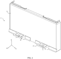
- FIG. 1 is an exploded view of a battery module according to an embodiment of the present disclosure
- FIG. 2 is an exploded view of FIG. 1
- FIG. 3 is a structural schematic diagram illustrating that an electric insulation component is matched with a heat insulation component shown in FIG. 1
- FIG. 4 is an exploded view of FIG. 3
- FIG. 5 is a front view of FIG. 3
- FIG. 6 is a top view of FIG. 3
- FIG. 7 is a cross-sectional view along A-A in FIG. 6 .
- the present disclosure provides a battery module.
- the battery module includes a plurality of batteries 5 that is stacked, and end plates 1 disposed at ends of the plurality of batteries 5 along a direction, in which the batteries are stacked (a direction X as shown in FIG. 1 ).
- Two end plates 1 are provided and arranged opposite to each other in the direction X.
- An electric insulation component 3 is provided between the end plate 1 and a battery 5 adjacent to the end plate 1.
- the battery module further includes two side plates 2 disposed opposite to each other in a direction Y. Once the end plates 1 and the side plates 2 are fixed by laser welding, the electric insulation component 3 and the batteries 5 can be clamped to form the battery module shown in FIG. 1 .
- the electric insulation component 3 is located between the end plate 1 and the battery 5 adjacent to the end plate 1, for insulating the end plate 1 from the battery 5 adjacent to the end plate 1.
- the electric insulation component 3 has good properties of both heat insulation and electric insulation, and thus can be used as a thermally and electrically insulating structure between the end plate 1 and the battery 5 adjacent to the end plate 1.
- the electric insulation component 3 is clamped between the end plate 1 and the battery 5 adjacent to the end plate 1, and can provide an end surface of the end plate 1 with good heat insulation.
- a bottom of the end plate 1 is in contact with other metal structures, such as a mounting seat of a battery pack or the like, resulting in the problem of the temperature non-uniformity of batteries 5 caused by heat conduction from the bottom of the end plate 1.
- the end plate 1 is provided with at least one heat insulation component 4 at its bottom, so as to separate the end plate 1 from the other metal structures by the heat insulation component 4.
- the bottom of the end plate 1 has a reduced heat conduction efficiency, and the temperature uniformity of the battery 5 is improved.
- the heat insulation component 4 disposed at the bottom of the end plate 1 is easily damaged. Therefore, in order to ensure that the battery module 5 can have a good temperature uniformity during a long-term operation, the damaged heat insulation component 4 is required to be replaced timely.
- the heat insulation component 4 is mounted on the electric insulation component 3.
- the present disclosure adopts a structure as shown in FIG. 3 , in which at least one mounting portion 32 is provided at the bottom of the electric insulation component 3, and the heat insulation component 4 is detachably connected to a corresponding mounting portion 32, while the bottom of the end plate 1 is connected to the heat insulation component 4.
- the bottom of the end plate 1 of the battery module is connected to the heat insulation component 4, so that the end plate 1 and other components located at the bottom thereof are separated by the heat insulation component 4, thereby lowering the heat conduction efficiency of the end plate 1 and improving the temperature uniformity of the batteries 5 of the battery module.
- the heat insulation component 4 since the heat insulation component 4 is detachably connected to the mounting portion 32, the heat insulation component 4, when being damaged, can be dismounted from the mounting portion 32 and replaced, thereby prolonging the service life of the battery module.
- the electric insulation component 3 includes an insulation body 31, and the insulation body 31 is located between the end plate 1 and the battery 5 adjacent to the end plate 1.
- the insulation body 31 is used for the thermal and electrical insulation between an end surface of the end plate 1 and the battery 5 adjacent to the end plate 1.
- the insertion body 31 has at least one mounting portion 32 at its bottom.
- the mounting portion 32 is located below the end plate 1.
- the mounting portion 32 is fixedly connected to the insulation body 31, and the mounting portion 32 extends in a direction facing towards the end plate 1, i.e., the mounting portion 32 extends in the direction X.
- the mounting portion 32 is provided with a first mounting hole 321a matched with the heat insulation component 4, and the heat insulation component 4 is mounted in the first mounting hole 321a through interference fit.
- the heat insulation component 4 is connected to the mounting portion 32 by pressing the heat insulation component 4 to the first mounting hole 321a through interference fit. Meanwhile, as shown in FIG. 3 , the heat insulation component 4 is provided with at least one dismounting hole 41, and the heat insulation component 3 can be easily removed from the first mounting hole 321a by means of the dismounting hole 41.
- the heat insulation component 4 is in a plate-like structure, and has two opposite ends each provided with a recess 411.
- a side wall of the recess 411 and a side wall of the first mounting hole 321a define a dismounting hole 41.
- the dismounting hole 41 can have a shape of circle, semicircle, arc, rectangle, triangle, polygon, or the like.
- the heat insulation component 4 has two opposite dismounting holes 41, and the dismounting holes 41 are configured to receive a dismounting tool.
- the dismounting tool can be a columnar structure having a size slightly larger than the dismounting hole 41.
- the disassembly tool when the heat insulation component 4 has two dismounting holes 41, the disassembly tool also can be a clamp.
- the clamp has two legs each protruding into a corresponding dismounting hole 41, and pulls the heat insulation component 4 out of the first mounting hole 321a.
- liquid nitrogen cooling can be employed to cause a contraction of the heat insulation component 4, which can facilitate removing from the first mounting hole 321a.
- the recess 411 is a semi-circular structure and has a diameter of 4 mm to 6 mm, preferably 5 mm.
- the shape and size of the recess 411 are not limited thereto, and the recess 411 also can be a square hole, a trapezoidal hole, a triangular hole or the like.
- two recesses 411 can also be provided at two ends of the heat insulation component 4 along the direction X, instead of being provided at the two ends of the heat insulation component 4 along the direction Y.
- the heat insulation component 4 has sufficient space at two ends in the direction Y, it is conducive to the dismounting of the heat insulation component 4 to provide the two recesses 411 at the ends along the direction Y.
- the mounting and dismounting manner between the heat insulation component 4 and the first mounting hole 321a is not limited to the interference pressing fit.
- the heat insulation component 4 can also be provided with external threads, and the first mounting hole 321a can be a threaded hole having internal threads, such that the heat insulation component 4 can be detachably connected to the mounting portion 32 through screw-thread fit between the heat insulation component 4 and the first mounting hole 321a.
- the end plate 1 is provided with an end plate mounting hole 11, as shown in FIG. 2 . It can be understood that the end plate mounting hole 11 penetrates the end plate 1 in a direction Z.
- the heat insulation component 4 is further provided with a second mounting hole 42, and the second mounting hole 42 and the end plate mounting hole 11 have a same diameter and are coaxial.
- the battery module can further include a fastener (not shown) such as bolts, screws, etc., such that when the bottom of the end plate 1 abuts against the heat insulation component 4, the fastener passes through the second mounting hole 42 and the end plate mounting hole 11 to connect the end plate 1 with the heat insulation component 4.
- the second mounting hole has a diameter of 6 mm to 10 mm, preferably 8 mm.
- the end plate 1 can be connected to the heat insulation component 4 in the following way.
- the heat insulation component 4 is provided with a connecting post (not shown) at its upper end surface facing towards the end plate 1, the connecting post is matched with the end plate mounting hole 11 of the end plate 1, and the connecting post is inserted into the end plate mounting hole 11 to connect the heat insulation component 4 with the end plate 1.
- the connecting post can also serve as an operating portion during the process of the screw-thread fit of those two, thereby sufficiently utilizing each component.
- the mounting portion 32 includes a mounting plate 321 and reinforcing plates 322.
- the mounting plate 321 has an end surface perpendicular to the direction Z, i.e., the mounting plate 321 is perpendicular to the end plate 1.
- the above first mounting hole 321a is provided in the mounting plate 321.
- the reinforcing plates 322 are disposed on two sides of the mounting plate 321, and the mounting plate 321 and the reinforcing plates 322 are fixedly connected to the insulation body 31.
- the mounting portion 32 can be formed with the insulation body 31 as one piece, or can be a structure to be fixedly connected to the insulation body 31.
- the reinforcing plates 322 can be formed with the mounting plate 321 as one piece, or can be fixedly connected to the mounting plate 321.
- the reinforcing plate 322 in this embodiment has a trapezoidal structure, which has its lower bottom (a bottom surface having the greater length) fixed to the insulation body 31. Since the bottom of the trapezoidal structure has the greater length, a connection area between the reinforcing plates 322 and the insulation body 31 is increased, thereby improving the connection reliability between the mounting portion 32 and the insulation body 31 and enhancing the strength and rigidity of the mounting portion 32 itself.
- the heat insulation component 4 has its upper end surface 43 protruding from an upper surface 321b of the mounting plate 321 and its lower end surface 44 protruding from a lower surface 321c of the mounting plate 321.
- the electric insulation component 3 is made of a material having a relatively low strength, i.e., the strength of the mounting portion 32 is relatively low.
- the mounting portion 32 is not suitable as a main force-receiving component.
- the heat insulation component 4 has a thickness greater than a depth of the first mounting hole 321a. That is, the upper end surface 43 of the heat insulation component 4 protrudes from the upper surface 321b of the mounting plate 321 by a first predetermined size, and the lower end surface 44 protrudes from the lower surface 321c of the mounting plate 321 by a second predetermined size.
- the upper end surface 43 and the lower end surface 44 of the heat insulation component 4 serve as main force-receiving portions, thereby preventing the mounting portion 32 from being damaged when acting as the main force-receiving component.
- the first predetermined size is in a range of 0mm to 2mm, for example, 1mm, 1.5mm, etc.
- the second predetermined size is in a range of 0mm to 2mm, such as 0.8mm, 1.7mm, etc.
- the first predetermined size and the second predetermined size can be equal or unequal, and there is no strict relationship between their sizes.
- the heat insulation component 4 can be made of one or more selected from epoxy resin, plastic, and ceramic.
- the epoxy resin has good thermal and electrical insulation properties and high strength, which can achieve the above-mentioned functions of the heat insulation component 4.
- the heat insulation component 4 can have a structure of a rectangular flat plate and a size of 21 mm ⁇ 14 mm ⁇ 2.5 mm. That is, the epoxy resin plate has a length of 21 mm, a width of 14 mm, and a thickness of 2.5 mm.
- the size of the heat insulation component 4 is not limited thereto, and may be arbitrarily selected according to actual conditions.
- the first mounting hole 321a of the mounting portion 32 is also a rectangular hole.
- the shapes and sizes of the first mounting hole 321a and the heat insulation component 4 are not specifically limited, as long as they can match each other.
- the insulation body 31 is provided with two mounting portions 31 distributed along the direction Y, the battery module accordingly includes two heat insulation components 4, and the two heat insulation components 4 have the same heights in the direction Z.
- the end plate 1 can abut against and be connected to the upper end surfaces 43 of the two heat insulation components 4.
- the number of heat insulation components 4 is not limited in the present disclosure.
Landscapes
- Chemical & Material Sciences (AREA)
- Chemical Kinetics & Catalysis (AREA)
- Electrochemistry (AREA)
- General Chemical & Material Sciences (AREA)
- Engineering & Computer Science (AREA)
- Manufacturing & Machinery (AREA)
- Secondary Cells (AREA)
- Battery Mounting, Suspending (AREA)
Abstract
Description
- The present disclosure relates to the technical field of energy storage, and in particular, to a battery module.
- A battery module includes a plurality of batteries, end plates disposed at two ends of the plurality of batteries, and side plates disposed on two sides of the plurality of batteries. The end plates are fixedly connected to the side plates to clamp the batteries. During the operation of the battery module, it is required to maintain a temperature uniformity of the batteries. Therefore, the batteries should be thermally insulated from the external environment.
- The end plates of the battery module are made of metal, and thus have a high thermal conductivity, such that the batteries close to the end plates have a higher rate of heat transfer, which would result in a poor temperature uniformity of the batteries.
- In view of the above, the present disclosure provides a battery module, aiming to solve the problem of the poor temperature uniformity of the batteries and the short service life of the battery module.
- The present disclosure provides a battery module, including: a plurality of batteries that is stacked; an end plate disposed at an end of the plurality of batteries in a direction, along which the plurality of batteries are stacked; an electric insulation component disposed between the end plate and a battery of the plurality of batteries adjacent to the end plate, the electric insulation component including at least one mounting portion; and at least one heat insulation component disposed below the end plate and connected to a bottom of the end plate. Each of the at least one heat insulation component is detachably connected to a corresponding one of the at least one mounting portion.
- In an embodiment, the electric insulation component further includes an insulation body disposed between the end plate and the battery adjacent to the end plate. The at least one mounting portion is disposed below the end plate, and the at least one mounting portion is connected to the insulation body and extends towards the end plate. Each of the at least one mounting portion is provided with a first mounting hole, in which a corresponding one of the at least one heat insulation component is mounted through interference fit.
- In an embodiment, each of the at least one heat insulation component is provided with at least one dismounting hole.
- In an embodiment, each of the at least one heat insulation component includes two ends each provided with a recess, the recess and a side wall of the first mounting hole define a dismounting hole.
- In an embodiment, the electric insulation component further includes an insulation body disposed between the end plate and the battery adjacent to the end plate. The at least one mounting portion is disposed below the end plate, and the at least one mounting portion is connected to the insulation body and extends towards the end plate. Each of the at least one mounting portion is provided with a first mounting hole, the first mounting hole is a threaded hole, each of the at least one heat insulation component is provided with threads on its periphery, and is connected to the first mounting hole through the threads.
- In an embodiment, each of the at least one heat insulation component is further provided with a second mounting hole, and the end plate is provided with an end plate mounting hole. The second mounting hole and the end plate mounting hole are coaxial. The battery module further includes a fastener penetrating through the second mounting hole and the end plate mounting hole and connecting the end plate with the at least one heat insulation component.
- In an embodiment, each of the at least one heat insulation component includes a connecting post, the end plate includes an end plate mounting hole, and the connecting post is inserted into the end plate mounting hole to connect the at least one heat insulation component with the end plate.
- In an embodiment, each of the at least one mounting portion includes a mounting plate provided with the first mounting hole, and reinforcing plates provided at two sides of the mounting plate. The mounting plate and the reinforcing plates are connected to the insulation body.
- In an embodiment, each of the at least one heat insulation component includes a thickness greater than a depth of the first mounting hole. Each of the at least one heat insulation component includes an upper end surface protruding from an upper surface of the mounting plate by 0mm to 2mm, and a lower end surface protruding from a lower surface of the mounting plate by 0mm to 2mm.
- In an embodiment, each of the at least one heat insulation component is made of epoxy resin, plastic, or ceramic.
- In the present application, the bottom of the end plate of the battery module is connected to the heat insulation component, so that the end plate and other components located at the bottom thereof are separated by the heat insulation component, and the heat conduction efficiency of the end plate is lowered, thereby improving the temperature uniformity of the batteries of the battery module. Moreover, since the heat insulation component is detachably connected to the mounting portion of the electric insulation component, the damaged heat insulation component can be dismounted from the mounting portion and replaced, thereby prolonging the service life of the battery module.
- In order to more clearly illustrate the technical solutions of the embodiments of the present disclosure, the drawings used in the embodiments will be briefly described as below. The drawings described below are merely some embodiments of the present disclosure. Based on these drawings, those skilled in the art can obtain other drawings without paying creative efforts.
-
FIG. 1 is an exploded view of a battery module according to an embodiment of the present disclosure; -
FIG. 2 is an exploded view ofFIG. 1 ; -
FIG. 3 is a structural schematic diagram illustrating that an electric insulation component is matched with a heat insulation component shown inFIG. 1 ; -
FIG. 4 is an exploded view ofFIG. 3 ; -
FIG. 5 is a front view ofFIG. 3 ; -
FIG. 6 is a top view ofFIG. 3 ; and -
FIG. 7 is a cross-sectional view along A-A inFIG. 6 . -
- 1 end plate
- 11 end plate mounting hole
- 2 side plate
- 3 electric insulation component
- 31 insulation body
- 32 mounting portion
- 321 mounting plate
- 321a first mounting hole
- 321b upper surface
- 321c lower surface
- 322 reinforcing plate
- 321 mounting plate
- 4 heat insulation component
- 41 dismounting hole
411 recess - 42 second mounting hole
- 43 upper end surface
- 44 lower end surface
- 41 dismounting hole
- 5 battery
- For better understanding the technical solutions of the present disclosure, the embodiments of the present disclosure will be described in detail below with reference to the accompanying drawings.
- It should be understood that, the described embodiments are merely parts of, rather than all of the embodiments of the present disclosure. Based on these embodiments described in the present disclosure, other embodiments obtained by those skilled in the art without paying creative efforts shall fall within the protection scope of the present disclosure.
- The terms in the embodiments of the present disclosure are merely used for describing specific embodiments, but not intended to limit the present disclosure. The singular forms such as "a", "an", "said" and "the" are also intended to include the plural forms, unless the context indicates otherwise.
- It should be understood that the term "and/or" used in the context of the present disclosure is to describe a correlation relation of related objects, indicating that there may be three relations, e.g., A and/or B may indicate only A, both A and B, and only B. In addition, the symbol "/" in the context generally indicates that the relation between the objects in front and at the back of "/" is an "or" relationship.
- It should be understood that terms indicating orientations or positions, such as "upper", "lower", "left", "right", etc., generally are used to describe the orientations or positions with reference to the drawings, and thus should not be construed as a limitation of the present disclosure. It also should be understood that when an element is referred as being "on" or "under" another element, the element can be directly located "on" or "under" another element or connected to another element with an intermediate element.
- Referring to
FIG. 1 to FIG. 7 ,FIG. 1 is an exploded view of a battery module according to an embodiment of the present disclosure,FIG. 2 is an exploded view ofFIG. 1 ,FIG. 3 is a structural schematic diagram illustrating that an electric insulation component is matched with a heat insulation component shown inFIG. 1 ,FIG. 4 is an exploded view ofFIG. 3 ,FIG. 5 is a front view ofFIG. 3 ,FIG. 6 is a top view ofFIG. 3 , andFIG. 7 is a cross-sectional view along A-A inFIG. 6 . - In an embodiment shown in
FIG. 1 andFIG. 2 , the present disclosure provides a battery module. The battery module includes a plurality of batteries 5 that is stacked, andend plates 1 disposed at ends of the plurality of batteries 5 along a direction, in which the batteries are stacked (a direction X as shown inFIG. 1 ). Twoend plates 1 are provided and arranged opposite to each other in the direction X. Anelectric insulation component 3 is provided between theend plate 1 and a battery 5 adjacent to theend plate 1. In addition, the battery module further includes two side plates 2 disposed opposite to each other in a direction Y. Once theend plates 1 and the side plates 2 are fixed by laser welding, theelectric insulation component 3 and the batteries 5 can be clamped to form the battery module shown inFIG. 1 . - As shown in
FIG. 2 , theelectric insulation component 3 is located between theend plate 1 and the battery 5 adjacent to theend plate 1, for insulating theend plate 1 from the battery 5 adjacent to theend plate 1. Theelectric insulation component 3 has good properties of both heat insulation and electric insulation, and thus can be used as a thermally and electrically insulating structure between theend plate 1 and the battery 5 adjacent to theend plate 1. - As described above, the
electric insulation component 3 is clamped between theend plate 1 and the battery 5 adjacent to theend plate 1, and can provide an end surface of theend plate 1 with good heat insulation. However, during the assembly of the battery module, it is possible that a bottom of theend plate 1 is in contact with other metal structures, such as a mounting seat of a battery pack or the like, resulting in the problem of the temperature non-uniformity of batteries 5 caused by heat conduction from the bottom of theend plate 1. - In order to solve the above technical problem, the
end plate 1 according to the present disclosure is provided with at least oneheat insulation component 4 at its bottom, so as to separate theend plate 1 from the other metal structures by theheat insulation component 4. In this way, the bottom of theend plate 1 has a reduced heat conduction efficiency, and the temperature uniformity of the battery 5 is improved. At the same time, theheat insulation component 4 disposed at the bottom of theend plate 1 is easily damaged. Therefore, in order to ensure that the battery module 5 can have a good temperature uniformity during a long-term operation, the damagedheat insulation component 4 is required to be replaced timely. - For example, the
heat insulation component 4 is mounted on theelectric insulation component 3. In order to achieve a replaceability of theheat insulation component 4, the present disclosure adopts a structure as shown inFIG. 3 , in which at least one mountingportion 32 is provided at the bottom of theelectric insulation component 3, and theheat insulation component 4 is detachably connected to a corresponding mountingportion 32, while the bottom of theend plate 1 is connected to theheat insulation component 4. - Therefore, in the present application, the bottom of the
end plate 1 of the battery module is connected to theheat insulation component 4, so that theend plate 1 and other components located at the bottom thereof are separated by theheat insulation component 4, thereby lowering the heat conduction efficiency of theend plate 1 and improving the temperature uniformity of the batteries 5 of the battery module. At the same time, since theheat insulation component 4 is detachably connected to the mountingportion 32, theheat insulation component 4, when being damaged, can be dismounted from the mountingportion 32 and replaced, thereby prolonging the service life of the battery module. - As shown in
FIG. 4 , theelectric insulation component 3 includes aninsulation body 31, and theinsulation body 31 is located between theend plate 1 and the battery 5 adjacent to theend plate 1. In this way, theinsulation body 31 is used for the thermal and electrical insulation between an end surface of theend plate 1 and the battery 5 adjacent to theend plate 1. At the same time, theinsertion body 31 has at least one mountingportion 32 at its bottom. The mountingportion 32 is located below theend plate 1. The mountingportion 32 is fixedly connected to theinsulation body 31, and the mountingportion 32 extends in a direction facing towards theend plate 1, i.e., the mountingportion 32 extends in the direction X. - The mounting
portion 32 is provided with afirst mounting hole 321a matched with theheat insulation component 4, and theheat insulation component 4 is mounted in thefirst mounting hole 321a through interference fit. - In the present disclosure, the
heat insulation component 4 is connected to the mountingportion 32 by pressing theheat insulation component 4 to thefirst mounting hole 321a through interference fit. Meanwhile, as shown inFIG. 3 , theheat insulation component 4 is provided with at least one dismountinghole 41, and theheat insulation component 3 can be easily removed from thefirst mounting hole 321a by means of the dismountinghole 41. - In another embodiment, as shown in
FIG. 4 , theheat insulation component 4 is in a plate-like structure, and has two opposite ends each provided with arecess 411. When theheat insulation component 4 is mounted in thefirst mounting hole 321a of the mountingportion 32 through interference fit, a side wall of therecess 411 and a side wall of thefirst mounting hole 321a define adismounting hole 41. - In the above embodiments, the dismounting
hole 41 can have a shape of circle, semicircle, arc, rectangle, triangle, polygon, or the like. - Therefore, the
heat insulation component 4 has two opposite dismounting holes 41, and the dismounting holes 41 are configured to receive a dismounting tool. For example, the dismounting tool can be a columnar structure having a size slightly larger than the dismountinghole 41. When theheat insulation component 4 is necessary to be replaced, the dismounting tool is placed into the dismounting holes 41 to apply pressure on theheat insulation component 4, so as to push theheat insulation component 4 out from thefirst mounting hole 321a. - In another embodiment, when the
heat insulation component 4 has two dismountingholes 41, the disassembly tool also can be a clamp. The clamp has two legs each protruding into acorresponding dismounting hole 41, and pulls theheat insulation component 4 out of thefirst mounting hole 321a. - In addition, in order to minimize damage to the mounting
portion 32 during the dismounting of theheat insulation component 4, when theheat insulation component 4 has to be removed from thefirst mounting hole 321a, liquid nitrogen cooling can be employed to cause a contraction of theheat insulation component 4, which can facilitate removing from thefirst mounting hole 321a. - In the embodiment shown in
FIG. 4 , therecess 411 is a semi-circular structure and has a diameter of 4 mm to 6 mm, preferably 5 mm. The shape and size of therecess 411 are not limited thereto, and therecess 411 also can be a square hole, a trapezoidal hole, a triangular hole or the like. In addition, tworecesses 411 can also be provided at two ends of theheat insulation component 4 along the direction X, instead of being provided at the two ends of theheat insulation component 4 along the direction Y. However, since theheat insulation component 4 has sufficient space at two ends in the direction Y, it is conducive to the dismounting of theheat insulation component 4 to provide the tworecesses 411 at the ends along the direction Y. - The mounting and dismounting manner between the
heat insulation component 4 and thefirst mounting hole 321a is not limited to the interference pressing fit. For example, theheat insulation component 4 can also be provided with external threads, and thefirst mounting hole 321a can be a threaded hole having internal threads, such that theheat insulation component 4 can be detachably connected to the mountingportion 32 through screw-thread fit between theheat insulation component 4 and thefirst mounting hole 321a. - In the above embodiments, the
end plate 1 is provided with an end plate mounting hole 11, as shown inFIG. 2 . It can be understood that the end plate mounting hole 11 penetrates theend plate 1 in a direction Z. As shown inFIG. 4 , theheat insulation component 4 is further provided with a second mountinghole 42, and the second mountinghole 42 and the end plate mounting hole 11 have a same diameter and are coaxial. The battery module can further include a fastener (not shown) such as bolts, screws, etc., such that when the bottom of theend plate 1 abuts against theheat insulation component 4, the fastener passes through the second mountinghole 42 and the end plate mounting hole 11 to connect theend plate 1 with theheat insulation component 4. For example, the second mounting hole has a diameter of 6 mm to 10 mm, preferably 8 mm. - The
end plate 1 can be connected to theheat insulation component 4 in the following way. Theheat insulation component 4 is provided with a connecting post (not shown) at its upper end surface facing towards theend plate 1, the connecting post is matched with the end plate mounting hole 11 of theend plate 1, and the connecting post is inserted into the end plate mounting hole 11 to connect theheat insulation component 4 with theend plate 1. In addition, when theheat insulation component 4 is connected to the mountingportion 32 through screw-thread fit, the connecting post can also serve as an operating portion during the process of the screw-thread fit of those two, thereby sufficiently utilizing each component. - In another aspect, in the embodiments shown in
FIG. 4 ,FIG. 5 andFIG. 7 , the mountingportion 32 includes a mountingplate 321 and reinforcingplates 322. The mountingplate 321 has an end surface perpendicular to the direction Z, i.e., the mountingplate 321 is perpendicular to theend plate 1. The above first mountinghole 321a is provided in the mountingplate 321. The reinforcingplates 322 are disposed on two sides of the mountingplate 321, and the mountingplate 321 and the reinforcingplates 322 are fixedly connected to theinsulation body 31. - In the present embodiment, the mounting
portion 32 can be formed with theinsulation body 31 as one piece, or can be a structure to be fixedly connected to theinsulation body 31. Similarly, the reinforcingplates 322 can be formed with the mountingplate 321 as one piece, or can be fixedly connected to the mountingplate 321. The reinforcingplate 322 in this embodiment has a trapezoidal structure, which has its lower bottom (a bottom surface having the greater length) fixed to theinsulation body 31. Since the bottom of the trapezoidal structure has the greater length, a connection area between the reinforcingplates 322 and theinsulation body 31 is increased, thereby improving the connection reliability between the mountingportion 32 and theinsulation body 31 and enhancing the strength and rigidity of the mountingportion 32 itself. - Further, as shown in
FIG. 5 andFIG. 7 , theheat insulation component 4 has itsupper end surface 43 protruding from anupper surface 321b of the mountingplate 321 and itslower end surface 44 protruding from alower surface 321c of the mountingplate 321. - Generally, the
electric insulation component 3 is made of a material having a relatively low strength, i.e., the strength of the mountingportion 32 is relatively low. After providing theheat insulation component 4, the mountingportion 32 is not suitable as a main force-receiving component. In the present disclosure, theheat insulation component 4 has a thickness greater than a depth of thefirst mounting hole 321a. That is, theupper end surface 43 of theheat insulation component 4 protrudes from theupper surface 321b of the mountingplate 321 by a first predetermined size, and thelower end surface 44 protrudes from thelower surface 321c of the mountingplate 321 by a second predetermined size. During the assembly of the components of the battery module and after completing the assembly, theupper end surface 43 and thelower end surface 44 of theheat insulation component 4 serve as main force-receiving portions, thereby preventing the mountingportion 32 from being damaged when acting as the main force-receiving component. - The first predetermined size is in a range of 0mm to 2mm, for example, 1mm, 1.5mm, etc., and the second predetermined size is in a range of 0mm to 2mm, such as 0.8mm, 1.7mm, etc. The first predetermined size and the second predetermined size can be equal or unequal, and there is no strict relationship between their sizes.
- The
heat insulation component 4 can be made of one or more selected from epoxy resin, plastic, and ceramic. The epoxy resin has good thermal and electrical insulation properties and high strength, which can achieve the above-mentioned functions of theheat insulation component 4. - In the present disclosure, the
heat insulation component 4 can have a structure of a rectangular flat plate and a size of 21 mm ∗ 14 mm ∗ 2.5 mm. That is, the epoxy resin plate has a length of 21 mm, a width of 14 mm, and a thickness of 2.5 mm. The size of theheat insulation component 4 is not limited thereto, and may be arbitrarily selected according to actual conditions. - Correspondingly, the
first mounting hole 321a of the mountingportion 32 is also a rectangular hole. The shapes and sizes of thefirst mounting hole 321a and theheat insulation component 4 are not specifically limited, as long as they can match each other. In the embodiments of the present disclosure, since theinsulation body 31 is provided with two mountingportions 31 distributed along the direction Y, the battery module accordingly includes twoheat insulation components 4, and the twoheat insulation components 4 have the same heights in the direction Z. Theend plate 1 can abut against and be connected to the upper end surfaces 43 of the twoheat insulation components 4. The number ofheat insulation components 4 is not limited in the present disclosure. - The above embodiments of the present disclosure are merely preferable embodiments, but not intended to limit the scope of the present disclosure. Any changes, equivalent substitutions or improvements made upon the concept of the present disclosure should fall into the protection scope of the present disclosure.
Claims (10)
- A battery module, characterized in comprising:a plurality of batteries that is stacked;an end plate disposed at an end of the plurality of batteries in a direction, along which the plurality of batteries are stacked;an electric insulation component disposed between the end plate and a battery of the plurality of batteries adjacent to the end plate, the electric insulation component comprising at least one mounting portion; andat least one heat insulation component disposed below the end plate and connected to a bottom of the end plate,wherein each of the at least one heat insulation component is detachably connected to a corresponding one of the at least one mounting portion.
- The battery module according to claim 1, characterized in that the electric insulation component further comprises an insulation body disposed between the end plate and the battery adjacent to the end plate,
the at least one mounting portion is disposed below the end plate, and the at least one mounting portion is connected to the insulation body and extends towards the end plate, and
each of the at least one mounting portion is provided with a first mounting hole, in which a corresponding one of the at least one heat insulation component is mounted through interference fit. - The battery module according to claim 2, characterized in that each of the at least one heat insulation component is provided with at least one dismounting hole.
- The battery module according to claim 2, characterized in that each of the at least one heat insulation component comprises two ends each provided with a recess, the recess and a side wall of the first mounting hole define a dismounting hole.
- The battery module according to claim 1, characterized in that the electric insulation component further comprises an insulation body disposed between the end plate and the battery adjacent to the end plate,
the at least one mounting portion is disposed below the end plate, and the at least one mounting portion is connected to the insulation body and extends towards the end plate, and
each of the at least one mounting portion is provided with a first mounting hole, the first mounting hole is a threaded hole, each of the at least one heat insulation component is provided with threads on its periphery, and is connected to the first mounting hole through the threads. - The battery module according to any one of claims 1 to 5, characterized in that each of the at least one heat insulation component is further provided with a second mounting hole, and the end plate is provided with an end plate mounting hole,
the second mounting hole and the end plate mounting hole are coaxial, and
the battery module further comprises a fastener penetrating through the second mounting hole and the end plate mounting hole and connecting the end plate with the at least one heat insulation component. - The battery module according to any one of claims 1 to 5, characterized in that each of the at least one heat insulation component comprises a connecting post, the end plate comprises an end plate mounting hole, and the connecting post is inserted into the end plate mounting hole to connect the at least one heat insulation component with the end plate.
- The battery module according to any one of claims 2 to 5, characterized in that each of the at least one mounting portion comprises a mounting plate provided with the first mounting hole, and reinforcing plates provided at two sides of the mounting plate, and
the mounting plate and the reinforcing plates are connected to the insulation body. - The battery module according to claim 8, characterized in that each of the at least one heat insulation component comprises a thickness greater than a depth of the first mounting hole,
each of the at least one heat insulation component comprises an upper end surface protruding from an upper surface of the mounting plate by 0mm to 2mm, and a lower end surface protruding from a lower surface of the mounting plate by 0mm to 2mm. - The battery module according to any one of claims 1 to 5, characterized in that each of the at least one heat insulation component is made of epoxy resin, plastic, or ceramic.
Applications Claiming Priority (1)
| Application Number | Priority Date | Filing Date | Title |
|---|---|---|---|
| CN201920240330.6U CN209344284U (en) | 2019-02-26 | 2019-02-26 | A battery module |
Publications (2)
| Publication Number | Publication Date |
|---|---|
| EP3703152A1 true EP3703152A1 (en) | 2020-09-02 |
| EP3703152B1 EP3703152B1 (en) | 2024-01-31 |
Family
ID=67620300
Family Applications (1)
| Application Number | Title | Priority Date | Filing Date |
|---|---|---|---|
| EP19191417.5A Active EP3703152B1 (en) | 2019-02-26 | 2019-08-13 | Battery module |
Country Status (6)
| Country | Link |
|---|---|
| US (1) | US11088418B2 (en) |
| EP (1) | EP3703152B1 (en) |
| CN (1) | CN209344284U (en) |
| HU (1) | HUE066115T2 (en) |
| PL (1) | PL3703152T3 (en) |
| WO (1) | WO2020173382A1 (en) |
Families Citing this family (6)
| Publication number | Priority date | Publication date | Assignee | Title |
|---|---|---|---|---|
| CN209344284U (en) * | 2019-02-26 | 2019-09-03 | 宁德时代新能源科技股份有限公司 | A battery module |
| KR102754507B1 (en) * | 2019-10-18 | 2025-01-13 | 주식회사 엘지에너지솔루션 | Battery pack and device including the same |
| CN112310535B (en) * | 2020-07-31 | 2023-11-21 | 宁德时代新能源科技股份有限公司 | Battery pack, electrical device and battery pack manufacturing method |
| KR20220067118A (en) * | 2020-11-17 | 2022-05-24 | 주식회사 엘지에너지솔루션 | Battery module and battery pack including the same |
| KR20240092302A (en) | 2022-12-14 | 2024-06-24 | 에스케이온 주식회사 | Battery Pack |
| CN218975712U (en) * | 2023-01-06 | 2023-05-05 | 欣旺达电动汽车电池有限公司 | Battery module and battery pack |
Citations (2)
| Publication number | Priority date | Publication date | Assignee | Title |
|---|---|---|---|---|
| US20170084886A1 (en) * | 2015-09-18 | 2017-03-23 | Gs Yuasa International Ltd. | Energy storage apparatus |
| US20170352850A1 (en) * | 2014-11-28 | 2017-12-07 | Sanyo Electric Co., Ltd. | Battery pack and vehicle equipped with same |
Family Cites Families (10)
| Publication number | Priority date | Publication date | Assignee | Title |
|---|---|---|---|---|
| JP3451142B2 (en) * | 1994-11-18 | 2003-09-29 | 本田技研工業株式会社 | Battery assembly with temperature control mechanism |
| JP2008166191A (en) * | 2006-12-28 | 2008-07-17 | Sanyo Electric Co Ltd | Battery pack |
| WO2010131700A1 (en) * | 2009-05-14 | 2010-11-18 | 株式会社Gsユアサ | Battery assembly |
| KR101097222B1 (en) * | 2009-11-16 | 2011-12-21 | 에스비리모티브 주식회사 | Battery module with improved end plate structure |
| JP2011175743A (en) * | 2010-02-23 | 2011-09-08 | Sanyo Electric Co Ltd | Power source apparatus, and vehicle equipped with the same |
| US9065111B2 (en) * | 2010-05-26 | 2015-06-23 | Samsung Sdi Co., Ltd. | Battery pack |
| WO2012140534A1 (en) * | 2011-04-15 | 2012-10-18 | Optimal Energy (Pty) Ltd | Cell tray for a cell stack or other multiple cell battery module |
| DE102012211180A1 (en) * | 2012-06-28 | 2014-04-03 | Bayerische Motoren Werke Aktiengesellschaft | Energy storage module of several prismatic storage cells |
| CN108899593A (en) * | 2018-06-08 | 2018-11-27 | 合肥国轩高科动力能源有限公司 | A standard VDA battery module structure |
| CN209344284U (en) * | 2019-02-26 | 2019-09-03 | 宁德时代新能源科技股份有限公司 | A battery module |
-
2019
- 2019-02-26 CN CN201920240330.6U patent/CN209344284U/en active Active
- 2019-08-08 US US16/535,396 patent/US11088418B2/en active Active
- 2019-08-13 HU HUE19191417A patent/HUE066115T2/en unknown
- 2019-08-13 PL PL19191417.5T patent/PL3703152T3/en unknown
- 2019-08-13 EP EP19191417.5A patent/EP3703152B1/en active Active
-
2020
- 2020-02-20 WO PCT/CN2020/076055 patent/WO2020173382A1/en not_active Ceased
Patent Citations (2)
| Publication number | Priority date | Publication date | Assignee | Title |
|---|---|---|---|---|
| US20170352850A1 (en) * | 2014-11-28 | 2017-12-07 | Sanyo Electric Co., Ltd. | Battery pack and vehicle equipped with same |
| US20170084886A1 (en) * | 2015-09-18 | 2017-03-23 | Gs Yuasa International Ltd. | Energy storage apparatus |
Also Published As
| Publication number | Publication date |
|---|---|
| CN209344284U (en) | 2019-09-03 |
| HUE066115T2 (en) | 2024-07-28 |
| WO2020173382A1 (en) | 2020-09-03 |
| EP3703152B1 (en) | 2024-01-31 |
| US11088418B2 (en) | 2021-08-10 |
| PL3703152T3 (en) | 2024-07-29 |
| US20200274120A1 (en) | 2020-08-27 |
Similar Documents
| Publication | Publication Date | Title |
|---|---|---|
| US11088418B2 (en) | Battery module | |
| KR20120030041A (en) | Electrical storage unit | |
| JP2009520330A (en) | Electrical module | |
| US12113241B2 (en) | Battery module | |
| CN209747613U (en) | battery module | |
| CN104576994B (en) | Battery block structure and the battery pack comprising it | |
| CN211720460U (en) | Power unit assembly | |
| US11050109B2 (en) | Cell supervision circuit and battery pack | |
| CN118951556A (en) | Power module welding jig | |
| CN108808064A (en) | A kind of battery modules and power-supply device | |
| CN108365150A (en) | battery and electric vehicle | |
| CN206179689U (en) | Supercapacitor module group | |
| CN107681073B (en) | Battery module | |
| CN207338456U (en) | A kind of battery modules | |
| CN213845579U (en) | Pin-connected panel circuit board | |
| KR100855034B1 (en) | Superconducting Current Lead Connection | |
| CN108288687A (en) | Cell polar ear attachment device and battery pack | |
| CN113556021B (en) | Power unit assembly | |
| CN106711383A (en) | Battery module structure | |
| CN218677485U (en) | Battery core connecting piece, battery core module, battery pack and vehicle | |
| US12569944B2 (en) | Laser welding tooling and laser welding systems | |
| CN220106971U (en) | Connecting piece and vehicle-mounted charger | |
| CN219321567U (en) | Battery cell module and battery pack | |
| CN205944222U (en) | Battery monomer module and battery | |
| CN209981321U (en) | Battery module structure |
Legal Events
| Date | Code | Title | Description |
|---|---|---|---|
| PUAI | Public reference made under article 153(3) epc to a published international application that has entered the european phase |
Free format text: ORIGINAL CODE: 0009012 |
|
| STAA | Information on the status of an ep patent application or granted ep patent |
Free format text: STATUS: REQUEST FOR EXAMINATION WAS MADE |
|
| 17P | Request for examination filed |
Effective date: 20190813 |
|
| AK | Designated contracting states |
Kind code of ref document: A1 Designated state(s): AL AT BE BG CH CY CZ DE DK EE ES FI FR GB GR HR HU IE IS IT LI LT LU LV MC MK MT NL NO PL PT RO RS SE SI SK SM TR |
|
| AX | Request for extension of the european patent |
Extension state: BA ME |
|
| STAA | Information on the status of an ep patent application or granted ep patent |
Free format text: STATUS: EXAMINATION IS IN PROGRESS |
|
| 17Q | First examination report despatched |
Effective date: 20210723 |
|
| REG | Reference to a national code |
Ref country code: DE Ref legal event code: R079 Ref document number: 602019045888 Country of ref document: DE Free format text: PREVIOUS MAIN CLASS: H01M0002100000 Ipc: H01M0050207000 |
|
| GRAP | Despatch of communication of intention to grant a patent |
Free format text: ORIGINAL CODE: EPIDOSNIGR1 |
|
| STAA | Information on the status of an ep patent application or granted ep patent |
Free format text: STATUS: GRANT OF PATENT IS INTENDED |
|
| RIC1 | Information provided on ipc code assigned before grant |
Ipc: H01M 50/249 20210101ALI20231018BHEP Ipc: H01M 50/209 20210101ALI20231018BHEP Ipc: H01M 50/207 20210101AFI20231018BHEP |
|
| INTG | Intention to grant announced |
Effective date: 20231103 |
|
| GRAS | Grant fee paid |
Free format text: ORIGINAL CODE: EPIDOSNIGR3 |
|
| GRAA | (expected) grant |
Free format text: ORIGINAL CODE: 0009210 |
|
| STAA | Information on the status of an ep patent application or granted ep patent |
Free format text: STATUS: THE PATENT HAS BEEN GRANTED |
|
| AK | Designated contracting states |
Kind code of ref document: B1 Designated state(s): AL AT BE BG CH CY CZ DE DK EE ES FI FR GB GR HR HU IE IS IT LI LT LU LV MC MK MT NL NO PL PT RO RS SE SI SK SM TR |
|
| REG | Reference to a national code |
Ref country code: GB Ref legal event code: FG4D Ref country code: CH Ref legal event code: EP |
|
| P01 | Opt-out of the competence of the unified patent court (upc) registered |
Effective date: 20240104 |
|
| REG | Reference to a national code |
Ref country code: DE Ref legal event code: R096 Ref document number: 602019045888 Country of ref document: DE |
|
| REG | Reference to a national code |
Ref country code: IE Ref legal event code: FG4D |
|
| REG | Reference to a national code |
Ref country code: LT Ref legal event code: MG9D |
|
| REG | Reference to a national code |
Ref country code: NL Ref legal event code: MP Effective date: 20240131 |
|
| PG25 | Lapsed in a contracting state [announced via postgrant information from national office to epo] |
Ref country code: IS Free format text: LAPSE BECAUSE OF FAILURE TO SUBMIT A TRANSLATION OF THE DESCRIPTION OR TO PAY THE FEE WITHIN THE PRESCRIBED TIME-LIMIT Effective date: 20240531 |
|
| PG25 | Lapsed in a contracting state [announced via postgrant information from national office to epo] |
Ref country code: LT Free format text: LAPSE BECAUSE OF FAILURE TO SUBMIT A TRANSLATION OF THE DESCRIPTION OR TO PAY THE FEE WITHIN THE PRESCRIBED TIME-LIMIT Effective date: 20240131 |
|
| PG25 | Lapsed in a contracting state [announced via postgrant information from national office to epo] |
Ref country code: GR Free format text: LAPSE BECAUSE OF FAILURE TO SUBMIT A TRANSLATION OF THE DESCRIPTION OR TO PAY THE FEE WITHIN THE PRESCRIBED TIME-LIMIT Effective date: 20240501 |
|
| REG | Reference to a national code |
Ref country code: AT Ref legal event code: MK05 Ref document number: 1654484 Country of ref document: AT Kind code of ref document: T Effective date: 20240131 |
|
| PG25 | Lapsed in a contracting state [announced via postgrant information from national office to epo] |
Ref country code: RS Free format text: LAPSE BECAUSE OF FAILURE TO SUBMIT A TRANSLATION OF THE DESCRIPTION OR TO PAY THE FEE WITHIN THE PRESCRIBED TIME-LIMIT Effective date: 20240430 Ref country code: HR Free format text: LAPSE BECAUSE OF FAILURE TO SUBMIT A TRANSLATION OF THE DESCRIPTION OR TO PAY THE FEE WITHIN THE PRESCRIBED TIME-LIMIT Effective date: 20240131 Ref country code: NL Free format text: LAPSE BECAUSE OF FAILURE TO SUBMIT A TRANSLATION OF THE DESCRIPTION OR TO PAY THE FEE WITHIN THE PRESCRIBED TIME-LIMIT Effective date: 20240131 |
|
| PG25 | Lapsed in a contracting state [announced via postgrant information from national office to epo] |
Ref country code: ES Free format text: LAPSE BECAUSE OF FAILURE TO SUBMIT A TRANSLATION OF THE DESCRIPTION OR TO PAY THE FEE WITHIN THE PRESCRIBED TIME-LIMIT Effective date: 20240131 |
|
| PG25 | Lapsed in a contracting state [announced via postgrant information from national office to epo] |
Ref country code: AT Free format text: LAPSE BECAUSE OF FAILURE TO SUBMIT A TRANSLATION OF THE DESCRIPTION OR TO PAY THE FEE WITHIN THE PRESCRIBED TIME-LIMIT Effective date: 20240131 |
|
| REG | Reference to a national code |
Ref country code: HU Ref legal event code: AG4A Ref document number: E066115 Country of ref document: HU |
|
| PG25 | Lapsed in a contracting state [announced via postgrant information from national office to epo] |
Ref country code: RS Free format text: LAPSE BECAUSE OF FAILURE TO SUBMIT A TRANSLATION OF THE DESCRIPTION OR TO PAY THE FEE WITHIN THE PRESCRIBED TIME-LIMIT Effective date: 20240430 Ref country code: NO Free format text: LAPSE BECAUSE OF FAILURE TO SUBMIT A TRANSLATION OF THE DESCRIPTION OR TO PAY THE FEE WITHIN THE PRESCRIBED TIME-LIMIT Effective date: 20240430 Ref country code: NL Free format text: LAPSE BECAUSE OF FAILURE TO SUBMIT A TRANSLATION OF THE DESCRIPTION OR TO PAY THE FEE WITHIN THE PRESCRIBED TIME-LIMIT Effective date: 20240131 Ref country code: LT Free format text: LAPSE BECAUSE OF FAILURE TO SUBMIT A TRANSLATION OF THE DESCRIPTION OR TO PAY THE FEE WITHIN THE PRESCRIBED TIME-LIMIT Effective date: 20240131 Ref country code: IS Free format text: LAPSE BECAUSE OF FAILURE TO SUBMIT A TRANSLATION OF THE DESCRIPTION OR TO PAY THE FEE WITHIN THE PRESCRIBED TIME-LIMIT Effective date: 20240531 Ref country code: HR Free format text: LAPSE BECAUSE OF FAILURE TO SUBMIT A TRANSLATION OF THE DESCRIPTION OR TO PAY THE FEE WITHIN THE PRESCRIBED TIME-LIMIT Effective date: 20240131 Ref country code: GR Free format text: LAPSE BECAUSE OF FAILURE TO SUBMIT A TRANSLATION OF THE DESCRIPTION OR TO PAY THE FEE WITHIN THE PRESCRIBED TIME-LIMIT Effective date: 20240501 Ref country code: FI Free format text: LAPSE BECAUSE OF FAILURE TO SUBMIT A TRANSLATION OF THE DESCRIPTION OR TO PAY THE FEE WITHIN THE PRESCRIBED TIME-LIMIT Effective date: 20240131 Ref country code: ES Free format text: LAPSE BECAUSE OF FAILURE TO SUBMIT A TRANSLATION OF THE DESCRIPTION OR TO PAY THE FEE WITHIN THE PRESCRIBED TIME-LIMIT Effective date: 20240131 Ref country code: BG Free format text: LAPSE BECAUSE OF FAILURE TO SUBMIT A TRANSLATION OF THE DESCRIPTION OR TO PAY THE FEE WITHIN THE PRESCRIBED TIME-LIMIT Effective date: 20240131 Ref country code: AT Free format text: LAPSE BECAUSE OF FAILURE TO SUBMIT A TRANSLATION OF THE DESCRIPTION OR TO PAY THE FEE WITHIN THE PRESCRIBED TIME-LIMIT Effective date: 20240131 |
|
| PG25 | Lapsed in a contracting state [announced via postgrant information from national office to epo] |
Ref country code: PT Free format text: LAPSE BECAUSE OF FAILURE TO SUBMIT A TRANSLATION OF THE DESCRIPTION OR TO PAY THE FEE WITHIN THE PRESCRIBED TIME-LIMIT Effective date: 20240531 |
|
| REG | Reference to a national code |
Ref country code: DE Ref legal event code: R081 Ref document number: 602019045888 Country of ref document: DE Owner name: CONTEMPORARY AMPEREX TECHNOLOGY (HONG KONG) LI, HK Free format text: FORMER OWNER: CONTEMPORARY AMPEREX TECHNOLOGY CO., LIMITED, NINGDE CITY, FUJIAN, CN |
|
| PG25 | Lapsed in a contracting state [announced via postgrant information from national office to epo] |
Ref country code: SE Free format text: LAPSE BECAUSE OF FAILURE TO SUBMIT A TRANSLATION OF THE DESCRIPTION OR TO PAY THE FEE WITHIN THE PRESCRIBED TIME-LIMIT Effective date: 20240131 Ref country code: PT Free format text: LAPSE BECAUSE OF FAILURE TO SUBMIT A TRANSLATION OF THE DESCRIPTION OR TO PAY THE FEE WITHIN THE PRESCRIBED TIME-LIMIT Effective date: 20240531 Ref country code: LV Free format text: LAPSE BECAUSE OF FAILURE TO SUBMIT A TRANSLATION OF THE DESCRIPTION OR TO PAY THE FEE WITHIN THE PRESCRIBED TIME-LIMIT Effective date: 20240131 |
|
| REG | Reference to a national code |
Ref country code: GB Ref legal event code: 732E Free format text: REGISTERED BETWEEN 20240808 AND 20240814 |
|
| REG | Reference to a national code |
Ref country code: HU Ref legal event code: GB9C Owner name: CONTEMPORARY AMPEREX TECHNOLOGY (HONG KONG) LIMITED, HK Free format text: FORMER OWNER(S): CONTEMPORARY AMPEREX TECHNOLOGY CO., LIMITED, CN Ref country code: HU Ref legal event code: FH1C Free format text: FORMER REPRESENTATIVE(S): DANUBIA SZABADALMI ES JOGI IRODA KFT., HU Representative=s name: DANUBIA SZABADALMI ES JOGI IRODA KFT., HU |
|
| RAP2 | Party data changed (patent owner data changed or rights of a patent transferred) |
Owner name: CONTEMPORARY AMPEREX TECHNOLOGY(HONG KONG) LIMITED |
|
| PG25 | Lapsed in a contracting state [announced via postgrant information from national office to epo] |
Ref country code: DK Free format text: LAPSE BECAUSE OF FAILURE TO SUBMIT A TRANSLATION OF THE DESCRIPTION OR TO PAY THE FEE WITHIN THE PRESCRIBED TIME-LIMIT Effective date: 20240131 |
|
| PG25 | Lapsed in a contracting state [announced via postgrant information from national office to epo] |
Ref country code: SM Free format text: LAPSE BECAUSE OF FAILURE TO SUBMIT A TRANSLATION OF THE DESCRIPTION OR TO PAY THE FEE WITHIN THE PRESCRIBED TIME-LIMIT Effective date: 20240131 |
|
| PG25 | Lapsed in a contracting state [announced via postgrant information from national office to epo] |
Ref country code: CZ Free format text: LAPSE BECAUSE OF FAILURE TO SUBMIT A TRANSLATION OF THE DESCRIPTION OR TO PAY THE FEE WITHIN THE PRESCRIBED TIME-LIMIT Effective date: 20240131 Ref country code: EE Free format text: LAPSE BECAUSE OF FAILURE TO SUBMIT A TRANSLATION OF THE DESCRIPTION OR TO PAY THE FEE WITHIN THE PRESCRIBED TIME-LIMIT Effective date: 20240131 |
|
| PG25 | Lapsed in a contracting state [announced via postgrant information from national office to epo] |
Ref country code: SK Free format text: LAPSE BECAUSE OF FAILURE TO SUBMIT A TRANSLATION OF THE DESCRIPTION OR TO PAY THE FEE WITHIN THE PRESCRIBED TIME-LIMIT Effective date: 20240131 |
|
| PG25 | Lapsed in a contracting state [announced via postgrant information from national office to epo] |
Ref country code: SM Free format text: LAPSE BECAUSE OF FAILURE TO SUBMIT A TRANSLATION OF THE DESCRIPTION OR TO PAY THE FEE WITHIN THE PRESCRIBED TIME-LIMIT Effective date: 20240131 Ref country code: SK Free format text: LAPSE BECAUSE OF FAILURE TO SUBMIT A TRANSLATION OF THE DESCRIPTION OR TO PAY THE FEE WITHIN THE PRESCRIBED TIME-LIMIT Effective date: 20240131 Ref country code: RO Free format text: LAPSE BECAUSE OF FAILURE TO SUBMIT A TRANSLATION OF THE DESCRIPTION OR TO PAY THE FEE WITHIN THE PRESCRIBED TIME-LIMIT Effective date: 20240131 Ref country code: EE Free format text: LAPSE BECAUSE OF FAILURE TO SUBMIT A TRANSLATION OF THE DESCRIPTION OR TO PAY THE FEE WITHIN THE PRESCRIBED TIME-LIMIT Effective date: 20240131 Ref country code: DK Free format text: LAPSE BECAUSE OF FAILURE TO SUBMIT A TRANSLATION OF THE DESCRIPTION OR TO PAY THE FEE WITHIN THE PRESCRIBED TIME-LIMIT Effective date: 20240131 Ref country code: CZ Free format text: LAPSE BECAUSE OF FAILURE TO SUBMIT A TRANSLATION OF THE DESCRIPTION OR TO PAY THE FEE WITHIN THE PRESCRIBED TIME-LIMIT Effective date: 20240131 |
|
| REG | Reference to a national code |
Ref country code: DE Ref legal event code: R097 Ref document number: 602019045888 Country of ref document: DE |
|
| PG25 | Lapsed in a contracting state [announced via postgrant information from national office to epo] |
Ref country code: IT Free format text: LAPSE BECAUSE OF FAILURE TO SUBMIT A TRANSLATION OF THE DESCRIPTION OR TO PAY THE FEE WITHIN THE PRESCRIBED TIME-LIMIT Effective date: 20240131 |
|
| PLBE | No opposition filed within time limit |
Free format text: ORIGINAL CODE: 0009261 |
|
| STAA | Information on the status of an ep patent application or granted ep patent |
Free format text: STATUS: NO OPPOSITION FILED WITHIN TIME LIMIT |
|
| PG25 | Lapsed in a contracting state [announced via postgrant information from national office to epo] |
Ref country code: IT Free format text: LAPSE BECAUSE OF FAILURE TO SUBMIT A TRANSLATION OF THE DESCRIPTION OR TO PAY THE FEE WITHIN THE PRESCRIBED TIME-LIMIT Effective date: 20240131 |
|
| 26N | No opposition filed |
Effective date: 20241101 |
|
| REG | Reference to a national code |
Ref country code: CH Ref legal event code: PL |
|
| PG25 | Lapsed in a contracting state [announced via postgrant information from national office to epo] |
Ref country code: LU Free format text: LAPSE BECAUSE OF NON-PAYMENT OF DUE FEES Effective date: 20240813 |
|
| PG25 | Lapsed in a contracting state [announced via postgrant information from national office to epo] |
Ref country code: MC Free format text: LAPSE BECAUSE OF FAILURE TO SUBMIT A TRANSLATION OF THE DESCRIPTION OR TO PAY THE FEE WITHIN THE PRESCRIBED TIME-LIMIT Effective date: 20240131 Ref country code: SI Free format text: LAPSE BECAUSE OF FAILURE TO SUBMIT A TRANSLATION OF THE DESCRIPTION OR TO PAY THE FEE WITHIN THE PRESCRIBED TIME-LIMIT Effective date: 20240131 Ref country code: CH Free format text: LAPSE BECAUSE OF NON-PAYMENT OF DUE FEES Effective date: 20240831 |
|
| REG | Reference to a national code |
Ref country code: BE Ref legal event code: MM Effective date: 20240831 |
|
| PG25 | Lapsed in a contracting state [announced via postgrant information from national office to epo] |
Ref country code: BE Free format text: LAPSE BECAUSE OF NON-PAYMENT OF DUE FEES Effective date: 20240831 |
|
| PG25 | Lapsed in a contracting state [announced via postgrant information from national office to epo] |
Ref country code: IE Free format text: LAPSE BECAUSE OF NON-PAYMENT OF DUE FEES Effective date: 20240813 |
|
| PGFP | Annual fee paid to national office [announced via postgrant information from national office to epo] |
Ref country code: HU Payment date: 20250807 Year of fee payment: 7 |
|
| PGFP | Annual fee paid to national office [announced via postgrant information from national office to epo] |
Ref country code: DE Payment date: 20250827 Year of fee payment: 7 |
|
| PGFP | Annual fee paid to national office [announced via postgrant information from national office to epo] |
Ref country code: PL Payment date: 20250724 Year of fee payment: 7 |
|
| PGFP | Annual fee paid to national office [announced via postgrant information from national office to epo] |
Ref country code: GB Payment date: 20250826 Year of fee payment: 7 |
|
| PGFP | Annual fee paid to national office [announced via postgrant information from national office to epo] |
Ref country code: FR Payment date: 20250826 Year of fee payment: 7 |
|
| PG25 | Lapsed in a contracting state [announced via postgrant information from national office to epo] |
Ref country code: CY Free format text: LAPSE BECAUSE OF FAILURE TO SUBMIT A TRANSLATION OF THE DESCRIPTION OR TO PAY THE FEE WITHIN THE PRESCRIBED TIME-LIMIT; INVALID AB INITIO Effective date: 20190813 |