EP3703032A1 - Collaborative safety for occluded objects - Google Patents
Collaborative safety for occluded objects Download PDFInfo
- Publication number
- EP3703032A1 EP3703032A1 EP19159377.1A EP19159377A EP3703032A1 EP 3703032 A1 EP3703032 A1 EP 3703032A1 EP 19159377 A EP19159377 A EP 19159377A EP 3703032 A1 EP3703032 A1 EP 3703032A1
- Authority
- EP
- European Patent Office
- Prior art keywords
- target vehicle
- vehicle
- occluded
- data
- occluding object
- Prior art date
- Legal status (The legal status is an assumption and is not a legal conclusion. Google has not performed a legal analysis and makes no representation as to the accuracy of the status listed.)
- Granted
Links
Images


Classifications
-
- G—PHYSICS
- G08—SIGNALLING
- G08G—TRAFFIC CONTROL SYSTEMS
- G08G1/00—Traffic control systems for road vehicles
- G08G1/16—Anti-collision systems
- G08G1/161—Decentralised systems, e.g. inter-vehicle communication
- G08G1/162—Decentralised systems, e.g. inter-vehicle communication event-triggered
Definitions
- the present disclosure relates to a combination of sensor systems and communication systems for use in a vehicle or traffic infrastructure. There are disclosed methods and devices for alleviating problems related to potentially hazardous occluded objects in a traffic environment.
- V2V and V2I systems have been proposed as a means to alleviate the problems with occluded objects.
- Current solutions involve objects broadcasting their positions and motion vectors using active communication devices.
- Other solutions involve monitoring devices installed throughout the traffic infrastructure that identify and broadcast details about potentially hazardous objects to some road users.
- US20180319280 describes an object-detection system which uses both sensors and V2X communication to detect both visible and hidden objects.
- DE102016214316 discusses determining one or more driver vision occlusion areas that cannot be seen depending on a detected eye position of a driver and on information about the vehicle geometry.
- V2X Even if manufacturers are now starting to equip vehicles with V2X capability, market penetration will take time before these systems become truly effective. Also, some types of road users might never be connected to a V2X system, like pedestrians, cyclists and powered two-wheelers.
- This object is at least partly obtained by a method in a vehicle signal processing system for triggering transmission of an information signal to a target vehicle.
- the method comprises obtaining target vehicle data comprising a location of the target vehicle and obtaining occluding object data comprising a location of an occluding object.
- the method also comprises determining an occluded area based on the target vehicle data and on the occluded object data, wherein the occluded area represents an area that is hidden from the target vehicle due to the occluding object. If a potential hazard is detected in the occluded area, transmission of the information signal to the target vehicle is triggered, wherein the information signal comprises information related to the potential hazard.
- the occluding object data comprises information related to an orientation and/or spatial extension of the occluding object. This way a more refined estimate of the occluded area can be generated based on, e.g., ray-tracing techniques.
- the target vehicle data comprises information related to at least one field of view of the target vehicle.
- the field of view can be that of one or more sensors and can also comprise that of a driver gaze.
- an ego vehicle comprising the vehicle signal processing system constitutes the occluding object.
- the ego vehicle may warn other road users about potential hazardous situations due to occlusion.
- the information signal is arranged to trigger a warning system and/or a control maneuver in the target vehicle. This way efficient and automatic accident prevention can be realized.
- the method comprises determining a threat level associated with the potential hazard with respect to the target vehicle and triggering transmission in case the threat level meets a severity criterion. This way communications resources are further conserved in that only severe enough hazards are triggering transmission of the information signal.
- Figure 1 shows a vehicle 110 comprising at least one sensor 111.
- the sensor 111 is associated with a field of view (FoV) 125.
- the sensor may, e.g., be a radar or lidar sensor which detects objects in the sensor field of view.
- a vehicle may comprise a plurality of on-board sensors of different types and having different fields of view. These sensors provide information about a surrounding environment of the ego vehicle.
- the techniques and methods disclosed herein are applicable to a wide variety of on-board sensor data types, including radar sensor data and lidar sensor data, but also, e.g., vision-related sensors such as camera and IR sensors, as well as ultrasound sensors.
- Gaze tracking systems can be used to monitor where the driver is looking, and which areas that are hidden from the driver field of view.
- a field of view is to be interpreted as that of one or more sensors, and/or that of a driver or passenger.
- velocities, locations and areas may be determined with reference to global coordinate system, like WGS-84, or they may be relative quantities determined with respect to some local coordinate system, such as a local coordinate system defined based on an ego vehicle location and heading.
- a sensor detection 160 An object detected by a sensor is herein denoted a sensor detection 160.
- a sensor detection may comprise different types of information depending on the type of sensor that is used. For instance, a radar sensor provides sensor data comprising distances to detected objects, and often also a relative velocity of the object with respect to the radar transceiver. Radar sensors providing Doppler information are particularly suitable for obtaining joint range and relative velocity sensor data. Some radar sensors also provide angle information, e.g., relative to a bore-sight direction of the sensor transceiver.
- the raw sensor data is generated at a high rate and often also at a high resolution, implying that large quantities of data are generated.
- the vehicle 110 also comprises a signal processing unit 700. This unit will be discussed in more detail below in connection to Figure 7 .
- the vehicle 110 is equipped for V2X communications 115.
- the vehicle comprises a transceiver 112 arranged for communicating with other transceivers in the traffic environment via V2X.
- These other transceivers may be comprised in other vehicles, or attached to devices in the traffic infrastructure, and also radio base stations deployed throughout the environment.
- the methods disclosed herein limit the amount of information communicated via V2X by first determining occluded areas which are hidden from the viewpoint of some target vehicle. If a potential hazard is detected in the occluded area, an information transmission is triggered. This way only a limited amount of information is transmitted via V2X, since hazards outside of the occluded area does not trigger transmissions. The transmissions that are actually triggered are more likely to comprise relevant information not already detectable by, e.g., on-board sensors at the target vehicle or by eyesight from the target vehicle driver.
- FIG. 2 illustrates a scenario 200 where a vehicle 120 is about to turn left at, e.g., an intersection. There is another vehicle 110 waiting to turn left which is obstructing the view of the vehicle 120.
- Drivers look for a clear path in one direction at a time and in many cases misses the occluded vehicle 150 which therefore constitutes a potential hazard.
- the hazard in this case is the potential collision which will occur if both vehicles continue in the same headings and with the same velocities 121, 151.
- AEB automatic emergency braking
- the proposed method here first determines an occluded area 140 based on data obtained from the oncoming vehicle 120 and the location of the occluding object 130.
- the method detects the potential hazard, i.e., the other vehicle 150, in the occluded area, and therefore triggers transmission of a warning signal informing the vehicle 120 about the oncoming other vehicle 150. This way one or both vehicles 120, 150 are warned, and the accident can be avoided.
- Figure 3 illustrates a scenario 300 where a pedestrian 150' is crossing a street 310.
- the pedestrian is hidden from a vehicle 120 approaching the crossing but is detected by another vehicle 110 which at the same time is an occluding object 130 occluding the view from the vehicle 120.
- the position and movement of the pedestrian 150' can in this case be communicated to the incoming vehicle 120 to avoid collision. This could, e.g., be done by warning the driver, signaling to the pedestrian (by both vehicles) or triggering an AEB system at the vehicle 120. Consequently, in this scenario 300 the method again determines an extent of an occluded area 140, detects the potential hazard (the pedestrian) in the occluded area 140, and therefore triggers transmission of an information signal or a warning signal via V2X.
- Figure 4 illustrates an example of how an occluded area 140 can be determined based on trigonometry.
- the occluded area 140 is determined as a sector 400 having a center 410 at the target vehicle 120.
- An arc 420 and an orientation 430 of the sector 400 is determined based on the location of the occluding object 130 in relation to the target vehicle 120.
- the part of the sector 400 behind the occluding object constitutes the occluded area.
- the occluded area can be refined. For instance, all lines of sight comprised in a field of view (either eyesight or other sensor) defines a visible area. The occluded area 140 is then the part of the environment not comprised in the visible area.
- a total field of view is first determined.
- the occluded area 140 is then determined as the part of the environment not comprised in the field of view.
- Figure 5 shows an example where several objects occlude a sensor field of view.
- the occluded area 140a, 140b, 140c is here determined as a polygon based on a plurality of occluding objects, in relation to the target vehicle 120.
- the occluded area 140 can be determined in a number of different ways with varying complexity.
- the occluded area can be roughly estimated or be determined in a more refined manner.
- the proposed methods may be advantageously combined with eye tracking or gaze tracking functions.
- Such functions may monitor where, e.g., a driver has directed his or her gaze during a current time window.
- a field of view can then be defined as an area covered by a drivers' gaze in a recent time period.
- FIG. 6 is a flow chart illustrating methods.
- a method in a vehicle signal processing system 700 for triggering transmission of an information signal 115 to a target vehicle 120.
- the method comprises obtaining S1 target vehicle data comprising a location of the target vehicle 120.
- the target vehicle data may, according to aspects, also comprise additional data such as heading, velocity, and the like.
- the vehicle data may furthermore comprise information related to a field of view of the target vehicle.
- the target vehicle data may be obtained from on-board sensors, or via V2X transmission, or from a combination of different sources including from storage 730.
- the method also comprises obtaining S2 occluding object data comprising a location of an occluding object 130.
- the occluding object data may also be obtained from on-board sensors or via V2X transmission, or from a combination of V2X transmission and on-board sensors, including from storage 730.
- the occluding object may be an ego vehicle 110, or it may be some other object, like a building.
- the proposed method determines S3 an occluded area 140 based on the target vehicle data and on the occluded object data.
- the occluded area 140 here represents an area that is hidden from the target vehicle 120 due to the occluding object 130.
- the potential hazard 150 is detected S41 by one or more on-board sensors comprised in the ego vehicle 110. Potential hazards may of course also be detected by external sensors, by eye sight, or by other vehicles, which data is then communicated to the signal processing system 600.
- Examples of potential hazards may comprise any of; A potential collision with an oncoming vehicle determined based on extrapolations 121,151 of motion tracks of the oncoming vehicle and the target vehicle 120.
- the occluding object data comprises information related to an orientation and/or spatial extension of the occluding object. This allows for a more accurate determination of the extent of the occluded area.
- the determination of the occluded area can be based on geometrical relationships, such as straight lines, angles, and the like. For instance, the occluded area can be determined as all lines of view which cross the occluding object at some point, for instance as illustrated in Figures 2 and in Figure 3 .
- the target vehicle data comprises information related to at least one field of view 125 of the target vehicle 120.
- the occluded area 140 can now be determined as comprising any line of view not comprised in the field of view.
- gaze tracking functions are combined with the proposed methods to determine fields of view and occluded areas.
- a V2X transceiver vehicle may then enquire some other target vehicle to check if a potential hazard has been detected by the driver, or if a warning signal should be issued.
- the method may also comprise enquiring via V2X to check if a potential hazard has been detected by the target vehicle or not. In case the hazard has been detected already, then the information signal need not be triggered. This way redundant information signal transmissions can be avoided, which is an advantage.
- the occluded area 140 is determined as a sector 400 having a center 410 at the target vehicle 120, wherein an arc 420 and an orientation 430 of the sector 400 is determined based on the location of the occluding object 130 in relation to the target vehicle 120.
- a sector 400 like this was discussed above in connection to Figure 4 .
- Lines are drawn out from, e.g., a sensor location which pass corners of the occluding object 130.
- the area between the two lines behind the occluding object is then considered hidden from view.
- the spatial extension and orientation of the occluding object can, if not known, be assumed equal to some pre-configured values.
- a safety margin can be applied, i.e., the occluded area may be enlarged somewhat in order to account for any measurement errors and other uncertainties.
- the occluded area 140 is determined as a polygon 400 based on the location of the occluding object 130, or based on a plurality of occluding objects, in relation to the target vehicle 120.
- One such example was discussed above in connection to Figure 5 .
- the determination of the occluded area is of course improved if additional information becomes available, such as the field of view of the target vehicle, and/or the spatial configuration of the occluding object.
- the occluded area 140 can be determined as the part of the traffic environment not comprised in the field of view of the target vehicle 120.
- the field of view 125 is first determined, from which the occluded area 140 follows.
- the occluded area 140 is a pre-determined area configured in dependence of a current scenario.
- the occluded area can be pre-configured manually based on scenario. For instance, a given intersection may be associated with occluded areas which have been surveyed in advance.
- the determining then comprises detecting a set of prerequisites, i.e., oncoming vehicle locations, and then mapping the prerequisites to the pre-configured areas. For example, in case a vehicle enters this pre-defined region at the same time as another vehicle enters another pre-defined region, then the two vehicles are assumed hidden from each other's view.
- the method also comprises generating and transmitting S6 the information signal 115.
- the transmission may be over, e.g., 802.11p, DSRC, cellular communications, or the like.
- the information signal 115 is arranged to trigger a warning system and/or a control maneuver in the target vehicle 120, such as an AEB system or the like.
- the method also comprises determining S42 a threat level associated with the potential hazard 150 with respect to the target vehicle 120 and triggering transmission S51 in case the threat level meets a severity criterion.
- communicated information is further limited to only comprise information relevant to more severe scenarios.
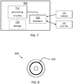
- FIG. 7 schematically illustrates, in terms of a number of functional units, the components of a sensor signal processing system 700 according to an embodiment of the discussions herein.
- Processing circuitry 710 is provided using any combination of one or more of a suitable central processing unit CPU, multiprocessor, microcontroller, digital signal processor DSP, etc., capable of executing software instructions stored in a computer program product, e.g. in the form of a storage medium 730.
- the processing circuitry 710 may further be provided as at least one application specific integrated circuit ASIC, or field programmable gate array FPGA.
- the processing circuitry thus comprises a plurality of digital logic components.
- the processing circuitry 710 is configured to cause the system 700 to perform a set of operations, or steps.
- the storage medium 730 may store the set of operations
- the processing circuitry 710 may be configured to retrieve the set of operations from the storage medium 730 to cause the system 700 to perform the set of operations.
- the set of operations may be provided as a set of executable instructions.
- the processing circuitry 710 is thereby arranged to execute methods as herein disclosed.
- the storage medium 730 may also comprise persistent storage, which, for example, can be any single one or combination of magnetic memory, optical memory, solid state memory or even remotely mounted memory.
- the sensor signal processing system 700 further comprises an interface 720 for communications with at least one external device, such as a vehicle sensor 111, and a V2X transceiver 112.
- the interface 720 may comprise one or more transmitters and receivers, comprising analogue and digital components and a suitable number of ports for wireline communication.
- the V2X transceiver 112 and the vehicle sensor 111 may be integrated into a single unit, possibly also comprising the interface 720.
- the processing circuitry 710 controls the general operation of the system 700, e.g. by sending data and control signals to the interface 720 and the storage medium 730, by receiving data and reports from the interface 720, and by retrieving data and instructions from the storage medium 730.
- Other components, as well as the related functionality, of the control node are omitted in order not to obscure the concepts presented herein.
- the sensor signal processing system 700 is, as discussed above, arranged to trigger transmission of an information signal 115 to a target vehicle 120.
- the processing circuitry is arranged to; obtain target vehicle data comprising a location of the target vehicle 120; obtain occluding object data comprising a location of an occluding object 130; determine an occluded area 140 based on the target vehicle data and on the occluded object data, wherein the occluded area 140 represents an area that is hidden from the target vehicle 120 due to the occluding object 130; and, if a potential hazard 150, 150' is detected in the occluded area 140, trigger transmission of the information signal 115 to the target vehicle 120, wherein the information signal comprises information related to the potential hazard 150.
- Figure 8 shows a computer program product 800 comprising computer executable instructions 810 to execute any of the methods disclosed herein.
Landscapes
- Physics & Mathematics (AREA)
- General Physics & Mathematics (AREA)
- Traffic Control Systems (AREA)
Abstract
obtaining target vehicle data comprising a location of the target vehicle;
obtaining occluding object data comprising a location of an occluding object;
determining an occluded area based on the target vehicle data and on the occluded object data, wherein the occluded area represents an area that is hidden from the target vehicle due to the occluding object;
and, if a potential hazard is detected in the occluded area,
triggering transmission of the information signal to the target vehicle, wherein the information signal comprises information related to the potential hazard.
Description
- The present disclosure relates to a combination of sensor systems and communication systems for use in a vehicle or traffic infrastructure. There are disclosed methods and devices for alleviating problems related to potentially hazardous occluded objects in a traffic environment.
- A number of accidents occur throughout the vehicle infrastructure each year due to occlusion of potentially hazardous objects, i.e., potential hazards which cannot be detected or seen due to that the hazard is occluded or hidden from view by some static of moving object. When the hazard is finally detected, it may be too late to react or trigger emergency systems to avoid an accident.
- Vehicle to vehicle (V2V) and vehicle to infrastructure (V2I) systems, commonly referred to as V2X systems, have been proposed as a means to alleviate the problems with occluded objects. Current solutions involve objects broadcasting their positions and motion vectors using active communication devices. Other solutions involve monitoring devices installed throughout the traffic infrastructure that identify and broadcast details about potentially hazardous objects to some road users.
-
US20180319280 describes an object-detection system which uses both sensors and V2X communication to detect both visible and hidden objects. -
DE102016214316 discusses determining one or more driver vision occlusion areas that cannot be seen depending on a detected eye position of a driver and on information about the vehicle geometry. - Even if manufacturers are now starting to equip vehicles with V2X capability, market penetration will take time before these systems become truly effective. Also, some types of road users might never be connected to a V2X system, like pedestrians, cyclists and powered two-wheelers.
- There is a need for further improvements when it comes to detecting potentially hazardous occluded objects in traffic environments.
- It is an object of the present disclosure to provide improved methods for V2X communication which address problems related to occluded objects. This object is at least partly obtained by a method in a vehicle signal processing system for triggering transmission of an information signal to a target vehicle. The method comprises obtaining target vehicle data comprising a location of the target vehicle and obtaining occluding object data comprising a location of an occluding object. The method also comprises determining an occluded area based on the target vehicle data and on the occluded object data, wherein the occluded area represents an area that is hidden from the target vehicle due to the occluding object. If a potential hazard is detected in the occluded area, transmission of the information signal to the target vehicle is triggered, wherein the information signal comprises information related to the potential hazard.
- This way communications resources such as time and bandwidth are conserved since the information signal is only transmitted in case the potential hazard is occluded. Otherwise, it is assumed that the hazard is detected by the target vehicle. Consequently, the number of unnecessary warning signal transmissions is reduced.
- According to aspects, the occluding object data comprises information related to an orientation and/or spatial extension of the occluding object. This way a more refined estimate of the occluded area can be generated based on, e.g., ray-tracing techniques.
- According to aspects, the target vehicle data comprises information related to at least one field of view of the target vehicle. The field of view can be that of one or more sensors and can also comprise that of a driver gaze.
- According to aspects, an ego vehicle comprising the vehicle signal processing system constitutes the occluding object. Thus, the ego vehicle may warn other road users about potential hazardous situations due to occlusion.
- According to aspects, the information signal is arranged to trigger a warning system and/or a control maneuver in the target vehicle. This way efficient and automatic accident prevention can be realized.
- According to aspects, the method comprises determining a threat level associated with the potential hazard with respect to the target vehicle and triggering transmission in case the threat level meets a severity criterion. This way communications resources are further conserved in that only severe enough hazards are triggering transmission of the information signal.
- There are also disclosed herein signal processing devices, systems, vehicles, and computer program products associated with the above-mentioned advantages.
- The present disclosure will now be described in detail with reference to the appended drawings, where:
-
Figure 1 schematically illustrates a vehicle with a V2X transceiver and one or more on-board sensors; -
Figures 2-3 shows example scenarios comprising occluded objects; -
Figure 4-5 schematically illustrate occluded areas; -
Figure 6 is a flow chart illustrating methods; -
Figure 7 shows an example sensor signal processing system; and -
Figure 8 illustrates an example computer program product. - Aspects of the present disclosure will now be described more fully hereinafter with reference to the accompanying drawings. The different arrangements, devices, systems, computer programs and methods disclosed herein can, however, be realized in many different forms and should not be construed as being limited to the aspects set forth herein. Like numbers in the drawings refer to like elements throughout.
- The terminology used herein is for describing aspects of the disclosure only and is not intended to limit the invention. As used herein, the singular forms "a", "an" and "the" are intended to include the plural forms as well, unless the context clearly indicates otherwise.
-
Figure 1 shows avehicle 110 comprising at least onesensor 111. Thesensor 111 is associated with a field of view (FoV) 125. The sensor may, e.g., be a radar or lidar sensor which detects objects in the sensor field of view. A vehicle may comprise a plurality of on-board sensors of different types and having different fields of view. These sensors provide information about a surrounding environment of the ego vehicle. - The techniques and methods disclosed herein are applicable to a wide variety of on-board sensor data types, including radar sensor data and lidar sensor data, but also, e.g., vision-related sensors such as camera and IR sensors, as well as ultrasound sensors.
- In addition to sensors FoV, the driver and possibly also passengers in the
vehicle 110 have fields of view. Gaze tracking systems can be used to monitor where the driver is looking, and which areas that are hidden from the driver field of view. Herein, a field of view is to be interpreted as that of one or more sensors, and/or that of a driver or passenger. - Herein, velocities, locations and areas may be determined with reference to global coordinate system, like WGS-84, or they may be relative quantities determined with respect to some local coordinate system, such as a local coordinate system defined based on an ego vehicle location and heading.
- An object detected by a sensor is herein denoted a
sensor detection 160. A sensor detection may comprise different types of information depending on the type of sensor that is used. For instance, a radar sensor provides sensor data comprising distances to detected objects, and often also a relative velocity of the object with respect to the radar transceiver. Radar sensors providing Doppler information are particularly suitable for obtaining joint range and relative velocity sensor data. Some radar sensors also provide angle information, e.g., relative to a bore-sight direction of the sensor transceiver. - Commonly, the raw sensor data is generated at a high rate and often also at a high resolution, implying that large quantities of data are generated. This means that raw sensor data consumes considerable communications resources, such as time and/or bandwidth, if it is to be communicated over the air as-is. It is preferred to limit the amount of communicated data, and thus also the occupied communications resources.
- The
vehicle 110 also comprises asignal processing unit 700. This unit will be discussed in more detail below in connection toFigure 7 . - The
vehicle 110 is equipped forV2X communications 115. This means that the vehicle comprises atransceiver 112 arranged for communicating with other transceivers in the traffic environment via V2X. These other transceivers may be comprised in other vehicles, or attached to devices in the traffic infrastructure, and also radio base stations deployed throughout the environment. - The methods disclosed herein limit the amount of information communicated via V2X by first determining occluded areas which are hidden from the viewpoint of some target vehicle. If a potential hazard is detected in the occluded area, an information transmission is triggered. This way only a limited amount of information is transmitted via V2X, since hazards outside of the occluded area does not trigger transmissions. The transmissions that are actually triggered are more likely to comprise relevant information not already detectable by, e.g., on-board sensors at the target vehicle or by eyesight from the target vehicle driver.
- For example, if on-board calculations show that there is no direct line of sight, either occluded by dynamic or static objects, between a road user and an object, and that there is some threat level or hazard associated with the road user and the object, an information or warning transmission may be warranted. If on-board calculations instead show that a clear line of sight exists between the road user and the object, then a warning transmission may be redundant.
- The proposed methods will now be illustrated through some example non-limiting scenarios.
-
Figure 2 illustrates ascenario 200 where avehicle 120 is about to turn left at, e.g., an intersection. There is anothervehicle 110 waiting to turn left which is obstructing the view of thevehicle 120. Drivers look for a clear path in one direction at a time and in many cases misses theoccluded vehicle 150 which therefore constitutes a potential hazard. The hazard in this case is the potential collision which will occur if both vehicles continue in the same headings and with thesame velocities vehicles - The proposed method here first determines an
occluded area 140 based on data obtained from the oncomingvehicle 120 and the location of the occludingobject 130. The method detects the potential hazard, i.e., theother vehicle 150, in the occluded area, and therefore triggers transmission of a warning signal informing thevehicle 120 about the oncomingother vehicle 150. This way one or bothvehicles -
Figure 3 illustrates ascenario 300 where a pedestrian 150' is crossing astreet 310. The pedestrian is hidden from avehicle 120 approaching the crossing but is detected by anothervehicle 110 which at the same time is an occludingobject 130 occluding the view from thevehicle 120. The position and movement of the pedestrian 150' can in this case be communicated to theincoming vehicle 120 to avoid collision. This could, e.g., be done by warning the driver, signaling to the pedestrian (by both vehicles) or triggering an AEB system at thevehicle 120. Consequently, in thisscenario 300 the method again determines an extent of anoccluded area 140, detects the potential hazard (the pedestrian) in theoccluded area 140, and therefore triggers transmission of an information signal or a warning signal via V2X. -
Figure 4 illustrates an example of how anoccluded area 140 can be determined based on trigonometry. Here, theoccluded area 140 is determined as asector 400 having acenter 410 at thetarget vehicle 120. Anarc 420 and an orientation 430 of thesector 400 is determined based on the location of the occludingobject 130 in relation to thetarget vehicle 120. The part of thesector 400 behind the occluding object constitutes the occluded area. - If the spatial configuration of the occluding object is known, then the occluded area can be refined. For instance, all lines of sight comprised in a field of view (either eyesight or other sensor) defines a visible area. The
occluded area 140 is then the part of the environment not comprised in the visible area. - According to other aspects, a total field of view is first determined. The
occluded area 140 is then determined as the part of the environment not comprised in the field of view. -
Figure 5 shows an example where several objects occlude a sensor field of view. Theoccluded area target vehicle 120. - In general, the
occluded area 140 can be determined in a number of different ways with varying complexity. The occluded area can be roughly estimated or be determined in a more refined manner. - As mentioned above, the proposed methods may be advantageously combined with eye tracking or gaze tracking functions. Such functions may monitor where, e.g., a driver has directed his or her gaze during a current time window. A field of view can then be defined as an area covered by a drivers' gaze in a recent time period.
-
Figure 6 is a flow chart illustrating methods. In particular, there is illustrated a method in a vehiclesignal processing system 700, for triggering transmission of aninformation signal 115 to atarget vehicle 120. The method comprises obtaining S1 target vehicle data comprising a location of thetarget vehicle 120. The target vehicle data may, according to aspects, also comprise additional data such as heading, velocity, and the like. The vehicle data may furthermore comprise information related to a field of view of the target vehicle. The target vehicle data may be obtained from on-board sensors, or via V2X transmission, or from a combination of different sources including fromstorage 730. - The method also comprises obtaining S2 occluding object data comprising a location of an occluding
object 130. The occluding object data may also be obtained from on-board sensors or via V2X transmission, or from a combination of V2X transmission and on-board sensors, including fromstorage 730. The occluding object may be anego vehicle 110, or it may be some other object, like a building. - The proposed method then determines S3 an
occluded area 140 based on the target vehicle data and on the occluded object data. Theoccluded area 140 here represents an area that is hidden from thetarget vehicle 120 due to the occludingobject 130. Some examples of the determining of the occluded area were given in connection toFigures 4 and 5 . - If a
potential hazard 150, 150' is detected S4 in theoccluded area 140, then transmission of aninformation signal 115 comprising information related to the potential hazard to thetarget vehicle 120 is triggered S5. - According to aspects, the
potential hazard 150 is detected S41 by one or more on-board sensors comprised in theego vehicle 110. Potential hazards may of course also be detected by external sensors, by eye sight, or by other vehicles, which data is then communicated to the signal processing system 600. - Examples of potential hazards may comprise any of;
A potential collision with an oncoming vehicle determined based on extrapolations 121,151 of motion tracks of the oncoming vehicle and thetarget vehicle 120. - A potential collision with a pedestrian or animal based on an
extrapolation 121 of a motion track of thetarget vehicle 120. - A potential collision with a fixed object based on an
extrapolation 121 of a motion track of thetarget vehicle 120. - According to some aspects, the occluding object data comprises information related to an orientation and/or spatial extension of the occluding object. This allows for a more accurate determination of the extent of the occluded area. In general, the determination of the occluded area can be based on geometrical relationships, such as straight lines, angles, and the like. For instance, the occluded area can be determined as all lines of view which cross the occluding object at some point, for instance as illustrated in
Figures 2 and inFigure 3 . - As mentioned above, according to aspects, the target vehicle data comprises information related to at least one field of
view 125 of thetarget vehicle 120. This again allows for a more accurate determination of the extent of theoccluded area 140. For instance, theoccluded area 140 can now be determined as comprising any line of view not comprised in the field of view. According to some aspects, gaze tracking functions are combined with the proposed methods to determine fields of view and occluded areas. A V2X transceiver vehicle may then enquire some other target vehicle to check if a potential hazard has been detected by the driver, or if a warning signal should be issued. The method may also comprise enquiring via V2X to check if a potential hazard has been detected by the target vehicle or not. In case the hazard has been detected already, then the information signal need not be triggered. This way redundant information signal transmissions can be avoided, which is an advantage. - According to some aspects, the
occluded area 140 is determined as asector 400 having acenter 410 at thetarget vehicle 120, wherein anarc 420 and an orientation 430 of thesector 400 is determined based on the location of the occludingobject 130 in relation to thetarget vehicle 120. Asector 400 like this was discussed above in connection toFigure 4 . Lines are drawn out from, e.g., a sensor location which pass corners of the occludingobject 130. The area between the two lines behind the occluding object is then considered hidden from view. The spatial extension and orientation of the occluding object can, if not known, be assumed equal to some pre-configured values. A safety margin can be applied, i.e., the occluded area may be enlarged somewhat in order to account for any measurement errors and other uncertainties. - According to some other aspects, the
occluded area 140 is determined as apolygon 400 based on the location of the occludingobject 130, or based on a plurality of occluding objects, in relation to thetarget vehicle 120. One such example was discussed above in connection toFigure 5 . The determination of the occluded area is of course improved if additional information becomes available, such as the field of view of the target vehicle, and/or the spatial configuration of the occluding object. - It is furthermore appreciated that the
occluded area 140 can be determined as the part of the traffic environment not comprised in the field of view of thetarget vehicle 120. Thus, the field ofview 125 is first determined, from which theoccluded area 140 follows. - According to some other aspects, the
occluded area 140 is a pre-determined area configured in dependence of a current scenario. In this case the occluded area can be pre-configured manually based on scenario. For instance, a given intersection may be associated with occluded areas which have been surveyed in advance. The determining then comprises detecting a set of prerequisites, i.e., oncoming vehicle locations, and then mapping the prerequisites to the pre-configured areas. For example, in case a vehicle enters this pre-defined region at the same time as another vehicle enters another pre-defined region, then the two vehicles are assumed hidden from each other's view. - According to some aspects, the method also comprises generating and transmitting S6 the
information signal 115. The transmission may be over, e.g., 802.11p, DSRC, cellular communications, or the like. - According to aspects, the information signal 115 is arranged to trigger a warning system and/or a control maneuver in the
target vehicle 120, such as an AEB system or the like. - According to aspects, the method also comprises determining S42 a threat level associated with the
potential hazard 150 with respect to thetarget vehicle 120 and triggering transmission S51 in case the threat level meets a severity criterion. This way communicated information is further limited to only comprise information relevant to more severe scenarios. -
Figure 7 schematically illustrates, in terms of a number of functional units, the components of a sensorsignal processing system 700 according to an embodiment of the discussions herein.Processing circuitry 710 is provided using any combination of one or more of a suitable central processing unit CPU, multiprocessor, microcontroller, digital signal processor DSP, etc., capable of executing software instructions stored in a computer program product, e.g. in the form of astorage medium 730. Theprocessing circuitry 710 may further be provided as at least one application specific integrated circuit ASIC, or field programmable gate array FPGA. The processing circuitry thus comprises a plurality of digital logic components. - Particularly, the
processing circuitry 710 is configured to cause thesystem 700 to perform a set of operations, or steps. For example, thestorage medium 730 may store the set of operations, and theprocessing circuitry 710 may be configured to retrieve the set of operations from thestorage medium 730 to cause thesystem 700 to perform the set of operations. The set of operations may be provided as a set of executable instructions. Thus, theprocessing circuitry 710 is thereby arranged to execute methods as herein disclosed. - The
storage medium 730 may also comprise persistent storage, which, for example, can be any single one or combination of magnetic memory, optical memory, solid state memory or even remotely mounted memory. - The sensor
signal processing system 700 further comprises aninterface 720 for communications with at least one external device, such as avehicle sensor 111, and aV2X transceiver 112. As such theinterface 720 may comprise one or more transmitters and receivers, comprising analogue and digital components and a suitable number of ports for wireline communication. TheV2X transceiver 112 and thevehicle sensor 111 may be integrated into a single unit, possibly also comprising theinterface 720. - The
processing circuitry 710 controls the general operation of thesystem 700, e.g. by sending data and control signals to theinterface 720 and thestorage medium 730, by receiving data and reports from theinterface 720, and by retrieving data and instructions from thestorage medium 730. Other components, as well as the related functionality, of the control node are omitted in order not to obscure the concepts presented herein. - The sensor
signal processing system 700 is, as discussed above, arranged to trigger transmission of aninformation signal 115 to atarget vehicle 120. Towards this end, the processing circuitry is arranged to;
obtain target vehicle data comprising a location of thetarget vehicle 120;
obtain occluding object data comprising a location of an occludingobject 130;
determine anoccluded area 140 based on the target vehicle data and on the occluded object data, wherein theoccluded area 140 represents an area that is hidden from thetarget vehicle 120 due to the occludingobject 130;
and, if apotential hazard 150, 150' is detected in theoccluded area 140,
trigger transmission of the information signal 115 to thetarget vehicle 120, wherein the information signal comprises information related to thepotential hazard 150. -
Figure 8 shows acomputer program product 800 comprising computerexecutable instructions 810 to execute any of the methods disclosed herein.
Claims (15)
- A method in a vehicle signal processing system (600), for triggering transmission of an information signal (115) to a target vehicle (120), the method comprising;
obtaining (S1) target vehicle data comprising a location of the target vehicle (120);
obtaining (S2) occluding object data comprising a location of an occluding object (130);
determining (S3) an occluded area (140) based on the target vehicle data and on the occluded object data, wherein the occluded area (140) represents an area that is hidden from the target vehicle (120) due to the occluding object (130);
and, if a potential hazard (150, 150') is detected (S4) in the occluded area (140),
triggering (S5) transmission of the information signal (115) to the target vehicle (120), wherein the information signal comprises information related to the potential hazard (150). - The method according to claim 1, wherein the occluding object data comprises information related to an orientation and/or spatial extension of the occluding object.
- The method according to any previous claim, wherein the target vehicle data comprises information related to at least one field of view (125) of the target vehicle (120).
- The method according to any previous claim, wherein the occluded area (140) is determined as a sector (400) having a center (410) at the target vehicle (120), wherein an arc (420) and an orientation (430) of the sector (400) is determined based on the location of the occluding object (130) in relation to the target vehicle (120).
- The method according to any of claims 1-3, wherein the occluded area (140) is determined as a polygon (400) based on the location of the occluding object (130), or based on a plurality of occluding objects, in relation to the target vehicle (120) .
- The method according to any of claims 1-3, wherein the occluded area (140) is a pre-determined area configured in dependence of a current scenario.
- The method according to any previous claim, wherein an ego vehicle (110) comprising the vehicle signal processing system (600) constitutes the occluding object (130).
- The method according to any previous claim, wherein the potential hazard (150) is detected (S41) by one or more on-board sensors comprised in the ego vehicle (110).
- The method according to any previous claim, comprising generating and transmitting (S6) the information signal (115).
- The method according to any previous claim, wherein the information signal (115) is arranged to trigger a warning system and/or a control maneuver in the target vehicle (120).
- The method according to any previous claim, comprising determining (S42) a threat level associated with the potential hazard (150) with respect to the target vehicle (120), and triggering transmission (S51) in case the threat level meets a severity criterion.
- The method according to any previous claim, wherein the potential hazard (150) comprises a potential collision with an oncoming vehicle determined based on extrapolations (121,151) of motion tracks of the oncoming vehicle and the target vehicle (120) .
- The method according to any of claims 1-10, wherein the potential hazard (150) comprises a potential collision with a pedestrian or animal based on an extrapolation (121) of a motion track of the target vehicle (120).
- The method according to any of claims 1-10, wherein the potential hazard (150) comprises a potential collision with a fixed object based on an extrapolation (121) of a motion track of the target vehicle (120).
- A sensor signal processing system (700) arranged to trigger transmission of an information signal (115) to a target vehicle (120), the sensor signal processing system comprising processing circuitry arranged to;
obtain target vehicle data comprising a location of the target vehicle (120);
obtain occluding object data comprising a location of an occluding object (130);
determine an occluded area (140) based on the target vehicle data and on the occluded object data, wherein the occluded area (140) represents an area that is hidden from the target vehicle (120) due to the occluding object (130);
and, if a potential hazard (150, 150') is detected in the occluded area (140),
trigger transmission of the information signal (115) to the target vehicle (120), wherein the information signal comprises information related to the potential hazard (150).
Priority Applications (1)
| Application Number | Priority Date | Filing Date | Title |
|---|---|---|---|
| EP19159377.1A EP3703032B1 (en) | 2019-02-26 | 2019-02-26 | Collaborative safety for occluded objects |
Applications Claiming Priority (1)
| Application Number | Priority Date | Filing Date | Title |
|---|---|---|---|
| EP19159377.1A EP3703032B1 (en) | 2019-02-26 | 2019-02-26 | Collaborative safety for occluded objects |
Publications (3)
| Publication Number | Publication Date |
|---|---|
| EP3703032A1 true EP3703032A1 (en) | 2020-09-02 |
| EP3703032C0 EP3703032C0 (en) | 2025-08-06 |
| EP3703032B1 EP3703032B1 (en) | 2025-08-06 |
Family
ID=65598512
Family Applications (1)
| Application Number | Title | Priority Date | Filing Date |
|---|---|---|---|
| EP19159377.1A Active EP3703032B1 (en) | 2019-02-26 | 2019-02-26 | Collaborative safety for occluded objects |
Country Status (1)
| Country | Link |
|---|---|
| EP (1) | EP3703032B1 (en) |
Cited By (3)
| Publication number | Priority date | Publication date | Assignee | Title |
|---|---|---|---|---|
| CN114274979A (en) * | 2022-01-07 | 2022-04-05 | 中国第一汽车股份有限公司 | Target attention degree grade distinguishing method and device for automatic driving and storage medium |
| CN115027490A (en) * | 2022-05-31 | 2022-09-09 | 中国第一汽车股份有限公司 | Hidden target early warning method and device, vehicle and storage medium |
| WO2025172121A1 (en) * | 2024-02-15 | 2025-08-21 | Mercedes-Benz Group AG | Use of vehicle sensor systems of parked vehicles for detecting concealed road users |
Citations (4)
| Publication number | Priority date | Publication date | Assignee | Title |
|---|---|---|---|---|
| US20170327035A1 (en) * | 2016-05-10 | 2017-11-16 | Ford Global Technologies, Llc | Methods and systems for beyond-the-horizon threat indication for vehicles |
| DE102016214316A1 (en) | 2016-08-03 | 2018-02-08 | Bayerische Motoren Werke Aktiengesellschaft | Method and device for detecting an object at least partially hidden by a vehicle part in a vehicle environment of a motor vehicle |
| US9910442B2 (en) * | 2016-06-28 | 2018-03-06 | Toyota Motor Engineering & Manufacturing North America, Inc. | Occluded area detection with static obstacle maps |
| US20180319280A1 (en) | 2017-05-02 | 2018-11-08 | Delphi Technologies, Inc. | Visually obstructed object detection for automated vehicle using v2v/v2i communications |
-
2019
- 2019-02-26 EP EP19159377.1A patent/EP3703032B1/en active Active
Patent Citations (4)
| Publication number | Priority date | Publication date | Assignee | Title |
|---|---|---|---|---|
| US20170327035A1 (en) * | 2016-05-10 | 2017-11-16 | Ford Global Technologies, Llc | Methods and systems for beyond-the-horizon threat indication for vehicles |
| US9910442B2 (en) * | 2016-06-28 | 2018-03-06 | Toyota Motor Engineering & Manufacturing North America, Inc. | Occluded area detection with static obstacle maps |
| DE102016214316A1 (en) | 2016-08-03 | 2018-02-08 | Bayerische Motoren Werke Aktiengesellschaft | Method and device for detecting an object at least partially hidden by a vehicle part in a vehicle environment of a motor vehicle |
| US20180319280A1 (en) | 2017-05-02 | 2018-11-08 | Delphi Technologies, Inc. | Visually obstructed object detection for automated vehicle using v2v/v2i communications |
Cited By (3)
| Publication number | Priority date | Publication date | Assignee | Title |
|---|---|---|---|---|
| CN114274979A (en) * | 2022-01-07 | 2022-04-05 | 中国第一汽车股份有限公司 | Target attention degree grade distinguishing method and device for automatic driving and storage medium |
| CN115027490A (en) * | 2022-05-31 | 2022-09-09 | 中国第一汽车股份有限公司 | Hidden target early warning method and device, vehicle and storage medium |
| WO2025172121A1 (en) * | 2024-02-15 | 2025-08-21 | Mercedes-Benz Group AG | Use of vehicle sensor systems of parked vehicles for detecting concealed road users |
Also Published As
| Publication number | Publication date |
|---|---|
| EP3703032C0 (en) | 2025-08-06 |
| EP3703032B1 (en) | 2025-08-06 |
Similar Documents
| Publication | Publication Date | Title |
|---|---|---|
| US11772489B2 (en) | Visually obstructed object detection for automated vehicle using V2V/V2I communications | |
| US7994902B2 (en) | Cooperative sensor-sharing vehicle traffic safety system | |
| EP3208165B1 (en) | Vehicle safety assist system | |
| KR102797059B1 (en) | Vehicle and method for controlling thereof | |
| EP2302412B1 (en) | System and method for evaluation of an automotive vehicle forward collision threat | |
| US9858817B1 (en) | Method and system to allow drivers or driverless vehicles to see what is on the other side of an obstruction that they are driving near, using direct vehicle-to-vehicle sharing of environment data | |
| EP1269445B1 (en) | System and method for avoiding accidents in intersections | |
| US9260059B2 (en) | False warning reduction using location data | |
| EP3044772B1 (en) | Detection of an object by use of a 3d camera and a radar | |
| US9020728B2 (en) | Vehicle turn monitoring system and method | |
| US20120101711A1 (en) | Collision Warning Apparatus | |
| US20100198513A1 (en) | Combined Vehicle-to-Vehicle Communication and Object Detection Sensing | |
| US20040051659A1 (en) | Vehicular situational awareness system | |
| CN112771592A (en) | Method and control device for warning a driver of a motor vehicle, and motor vehicle having such a control device | |
| KR20190101909A (en) | Viechle radar system for sensing danger | |
| CN110505631A (en) | The detection of malice wireless security messaging is carried out using angle of arrival | |
| KR20180111252A (en) | Drive Control Method and Device Based on Sensing Information | |
| CN108340866A (en) | anti-collision system and method | |
| EP3703032B1 (en) | Collaborative safety for occluded objects | |
| US11724692B2 (en) | Detection, warning and preparative action for vehicle contact mitigation | |
| US12487355B2 (en) | Vehicular driving assist system using radar and communication with other vehicles | |
| US20220009499A1 (en) | Vehicle control system | |
| WO2016126318A1 (en) | Method of automatically controlling an autonomous vehicle based on cellular telephone location information | |
| US12397781B2 (en) | System and method for controlling vehicle | |
| CN210617998U (en) | Blind area detection equipment for freight transport and passenger transport vehicles |
Legal Events
| Date | Code | Title | Description |
|---|---|---|---|
| PUAI | Public reference made under article 153(3) epc to a published international application that has entered the european phase |
Free format text: ORIGINAL CODE: 0009012 |
|
| STAA | Information on the status of an ep patent application or granted ep patent |
Free format text: STATUS: THE APPLICATION HAS BEEN PUBLISHED |
|
| AK | Designated contracting states |
Kind code of ref document: A1 Designated state(s): AL AT BE BG CH CY CZ DE DK EE ES FI FR GB GR HR HU IE IS IT LI LT LU LV MC MK MT NL NO PL PT RO RS SE SI SK SM TR |
|
| AX | Request for extension of the european patent |
Extension state: BA ME |
|
| STAA | Information on the status of an ep patent application or granted ep patent |
Free format text: STATUS: REQUEST FOR EXAMINATION WAS MADE |
|
| 17P | Request for examination filed |
Effective date: 20210226 |
|
| RBV | Designated contracting states (corrected) |
Designated state(s): AL AT BE BG CH CY CZ DE DK EE ES FI FR GB GR HR HU IE IS IT LI LT LU LV MC MK MT NL NO PL PT RO RS SE SI SK SM TR |
|
| RAP1 | Party data changed (applicant data changed or rights of an application transferred) |
Owner name: ARRIVER SOFTWARE AB |
|
| STAA | Information on the status of an ep patent application or granted ep patent |
Free format text: STATUS: EXAMINATION IS IN PROGRESS |
|
| 17Q | First examination report despatched |
Effective date: 20240813 |
|
| RAP1 | Party data changed (applicant data changed or rights of an application transferred) |
Owner name: QUALCOMM AUTO LTD. |
|
| GRAP | Despatch of communication of intention to grant a patent |
Free format text: ORIGINAL CODE: EPIDOSNIGR1 |
|
| STAA | Information on the status of an ep patent application or granted ep patent |
Free format text: STATUS: GRANT OF PATENT IS INTENDED |
|
| INTG | Intention to grant announced |
Effective date: 20250228 |
|
| GRAS | Grant fee paid |
Free format text: ORIGINAL CODE: EPIDOSNIGR3 |
|
| GRAA | (expected) grant |
Free format text: ORIGINAL CODE: 0009210 |
|
| STAA | Information on the status of an ep patent application or granted ep patent |
Free format text: STATUS: THE PATENT HAS BEEN GRANTED |
|
| AK | Designated contracting states |
Kind code of ref document: B1 Designated state(s): AL AT BE BG CH CY CZ DE DK EE ES FI FR GB GR HR HU IE IS IT LI LT LU LV MC MK MT NL NO PL PT RO RS SE SI SK SM TR |
|
| REG | Reference to a national code |
Ref country code: GB Ref legal event code: FG4D |
|
| REG | Reference to a national code |
Ref country code: CH Ref legal event code: EP |
|
| REG | Reference to a national code |
Ref country code: IE Ref legal event code: FG4D |
|
| REG | Reference to a national code |
Ref country code: DE Ref legal event code: R096 Ref document number: 602019073565 Country of ref document: DE |
|
| U01 | Request for unitary effect filed |
Effective date: 20250821 |
|
| U07 | Unitary effect registered |
Designated state(s): AT BE BG DE DK EE FI FR IT LT LU LV MT NL PT RO SE SI Effective date: 20250827 |
|
| PG25 | Lapsed in a contracting state [announced via postgrant information from national office to epo] |
Ref country code: IS Free format text: LAPSE BECAUSE OF FAILURE TO SUBMIT A TRANSLATION OF THE DESCRIPTION OR TO PAY THE FEE WITHIN THE PRESCRIBED TIME-LIMIT Effective date: 20251206 |
|
| PG25 | Lapsed in a contracting state [announced via postgrant information from national office to epo] |
Ref country code: NO Free format text: LAPSE BECAUSE OF FAILURE TO SUBMIT A TRANSLATION OF THE DESCRIPTION OR TO PAY THE FEE WITHIN THE PRESCRIBED TIME-LIMIT Effective date: 20251106 |
|
| PG25 | Lapsed in a contracting state [announced via postgrant information from national office to epo] |
Ref country code: HR Free format text: LAPSE BECAUSE OF FAILURE TO SUBMIT A TRANSLATION OF THE DESCRIPTION OR TO PAY THE FEE WITHIN THE PRESCRIBED TIME-LIMIT Effective date: 20250806 |
|
| PG25 | Lapsed in a contracting state [announced via postgrant information from national office to epo] |
Ref country code: GR Free format text: LAPSE BECAUSE OF FAILURE TO SUBMIT A TRANSLATION OF THE DESCRIPTION OR TO PAY THE FEE WITHIN THE PRESCRIBED TIME-LIMIT Effective date: 20251107 |
|
| PG25 | Lapsed in a contracting state [announced via postgrant information from national office to epo] |
Ref country code: PL Free format text: LAPSE BECAUSE OF FAILURE TO SUBMIT A TRANSLATION OF THE DESCRIPTION OR TO PAY THE FEE WITHIN THE PRESCRIBED TIME-LIMIT Effective date: 20250806 |
|
| PG25 | Lapsed in a contracting state [announced via postgrant information from national office to epo] |
Ref country code: RS Free format text: LAPSE BECAUSE OF FAILURE TO SUBMIT A TRANSLATION OF THE DESCRIPTION OR TO PAY THE FEE WITHIN THE PRESCRIBED TIME-LIMIT Effective date: 20251106 |
|
| PG25 | Lapsed in a contracting state [announced via postgrant information from national office to epo] |
Ref country code: ES Free format text: LAPSE BECAUSE OF FAILURE TO SUBMIT A TRANSLATION OF THE DESCRIPTION OR TO PAY THE FEE WITHIN THE PRESCRIBED TIME-LIMIT Effective date: 20250806 |
|
| U20 | Renewal fee for the european patent with unitary effect paid |
Year of fee payment: 8 Effective date: 20260112 |
|
| PG25 | Lapsed in a contracting state [announced via postgrant information from national office to epo] |
Ref country code: SM Free format text: LAPSE BECAUSE OF FAILURE TO SUBMIT A TRANSLATION OF THE DESCRIPTION OR TO PAY THE FEE WITHIN THE PRESCRIBED TIME-LIMIT Effective date: 20250806 |
|
| PGFP | Annual fee paid to national office [announced via postgrant information from national office to epo] |
Ref country code: GB Payment date: 20260113 Year of fee payment: 8 |
|
| PGFP | Annual fee paid to national office [announced via postgrant information from national office to epo] |
Ref country code: IE Payment date: 20260109 Year of fee payment: 8 |
|
| PG25 | Lapsed in a contracting state [announced via postgrant information from national office to epo] |
Ref country code: CZ Free format text: LAPSE BECAUSE OF FAILURE TO SUBMIT A TRANSLATION OF THE DESCRIPTION OR TO PAY THE FEE WITHIN THE PRESCRIBED TIME-LIMIT Effective date: 20250806 |
|
| PG25 | Lapsed in a contracting state [announced via postgrant information from national office to epo] |
Ref country code: SK Free format text: LAPSE BECAUSE OF FAILURE TO SUBMIT A TRANSLATION OF THE DESCRIPTION OR TO PAY THE FEE WITHIN THE PRESCRIBED TIME-LIMIT Effective date: 20250806 |
|
| PLBE | No opposition filed within time limit |
Free format text: ORIGINAL CODE: 0009261 |
|
| STAA | Information on the status of an ep patent application or granted ep patent |
Free format text: STATUS: NO OPPOSITION FILED WITHIN TIME LIMIT |
|
| REG | Reference to a national code |
Ref country code: CH Ref legal event code: L10 Free format text: ST27 STATUS EVENT CODE: U-0-0-L10-L00 (AS PROVIDED BY THE NATIONAL OFFICE) Effective date: 20260617 |
|
| 26N | No opposition filed |
Effective date: 20260507 |