EP3702970A1 - Encoded cells and cell arrays - Google Patents
Encoded cells and cell arrays Download PDFInfo
- Publication number
- EP3702970A1 EP3702970A1 EP20170695.9A EP20170695A EP3702970A1 EP 3702970 A1 EP3702970 A1 EP 3702970A1 EP 20170695 A EP20170695 A EP 20170695A EP 3702970 A1 EP3702970 A1 EP 3702970A1
- Authority
- EP
- European Patent Office
- Prior art keywords
- cell
- alignment
- cells
- encoded
- cell array
- Prior art date
- Legal status (The legal status is an assumption and is not a legal conclusion. Google has not performed a legal analysis and makes no representation as to the accuracy of the status listed.)
- Granted
Links
- 238000003491 array Methods 0.000 title description 13
- 238000000034 method Methods 0.000 claims abstract description 241
- 239000003086 colorant Substances 0.000 claims abstract description 127
- 239000013598 vector Substances 0.000 claims abstract description 58
- 230000006870 function Effects 0.000 claims description 147
- 238000004519 manufacturing process Methods 0.000 claims description 100
- 239000002243 precursor Substances 0.000 claims description 53
- 230000001413 cellular effect Effects 0.000 claims description 8
- 210000004027 cell Anatomy 0.000 description 1997
- 238000004891 communication Methods 0.000 description 56
- 210000004287 null lymphocyte Anatomy 0.000 description 25
- 210000005056 cell body Anatomy 0.000 description 9
- 238000010586 diagram Methods 0.000 description 5
- 239000002184 metal Substances 0.000 description 5
- 239000004033 plastic Substances 0.000 description 5
- MJUVRTYWUMPBTR-MRXNPFEDSA-N 1-(2,2-difluoro-1,3-benzodioxol-5-yl)-n-[1-[(2r)-2,3-dihydroxypropyl]-6-fluoro-2-(1-hydroxy-2-methylpropan-2-yl)indol-5-yl]cyclopropane-1-carboxamide Chemical compound FC=1C=C2N(C[C@@H](O)CO)C(C(C)(CO)C)=CC2=CC=1NC(=O)C1(C=2C=C3OC(F)(F)OC3=CC=2)CC1 MJUVRTYWUMPBTR-MRXNPFEDSA-N 0.000 description 4
- 239000011521 glass Substances 0.000 description 4
- 239000011159 matrix material Substances 0.000 description 4
- YFCIFWOJYYFDQP-PTWZRHHISA-N 4-[3-amino-6-[(1S,3S,4S)-3-fluoro-4-hydroxycyclohexyl]pyrazin-2-yl]-N-[(1S)-1-(3-bromo-5-fluorophenyl)-2-(methylamino)ethyl]-2-fluorobenzamide Chemical compound CNC[C@@H](NC(=O)c1ccc(cc1F)-c1nc(cnc1N)[C@H]1CC[C@H](O)[C@@H](F)C1)c1cc(F)cc(Br)c1 YFCIFWOJYYFDQP-PTWZRHHISA-N 0.000 description 3
- KVCQTKNUUQOELD-UHFFFAOYSA-N 4-amino-n-[1-(3-chloro-2-fluoroanilino)-6-methylisoquinolin-5-yl]thieno[3,2-d]pyrimidine-7-carboxamide Chemical compound N=1C=CC2=C(NC(=O)C=3C4=NC=NC(N)=C4SC=3)C(C)=CC=C2C=1NC1=CC=CC(Cl)=C1F KVCQTKNUUQOELD-UHFFFAOYSA-N 0.000 description 3
- CYJRNFFLTBEQSQ-UHFFFAOYSA-N 8-(3-methyl-1-benzothiophen-5-yl)-N-(4-methylsulfonylpyridin-3-yl)quinoxalin-6-amine Chemical compound CS(=O)(=O)C1=C(C=NC=C1)NC=1C=C2N=CC=NC2=C(C=1)C=1C=CC2=C(C(=CS2)C)C=1 CYJRNFFLTBEQSQ-UHFFFAOYSA-N 0.000 description 3
- 239000000853 adhesive Substances 0.000 description 3
- 230000001070 adhesive effect Effects 0.000 description 3
- 230000003287 optical effect Effects 0.000 description 3
- UKGJZDSUJSPAJL-YPUOHESYSA-N (e)-n-[(1r)-1-[3,5-difluoro-4-(methanesulfonamido)phenyl]ethyl]-3-[2-propyl-6-(trifluoromethyl)pyridin-3-yl]prop-2-enamide Chemical compound CCCC1=NC(C(F)(F)F)=CC=C1\C=C\C(=O)N[C@H](C)C1=CC(F)=C(NS(C)(=O)=O)C(F)=C1 UKGJZDSUJSPAJL-YPUOHESYSA-N 0.000 description 2
- MOWXJLUYGFNTAL-DEOSSOPVSA-N (s)-[2-chloro-4-fluoro-5-(7-morpholin-4-ylquinazolin-4-yl)phenyl]-(6-methoxypyridazin-3-yl)methanol Chemical compound N1=NC(OC)=CC=C1[C@@H](O)C1=CC(C=2C3=CC=C(C=C3N=CN=2)N2CCOCC2)=C(F)C=C1Cl MOWXJLUYGFNTAL-DEOSSOPVSA-N 0.000 description 2
- ABDDQTDRAHXHOC-QMMMGPOBSA-N 1-[(7s)-5,7-dihydro-4h-thieno[2,3-c]pyran-7-yl]-n-methylmethanamine Chemical compound CNC[C@@H]1OCCC2=C1SC=C2 ABDDQTDRAHXHOC-QMMMGPOBSA-N 0.000 description 2
- 241000237519 Bivalvia Species 0.000 description 2
- AYCPARAPKDAOEN-LJQANCHMSA-N N-[(1S)-2-(dimethylamino)-1-phenylethyl]-6,6-dimethyl-3-[(2-methyl-4-thieno[3,2-d]pyrimidinyl)amino]-1,4-dihydropyrrolo[3,4-c]pyrazole-5-carboxamide Chemical compound C1([C@H](NC(=O)N2C(C=3NN=C(NC=4C=5SC=CC=5N=C(C)N=4)C=3C2)(C)C)CN(C)C)=CC=CC=C1 AYCPARAPKDAOEN-LJQANCHMSA-N 0.000 description 2
- 230000005540 biological transmission Effects 0.000 description 2
- 235000020639 clam Nutrition 0.000 description 2
- XIIOFHFUYBLOLW-UHFFFAOYSA-N selpercatinib Chemical compound OC(COC=1C=C(C=2N(C=1)N=CC=2C#N)C=1C=NC(=CC=1)N1CC2N(C(C1)C2)CC=1C=NC(=CC=1)OC)(C)C XIIOFHFUYBLOLW-UHFFFAOYSA-N 0.000 description 2
- VCGRFBXVSFAGGA-UHFFFAOYSA-N (1,1-dioxo-1,4-thiazinan-4-yl)-[6-[[3-(4-fluorophenyl)-5-methyl-1,2-oxazol-4-yl]methoxy]pyridin-3-yl]methanone Chemical compound CC=1ON=C(C=2C=CC(F)=CC=2)C=1COC(N=C1)=CC=C1C(=O)N1CCS(=O)(=O)CC1 VCGRFBXVSFAGGA-UHFFFAOYSA-N 0.000 description 1
- DOMQFIFVDIAOOT-ROUUACIJSA-N (2S,3R)-N-[4-(2,6-dimethoxyphenyl)-5-(5-methylpyridin-3-yl)-1,2,4-triazol-3-yl]-3-(5-methylpyrimidin-2-yl)butane-2-sulfonamide Chemical compound COC1=C(C(=CC=C1)OC)N1C(=NN=C1C=1C=NC=C(C=1)C)NS(=O)(=O)[C@@H](C)[C@H](C)C1=NC=C(C=N1)C DOMQFIFVDIAOOT-ROUUACIJSA-N 0.000 description 1
- FRYGPXUFBOGTFP-UHFFFAOYSA-M (2e)-3-methyl-2-[(e)-3-(3-methyl-1,3-benzothiazol-3-ium-2-yl)prop-2-enylidene]-1,3-benzothiazole;iodide Chemical compound [I-].S1C2=CC=CC=C2[N+](C)=C1/C=C/C=C1/N(C)C2=CC=CC=C2S1 FRYGPXUFBOGTFP-UHFFFAOYSA-M 0.000 description 1
- MAYZWDRUFKUGGP-VIFPVBQESA-N (3s)-1-[5-tert-butyl-3-[(1-methyltetrazol-5-yl)methyl]triazolo[4,5-d]pyrimidin-7-yl]pyrrolidin-3-ol Chemical compound CN1N=NN=C1CN1C2=NC(C(C)(C)C)=NC(N3C[C@@H](O)CC3)=C2N=N1 MAYZWDRUFKUGGP-VIFPVBQESA-N 0.000 description 1
- ZGYIXVSQHOKQRZ-COIATFDQSA-N (e)-n-[4-[3-chloro-4-(pyridin-2-ylmethoxy)anilino]-3-cyano-7-[(3s)-oxolan-3-yl]oxyquinolin-6-yl]-4-(dimethylamino)but-2-enamide Chemical compound N#CC1=CN=C2C=C(O[C@@H]3COCC3)C(NC(=O)/C=C/CN(C)C)=CC2=C1NC(C=C1Cl)=CC=C1OCC1=CC=CC=N1 ZGYIXVSQHOKQRZ-COIATFDQSA-N 0.000 description 1
- APWRZPQBPCAXFP-UHFFFAOYSA-N 1-(1-oxo-2H-isoquinolin-5-yl)-5-(trifluoromethyl)-N-[2-(trifluoromethyl)pyridin-4-yl]pyrazole-4-carboxamide Chemical compound O=C1NC=CC2=C(C=CC=C12)N1N=CC(=C1C(F)(F)F)C(=O)NC1=CC(=NC=C1)C(F)(F)F APWRZPQBPCAXFP-UHFFFAOYSA-N 0.000 description 1
- HCDMJFOHIXMBOV-UHFFFAOYSA-N 3-(2,6-difluoro-3,5-dimethoxyphenyl)-1-ethyl-8-(morpholin-4-ylmethyl)-4,7-dihydropyrrolo[4,5]pyrido[1,2-d]pyrimidin-2-one Chemical compound C=1C2=C3N(CC)C(=O)N(C=4C(=C(OC)C=C(OC)C=4F)F)CC3=CN=C2NC=1CN1CCOCC1 HCDMJFOHIXMBOV-UHFFFAOYSA-N 0.000 description 1
- BYHQTRFJOGIQAO-GOSISDBHSA-N 3-(4-bromophenyl)-8-[(2R)-2-hydroxypropyl]-1-[(3-methoxyphenyl)methyl]-1,3,8-triazaspiro[4.5]decan-2-one Chemical compound C[C@H](CN1CCC2(CC1)CN(C(=O)N2CC3=CC(=CC=C3)OC)C4=CC=C(C=C4)Br)O BYHQTRFJOGIQAO-GOSISDBHSA-N 0.000 description 1
- YGYGASJNJTYNOL-CQSZACIVSA-N 3-[(4r)-2,2-dimethyl-1,1-dioxothian-4-yl]-5-(4-fluorophenyl)-1h-indole-7-carboxamide Chemical compound C1CS(=O)(=O)C(C)(C)C[C@@H]1C1=CNC2=C(C(N)=O)C=C(C=3C=CC(F)=CC=3)C=C12 YGYGASJNJTYNOL-CQSZACIVSA-N 0.000 description 1
- ORWQBKPSGDRPPA-UHFFFAOYSA-N 3-[2-[ethyl(methyl)amino]ethyl]-1h-indol-4-ol Chemical compound C1=CC(O)=C2C(CCN(C)CC)=CNC2=C1 ORWQBKPSGDRPPA-UHFFFAOYSA-N 0.000 description 1
- WNEODWDFDXWOLU-QHCPKHFHSA-N 3-[3-(hydroxymethyl)-4-[1-methyl-5-[[5-[(2s)-2-methyl-4-(oxetan-3-yl)piperazin-1-yl]pyridin-2-yl]amino]-6-oxopyridin-3-yl]pyridin-2-yl]-7,7-dimethyl-1,2,6,8-tetrahydrocyclopenta[3,4]pyrrolo[3,5-b]pyrazin-4-one Chemical compound C([C@@H](N(CC1)C=2C=NC(NC=3C(N(C)C=C(C=3)C=3C(=C(N4C(C5=CC=6CC(C)(C)CC=6N5CC4)=O)N=CC=3)CO)=O)=CC=2)C)N1C1COC1 WNEODWDFDXWOLU-QHCPKHFHSA-N 0.000 description 1
- SRVXSISGYBMIHR-UHFFFAOYSA-N 3-[3-[3-(2-amino-2-oxoethyl)phenyl]-5-chlorophenyl]-3-(5-methyl-1,3-thiazol-2-yl)propanoic acid Chemical compound S1C(C)=CN=C1C(CC(O)=O)C1=CC(Cl)=CC(C=2C=C(CC(N)=O)C=CC=2)=C1 SRVXSISGYBMIHR-UHFFFAOYSA-N 0.000 description 1
- VJPPLCNBDLZIFG-ZDUSSCGKSA-N 4-[(3S)-3-(but-2-ynoylamino)piperidin-1-yl]-5-fluoro-2,3-dimethyl-1H-indole-7-carboxamide Chemical compound C(C#CC)(=O)N[C@@H]1CN(CCC1)C1=C2C(=C(NC2=C(C=C1F)C(=O)N)C)C VJPPLCNBDLZIFG-ZDUSSCGKSA-N 0.000 description 1
- XYWIPYBIIRTJMM-IBGZPJMESA-N 4-[[(2S)-2-[4-[5-chloro-2-[4-(trifluoromethyl)triazol-1-yl]phenyl]-5-methoxy-2-oxopyridin-1-yl]butanoyl]amino]-2-fluorobenzamide Chemical compound CC[C@H](N1C=C(OC)C(=CC1=O)C1=C(C=CC(Cl)=C1)N1C=C(N=N1)C(F)(F)F)C(=O)NC1=CC(F)=C(C=C1)C(N)=O XYWIPYBIIRTJMM-IBGZPJMESA-N 0.000 description 1
- IRPVABHDSJVBNZ-RTHVDDQRSA-N 5-[1-(cyclopropylmethyl)-5-[(1R,5S)-3-(oxetan-3-yl)-3-azabicyclo[3.1.0]hexan-6-yl]pyrazol-3-yl]-3-(trifluoromethyl)pyridin-2-amine Chemical compound C1=C(C(F)(F)F)C(N)=NC=C1C1=NN(CC2CC2)C(C2[C@@H]3CN(C[C@@H]32)C2COC2)=C1 IRPVABHDSJVBNZ-RTHVDDQRSA-N 0.000 description 1
- KCBWAFJCKVKYHO-UHFFFAOYSA-N 6-(4-cyclopropyl-6-methoxypyrimidin-5-yl)-1-[[4-[1-propan-2-yl-4-(trifluoromethyl)imidazol-2-yl]phenyl]methyl]pyrazolo[3,4-d]pyrimidine Chemical compound C1(CC1)C1=NC=NC(=C1C1=NC=C2C(=N1)N(N=C2)CC1=CC=C(C=C1)C=1N(C=C(N=1)C(F)(F)F)C(C)C)OC KCBWAFJCKVKYHO-UHFFFAOYSA-N 0.000 description 1
- UNQYAAAWKOOBFQ-UHFFFAOYSA-N 7-[(4-chlorophenyl)methyl]-8-[4-chloro-3-(trifluoromethoxy)phenoxy]-1-(3-hydroxypropyl)-3-methylpurine-2,6-dione Chemical compound C=1C=C(Cl)C=CC=1CN1C=2C(=O)N(CCCO)C(=O)N(C)C=2N=C1OC1=CC=C(Cl)C(OC(F)(F)F)=C1 UNQYAAAWKOOBFQ-UHFFFAOYSA-N 0.000 description 1
- ZRPZPNYZFSJUPA-UHFFFAOYSA-N ARS-1620 Chemical compound Oc1cccc(F)c1-c1c(Cl)cc2c(ncnc2c1F)N1CCN(CC1)C(=O)C=C ZRPZPNYZFSJUPA-UHFFFAOYSA-N 0.000 description 1
- GISRWBROCYNDME-PELMWDNLSA-N F[C@H]1[C@H]([C@H](NC1=O)COC1=NC=CC2=CC(=C(C=C12)OC)C(=O)N)C Chemical compound F[C@H]1[C@H]([C@H](NC1=O)COC1=NC=CC2=CC(=C(C=C12)OC)C(=O)N)C GISRWBROCYNDME-PELMWDNLSA-N 0.000 description 1
- FEYNFHSRETUBEM-UHFFFAOYSA-N N-[3-(1,1-difluoroethyl)phenyl]-1-(4-methoxyphenyl)-3-methyl-5-oxo-4H-pyrazole-4-carboxamide Chemical compound COc1ccc(cc1)N1N=C(C)C(C(=O)Nc2cccc(c2)C(C)(F)F)C1=O FEYNFHSRETUBEM-UHFFFAOYSA-N 0.000 description 1
- IDRGFNPZDVBSSE-UHFFFAOYSA-N OCCN1CCN(CC1)c1ccc(Nc2ncc3cccc(-c4cccc(NC(=O)C=C)c4)c3n2)c(F)c1F Chemical compound OCCN1CCN(CC1)c1ccc(Nc2ncc3cccc(-c4cccc(NC(=O)C=C)c4)c3n2)c(F)c1F IDRGFNPZDVBSSE-UHFFFAOYSA-N 0.000 description 1
- LXRZVMYMQHNYJB-UNXOBOICSA-N [(1R,2S,4R)-4-[[5-[4-[(1R)-7-chloro-1,2,3,4-tetrahydroisoquinolin-1-yl]-5-methylthiophene-2-carbonyl]pyrimidin-4-yl]amino]-2-hydroxycyclopentyl]methyl sulfamate Chemical compound CC1=C(C=C(S1)C(=O)C1=C(N[C@H]2C[C@H](O)[C@@H](COS(N)(=O)=O)C2)N=CN=C1)[C@@H]1NCCC2=C1C=C(Cl)C=C2 LXRZVMYMQHNYJB-UNXOBOICSA-N 0.000 description 1
- 238000004458 analytical method Methods 0.000 description 1
- 229910010293 ceramic material Inorganic materials 0.000 description 1
- DGLFSNZWRYADFC-UHFFFAOYSA-N chembl2334586 Chemical compound C1CCC2=CN=C(N)N=C2C2=C1NC1=CC=C(C#CC(C)(O)C)C=C12 DGLFSNZWRYADFC-UHFFFAOYSA-N 0.000 description 1
- 238000013500 data storage Methods 0.000 description 1
- 230000009977 dual effect Effects 0.000 description 1
- 238000004043 dyeing Methods 0.000 description 1
- 238000005530 etching Methods 0.000 description 1
- 239000000835 fiber Substances 0.000 description 1
- 238000002955 isolation Methods 0.000 description 1
- 238000010147 laser engraving Methods 0.000 description 1
- 239000004973 liquid crystal related substance Substances 0.000 description 1
- 239000000463 material Substances 0.000 description 1
- 230000007246 mechanism Effects 0.000 description 1
- 238000012986 modification Methods 0.000 description 1
- 230000004048 modification Effects 0.000 description 1
- FMASTMURQSHELY-UHFFFAOYSA-N n-(4-fluoro-2-methylphenyl)-3-methyl-n-[(2-methyl-1h-indol-4-yl)methyl]pyridine-4-carboxamide Chemical compound C1=CC=C2NC(C)=CC2=C1CN(C=1C(=CC(F)=CC=1)C)C(=O)C1=CC=NC=C1C FMASTMURQSHELY-UHFFFAOYSA-N 0.000 description 1
- VFBILHPIHUPBPZ-UHFFFAOYSA-N n-[[2-[4-(difluoromethoxy)-3-propan-2-yloxyphenyl]-1,3-oxazol-4-yl]methyl]-2-ethoxybenzamide Chemical compound CCOC1=CC=CC=C1C(=O)NCC1=COC(C=2C=C(OC(C)C)C(OC(F)F)=CC=2)=N1 VFBILHPIHUPBPZ-UHFFFAOYSA-N 0.000 description 1
- NNKPHNTWNILINE-UHFFFAOYSA-N n-cyclopropyl-3-fluoro-4-methyl-5-[3-[[1-[2-[2-(methylamino)ethoxy]phenyl]cyclopropyl]amino]-2-oxopyrazin-1-yl]benzamide Chemical compound CNCCOC1=CC=CC=C1C1(NC=2C(N(C=3C(=C(F)C=C(C=3)C(=O)NC3CC3)C)C=CN=2)=O)CC1 NNKPHNTWNILINE-UHFFFAOYSA-N 0.000 description 1
- 238000010422 painting Methods 0.000 description 1
- 239000000123 paper Substances 0.000 description 1
- LZMJNVRJMFMYQS-UHFFFAOYSA-N poseltinib Chemical compound C1CN(C)CCN1C(C=C1)=CC=C1NC1=NC(OC=2C=C(NC(=O)C=C)C=CC=2)=C(OC=C2)C2=N1 LZMJNVRJMFMYQS-UHFFFAOYSA-N 0.000 description 1
- 230000004044 response Effects 0.000 description 1
- XGVXKJKTISMIOW-ZDUSSCGKSA-N simurosertib Chemical compound N1N=CC(C=2SC=3C(=O)NC(=NC=3C=2)[C@H]2N3CCC(CC3)C2)=C1C XGVXKJKTISMIOW-ZDUSSCGKSA-N 0.000 description 1
- 239000007787 solid Substances 0.000 description 1
- 238000001429 visible spectrum Methods 0.000 description 1
- 239000002023 wood Substances 0.000 description 1
Images


Classifications
-
- G—PHYSICS
- G06—COMPUTING; CALCULATING OR COUNTING
- G06K—GRAPHICAL DATA READING; PRESENTATION OF DATA; RECORD CARRIERS; HANDLING RECORD CARRIERS
- G06K19/00—Record carriers for use with machines and with at least a part designed to carry digital markings
- G06K19/06—Record carriers for use with machines and with at least a part designed to carry digital markings characterised by the kind of the digital marking, e.g. shape, nature, code
- G06K19/06009—Record carriers for use with machines and with at least a part designed to carry digital markings characterised by the kind of the digital marking, e.g. shape, nature, code with optically detectable marking
- G06K19/06046—Constructional details
- G06K19/06093—Constructional details the marking being constructed out of a plurality of similar markings, e.g. a plurality of barcodes randomly oriented on an object
-
- G—PHYSICS
- G06—COMPUTING; CALCULATING OR COUNTING
- G06K—GRAPHICAL DATA READING; PRESENTATION OF DATA; RECORD CARRIERS; HANDLING RECORD CARRIERS
- G06K19/00—Record carriers for use with machines and with at least a part designed to carry digital markings
- G06K19/06—Record carriers for use with machines and with at least a part designed to carry digital markings characterised by the kind of the digital marking, e.g. shape, nature, code
- G06K19/06009—Record carriers for use with machines and with at least a part designed to carry digital markings characterised by the kind of the digital marking, e.g. shape, nature, code with optically detectable marking
- G06K19/06018—Record carriers for use with machines and with at least a part designed to carry digital markings characterised by the kind of the digital marking, e.g. shape, nature, code with optically detectable marking one-dimensional coding
-
- G—PHYSICS
- G06—COMPUTING; CALCULATING OR COUNTING
- G06K—GRAPHICAL DATA READING; PRESENTATION OF DATA; RECORD CARRIERS; HANDLING RECORD CARRIERS
- G06K19/00—Record carriers for use with machines and with at least a part designed to carry digital markings
- G06K19/06—Record carriers for use with machines and with at least a part designed to carry digital markings characterised by the kind of the digital marking, e.g. shape, nature, code
- G06K19/06009—Record carriers for use with machines and with at least a part designed to carry digital markings characterised by the kind of the digital marking, e.g. shape, nature, code with optically detectable marking
- G06K19/06037—Record carriers for use with machines and with at least a part designed to carry digital markings characterised by the kind of the digital marking, e.g. shape, nature, code with optically detectable marking multi-dimensional coding
-
- G—PHYSICS
- G06—COMPUTING; CALCULATING OR COUNTING
- G06K—GRAPHICAL DATA READING; PRESENTATION OF DATA; RECORD CARRIERS; HANDLING RECORD CARRIERS
- G06K19/00—Record carriers for use with machines and with at least a part designed to carry digital markings
- G06K19/06—Record carriers for use with machines and with at least a part designed to carry digital markings characterised by the kind of the digital marking, e.g. shape, nature, code
- G06K19/06009—Record carriers for use with machines and with at least a part designed to carry digital markings characterised by the kind of the digital marking, e.g. shape, nature, code with optically detectable marking
- G06K19/06046—Constructional details
- G06K19/06056—Constructional details the marking comprising a further embedded marking, e.g. a 1D bar code with the black bars containing a smaller sized coding
-
- G—PHYSICS
- G06—COMPUTING; CALCULATING OR COUNTING
- G06K—GRAPHICAL DATA READING; PRESENTATION OF DATA; RECORD CARRIERS; HANDLING RECORD CARRIERS
- G06K7/00—Methods or arrangements for sensing record carriers, e.g. for reading patterns
- G06K7/10—Methods or arrangements for sensing record carriers, e.g. for reading patterns by electromagnetic radiation, e.g. optical sensing; by corpuscular radiation
- G06K7/14—Methods or arrangements for sensing record carriers, e.g. for reading patterns by electromagnetic radiation, e.g. optical sensing; by corpuscular radiation using light without selection of wavelength, e.g. sensing reflected white light
- G06K7/1404—Methods for optical code recognition
- G06K7/1408—Methods for optical code recognition the method being specifically adapted for the type of code
- G06K7/1413—1D bar codes
-
- G—PHYSICS
- G06—COMPUTING; CALCULATING OR COUNTING
- G06K—GRAPHICAL DATA READING; PRESENTATION OF DATA; RECORD CARRIERS; HANDLING RECORD CARRIERS
- G06K7/00—Methods or arrangements for sensing record carriers, e.g. for reading patterns
- G06K7/10—Methods or arrangements for sensing record carriers, e.g. for reading patterns by electromagnetic radiation, e.g. optical sensing; by corpuscular radiation
- G06K7/14—Methods or arrangements for sensing record carriers, e.g. for reading patterns by electromagnetic radiation, e.g. optical sensing; by corpuscular radiation using light without selection of wavelength, e.g. sensing reflected white light
- G06K7/1404—Methods for optical code recognition
- G06K7/1408—Methods for optical code recognition the method being specifically adapted for the type of code
- G06K7/1417—2D bar codes
Definitions
- Barcodes are, in general, optical representations of binary data encoded by means of positional or dimensional attributes. Such barcodes can be scanned by optical scanners that, together with interpretive software, allow the encoded binary data to be recovered.
- a one-dimensional (“1-D") or linear barcode consists of bars (i.e., black lines) and spaces (i.e., white spaces) of various widths and employs width encoding only. Such 1-D barcodes are scanned from side-to-side and information is relevant in one dimension only.
- a single-wide bar represents a binary one.
- a single-wide space represents a zero.
- a two-dimensional (“2-D") or matrix barcode consists of an arrangement of dark and light squares and uses both width and height encoding.
- the matrix code consists of modules.
- a dark module is a binary one and a light module is a binary zero.
- 2-D barcodes are scanned both from side-to-side and top-to-bottom and information is relevant in two dimensions.
- An example of such a 2-D barcode is the well-known and widely-used QR code.
- the applicant has appreciated that it is possible to provide an encoded cell that represents more than a single bit of information, thereby enabling the provision of encoded cells (e.g., a cell array) that represent greater quantities of information than prior art barcodes. Furthermore, the applicant has appreciated that it is possible to include, within a cell array, cells that identify an encoding scheme used to encode other cells in the cell array. Such identity can reduce an amount of time needed to decode a cell array. Furthermore still, the applicant has appreciated that a cell within a cell array can include redundant aspects for confirming accuracy of decoding the cell array. Furthermore still, the applicant has appreciated that encoded cells with different noise level tolerances can be defined to accommodate different means for outputting a cell or cell array and to accommodate different means of capturing a cell or cell array.
- an example embodiment takes the form of a method comprising: receiving, by a computing device, a binary identifier comprising a plurality of bits, determining, by the computing device, one or more encoded cells that encode the binary identifier in accordance with an encoding scheme, wherein each encoded cell indicates a predetermined sequence of two or more bits, and wherein each encoded cell includes a perimeter, an alignment mark within the perimeter, and a line pattern within the perimeter, generating, by the computing device, a cell array that includes the one or more encoded cells, and outputting, by the computing device, data for producing a graphical representation of the cell array
- an example embodiment takes the form of a machine comprising: a computing device, and a computer-readable medium storing program instructions, that when executed by the computing device, cause a set of functions to be performed, the set of functions comprising: receiving, by the computing device, a binary identifier comprising a plurality of bits, determining, by the computing
- an example embodiment takes the form of a non-transitory computer-readable medium storing program instructions, that when executed by a computing device, cause a set of functions to be performed, the set of functions comprising: receiving, by the computing device, a binary identifier comprising a plurality of bits, determining, by the computing device, one or more encoded cells that encode the binary identifier in accordance with an encoding scheme, wherein each encoded cell indicates a predetermined sequence of two or more bits, and wherein each encoded cell includes a perimeter, an alignment mark within the perimeter, and a line pattern within the perimeter, generating, by the computing device, a cell array that includes the one or more encoded cells, and outputting, by the computing device, data for producing a graphical representation of the cell array.
- an example embodiment takes the form of a method comprising: receiving, by a computing device, a captured cell array including one or more encoded cells that encode a binary identifier in accordance with an encoding scheme, wherein each encoded cell indicates a predetermined sequence of two or more bits, and wherein each encoded cell includes a perimeter, an alignment mark within the perimeter, and a line pattern within the perimeter, decoding, by the computing device, each encoded cell in the captured cell array in accordance with a decoding scheme corresponding to the encoding scheme to recover the bits indicated by the encoded cell, recovering, by the computing device, the binary identifier by combining the recovered bits, and outputting, by the computing device, the recovered binary identifier.
- an example embodiment takes the form of a machine comprising: a computing device, and a computer-readable medium storing program instructions, that when executed by the computing device, cause a set of functions to be performed, the set of functions comprising: receiving, by the computing device, a captured cell array including one or more encoded cells that encode a binary identifier in accordance with an encoding scheme, wherein each encoded cell indicates a predetermined sequence of two or more bits, and wherein each encoded cell includes a perimeter, an alignment mark within the perimeter, and a line pattern within the perimeter, decoding, by the computing device, each encoded cell in the captured cell array in accordance with a decoding scheme corresponding to the encoding scheme to recover the bits indicated by the encoded cell, recovering, by the computing device, the binary identifier by combining the recovered bits, and outputting, by the computing device, the recovered binary identifier.
- an example embodiment takes the form of a non-transitory computer-readable medium storing program instructions, that when executed by a computing device, cause a set of functions to be performed, the set of functions comprising: receiving, by the computing device, a captured cell array including one or more encoded cells that encode a binary identifier in accordance with an encoding scheme, wherein each encoded cell indicates a predetermined sequence of two or more bits, and wherein each encoded cell includes a perimeter, an alignment mark within the perimeter, and a line pattern within the perimeter, decoding, by the computing device, each encoded cell in the captured cell array in accordance with a decoding scheme corresponding to the encoding scheme to recover the bits indicated by the encoded cell, recovering, by the computing device, the binary identifier by combining the recovered bits, and outputting, by the computing device, the recovered binary identifier.
- an example embodiment takes the form of a method comprising: receiving, by a computing device, data specifying a cell array, wherein the cell array includes one or more encoded cells that encode a binary identifier in accordance with an encoding scheme, wherein each encoded cell indicates a predetermined sequence of two or more bits, and wherein each encoded cell includes a perimeter, an alignment mark within the perimeter, and a line pattern within the perimeter, and displaying, by a display connected to the computing device, a graphical representation of the cell array, wherein the displayed cell array includes the one or more encoded cells that encode the binary identifier in accordance with the encoding scheme, wherein each displayed encoded cell indicates a predetermined sequence of two or more bits, and wherein each encoded cell includes a perimeter, an alignment mark within the perimeter, and a line pattern within the perimeter.
- an example embodiment takes the form of a machine comprising: a display, a computing device, and a computer-readable medium storing program instructions, that when executed by the computing device, cause a set of functions to be performed, the set of functions comprising: receiving, by the computing device, data specifying a cell array, wherein the cell array includes one or more encoded cells that encode a binary identifier in accordance with an encoding scheme, wherein each encoded cell indicates a predetermined sequence of two or more bits, and wherein each encoded cell includes a perimeter, an alignment mark within the perimeter, and a line pattern within the perimeter, and displaying, by the display connected to the computing device, a graphical representation of the cell array, wherein the displayed cell array includes the one or more encoded cells that encode the binary identifier in accordance with the encoding scheme, wherein each displayed encoded cell indicates a predetermined sequence of two or more bits, and wherein each encoded cell includes a perimeter, an alignment mark within the perimeter, and a line pattern within the perimeter.
- an example embodiment takes the form of a computer-readable medium storing program instructions, that when executed by a computing device, cause a set of functions to be performed, the set of functions comprising: receiving, by the computing device, data specifying a cell array, wherein the cell array includes one or more encoded cells that encode a binary identifier in accordance with an encoding scheme, wherein each encoded cell indicates a predetermined sequence of two or more bits, and wherein each encoded cell includes a perimeter, an alignment mark within the perimeter, and a line pattern within the perimeter, and displaying, by a display connected to the computing device, a graphical representation of the cell array, wherein the displayed cell array includes the one or more encoded cells that encode the binary identifier in accordance with the encoding scheme, wherein each displayed encoded cell indicates a predetermined sequence of two or more bits, and wherein each encoded cell includes a perimeter, an alignment mark within the perimeter, and a line pattern within the perimeter.
- an example embodiment takes the form of an article of manufacture comprising: a surface, and a cell array, readable by a computing device, on the surface, wherein the cell array includes one or more encoded cells that encode, in accordance with an encoding scheme, a binary identifier that represents information pertaining to the article of manufacture, wherein the binary identifier comprises a plurality of bits, wherein each encoded cell indicates a predetermined sequence of two or more bits, and wherein each encoded cell includes a perimeter, an alignment mark within the perimeter, and a line pattern within the perimeter.
- the computer-readable medium may store instructions on physical media such as a DVD, or a solid state drive, or a hard drive.
- a transitory computer-readable medium may be used instead of the non-transitory computer-readable medium.
- a program may be provided in the form of instructions provided over a connection such as a network connection which is linked to a network such as the Internet.
- an encoded cell can include a perimeter, an alignment mark within the perimeter, and a line pattern within the perimeter.
- a cell array can include two or more cells.
- a cell array can be referred to as an "encoded cell array.”
- a cell array can include cells that encode bits of a binary identifier and other cells.
- FIG. 1 illustrates an example cell 10.
- Cell 10 includes a perimeter 12, an alignment mark 14 within perimeter 12, and a line pattern 16 within perimeter 12.
- Aspects of cell 10, such as line pattern 16, can represent data, such as a single predetermined bit of binary data (or more simply, a bit), a predetermined sequence of two or more bits of binary data (or more simply, bits), or other data as described herein.
- cell 10 can be referred to as encoded cell 10.
- "Within the perimeter” refers to inside the perimeter (e.g., inside an area defined by perimeter 12).
- the area defined by perimeter 12 can be referred to as a cell body 11.
- perimeter 12 and cell body 11 are hexagonal-shaped, but are not so limited.
- Geometrically speaking cell 10 can have one or more lines of symmetry.
- a cell 10 can include a centre, such as a location within the perimeter at which two or more of the cell's lines of symmetry intersect.
- Line pattern 16 can be referred to as an empty-cell line pattern, which is a cell line pattern that lacks any lines within perimeter 12. Examples of line patterns with at least one line within perimeter 12 are shown in FIG. 2 to FIG. 5 , FIG. 12 , FIG. 13 , and FIG. 18 .
- Each line pattern of an encoded cell can correspond to distinct cell state.
- an empty-cell line pattern, such as line pattern 16 can correspond to a first state (e.g., state #1) of encoded cell 10.
- Perimeter 12 defines a continuous border of cell 10.
- Perimeter 12 can be black or another colour, such as a colour identified in Table 6 below.
- Perimeter 12 can be a polygon such as, but not limited to, a triangle, a quadrilateral, a pentagon, a hexagon, or a dodecagon.
- a perimeter of a cell is not so limited, however, as at least a portion of a perimeter can be curved. As an example, a perimeter can comprise a circular perimeter, an oval perimeter or an elliptical perimeter.
- Alignment mark 14 can include or be represented as a circle (e.g., a dot), but is not so limited. Perimeter 12 and alignment mark 14 can each include a respective centre. Alignment mark 14 can be centrally located (i.e., a centre of alignment mark 14 can be located at a centre of cell 10). Alternatively, a centre of alignment mark 14 can be offset from a centre of cell 10.
- a cell array can include multiple encoded cells.
- a cell array can encode a binary identifier.
- a line pattern in each encoded cell can correspond to one of a plurality of predefined line patterns.
- Each predefined line pattern and each cell including that line pattern within its perimeter 12 can correspond to a cell state.
- a line pattern or cell state can correspond to a predetermined sequence of two or more bits.
- Other line patterns or cell state can correspond to other data, such as a decoding instruction.
- a cell with such line pattern can be referred to as a "decoding cell.”
- a plurality of predefined line patterns can include the empty-cell line pattern 16.
- Each of one or more of the predefined line patterns can include one or more asymmetrical radial vectors, such as an asymmetrical radial vector line pattern shown in FIG. 2 .
- Each of the one or more plurality of predefined line patterns can include one or more diametric vectors, such as a diametric vector line pattern shown in FIG. 3 .
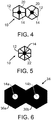
- Each of the one or more of the plurality of predefined line patterns can include a symmetrical cross, such as a symmetrical cross line pattern shown in FIG. 4 .
- Each of the one or more of the plurality of predefined line patterns can include a symmetric star, such as the symmetric star line pattern shown in FIG. 5 .
- Each of the one or more of the plurality of predefined line patterns can include a curved line pattern as shown in FIG. 18 .
- a decoding cell can indicate an encoding scheme used to encode a binary identifier.
- a decoding cell can indicate an encoding scheme that uses eight cell states to represent a predetermined sequence of three bits.
- a decoding cell can indicate an encoding scheme that uses coloured cells to represent a predetermined sequence of two or more bits.
- a decoding cell can indicate a variety of decoding instructions.
- a decoding instruction can include a start-of-row instruction that indicates a cell is the first cell in a cell array row (i.e., a row of the cell array).
- a computing device can determine that an encoded cell adjacent to the decoding cell in that row is the first cell of the cell array that can be decoded in order to recover a binary identifier.
- a decoding instruction can include an end-of-row instruction that indicates a cell is the last cell in a cell array row.
- a computing device can determine that an encoded cell adjacent to the decoding cell including the end-of-row instruction is the last cell in that row to decode in order to recover the binary identifier.
- a decoding instruction can include an end-of-array instruction that a computing device can use to determine there are no additional cells in the cell array to scan or decode.
- FIG. 2 shows eight instances of encoded cell 10 including a perimeter 12, an alignment mark 14 within perimeter 12, and a line pattern 17 within perimeter 12.
- the perimeters and alignment marks in these encoded cells can be identical.
- Each line pattern 17 shown in FIG. 2 is located at a different number of degrees from a given reference angle.
- Each encoded cell 10 shown in FIG. 2 includes a distinct line pattern 17 extending from an alignment mark to perimeter.
- the line patterns 17 are examples of asymmetrical radial lines, which can be referred to as "asymmetrical radial vectors" or "asymmetrical line patterns.”
- an asymmetrical radial line within a cell can be configured within one of the following example arrangements: (i) the asymmetrical radial line extends away from an alignment mark to a point short of perimeter, (ii) the asymmetrical radial line extends away from a perimeter to a point short of an alignment mark, and (iii) the asymmetrical radial line extends between a perimeter and an alignment mark without contacting either of the perimeter and the alignment mark.
- an asymmetrical line pattern (e.g., an asymmetrical radial line) of a cell can be aligned in any one of eight possible directions in angular increments of 45° from a given reference direction, namely at angular positions of 0°, 45°, 90°, 135°, 180°, 225°, 270° and 315° from the reference direction, as shown in FIG. 2 .
- the asymmetrical line patterns 17, as an attribute of cell 10 define an additional eight states (e.g., states #2 to #9) of cell 10. On their own, these additional eight states can represent three bits of embedded binary data, as illustrated in Table 1.
- Cell 10 can include another type of line pattern in the form of a diametrical (i.e. symmetrically opposing) vector 18 passing through alignment mark 14, as illustrated in FIG. 3 .
- a diametrical vector can be referred to as a "diametrical line pattern.”
- diametrical vectors 18 may be aligned in any one of four possible directions in angular increments of 45° from a given reference direction, namely at angular positions of 0°, 45°, 90°, and 135° from the reference direction, as shown in FIG. 3 .
- diametrical vectors 18 as a further attribute of cell 10 defines an additional four states (e.g., states #10 to #13) of cell 10, which, on their own, can represent two bits of embedded information, as illustrated in Table 2.
- Table 2 State Angular Position Binary Data #10 0° 00 #11 45° 01 #12 90° 10 #13 135° 11
- the angular increments from a given reference direction for diametrical vectors can be other than 45° so as to provide a different number of cell states corresponding to a set of diametrical vectors.
- Diametrical vectors 68 passing through an alignment mark are also shown in FIG. 11 .
- Cell 10 can include another type of line pattern in the form of a symmetric cross 20 centred at alignment mark 14, as illustrated in FIG. 4 .
- a symmetric cross can be referred to a "symmetric cross line pattern.”
- symmetric cross 20 may be aligned in either of two possible directions in angular increments of 45° from a given reference direction, at angular positions of 0° or 45° from the reference direction.
- the addition of the symmetric cross 20 as another attribute of cell 10 defines another two states (e.g., states #14 and #15) of cell 10 which, on their own, can represent a single bit of embedded information, as illustrated in Table 3.
- an angular increment from a given reference direction for symmetric crosses can be other than 45° so as to provide a different number of cell states using a set of symmetric crosses.
- Symmetric crosses 59 passing through an alignment mark are also shown in FIG. 11 .
- Cell 10 can include another type of line pattern in the form of a symmetrical star 22 centred on the alignment mark 14, as illustrated in FIG. 5 .
- a symmetric star 55 passing through an alignment mark is also shown in FIG. 11 .
- the use of symmetrical star 22 as another attribute of cell 10 defines an additional state (e.g., state #16) which, together with the empty-cell line 16 can represent a single bit of embedded information, as illustrated in Table 4.
- the different types of line patterns shown in FIG. 1 to FIG. 5 do not have to be used in isolation from each other or other line patterns.
- Each example line pattern illustrated in FIG. 2 to FIG. 5 includes at least one line within perimeter 12.
- a line is a continuous mark.
- the line patterns shown in FIG. 2 to FIG. 5 are straight lines, but the example embodiments are not so limited.
- FIG. 18 illustrates twelve example line patterns using curved lines. In particular, FIG. 18 shows twelve cells 10 including perimeter 12, alignment mark 14 within perimeter 12, and one of line patterns 91, 93, 95 and 97 within perimeter 12. Each of the line patterns shown in FIG. 18 can correspond to a distinct cell state.
- Each line pattern 91 extends between two distinct locations (separated by N 1 degrees) on perimeter 12 and is tangential to alignment mark 14.
- Line pattern 91 can be referred to as a "single curved tangential line pattern.”
- Each line pattern 93 includes two curved lines that extend between two distinct locations (separated by N 2 degrees) on perimeter 12 and that are tangential to alignment mark 14.
- Line pattern 93 can be referred to as a "dual curved tangential line pattern.”
- a person skilled in the art will understand that three or more curved lines tangential to alignment mark 14 and extending between two distinct locations on perimeter 12 could be included within a cell to provide additional cell states.
- a line pattern with two more curved lines tangential to alignment mark 14 and extending between two distinct locations on perimeter 12 can be referred to as a "multiple curved tangential line pattern.”
- Each line pattern 95 includes a single curved line that extends between two distinct locations (separated by N 3 degrees) on perimeter 12 and that passes through alignment mark 14.
- each line pattern 97 includes a single curved line that extends between two distinct locations (separated by N 4 degrees) on perimeter 12 and that passes through alignment mark 14.
- Line patterns 95 and 97 can be referred to as a "single curved pass-through line pattern.”
- two or more curved lines passing through alignment mark 14 and extending between two distinct locations on perimeter 12 could be included within a cell to provide additional cell states.
- a line pattern with two more curved lines passing through alignment mark 14 and extending between two distinct locations on perimeter 12 can be referred to as a "multiple curved pass-through line pattern.”
- One or more of N 1 , N 2 , N 3 , and N 4 can be 90°, 120°, 180° or another number of degrees.
- a line whether it is straight or curved is a continuous mark.
- a broken line is a non-continuous line, and is commonly referred to as a "dashed line.” Any line pattern described herein or shown in the figures can be used with a broken line instead of a line (i.e., a continuous mark).
- a perimeter of a cell such as perimeter 12, can be configured to have a predetermined width referred to herein as a "perimeter width.”
- a line of a line pattern can be configured to have a predetermined width referred to herein as a "line width.”
- the perimeter width for one or more cells in a cell array can be equal to the line width for those same one or more cells.
- the perimeter width and line width for a given cell can each equal 1 unit, 1.5 units, 2 units, 2.4 units, 3 units, or some other number of units. Units can, for example, be millimetres, centimetres, inches or some other units appropriate for measuring the width of an object.
- the perimeter width for one or more cells in a cell array can be equal to the line width times a first width multiplier (i.e., a positive decimal greater than 1.0 or less than 1.0). Accordingly, the line width for those one or more cells in a cell array can be equal to the perimeter width times a second width multiplier that equals 1 divided by the first width multiplier.
- the perimeter width for a given cell can equal 1 unit, 1.5 units, 2 units, 2.4 units, 3 units, or some other number of units, and the line width for the given cell can equal the 1 unit, 1.5 units, 2 units, 2.4 units, 3 units, or some other number of units times the second width multiplier.
- An encoded cell such as cell 10 can also include a colour attribute.
- the cell colours may comprise Black and the primary detectable colours of the visible spectrum, namely Red, Yellow, Green, Cyan, Blue, Magenta and Orange, i.e. a total of eight colours.
- These eight colour attributes can define an additional eight states of the encoded cell. On their own, these additional eight states can encode three bits of binary data, as illustrated in Table 6.
- a colour in Table 6 can be replaced by another colour.
- Magenta can be replaced with Violet or another colour.
- the colour attribute of an encoded cell can be used to augment the data capacity of the cell.
- the colour of an encoded cell may be used to represent precursor data to the binary data represented by the line pattern of the cell.
- the colour of encoded cell 10 may be used to represent the most significant bits of a concatenation with the binary data represented by the line pattern.
- a blue encoded cell with cell state #5 representing binary data 011 (as illustrated by data in Table 1) will yield a concatenated bit pattern of the binary data 101011.
- the binary data represented by the line pattern can be used to represent the most significant bits of a concatenation with the binary data represented by the cell colour.
- a concatenated bit pattern of for this alternative arrangement would be the binary data 011101.
- the colour attribute can also be used with a number of cell states other than the eight cell states identified in Table 2.
- each of the 16 possible states of encoded cell 10 illustrated in FIG. 1 to FIG. 5 can be displayed or printed in any of the 8 colours identified in Table 6.
- the 16 cell states (i.e., states #1 to #16) of encoded cell 10 and the cell colours (colours #1 to #8) of encoded cell 10 can be used to encode 7 bits of binary data, which is equivalent to octal (base 8) numbers ranging from the octal data 000 to the octal data 177, inclusive.
- This encoding scheme can, for example, be used to represent characters in a typical ASCII table with 128 characters.
- Table 7 shows an example in which the colour of each encoded cell can represent three most significant bits of the binary data and the cell states #1 to #16 can represent the least significant bits of the binary data.
- Other examples of using the cell states and cell colours to represent binary data or a range of octal numbers are also possible.
- an encoded cell 10 shown in FIG. 1 to FIG. 5 it can be important for the encoded cell to be scanned (i.e. "read") and decoded successfully and reliably. If encoded cell 10 is noisy, the possibility of erroneous scanning and decoding increases. A noisy cell can arise, for example, if it is printed by a poor quality printer or displayed on a low-resolution display device.
- the various states of encoded cells 10 shown in FIG. 1 to FIG. 5 exhibit different degrees of fault tolerance (or "noise tolerance"), i.e. the ability to be reliably scanned and decoded in the presence of noise.
- the most fault tolerant set of encoded cell states can be the set of eight cell states #2 to #9 illustrated in FIG. 2 .
- this level of noise tolerance will be referred to as Level I noise tolerance.
- the line pattern 17 in each of these Level I states is asymmetric in nature and, as a result, a noisy cell in each one of these states can be read or decoded with least probability of error.
- the next most noise tolerant set of encoded cell states can be the set of four cell states #10 to #13 illustrated in FIG. 3 , in which the diametrical line pattern 18 in each of these states is symmetrical.
- This level of noise tolerance will be referred to as Level II noise tolerance.
- a noisy Level I cell state it can be possible for a noisy Level I cell state to be erroneously scanned and decoded as a Level II cell state.
- Level III noise tolerance Less fault tolerance still can be the set of two encoded cell states #14 and #15 illustrated in FIG. 4 (referred to as level III noise tolerance), and least fault tolerant of all (for the 16 cell states of FIG.1 to FIG. 5 ) can be the set comprising the cell state #16 of FIG. 5 and the empty cell (state #1) of FIG. 1 (referred to as level IV noise tolerance).
- a "high definition" encoded cell that contains little or no noise may use all 16 possible cell states (i.e., states #1 to #16, which are the Level I, II, III and IV sets of encoded cell states).
- states #1 to #16, which are the Level I, II, III and IV sets of encoded cell states can encode 4 bits of binary data, as shown in Table 5.
- an encoded cell is noisy, it may use only the 8 line patterns for cell states #2 to #9 with Level I noise tolerance. In so doing, without consideration of cell colour, each encoded cell 10 would be able to encode three bits of binary data, as shown in Table 1. Thus, there can be a trade-off between encoded cell capacity and encoded cell noise.
- FIG. 1 and FIG. 3 to FIG. 5 illustrate instances of encoded cell 10 that have symmetrical line patterns.
- FIG. 2 illustrates use of a single asymmetrical line pattern 17 in each instance of encoded cell 10.
- Encoded cell 10 is not limited to the instances of asymmetrical line patterns shown in FIG. 2 .
- encoded cell 10 can include a line pattern with two or more lines arranged asymmetrically.
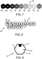
- FIG. 8 illustrates a cell array 80 including twelve instances of cell 10 including asymmetrical line patterns 82.
- each cell 10 includes an asymmetrical line pattern 82 with a pair of lines separated by 90 degrees, when considering the least amount of degrees separating the pair of lines.
- the lines of asymmetrical line patterns 82 of cell array 80 may be aligned in any one of twelve pairs of possible directions in angular increments of 30° from a given reference direction, namely at angular positions of 0° and 90°, 30° and 120°, 60° and 150°, 90° and 180°, 120° and 210°, 150° and 240°, 180° and 270°, 210° and 300°, 240° and 330°, 270° and 0°, 300° and 30°, and 330° and 60° from the reference direction, as shown in FIG. 8 (starting with the left most top cell and moving left to right in each row).
- An encoded cell 10 with an asymmetrical line pattern, such as asymmetrical line patterns 82 can be Level II noise tolerant.
- the encoded cells 10 shown in FIG. 8 can be defined as additional states of encoded cell 10. Staring in the top row, moving from left to right in each row in FIG. 8 , the encoded cells can be defined to have cell states #17 to #28. Various attributes can be associated with cell states #17 to #28. For example, Table 8 shows cell states #17 to #24 can be associated with 3 bits of binary data, and cell states #25 to #28 can be associated with decoding instructions for use by a computing device (e.g., a scanner or decoder) scanning a cell array. In an alternative arrangement, one or more of cell states #17 to #28 can be associated with a decoding instruction indicating a start of a cell array row or a start of a cell array.
- a computing device e.g., a scanner or decoder
- Such decoding cells can be used with a cell array using different cell colours or with an encoded cell using a single cell colour.
- Table 9 State Binary Data #2 0000 #3 0001 #4 0010 #5 0011 #6 0100 #7 0101 #8 0110 #9 0111 #17 1000 #18 1001 #19 1010 #20 1011 #21 1100 #22 1101 #23 1110 #24 1111
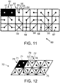
- FIG. 9 illustrates an alternative version of an encoded cell 15 with an empty-cell line pattern.
- encoded cell 15 includes a perimeter 19, an alignment mark 17 within perimeter 19, and a line pattern 13 within perimeter 19.
- Alignment mark 17 is an offset alignment mark that can be offset from a centre of encoded cell 15 or that is within an encoded cell that does not include a defined centre.
- Alignment mark 17 may be represented as a quadrilateral (e.g., a rectangle), as shown in FIG. 2 , but is not so limited.
- Alignment marks 14 and 17, shown in FIG. 1 and FIG. 9 , respectively, are shown as filled alignment marks, but an alignment mark of an encoded cell can, alternatively, be an unfilled alignment mark or a partially-filled mark.
- an alignment mark can be represented as a shape other than a circle or a quadrilateral, such as a triangle, a pentagon, a hexagon, an octagon, or some other shape.
- Cell arrays can be arranged in a variety of configurations. In one respect, a cell array can be arranged in a configuration in which all of the cells (and the cell perimeters) are the same shape.
- Cell array 30 shown in FIG. 10 is an example of a cell array in which all of the cells are the same shape.
- a cell array can be arranged in a configuration in which the cell array includes at least two different shaped cells (and perimeters).
- FIG. 20 shows a cell array 101 or a portion of cell array that includes triangle shaped cells 105 and square shaped cells 107.
- Triangle shaped cells 105 can be configured like triangle shaped cells 77 discussed with respect to FIG. 12
- square shaped cells 107 can be configured like rectangular shaped cells discussed with respect to FIG. 11 .
- Other examples of a cell array including at least two different shaped cells are also possible.
- a cell array can include non-cellular space between multiple cells that abut one another.
- FIG. 20 illustrates non-cellular spaces 103 between multiple cells of cell array 101. If a cell array with non-cellular space between adjacent cells in the cell array is acceptable or preferred, then the cell array can include cells with perimeters having curved lines, such as, but not limited to a circular perimeter, an oval perimeter, or an elliptical perimeter.
- a cell array can include multiple cells that are closely packed together without any non-cellular spaces and without any gaps.
- FIG. 19 illustrates a cell array 113 including multiple cross-shaped cells 115 that are closely packed together without any non-cellular spaces and without any gaps.
- a cell array can include a set of closely-packed cells arranged in a specific pattern depicting a desired shape, logo, configuration or the like.
- FIG. 10 illustrates a cell array 30.
- Cell array 30 includes a plurality of cells 10 grouped together in a closely-packed arrangement, similar to that of a honeycomb.
- Cell array 30 includes a plurality of hexagonal-shaped cells arranged as the letter "Z".
- Non-hexagonal shaped encoded cells can also be grouped together closely-packed, or otherwise, to form a cell array arranged as the letter "Z" or otherwise.
- Cell array 30 includes an alignment node 31, and 191 instances of cell 10. For clarity of FIG. 10 , only one instance of cell 10 is labeled and each instance of cell 10 is shown with the empty-cell line pattern 16. A person skilled in the art will understand that each cell 10 within cell array 30 can include any of the described line patterns or another line pattern. Alignment node 31 includes two adjacent null cells 32. In an alternative arrangement, cell array 30 could be configured with alignment node 38 as shown in FIG. 7 .
- Cell array 30 includes a first portion 35, a second portion 37, and a gap 39 separating first portion 35 and second portion 37.
- Alignment node 31 and encoded cells 10 of first portion 35 can be a first colour, such as cyan.
- the encoded cells 10 of second portion 37 can be a second colour, such as navy blue.
- a cell array can include more or fewer gaps separating distinct portions of the cell array.
- Each separate portion of a cell array can include an alignment node for that portion of the cell array.
- a separate portion, such as second portion 37 may not include an alignment node.
- a machine such as machine 212 shown in FIG. 13
- can be configured to generate gap 39 with a known dimension e.g., a known width, such as a width of cell 10 within cell array 30
- a machine e.g., a machine configured to decode cells and cell arrays
- a distance between distinct portions (e.g., the alignment marks 14) of two cells may be defined for a cell array. This distance may be referred to as a "pitch.”
- a cell array may be defined to have a standard pitch for adjacent encoded cells that abut one another and a maximum pitch for adjacent cells separated by a gap. The maximum pitch, for example, could equal the pitch times a pitch variable, such as 2.
- a machine e.g., a machine configured to scan or decode cells or a cell array
- An input including one or more encoding scheme selections can be provided to a machine for generating a cell array, such as cell array 30.
- the encoding scheme selections can include, but are not limited to, a colour selection for one or more encoded cells, a size of one or more encoded cells, one or more dimensions of the cell array (e.g., a height, length, or width), a shape of the cell array, a gap selection, and the data to be encoded within the encoded cells.
- a machine that generates a cell array can be configured to generate cell arrangement data, such as the example cell arrangement data shown in Table 10.
- the example cell arrangement data can indicate, for each cell in a cell array, one or more of the following items: a cell number, a cell position, a cell type, a cell state, and a cell colour.
- the indicator "***" indicates cell arrangement data for cell array 30 not included in Table 10.
- the cell positions can, for example, be specified by a row indicator and a position indicator.
- the left-most position in a row can be position 1, 1L or 1R.
- Position 1L indicates a position to the left of the first position in a preceding row.
- Position 1R indicates a position to the right of the first position in a preceding row.
- Table 10 indicates example cells types, cell states, and cell colours of cells that can be included within cell array 30. The cell type of cell number 9 is indicated as a gap for including gap 39 of cell array 30.
- Table 10 shows cell array 30 includes 198 cells. Those cells include 2 null cells 32, 191 cells 10, and 5 gap cells (i.e., 1 gap cell in each row of the top 5 rows.
- Table 10 Cell # Cell Position Cell Type Cell State Cell Colour 1 Row 1, Position 1 Alignment #1 N.A. #5 2 Row 1, Position 2 Alignment #2 N.A.
- Alignment node 31 of cell array 30 can indicate a first portion of cell array 30 to be scanned or a first portion of cell array 30 to be decoded. With cell array 30 arranged as shown in FIG. 10 , alignment node 31 is at a top and left side of cell array 30. Cell array 30 can, however, be rotated a number of degrees greater than 0° and a machine, such as machine 230, can still use alignment node 31 to determine a start point for scanning and decoding cell array 30.
- FIG. 6 illustrates an alignment node 34 that may be used in conjunction with a cell array composed of cells without a colour attribute.
- Alignment node 34 can be a starting node or an ending node.
- Alignment node 34 can include two identical, adjacent alignment cells 36a and 36b.
- a cell body of alignment cells 36a and 36b can be the inverse of the cell body of a cell 10 with an empty-cell line pattern 16, as shown in FIG. 1 .
- alignment marks 14a, 14b at the centre of alignment cells 36a and 36b are white instead of black, and the other portions of the cell body within the perimeter of alignment cells 36a and 36b are totally black instead of white.
- At least one of the cell bodies within alignment cells 36a and 36b can be a colour other than black or white.
- an alignment cell such as alignment cells 36a and 36b
- a null cell For convenience, an alignment cell, such as alignment cells 36a and 36b, can be referred to as a null cell.
- the machine can use alignment mark 14a to locate a centre of the first alignment cell 36a, and the distance between alignment marks 14a and 14b of the adjacent alignment cells to determine the pitch between adjacent encoded cells of a cell array, such as cell array 30, or to determine a maximum pitch by multiplying the detected pitch by a pitch variable.
- FIG. 7 illustrates an alignment node 38 for a cell array including a colour attribute.
- the alignment node 38 includes an ordered string of adjacent null cells, one in each permissible colour of encoded cell 10, with two adjacent instances of the leading null cell.
- the alignment node 38 includes a string of nine adjacent null cells in the following order: two black null cells 40a and 40b followed by one null cell in each of the following colours - Red 42, Yellow 44, Green 44, Cyan 46, Blue 50, Magenta 52 and Orange 54.
- the scanner may use the distance between the alignment marks of the black null cells 40a and 40b to determine the pitch between adjacent cells of a cell array. Furthermore, the scanner may use the predetermined order of the coloured null cells 42 to 54 to perform a colour calibration of the machine itself.
- a machine 230 may analyse a scanned alignment node to determine whether the cell array to which it applies is a monochrome encoded cell or whether it is composed of encoded cells 10 that have a colour attribute. For example, if the first two scanned encoded cells are null cells and the third cell is not a null cell, then the alignment node is as indicated by reference numeral 34 of FIG. 6 and the cell array to which the alignment node 34 pertains is to be treated as a monochrome encoded cell, irrespective of the colour or colours in which it is displayed. If, on the other hand the first two scanned encoded cells are null cells and so is the third, then the alignment node can be as indicated by reference numeral 38 of FIG. 7 and the cell array 30 can be composed of cells 10 that have a colour attribute.
- a scanning machine i.e., a scanner
- a set of encoded cells 10 at Level I noise tolerance that use only cell states #2 to #9, as illustrated in FIG. 2 , in monochrome, can encode 3 bits of binary data, as illustrated in Table 1.
- cell states #1 to #16, as illustrated in FIG. 1 to FIG. 5 can increase the encoded cell capacity to 4 bits of digital data, as illustrated in Table 5.
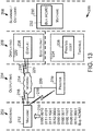
- FIG. 13 is a block diagram showing an example system 200 in accordance with an example embodiment.
- system 200 includes an encoding stage 202, an outputting stage 204, a displaying stage 206, and a scanning or decoding stage 208.
- System 200 can include a machine, such as a machine 212 or 230, a machine including a printer 216, or a machine including display 226.
- Each element shown in FIG. 13 is not restricted to operating within the stage 202, 204, 206, or 208 that includes that element.
- input 210 is provided to machine 212.
- Input 210 can include data to be encoded by machine 212.
- input 210 can include a binary identifier, such as the binary data "0100 0010 to 0010 0001" shown in FIG. 13 .
- the example binary identifier shown in FIG. 13 represents the ASCII values for the text "Buy ACME!
- Receiving a binary identifier can include receiving data that machine 212 can convert to binary data.
- machine 212 can receive hexadecimal equivalents for the binary data shown in FIG. 13 (i.e., the hexadecimal data 42, 75, 79, 20, 41, 43, 4D, 45, and 21) and convert the hexadecimal values to equivalent binary values.
- machine 212 can receive text, such as "Buy ACME! convert the text to ASCII values, and then convert the ASCII values to equivalent binary values.
- Input 210 can include one or more encoding scheme selections.
- An encoding scheme selection can, for example, include a cell shape selection, a cell colour selection, a cell array colour selection, or a layout selection for generating a cell array. Other examples of an encoding scheme selection are also possible.
- Machine 212 can encode a portion of input data 210 (e.g., the binary identifier portion of input data 210) as a cell array. Encoding a portion of input data 210 can include converting a portion of input data 210 based on an ASCII table. Converting the portion of input data 210 can include converting text, such as "Buy ACME!,” to the binary values equivalent to ASCII values representing the "Buy ACME! text. Machine 212 can encode the binary values obtained by converting the portion of input data 210 into a cell array based on an encoding scheme selection.
- Machine 212 can output (e.g., provide or transmit) a cell array to an element of outputting stage 204.
- Outputting a cell array can include outputting encoded cells of the cell array one at a time or two or more at a time.
- Outputting a cell array or an encoded cell can include outputting data indicating the cell array or encoded cell, respectively.
- Outputting stage 204 can include elements such as network 214 and printer 216.
- Outputting the data indicating the cell array can include transmitting an encoding scheme 268 or encoding scheme data.
- Outputting the data indicating the cell array can include transmitting a data representation of a cell of the cell array.
- Machine 212 can provide the cell array (or the data indicating the cell array) to network 214 and printer 216 over a wireless communication link 218 or a wired communication link 220.
- Wireless communication link 218 can be configured according to any of a variety of wireless communication protocols, such as an IEEE 802.11 protocol, such as the protocol commonly referred to as Wi-Fi.
- Wired communication link 220 can be configured according to any of a variety of wired communication protocols, such as the protocol commonly referred to as Ethernet.
- a communication link (not shown) can include both a wireless communication link and a wired communication link.
- Network 214 can include a local area network or a wide area network, such as the Internet.
- Network 214 can include wireless communication links 218 and wired communication links 220.
- Printer 216 can include a laser printer, a dot matrix printer, an inkjet printer, but is not so limited. Printer 216 can be configured to print an instance of an encoded cell or cell array on a surface of an article of manufacture.
- Displaying stage 206 can include an electronic segment 222 and a tangible segment 224.
- Electronic segment 222 can include a display 226.
- Network 214 can transport an encoded cell or a cell array (or the data indicating the encoded cell or cell array) to display 226 over a communication link, such as wireless communication link 218 or wired communication link 220.
- Display 226 can include any of a variety of electronic displays, such as, but not limited to, a light emitting diode (LED) display, a plasma display, a cathode ray tube (CRT) display, or a liquid crystal display (LCD).
- Display 226 can include a display within a kiosk, such as a kiosk at a shopping mall, airport, or a museum.
- Display 226, which can be referred to as a "display device,” can be embodied within a machine, such as a machine 248 shown in FIG. 14 .
- Displaying an encoded cell or a cell array within displaying segment 206 can include providing a tangible instance of the encoded cell or a tangible instance of the cell array.
- the tangible instances of the encoded cell or cell array can be generated by printer 216 printing the encoded cell or cell array, or by another means, such as but not limited to painting, engraving, etching, dyeing, or silk printing.
- a tangible instance of an encoded cell or a cell array can be generated on a surface of an article of manufacture including any of a variety of media, such as but not limited to, paper, plastic, clothing, a metal, a ceramic material, or cardboard.
- Scanning or decoding stage 208 can include a machine 230 configured to scan an encoded cell or a cell array provided within displaying stage 206.
- Machine 230 can decode the cell or the cell array to recover the input data encoded into the encoded cell or the cell array, respectively. For example, machine 230 can recover the input text "Buy ACME! and provide the recovered data to a display 232 for displaying the recovered data. Additional details regarding aspects shown in FIG. 13 are described elsewhere in this description.
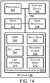
- FIG. 14 is a block diagram of an example machine 248.
- machines 212 and 230 can be arranged like machine 248 or a portion thereof.
- machine 248 can include a processor 250, a data transceiver 252, a user interface 254, a computer-readable medium 256, and a capture device 266, all of which may be coupled together by a system bus, network, or other connection mechanism 258.
- Machine 248 can comprise a smartphone or a tablet device, but is not so limited.
- a processor such as processor 250, can comprise one or more general purpose processors (e.g., INTEL single core microprocessors or INTEL multicore microprocessors) or one or more special purpose processors (e.g., digital signal processors).
- a processor can be configured to execute computer-readable program instructions (CRPI) stored in a data storage device (e.g., a memory).
- CRPI computer-readable program instructions
- a processor can be referred to as a computing device or a computer-readable processor.
- Data transceiver 252 can include one or more transmitters (e.g., a wireless communication link transmitter or a wired communication link transmitter).
- a wireless communication link transmitter can be configured to transmit data to or over a wireless communication link.
- a wired communication link transmitter can be configured to transmit data to or over a wired communication link.
- Data transceiver 252 can include one or more receivers (e.g., a wireless communication link receiver or a wired communication link receiver).
- a wireless communication link receiver can be configured to receive data transmitted over or by a wireless communication link.
- a wired communication link receiver can be configured to receive data transmitted over or by a wired communication link.
- Data transceiver 252 can include one or more antennas, such as one or more antennas connected to a wireless communication link transmitter or a wireless communication link receiver.
- Data transceiver 252 can include a network interface card configure to interface with a wired communication link, such as wired communication link 220.
- Data transceiver 252 can be configured to receive an input, such as input data 210.
- Data transceiver 252 can be configured to transmit an encoded cell or a cell array (or data indicating the encoded cell or cell array) to an element in outputting stage 204, such as network 214 or printer 216.
- User interface 254 can include one or more input components for inputting data, such as input data 210, into machine 248.
- user interface 254 can be configured to receive an input request to cause the computing device to scan or decode a cell array.
- the input request can be a scan request, a decode request or another request.
- the one or more input components can include, but is not limited to, a computer keyboard, a touch screen display, a computer mouse or other pointing device, or an audio microphone.
- User interface 254 can include one or more output components for presenting data, such as a cell array, to a user.
- the one or more output components can include, but is not limited to, a display (such as an LED, an LCD, a CRT display, or plasma display) or an audio speaker.
- a display such as an LED, an LCD, a CRT display, or plasma display
- One or more components, such as the touch screen display can function as an input component and an output component.
- Capture device 266 comprises one or more components configured to capture a cell array, such as cell array 30.
- a component configured to capture a cell array includes a digital camera configured to capture an image of the cell array or to scan an image of the cell array.
- Capture device 266 can use a quantity of dots per inch (DPI) to store a representation of the cell array (i.e., the captured cell array).
- DPI dots per inch
- the specified DPI can indicate the noise level of encoded cells that can be accurately decoded by machine 248.
- capture device 266 can capture individual cells of the cell array.
- Capture device 266 can comprise a camera within a smartphone or tablet device, but is not so limited.
- Computer-readable medium 256 can comprise a non-transitory computer-readable storage medium readable by a processor, such as processor 250.
- the computer-readable storage medium can comprise volatile and/or non-volatile storage components, such as optical, magnetic, organic or other memory or disc storage, which can be integrated in whole or in part with a processor.
- Computer-readable medium 256 may also or alternatively be provided separately, as a non-transitory machine readable medium.
- computer-readable medium 256 can comprise a transitory computer-readable medium.
- the transitory computer-readable medium can include, but is not limited to, a communications medium such as a digital or analogue communications medium (e.g., a fiber optic cable, a waveguide, a wired communication link, or a wireless communication line).
- a communications medium such as a digital or analogue communications medium (e.g., a fiber optic cable, a waveguide, a wired communication link, or a wireless communication line).
- Computer-readable medium 256 can store various data for use by machine 248 to carry out any functions described herein as being performed or performable by machine 212, 230, or 248.
- computer-readable medium 256 can store computer-readable program instructions (CRPI) 260, input data 262, a cell array 264, an encoding scheme 268, a set of line patterns 270, and a colour array 272.
- CRPI 260 can be written according to any of a variety of computer programming languages such as, but not limited to, the C and C++ programming languages.
- Input data 262 can include input data 210, including input data to be encoded into an encoded cell or a cell array.
- Input data 262 can include one or more encoding scheme selections.
- Cell array 264 can include one or more cell arrays as described herein.
- cell array 264 can include one or more cell arrays encoded by processor 250.
- machine 248 is used to decode a cell array
- cell array 264 can include one or more cell arrays captured by capture device 266.
- Cell array 264 can include one or more cell arrays encoded by processor 250 and one or more cells captured by capture device 266.
- Encoding scheme 268 can include one or more encoding schemes usable by processor 250 to encode a binary identifier or to decode a captured cell array.
- Encoding scheme 268 can include an encoding scheme that including encoding scheme data (ESD) that defines a cell array.
- ESD encoding scheme data
- the ESD can include data defining the cell shape(s) available for encoding cells in the cell array.
- the ESD can include data defining a pitch dimension.
- the ESD can include data defining a reference angle position.
- the ESD can include data defining which line patterns are available for encoding cells in the cell array. That ESD can include data defining how many line patterns are available for encoding cells in the cell array.
- the ESD can include data that represents a cell colour.
- the ESD can include data defining a predetermined sequence of bits corresponding to each available line pattern.
- the ESD can include data defining which cell colours are available for encoding cells in the cell array.
- the ESD can include data defining how many cell colours are available for encoding cells in the cell array.
- the ESD can include data defining a predetermined sequence of bits for each available cell colour.
- the ESD can include data defining a bit order for any cell encoding more than one predetermined sequence of bits.
- the ESD can include data defining one or more decoding cells available for placement in the cell array.
- the ESD can include data defining whether gaps cells are available for placement in the cell array.
- the ESD can include a data representation of a cell corresponding to each of the state numbers.
- the ESD can include data representation of a cell can include data that represents a line pattern of the cell to distinguish the cell from other cells.
- the ESD can define an alignment mark available for placement in a cell.
- the ESD can define an alignment mark position within a cell.
- Other examples of the ESD that can be included within an encoding scheme 268 are also possible.
- Line patterns 270 can comprise one or more sets of line patterns. Each set of line patterns can correspond to one or more encoding schemes. Computing device 250 can use a set of line patterns for comparing to a line pattern of a cell being decoded. A data representation used by encoding scheme 258 can be within line patterns 270.
- Colour array 272 can comprise one or more colour arrays. Each colour array 272 can correspond to one or more encoding schemes. Computing device 250 can use a colour array for comparing to a cell colour of a cell being decoded. The data representation used by encoding scheme 258 can be within colour array 272.
- Computer-readable medium 256 can comprise a computer-readable medium storing program instructions, that when executed by a computing device, such as processor 250, cause a set of functions to be performed.
- the set of functions can include the set of functions 150 described with respect to FIG. 15 , the set of functions 160 described with respect to FIG. 16 , or the set of functions 170 described with respect to FIG. 17 .
- the set of functions can describe any combination of functions described in the additional example embodiments numbered 1 to 36, 110 to 143, and 213 to 246.
- Machine 248, or elements thereof can be configured to cause a set of functions to be performed.
- Computer-readable medium 256 can store program instructions, such as CRPI 260, that when executed by processor 250, cause the set of functions to be performed.
- the functions can include the set of functions 150 described with respect to FIG. 15 , the set of functions 160 described with respect to FIG. 16 , or the set of functions 170 described with respect to FIG. 17 .
- the set of functions can describe any combination of functions described in the additional example embodiments numbered 1 to 36, 110 to 143, and 213 to 246.
- FIG. 15 depicts a flowchart showing a set of functions (e.g., operations) 150 (or more simply, "the set 150") that can be carried out in accordance with one or more of the example embodiments described herein.
- the functions of the set 150 are shown within blocks labeled with even integers between 152 and 158, inclusive. Any other function(s) described herein can be performed prior to, while, or after performing any one or more of the functions of the set 150. Those other function(s) can be performed in combination with or separately from any one or more of the functions of the set 150. Reference numbers from the figures are included with the following description of FIG. 15 for purposes of example rather than for limiting the description to any particular embodiment.
- Set 150 can include one or more additional functions. Examples of such additional functions are provided after the description of block 158. Other examples of such additional functions are also possible.
- CRPI 260 can include program instructions to perform any of the additional functions described with respect to at least one of set 150, set 160, and set 170.
- Block 152 includes receiving, by a computing device 250, a binary identifier comprising a plurality of bits.
- Receiving the binary identifier can include receiving data (e.g., input 210) that indicates each bit of the plurality of bits in a predetermined sequence.
- Computing device 250 can also receive a non-binary input and convert the non-binary input to the binary identifier.
- Receiving the binary identifier can include receiving the non-binary identifier and converting the non-binary identifier to an equivalent binary identifier.
- a non-binary identifier such as the hexadecimal data 45 is equivalent to the binary identifier comprising the binary data 0100 0101.
- the binary identifier or the non-binary identifier can, for example, include data representing a set of ASCII characters that indicate a string of text, such as "Buy ACME!
- block 154 includes determining, by computing device 250, one or more encoded cells that encode the binary identifier in accordance with an encoding scheme 268, wherein each encoded cell indicates a predetermined sequence of two or more bits, and wherein each encoded cell includes a perimeter, an alignment mark within the perimeter, and a line pattern within the perimeter.
- the perimeter can be configured as any perimeter described herein, but is not so limited.
- the alignment mark within the perimeter can be configured like any alignment mark described herein, but is not so limited.
- the line pattern within the perimeter can be configured as any line pattern described herein, but is not so limited.
- Determining the one or more encoded cells in accordance with an encoding scheme 268 can include determining, for each of the one or more encoded cells, a cell colour, such as a cell colour from a plurality of cell (e.g., the colours identified in Table 6 or a different plurality of colours). As shown in Table 6, each cell colour can represent a distinct sequence of binary data, such as two or more bits of data. In accordance with the example embodiments in which the encoding scheme 268 is based on a cell colour and a line pattern, two or more data bits represented by the cell colour can be a precursor to any data bit(s) represented by the line pattern.
- two or more data bits represented by a line pattern can be a precursor to any data bit(s) represented by a cell colour.
- determining a cell colour can include determining a cell colour associated with a predetermined sequence of two or more bits that matches the predetermined sequence of two or more bits indicated by the line pattern of the cell so as to encode redundant sequences of two or more bits in the encoded cell that can be compared during decoding of the encoded cell to confirm proper decoding.
- encoding scheme 268 can include an encoding scheme based on the data shown in Table 5 and the binary identifier can include the binary data of input 210 shown in FIG. 13 (i.e., 0100, 0010, 0111, 0101, 0111, 1001, 0010, 0000, 0100, 0001, 0100, 0011, 0100, 1101, 0100, 0101, 0010, and 0001).
- Encoding that binary identifier using the encoding scheme of Table 5 can include computing device 250 identifying each set of four data bits and determining the cell state number that corresponds to the four data bits. In accordance with this example, computing device 250 can determine the following cell state numbers: 5, 3, 8, 6, 8, 10, 3, 1, 5, 2, 5, 4, 5, 14, 5, 6, 3, and 2.
- Computing device 250 can select data (e.g., a line pattern or colour) representing a cell corresponding to each of the determined state numbers for use in generating a cell array. For other encoding schemes 268, computing device 250 can determine a cell state number that corresponds to a different number of data bits (e.g., 2, 3, 5, 6, 7, 8, or 16 bits).
- data e.g., a line pattern or colour
- computing device 250 can determine a cell state number that corresponds to a different number of data bits (e.g., 2, 3, 5, 6, 7, 8, or 16 bits).
- block 156 includes generating, by the computing device 250, a cell array 30 that includes the one or more encoded cells.
- Generating the cell array 30 can include the computing device 250 generating cell arrangement data for indicating a position for each cell in the cell array relative to a position of at least one other cell in the cell array.
- Computing device 250 can therefore determine a position for each cell (e.g., an encoded cell, an alignment cell, a gap, a decoding cell, or a layout cell) within the cell array.
- Computing device 250 can determine cells other than the encoded cells to include in the cell array based, at least in part, on the selected encoding scheme 268.
- the generated cell arrangement data can also identify one or more pitch dimensions to specify a pitch between two or more alignment marks in adjacent cells.
- the cell arrangement data can be stored in within computer-readable medium 256 as a cell array 264.
- block 158 includes outputting, by computing device 250, data for producing a graphical representation of the cell array.
- Outputting the data referenced in block 158 can include transmitting the data from computing device 250 to network 214 for transmission, in turn, to another machine.
- the other machine can include printer 216, which can, in turn, print an instance of the graphical representation of the cell array on the surface of an article of manufacture.
- the other machine can include an engraving machine (e.g., a laser engraving machine) which can, in turn, engrave an instance of the graphical representation of the cell array on the surface of an article of manufacture.
- the other machine can include a machine comprising display 226, which can, in turn, display that data as a graphical representation of the cell array.
- a computing device e.g., processor 250
- a machine such as machine 248
- receiving the binary identifier at block 152, determining the one or more cell arrays at block 154, generating the cell array at block 156, and outputting the data at block 156 can be carried out by the machine (i.e., a machine that embodies the computing device).
- the determined one or more alignment cells can include any one or more of the following: (i) at least one alignment cell that indicates a start point within the cell array, (ii) two or more adjacent cells (e.g., cells 36a and 36b) that collectively identify a starting node (e.g., starting node 34) in the cell array, (iii) at least one alignment cell that indicates an end point within the cell array, (iv) at least one alignment cell that indicates an end point of a row within the cell array, (v) a plurality of coloured alignment cells, and (vi) at least one alignment cell that is an inverse of an empty-cell line pattern, such as the empty-cell line pattern of encoded cell 10 shown in FIG. 1 .
- a coloured alignment cell can be coloured to match a corresponding colour of a plurality of colours, such as the plurality of colours identified in
- Another function that can be performed as part of the set 150 includes determining, by computing device 250, a layout selection for generating the cell array 30, and determining, by computing device 250, a layout in accordance with the determined layout selection.
- Generating the cell array 30 can include positioning the one or more encoded cells in the layout in accordance with the determined layout selection.
- Generating cell array 30 can include positioning one or more layout cells.
- the one or more layout cells can form a portion of the layout but do not encode any portion of the binary identifier.
- the noise tolerance level can be selected from among the noise tolerance levels described herein (i.e. Noise Tolerance Levels I, II, III, and IV) or from among another set of noise tolerance levels that can be defined.
- the one or more encoded cells in the cell array can have a noise tolerance level that is more noise tolerant or that matches the selected noise tolerance level.
- FIG. 16 depicts a flowchart showing a set of functions (e.g., operations) 160 (or more simply, "the set 160") that can be carried out in accordance with one or more of the example embodiments described herein.
- the functions of the set 160 are shown within blocks labeled with even integers between 162 and 168, inclusive. Any other function(s) described herein can be performed prior to, while, or after performing any one or more of the functions of the set 160. Those other function(s) can be performed in combination with or separately from any one or more of the functions of the set 160. Reference numbers from the figures are included within the following description of FIG. 16 for purposes of example rather than for limiting the description to any particular embodiment.
- Set 160 can include one or more additional functions. Examples of such additional functions are provided after the description of block 168. Other examples of such additional functions are also possible.
- Block 162 includes receiving, by a computing device 250, a captured cell array including one or more encoded cells that encode a binary identifier in accordance with an encoding scheme 268, wherein each encoded cell 10 indicates a predetermined sequence of two or more bits, and wherein each encoded cell includes a perimeter, an alignment mark within the perimeter, and a line pattern within the perimeter.
- the perimeter can be configured as any perimeter described herein, but is not so limited.
- the alignment mark within the perimeter can be configured like any alignment mark described herein, but is not so limited.
- the line pattern within the perimeter can be configured as any line pattern described herein, but is not so limited.
- the computing device 250 can receive the captured cell array from various components, such as data transceiver 252, computer-readable medium 256, capture device 266, or another component configured to provide the captured cell array to the computing device.
- Receiving the captured cell array can include receiving a captured image of the cell array or receiving a scanned image of the cell array.
- the captured cell array can include at least one decoding cell that includes a decoding instruction (e.g., a decoding instruction that indicates the encoding scheme 268 used to encode the binary identifier).
- block 164 includes decoding, by computing device 250, each encoded cell 10 in the captured cell array 30 in accordance with a decoding scheme corresponding to the encoding scheme to recover the bits indicated by the encoded cell.
- Decoding each encoded cell in the capture cell array can include, but is not limited to, performing any one or more of following functions: (i) detecting, by the computing device, each encoded cell in the captured cell array, and (ii) decoding, by the computing device, a cell colour for each cell of the one or more encoded cells in the cell array.
- the decoded colour can be one of the colours identified in Table 6.
- Each colour of the plurality of colours can represent a distinct sequence of two or more bits.
- Decoding an encoded cell can also include computing device 250 identifying the line pattern within the encoded cell 10.
- Computing device 250 can identify an alignment node 31 of cell array 30 regardless of where alignment node 31 is positioned within the capture cell array.
- alignment node 31 within the capture cell array 30 could be located at a top left portion of cell array 30 as shown in FIG. 10 .
- alignment node 31 within the captured cell array could be located at a top right position of cell array 30 with one null cell 32 above the other null cell 32. This can be visualized by rotating FIG. 10 clockwise 90 degrees.
- alignment node 31 within the captured cell array could be located at a lower right position of cell array 30. This can be visualized by rotating FIG. 10 clockwise 180 degrees.
- Computing device 250 can determine the pitch between alignment marks in the first two cells of an alignment node. Computing device 250 can use the determined pitch to locate an alignment mark in a cell to be decoded (e.g., a cell adjacent to an alignment cell or a cell adjacent to a previously decoded cell). Computing device 250 can use the determined pitch to determine the perimeter of the cell to be decoded. Computing device 250 can compare a line pattern within the determined perimeter of the cell being decoded to a set of line patterns 270. Computing device 250 can determine a line pattern within the set of line patterns 270 that matches the line pattern of the cell being decoded in order to determine the state number or bit sequence encoded by the cell being decoded.
- block 166 includes recovering, by computing device 250, the binary identifier by combining the recovered bits.
- Combining the recovered bits can include combining the bits recovered for each cell into a predetermined sequence of bits and then combining the predetermined sequence of bits for each cell according to an order that the cells occur in the cell array.
- the predetermined sequence can include two or more bits including two or more bits based on the line pattern within the perimeter of the cell and two or more bits represented by the cell colour.
- the two or more bits represented by the cell colour can be a precursor to the two or more bits based on the line pattern.
- the two or more bits based on the line pattern can be a precursor to the two or more bits represented by the cell colour.
- block 168 includes outputting, by computing device 250, the recovered binary identifier.
- Outputting the recovered binary identifier can include a machine, including the computing device and a display, displaying the recovered binary identifier on the display.
- Outputting the recovered binary identifier can include transmitting the recovered binary identifier from the computing device to a display device, such as a display device of user interface 254.
- Another function that can be performed as part of the set 160 includes identifying, by the computing device, one or more alignment cells within the captured cell array. Identifying each alignment cell can include identifying a null cell, such as null cell 36a or 36b. Identifying the null cell can include identifying, by the computing device within the captured image, a perimeter and an alignment mark within the perimeter.
- the identified one or more alignment cells can include any one or more of the following: (i) at least one alignment cells that indicates a start point within the cell array, (ii) an alignment node including two or more adjacent alignment cells that collectively identify a start point within the cell array, (iii) at least one alignment cell that indicates an end point within the cell array, (iv) at least one alignment cell that indicates an end point of a row within the cell array, (v) a plurality of coloured alignment cells, each coloured alignment cell comprises an alignment cell coloured to match a corresponding colour of a plurality of colours, and (vi) at least one alignment cell that is an inverse of an empty-cell line pattern.
- Another function that can be performed as part of the set 160 includes determining, by the computing device, a dimension of distance from a portion of the perimeter, such as an outer edge of the perimeter, of the null cell to some portion of the alignment mark, such as the centre of the alignment mark.
- Computing device 250 can use the dimension to determine a pitch between adjacent cells in the cell array. As an example, computing device 250 can multiply the dimension by two to determine the pitch.
- Identifying the one or more alignment cells can include computing device 250 determining whether any other alignment cell is adjacent to an identified alignment cell by searching for another alignment mark located within a distance equal to the determined pitch relative to a location of the identified alignment cell. Upon locating another alignment cell, computing device 250 can determine whether the cell including the located alignment cell is a null cell.
- Another function that can be performed as part of the set 160 includes determining, by the computing device, a distance between alignment marks within two adjacent alignment cells, and determining, by the computing device, presence of an encoded cell in the captured cell array by detecting an alignment mark of the encoded cell in the captured cell array and an alignment mark of another captured cell array being separated by a distance equal to the distance between alignment marks within two adjacent cells.
- Another function that can be performed as part of the set 160 includes converting, by the computing device, the recovered binary identifier to an alphanumeric representation of the recovered binary identifier.
- outputting the recovered binary identifier can include transmitting the alpha-numeric representation to a printer or display device.
- the alpha-numeric representation for input 210 can be "Buy ACME! as shown in FIG. 13 .
- FIG. 17 depicts a flowchart showing a set of functions (e.g., operations) 170 (or more simply, "the set 170") that can be carried out in accordance with one or more of the example embodiments described herein.
- the functions of the set 170 are shown within blocks labeled with even integers between 172 and 174, inclusive. Any other function(s) described herein can be performed prior to, while, or after performing any one or more of the functions of the set 170. Those other function(s) can be performed in combination with or separately from any one or more of the functions of the set 170. Reference numbers from the figures are included within the following description of FIG. 170 for purposes of example rather than for limiting the description to any particular embodiment.
- Set 170 can include one or more additional functions. Examples of such additional functions are provided after the description of block 174. Other examples of such additional functions are also possible.
- Block 172 includes receiving, by a computing device, data specifying a cell array, wherein the cell array includes one or more encoded cells that encode a binary identifier in accordance with an encoding scheme, wherein each encoded cell indicates a predetermined sequence of two or more bits, and wherein each encoded cell includes a perimeter, an alignment mark within the perimeter, and a line pattern within the perimeter.
- the received data can indicate a cell colour for each of the one or more encoded cells. Each cell colour can represent a distinct sequence of two or more bits.
- the received data can indicate a cell colour for any other cells within the specified cell array.
- the perimeter can be configured as any perimeter described herein, but is not so limited.
- the alignment mark within the perimeter can be configured like any alignment mark described herein, but is not so limited.
- the line pattern within the perimeter can be configured as any line pattern described herein, but is not so limited.
- block 174 includes displaying, by a display connected to the computing device, a graphical representation of the cell array, wherein the displayed cell array includes the one or more encoded cells that encode the binary identifier in accordance with the encoding scheme, wherein each displayed encoded cell indicates a predetermined sequence of two or more bits, and wherein each encoded cell includes a perimeter, an alignment mark within the perimeter, and a line pattern within the perimeter.
- the display can be connected to computing device 250 by at least one of a wireless communication link, a wired communication link, and a wired and wireless communication link.
- the predetermined sequence of two or more bits can include two or more bits based on the line pattern within the perimeter and two or more bits based on a cell colour.
- the two or more bits represented by the cell colour can be a precursor to the two or more bits based on the line pattern.
- the two or more bits represented by the line pattern can be a precursor to the two or more bits based on the cell colour.
- the distinct sequence of two or more bits represented by the cell colour indicated for the cell can match the predetermined sequence of two or more bits indicated by the line pattern of the cell so as to encode redundant sequences of two or more bits in the encoded cell that can be compared during decoding of the encoded cell to confirm proper decoding.
- the cell array can include one or more alignment cells.
- the received data can indicate the one or more alignment cells within the cell array.
- the one or more alignment cells can include any of the following: (i) a plurality of coloured alignment cells, (ii) at least one alignment cell that indicates a start point within the cell array, (iii) an alignment node including two or more adjacent alignment cells that collectively identify a start point within the cell array, (iv) at least one alignment cell that indicates an end point within the cell array, (v) at least one alignment cell that indicates an end point of a row within the cell array, and (vi) at least one alignment cell that is an inverse of an empty-cell line pattern.
- the plurality of colours can include a predetermined number of colours.
- the two or more adjacent cells can include a predetermined number of cells equal to the predetermined number of colours. Each cell of the two or more adjacent cells can correspond to a distinct colour of the predetermined number of colours.
- Another function that can be performed as part of the set 170 includes receiving, by computing device 250, a non-binary identifier equivalent to the binary identifier, and converting, by computing device 250, the non-binary identifier to the binary identifier. Accordingly, receiving the binary identifier can include receiving the binary identifier converted by computing device 250 from the non-binary identifier.
- FIG. 15 to FIG. 17 refer to computing device 250 and machine 248.
- a separate instance of computing device 250 and machine 248 can be used to carry out one or more of the functions of the sets 150, 160, and 170, but is not necessary, as a single instance of computing device 250 or machine 248 can carry out one or more of the functions of the sets 150, 160, and 170.
- FIG. 11 illustrates an example cell array 60 including alignment node 61 and encoded cells 62.
- Alignment node 61 and encoded cells 62 are rectangular, and can be square. Alignment node 61 may include adjacent null cells 57, as shown in FIG. 11 .
- Encoded cells 62 include a rectangular perimeter (e.g., a square perimeter) 63, an alignment mark 65 within perimeter 63, and a line pattern 66 within perimeter 63.
- Perimeter 63 can define a rectangular cell body 64. Perimeter 63 can be black or another colour, such as a colour identified in Table 6.
- Alignment mark 65 is centrally located within cell 62, but alternatively, may be offset from a centre of cell 62.
- Alignment mark 65 is represented as a circle (e.g., a dot) in FIG. 11 , but is not so limited. As shown in FIG. 11 , a cell array can include closely-packed rectangular-shaped cells. Cell arrays using rectangular-shaped cells can be created in any of a variety of shapes, such as the letter Z or another shape.
- FIG. 11 shows encoded cells 62 with 22 different line patterns (or states). Each cell has one of the defined noise tolerant levels, as shown in Table 11. Each of the 22 line patterns can be associated with up to 4 bits of binary data or a decoding instruction as shown in Table 11.
- Cell states #17 to #19 can identify a tolerance level of one or more cells within a cell array, such as one or more cells that follow a cell with cell state #17, #18, or #19.
- Another tolerance level, such as tolerance level I, of one or more cells can be implied for a number of encoded cells within a cell array, such as one or more cells located at the beginning of a row or one or more cells following occurrence of two cells identifying a tolerance level other than the implied tolerance level.
- Cell state #22 can correspond to an empty-cell line pattern 67.
- FIG. 12 illustrates an example cell array 70 including an alignment node 78 and 14 instances of a triangle shaped (or more simply, "triangular") encoded cell 77 (only one of which is labeled for clarity of the figure).
- Alignment node 78 can include two triangular null cells 71.
- Encoded cells 77 includes a triangular perimeter 72, an alignment mark 73 within perimeter 72, and a line pattern 74 within perimeter 72.
- Perimeter 72 can define a triangular cell body 79.
- Perimeter 72 can be black or another colour, such as a colour identified in Table 6.
- Alignment mark 73 can be centrally located within cell 72, but alternatively, can be offset from a centre of cell 72.
- Alignment mark 73 is represented as a circle (e.g., a dot) in FIG. 12 , but is not so limited.
- a cell array can include closely-packed triangle-shaped cells. Cell arrays using triangular-shaped cells can be created in any of a variety of shapes.
- FIG. 12 shows encoded cells 72 with 14 different line patterns including an empty-cell line pattern 75. Those 14 different line patterns can, for example, encode 3 bits, and be associated with 6 decoding instructions. Alternatively, two or more additional and different line patterns can be defined for a triangle-shaped cell such that 4 bits of binary data can be encoded by 16 different line patterns within triangle-shaped cells.
- FIG. 19 illustrates an example cell array 113 including an alignment node 115 and 14 instances of a cross-shaped encoded cells 119 (only one of which is labeled for clarity of the figure).
- Alignment node 115 can include two cross-shaped null cells 117.
- Encoded cells 119 includes a cross-shaped perimeter 123, an alignment mark 125 within perimeter 123, and a line pattern 121 within perimeter 123.
- Perimeter 123 can define a cross-shaped cell body 127.
- Perimeter 123 can be black or another colour, such as a colour identified in Table 6.
- Alignment mark 125 can be centrally located within cell 123, but alternatively, can be offset from a centre of cell 123.
- Alignment mark 125 is represented as a circle (e.g., a dot) in FIG. 19 , but is not so limited.
- a cell array can include closely-packed cross-shaped cells 119. Cell arrays using cross-shaped cells can be created in any of a variety of shapes.
- FIG. 19 shows encoded cells 119 with fourteen different line patterns including an empty-cell line pattern 129. Those fourteen different line patterns can, for example, encode three bits, and be associated with six decoding instructions. Alternatively, two or more additional and different line patterns can be defined for a cross-shaped cell such that four bits of binary data can be encoded by sixteen different line patterns within cross-shaped cells.
- an article of manufacture can include a surface and a cell array at the surface.
- the cell array can be readable by computing device 250.
- the surface can comprise a metal surface, a plastic surface, a glass surface, or a wooden surface.
- the surface can be made of metal, plastic, glass, wood, or some other material on which a cell array can be positioned at the surface.
- the cell array at the surface can be configured like any cell array described herein or like a cell array including any of the cell array features described herein.
- the cell array can include one or more encoded cells that encode, in accordance with an encoding scheme, a binary identifier that represents information pertaining to the article of manufacture.
- the binary identifier can comprise a plurality of bits.
- Each encoded cell can indicate a predetermined sequence of two or more bits.
- the predetermined sequence of two or more bits can include two or more bits based on the line pattern within the perimeter and two or more bits represented by the cell colour. Either of those predetermined sequence of two or more bits can be a precursor to the other predetermined sequence of two or more bits.
- the predetermined sequence of two or more bits for one or more of the encoded cells can be based on an angular position of the line pattern from a predetermined reference direction.
- Each encoded cell can include a perimeter, an alignment mark within the perimeter, and a line pattern within the perimeter.
- the article of manufacture can comprise a magazine or a newspaper.
- the information pertaining to the article of manufacture can include at least one of an advertisement, a uniform resource locator (URL), and a telephone number.
- URL uniform resource locator
- the cell array at the surface can comprise a cell array on the surface.
- the cell array on the surface can comprise a cell array printed on the surface.
- the cell array on the surface can comprise a cell array affixed to the surface using an adhesive.
- the cell array at the surface can comprise a cell array within the surface.
- the cell array within the surface can comprise a cell array engraved within the surface.
- the cell array within the surface can comprise a cell array etched within the surface.
- the perimeter can be configured as any perimeter described herein, but is not so limited.
- the alignment mark within the perimeter can be configured like any alignment mark described herein, but is not so limited.
- the line pattern within the perimeter can be configured as any line pattern described herein, but is not so limited.
- the cell array at the surface can include an alignment cell.
- the alignment cell can be configured as any alignment cell described herein, but is not so limited.
- the cell array at the surface can include a decoding cell.
- the decoding cell can be configured as any decoding cell described herein, but is not so limited.
- the cell array at the surface can include one or more layout cells that form a portion of the cell array but to not encode any portion of the binary identifier.
- Each of the one or more encoded cells can be a coloured cell colour.
- That cell colour can be one of plurality of colours such as the plurality of colours shown in Table 6.
- the cell colour can be associated with a predetermined sequence of two or more bits that matches the predetermined sequence of two or more bits indicated by the line pattern of the cell so as to encode redundant sequences of two or more bits in the encoded cell that can be compared during decoding of the encoded cell to confirm proper decoding.
- an encoded cell may be a dodecagon (i.e. 12-sided) instead of a hexagon or the other shapes as described.
- an asymmetric line pattern may be aligned in any one of sixteen possible directions, at angular increments of 22.5° from the reference direction.
- a cell array including dodecagon shaped encoded cells can include other dodecagon shaped cells that are configured as an alignment cell, a decoding cell, or a cell used for another feature described herein.
- the colour attribute of encoded cell 10 may be used as precursor to the binary data represented by the state of the cell.
- the colour attribute may be used as a successor to the binary data represented by the line pattern of the cell.
- the colour of encoded cell 10 may be used to represent the least significant bits of a concatenation with the binary data represented by the line pattern (or cell state).
- a blue encoded cell with level I fault tolerance representing binary data 011 (as indicated by reference numeral 24 in FIG. 2 ) will yield a concatenated bit pattern of 011101.
- the number of permissible colours may be doubled to 16, thereby increasing the data capacity of the encoded cell by one bit.
- the alignment cell of an encoded cell can include an ordered string of 17 adjacent null cells, one in each of the 16 permissible colours of the encoded cell, with the two adjacent instances of the leading null cell.
- the description includes words using British English spellings, such as colour, coloured, colours, analogue, centre, millimetres, and centimetres rather than the equivalent American English spellings color, colored, colors, analog, center, millimeters, and centimeters, respectively.
Abstract
Description
- Barcodes are, in general, optical representations of binary data encoded by means of positional or dimensional attributes. Such barcodes can be scanned by optical scanners that, together with interpretive software, allow the encoded binary data to be recovered.
- A one-dimensional ("1-D") or linear barcode consists of bars (i.e., black lines) and spaces (i.e., white spaces) of various widths and employs width encoding only. Such 1-D barcodes are scanned from side-to-side and information is relevant in one dimension only. A single-wide bar represents a binary one. A single-wide space represents a zero.
- A two-dimensional ("2-D") or matrix barcode consists of an arrangement of dark and light squares and uses both width and height encoding. In a 2-D matrix code, the matrix code consists of modules. A dark module is a binary one and a light module is a binary zero. 2-D barcodes are scanned both from side-to-side and top-to-bottom and information is relevant in two dimensions. An example of such a 2-D barcode is the well-known and widely-used QR code.
- The applicant has appreciated that it is possible to provide an encoded cell that represents more than a single bit of information, thereby enabling the provision of encoded cells (e.g., a cell array) that represent greater quantities of information than prior art barcodes. Furthermore, the applicant has appreciated that it is possible to include, within a cell array, cells that identify an encoding scheme used to encode other cells in the cell array. Such identity can reduce an amount of time needed to decode a cell array. Furthermore still, the applicant has appreciated that a cell within a cell array can include redundant aspects for confirming accuracy of decoding the cell array. Furthermore still, the applicant has appreciated that encoded cells with different noise level tolerances can be defined to accommodate different means for outputting a cell or cell array and to accommodate different means of capturing a cell or cell array.
- Example embodiments are described herein. In one respect, an example embodiment takes the form of a method comprising: receiving, by a computing device, a binary identifier comprising a plurality of bits, determining, by the computing device, one or more encoded cells that encode the binary identifier in accordance with an encoding scheme, wherein each encoded cell indicates a predetermined sequence of two or more bits, and wherein each encoded cell includes a perimeter, an alignment mark within the perimeter, and a line pattern within the perimeter, generating, by the computing device, a cell array that includes the one or more encoded cells, and outputting, by the computing device, data for producing a graphical representation of the cell array
In another respect, an example embodiment takes the form of a machine comprising: a computing device, and a computer-readable medium storing program instructions, that when executed by the computing device, cause a set of functions to be performed, the set of functions comprising: receiving, by the computing device, a binary identifier comprising a plurality of bits, determining, by the computing device, one or more encoded cells that encode the binary identifier in accordance with an encoding scheme, wherein each encoded cell indicates a predetermined sequence of two or more bits, and wherein each encoded cell includes a perimeter, an alignment mark within the perimeter, and a line pattern within the perimeter, generating, by the computing device, a cell array that includes the one or more encoded cells, and outputting, by the computing device, data for producing a graphical representation of the cell array. - In another respect, an example embodiment takes the form of a non-transitory computer-readable medium storing program instructions, that when executed by a computing device, cause a set of functions to be performed, the set of functions comprising: receiving, by the computing device, a binary identifier comprising a plurality of bits, determining, by the computing device, one or more encoded cells that encode the binary identifier in accordance with an encoding scheme, wherein each encoded cell indicates a predetermined sequence of two or more bits, and wherein each encoded cell includes a perimeter, an alignment mark within the perimeter, and a line pattern within the perimeter, generating, by the computing device, a cell array that includes the one or more encoded cells, and outputting, by the computing device, data for producing a graphical representation of the cell array.
- In another respect, an example embodiment takes the form of a method comprising: receiving, by a computing device, a captured cell array including one or more encoded cells that encode a binary identifier in accordance with an encoding scheme, wherein each encoded cell indicates a predetermined sequence of two or more bits, and wherein each encoded cell includes a perimeter, an alignment mark within the perimeter, and a line pattern within the perimeter, decoding, by the computing device, each encoded cell in the captured cell array in accordance with a decoding scheme corresponding to the encoding scheme to recover the bits indicated by the encoded cell, recovering, by the computing device, the binary identifier by combining the recovered bits, and outputting, by the computing device, the recovered binary identifier.
- In another respect, an example embodiment, takes the form of a machine comprising: a computing device, and a computer-readable medium storing program instructions, that when executed by the computing device, cause a set of functions to be performed, the set of functions comprising: receiving, by the computing device, a captured cell array including one or more encoded cells that encode a binary identifier in accordance with an encoding scheme, wherein each encoded cell indicates a predetermined sequence of two or more bits, and wherein each encoded cell includes a perimeter, an alignment mark within the perimeter, and a line pattern within the perimeter, decoding, by the computing device, each encoded cell in the captured cell array in accordance with a decoding scheme corresponding to the encoding scheme to recover the bits indicated by the encoded cell, recovering, by the computing device, the binary identifier by combining the recovered bits, and outputting, by the computing device, the recovered binary identifier.
- In another respect, an example embodiment takes the form of a non-transitory computer-readable medium storing program instructions, that when executed by a computing device, cause a set of functions to be performed, the set of functions comprising: receiving, by the computing device, a captured cell array including one or more encoded cells that encode a binary identifier in accordance with an encoding scheme, wherein each encoded cell indicates a predetermined sequence of two or more bits, and wherein each encoded cell includes a perimeter, an alignment mark within the perimeter, and a line pattern within the perimeter, decoding, by the computing device, each encoded cell in the captured cell array in accordance with a decoding scheme corresponding to the encoding scheme to recover the bits indicated by the encoded cell, recovering, by the computing device, the binary identifier by combining the recovered bits, and outputting, by the computing device, the recovered binary identifier.
- In another respect, an example embodiment takes the form of a method comprising: receiving, by a computing device, data specifying a cell array, wherein the cell array includes one or more encoded cells that encode a binary identifier in accordance with an encoding scheme, wherein each encoded cell indicates a predetermined sequence of two or more bits, and wherein each encoded cell includes a perimeter, an alignment mark within the perimeter, and a line pattern within the perimeter, and displaying, by a display connected to the computing device, a graphical representation of the cell array, wherein the displayed cell array includes the one or more encoded cells that encode the binary identifier in accordance with the encoding scheme, wherein each displayed encoded cell indicates a predetermined sequence of two or more bits, and wherein each encoded cell includes a perimeter, an alignment mark within the perimeter, and a line pattern within the perimeter.
- In another respect, an example embodiment takes the form of a machine comprising: a display, a computing device, and a computer-readable medium storing program instructions, that when executed by the computing device, cause a set of functions to be performed, the set of functions comprising: receiving, by the computing device, data specifying a cell array, wherein the cell array includes one or more encoded cells that encode a binary identifier in accordance with an encoding scheme, wherein each encoded cell indicates a predetermined sequence of two or more bits, and wherein each encoded cell includes a perimeter, an alignment mark within the perimeter, and a line pattern within the perimeter, and displaying, by the display connected to the computing device, a graphical representation of the cell array, wherein the displayed cell array includes the one or more encoded cells that encode the binary identifier in accordance with the encoding scheme, wherein each displayed encoded cell indicates a predetermined sequence of two or more bits, and wherein each encoded cell includes a perimeter, an alignment mark within the perimeter, and a line pattern within the perimeter.
- In another respect, an example embodiment takes the form of a computer-readable medium storing program instructions, that when executed by a computing device, cause a set of functions to be performed, the set of functions comprising: receiving, by the computing device, data specifying a cell array, wherein the cell array includes one or more encoded cells that encode a binary identifier in accordance with an encoding scheme, wherein each encoded cell indicates a predetermined sequence of two or more bits, and wherein each encoded cell includes a perimeter, an alignment mark within the perimeter, and a line pattern within the perimeter, and displaying, by a display connected to the computing device, a graphical representation of the cell array, wherein the displayed cell array includes the one or more encoded cells that encode the binary identifier in accordance with the encoding scheme, wherein each displayed encoded cell indicates a predetermined sequence of two or more bits, and wherein each encoded cell includes a perimeter, an alignment mark within the perimeter, and a line pattern within the perimeter.
- In another respect, an example embodiment takes the form of an article of manufacture comprising: a surface, and a cell array, readable by a computing device, on the surface, wherein the cell array includes one or more encoded cells that encode, in accordance with an encoding scheme, a binary identifier that represents information pertaining to the article of manufacture, wherein the binary identifier comprises a plurality of bits, wherein each encoded cell indicates a predetermined sequence of two or more bits, and wherein each encoded cell includes a perimeter, an alignment mark within the perimeter, and a line pattern within the perimeter.
- In embodiments of the disclosure comprising a non-transitory computer-readable medium or a program executable on a computer-readable medium, the computer-readable medium may store instructions on physical media such as a DVD, or a solid state drive, or a hard drive. Alternatively, in any of these embodiments, a transitory computer-readable medium may be used instead of the non-transitory computer-readable medium. For example, a program may be provided in the form of instructions provided over a connection such as a network connection which is linked to a network such as the Internet.
- These as well as other aspects and advantages will become apparent to those of ordinary skill in the art by reading the following detailed description, with reference where appropriate to the accompanying drawings. The embodiments described herein are intended to be examples only and do not necessarily limit the scope of the invention as recited in the claims.
- Example embodiments are described herein with reference to the drawings.
-
FIG. 1 is a schematic representation of an encoded cell in accordance with one or more example embodiments. -
FIG. 2 illustrates a plurality of states or line patterns of the encoded cell ofFIG. 1 in accordance with one or more example embodiments. -
FIG. 3 illustrates additional states or line patterns of the encoded cell ofFIG. 1 in accordance with one or more example embodiments. -
FIG. 4 illustrates additional states or line patterns of the encoded cell ofFIG. 1 in accordance with one or more example embodiments. -
FIG. 5 illustrates another state or line pattern of the encoded cell ofFIG. 1 in accordance with one or more example embodiments. -
FIG. 6 illustrates an alignment node for use in a cell array in accordance with one or more example embodiments. -
FIG. 7 illustrates another alignment node for use in a cell array in accordance with one or more example embodiments. -
FIG. 8 illustrates additional states or line patterns of the encoded cell ofFIG. 1 in accordance with one or more example embodiments. -
FIG. 9 is a schematic representation of an encoded cell with an alternative alignment mark in accordance with one or more example embodiments. -
FIG. 10 illustrates a cell array in accordance with one or more example embodiments. -
FIG. 11 illustrates a schematic representation of encoded cells with an alternative perimeter in accordance with one or more example embodiments. -
FIG. 12 illustrates a schematic representation of additional encoded cells in accordance with one or more example embodiments. -
FIG. 13 is a block diagram showing an example system in accordance with one or more example embodiments. -
FIG. 14 is a block diagram showing an example machine in accordance with one or more example embodiments. -
FIG. 15 is a flowchart depicting a set of functions that can be carried out in accordance with one or more example embodiments. -
FIG. 16 is a flowchart depicting another set of functions that can be carried out in accordance with one or more example embodiments. -
FIG. 17 is a flowchart depicting another set of functions that can be carried out in accordance with one or more example embodiments. -
FIG. 18 illustrates additional states or line patterns of the encoded cell ofFIG. 1 in accordance with one or more example embodiments. -
FIG. 19 illustrates a schematic representation of additional encoded cells in accordance with one or more example embodiments. -
FIG. 20 illustrates features of a cell array in accordance with one or more example embodiments. - This description describes example embodiments, at least some of which pertain to encoded cells and cell arrays. In general, an encoded cell can include a perimeter, an alignment mark within the perimeter, and a line pattern within the perimeter. A cell array can include two or more cells. A cell array can be referred to as an "encoded cell array." A cell array can include cells that encode bits of a binary identifier and other cells.
- Throughout this description, the articles "a" or "an" are used to introduce elements of the example embodiments. Any reference to "a" or "an" refers to "at least one," and any reference to "the" refers to "the at least one," unless otherwise specified, or unless the context clearly dictates otherwise. The intent of using the conjunction "or" within a described list of at least two terms is to indicate any of the listed terms or any combination of the listed terms. The use of ordinal numbers such as "first," "second," "third" and so on is to distinguish respective elements rather than to denote a particular order of those elements unless the context clearly dictates otherwise. Throughout this description, the terms "multiple" and a "plurality of" refer to "two or more" or "more than one."
- The diagrams, depictions, and flow charts shown in the figures are provided merely as examples and are not intended to be limiting. Many of the elements illustrated in the figures or described herein are functional elements that can be implemented as discrete or distributed components or in conjunction with other components, and in any suitable combination and location. Those skilled in the art will appreciate that other arrangements and elements (e.g., machines, interfaces, functions, orders, or groupings of functions or operations) can be used instead. Each element, or components of an element, shown in the figures or described in this description, alone or in combination with one or more other elements or components thereof, can be referred to as a system or a machine. Furthermore, various functions or operations described as being performed by one or more elements can be carried out by a processor executing computer-readable program instructions or by any combination of hardware, firmware, or software.
-
FIG. 1 illustrates anexample cell 10.Cell 10 includes aperimeter 12, analignment mark 14 withinperimeter 12, and aline pattern 16 withinperimeter 12. Aspects ofcell 10, such asline pattern 16, can represent data, such as a single predetermined bit of binary data (or more simply, a bit), a predetermined sequence of two or more bits of binary data (or more simply, bits), or other data as described herein. In such cases,cell 10 can be referred to as encodedcell 10. "Within the perimeter" refers to inside the perimeter (e.g., inside an area defined by perimeter 12). The area defined byperimeter 12 can be referred to as acell body 11. As shown inFIG. 1 ,perimeter 12 andcell body 11 are hexagonal-shaped, but are not so limited. Geometrically speaking,cell 10 can have one or more lines of symmetry. Acell 10 can include a centre, such as a location within the perimeter at which two or more of the cell's lines of symmetry intersect. -
Line pattern 16 can be referred to as an empty-cell line pattern, which is a cell line pattern that lacks any lines withinperimeter 12. Examples of line patterns with at least one line withinperimeter 12 are shown inFIG. 2 to FIG. 5 ,FIG. 12 ,FIG. 13 , andFIG. 18 . Each line pattern of an encoded cell can correspond to distinct cell state. For example, an empty-cell line pattern, such asline pattern 16, can correspond to a first state (e.g., state #1) of encodedcell 10. -
Perimeter 12 defines a continuous border ofcell 10.Perimeter 12 can be black or another colour, such as a colour identified in Table 6 below.Perimeter 12 can be a polygon such as, but not limited to, a triangle, a quadrilateral, a pentagon, a hexagon, or a dodecagon. A perimeter of a cell is not so limited, however, as at least a portion of a perimeter can be curved. As an example, a perimeter can comprise a circular perimeter, an oval perimeter or an elliptical perimeter. -
Alignment mark 14 can include or be represented as a circle (e.g., a dot), but is not so limited.Perimeter 12 andalignment mark 14 can each include a respective centre.Alignment mark 14 can be centrally located (i.e., a centre ofalignment mark 14 can be located at a centre of cell 10). Alternatively, a centre ofalignment mark 14 can be offset from a centre ofcell 10. - A cell array can include multiple encoded cells. A cell array can encode a binary identifier. A line pattern in each encoded cell can correspond to one of a plurality of predefined line patterns. Each predefined line pattern and each cell including that line pattern within its
perimeter 12 can correspond to a cell state. A line pattern or cell state can correspond to a predetermined sequence of two or more bits. Other line patterns or cell state can correspond to other data, such as a decoding instruction. A cell with such line pattern can be referred to as a "decoding cell." - A plurality of predefined line patterns can include the empty-
cell line pattern 16. Each of one or more of the predefined line patterns can include one or more asymmetrical radial vectors, such as an asymmetrical radial vector line pattern shown inFIG. 2 . Each of the one or more plurality of predefined line patterns can include one or more diametric vectors, such as a diametric vector line pattern shown inFIG. 3 . Each of the one or more of the plurality of predefined line patterns can include a symmetrical cross, such as a symmetrical cross line pattern shown inFIG. 4 . Each of the one or more of the plurality of predefined line patterns can include a symmetric star, such as the symmetric star line pattern shown inFIG. 5 . Each of the one or more of the plurality of predefined line patterns can include a curved line pattern as shown inFIG. 18 . - A decoding cell can indicate an encoding scheme used to encode a binary identifier. For example, a decoding cell can indicate an encoding scheme that uses eight cell states to represent a predetermined sequence of three bits. As another example, a decoding cell can indicate an encoding scheme that uses coloured cells to represent a predetermined sequence of two or more bits.
- A decoding cell can indicate a variety of decoding instructions. As an example, a decoding instruction can include a start-of-row instruction that indicates a cell is the first cell in a cell array row (i.e., a row of the cell array). A computing device can determine that an encoded cell adjacent to the decoding cell in that row is the first cell of the cell array that can be decoded in order to recover a binary identifier. As another example, a decoding instruction can include an end-of-row instruction that indicates a cell is the last cell in a cell array row. A computing device can determine that an encoded cell adjacent to the decoding cell including the end-of-row instruction is the last cell in that row to decode in order to recover the binary identifier. As another example, a decoding instruction can include an end-of-array instruction that a computing device can use to determine there are no additional cells in the cell array to scan or decode.
- Next,
FIG. 2 shows eight instances of encodedcell 10 including aperimeter 12, analignment mark 14 withinperimeter 12, and aline pattern 17 withinperimeter 12. The perimeters and alignment marks in these encoded cells can be identical. Eachline pattern 17 shown inFIG. 2 is located at a different number of degrees from a given reference angle. - Each encoded
cell 10 shown inFIG. 2 includes adistinct line pattern 17 extending from an alignment mark to perimeter. Theline patterns 17 are examples of asymmetrical radial lines, which can be referred to as "asymmetrical radial vectors" or "asymmetrical line patterns." Additionally, an asymmetrical radial line within a cell can be configured within one of the following example arrangements: (i) the asymmetrical radial line extends away from an alignment mark to a point short of perimeter, (ii) the asymmetrical radial line extends away from a perimeter to a point short of an alignment mark, and (iii) the asymmetrical radial line extends between a perimeter and an alignment mark without contacting either of the perimeter and the alignment mark. - In accordance with an example embodiment, an asymmetrical line pattern (e.g., an asymmetrical radial line) of a cell can be aligned in any one of eight possible directions in angular increments of 45° from a given reference direction, namely at angular positions of 0°, 45°, 90°, 135°, 180°, 225°, 270° and 315° from the reference direction, as shown in
FIG. 2 . Theasymmetrical line patterns 17, as an attribute ofcell 10, define an additional eight states (e.g., states #2 to #9) ofcell 10. On their own, these additional eight states can represent three bits of embedded binary data, as illustrated in Table 1.Table 1 State Angular Position Binary Data #2 0° 000 #3 45° 001 #4 90° 010 #5 135° 011 #6 180° 100 #7 225° 101 #8 270° 110 #9 315° 111 -
Cell 10 can include another type of line pattern in the form of a diametrical (i.e. symmetrically opposing)vector 18 passing throughalignment mark 14, as illustrated inFIG. 3 . A diametrical vector can be referred to as a "diametrical line pattern." In accordance with one or more example embodiments,diametrical vectors 18 may be aligned in any one of four possible directions in angular increments of 45° from a given reference direction, namely at angular positions of 0°, 45°, 90°, and 135° from the reference direction, as shown inFIG. 3 . The addition of thediametrical vectors 18 as a further attribute ofcell 10 defines an additional four states (e.g., states #10 to #13) ofcell 10, which, on their own, can represent two bits of embedded information, as illustrated in Table 2.Table 2 State Angular Position Binary Data # 10 0° 00 #11 45° 01 #12 90° 10 #13 135° 11 Diametrical vectors 68 passing through an alignment mark are also shown inFIG. 11 . -
Cell 10 can include another type of line pattern in the form of asymmetric cross 20 centred atalignment mark 14, as illustrated inFIG. 4 . A symmetric cross can be referred to a "symmetric cross line pattern." In accordance with an example embodiment,symmetric cross 20 may be aligned in either of two possible directions in angular increments of 45° from a given reference direction, at angular positions of 0° or 45° from the reference direction. The addition of thesymmetric cross 20 as another attribute ofcell 10 defines another two states (e.g., states #14 and #15) ofcell 10 which, on their own, can represent a single bit of embedded information, as illustrated in Table 3.Table 3 State Angular Position Binary Data # 14 0° 0 #15 45° 1 FIG. 11 . -
Cell 10 can include another type of line pattern in the form of asymmetrical star 22 centred on thealignment mark 14, as illustrated inFIG. 5 . Asymmetric star 55 passing through an alignment mark is also shown inFIG. 11 . The use ofsymmetrical star 22 as another attribute ofcell 10 defines an additional state (e.g., state #16) which, together with the empty-cell line 16 can represent a single bit of embedded information, as illustrated in Table 4.Table 4 State Line Pattern Binary Data # 14 Empty-cell 0 #15 Star 1 - The different types of line patterns shown in
FIG. 1 to FIG. 5 do not have to be used in isolation from each other or other line patterns. For example, it will be appreciated that the empty-cell line pattern 16 and correspondingcell state # 1, the eight additional line patterns and corresponding cell states #2 to #9 defined by theasymmetric line patterns 17 ofFIG. 2 , the four additional line patterns and corresponding cell states #10 to #13 defined by thediametrical line patterns 18 ofFIG. 3 , the two additional line patterns and corresponding cell states #14 and #15 defined by the symmetriccross line pattern 20 ofFIG. 4 , and the line pattern and correspondingcell state # 16 defined by thesymmetrical star 22 ofFIG. 5 , in combination, result in 16 distinct line patterns and corresponding cell states. These 16 distinct line patterns can be used to encode a total of four bits of binary data, two octal digits, or one hexadecimal digit, as illustrated in Table 5.Table 5 State Binary Data Octal Data Hexadecimal Data # 1 0000 00 0 #2 0001 01 1 #3 0010 02 2 #4 0011 03 3 #5 0100 04 4 #6 0101 05 5 #7 0110 06 6 #8 0111 07 7 #9 1000 10 8 #10 1001 11 9 #11 1010 12 A # 12 1011 13 B # 13 1100 14 C # 14 1101 15 D # 15 1110 16 E # 16 1111 17 F - Each example line pattern illustrated in
FIG. 2 to FIG. 5 includes at least one line withinperimeter 12. A line is a continuous mark. The line patterns shown inFIG. 2 to FIG. 5 are straight lines, but the example embodiments are not so limited.FIG. 18 illustrates twelve example line patterns using curved lines. In particular,FIG. 18 shows twelvecells 10 includingperimeter 12,alignment mark 14 withinperimeter 12, and one ofline patterns perimeter 12. Each of the line patterns shown inFIG. 18 can correspond to a distinct cell state. - Each
line pattern 91 extends between two distinct locations (separated by N1 degrees) onperimeter 12 and is tangential toalignment mark 14.Line pattern 91 can be referred to as a "single curved tangential line pattern." - Each
line pattern 93 includes two curved lines that extend between two distinct locations (separated by N2 degrees) onperimeter 12 and that are tangential toalignment mark 14.Line pattern 93 can be referred to as a "dual curved tangential line pattern." A person skilled in the art will understand that three or more curved lines tangential toalignment mark 14 and extending between two distinct locations onperimeter 12 could be included within a cell to provide additional cell states. In general, a line pattern with two more curved lines tangential toalignment mark 14 and extending between two distinct locations onperimeter 12 can be referred to as a "multiple curved tangential line pattern." - Each
line pattern 95 includes a single curved line that extends between two distinct locations (separated by N3 degrees) onperimeter 12 and that passes throughalignment mark 14. Similarly, eachline pattern 97 includes a single curved line that extends between two distinct locations (separated by N4 degrees) onperimeter 12 and that passes throughalignment mark 14.Line patterns alignment mark 14 and extending between two distinct locations onperimeter 12 could be included within a cell to provide additional cell states. In general, a line pattern with two more curved lines passing throughalignment mark 14 and extending between two distinct locations onperimeter 12 can be referred to as a "multiple curved pass-through line pattern." One or more of N1, N2, N3, and N4 can be 90°, 120°, 180° or another number of degrees. - For this description, a line, whether it is straight or curved is a continuous mark. A broken line is a non-continuous line, and is commonly referred to as a "dashed line." Any line pattern described herein or shown in the figures can be used with a broken line instead of a line (i.e., a continuous mark).
- A perimeter of a cell, such as
perimeter 12, can be configured to have a predetermined width referred to herein as a "perimeter width." A line of a line pattern can be configured to have a predetermined width referred to herein as a "line width." - In accordance with any embodiment described herein, the perimeter width for one or more cells in a cell array can be equal to the line width for those same one or more cells. As an example, the perimeter width and line width for a given cell can each equal 1 unit, 1.5 units, 2 units, 2.4 units, 3 units, or some other number of units. Units can, for example, be millimetres, centimetres, inches or some other units appropriate for measuring the width of an object.
- In accordance with any embodiment described herein, the perimeter width for one or more cells in a cell array can be equal to the line width times a first width multiplier (i.e., a positive decimal greater than 1.0 or less than 1.0). Accordingly, the line width for those one or more cells in a cell array can be equal to the perimeter width times a second width multiplier that equals 1 divided by the first width multiplier. In accordance with these example embodiments, the perimeter width for a given cell can equal 1 unit, 1.5 units, 2 units, 2.4 units, 3 units, or some other number of units, and the line width for the given cell can equal the 1 unit, 1.5 units, 2 units, 2.4 units, 3 units, or some other number of units times the second width multiplier.
- An encoded cell, such as
cell 10, can also include a colour attribute. For example, against a white background, the cell colours may comprise Black and the primary detectable colours of the visible spectrum, namely Red, Yellow, Green, Cyan, Blue, Magenta and Orange, i.e. a total of eight colours. These eight colour attributes can define an additional eight states of the encoded cell. On their own, these additional eight states can encode three bits of binary data, as illustrated in Table 6. A colour in Table 6 can be replaced by another colour. For example, Magenta can be replaced with Violet or another colour.Table 6 Colour # Colour Binary Data 1 Black 000 2 Red 001 3 Yellow 010 4 Green 011 5 Cyan 100 6 Blue 101 7 Magenta 110 8 Orange 111 - The colour attribute of an encoded cell, such as
cell 10, can be used to augment the data capacity of the cell. In one example, the colour of an encoded cell may be used to represent precursor data to the binary data represented by the line pattern of the cell. In particular, the colour of encodedcell 10 may be used to represent the most significant bits of a concatenation with the binary data represented by the line pattern. As an illustration, in the above example where encodedcell 10 can be presented in any one of 8 different colours, a blue encoded cell with cell state #5 representing binary data 011 (as illustrated by data in Table 1) will yield a concatenated bit pattern of the binary data 101011. - In an alternative arrangement, the binary data represented by the line pattern can be used to represent the most significant bits of a concatenation with the binary data represented by the cell colour. In the case of a blue encoded cell representing
binary data 101 with cell state #5 representing binary data 011, a concatenated bit pattern of for this alternative arrangement would be the binary data 011101. - The colour attribute can also be used with a number of cell states other than the eight cell states identified in Table 2. For example, each of the 16 possible states of encoded
cell 10 illustrated inFIG. 1 to FIG. 5 can be displayed or printed in any of the 8 colours identified in Table 6. The 16 cell states (i.e., states #1 to #16) of encodedcell 10 and the cell colours (colours # 1 to #8) of encodedcell 10 can be used to encode 7 bits of binary data, which is equivalent to octal (base 8) numbers ranging from the octal data 000 to the octal data 177, inclusive. This encoding scheme can, for example, be used to represent characters in a typical ASCII table with 128 characters. Table 7 shows an example in which the colour of each encoded cell can represent three most significant bits of the binary data and the cell states #1 to #16 can represent the least significant bits of the binary data. Other examples of using the cell states and cell colours to represent binary data or a range of octal numbers are also possible.Table 7 Colour # Cell State Binary Data Octal Number Colour # Cell State Binary Data Octal Number 1 1 0000000 000 5 1 100 0000 100 1 2 000 0001 001 5 2 100 0001 101 1 3 000 0010 002 5 3 100 0010 102 1 4 000 0011 003 5 4 100 0011 103 1 5 000 0100 004 5 5 100 0100 104 1 6 000 0101 005 5 6 100 0101 105 1 7 000 0110 006 5 7 100 0110 106 1 8 000 0111 007 5 8 100 0111 107 1 9 000 1000 010 5 9 100 1000 110 1 10 000 1001 011 5 10 100 1001 111 1 11 000 1010 012 5 11 100 1010 112 1 12 000 1011 013 5 12 100 1011 113 1 13 000 1100 014 5 13 100 1100 114 1 14 0001101 015 5 14 1001101 115 1 15 000 1110 016 5 15 100 1110 116 1 16 000 1111 017 5 16 100 1111 117 2 1 001 0000 020 6 1 101 0000 120 2 2 001 0001 021 6 2 101 0001 121 2 3 001 0010 022 6 3 101 0010 122 2 4 0010011 023 6 4 101 0011 123 2 5 001 0100 024 6 5 101 0100 124 2 6 001 0101 025 6 6 101 0101 125 2 7 001 0110 026 6 7 101 0110 126 2 8 001 0111 027 6 8 101 0111 127 2 9 001 1000 030 6 9 101 1000 130 2 10 001 1001 031 6 10 101 1001 131 2 11 001 1010 032 6 11 101 1010 132 2 12 001 1011 033 6 12 101 1011 133 2 13 001 1100 034 6 13 101 1100 134 2 14 001 1101 035 6 14 101 1101 135 2 15 001 1110 036 6 15 101 1110 136 2 16 001 1111 037 6 16 101 1111 137 3 1 010 0000 040 7 1 110 0000 140 3 2 010 0001 041 7 2 110 0001 141 3 3 010 0010 042 7 3 110 0010 142 3 4 010 0011 043 7 4 110 0011 143 3 5 010 0100 044 7 5 110 0100 144 3 6 010 0101 045 7 6 110 0101 145 3 7 010 0110 046 7 7 110 0110 146 3 8 010 0111 047 7 8 110 0111 147 3 9 010 1000 050 7 9 110 1000 150 3 10 010 1001 051 7 10 110 1001 151 3 11 010 1010 052 7 11 110 1010 152 3 12 010 1011 053 7 12 110 1011 153 3 13 010 1100 054 7 13 110 1100 154 3 14 010 1101 055 7 14 110 1101 155 3 15 010 1110 056 7 15 110 1110 156 3 16 010 1111 057 7 16 110 1111 157 4 1 011 0000 060 8 1 111 0000 160 4 2 011 0001 061 8 2 111 0001 161 4 3 011 0010 062 8 3 111 0010 162 4 4 011 0011 063 8 4 111 0011 163 4 5 011 0100 064 8 5 111 0100 164 4 6 011 0101 065 8 6 111 0101 165 4 7 011 0110 066 8 7 111 0110 166 4 8 011 0111 067 8 8 111 0111 167 4 9 011 1000 070 8 9 111 1000 170 4 10 011 1001 071 8 10 111 1001 171 4 11 011 1010 072 8 11 111 1010 172 4 12 011 1011 073 8 12 111 1011 173 4 13 011 1100 074 8 13 111 1100 174 4 14 011 1101 075 8 14 111 1101 175 4 15 011 1110 076 8 15 111 1110 176 4 16 011 1111 077 8 16 111 1111 177 - In order for an encoded
cell 10 shown inFIG. 1 to FIG. 5 to be used successfully in a cell array, it can be important for the encoded cell to be scanned (i.e. "read") and decoded successfully and reliably. If encodedcell 10 is noisy, the possibility of erroneous scanning and decoding increases. A noisy cell can arise, for example, if it is printed by a poor quality printer or displayed on a low-resolution display device. - The various states of encoded
cells 10 shown inFIG. 1 to FIG. 5 exhibit different degrees of fault tolerance (or "noise tolerance"), i.e. the ability to be reliably scanned and decoded in the presence of noise. The most fault tolerant set of encoded cell states can be the set of eight cell states #2 to #9 illustrated inFIG. 2 . For convenience, this level of noise tolerance will be referred to as Level I noise tolerance. Theline pattern 17 in each of these Level I states is asymmetric in nature and, as a result, a noisy cell in each one of these states can be read or decoded with least probability of error. - The next most noise tolerant set of encoded cell states can be the set of four
cell states # 10 to #13 illustrated inFIG. 3 , in which thediametrical line pattern 18 in each of these states is symmetrical. This level of noise tolerance will be referred to as Level II noise tolerance. Thus, it can be possible for a noisy Level I cell state to be erroneously scanned and decoded as a Level II cell state. - Less fault tolerance still can be the set of two encoded cell states #14 and #15 illustrated in
FIG. 4 (referred to as level III noise tolerance), and least fault tolerant of all (for the 16 cell states ofFIG.1 to FIG. 5 ) can be the set comprising thecell state # 16 ofFIG. 5 and the empty cell (state #1) ofFIG. 1 (referred to as level IV noise tolerance). - Consequently, a "high definition" encoded cell that contains little or no noise may use all 16 possible cell states (i.e., states #1 to #16, which are the Level I, II, III and IV sets of encoded cell states). As previously described, without considering cell colour, an encoded
cell 10 that can use 16 states can encode 4 bits of binary data, as shown in Table 5. On the other hand, if an encoded cell is noisy, it may use only the 8 line patterns for cell states #2 to #9 with Level I noise tolerance. In so doing, without consideration of cell colour, each encodedcell 10 would be able to encode three bits of binary data, as shown in Table 1. Thus, there can be a trade-off between encoded cell capacity and encoded cell noise. -
FIG. 1 and FIG. 3 toFIG. 5 illustrate instances of encodedcell 10 that have symmetrical line patterns.FIG. 2 illustrates use of a singleasymmetrical line pattern 17 in each instance of encodedcell 10. Encodedcell 10, however, is not limited to the instances of asymmetrical line patterns shown inFIG. 2 . For example, encodedcell 10 can include a line pattern with two or more lines arranged asymmetrically. -
FIG. 8 illustrates acell array 80 including twelve instances ofcell 10 includingasymmetrical line patterns 82. InFIG. 8 , eachcell 10 includes anasymmetrical line pattern 82 with a pair of lines separated by 90 degrees, when considering the least amount of degrees separating the pair of lines. The lines ofasymmetrical line patterns 82 ofcell array 80 may be aligned in any one of twelve pairs of possible directions in angular increments of 30° from a given reference direction, namely at angular positions of 0° and 90°, 30° and 120°, 60° and 150°, 90° and 180°, 120° and 210°, 150° and 240°, 180° and 270°, 210° and 300°, 240° and 330°, 270° and 0°, 300° and 30°, and 330° and 60° from the reference direction, as shown inFIG. 8 (starting with the left most top cell and moving left to right in each row). An encodedcell 10 with an asymmetrical line pattern, such asasymmetrical line patterns 82, can be Level II noise tolerant. - The encoded
cells 10 shown inFIG. 8 can be defined as additional states of encodedcell 10. Staring in the top row, moving from left to right in each row inFIG. 8 , the encoded cells can be defined to havecell states # 17 to #28. Various attributes can be associated withcell states # 17 to #28. For example, Table 8 shows cell states #17 to #24 can be associated with 3 bits of binary data, and cell states #25 to #28 can be associated with decoding instructions for use by a computing device (e.g., a scanner or decoder) scanning a cell array. In an alternative arrangement, one or more of cell states #17 to #28 can be associated with a decoding instruction indicating a start of a cell array row or a start of a cell array. Such decoding cells can be used with a cell array using different cell colours or with an encoded cell using a single cell colour.Table 8 State # Binary Data Decoding instruction # 17 000 N.A. # 18 001 N.A. # 19 010 N.A. # 20 011 N.A. # 21 100 N.A. # 22 101 N.A. #23 110 N.A. #24 111 N.A. #25 N.A. End of row #26 N.A. End of array #27 N.A. Pitch # 1#28 N.A. Pitch #2 Table 9 State Binary Data #2 0000 #3 0001 #4 0010 #5 0011 #6 0100 #7 0101 #8 0110 #9 0111 #17 1000 #18 1001 #19 1010 #20 1011 #21 1100 #22 1101 #23 1110 #24 1111 - Next,
FIG. 9 illustrates an alternative version of an encodedcell 15 with an empty-cell line pattern. As shown inFIG. 9 , encodedcell 15 includes aperimeter 19, analignment mark 17 withinperimeter 19, and aline pattern 13 withinperimeter 19.Alignment mark 17 is an offset alignment mark that can be offset from a centre of encodedcell 15 or that is within an encoded cell that does not include a defined centre.Alignment mark 17 may be represented as a quadrilateral (e.g., a rectangle), as shown inFIG. 2 , but is not so limited. - Alignment marks 14 and 17, shown in
FIG. 1 andFIG. 9 , respectively, are shown as filled alignment marks, but an alignment mark of an encoded cell can, alternatively, be an unfilled alignment mark or a partially-filled mark. Furthermore, an alignment mark can be represented as a shape other than a circle or a quadrilateral, such as a triangle, a pentagon, a hexagon, an octagon, or some other shape. - Cell arrays can be arranged in a variety of configurations. In one respect, a cell array can be arranged in a configuration in which all of the cells (and the cell perimeters) are the same shape.
Cell array 30 shown inFIG. 10 is an example of a cell array in which all of the cells are the same shape. Alternatively, a cell array can be arranged in a configuration in which the cell array includes at least two different shaped cells (and perimeters).FIG. 20 shows acell array 101 or a portion of cell array that includes triangle shapedcells 105 and square shaped cells 107. Triangle shapedcells 105 can be configured like triangle shapedcells 77 discussed with respect toFIG. 12 , and square shaped cells 107 can be configured like rectangular shaped cells discussed with respect toFIG. 11 . Other examples of a cell array including at least two different shaped cells are also possible. - In another respect, a cell array can include non-cellular space between multiple cells that abut one another.
FIG. 20 illustratesnon-cellular spaces 103 between multiple cells ofcell array 101. If a cell array with non-cellular space between adjacent cells in the cell array is acceptable or preferred, then the cell array can include cells with perimeters having curved lines, such as, but not limited to a circular perimeter, an oval perimeter, or an elliptical perimeter. - In another respect, a cell array can include multiple cells that are closely packed together without any non-cellular spaces and without any gaps.
FIG. 19 illustrates acell array 113 including multiplecross-shaped cells 115 that are closely packed together without any non-cellular spaces and without any gaps. - In yet another respect, a cell array can include a set of closely-packed cells arranged in a specific pattern depicting a desired shape, logo, configuration or the like.
FIG. 10 illustrates acell array 30.Cell array 30 includes a plurality ofcells 10 grouped together in a closely-packed arrangement, similar to that of a honeycomb.Cell array 30 includes a plurality of hexagonal-shaped cells arranged as the letter "Z". Non-hexagonal shaped encoded cells can also be grouped together closely-packed, or otherwise, to form a cell array arranged as the letter "Z" or otherwise. -
Cell array 30 includes analignment node 31, and 191 instances ofcell 10. For clarity ofFIG. 10 , only one instance ofcell 10 is labeled and each instance ofcell 10 is shown with the empty-cell line pattern 16. A person skilled in the art will understand that eachcell 10 withincell array 30 can include any of the described line patterns or another line pattern.Alignment node 31 includes two adjacent null cells 32. In an alternative arrangement,cell array 30 could be configured withalignment node 38 as shown inFIG. 7 . -
Cell array 30 includes afirst portion 35, asecond portion 37, and agap 39 separatingfirst portion 35 andsecond portion 37.Alignment node 31 and encodedcells 10 offirst portion 35 can be a first colour, such as cyan. The encodedcells 10 ofsecond portion 37 can be a second colour, such as navy blue. A cell array can include more or fewer gaps separating distinct portions of the cell array. Each separate portion of a cell array can include an alignment node for that portion of the cell array. Alternatively, a separate portion, such assecond portion 37, may not include an alignment node. - A machine, such as
machine 212 shown inFIG. 13 , can be configured to generategap 39 with a known dimension (e.g., a known width, such as a width ofcell 10 within cell array 30) so that a machine (e.g., a machine configured to decode cells and cell arrays) can detect adjacent nodes of two portions of cell array. For example, a distance between distinct portions (e.g., the alignment marks 14) of two cells may be defined for a cell array. This distance may be referred to as a "pitch." A cell array may be defined to have a standard pitch for adjacent encoded cells that abut one another and a maximum pitch for adjacent cells separated by a gap. The maximum pitch, for example, could equal the pitch times a pitch variable, such as 2. A machine (e.g., a machine configured to scan or decode cells or a cell array) can be configured to detect an end of a cell array row or an end of the encoded cell array if the machine does not detect any encoded cells within a distance equal to the maximum pitch relative to a previously scanned encoded cell. - An input including one or more encoding scheme selections can be provided to a machine for generating a cell array, such as
cell array 30. As an example, the encoding scheme selections can include, but are not limited to, a colour selection for one or more encoded cells, a size of one or more encoded cells, one or more dimensions of the cell array (e.g., a height, length, or width), a shape of the cell array, a gap selection, and the data to be encoded within the encoded cells. - A machine that generates a cell array, such as
machine 212 shown inFIG. 13 , can be configured to generate cell arrangement data, such as the example cell arrangement data shown in Table 10. The example cell arrangement data can indicate, for each cell in a cell array, one or more of the following items: a cell number, a cell position, a cell type, a cell state, and a cell colour. In Table 10, the indicator "***" indicates cell arrangement data forcell array 30 not included in Table 10. The cell positions can, for example, be specified by a row indicator and a position indicator. As an example the left-most position in a row can beposition 1, 1L or 1R. Position 1L indicates a position to the left of the first position in a preceding row. Position 1R indicates a position to the right of the first position in a preceding row. Table 10 indicates example cells types, cell states, and cell colours of cells that can be included withincell array 30. The cell type of cell number 9 is indicated as a gap for includinggap 39 ofcell array 30. Table 10 showscell array 30 includes 198 cells. Those cells include 2 null cells 32, 191cells 10, and 5 gap cells (i.e., 1 gap cell in each row of the top 5 rows.Table 10 Cell # Cell Position Cell Type Cell State Cell Colour 1 Row 1,Position 1Alignment # 1N.A. #5 2 Row 1, Position 2Alignment #2 N.A. #5 3 Row 1, Position 3Encoded #2 #5 4 Row 1, Position 4Encoded #4 #5 *** *** *** *** *** 9 Row 1, Position 9Gap N.A. N.A. *** *** *** *** *** 12 Row 1,Position 12Decoding End of Row #6 13 Row 2, Position 1L Encoded #6 #6 14 Row 2, Position 2 Encoded #8 #6 *** *** *** *** *** 197 Row 22,Position 13Layout N.A. #6 198 Row 22,Position 14Decoding End of Array #6 -
Alignment node 31 ofcell array 30 can indicate a first portion ofcell array 30 to be scanned or a first portion ofcell array 30 to be decoded. Withcell array 30 arranged as shown inFIG. 10 ,alignment node 31 is at a top and left side ofcell array 30.Cell array 30 can, however, be rotated a number of degrees greater than 0° and a machine, such asmachine 230, can still usealignment node 31 to determine a start point for scanning anddecoding cell array 30. - Next,
FIG. 6 illustrates analignment node 34 that may be used in conjunction with a cell array composed of cells without a colour attribute.Alignment node 34 can be a starting node or an ending node.Alignment node 34 can include two identical,adjacent alignment cells alignment cells cell 10 with an empty-cell line pattern 16, as shown inFIG. 1 . In other words,alignment marks alignment cells alignment cells alignment cells alignment cells alignment node 34 is scanned by a machine, such asmachine 230, the machine can usealignment mark 14a to locate a centre of thefirst alignment cell 36a, and the distance betweenalignment marks cell array 30, or to determine a maximum pitch by multiplying the detected pitch by a pitch variable. - Next,
FIG. 7 illustrates analignment node 38 for a cell array including a colour attribute. Thealignment node 38 includes an ordered string of adjacent null cells, one in each permissible colour of encodedcell 10, with two adjacent instances of the leading null cell. Thus, as illustrated inFIG. 7 , where permissible colours of encodedcell 10 are as previously described, thealignment node 38 includes a string of nine adjacent null cells in the following order: two blacknull cells Red 42,Yellow 44,Green 44,Cyan 46,Blue 50,Magenta 52 andOrange 54. As previously described, when thealignment node 38 is scanned, the scanner may use the distance between the alignment marks of the blacknull cells null cells 42 to 54 to perform a colour calibration of the machine itself. - A machine 230 (e.g., a scanning machine (i.e., a scanner)) may analyse a scanned alignment node to determine whether the cell array to which it applies is a monochrome encoded cell or whether it is composed of encoded
cells 10 that have a colour attribute. For example, if the first two scanned encoded cells are null cells and the third cell is not a null cell, then the alignment node is as indicated byreference numeral 34 ofFIG. 6 and the cell array to which thealignment node 34 pertains is to be treated as a monochrome encoded cell, irrespective of the colour or colours in which it is displayed. If, on the other hand the first two scanned encoded cells are null cells and so is the third, then the alignment node can be as indicated byreference numeral 38 ofFIG. 7 and thecell array 30 can be composed ofcells 10 that have a colour attribute. - As previously described, a set of encoded
cells 10 at Level I noise tolerance that use only cell states #2 to #9, as illustrated inFIG. 2 , in monochrome, can encode 3 bits of binary data, as illustrated in Table 1. - The use of cell states #1 to #16, as illustrated in
FIG. 1 to FIG. 5 , in monochrome, can increase the encoded cell capacity to 4 bits of digital data, as illustrated in Table 5. - The addition of a colour attribute, as described with 8 distinct colours, can increase the encoded cell capacity by 3 bits, to 6 bits at Level I noise tolerance, and to 7 bits per cell using the lower noise tolerance levels, as illustrated in Table 7.
- Next,
FIG. 13 is a block diagram showing anexample system 200 in accordance with an example embodiment. In general,system 200 includes anencoding stage 202, an outputtingstage 204, a displayingstage 206, and a scanning ordecoding stage 208.System 200 can include a machine, such as amachine printer 216, or amachine including display 226. Each element shown inFIG. 13 is not restricted to operating within thestage encoding stage 202, input 210 is provided tomachine 212. - Input 210 can include data to be encoded by
machine 212. As an example, input 210 can include a binary identifier, such as the binary data "0100 0010 to 0010 0001" shown inFIG. 13 . The example binary identifier shown inFIG. 13 represents the ASCII values for the text "Buy ACME!" Receiving a binary identifier can include receiving data thatmachine 212 can convert to binary data. For instance,machine 212 can receive hexadecimal equivalents for the binary data shown inFIG. 13 (i.e., thehexadecimal data machine 212 can receive text, such as "Buy ACME!" convert the text to ASCII values, and then convert the ASCII values to equivalent binary values. - Input 210 can include one or more encoding scheme selections. An encoding scheme selection can, for example, include a cell shape selection, a cell colour selection, a cell array colour selection, or a layout selection for generating a cell array. Other examples of an encoding scheme selection are also possible.
-
Machine 212 can encode a portion of input data 210 (e.g., the binary identifier portion of input data 210) as a cell array. Encoding a portion of input data 210 can include converting a portion of input data 210 based on an ASCII table. Converting the portion of input data 210 can include converting text, such as "Buy ACME!," to the binary values equivalent to ASCII values representing the "Buy ACME!" text.Machine 212 can encode the binary values obtained by converting the portion of input data 210 into a cell array based on an encoding scheme selection. -
Machine 212 can output (e.g., provide or transmit) a cell array to an element of outputtingstage 204. Outputting a cell array can include outputting encoded cells of the cell array one at a time or two or more at a time. Outputting a cell array or an encoded cell can include outputting data indicating the cell array or encoded cell, respectively. Outputtingstage 204 can include elements such asnetwork 214 andprinter 216. Outputting the data indicating the cell array can include transmitting anencoding scheme 268 or encoding scheme data. Outputting the data indicating the cell array can include transmitting a data representation of a cell of the cell array.Machine 212 can provide the cell array (or the data indicating the cell array) tonetwork 214 andprinter 216 over awireless communication link 218 or a wiredcommunication link 220. -
Wireless communication link 218 can be configured according to any of a variety of wireless communication protocols, such as an IEEE 802.11 protocol, such as the protocol commonly referred to as Wi-Fi.Wired communication link 220 can be configured according to any of a variety of wired communication protocols, such as the protocol commonly referred to as Ethernet. A communication link (not shown) can include both a wireless communication link and a wired communication link. -
Network 214 can include a local area network or a wide area network, such as the Internet.Network 214 can includewireless communication links 218 and wired communication links 220.Printer 216 can include a laser printer, a dot matrix printer, an inkjet printer, but is not so limited.Printer 216 can be configured to print an instance of an encoded cell or cell array on a surface of an article of manufacture. - Displaying
stage 206 can include anelectronic segment 222 and atangible segment 224.Electronic segment 222 can include adisplay 226.Network 214 can transport an encoded cell or a cell array (or the data indicating the encoded cell or cell array) to display 226 over a communication link, such aswireless communication link 218 or wiredcommunication link 220.Display 226 can include any of a variety of electronic displays, such as, but not limited to, a light emitting diode (LED) display, a plasma display, a cathode ray tube (CRT) display, or a liquid crystal display (LCD).Display 226 can include a display within a kiosk, such as a kiosk at a shopping mall, airport, or a museum.Display 226, which can be referred to as a "display device," can be embodied within a machine, such as amachine 248 shown inFIG. 14 . - Displaying an encoded cell or a cell array within displaying
segment 206 can include providing a tangible instance of the encoded cell or a tangible instance of the cell array. The tangible instances of the encoded cell or cell array can be generated byprinter 216 printing the encoded cell or cell array, or by another means, such as but not limited to painting, engraving, etching, dyeing, or silk printing. A tangible instance of an encoded cell or a cell array can be generated on a surface of an article of manufacture including any of a variety of media, such as but not limited to, paper, plastic, clothing, a metal, a ceramic material, or cardboard. - Scanning or
decoding stage 208 can include amachine 230 configured to scan an encoded cell or a cell array provided within displayingstage 206.Machine 230 can decode the cell or the cell array to recover the input data encoded into the encoded cell or the cell array, respectively. For example,machine 230 can recover the input text "Buy ACME!" and provide the recovered data to adisplay 232 for displaying the recovered data. Additional details regarding aspects shown inFIG. 13 are described elsewhere in this description. - Next,
FIG. 14 is a block diagram of anexample machine 248. One or more ofmachines machine 248 or a portion thereof. As shown inFIG. 14 ,machine 248 can include aprocessor 250, adata transceiver 252, auser interface 254, a computer-readable medium 256, and acapture device 266, all of which may be coupled together by a system bus, network, orother connection mechanism 258.Machine 248 can comprise a smartphone or a tablet device, but is not so limited. - A processor, such as
processor 250, can comprise one or more general purpose processors (e.g., INTEL single core microprocessors or INTEL multicore microprocessors) or one or more special purpose processors (e.g., digital signal processors). A processor can be configured to execute computer-readable program instructions (CRPI) stored in a data storage device (e.g., a memory). A processor can be referred to as a computing device or a computer-readable processor. -
Data transceiver 252 can include one or more transmitters (e.g., a wireless communication link transmitter or a wired communication link transmitter). A wireless communication link transmitter can be configured to transmit data to or over a wireless communication link. A wired communication link transmitter can be configured to transmit data to or over a wired communication link.Data transceiver 252 can include one or more receivers (e.g., a wireless communication link receiver or a wired communication link receiver). A wireless communication link receiver can be configured to receive data transmitted over or by a wireless communication link. A wired communication link receiver can be configured to receive data transmitted over or by a wired communication link.Data transceiver 252 can include one or more antennas, such as one or more antennas connected to a wireless communication link transmitter or a wireless communication link receiver.Data transceiver 252 can include a network interface card configure to interface with a wired communication link, such aswired communication link 220. -
Data transceiver 252 can be configured to receive an input, such as input data 210.Data transceiver 252 can be configured to transmit an encoded cell or a cell array (or data indicating the encoded cell or cell array) to an element in outputtingstage 204, such asnetwork 214 orprinter 216. -
User interface 254 can include one or more input components for inputting data, such as input data 210, intomachine 248. As another example,user interface 254 can be configured to receive an input request to cause the computing device to scan or decode a cell array. The input request can be a scan request, a decode request or another request. The one or more input components can include, but is not limited to, a computer keyboard, a touch screen display, a computer mouse or other pointing device, or an audio microphone. -
User interface 254 can include one or more output components for presenting data, such as a cell array, to a user. The one or more output components can include, but is not limited to, a display (such as an LED, an LCD, a CRT display, or plasma display) or an audio speaker. One or more components, such as the touch screen display, can function as an input component and an output component. -
Capture device 266 comprises one or more components configured to capture a cell array, such ascell array 30. As an example, a component configured to capture a cell array includes a digital camera configured to capture an image of the cell array or to scan an image of the cell array.Capture device 266 can use a quantity of dots per inch (DPI) to store a representation of the cell array (i.e., the captured cell array). The specified DPI can indicate the noise level of encoded cells that can be accurately decoded bymachine 248. In capturing a cell array,capture device 266 can capture individual cells of the cell array.Capture device 266 can comprise a camera within a smartphone or tablet device, but is not so limited. - Computer-
readable medium 256 can comprise a non-transitory computer-readable storage medium readable by a processor, such asprocessor 250. The computer-readable storage medium can comprise volatile and/or non-volatile storage components, such as optical, magnetic, organic or other memory or disc storage, which can be integrated in whole or in part with a processor. Computer-readable medium 256 may also or alternatively be provided separately, as a non-transitory machine readable medium. - Additionally or alternatively, computer-
readable medium 256 can comprise a transitory computer-readable medium. The transitory computer-readable medium can include, but is not limited to, a communications medium such as a digital or analogue communications medium (e.g., a fiber optic cable, a waveguide, a wired communication link, or a wireless communication line). - Computer-
readable medium 256 can store various data for use bymachine 248 to carry out any functions described herein as being performed or performable bymachine readable medium 256 can store computer-readable program instructions (CRPI) 260,input data 262, acell array 264, anencoding scheme 268, a set ofline patterns 270, and acolour array 272.CRPI 260 can be written according to any of a variety of computer programming languages such as, but not limited to, the C and C++ programming languages.Input data 262 can include input data 210, including input data to be encoded into an encoded cell or a cell array.Input data 262 can include one or more encoding scheme selections. -
Cell array 264 can include one or more cell arrays as described herein. In accordance with an example embodiment in whichmachine 248 is used to encode a binary identifier, such asmachine 212,cell array 264 can include one or more cell arrays encoded byprocessor 250. In accordance with an example embodiment in whichmachine 248 is used to decode a cell array,cell array 264 can include one or more cell arrays captured bycapture device 266.Cell array 264 can include one or more cell arrays encoded byprocessor 250 and one or more cells captured bycapture device 266. -
Encoding scheme 268 can include one or more encoding schemes usable byprocessor 250 to encode a binary identifier or to decode a captured cell array.Encoding scheme 268 can include an encoding scheme that including encoding scheme data (ESD) that defines a cell array. The ESD can include data defining the cell shape(s) available for encoding cells in the cell array. The ESD can include data defining a pitch dimension. The ESD can include data defining a reference angle position. The ESD can include data defining which line patterns are available for encoding cells in the cell array. That ESD can include data defining how many line patterns are available for encoding cells in the cell array. The ESD can include data that represents a cell colour. The ESD can include data defining a predetermined sequence of bits corresponding to each available line pattern. The ESD can include data defining which cell colours are available for encoding cells in the cell array. The ESD can include data defining how many cell colours are available for encoding cells in the cell array. The ESD can include data defining a predetermined sequence of bits for each available cell colour. The ESD can include data defining a bit order for any cell encoding more than one predetermined sequence of bits. The ESD can include data defining one or more decoding cells available for placement in the cell array. The ESD can include data defining whether gaps cells are available for placement in the cell array. The ESD can include a data representation of a cell corresponding to each of the state numbers. The ESD can include data representation of a cell can include data that represents a line pattern of the cell to distinguish the cell from other cells. The ESD can define an alignment mark available for placement in a cell. The ESD can define an alignment mark position within a cell. Other examples of the ESD that can be included within anencoding scheme 268 are also possible. -
Line patterns 270 can comprise one or more sets of line patterns. Each set of line patterns can correspond to one or more encoding schemes.Computing device 250 can use a set of line patterns for comparing to a line pattern of a cell being decoded. A data representation used by encodingscheme 258 can be withinline patterns 270. -
Colour array 272 can comprise one or more colour arrays. Eachcolour array 272 can correspond to one or more encoding schemes.Computing device 250 can use a colour array for comparing to a cell colour of a cell being decoded. The data representation used by encodingscheme 258 can be withincolour array 272. - Computer-
readable medium 256 can comprise a computer-readable medium storing program instructions, that when executed by a computing device, such asprocessor 250, cause a set of functions to be performed. As an example, the set of functions can include the set offunctions 150 described with respect toFIG. 15 , the set of functions 160 described with respect toFIG. 16 , or the set offunctions 170 described with respect toFIG. 17 . As another example, the set of functions can describe any combination of functions described in the additional example embodiments numbered 1 to 36, 110 to 143, and 213 to 246. -
Machine 248, or elements thereof (e.g.,processor 250 and computer-readable medium) that form a machine, can be configured to cause a set of functions to be performed. Computer-readable medium 256 can store program instructions, such asCRPI 260, that when executed byprocessor 250, cause the set of functions to be performed. As an example, the functions can include the set offunctions 150 described with respect toFIG. 15 , the set of functions 160 described with respect toFIG. 16 , or the set offunctions 170 described with respect toFIG. 17 . As another example, the set of functions can describe any combination of functions described in the additional example embodiments numbered 1 to 36, 110 to 143, and 213 to 246. - Next,
FIG. 15 depicts a flowchart showing a set of functions (e.g., operations) 150 (or more simply, "theset 150") that can be carried out in accordance with one or more of the example embodiments described herein. The functions of theset 150 are shown within blocks labeled with even integers between 152 and 158, inclusive. Any other function(s) described herein can be performed prior to, while, or after performing any one or more of the functions of theset 150. Those other function(s) can be performed in combination with or separately from any one or more of the functions of theset 150. Reference numbers from the figures are included with the following description ofFIG. 15 for purposes of example rather than for limiting the description to any particular embodiment. Set 150 can include one or more additional functions. Examples of such additional functions are provided after the description ofblock 158. Other examples of such additional functions are also possible.CRPI 260 can include program instructions to perform any of the additional functions described with respect to at least one ofset 150, set 160, and set 170. -
Block 152 includes receiving, by acomputing device 250, a binary identifier comprising a plurality of bits. Receiving the binary identifier can include receiving data (e.g., input 210) that indicates each bit of the plurality of bits in a predetermined sequence.Computing device 250 can also receive a non-binary input and convert the non-binary input to the binary identifier. Receiving the binary identifier can include receiving the non-binary identifier and converting the non-binary identifier to an equivalent binary identifier. For example, a non-binary identifier such as the hexadecimal data 45 is equivalent to the binary identifier comprising thebinary data 0100 0101. The binary identifier or the non-binary identifier can, for example, include data representing a set of ASCII characters that indicate a string of text, such as "Buy ACME!" - Next, block 154 includes determining, by computing
device 250, one or more encoded cells that encode the binary identifier in accordance with anencoding scheme 268, wherein each encoded cell indicates a predetermined sequence of two or more bits, and wherein each encoded cell includes a perimeter, an alignment mark within the perimeter, and a line pattern within the perimeter. The perimeter can be configured as any perimeter described herein, but is not so limited. The alignment mark within the perimeter can be configured like any alignment mark described herein, but is not so limited. The line pattern within the perimeter can be configured as any line pattern described herein, but is not so limited. - Determining the one or more encoded cells in accordance with an
encoding scheme 268 can include determining, for each of the one or more encoded cells, a cell colour, such as a cell colour from a plurality of cell (e.g., the colours identified in Table 6 or a different plurality of colours). As shown in Table 6, each cell colour can represent a distinct sequence of binary data, such as two or more bits of data. In accordance with the example embodiments in which theencoding scheme 268 is based on a cell colour and a line pattern, two or more data bits represented by the cell colour can be a precursor to any data bit(s) represented by the line pattern. Alternatively, two or more data bits represented by a line pattern can be a precursor to any data bit(s) represented by a cell colour. In accordance with other embodiments, determining a cell colour can include determining a cell colour associated with a predetermined sequence of two or more bits that matches the predetermined sequence of two or more bits indicated by the line pattern of the cell so as to encode redundant sequences of two or more bits in the encoded cell that can be compared during decoding of the encoded cell to confirm proper decoding. - As another example, encoding
scheme 268 can include an encoding scheme based on the data shown in Table 5 and the binary identifier can include the binary data of input 210 shown inFIG. 13 (i.e., 0100, 0010, 0111, 0101, 0111, 1001, 0010, 0000, 0100, 0001, 0100, 0011, 0100, 1101, 0100, 0101, 0010, and 0001). Encoding that binary identifier using the encoding scheme of Table 5 can includecomputing device 250 identifying each set of four data bits and determining the cell state number that corresponds to the four data bits. In accordance with this example,computing device 250 can determine the following cell state numbers: 5, 3, 8, 6, 8, 10, 3, 1, 5, 2, 5, 4, 5, 14, 5, 6, 3, and 2.Computing device 250 can select data (e.g., a line pattern or colour) representing a cell corresponding to each of the determined state numbers for use in generating a cell array. Forother encoding schemes 268,computing device 250 can determine a cell state number that corresponds to a different number of data bits (e.g., 2, 3, 5, 6, 7, 8, or 16 bits). - Next, block 156 includes generating, by the
computing device 250, acell array 30 that includes the one or more encoded cells. Generating thecell array 30 can include thecomputing device 250 generating cell arrangement data for indicating a position for each cell in the cell array relative to a position of at least one other cell in the cell array.Computing device 250 can therefore determine a position for each cell (e.g., an encoded cell, an alignment cell, a gap, a decoding cell, or a layout cell) within the cell array.Computing device 250 can determine cells other than the encoded cells to include in the cell array based, at least in part, on the selectedencoding scheme 268. The generated cell arrangement data can also identify one or more pitch dimensions to specify a pitch between two or more alignment marks in adjacent cells. The cell arrangement data can be stored in within computer-readable medium 256 as acell array 264. - Next, block 158 includes outputting, by computing
device 250, data for producing a graphical representation of the cell array. Outputting the data referenced inblock 158 can include transmitting the data fromcomputing device 250 to network 214 for transmission, in turn, to another machine. As an example, the other machine can includeprinter 216, which can, in turn, print an instance of the graphical representation of the cell array on the surface of an article of manufacture. As another example, the other machine can include an engraving machine (e.g., a laser engraving machine) which can, in turn, engrave an instance of the graphical representation of the cell array on the surface of an article of manufacture. As yet another example, the other machine can include amachine comprising display 226, which can, in turn, display that data as a graphical representation of the cell array. - Since a computing device (e.g., processor 250) can be embodied within a machine, such as
machine 248, receiving the binary identifier atblock 152, determining the one or more cell arrays atblock 154, generating the cell array atblock 156, and outputting the data atblock 156 can be carried out by the machine (i.e., a machine that embodies the computing device). - Another function that can be performed as part of the
set 150 includes determining, by computingdevice 250, one or more alignment cells, wherein the generated cell array includes the one or more alignment cells. The determined one or more alignment cells can include any one or more of the following: (i) at least one alignment cell that indicates a start point within the cell array, (ii) two or more adjacent cells (e.g.,cells cell 10 shown inFIG. 1 . A coloured alignment cell can be coloured to match a corresponding colour of a plurality of colours, such as the plurality of colours identified in Table 6 or another plurality of colours. - Another function that can be performed as part of the
set 150 includes determining, by computingdevice 250, a layout selection for generating thecell array 30, and determining, by computingdevice 250, a layout in accordance with the determined layout selection. Generating thecell array 30 can include positioning the one or more encoded cells in the layout in accordance with the determined layout selection. Generatingcell array 30 can include positioning one or more layout cells. The one or more layout cells can form a portion of the layout but do not encode any portion of the binary identifier. - Another function that can be performed as part of the
set 150 includes determining, by computingdevice 250, a selected noise tolerance level. The noise tolerance level can be selected from among the noise tolerance levels described herein (i.e. Noise Tolerance Levels I, II, III, and IV) or from among another set of noise tolerance levels that can be defined. The one or more encoded cells in the cell array can have a noise tolerance level that is more noise tolerant or that matches the selected noise tolerance level. - Next,
FIG. 16 depicts a flowchart showing a set of functions (e.g., operations) 160 (or more simply, "the set 160") that can be carried out in accordance with one or more of the example embodiments described herein. The functions of the set 160 are shown within blocks labeled with even integers between 162 and 168, inclusive. Any other function(s) described herein can be performed prior to, while, or after performing any one or more of the functions of the set 160. Those other function(s) can be performed in combination with or separately from any one or more of the functions of the set 160. Reference numbers from the figures are included within the following description ofFIG. 16 for purposes of example rather than for limiting the description to any particular embodiment. Set 160 can include one or more additional functions. Examples of such additional functions are provided after the description ofblock 168. Other examples of such additional functions are also possible. -
Block 162 includes receiving, by acomputing device 250, a captured cell array including one or more encoded cells that encode a binary identifier in accordance with anencoding scheme 268, wherein each encodedcell 10 indicates a predetermined sequence of two or more bits, and wherein each encoded cell includes a perimeter, an alignment mark within the perimeter, and a line pattern within the perimeter. The perimeter can be configured as any perimeter described herein, but is not so limited. The alignment mark within the perimeter can be configured like any alignment mark described herein, but is not so limited. The line pattern within the perimeter can be configured as any line pattern described herein, but is not so limited. - The
computing device 250 can receive the captured cell array from various components, such asdata transceiver 252, computer-readable medium 256,capture device 266, or another component configured to provide the captured cell array to the computing device. Receiving the captured cell array can include receiving a captured image of the cell array or receiving a scanned image of the cell array. The captured cell array can include at least one decoding cell that includes a decoding instruction (e.g., a decoding instruction that indicates theencoding scheme 268 used to encode the binary identifier). - Next, block 164 includes decoding, by computing
device 250, each encodedcell 10 in the capturedcell array 30 in accordance with a decoding scheme corresponding to the encoding scheme to recover the bits indicated by the encoded cell. Decoding each encoded cell in the capture cell array can include, but is not limited to, performing any one or more of following functions: (i) detecting, by the computing device, each encoded cell in the captured cell array, and (ii) decoding, by the computing device, a cell colour for each cell of the one or more encoded cells in the cell array. The decoded colour can be one of the colours identified in Table 6. Each colour of the plurality of colours can represent a distinct sequence of two or more bits. - Decoding an encoded cell can also include
computing device 250 identifying the line pattern within the encodedcell 10.Computing device 250 can identify analignment node 31 ofcell array 30 regardless of wherealignment node 31 is positioned within the capture cell array. For example,alignment node 31 within thecapture cell array 30 could be located at a top left portion ofcell array 30 as shown inFIG. 10 . As another example,alignment node 31 within the captured cell array could be located at a top right position ofcell array 30 with one null cell 32 above the other null cell 32. This can be visualized by rotatingFIG. 10 clockwise 90 degrees. As yet another example,alignment node 31 within the captured cell array could be located at a lower right position ofcell array 30. This can be visualized by rotatingFIG. 10 clockwise 180 degrees. -
Computing device 250 can determine the pitch between alignment marks in the first two cells of an alignment node.Computing device 250 can use the determined pitch to locate an alignment mark in a cell to be decoded (e.g., a cell adjacent to an alignment cell or a cell adjacent to a previously decoded cell).Computing device 250 can use the determined pitch to determine the perimeter of the cell to be decoded.Computing device 250 can compare a line pattern within the determined perimeter of the cell being decoded to a set ofline patterns 270.Computing device 250 can determine a line pattern within the set ofline patterns 270 that matches the line pattern of the cell being decoded in order to determine the state number or bit sequence encoded by the cell being decoded. - Next, block 166 includes recovering, by computing
device 250, the binary identifier by combining the recovered bits. Combining the recovered bits can include combining the bits recovered for each cell into a predetermined sequence of bits and then combining the predetermined sequence of bits for each cell according to an order that the cells occur in the cell array. If the cell encodes a colour and a line pattern, the predetermined sequence can include two or more bits including two or more bits based on the line pattern within the perimeter of the cell and two or more bits represented by the cell colour. In one respect, the two or more bits represented by the cell colour can be a precursor to the two or more bits based on the line pattern. In another respect, the two or more bits based on the line pattern can be a precursor to the two or more bits represented by the cell colour. - Next, block 168 includes outputting, by computing
device 250, the recovered binary identifier. Outputting the recovered binary identifier can include a machine, including the computing device and a display, displaying the recovered binary identifier on the display. Outputting the recovered binary identifier can include transmitting the recovered binary identifier from the computing device to a display device, such as a display device ofuser interface 254. - Another function that can be performed as part of the set 160 includes identifying, by the computing device, one or more alignment cells within the captured cell array. Identifying each alignment cell can include identifying a null cell, such as
null cell - Another function that can be performed as part of the set 160 includes determining, by the computing device, a dimension of distance from a portion of the perimeter, such as an outer edge of the perimeter, of the null cell to some portion of the alignment mark, such as the centre of the alignment mark.
Computing device 250 can use the dimension to determine a pitch between adjacent cells in the cell array. As an example,computing device 250 can multiply the dimension by two to determine the pitch. Identifying the one or more alignment cells can includecomputing device 250 determining whether any other alignment cell is adjacent to an identified alignment cell by searching for another alignment mark located within a distance equal to the determined pitch relative to a location of the identified alignment cell. Upon locating another alignment cell,computing device 250 can determine whether the cell including the located alignment cell is a null cell. - Another function that can be performed as part of the set 160 includes determining, by the computing device, a distance between alignment marks within two adjacent alignment cells, and determining, by the computing device, presence of an encoded cell in the captured cell array by detecting an alignment mark of the encoded cell in the captured cell array and an alignment mark of another captured cell array being separated by a distance equal to the distance between alignment marks within two adjacent cells.
- Another function that can be performed as part of the set 160 includes converting, by the computing device, the recovered binary identifier to an alphanumeric representation of the recovered binary identifier. In such a case, outputting the recovered binary identifier can include transmitting the alpha-numeric representation to a printer or display device. The alpha-numeric representation for input 210 can be "Buy ACME!" as shown in
FIG. 13 . - Next,
FIG. 17 depicts a flowchart showing a set of functions (e.g., operations) 170 (or more simply, "theset 170") that can be carried out in accordance with one or more of the example embodiments described herein. The functions of theset 170 are shown within blocks labeled with even integers between 172 and 174, inclusive. Any other function(s) described herein can be performed prior to, while, or after performing any one or more of the functions of theset 170. Those other function(s) can be performed in combination with or separately from any one or more of the functions of theset 170. Reference numbers from the figures are included within the following description of FIG. 170 for purposes of example rather than for limiting the description to any particular embodiment. Set 170 can include one or more additional functions. Examples of such additional functions are provided after the description ofblock 174. Other examples of such additional functions are also possible. -
Block 172 includes receiving, by a computing device, data specifying a cell array, wherein the cell array includes one or more encoded cells that encode a binary identifier in accordance with an encoding scheme, wherein each encoded cell indicates a predetermined sequence of two or more bits, and wherein each encoded cell includes a perimeter, an alignment mark within the perimeter, and a line pattern within the perimeter. - The received data can indicate a cell colour for each of the one or more encoded cells. Each cell colour can represent a distinct sequence of two or more bits. The received data can indicate a cell colour for any other cells within the specified cell array. The perimeter can be configured as any perimeter described herein, but is not so limited. The alignment mark within the perimeter can be configured like any alignment mark described herein, but is not so limited. The line pattern within the perimeter can be configured as any line pattern described herein, but is not so limited.
- Next, block 174 includes displaying, by a display connected to the computing device, a graphical representation of the cell array, wherein the displayed cell array includes the one or more encoded cells that encode the binary identifier in accordance with the encoding scheme, wherein each displayed encoded cell indicates a predetermined sequence of two or more bits, and wherein each encoded cell includes a perimeter, an alignment mark within the perimeter, and a line pattern within the perimeter.
- The display can be connected to
computing device 250 by at least one of a wireless communication link, a wired communication link, and a wired and wireless communication link. - The predetermined sequence of two or more bits can include two or more bits based on the line pattern within the perimeter and two or more bits based on a cell colour. The two or more bits represented by the cell colour can be a precursor to the two or more bits based on the line pattern. The two or more bits represented by the line pattern can be a precursor to the two or more bits based on the cell colour. For each of the one or more encoded cells, the distinct sequence of two or more bits represented by the cell colour indicated for the cell can match the predetermined sequence of two or more bits indicated by the line pattern of the cell so as to encode redundant sequences of two or more bits in the encoded cell that can be compared during decoding of the encoded cell to confirm proper decoding.
- The cell array can include one or more alignment cells. The received data can indicate the one or more alignment cells within the cell array. The one or more alignment cells can include any of the following: (i) a plurality of coloured alignment cells, (ii) at least one alignment cell that indicates a start point within the cell array, (iii) an alignment node including two or more adjacent alignment cells that collectively identify a start point within the cell array, (iv) at least one alignment cell that indicates an end point within the cell array, (v) at least one alignment cell that indicates an end point of a row within the cell array, and (vi) at least one alignment cell that is an inverse of an empty-cell line pattern.
- The plurality of colours can include a predetermined number of colours. The two or more adjacent cells can include a predetermined number of cells equal to the predetermined number of colours. Each cell of the two or more adjacent cells can correspond to a distinct colour of the predetermined number of colours.
- Another function that can be performed as part of the
set 170 includes receiving, by computingdevice 250, a non-binary identifier equivalent to the binary identifier, and converting, by computingdevice 250, the non-binary identifier to the binary identifier. Accordingly, receiving the binary identifier can include receiving the binary identifier converted by computingdevice 250 from the non-binary identifier. - The descriptions of
FIG. 15 to FIG. 17 refer tocomputing device 250 andmachine 248. A separate instance ofcomputing device 250 andmachine 248 can be used to carry out one or more of the functions of thesets computing device 250 ormachine 248 can carry out one or more of the functions of thesets - Next,
FIG. 11 illustrates anexample cell array 60 includingalignment node 61 and encodedcells 62.Alignment node 61 and encodedcells 62 are rectangular, and can be square.Alignment node 61 may include adjacentnull cells 57, as shown inFIG. 11 . Encodedcells 62 include a rectangular perimeter (e.g., a square perimeter) 63, analignment mark 65 within perimeter 63, and aline pattern 66 within perimeter 63. Perimeter 63 can define a rectangular cell body 64. Perimeter 63 can be black or another colour, such as a colour identified in Table 6.Alignment mark 65 is centrally located withincell 62, but alternatively, may be offset from a centre ofcell 62.Alignment mark 65 is represented as a circle (e.g., a dot) inFIG. 11 , but is not so limited. As shown inFIG. 11 , a cell array can include closely-packed rectangular-shaped cells. Cell arrays using rectangular-shaped cells can be created in any of a variety of shapes, such as the letter Z or another shape. -
FIG. 11 shows encodedcells 62 with 22 different line patterns (or states). Each cell has one of the defined noise tolerant levels, as shown in Table 11. Each of the 22 line patterns can be associated with up to 4 bits of binary data or a decoding instruction as shown in Table 11. Cell states #17 to #19 can identify a tolerance level of one or more cells within a cell array, such as one or more cells that follow a cell withcell state # 17, #18, or #19. Another tolerance level, such as tolerance level I, of one or more cells can be implied for a number of encoded cells within a cell array, such as one or more cells located at the beginning of a row or one or more cells following occurrence of two cells identifying a tolerance level other than the implied tolerance level.Cell state # 22 can correspond to an empty-cell line pattern 67.Table 11 Cell State Binary Data Decoding instruction Noise Tolerance # 1 0000 N.A. Level I #2 0001 N.A. Level I #3 0010 N.A. Level I #4 0011 N.A. Level I #5 0100 N.A. Level I #6 0101 N.A. Level I #7 0110 N.A. Level I #8 0111 N.A. Level I #9 1000 N.A. Level II # 10 1001 N.A. Level II # 11 1010 N.A. Level II # 12 1011 N.A. Level II # 13 1100 N.A. Level II # 14 1101 N.A. Level II # 15 1110 N.A. Level II # 16 1111 N.A. Level II # 17 N.A. Tolerance Level 2 Level III # 18 N.A. Tolerance Level 3 Level III # 19 N.A. Tolerance Level 4 Level II # 20 N.A. Start of row Level II # 21 N.A. End of row Level IV # 22 N.A. End of array Level IV - Next
FIG. 12 illustrates anexample cell array 70 including analignment node Alignment node 78 can include two triangularnull cells 71. Encodedcells 77 includes a triangular perimeter 72, an alignment mark 73 within perimeter 72, and aline pattern 74 within perimeter 72. Perimeter 72 can define atriangular cell body 79. Perimeter 72 can be black or another colour, such as a colour identified in Table 6. Alignment mark 73 can be centrally located within cell 72, but alternatively, can be offset from a centre of cell 72. Alignment mark 73 is represented as a circle (e.g., a dot) inFIG. 12 , but is not so limited. As shown inFIG. 12 , a cell array can include closely-packed triangle-shaped cells. Cell arrays using triangular-shaped cells can be created in any of a variety of shapes.FIG. 12 shows encoded cells 72 with 14 different line patterns including an empty-cell line pattern 75. Those 14 different line patterns can, for example, encode 3 bits, and be associated with 6 decoding instructions. Alternatively, two or more additional and different line patterns can be defined for a triangle-shaped cell such that 4 bits of binary data can be encoded by 16 different line patterns within triangle-shaped cells. - Next,
FIG. 19 illustrates anexample cell array 113 including analignment node Alignment node 115 can include two cross-shapednull cells 117. Encodedcells 119 includes across-shaped perimeter 123, analignment mark 125 withinperimeter 123, and aline pattern 121 withinperimeter 123.Perimeter 123 can define across-shaped cell body 127.Perimeter 123 can be black or another colour, such as a colour identified in Table 6.Alignment mark 125 can be centrally located withincell 123, but alternatively, can be offset from a centre ofcell 123.Alignment mark 125 is represented as a circle (e.g., a dot) inFIG. 19 , but is not so limited. As shown inFIG. 19 , a cell array can include closely-packedcross-shaped cells 119. Cell arrays using cross-shaped cells can be created in any of a variety of shapes.FIG. 19 shows encodedcells 119 with fourteen different line patterns including an empty-cell line pattern 129. Those fourteen different line patterns can, for example, encode three bits, and be associated with six decoding instructions. Alternatively, two or more additional and different line patterns can be defined for a cross-shaped cell such that four bits of binary data can be encoded by sixteen different line patterns within cross-shaped cells. - The example embodiments can also include or pertain to an article of manufacture. In accordance with the example embodiments, an article of manufacture can include a surface and a cell array at the surface. The cell array can be readable by
computing device 250. The surface can comprise a metal surface, a plastic surface, a glass surface, or a wooden surface. The surface can be made of metal, plastic, glass, wood, or some other material on which a cell array can be positioned at the surface. - The cell array at the surface can be configured like any cell array described herein or like a cell array including any of the cell array features described herein. As an example, the cell array can include one or more encoded cells that encode, in accordance with an encoding scheme, a binary identifier that represents information pertaining to the article of manufacture. The binary identifier can comprise a plurality of bits. Each encoded cell can indicate a predetermined sequence of two or more bits. The predetermined sequence of two or more bits can include two or more bits based on the line pattern within the perimeter and two or more bits represented by the cell colour. Either of those predetermined sequence of two or more bits can be a precursor to the other predetermined sequence of two or more bits. The predetermined sequence of two or more bits for one or more of the encoded cells can be based on an angular position of the line pattern from a predetermined reference direction.
- Each encoded cell can include a perimeter, an alignment mark within the perimeter, and a line pattern within the perimeter. The article of manufacture can comprise a magazine or a newspaper. The information pertaining to the article of manufacture can include at least one of an advertisement, a uniform resource locator (URL), and a telephone number.
- The cell array at the surface can comprise a cell array on the surface. The cell array on the surface can comprise a cell array printed on the surface. The cell array on the surface can comprise a cell array affixed to the surface using an adhesive.
- The cell array at the surface can comprise a cell array within the surface. The cell array within the surface can comprise a cell array engraved within the surface. The cell array within the surface can comprise a cell array etched within the surface.
- The perimeter can be configured as any perimeter described herein, but is not so limited. The alignment mark within the perimeter can be configured like any alignment mark described herein, but is not so limited. The line pattern within the perimeter can be configured as any line pattern described herein, but is not so limited.
- The cell array at the surface can include an alignment cell. The alignment cell can be configured as any alignment cell described herein, but is not so limited. The cell array at the surface can include a decoding cell. The decoding cell can be configured as any decoding cell described herein, but is not so limited. The cell array at the surface can include one or more layout cells that form a portion of the cell array but to not encode any portion of the binary identifier.
- Each of the one or more encoded cells can be a coloured cell colour. That cell colour can be one of plurality of colours such as the plurality of colours shown in Table 6. The cell colour can be associated with a predetermined sequence of two or more bits that matches the predetermined sequence of two or more bits indicated by the line pattern of the cell so as to encode redundant sequences of two or more bits in the encoded cell that can be compared during decoding of the encoded cell to confirm proper decoding.
- Clearly, numerous variations and permutations are possible to the embodiments without departing from the scope of this disclosure: Some of these variations and permutations are described below.
- In accordance with one or more of the disclosed embodiments, an encoded cell may be a dodecagon (i.e. 12-sided) instead of a hexagon or the other shapes as described. In such an arrangement, an asymmetric line pattern may be aligned in any one of sixteen possible directions, at angular increments of 22.5° from the reference direction. Such an arrangement will increase the quantity of data that can be encoded by encoded cell relative to the line patterns of encoded cell spaced at 45° intervals. A cell array including dodecagon shaped encoded cells can include other dodecagon shaped cells that are configured as an alignment cell, a decoding cell, or a cell used for another feature described herein.
- In accordance with one or more of the disclosed embodiments, instead of the colour attribute of encoded
cell 10 being used as precursor to the binary data represented by the state of the cell, the colour attribute may be used as a successor to the binary data represented by the line pattern of the cell. In particular, the colour of encodedcell 10 may be used to represent the least significant bits of a concatenation with the binary data represented by the line pattern (or cell state). As an illustration, in the above example where encodedcell 10 can be presented in any one of 8 different colours, a blue encoded cell with level I fault tolerance representing binary data 011 (as indicated by reference numeral 24 inFIG. 2 ) will yield a concatenated bit pattern of 011101. - In accordance with one or more of the disclosed embodiments, instead of the colour attribute with 8 permissible colours, the number of permissible colours may be doubled to 16, thereby increasing the data capacity of the encoded cell by one bit. In this example, the alignment cell of an encoded cell can include an ordered string of 17 adjacent null cells, one in each of the 16 permissible colours of the encoded cell, with the two adjacent instances of the leading null cell.
-
- Example 1 - A method comprising: receiving, by a computing device, a binary identifier comprising a plurality of bits; determining, by the computing device, one or more encoded cells that encode the binary identifier in accordance with an encoding scheme, wherein each encoded cell indicates a predetermined sequence of two or more bits, and wherein each encoded cell includes a perimeter, an alignment mark within the perimeter, and a line pattern within the perimeter; generating, by the computing device, a cell array that includes the one or more encoded cells; and outputting, by the computing device, data for producing a graphical representation of the cell array.
- Example 2 - The method of example 1, wherein determining the one or more encoded cells in accordance with the encoding scheme includes determining, for each of the one or more encoded cells, a cell colour, and wherein the cell colour is one of a plurality of colours.
- Example 3 - The method of example 2, wherein each cell colour of the plurality of colours represents a distinct sequence of two or more bits.
- Example 4 - The method of example 3, wherein the predetermined sequence of two or more bits includes two or more bits based on the line pattern within the perimeter and the two or more bits represented by the cell colour.
- Example 5 - The method of example 4, wherein the two or more bits represented by the cell colour are a precursor to the two or more bits based on the line pattern.
- Example 6 - The method of example 4, wherein the two or more bits based on the line pattern are a precursor to the two or more bits represented by the cell colour.
- Example 7 - The method of any of examples 2 and 3, wherein determining the cell colour includes determining a cell colour associated with a predetermined sequence of two or more bits that matches the predetermined sequence of two or more bits indicated by the line pattern of the cell so as to encode redundant sequences of two or more bits in the encoded cell that can be compared during decoding of the encoded cell to confirm proper decoding.
- Example 8 - The method of example 1, further comprising: determining, by the computing device, one or more alignment cells, wherein the generated cell array includes the one or more alignment cells.
- Example 9 - The method of any of examples 2 to 7, further comprising: determining, by the computing device, one or more alignment cells, wherein the generated cell array includes the one or more alignment cells.
- Example 10 - The method of example 9, wherein the one or more alignment cells includes a plurality of coloured alignment cells, each coloured alignment cell comprises an alignment cell coloured to match a corresponding colour of the plurality of colours.
- Example 11 - The method of any of examples 8 to 10, wherein the one or more alignment cells includes at least one alignment cell that indicates a start point within the cell array.
- Example 12 - The method of any of examples 8 to 10, wherein the one or more alignment cells includes an alignment node including two or more adjacent alignment cells that collectively identify a start point within the cell array.
- Example 13 - The method of any of examples 8 to 12, wherein the one or more alignment cells include at least one alignment cell that indicates an end point within the cell array.
- Example 14 - The method of any of examples 8 to 13, wherein the one or more alignment cells include at least one alignment cell that indicates an end point of a row within the cell array.
- Example 15 - The method of any of examples 8 to 14, wherein the one or more alignment cells include at least one alignment cell that is an inverse of an empty-cell line pattern.
- Example 16 - The method of any of examples 1 to 15, wherein the generated cell array includes at least one decoding cell that indicates the encoding scheme used to encode the binary identifier.
- Example 17 - The method of any of examples 1 to 16, wherein the line pattern in each encoded cell corresponds to one of a plurality of predefined line patterns, and wherein each predefined line pattern corresponds to a predetermined sequence of two or more bits.
- Example 18 - The method of example 17, wherein the plurality of predefined line patterns comprises an empty-cell line pattern.
- Example 19 - The method of any of examples 17 and 18, wherein each of one or more of the plurality of predefined line patterns comprises one or more asymmetric radial vectors.
- Example 20 - The method of any of examples 17 to 19, wherein each of one or more of the plurality of predefined line patterns comprises one or more diametric vectors.
- Example 21 - The method of any of examples 17 to 20, wherein each of one or more of the plurality of predefined line patterns comprises a symmetric cross.
- Example 22 - The method of any of examples 17 to 21, wherein each of one or more of the plurality of predefined line patterns comprises a symmetric star.
- Example 23 - The method of any of examples 17 to 22, wherein each of one or more of the plurality of line patterns comprises a curved line pattern.
- Example 24 - The method of any of examples 1 to 23, wherein the perimeter is a polygon.
- Example 25 - The method of example 24, wherein the polygon is a triangle, a quadrilateral, pentagon, a hexagon, or a dodecagon.
- Example 26 - The method of example 25, wherein the alignment mark includes a centre, wherein the polygon includes a centre, and wherein the alignment mark centre is at the polygon centre.
- Example 27 - The method of example 25, wherein the alignment mark includes a centre, wherein the polygon includes a centre, and wherein the alignment mark centre is offset from the polygon centre.
- Example 28 - The method of any of examples 1 to 23, wherein the perimeter includes a curved line.
- Example 29 - The method of any of examples 1 to 28, wherein a width of the perimeter equals a width of a line within the line pattern.
- Example 30 - The method of any of examples 1 to 29, wherein outputting data for producing the graphical representation of the cell array includes transmitting the data from the computing device to a printer.
- Example 31 - The method of any of examples 1 to 30, wherein outputting data for producing the graphical representation of the cell array includes transmitting the data from the computing device to a display device.
- Example 32 - The method of any of examples 1 to 31, further comprising: determining, by the computing device, a layout selection for generating the cell array, and determining, by the computing device, a layout in accordance with the determined layout selection, wherein generating the cell array includes positioning the one or more encoded cells in the layout in accordance with the determined layout selection.
- Example 33 - The method of example 32, wherein generating the cell array includes positioning one or more layout cells, and wherein the one or more layout cells form a portion of the layout but do not encode any portion of the binary identifier.
- Example 34 - The method of any of examples 1 to 33, further comprising: determining, by the computing device, a selected noise tolerance level, wherein the one or more encoded cells have a noise tolerance level that is more noise tolerant or that matches the selected noise tolerance level.
- Example 35 - The method of any of examples 1 to 34, wherein the predetermined sequence of two or more bits for one or more of the encoded cells is based on an angular position of the line pattern from a predetermined reference direction.
- Example 36 - The method of any of examples 1 to 35, further comprising: receiving, by the computing device, a non-binary identifier equivalent to the binary identifier; and converting, by the computing device, the non-binary identifier to the binary identifier, wherein receiving the binary identifier includes receiving the binary identifier converted by the computing device from the non-binary identifier.
- Example 37 - A machine comprising: a computing device; and a computer-readable medium storing program instructions, that when executed by the computing device, cause a set of functions to be performed, the set of functions comprising: receiving, by the computing device, a binary identifier comprising a plurality of bits; determining, by the computing device, one or more encoded cells that encode the binary identifier in accordance with an encoding scheme, wherein each encoded cell indicates a predetermined sequence of two or more bits, and wherein each encoded cell includes a perimeter, an alignment mark within the perimeter, and a line pattern within the perimeter; generating, by the computing device, a cell array that includes the one or more encoded cells; and outputting, by the computing device, data for producing a graphical representation of the cell array.
- Example 38 - The machine of example 37, wherein determining the one or more encoded cells in accordance with the encoding scheme includes determining, for each of the one or more encoded cells, a cell colour, and wherein the cell colour is one of a plurality of colours.
- Example 39 - The machine of example 38, wherein each cell colour of the plurality of colours represents a distinct sequence of two or more bits.
- Example 40 - The machine of example 39, wherein the predetermined sequence of two or more bits includes two or more bits based on the line pattern within the perimeter and the two or more bits represented by the cell colour.
- Example 41 - The machine of example 40, wherein the two or more bits represented by the cell colour are a precursor to the two or more bits based on the line pattern.
- Example 42 - The machine of example 40, wherein the two or more bits based on the line pattern are a precursor to the two or more bits represented by the cell colour.
- Example 43 - The machine of any of examples 38 and 39, wherein determining the cell colour includes determining a cell colour associated with a predetermined sequence of two or more bits that matches the predetermined sequence of two or more bits indicated by the line pattern of the cell so as to encode redundant sequences of two or more bits in the encoded cell that can be compared during decoding of the encoded cell to confirm proper decoding.
- Example 44 - The machine of example 37, wherein the set of functions further comprises: determining, by the computing device, one or more alignment cells, wherein the generated cell array includes the one or more alignment cells.
- Example 45 - The machine of any of examples 38 to 43, wherein the set of functions further comprises: determining, by the computing device, one or more alignment cells, wherein the generated cell array includes the one or more alignment cells.
- Example 46 - The machine of example 45, wherein the one or more alignment cells includes a plurality of coloured alignment cells, each coloured alignment cell comprises an alignment cell coloured to match a corresponding colour of the plurality of colours.
- Example 47 - The machine of any of examples 44 to 46, wherein the one or more alignment cells includes at least one alignment cell that indicates a start point within the cell array.
- Example 48 - The machine of any of examples 44 to 46, wherein the one or more alignment cells includes an alignment node including two or more adjacent alignment cells that collectively identify a start point within the cell array.
- Example 49 - The machine of any of examples 44 to 48, wherein the one or more alignment cells include at least one alignment cell that indicates an end point within the cell array.
- Example 50 - The machine of any of examples 44 to 49, wherein the one or more alignment cells include at least one alignment cell that indicates an end point of a row within the cell array.
- Example 51 - The machine of any of examples 44 to 50, wherein the one or more alignment cells include at least one alignment cell that is an inverse of an empty-cell line pattern.
- Example 52 - The machine of any of examples 37 to 51, wherein the generated cell array includes at least one decoding cell that indicates the encoding scheme used to encode the binary identifier.
- Example 53 - The machine of any of examples 37 to 52, wherein the line pattern in each encoded cell corresponds to one of a plurality of predefined line patterns, and wherein each predefined line pattern corresponds to a predetermined sequence of two or more bits.
- Example 54 - The machine of example 53, wherein the plurality of predefined line patterns comprises an empty-cell line pattern.
- Example 55 - The machine of any of examples 53 and 54, wherein each of one or more of the plurality of predefined line patterns comprises one or more asymmetric radial vectors.
- Example 56 - The machine of any of examples 53 to 55, wherein each of one or more of the plurality of predefined line patterns comprises one or more diametric vectors.
- Example 57 - The machine of any of examples 53 to 56, wherein each of one or more of the plurality of predefined line patterns comprises a symmetric cross.
- Example 58 - The machine of any of examples 53 to 57, wherein each of one or more of the plurality of predefined line patterns comprises a symmetric star.
- Example 59 - The machine of any of examples 53 to 58, wherein each of one or more of the plurality of line patterns comprises a curved line pattern.
- Example 60 - The machine of any of examples 37 to 59, wherein the perimeter is a polygon.
- Example 61 - The machine of example 60, wherein the polygon is a triangle, a quadrilateral, pentagon, a hexagon, or a dodecagon.
- Example 62 - The machine of example 61, wherein the alignment mark includes a centre, wherein the polygon includes a centre, and wherein the alignment mark centre is at the polygon centre.
- Example 63 - The machine of example 61, wherein the alignment mark includes a centre, wherein the polygon includes a centre, and wherein the alignment mark centre is offset from the polygon centre.
- Example 64 - The machine of any of examples 37 to 59, wherein the perimeter includes a curved line.
- Example 65 - The machine of any of examples 37 to 64, wherein a width of the perimeter equals a width of a line within the line pattern.
- Example 66 - The machine of any of examples 37 to 65, wherein outputting data for producing the graphical representation of the cell array includes transmitting the data from the computing device to a printer.
- Example 67 - The machine of any of examples 37 to 66, wherein outputting data for producing the graphical representation of the cell array includes transmitting the data from the computing device to a display device.
- Example 68 - The machine of any of examples 37 to 67, wherein the set of functions further comprises: determining, by the computing device, a layout selection for generating the cell array, and determining, by the computing device, a layout in accordance with the determined layout selection, wherein generating the cell array includes positioning the one or more encoded cells in the layout in accordance with the determined layout selection.
- Example 69 - The machine of example 68, wherein generating the cell array includes positioning one or more layout cells, and wherein the one or more layout cells form a portion of the layout but do not encode any portion of the binary identifier.
- Example 70 - The machine of any of examples 37 to 69, wherein the set of functions further comprises: determining, by the computing device, a selected noise tolerance level, wherein the one or more encoded cells have a noise tolerance level that is more noise tolerant or that matches the selected noise tolerance level.
- Example 71 - The machine of any of examples 37 to 70, wherein the predetermined sequence of two or more bits for one or more of the encoded cells is based on an angular position of the line pattern from a predetermined reference direction.
- Example 72 - The machine of any of examples 37 to 71, wherein the set of functions further comprises: receiving, by the computing device, a non-binary identifier equivalent to the binary identifier; and converting, by the computing device, the non-binary identifier to the binary identifier, wherein receiving the binary identifier includes receiving the binary identifier converted by the computing device from the non-binary identifier.
- Example 73 - A computer-readable medium storing program instructions, that when executed by a computing device, cause a set of functions to be performed, the set of functions comprising: receiving, by the computing device, a binary identifier comprising a plurality of bits; determining, by the computing device, one or more encoded cells that encode the binary identifier in accordance with an encoding scheme, wherein each encoded cell indicates a predetermined sequence of two or more bits, and wherein each encoded cell includes a perimeter, an alignment mark within the perimeter, and a line pattern within the perimeter; generating, by the computing device, a cell array that includes the one or more encoded cells; and outputting, by the computing device, data for producing a graphical representation of the cell array.
- Example 74 - The computer-readable medium of example 73, wherein determining the one or more encoded cells in accordance with the encoding scheme includes determining, for each of the one or more encoded cells, a cell colour, and wherein the cell colour is one of a plurality of colours.
- Example 75 - The computer-readable medium of example 74, wherein each cell colour of the plurality of colours represents a distinct sequence of two or more bits.
- Example 76 - The computer-readable medium of example 75, wherein the predetermined sequence of two or more bits includes two or more bits based on the line pattern within the perimeter and the two or more bits represented by the cell colour.
- Example 77 - The computer-readable medium of example 76, wherein the two or more bits represented by the cell colour are a precursor to the two or more bits based on the line pattern.
- Example 78 - The computer-readable medium of example 76, wherein the two or more bits based on the line pattern are a precursor to the two or more bits represented by the cell colour.
- Example 79 - The computer-readable medium of any of examples 74 and 75, wherein determining the cell colour includes determining a cell colour associated with a predetermined sequence of two or more bits that matches the predetermined sequence of two or more bits indicated by the line pattern of the cell so as to encode redundant sequences of two or more bits in the encoded cell that can be compared during decoding of the encoded cell to confirm proper decoding.
- Example 80 - The computer-readable medium of example 73, wherein the set of functions further comprises: determining, by the computing device, one or more alignment cells, wherein the generated cell array includes the one or more alignment cells.
- Example 81 - The computer-readable medium of any of examples 74 to 79, wherein the set of functions further comprises: determining, by the computing device, one or more alignment cells, wherein the generated cell array includes the one or more alignment cells.
- Example 82 - The computer-readable medium of example 81, wherein the one or more alignment cells includes a plurality of coloured alignment cells, each coloured alignment cell comprises an alignment cell coloured to match a corresponding colour of the plurality of colours.
- Example 83 - The computer-readable medium of any of examples 80 to 82, wherein the one or more alignment cells includes at least one alignment cell that indicates a start point within the cell array.
- Example 84 - The computer-readable medium of any of examples 80 to 82, wherein the one or more alignment cells includes an alignment node including two or more adjacent alignment cells that collectively identify a start point within the cell array.
- Example 85 - The computer-readable medium of any of examples 80 to 84, wherein the one or more alignment cells include at least one alignment cell that indicates an end point within the cell array.
- Example 86 - The computer-readable medium of any of examples 80 to 85, wherein the one or more alignment cells include at least one alignment cell that indicates an end point of a row within the cell array.
- Example 87 - The computer-readable medium of any of examples 80 to 86, wherein the one or more alignment cells include at least one alignment cell that is an inverse of an empty-cell line pattern.
- Example 88 - The computer-readable medium of any of examples 73 to 87, wherein the generated cell array includes at least one decoding cell that indicates the encoding scheme used to encode the binary identifier.
- Example 89 - The computer-readable medium of any of examples 73 to 88, wherein the line pattern in each encoded cell corresponds to one of a plurality of predefined line patterns, and wherein each predefined line pattern corresponds to a predetermined sequence of two or more bits.
- Example 90 - The computer-readable medium of example 89, wherein the plurality of predefined line patterns comprises an empty-cell line pattern.
- Example 91 - The computer-readable medium of any of examples 89 and 90, wherein each of one or more of the plurality of predefined line patterns comprises one or more asymmetric radial vectors.
- Example 92 - The computer-readable medium of any of examples 89 to 91, wherein each of one or more of the plurality of predefined line patterns comprises one or more diametric vectors.
- Example 93 - The computer-readable medium of any of examples 89 to 92, wherein each of one or more of the plurality of predefined line patterns comprises a symmetric cross.
- Example 94 - The computer-readable medium of any of examples 89 to 93, wherein each of one or more of the plurality of predefined line patterns comprises a symmetric star.
- Example 95 - The computer-readable medium of any of examples 89 to 94, wherein each of one or more of the plurality of line patterns comprises a curved line pattern.
- Example 96 - The computer-readable medium of any of examples 73 to 95, wherein the perimeter is a polygon.
- Example 97 - The computer-readable medium of example 96, wherein the polygon is a triangle, a quadrilateral, pentagon, a hexagon, or a dodecagon.
- Example 98 - The computer-readable medium of example 97, wherein the alignment mark includes a centre, wherein the polygon includes a centre, and wherein the alignment mark centre is at the polygon centre.
- Example 99 - The computer-readable medium of example 97, wherein the alignment mark includes a centre, wherein the polygon includes a centre, and wherein the alignment mark centre is offset from the polygon centre.
- Example 100 - The computer-readable medium of any of examples 73 to 95, wherein the perimeter includes a curved line.
- Example 101 - The computer-readable medium of any of examples 73 to 100, wherein a width of the perimeter equals a width of a line within the line pattern.
- Example 102 - The computer-readable medium of any of examples 73 to 101, wherein outputting data for producing the graphical representation of the cell array includes transmitting the data from the computing device to a printer.
- Example 103 - The computer-readable medium of any of examples 73 to 102, wherein outputting data for producing the graphical representation of the cell array includes transmitting the data from the computing device to a display device.
- Example 104 - The computer-readable medium of any of examples 73 to 103, wherein the set of functions further comprises: determining, by the computing device, a layout selection for generating the cell array, and determining, by the computing device, a layout in accordance with the determined layout selection, wherein generating the cell array includes positioning the one or more encoded cells in the layout in accordance with the determined layout selection.
- Example 105 - The computer-readable medium of example 104, wherein generating the cell array includes positioning one or more layout cells, and wherein the one or more layout cells form a portion of the layout but do not encode any portion of the binary identifier.
- Example 106 - The computer-readable medium of any of examples 73 to 105, wherein the set of functions further comprises: determining, by the computing device, a selected noise tolerance level, wherein the one or more encoded cells have a noise tolerance level that is more noise tolerant or that matches the selected noise tolerance level.
- Example 107 - The computer-readable medium of any of examples 73 to 106, wherein the predetermined sequence of two or more bits for one or more of the encoded cells is based on an angular position of the line pattern from a predetermined reference direction.
- Example 108 - The computer-readable medium of any of examples 73 to 107, wherein the set of functions further comprises: receiving, by the computing device, a non-binary identifier equivalent to the binary identifier; and converting, by the computing device, the non-binary identifier to the binary identifier, wherein receiving the binary identifier includes receiving the binary identifier converted by the computing device from the non-binary identifier.
- Example 109 - The computer readable medium of any of examples 73 to 108, wherein the computer-readable medium comprises a non-transitory computer-readable medium.
- Example 110 - A method comprising: receiving, by a computing device, a captured cell array including one or more encoded cells that encode a binary identifier in accordance with an encoding scheme, wherein each encoded cell indicates a predetermined sequence of two or more bits, and wherein each encoded cell includes a perimeter, an alignment mark within the perimeter, and a line pattern within the perimeter; decoding, by the computing device, each encoded cell in the captured cell array in accordance with a decoding scheme corresponding to the encoding scheme to recover the bits indicated by the encoded cell; recovering, by the computing device, the binary identifier by combining the recovered bits; and outputting, by the computing device, the recovered binary identifier.
- Example 111 - The method of example 110, wherein decoding each encoded cell in the captured cell array includes detecting, by the computing device, each encoded cell in the captured cell array.
- Example 112 - The method of any of examples 110 and 111, wherein receiving the captured cell array includes receiving a captured image of the cell array.
- Example 113 - The method of any of examples 110 and 111, wherein receiving the captured cell array includes receiving a scanned image of the cell array.
- Example 114 - The method of any of examples 110 to 113, wherein decoding each encoded cell in accordance with the decoding scheme includes decoding, for each of the one or more encoded cells, a cell colour, and wherein the cell colour is one of a plurality of colours.
- Example 115 - The method of example 114, wherein each cell colour of the plurality of colours represents a distinct sequence of two or more bits.
- Example 116 - The method of example 115, wherein the predetermined sequence of two or more bits includes two or more bits based on the line pattern within the perimeter and the two or more bits represented by the cell colour.
- Example 117 - The method of example 116, wherein the two or more bits represented by the cell colour are a precursor to the two or more bits based on the line pattern.
- Example 118 - The method of example 116, wherein the two or more bits based on the line pattern are a precursor to the two or more bits represented by the cell colour.
- Example 119 - The method of example 110, further comprising: identifying, by the computing device, one or more alignment cells within the captured cell array.
- Example 120 - The method of any of examples 111 to 118, further comprising: identifying, by the computing device, one or more alignment cells within the captured cell array.
- Example 121 - The method of example 120, wherein the one or more alignment cells includes a plurality of coloured alignment cells, each coloured alignment cell comprises an alignment cell coloured to match a corresponding colour of the plurality of colours
- Example 122 - The method of any of examples 119 to 121, wherein the one or more alignment cells includes at least one alignment cell that indicates a start point within the cell array.
- Example 123 - The method of any of examples 119 to 121, wherein the one or more alignment cells includes an alignment node including two or more adjacent alignment cells that collectively identify a start point within the cell array.
- Example 124 - The method of example 123, further comprising: determining, by the computing device, a distance between alignment marks within two adjacent alignment cells, and determining, by the computing device, presence of an encoded cell in the captured cell array by detecting an alignment mark of the encoded cell in the captured cell array and an alignment mark of another cell of the captured cell array being separated by a distance equal to the distance between alignment marks within two adjacent alignment cells.
- Example 125 - The method of any of examples 119 to 124, wherein the one or more alignment cells include at least one alignment cell that indicates an end point within the cell array.
- Example 126 - The method of any of examples 119 to 125, wherein the one or more alignment cells include at least one alignment cell that indicates an end point of a row within the cell array.
- Example 127 - The method of any of examples 119 to 126, wherein the one or more alignment cells include at least one alignment cell that is an inverse of an empty-cell line pattern.
- Example 128 - The method of any of examples 110 to 127, wherein the captured cell array includes at least one decoding cell that indicates the encoding scheme used to encode the binary identifier.
- Example 129 - The method of any of examples 110 to 128, wherein the line pattern in each encoded cell corresponds to one of a plurality of predefined line patterns, wherein each predefined line pattern corresponds to a predetermined sequence of two or more bits.
- Example 130 - The method of example 129, wherein the plurality of predefined line patterns comprises an empty-cell line pattern.
- Example 131 - The method of any of examples 129 and 130, wherein each of one or more of the plurality of predefined line patterns comprises one or more asymmetric radial vectors.
- Example 132 - The method of any of examples 129 to 131, wherein each of one or more of the plurality of predefined line patterns comprises one or more diametric vectors.
- Example 133 - The method of any of examples 129 to 132, wherein each of one or more of the plurality of predefined line patterns comprises a symmetric cross.
- Example 134 - The method of any of examples 129 to 133, wherein each of one or more of the plurality of predefined line patterns comprises a symmetric star.
- Example 135 - The method of any of examples 129 to 134, wherein each of one or more of the plurality of line patterns comprises a curved line pattern.
- Example 136 - The method of any of examples 110 to 135, wherein the perimeter is a polygon.
- Example 137 - The method of example 136, wherein the polygon is a triangle, a quadrilateral, pentagon, a hexagon, or a dodecagon.
- Example 138 - The method of example 137, wherein the alignment mark includes a centre, wherein the polygon includes a centre, and wherein the alignment mark centre is at the polygon centre.
- Example 139 - The method of example 137, wherein the alignment mark includes a centre, wherein the polygon includes a centre, and wherein the alignment mark centre is offset from the polygon centre.
- Example 140 - The method of any of examples 110 to 135, wherein the perimeter includes a curved line.
- Example 141 - The method of any of examples 110 to 140, wherein a width of the perimeter equals a width of a line within the line pattern.
- Example 142 - The method of any of examples 110 to 141, wherein outputting the recovered binary identifier includes transmitting the recovered binary identifier from the computing device to a display device.
- Example 143 - The method of any of examples 110 to 142, further comprising: converting, by the computing device, the recovered binary identifier to an alpha-numeric representation of the recovered binary identifier, wherein outputting the recovered binary identifier includes transmitting the alpha-numeric representation to a printer or to a display device.
- Example 144 - A machine comprising: a computing device; and a computer-readable medium storing program instructions, that when executed by the computing device, cause a set of functions to be performed, the set of functions comprising: receiving, by the computing device, a captured cell array including one or more encoded cells that encode a binary identifier in accordance with an encoding scheme, wherein each encoded cell indicates a predetermined sequence of two or more bits, and wherein each encoded cell includes a perimeter, an alignment mark within the perimeter, and a line pattern within the perimeter; decoding, by the computing device, each encoded cell in the captured cell array in accordance with a decoding scheme corresponding to the encoding scheme to recover the bits indicated by the encoded cell; recovering, by the computing device, the binary identifier by combining the recovered bits; and outputting, by the computing device, the recovered binary identifier.
- Example 145 - The machine of example 144, wherein decoding each encoded cell in the captured cell array includes detecting, by the computing device, each encoded cell in the captured cell array.
- Example 146 - The machine of any of examples 144 and 145, wherein receiving the captured cell array includes receiving a captured image of the cell array.
- Example 147 - The machine of any of examples 144 and 145, wherein receiving the captured cell array includes receiving a scanned image of the cell array.
- Example 148 - The machine of any of examples 144 to 147, wherein decoding each encoded cell in accordance with the decoding scheme includes decoding, for each of the one or more encoded cells, a cell colour, and wherein the cell colour is one of a plurality of colours.
- Example 149 - The machine of example 148, wherein each cell colour of the plurality of colours represents a distinct sequence of two or more bits.
- Example 150 - The machine of example 149, wherein the predetermined sequence of two or more bits includes two or more bits based on the line pattern within the perimeter and the two or more bits represented by the cell colour.
- Example 151 - The machine of example 150, wherein the two or more bits represented by the cell colour are a precursor to the two or more bits based on the line pattern.
- Example 152 - The machine of example 150, wherein the two or more bits based on the line pattern are a precursor to the two or more bits represented by the cell colour.
- Example 153 - The machine of example 144, the set of functions further comprising: identifying, by the computing device, one or more alignment cells within the captured cell array.
- Example 154 - The machine of any of examples 145 to 152, the set of functions further comprising: identifying, by the computing device, one or more alignment cells within the captured cell array.
- Example 155 - The machine of example 154, wherein the one or more alignment cells includes a plurality of coloured alignment cells, each coloured alignment cell comprises an alignment cell coloured to match a corresponding colour of the plurality of colours.
- Example 156 - The machine of any of examples 153 to 155, wherein the one or more alignment cells includes at least one alignment cell that indicates a start point within the cell array.
- Example 157 - The machine of any of examples 153 to 155, wherein the one or more alignment cells includes an alignment node including two or more adjacent alignment cells that collectively identify a start point within the cell array.
- Example 158 - The machine of example 157, the set of functions further comprising: determining, by the computing device, a distance between alignment marks within two adjacent alignment cells, and determining, by the computing device, presence of an encoded cell in the captured cell array by detecting an alignment mark of the encoded cell in the captured cell array and an alignment mark of another cell of the captured cell array being separated by a distance equal to the distance between alignment marks within two adjacent alignment cells.
- Example 159 - The machine of any of examples 153 to 158, wherein the one or more alignment cells include at least one alignment cell that indicates an end point within the cell array.
- Example 160 - The machine of any of examples 153 to 159, wherein the one or more alignment cells include at least one alignment cell that indicates an end point of a row within the cell array.
- Example 161 - The machine of any of examples 153 to 160, wherein the one or more alignment cells include at least one alignment cell that is an inverse of an empty-cell line pattern.
- Example 162 - The machine of any of examples 144 to 161, wherein the captured cell array includes at least one decoding cell that indicates the encoding scheme used to encode the binary identifier.
- Example 163 - The machine of any of examples 144 to 162, wherein the line pattern in each encoded cell corresponds to one of a plurality of predefined line patterns, wherein each predefined line pattern corresponds to a predetermined sequence of two or more bits.
- Example 164 - The machine of example 163, wherein the plurality of predefined line patterns comprises an empty-cell line pattern.
- Example 165 - The machine of any of examples 163 and 164, wherein each of one or more of the plurality of predefined line patterns comprises one or more asymmetric radial vectors.
- Example 166 - The machine of any of examples 163 to 165, wherein each of one or more of the plurality of predefined line patterns comprises one or more diametric vectors.
- Example 167 - The machine of any of examples 163 to 166, wherein each of one or more of the plurality of predefined line patterns comprises a symmetric cross.
- Example 168 - The machine of any of examples 163 to 167, wherein each of one or more of the plurality of predefined line patterns comprises a symmetric star.
- Example 169 - The machine of any of examples 163 to 168, wherein each of one or more of the plurality of line patterns comprises a curved line pattern.
- Example 170 - The machine of any of example 144 to 169, wherein the perimeter is a polygon.
- Example 171 - The machine of example 170, wherein the polygon is a triangle, a quadrilateral, pentagon, a hexagon, or a dodecagon.
- Example 172 - The machine of example 171, wherein the alignment mark includes a centre, wherein the polygon includes a centre, and wherein the alignment mark centre is at the polygon centre.
- Example 173 - The machine of example 171, wherein the alignment mark includes a centre, wherein the polygon includes a centre, and wherein the alignment mark centre is offset from the polygon centre.
- Example 174 - The machine of any of examples 144 to 169, wherein the perimeter includes a curved line.
- Example 175 - The machine of any of examples 144 to 174, wherein a width of the perimeter equals a width of a line within the line pattern.
- Example 176 - The machine of any of examples 144 to 175, wherein outputting the recovered binary identifier includes transmitting the recovered binary identifier from the computing device to a display device.
- Example 177 - The machine of any of examples 144 to 176, the set of functions further comprising: converting, by the computing device, the recovered binary identifier to an alpha-numeric representation of the recovered binary identifier, wherein outputting the recovered binary identifier includes transmitting the alpha-numeric representation to a printer or to a display device.
- Example 178 - A computer-readable medium storing program instructions, that when executed by a computing device, cause a set of functions to be performed, the set of functions comprising: receiving, by the computing device, a captured cell array including one or more encoded cells that encode a binary identifier in accordance with an encoding scheme, wherein each encoded cell indicates a predetermined sequence of two or more bits, and wherein each encoded cell includes a perimeter, an alignment mark within the perimeter, and a line pattern within the perimeter; decoding, by the computing device, each encoded cell in the captured cell array in accordance with a decoding scheme corresponding to the encoding scheme to recover the bits indicated by the encoded cell; recovering, by the computing device, the binary identifier by combining the recovered bits; and outputting, by the computing device, the recovered binary identifier.
- Example 179 - The computer-readable medium of example 178, wherein decoding each encoded cell in the captured cell array includes detecting, by the computing device, each encoded cell in the captured cell array.
- Example 180 - The computer-readable medium of any of examples 178 and 179, wherein receiving the captured cell array includes receiving a captured image of the cell array.
- Example 181 - The computer-readable medium of any of examples 178 and 179, wherein receiving the captured cell array includes receiving a scanned image of the cell array.
- Example 182 - The computer-readable medium of any of examples 178 to 181, wherein decoding each encoded cell in accordance with the decoding scheme includes decoding, for each of the one or more encoded cells, a cell colour, and wherein the cell colour is one of a plurality of colours.
- Example 183 - The computer-readable medium of example 182, wherein each cell colour of the plurality of colours represents a distinct sequence of two or more bits.
- Example 184 - The computer-readable medium of example 183, wherein the predetermined sequence of two or more bits includes two or more bits based on the line pattern within the perimeter and the two or more bits represented by the cell colour.
- Example 185 - The computer-readable medium of example 184, wherein the two or more bits represented by the cell colour are a precursor to the two or more bits based on the line pattern.
- Example 186 - The computer-readable medium of example 184, wherein the two or more bits based on the line pattern are a precursor to the two or more bits represented by the cell colour.
- Example 187 - The computer-readable medium of example 178, the set of functions further comprising: identifying, by the computing device, one or more alignment cells within the captured cell array.
- Example 188 - The computer-readable medium of any of examples 179 to 186, the set of functions further comprising: identifying, by the computing device, one or more alignment cells within the captured cell array.
- Example 189 - The computer-readable medium of example 188, wherein the one or more alignment cells includes a plurality of coloured alignment cells, each coloured alignment cell comprises an alignment cell coloured to match a corresponding colour of the plurality of colours.
- Example 190 - The computer-readable medium of any of examples 187 to 189, wherein the one or more alignment cells includes at least one alignment cell that indicates a start point within the cell array.
- Example 191 - The computer-readable medium of any of examples 187 to 189, wherein the one or more alignment cells includes an alignment node including two or more adjacent alignment cells that collectively identify a start point within the cell array.
- Example 192 - The computer-readable medium of example 191, the set of functions further comprising: determining, by the computing device, a distance between alignment marks within two adjacent alignment cells, and determining, by the computing device, presence of an encoded cell in the captured cell array by detecting an alignment mark of the encoded cell in the captured cell array and an alignment mark of another cell of the captured cell array being separated by a distance equal to the distance between alignment marks within two adjacent alignment cells.
- Example 193 - The computer-readable medium of any of examples 187 to 192, wherein the one or more alignment cells include at least one alignment cell that indicates an end point within the cell array.
- Example 194 - The computer-readable medium of any of examples 187 to 193, wherein the one or more alignment cells include at least one alignment cell that indicates an end point of a row within the cell array.
- Example 195 - The computer-readable medium of any of examples 187 to 194, wherein the one or more alignment cells include at least one alignment cell that is an inverse of an empty-cell line pattern.
- Example 196 - The computer-readable medium of any of examples 178 to 195, wherein the captured cell array includes at least one decoding cell that indicates the encoding scheme used to encode the binary identifier.
- Example 197 - The computer-readable medium of any of examples 178 to 196, wherein the line pattern in each encoded cell corresponds to one of a plurality of predefined line patterns, wherein each predefined line pattern corresponds to a predetermined sequence of two or more bits.
- Example 198 - The computer-readable medium of example 197, wherein the plurality of predefined line patterns comprises an empty-cell line pattern.
- Example 199 - The computer-readable medium of any of examples 197 and 198, wherein each of one or more of the plurality of predefined line patterns comprises one or more asymmetric radial vectors.
- Example 200 - The computer-readable medium of any of examples 197 to 199, wherein each of one or more of the plurality of predefined line patterns comprises one or more diametric vectors.
- Example 201 - The computer-readable medium of any of examples 197 to 200, wherein each of one or more of the plurality of predefined line patterns comprises a symmetric cross.
- Example 202 - The computer-readable medium of any of examples 197 to 201, wherein each of one or more of the plurality of predefined line patterns comprises a symmetric star.
- Example 203 - The computer-readable medium of any of examples 197 to 202, wherein each of one or more of the plurality of line patterns comprises a curved line pattern.
- Example 204 - The computer-readable medium of any of example 178 to 203, wherein the perimeter is a polygon.
- Example 205 - The computer-readable medium of example 204, wherein the polygon is a triangle, a quadrilateral, pentagon, a hexagon, or a dodecagon.
- Example 206 - The computer-readable medium of example 205, wherein the alignment mark includes a centre, wherein the polygon includes a centre, and wherein the alignment mark centre is at the polygon centre.
- Example 207 - The computer-readable medium of example 205, wherein the alignment mark includes a centre, wherein the polygon includes a centre, and wherein the alignment mark centre is offset from the polygon centre.
- Example 208 - The computer-readable medium of any of examples 178 to 203, wherein the perimeter includes a curved line.
- Example 209 - The computer-readable medium of any of examples 178 to 208, wherein a width of the perimeter equals a width of a line within the line pattern.
- Example 210 - The computer-readable medium of any of examples 178 to 209, wherein outputting the recovered binary identifier includes transmitting the recovered binary identifier from the computing device to a display device.
- Example 211 - The computer-readable medium of any of examples 178 to 210, the set of functions further comprising: converting, by the computing device, the recovered binary identifier to an alpha-numeric representation of the recovered binary identifier, wherein outputting the recovered binary identifier includes transmitting the alpha-numeric representation to a printer or to a display device.
- Example 212 - The computer-readable medium of any of clams 178 to 211, wherein the computer-readable medium comprises a non-transitory computer-readable medium.
- Example 213 - A method comprising: receiving, by a computing device, data specifying a cell array, wherein the cell array includes one or more encoded cells that encode a binary identifier in accordance with an encoding scheme, wherein each encoded cell indicates a predetermined sequence of two or more bits, and wherein each encoded cell includes a perimeter, an alignment mark within the perimeter, and a line pattern within the perimeter; and displaying, by a display connected to the computing device, a graphical representation of the cell array, wherein the displayed cell array includes the one or more encoded cells that encode the binary identifier in accordance with the encoding scheme, wherein each displayed encoded cell indicates a predetermined sequence of two or more bits, and wherein each encoded cell includes a perimeter, an alignment mark within the perimeter, and a line pattern within the perimeter.
- Example 214 - The method of example 213, wherein the data indicates a cell colour for each of the one or more encoded cells, and wherein the cell colour is one of a plurality of colours.
- Example 215 - The method of example 214, wherein each cell colour of the plurality of colours represents a distinct sequence of two or more bits.
- Example 216 - The method of example 215, wherein the predetermined sequence of two or more bits includes two or more bits based on the line pattern within the perimeter and the two or more bits represented by the cell colour.
- Example 217 - The method of example 216, wherein the two or more bits represented by the cell colour are a precursor to the two or more bits based on the line pattern.
- Example 218 - The method of example 216, wherein the two or more bits based on the line pattern are a precursor to the two or more bits represented by the cell colour.
- Example 219 - The method of any of examples 214 and 215, wherein, for each of the one or more encoded cells, the distinct sequence of two or more bits represented by the cell colour indicated for the cell matches the predetermined sequence of two or more bits indicated by the line pattern of the cell so as to encode redundant sequences of two or more bits in the encoded cell that can be compared during decoding of the encoded cell to confirm proper decoding.
- Example 220 - The method of example 213, wherein the cell array includes one or more alignment cells.
- Example 221 - The method of any of examples 214 to 219, wherein the cell array includes one or more alignment cells.
- Example 222 - The method of example 221, wherein the plurality of colours includes a predetermined number of colours, wherein the two or more adjacent cells includes a predetermined number of cells equal to the predetermined number of colours, and wherein each cell of the two or more adjacent cells corresponds to a distinct colour of the predetermined number of colours.
- Example 223 - The method of any of examples 220 and 222, wherein the one or more alignment cells includes a plurality of coloured alignment cells, each coloured alignment cell comprises an alignment cell coloured to match a corresponding colour of the plurality of colours.
- Example 224 - The method of any of examples 220 to 222, wherein the one or more alignment cells includes at least one alignment cell that indicates a start point within the cell array.
- Example 225 - The method of any of examples 220 to 224, wherein the one or more alignment cells includes an alignment node including two or more adjacent alignment cells that collectively identify a start point within the cell array.
- Example 226 - The method of any of examples 220 to 225, wherein the one or more alignment cells include at least one alignment cell that indicates an end point within the cell array.
- Example 227 - The method of any of examples 220 to 226, wherein the one or more alignment cells include at least one alignment cell that indicates an end point of a row within the cell array.
- Example 228 - The method of any of examples 220 to 227, wherein the one or more alignment cells include at least one alignment cell that is an inverse of an empty-cell line pattern.
- Example 229 - The method of any of examples 213 to 228, wherein the cell array includes at least one decoding cell that indicates the encoding scheme used to encode the binary identifier.
- Example 230 - The method of any of examples 213 to 229, wherein the line pattern in each encoded cell corresponds to one of a plurality of predefined line patterns, and wherein each predefined line pattern corresponds to a predetermined sequence of two or more bits.
- Example 231 - The method of example 230, wherein the plurality of predefined line patterns comprises an empty-cell line pattern.
- Example 232 - The method of any of examples 230 and 231, wherein each of one or more of the plurality of predefined line patterns comprises one or more asymmetric radial vectors.
- Example 233 - The method of any of examples 230 to 232, wherein each of one or more of the plurality of predefined line patterns comprises one or more diametric vectors.
- Example 234 - The method of any of examples 230 to 233, wherein each of one or more of the plurality of predefined line patterns comprises a symmetric cross.
- Example 235 - The method of any of examples 230 to 234, wherein each of one or more of the plurality of predefined line patterns comprises a symmetric star.
- Example 236 - The method of any of examples 230 to 235, wherein each of one or more of the plurality of line patterns comprises a curved line pattern.
- Example 237 - The method of any of examples 213 to 236, wherein the perimeter is a polygon.
- Example 238 - The method of example 237, wherein the polygon is a triangle, a quadrilateral, pentagon, a hexagon, or a dodecagon.
- Example 239 - The method of example 238, wherein the alignment mark includes a centre, wherein the polygon includes a centre, and wherein the alignment mark centre is at the polygon centre.
- Example 240 - The method of example 238, wherein the alignment mark includes a centre, wherein the polygon includes a centre, and wherein the alignment mark centre is offset from the polygon centre.
- Example 241 - The method of any of examples 213 to 236, wherein the perimeter includes a curved line.
- Example 242 - The method of any of examples 213 to 241, wherein a width of the perimeter equals a width of a line within the line pattern.
- Example 243 - The method of any of examples 213 to 242, further comprising: determining, by the computing device, a layout selection for generating the cell array, and determining, by the computing device, a layout in accordance with the determined layout selection, wherein generating the cell array includes positioning the one or more encoded cells in the layout in accordance with the determined layout selection.
- Example 244 - The method of any of examples 213 to 243, wherein the predetermined sequence of two or more bits for one or more of the encoded cells is based on an angular position of the line pattern from a predetermined reference direction.
- Example 245 - The method of any of examples 213 to 244, further comprising: receiving, by the computing device, a non-binary identifier equivalent to the binary identifier; and converting, by the computing device, the non-binary identifier to the binary identifier, wherein receiving the binary identifier includes receiving the binary identifier converted by the computing device from the non-binary identifier.
- Example 246 - The method of any of examples 213 to 245, wherein the display is connected to the computing device by at least one of a wireless communication link, a wired communication link, and a wired and wireless communication link.
- Example 247 - A machine comprising: a display; a computing device; and a computer-readable medium storing program instructions, that when executed by the computing device, cause a set of functions to be performed, the set of functions comprising: receiving, by the computing device, data specifying a cell array, wherein the cell array includes one or more encoded cells that encode a binary identifier in accordance with an encoding scheme, wherein each encoded cell indicates a predetermined sequence of two or more bits, and wherein each encoded cell includes a perimeter, an alignment mark within the perimeter, and a line pattern within the perimeter; and displaying, by the display connected to the computing device, a graphical representation of the cell array, wherein the displayed cell array includes the one or more encoded cells that encode the binary identifier in accordance with the encoding scheme, wherein each displayed encoded cell indicates a predetermined sequence of two or more bits, and wherein each encoded cell includes a perimeter, an alignment mark within the perimeter, and a line pattern within the perimeter.
- Example 248 - The machine of example 247, wherein the data indicates a cell colour for each of the one or more encoded cells, and wherein the cell colour is one of a plurality of colours.
- Example 249 - The machine of example 248, wherein each cell colour of the plurality of colours represents a distinct sequence of two or more bits.
- Example 250 - The machine of example 249, wherein the predetermined sequence of two or more bits includes two or more bits based on the line pattern within the perimeter and the two or more bits represented by the cell colour.
- Example 251 - The machine of example 250, wherein the two or more bits represented by the cell colour are a precursor to the two or more bits based on the line pattern.
- Example 252 - The machine of example 250, wherein the two or more bits based on the line pattern are a precursor to the two or more bits represented by the cell colour.
- Example 253 - The machine of example 249, wherein, for each of the one or more encoded cells, the distinct sequence of two or more bits represented by the cell colour indicated for the cell matches the predetermined sequence of two or more bits indicated by the line pattern of the cell so as to encode redundant sequences of two or more bits in the encoded cell that can be compared during decoding of the encoded cell to confirm proper decoding.
- Example 254 - The machine of example 247, wherein the cell array includes one or more alignment cells.
- Example 255 - The machine of any of examples 248 to 253, wherein the cell array includes one or more alignment cells.
- Example 256 - The machine of example 255, wherein the plurality of colours includes a predetermined number of colours, wherein the two or more adjacent cells includes a predetermined number of cells equal to the predetermined number of colours, and wherein each cell of the two or more adjacent cells corresponds to a distinct colour of the predetermined number of colours.
- Example 257 - The machine of any of examples 255 and 256, wherein the one or more alignment cells includes a plurality of coloured alignment cells, each coloured alignment cell comprises an alignment cell coloured to match a corresponding colour of the plurality of colours.
- Example 258 - The machine of any of examples 254 to 257, wherein the one or more alignment cells includes at least one alignment cell that indicates a start point within the cell array.
- Example 259 - The machine of any of examples 254 to 257, wherein the one or more alignment cells includes an alignment node including two or more adjacent alignment cells that collectively identify a start point within the cell array.
- Example 260 - The machine of any of examples 254 to 259, wherein the one or more alignment cells include at least one alignment cell that indicates an end point within the cell array.
- Example 261 - The machine of any of examples 254 to 260, wherein the one or more alignment cells include at least one alignment cell that indicates an end point of a row within the cell array.
- Example 262 - The machine of any of examples 254 to 261, wherein the one or more alignment cells include at least one alignment cell that is an inverse of an empty-cell line pattern.
- Example 263 - The machine of any of examples 247 to 262, wherein the cell array includes at least one decoding cell that indicates the encoding scheme used to encode the binary identifier.
- Example 264 - The machine of any of examples 247 to 263, wherein the line pattern in each encoded cell corresponds to one of a plurality of predefined line patterns, and wherein each predefined line pattern corresponds to a predetermined sequence of two or more bits.
- Example 265 - The machine of example 264, wherein the plurality of predefined line patterns comprises an empty-cell line pattern.
- Example 266 - The machine of any of examples 264 and 265, wherein each of one or more of the plurality of predefined line patterns comprises one or more asymmetric radial vectors.
- Example 267 - The machine of any of examples 264 to 266, wherein each of one or more of the plurality of predefined line patterns comprises one or more diametric vectors.
- Example 268 - The machine of any of examples 264 to 267, wherein each of one or more of the plurality of predefined line patterns comprises a symmetric cross.
- Example 269 - The machine of any of examples 264 to 268, wherein each of one or more of the plurality of predefined line patterns comprises a symmetric star.
- Example 270 - The machine of any of examples 264 to 269, wherein each of one or more of the plurality of line patterns comprises a curved line pattern.
- Example 271 - The machine of any of example 247 to 270, wherein the perimeter is a polygon.
- Example 272 - The machine of example 271, wherein the polygon is a triangle, a quadrilateral, pentagon, a hexagon, or a dodecagon.
- Example 273 - The machine of example 272, wherein the alignment mark includes a centre, wherein the polygon includes a centre, and wherein the alignment mark centre is at the polygon centre.
- Example 274 - The machine of example 272, wherein the alignment mark includes a centre, wherein the polygon includes a centre, and wherein the alignment mark centre is offset from the polygon centre.
- Example 275 - The machine of any of examples 247 to 270, wherein the perimeter includes a curved line.
- Example 276 - The machine of any of examples 247 to 275, wherein a width of the perimeter equals a width of a line within the line pattern.
- Example 277 - The machine of any of examples 247 to 276, wherein the set of functions further comprises: determining, by the computing device, a layout selection for generating the cell array, and determining, by the computing device, a layout in accordance with the determined layout selection, wherein generating the cell array includes positioning the one or more encoded cells in the layout in accordance with the determined layout selection.
- Example 278 - The machine of any of examples 247 to 277, wherein the predetermined sequence of two or more bits for one or more of the encoded cells is based on an angular position of the line pattern from a predetermined reference direction.
- Example 279 - The machine of any of examples 247 to 278, wherein the set of functions further comprises: receiving, by the computing device, a non-binary identifier equivalent to the binary identifier; and converting, by the computing device, the non-binary identifier to the binary identifier, wherein receiving the binary identifier includes receiving the binary identifier converted by the computing device from the non-binary identifier.
- Example 280 - The machine of any of examples 247 to 279, wherein the display is connected to the computing device by at least one of a wireless communication link, a wired communication link, and a wired and wireless communication link.
- Example 281 - A computer-readable medium storing program instructions, that when executed by a computing device, cause a set of functions to be performed, the set of functions comprising: receiving, by the computing device, data specifying a cell array, wherein the cell array includes one or more encoded cells that encode a binary identifier in accordance with an encoding scheme, wherein each encoded cell indicates a predetermined sequence of two or more bits, and wherein each encoded cell includes a perimeter, an alignment mark within the perimeter, and a line pattern within the perimeter; and displaying, by a display connected to the computing device, a graphical representation of the cell array, wherein the displayed cell array includes the one or more encoded cells that encode the binary identifier in accordance with the encoding scheme, wherein each displayed encoded cell indicates a predetermined sequence of two or more bits, and wherein each encoded cell includes a perimeter, an alignment mark within the perimeter, and a line pattern within the perimeter.
- Example 282 - The computer-readable medium of example 281, wherein the data indicates a cell colour for each of the one or more encoded cells, and wherein the cell colour is one of a plurality of colours.
- Example 283 - The computer-readable medium of example 282, wherein each cell colour of the plurality of colours represents a distinct sequence of two or more bits.
- Example 284 - The computer-readable medium of example 283, wherein the predetermined sequence of two or more bits includes two or more bits based on the line pattern within the perimeter and the two or more bits represented by the cell colour.
- Example 285 - The computer-readable medium of 284, wherein the two or more bits represented by the cell colour are a precursor to the two or more bits based on the line pattern.
- Example 286 - The computer-readable medium of 284, wherein the two or more bits based on the line pattern are a precursor to the two or more bits represented by the cell colour.
- Example 287 - The computer-readable medium of example 283, wherein, for each of the one or more encoded cells, the distinct sequence of two or more bits represented by the cell colour indicated for the cell matches the predetermined sequence of two or more bits indicated by the line pattern of the cell so as to encode redundant sequences of two or more bits in the encoded cell that can be compared during decoding of the encoded cell to confirm proper decoding.
- Example 288 - The computer-readable medium of example 281, wherein the cell array includes one or more alignment cells.
- Example 289 - The computer-readable medium of any of examples 282 to 287, wherein the cell array includes one or more alignment cells.
- Example 290 - The computer-readable medium of example 289, wherein the plurality of colours includes a predetermined number of colours, wherein the two or more adjacent cells includes a predetermined number of cells equal to the predetermined number of colours, and wherein each cell of the two or more adjacent cells corresponds to a distinct colour of the predetermined number of colours.
- Example 291 - The computer-readable medium of any of examples 289 and 290, wherein the one or more alignment cells includes a plurality of coloured alignment cells, each coloured alignment cell comprises an alignment cell coloured to match a corresponding colour of the plurality of colours.
- Example 292 - The computer-readable medium of any of examples 288 to 291, wherein the one or more alignment cells includes at least one alignment cell that indicates a start point within the cell array.
- Example 293 - The computer-readable medium of any of examples 288 to 291, wherein the one or more alignment cells includes an alignment node including two or more adjacent alignment cells that collectively identify a start point within the cell array.
- Example 294 - The computer-readable medium of any of examples 288 to 293, wherein the one or more alignment cells include at least one alignment cell that indicates an end point within the cell array.
- Example 295 - The computer-readable medium of any of examples 288 to 294, wherein the one or more alignment cells include at least one alignment cell that indicates an end point of a row within the cell array.
- Example 296 - The computer-readable medium of any of examples 288 to 295, wherein the one or more alignment cells include at least one alignment cell that is an inverse of an empty-cell line pattern.
- Example 297 - The computer-readable medium of any of examples 281 to 296, wherein the cell array includes at least one decoding cell that indicates the encoding scheme used to encode the binary identifier.
- Example 298 - The computer-readable medium of any of examples 281 to 297, wherein the line pattern in each encoded cell corresponds to one of a plurality of predefined line patterns, and wherein each predefined line pattern corresponds to a predetermined sequence of two or more bits.
- Example 299 - The computer-readable medium of example 298, wherein the plurality of predefined line patterns comprises an empty-cell line pattern.
- Example 300 - The computer-readable medium of any of examples 298 and 299, wherein each of one or more of the plurality of predefined line patterns comprises one or more asymmetric radial vectors.
- Example 301 - The computer-readable medium of any of examples 298 to 300, wherein each of one or more of the plurality of predefined line patterns comprises one or more diametric vectors.
- Example 302 - The computer-readable medium of any of examples 298 to 301, wherein each of one or more of the plurality of predefined line patterns comprises a symmetric cross.
- Example 303 - The computer-readable medium of any of examples 298 to 302, wherein each of one or more of the plurality of predefined line patterns comprises a symmetric star.
- Example 304 - The computer-readable medium of any of examples 298 to 303, wherein each of one or more of the plurality of line patterns comprises a curved line pattern.
- Example 305 - The computer-readable medium of any of example 271 to 304, wherein the perimeter is a polygon.
- Example 306 - The computer-readable medium of example 305, wherein the polygon is a triangle, a quadrilateral, pentagon, a hexagon, or a dodecagon.
- Example 307 - The computer-readable medium of example 306, wherein the alignment mark includes a centre, wherein the polygon includes a centre, and wherein the alignment mark centre is at the polygon centre.
- Example 308 - The computer-readable medium of example 306, wherein the alignment mark includes a centre, wherein the polygon includes a centre, and wherein the alignment mark centre is offset from the polygon centre.
- Example 309 - The computer-readable medium of any of examples 271 to 304, wherein the perimeter includes a curved line.
- Example 310 - The computer-readable medium of any of examples 271 to 309, wherein a width of the perimeter equals a width of a line within the line pattern.
- Example 311 - The computer-readable medium of any of examples 271 to 310, wherein the set of functions further comprises: determining, by the computing device, a layout selection for generating the cell array, and determining, by the computing device, a layout in accordance with the determined layout selection, wherein generating the cell array includes positioning the one or more encoded cells in the layout in accordance with the determined layout selection.
- Example 312 - The computer-readable medium of any of examples 271 to 311, wherein the predetermined sequence of two or more bits for one or more of the encoded cells is based on an angular position of the line pattern from a predetermined reference direction.
- Example 313 - The computer-readable medium of any of examples 271 to 312, wherein the set of functions further comprises: receiving, by the computing device, a non-binary identifier equivalent to the binary identifier; and converting, by the computing device, the non-binary identifier to the binary identifier, wherein receiving the binary identifier includes receiving the binary identifier converted by the computing device from the non-binary identifier.
- Example 314 - The computer-readable medium of any of examples 271 to 313, wherein the display is connected to the computing device by at least one of a wireless communication link, a wired communication link, and a wired and wireless communication link.
- Example 315 - An article of manufacture comprising: a surface; and a cell array, readable by a computing device, at the surface, wherein the cell array includes one or more encoded cells that encode, in accordance with an encoding scheme, a binary identifier that represents information pertaining to the article of manufacture, wherein the binary identifier comprises a plurality of bits, wherein each encoded cell indicates a predetermined sequence of two or more bits, and wherein each encoded cell includes a perimeter, an alignment mark within the perimeter, and a line pattern within the perimeter.
- Example 316 - The article of manufacture of example 315, wherein each of the one or more encoded cells is coloured a cell colour, and wherein the cell colour is one of a plurality of colours.
- Example 317 - The article of manufacture of example 316, wherein each cell colour of the plurality of colours represents a distinct sequence of two or more bits.
- Example 318 - The article of manufacture of example 317, wherein the predetermined sequence of two or more bits includes two or more bits based on the line pattern within the perimeter and the two or more bits represented by the cell colour.
- Example 319 - The article of manufacture of 318, wherein the two or more bits represented by the cell colour are a precursor to the two or more bits based on the line pattern.
- Example 320 - The article of manufacture of 318, wherein the two or more bits based on the line pattern are a precursor to the two or more bits represented by the cell colour.
- Example 321 - The article of manufacture of any of examples 316 and 317, wherein the cell colour is associated with a predetermined sequence of two or more bits that matches the predetermined sequence of two or more bits indicated by the line pattern of the cell so as to encode redundant sequences of two or more bits in the encoded cell that can be compared during decoding of the encoded cell to confirm proper decoding.
- Example 322 - The article of manufacture of example 315, wherein the cell array includes one or more alignment cells.
- Example 323 - The article of manufacture of any of examples 316 to 321, wherein the cell array includes one or more alignment cells.
- Example 324 - The article of manufacture of example 323, wherein the one or more alignment cells includes a plurality of coloured alignment cells, each coloured alignment cell comprises an alignment cell coloured to match a corresponding colour of the plurality of colours.
- Example 325 - The article of manufacture of any of examples 322 to 324, wherein the one or more alignment cells includes at least one alignment cell that indicates a start point within the cell array.
- Example 326 - The article of manufacture of any of examples 322 to 324, wherein the one or more alignment cells includes an alignment node including two or more adjacent alignment cells that collectively identify a start point within the cell array.
- Example 327 - The article of manufacture of any of examples 322 to 326, wherein the one or more alignment cells include at least one alignment cell that indicates an end point within the cell array.
- Example 328 - The article of manufacture of any of examples 322 to 327, wherein the one or more alignment cells include at least one alignment cell that indicates an end point of a row within the cell array.
- Example 329 - The article of manufacture of any of examples 322 to 328, wherein the one or more alignment cells include at least one alignment cell that is an inverse of an empty-cell line pattern.
- Example 330 - The article of manufacture of any of examples 322 to 329, wherein the cell array includes at least one decoding cell that indicates the encoding scheme used to encode the binary identifier.
- Example 331 - The article of manufacture of any of examples 315 to 330, wherein the line pattern in each encoded cell corresponds to one of a plurality of predefined line patterns, and wherein each predefined line pattern corresponds to a predetermined sequence of two or more bits.
- Example 332 - The article of manufacture of example 331, wherein the plurality of predefined line patterns comprises an empty-cell line pattern.
- Example 333 - The article of manufacture of any of examples 331 and 332, wherein each of one or more of the plurality of predefined line patterns comprises one or more asymmetric radial vectors.
- Example 334 - The article of manufacture of any of examples 331 to 333, wherein each of one or more of the plurality of predefined line patterns comprises one or more diametric vectors.
- Example 335 - The article of manufacture of any of examples 331 to 334, wherein each of one or more of the plurality of predefined line patterns comprises a symmetric cross.
- Example 336 - The article of manufacture of any of examples 331 to 335, wherein each of one or more of the plurality of predefined line patterns comprises a symmetric star.
- Example 337 - The article of manufacture of any of examples 331 to 336, wherein each of one or more of the plurality of line patterns comprises a curved line pattern.
- Example 338 - The article of manufacture of any of example 315 to 337, wherein the perimeter is a polygon.
- Example 339 - The article of manufacture of example 338, wherein the polygon is a triangle, a quadrilateral, pentagon, a hexagon, or a dodecagon.
- Example 340 - The article of manufacture of example 339, wherein the alignment mark includes a centre, wherein the polygon includes a centre, and wherein the alignment mark centre is at the polygon centre.
- Example 341 - The article of manufacture of example 339, wherein the alignment mark includes a centre, wherein the polygon includes a centre, and wherein the alignment mark centre is offset from the polygon centre.
- Example 342 - The article of manufacture of any of examples 315 to 337, wherein the perimeter includes a curved line.
- Example 343 - The article of manufacture of any of examples 315 to 342, wherein a width of the perimeter equals a width of a line within the line pattern.
- Example 344 - The article of manufacture of any of examples 315 to 343, wherein the cell array includes one or more layout cells that form a portion of the cell array but do not encode any portion of the binary identifier.
- Example 345 - The article of manufacture of any of examples 315 to 344, wherein the predetermined sequence of two or more bits for one or more of the encoded cells is based on an angular position of the line pattern from a predetermined reference direction.
- Example 346 - The article of manufacture of any of examples 315 to 345, wherein the cell array at the surface comprises a cell array on the surface.
- Example 347 - The article of manufacture of example 346, wherein the cell array on the surface comprises a cell array printed on the surface.
- Example 348 - The article of manufacture of example 346, wherein the cell array on the surface comprises a cell array affixed to the surface using an adhesive.
- Example 349 - The article of manufacture of any of examples 315 to 345, wherein the cell array at the surface comprises a cell array within the surface.
- Example 350 - The article of manufacture of example 349, wherein the cell array within the surface comprises a cell array engraved within the surface.
- Example 351 - The article of manufacture of example 349, wherein the cell array within the surface comprises a cell array etched within the surface.
- Example 352 - The article of manufacture of any of examples 315 to 351, wherein the surface comprises a metal surface, a plastic surface, a glass surface, or a wooden surface.
- Example 353 - The article of manufacture of any of examples 315 to 352, wherein the article of manufacture comprises a magazine or a newspaper.
- Example 354 - The article of manufacture of any of examples 315 to 353, wherein the information pertaining to the article of manufacture includes at least one of an advertisement, a uniform resource locator, and a telephone number.
- Example aspects and embodiments have been described above for purposes of illustration and are not intended to be limiting. Those skilled in the art will understand that changes and modifications can be made to the described aspects and embodiments without departing from the true scope and spirit of the present invention, which is defined by the claims.
- Alternative embodiments are included within the scope of these example embodiments. In these alternative embodiments, for example, functions described as steps, blocks, transmissions, communications, requests, responses, and/or messages can be executed out of order from that shown or discussed, including in substantially concurrent or in reverse order, depending on the functionality involved.
- Finally, the description includes words using British English spellings, such as colour, coloured, colours, analogue, centre, millimetres, and centimetres rather than the equivalent American English spellings color, colored, colors, analog, center, millimeters, and centimeters, respectively.
- The following clauses are included to provide additional statements concerning aspects of the disclosure.
- 1. A method comprising:
- receiving, by a computing device, a binary identifier comprising a plurality of bits;
- determining, by the computing device, one or more encoded cells that encode the binary identifier in accordance with an encoding scheme, wherein each encoded cell indicates a predetermined sequence of two or more bits, and wherein each encoded cell includes a perimeter, an alignment mark within the perimeter, and a line pattern within the perimeter;
- generating, by the computing device, a cell array that includes the one or more encoded cells; and
- outputting, by the computing device, data for producing a graphical representation of the cell array.
- 2. The method of
clause 1,
wherein determining the one or more encoded cells in accordance with the encoding scheme includes determining, for each of the one or more encoded cells, a cell colour, and
wherein the cell colour is one of a plurality of colours. - 3. The method of clause 2, wherein each cell colour of the plurality of colours represents a distinct sequence of two or more bits.
- 4. The method of clause 3, wherein the predetermined sequence of two or more bits includes two or more bits based on the line pattern within the perimeter and the two or more bits represented by the cell colour.
- 5. The method of clause 4, wherein the two or more bits represented by the cell colour are a precursor to the two or more bits based on the line pattern.
- 6. The method of clause 4, wherein the two or more bits based on the line pattern are a precursor to the two or more bits represented by the cell colour.
- 7. The method of any of clauses 2 and 3, wherein determining the cell colour includes determining a cell colour associated with a predetermined sequence of two or more bits that matches the predetermined sequence of two or more bits indicated by the line pattern of the cell so as to encode redundant sequences of two or more bits in the encoded cell that can be compared during decoding of the encoded cell to confirm proper decoding.
- 8. The method of
clause 1, further comprising:
determining, by the computing device, one or more alignment cells, wherein the generated cell array includes the one or more alignment cells. - 9. The method of any of clauses 2 to 7, further comprising:
determining, by the computing device, one or more alignment cells, wherein the generated cell array includes the one or more alignment cells. - 10. The method of clause 9, wherein the one or more alignment cells includes a plurality of coloured alignment cells, each coloured alignment cell comprises an alignment cell coloured to match a corresponding colour of the plurality of colours.
- 11. The method of any of clauses 8 to 10, wherein the one or more alignment cells includes at least one alignment cell that indicates a start point within the cell array.
- 12. The method of any of clauses 8 to 10, wherein the one or more alignment cells includes an alignment node including two or more adjacent alignment cells that collectively identify a start point within the cell array.
- 13. The method of any of clauses 8 to 12, wherein the one or more alignment cells include at least one alignment cell that indicates an end point within the cell array.
- 14. The method of any of clauses 8 to 13, wherein the one or more alignment cells include at least one alignment cell that indicates an end point of a row within the cell array.
- 15. The method of any of clauses 8 to 14, wherein the one or more alignment cells include at least one alignment cell that is an inverse of an empty-cell line pattern.
- 16. The method of any of
clauses 1 to 15, wherein the generated cell array includes at least one decoding cell that indicates the encoding scheme used to encode the binary identifier. - 17. The method of any of
clauses 1 to 16,
wherein the line pattern in each encoded cell corresponds to one of a plurality of predefined line patterns, and
wherein each predefined line pattern corresponds to a predetermined sequence of two or more bits. - 18. The method of
clause 17, wherein the plurality of predefined line patterns comprises an empty-cell line pattern. - 19. The method of any of
clauses - 20. The method of any of
clauses 17 to 19, wherein each of one or more of the plurality of predefined line patterns comprises one or more diametric vectors. - 21. The method of any of
clauses 17 to 20, wherein each of one or more of the plurality of predefined line patterns comprises a symmetric cross. - 22. The method of any of
clauses 17 to 21, wherein each of one or more of the plurality of predefined line patterns comprises a symmetric star. - 23. The method of any of
clauses 17 to 22, wherein each of one or more of the plurality of line patterns comprises a curved line pattern. - 24. The method of any of
clauses 1 to 23, wherein the perimeter is a polygon. - 25. The method of clause 24, wherein the polygon is a triangle, a quadrilateral, pentagon, a hexagon, or a dodecagon.
- 26. The method of clause 25,
wherein the alignment mark includes a centre,
wherein the polygon includes a centre, and
wherein the alignment mark centre is at the polygon centre. - 27. The method of clause 25,
wherein the alignment mark includes a centre,
wherein the polygon includes a centre, and
wherein the alignment mark centre is offset from the polygon centre. - 28. The method of any of
clauses 1 to 23, wherein the perimeter includes a curved line. - 29. The method of any of
clauses 1 to 28, wherein a width of the perimeter equals a width of a line within the line pattern. - 30. The method of any of
clauses 1 to 29, wherein outputting data for producing the graphical representation of the cell array includes transmitting the data from the computing device to a printer. - 31. The method of any of
clauses 1 to 30, wherein outputting data for producing the graphical representation of the cell array includes transmitting the data from the computing device to a display device. - 32. The method of any of
clauses 1 to 31, further comprising:- determining, by the computing device, a layout selection for generating the cell array, and
- determining, by the computing device, a layout in accordance with the determined layout selection,
- wherein generating the cell array includes positioning the one or more encoded cells in the layout in accordance with the determined layout selection.
- 33. The method of clause 32,
wherein generating the cell array includes positioning one or more layout cells, and
wherein the one or more layout cells form a portion of the layout but do not encode any portion of the binary identifier. - 34. The method of any of
clauses 1 to 33, further comprising:
determining, by the computing device, a selected noise tolerance level, wherein the one or more encoded cells have a noise tolerance level that is more noise tolerant or that matches the selected noise tolerance level. - 35. The method of any of
clauses 1 to 34, wherein the predetermined sequence of two or more bits for one or more of the encoded cells is based on an angular position of the line pattern from a predetermined reference direction. - 36. The method of any of
clauses 1 to 35, further comprising:- receiving, by the computing device, a non-binary identifier equivalent to the binary identifier; and
- converting, by the computing device, the non-binary identifier to the binary identifier,
- wherein receiving the binary identifier includes receiving the binary identifier converted by the computing device from the non-binary identifier.
- 37. A machine comprising:
- a computing device; and
- a computer-readable medium storing program instructions, that when executed by the computing device, cause a set of functions to be performed, the set of functions comprising:
- receiving, by the computing device, a binary identifier comprising a plurality of bits;
- determining, by the computing device, one or more encoded cells that encode the binary identifier in accordance with an encoding scheme, wherein each encoded cell indicates a predetermined sequence of two or more bits, and wherein each encoded cell includes a perimeter, an alignment mark within the perimeter, and a line pattern within the perimeter;
- generating, by the computing device, a cell array that includes the one or more encoded cells; and
- outputting, by the computing device, data for producing a graphical representation of the cell array.
- 38. The machine of
clause 37,
wherein determining the one or more encoded cells in accordance with the encoding scheme includes determining, for each of the one or more encoded cells, a cell colour, and
wherein the cell colour is one of a plurality of colours. - 39. The machine of
clause 38, wherein each cell colour of the plurality of colours represents a distinct sequence of two or more bits. - 40. The machine of
clause 39, wherein the predetermined sequence of two or more bits includes two or more bits based on the line pattern within the perimeter and the two or more bits represented by the cell colour. - 41. The machine of clause 40, wherein the two or more bits represented by the cell colour are a precursor to the two or more bits based on the line pattern.
- 42. The machine of clause 40, wherein the two or more bits based on the line pattern are a precursor to the two or more bits represented by the cell colour.
- 43. The machine of any of
clauses - 44. The machine of
clause 37, wherein the set of functions further comprises:
determining, by the computing device, one or more alignment cells, wherein the generated cell array includes the one or more alignment cells. - 45. The machine of any of
clauses 38 to 43, wherein the set of functions further comprises:
determining, by the computing device, one or more alignment cells, wherein the generated cell array includes the one or more alignment cells. - 46. The machine of clause 45, wherein the one or more alignment cells includes a plurality of coloured alignment cells, each coloured alignment cell comprises an alignment cell coloured to match a corresponding colour of the plurality of colours.
- 47. The machine of any of
clauses 44 to 46, wherein the one or more alignment cells includes at least one alignment cell that indicates a start point within the cell array. - 48. The machine of any of
clauses 44 to 46, wherein the one or more alignment cells includes an alignment node including two or more adjacent alignment cells that collectively identify a start point within the cell array. - 49. The machine of any of
clauses 44 to 48, wherein the one or more alignment cells include at least one alignment cell that indicates an end point within the cell array. - 50. The machine of any of
clauses 44 to 49, wherein the one or more alignment cells include at least one alignment cell that indicates an end point of a row within the cell array. - 51. The machine of any of
clauses 44 to 50, wherein the one or more alignment cells include at least one alignment cell that is an inverse of an empty-cell line pattern. - 52. The machine of any of
clauses 37 to 51, wherein the generated cell array includes at least one decoding cell that indicates the encoding scheme used to encode the binary identifier. - 53. The machine of any of
clauses 37 to 52,
wherein the line pattern in each encoded cell corresponds to one of a plurality of predefined line patterns, and
wherein each predefined line pattern corresponds to a predetermined sequence of two or more bits. - 54. The machine of clause 53, wherein the plurality of predefined line patterns comprises an empty-cell line pattern.
- 55. The machine of any of
clauses 53 and 54, wherein each of one or more of the plurality of predefined line patterns comprises one or more asymmetric radial vectors. - 56. The machine of any of clauses 53 to 55, wherein each of one or more of the plurality of predefined line patterns comprises one or more diametric vectors.
- 57. The machine of any of clauses 53 to 56, wherein each of one or more of the plurality of predefined line patterns comprises a symmetric cross.
- 58. The machine of any of clauses 53 to 57, wherein each of one or more of the plurality of predefined line patterns comprises a symmetric star.
- 59. The machine of any of clauses 53 to 58, wherein each of one or more of the plurality of line patterns comprises a curved line pattern.
- 60. The machine of any of
clauses 37 to 59, wherein the perimeter is a polygon. - 61. The machine of
clause 60, wherein the polygon is a triangle, a quadrilateral, pentagon, a hexagon, or a dodecagon. - 62. The machine of
clause 61,
wherein the alignment mark includes a centre,
wherein the polygon includes a centre, and
wherein the alignment mark centre is at the polygon centre. - 63. The machine of
clause 61,
wherein the alignment mark includes a centre,
wherein the polygon includes a centre, and
wherein the alignment mark centre is offset from the polygon centre. - 64. The machine of any of
clauses 37 to 59, wherein the perimeter includes a curved line. - 65. The machine of any of
clauses 37 to 64, wherein a width of the perimeter equals a width of a line within the line pattern. - 66. The machine of any of
clauses 37 to 65, wherein outputting data for producing the graphical representation of the cell array includes transmitting the data from the computing device to a printer. - 67. The machine of any of
clauses 37 to 66, wherein outputting data for producing the graphical representation of the cell array includes transmitting the data from the computing device to a display device. - 68. The machine of any of
clauses 37 to 67, wherein the set of functions further comprises:- determining, by the computing device, a layout selection for generating the cell array, and
- determining, by the computing device, a layout in accordance with the determined layout selection,
- wherein generating the cell array includes positioning the one or more encoded cells in the layout in accordance with the determined layout selection.
- 69. The machine of
clause 68,
wherein generating the cell array includes positioning one or more layout cells, and
wherein the one or more layout cells form a portion of the layout but do not encode any portion of the binary identifier. - 70. The machine of any of
clauses 37 to 69, wherein the set of functions further comprises:
determining, by the computing device, a selected noise tolerance level, wherein the one or more encoded cells have a noise tolerance level that is more noise tolerant or that matches the selected noise tolerance level. - 71. The machine of any of
clauses 37 to 70, wherein the predetermined sequence of two or more bits for one or more of the encoded cells is based on an angular position of the line pattern from a predetermined reference direction. - 72. The machine of any of
clauses 37 to 71, wherein the set of functions further comprises:- receiving, by the computing device, a non-binary identifier equivalent to the binary identifier; and
- converting, by the computing device, the non-binary identifier to the binary identifier,
- wherein receiving the binary identifier includes receiving the binary identifier converted by the computing device from the non-binary identifier.
- 73. A computer-readable medium storing program instructions, that when executed by a computing device, cause a set of functions to be performed, the set of functions comprising:
- receiving, by the computing device, a binary identifier comprising a plurality of bits;
- determining, by the computing device, one or more encoded cells that encode the binary identifier in accordance with an encoding scheme, wherein each encoded cell indicates a predetermined sequence of two or more bits, and wherein each encoded cell includes a perimeter, an alignment mark within the perimeter, and a line pattern within the perimeter;
- generating, by the computing device, a cell array that includes the one or more encoded cells; and
- outputting, by the computing device, data for producing a graphical representation of the cell array.
- 74. The computer-readable medium of clause 73,
wherein determining the one or more encoded cells in accordance with the encoding scheme includes determining, for each of the one or more encoded cells, a cell colour, and
wherein the cell colour is one of a plurality of colours. - 75. The computer-readable medium of
clause 74, wherein each cell colour of the plurality of colours represents a distinct sequence of two or more bits. - 76. The computer-readable medium of
clause 75, wherein the predetermined sequence of two or more bits includes two or more bits based on the line pattern within the perimeter and the two or more bits represented by the cell colour. - 77. The computer-readable medium of clause 76, wherein the two or more bits represented by the cell colour are a precursor to the two or more bits based on the line pattern.
- 78. The computer-readable medium of clause 76, wherein the two or more bits based on the line pattern are a precursor to the two or more bits represented by the cell colour.
- 79. The computer-readable medium of any of
clauses - 80. The computer-readable medium of clause 73, wherein the set of functions further comprises:
determining, by the computing device, one or more alignment cells, wherein the generated cell array includes the one or more alignment cells. - 81. The computer-readable medium of any of
clauses 74 to 79, wherein the set of functions further comprises:
determining, by the computing device, one or more alignment cells, wherein the generated cell array includes the one or more alignment cells. - 82. The computer-readable medium of clause 81, wherein the one or more alignment cells includes a plurality of coloured alignment cells, each coloured alignment cell comprises an alignment cell coloured to match a corresponding colour of the plurality of colours.
- 83. The computer-readable medium of any of
clauses 80 to 82, wherein the one or more alignment cells includes at least one alignment cell that indicates a start point within the cell array. - 84. The computer-readable medium of any of
clauses 80 to 82, wherein the one or more alignment cells includes an alignment node including two or more adjacent alignment cells that collectively identify a start point within the cell array. - 85. The computer-readable medium of any of
clauses 80 to 84, wherein the one or more alignment cells include at least one alignment cell that indicates an end point within the cell array. - 86. The computer-readable medium of any of
clauses 80 to 85, wherein the one or more alignment cells include at least one alignment cell that indicates an end point of a row within the cell array. - 87. The computer-readable medium of any of
clauses 80 to 86, wherein the one or more alignment cells include at least one alignment cell that is an inverse of an empty-cell line pattern. - 88. The computer-readable medium of any of clauses 73 to 87, wherein the generated cell array includes at least one decoding cell that indicates the encoding scheme used to encode the binary identifier.
- 89. The computer-readable medium of any of clauses 73 to 88,
wherein the line pattern in each encoded cell corresponds to one of a plurality of predefined line patterns, and
wherein each predefined line pattern corresponds to a predetermined sequence of two or more bits. - 90. The computer-readable medium of clause 89, wherein the plurality of predefined line patterns comprises an empty-cell line pattern.
- 91. The computer-readable medium of any of clauses 89 and 90, wherein each of one or more of the plurality of predefined line patterns comprises one or more asymmetric radial vectors.
- 92. The computer-readable medium of any of clauses 89 to 91, wherein each of one or more of the plurality of predefined line patterns comprises one or more diametric vectors.
- 93. The computer-readable medium of any of clauses 89 to 92, wherein each of one or more of the plurality of predefined line patterns comprises a symmetric cross.
- 94. The computer-readable medium of any of clauses 89 to 93, wherein each of one or more of the plurality of predefined line patterns comprises a symmetric star.
- 95. The computer-readable medium of any of clauses 89 to 94, wherein each of one or more of the plurality of line patterns comprises a curved line pattern.
- 96. The computer-readable medium of any of clauses 73 to 95, wherein the perimeter is a polygon.
- 97. The computer-readable medium of clause 96, wherein the polygon is a triangle, a quadrilateral, pentagon, a hexagon, or a dodecagon.
- 98. The computer-readable medium of
clause 97,
wherein the alignment mark includes a centre,
wherein the polygon includes a centre, and
wherein the alignment mark centre is at the polygon centre. - 99. The computer-readable medium of
clause 97,
wherein the alignment mark includes a centre,
wherein the polygon includes a centre, and
wherein the alignment mark centre is offset from the polygon centre. - 100. The computer-readable medium of any of clauses 73 to 95, wherein the perimeter includes a curved line.
- 101. The computer-readable medium of any of clauses 73 to 100, wherein a width of the perimeter equals a width of a line within the line pattern.
- 102. The computer-readable medium of any of clauses 73 to 101, wherein outputting data for producing the graphical representation of the cell array includes transmitting the data from the computing device to a printer.
- 103. The computer-readable medium of any of clauses 73 to 102, wherein outputting data for producing the graphical representation of the cell array includes transmitting the data from the computing device to a display device.
- 104. The computer-readable medium of any of clauses 73 to 103, wherein the set of functions further comprises:
- determining, by the computing device, a layout selection for generating the cell array, and
- determining, by the computing device, a layout in accordance with the determined layout selection,
- wherein generating the cell array includes positioning the one or more encoded cells in the layout in accordance with the determined layout selection.
- 105. The computer-readable medium of clause 104,
wherein generating the cell array includes positioning one or more layout cells, and
wherein the one or more layout cells form a portion of the layout but do not encode any portion of the binary identifier. - 106. The computer-readable medium of any of clauses 73 to 105, wherein the set of functions further comprises:
determining, by the computing device, a selected noise tolerance level, wherein the one or more encoded cells have a noise tolerance level that is more noise tolerant or that matches the selected noise tolerance level. - 107. The computer-readable medium of any of clauses 73 to 106, wherein the predetermined sequence of two or more bits for one or more of the encoded cells is based on an angular position of the line pattern from a predetermined reference direction.
- 108. The computer-readable medium of any of clauses 73 to 107, wherein the set of functions further comprises:
- receiving, by the computing device, a non-binary identifier equivalent to the binary identifier; and
- converting, by the computing device, the non-binary identifier to the binary identifier,
- wherein receiving the binary identifier includes receiving the binary identifier converted by the computing device from the non-binary identifier.
- 109. The computer readable medium of any of clauses 73 to 108, wherein the computer-readable medium comprises a non-transitory computer-readable medium.
- 110. A method comprising:
- receiving, by a computing device, a captured cell array including one or more encoded cells that encode a binary identifier in accordance with an encoding scheme, wherein each encoded cell indicates a predetermined sequence of two or more bits, and wherein each encoded cell includes a perimeter, an alignment mark within the perimeter, and a line pattern within the perimeter;
- decoding, by the computing device, each encoded cell in the captured cell array in accordance with a decoding scheme corresponding to the encoding scheme to recover the bits indicated by the encoded cell;
- recovering, by the computing device, the binary identifier by combining the recovered bits; and
- outputting, by the computing device, the recovered binary identifier.
- 111. The method of clause 110, wherein decoding each encoded cell in the captured cell array includes detecting, by the computing device, each encoded cell in the captured cell array.
- 112. The method of any of clauses 110 and 111, wherein receiving the captured cell array includes receiving a captured image of the cell array.
- 113. The method of any of clauses 110 and 111, wherein receiving the captured cell array includes receiving a scanned image of the cell array.
- 114. The method of any of clauses 110 to 113,
wherein decoding each encoded cell in accordance with the decoding scheme includes decoding, for each of the one or more encoded cells, a cell colour, and
wherein the cell colour is one of a plurality of colours. - 115. The method of clause 114, wherein each cell colour of the plurality of colours represents a distinct sequence of two or more bits.
- 116. The method of
clause 115, wherein the predetermined sequence of two or more bits includes two or more bits based on the line pattern within the perimeter and the two or more bits represented by the cell colour. - 117. The method of clause 116, wherein the two or more bits represented by the cell colour are a precursor to the two or more bits based on the line pattern.
- 118. The method of clause 116, wherein the two or more bits based on the line pattern are a precursor to the two or more bits represented by the cell colour.
- 119. The method of clause 110, further comprising:
identifying, by the computing device, one or more alignment cells within the captured cell array. - 120. The method of any of clauses 111 to 118, further comprising:
identifying, by the computing device, one or more alignment cells within the captured cell array. - 121. The method of clause 120, wherein the one or more alignment cells includes a plurality of coloured alignment cells, each coloured alignment cell comprises an alignment cell coloured to match a corresponding colour of the plurality of colours
- 122. The method of any of
clauses 119 to 121, wherein the one or more alignment cells includes at least one alignment cell that indicates a start point within the cell array. - 123. The method of any of
clauses 119 to 121, wherein the one or more alignment cells includes an alignment node including two or more adjacent alignment cells that collectively identify a start point within the cell array. - 124. The method of
clause 123, further comprising:- determining, by the computing device, a distance between alignment marks within two adjacent alignment cells, and
- determining, by the computing device, presence of an encoded cell in the captured cell array by detecting an alignment mark of the encoded cell in the captured cell array and an alignment mark of another cell of the captured cell array being separated by a distance equal to the distance between alignment marks within two adjacent alignment cells.
- 125. The method of any of
clauses 119 to 124, wherein the one or more alignment cells include at least one alignment cell that indicates an end point within the cell array. - 126. The method of any of
clauses 119 to 125, wherein the one or more alignment cells include at least one alignment cell that indicates an end point of a row within the cell array. - 127. The method of any of
clauses 119 to 126, wherein the one or more alignment cells include at least one alignment cell that is an inverse of an empty-cell line pattern. - 128. The method of any of clauses 110 to 127, wherein the captured cell array includes at least one decoding cell that indicates the encoding scheme used to encode the binary identifier.
- 129. The method of any of clauses 110 to 128, wherein the line pattern in each encoded cell corresponds to one of a plurality of predefined line patterns, wherein each predefined line pattern corresponds to a predetermined sequence of two or more bits.
- 130. The method of
clause 129, wherein the plurality of predefined line patterns comprises an empty-cell line pattern. - 131. The method of any of
clauses 129 and 130, wherein each of one or more of the plurality of predefined line patterns comprises one or more asymmetric radial vectors. - 132. The method of any of
clauses 129 to 131, wherein each of one or more of the plurality of predefined line patterns comprises one or more diametric vectors. - 133. The method of any of
clauses 129 to 132, wherein each of one or more of the plurality of predefined line patterns comprises a symmetric cross. - 134. The method of any of
clauses 129 to 133, wherein each of one or more of the plurality of predefined line patterns comprises a symmetric star. - 135. The method of any of
clauses 129 to 134, wherein each of one or more of the plurality of line patterns comprises a curved line pattern. - 136. The method of any of clauses 110 to 135, wherein the perimeter is a polygon.
- 137. The method of clause 136, wherein the polygon is a triangle, a quadrilateral, pentagon, a hexagon, or a dodecagon.
- 138. The method of clause 137,
wherein the alignment mark includes a centre,
wherein the polygon includes a centre, and
wherein the alignment mark centre is at the polygon centre. - 139. The method of clause 137,
wherein the alignment mark includes a centre,
wherein the polygon includes a centre, and
wherein the alignment mark centre is offset from the polygon centre. - 140. The method of any of clauses 110 to 135, wherein the perimeter includes a curved line.
- 141. The method of any of clauses 110 to 140, wherein a width of the perimeter equals a width of a line within the line pattern.
- 142. The method of any of clauses 110 to 141, wherein outputting the recovered binary identifier includes transmitting the recovered binary identifier from the computing device to a display device.
- 143. The method of any of clauses 110 to 142, further comprising:
- converting, by the computing device, the recovered binary identifier to an alpha-numeric representation of the recovered binary identifier,
- wherein outputting the recovered binary identifier includes transmitting the alpha-numeric representation to a printer or to a display device.
- 144. A machine comprising:
- a computing device; and
- a computer-readable medium storing program instructions, that when executed by the computing device, cause a set of functions to be performed, the set of functions comprising:
- receiving, by the computing device, a captured cell array including one or more encoded cells that encode a binary identifier in accordance with an encoding scheme, wherein each encoded cell indicates a predetermined sequence of two or more bits, and wherein each encoded cell includes a perimeter, an alignment mark within the perimeter, and a line pattern within the perimeter;
- decoding, by the computing device, each encoded cell in the captured cell array in accordance with a decoding scheme corresponding to the encoding scheme to recover the bits indicated by the encoded cell;
- recovering, by the computing device, the binary identifier by combining the recovered bits; and
- outputting, by the computing device, the recovered binary identifier.
- 145. The machine of clause 144, wherein decoding each encoded cell in the captured cell array includes detecting, by the computing device, each encoded cell in the captured cell array.
- 146. The machine of any of clauses 144 and 145, wherein receiving the captured cell array includes receiving a captured image of the cell array.
- 147. The machine of any of clauses 144 and 145, wherein receiving the captured cell array includes receiving a scanned image of the cell array.
- 148. The machine of any of clauses 144 to 147,
wherein decoding each encoded cell in accordance with the decoding scheme includes decoding, for each of the one or more encoded cells, a cell colour, and
wherein the cell colour is one of a plurality of colours. - 149. The machine of clause 148, wherein each cell colour of the plurality of colours represents a distinct sequence of two or more bits.
- 150. The machine of clause 149, wherein the predetermined sequence of two or more bits includes two or more bits based on the line pattern within the perimeter and the two or more bits represented by the cell colour.
- 151. The machine of
clause 150, wherein the two or more bits represented by the cell colour are a precursor to the two or more bits based on the line pattern. - 152. The machine of
clause 150, wherein the two or more bits based on the line pattern are a precursor to the two or more bits represented by the cell colour. - 153. The machine of clause 144, the set of functions further comprising:
identifying, by the computing device, one or more alignment cells within the captured cell array. - 154. The machine of any of clauses 145 to 152, the set of functions further comprising:
identifying, by the computing device, one or more alignment cells within the captured cell array. - 155. The machine of
clause 154, wherein the one or more alignment cells includes a plurality of coloured alignment cells, each coloured alignment cell comprises an alignment cell coloured to match a corresponding colour of the plurality of colours. - 156. The machine of any of clauses 153 to 155, wherein the one or more alignment cells includes at least one alignment cell that indicates a start point within the cell array.
- 157. The machine of any of clauses 153 to 155, wherein the one or more alignment cells includes an alignment node including two or more adjacent alignment cells that collectively identify a start point within the cell array.
- 158. The machine of clause 157, the set of functions further comprising:
- determining, by the computing device, a distance between alignment marks within two adjacent alignment cells, and
- determining, by the computing device, presence of an encoded cell in the captured cell array by detecting an alignment mark of the encoded cell in the captured cell array and an alignment mark of another cell of the captured cell array being separated by a distance equal to the distance between alignment marks within two adjacent alignment cells.
- 159. The machine of any of clauses 153 to 158, wherein the one or more alignment cells include at least one alignment cell that indicates an end point within the cell array.
- 160. The machine of any of clauses 153 to 159, wherein the one or more alignment cells include at least one alignment cell that indicates an end point of a row within the cell array.
- 161. The machine of any of clauses 153 to 160, wherein the one or more alignment cells include at least one alignment cell that is an inverse of an empty-cell line pattern.
- 162. The machine of any of clauses 144 to 161, wherein the captured cell array includes at least one decoding cell that indicates the encoding scheme used to encode the binary identifier.
- 163. The machine of any of clauses 144 to 162, wherein the line pattern in each encoded cell corresponds to one of a plurality of predefined line patterns, wherein each predefined line pattern corresponds to a predetermined sequence of two or more bits.
- 164. The machine of clause 163, wherein the plurality of predefined line patterns comprises an empty-cell line pattern.
- 165. The machine of any of
clauses 163 and 164, wherein each of one or more of the plurality of predefined line patterns comprises one or more asymmetric radial vectors. - 166. The machine of any of clauses 163 to 165, wherein each of one or more of the plurality of predefined line patterns comprises one or more diametric vectors.
- 167. The machine of any of clauses 163 to 166, wherein each of one or more of the plurality of predefined line patterns comprises a symmetric cross.
- 168. The machine of any of clauses 163 to 167, wherein each of one or more of the plurality of predefined line patterns comprises a symmetric star.
- 169. The machine of any of clauses 163 to 168, wherein each of one or more of the plurality of line patterns comprises a curved line pattern.
- 170. The machine of any of clause 144 to 169, wherein the perimeter is a polygon.
- 171. The machine of
clause 170, wherein the polygon is a triangle, a quadrilateral, pentagon, a hexagon, or a dodecagon. - 172. The machine of clause 171,
wherein the alignment mark includes a centre,
wherein the polygon includes a centre, and
wherein the alignment mark centre is at the polygon centre. - 173. The machine of clause 171,
wherein the alignment mark includes a centre,
wherein the polygon includes a centre, and
wherein the alignment mark centre is offset from the polygon centre. - 174. The machine of any of clauses 144 to 169, wherein the perimeter includes a curved line.
- 175. The machine of any of clauses 144 to 174, wherein a width of the perimeter equals a width of a line within the line pattern.
- 176. The machine of any of clauses 144 to 175, wherein outputting the recovered binary identifier includes transmitting the recovered binary identifier from the computing device to a display device.
- 177. The machine of any of clauses 144 to 176, the set of functions further comprising:
- converting, by the computing device, the recovered binary identifier to an alpha-numeric representation of the recovered binary identifier,
- wherein outputting the recovered binary identifier includes transmitting the alpha-numeric representation to a printer or to a display device.
- 178. A computer-readable medium storing program instructions, that when executed by a computing device, cause a set of functions to be performed, the set of functions comprising:
- receiving, by the computing device, a captured cell array including one or more encoded cells that encode a binary identifier in accordance with an encoding scheme, wherein each encoded cell indicates a predetermined sequence of two or more bits, and wherein each encoded cell includes a perimeter, an alignment mark within the perimeter, and a line pattern within the perimeter;
- decoding, by the computing device, each encoded cell in the captured cell array in accordance with a decoding scheme corresponding to the encoding scheme to recover the bits indicated by the encoded cell;
- recovering, by the computing device, the binary identifier by combining the recovered bits; and
- outputting, by the computing device, the recovered binary identifier.
- 179. The computer-readable medium of clause 178, wherein decoding each encoded cell in the captured cell array includes detecting, by the computing device, each encoded cell in the captured cell array.
- 180. The computer-readable medium of any of clauses 178 and 179, wherein receiving the captured cell array includes receiving a captured image of the cell array.
- 181. The computer-readable medium of any of clauses 178 and 179, wherein receiving the captured cell array includes receiving a scanned image of the cell array.
- 182. The computer-readable medium of any of clauses 178 to 181,
wherein decoding each encoded cell in accordance with the decoding scheme includes decoding, for each of the one or more encoded cells, a cell colour, and
wherein the cell colour is one of a plurality of colours. - 183. The computer-readable medium of clause 182, wherein each cell colour of the plurality of colours represents a distinct sequence of two or more bits.
- 184. The computer-readable medium of clause 183, wherein the predetermined sequence of two or more bits includes two or more bits based on the line pattern within the perimeter and the two or more bits represented by the cell colour.
- 185. The computer-readable medium of clause 184, wherein the two or more bits represented by the cell colour are a precursor to the two or more bits based on the line pattern.
- 186. The computer-readable medium of clause 184, wherein the two or more bits based on the line pattern are a precursor to the two or more bits represented by the cell colour.
- 187. The computer-readable medium of clause 178, the set of functions further comprising:
identifying, by the computing device, one or more alignment cells within the captured cell array. - 188. The computer-readable medium of any of clauses 179 to 186, the set of functions further comprising:
identifying, by the computing device, one or more alignment cells within the captured cell array. - 189. The computer-readable medium of clause 188, wherein the one or more alignment cells includes a plurality of coloured alignment cells, each coloured alignment cell comprises an alignment cell coloured to match a corresponding colour of the plurality of colours.
- 190. The computer-readable medium of any of clauses 187 to 189, wherein the one or more alignment cells includes at least one alignment cell that indicates a start point within the cell array.
- 191. The computer-readable medium of any of clauses 187 to 189, wherein the one or more alignment cells includes an alignment node including two or more adjacent alignment cells that collectively identify a start point within the cell array.
- 192. The computer-readable medium of clause 191, the set of functions further comprising:
- determining, by the computing device, a distance between alignment marks within two adjacent alignment cells, and
- determining, by the computing device, presence of an encoded cell in the captured cell array by detecting an alignment mark of the encoded cell in the captured cell array and an alignment mark of another cell of the captured cell array being separated by a distance equal to the distance between alignment marks within two adjacent alignment cells.
- 193. The computer-readable medium of any of clauses 187 to 192, wherein the one or more alignment cells include at least one alignment cell that indicates an end point within the cell array.
- 194. The computer-readable medium of any of clauses 187 to 193, wherein the one or more alignment cells include at least one alignment cell that indicates an end point of a row within the cell array.
- 195. The computer-readable medium of any of clauses 187 to 194, wherein the one or more alignment cells include at least one alignment cell that is an inverse of an empty-cell line pattern.
- 196. The computer-readable medium of any of clauses 178 to 195, wherein the captured cell array includes at least one decoding cell that indicates the encoding scheme used to encode the binary identifier.
- 197. The computer-readable medium of any of clauses 178 to 196, wherein the line pattern in each encoded cell corresponds to one of a plurality of predefined line patterns, wherein each predefined line pattern corresponds to a predetermined sequence of two or more bits.
- 198. The computer-readable medium of clause 197, wherein the plurality of predefined line patterns comprises an empty-cell line pattern.
- 199. The computer-readable medium of any of clauses 197 and 198, wherein each of one or more of the plurality of predefined line patterns comprises one or more asymmetric radial vectors.
- 200. The computer-readable medium of any of clauses 197 to 199, wherein each of one or more of the plurality of predefined line patterns comprises one or more diametric vectors.
- 201. The computer-readable medium of any of clauses 197 to 200, wherein each of one or more of the plurality of predefined line patterns comprises a symmetric cross.
- 202. The computer-readable medium of any of clauses 197 to 201, wherein each of one or more of the plurality of predefined line patterns comprises a symmetric star.
- 203. The computer-readable medium of any of clauses 197 to 202, wherein each of one or more of the plurality of line patterns comprises a curved line pattern.
- 204. The computer-readable medium of any of clause 178 to 203, wherein the perimeter is a polygon.
- 205. The computer-readable medium of
clause 204, wherein the polygon is a triangle, a quadrilateral, pentagon, a hexagon, or a dodecagon. - 206. The computer-readable medium of clause 205,
wherein the alignment mark includes a centre,
wherein the polygon includes a centre, and
wherein the alignment mark centre is at the polygon centre. - 207. The computer-readable medium of clause 205,
wherein the alignment mark includes a centre,
wherein the polygon includes a centre, and
wherein the alignment mark centre is offset from the polygon centre. - 208. The computer-readable medium of any of clauses 178 to 203, wherein the perimeter includes a curved line.
- 209. The computer-readable medium of any of clauses 178 to 208, wherein a width of the perimeter equals a width of a line within the line pattern.
- 210. The computer-readable medium of any of clauses 178 to 209, wherein outputting the recovered binary identifier includes transmitting the recovered binary identifier from the computing device to a display device.
- 211. The computer-readable medium of any of clauses 178 to 210, the set of functions further comprising:
- converting, by the computing device, the recovered binary identifier to an alpha-numeric representation of the recovered binary identifier,
- wherein outputting the recovered binary identifier includes transmitting the alpha-numeric representation to a printer or to a display device.
- 212. The computer-readable medium of any of clams 178 to 211, wherein the computer-readable medium comprises a non-transitory computer-readable medium.
- 213. A method comprising:
- receiving, by a computing device, data specifying a cell array, wherein the cell array includes one or more encoded cells that encode a binary identifier in accordance with an encoding scheme, wherein each encoded cell indicates a predetermined sequence of two or more bits, and wherein each encoded cell includes a perimeter, an alignment mark within the perimeter, and a line pattern within the perimeter; and
- displaying, by a display connected to the computing device, a graphical representation of the cell array, wherein the displayed cell array includes the one or more encoded cells that encode the binary identifier in accordance with the encoding scheme, wherein each displayed encoded cell indicates a predetermined sequence of two or more bits, and wherein each encoded cell includes a perimeter, an alignment mark within the perimeter, and a line pattern within the perimeter.
- 214. The method of clause 213,
wherein the data indicates a cell colour for each of the one or more encoded cells, and
wherein the cell colour is one of a plurality of colours. - 215. The method of
clause 214, wherein each cell colour of the plurality of colours represents a distinct sequence of two or more bits. - 216. The method of clause 215, wherein the predetermined sequence of two or more bits includes two or more bits based on the line pattern within the perimeter and the two or more bits represented by the cell colour.
- 217. The method of
clause 216, wherein the two or more bits represented by the cell colour are a precursor to the two or more bits based on the line pattern. - 218. The method of
clause 216, wherein the two or more bits based on the line pattern are a precursor to the two or more bits represented by the cell colour. - 219. The method of any of
clauses 214 and 215, wherein, for each of the one or more encoded cells, the distinct sequence of two or more bits represented by the cell colour indicated for the cell matches the predetermined sequence of two or more bits indicated by the line pattern of the cell so as to encode redundant sequences of two or more bits in the encoded cell that can be compared during decoding of the encoded cell to confirm proper decoding. - 220. The method of clause 213, wherein the cell array includes one or more alignment cells.
- 221. The method of any of
clauses 214 to 219, wherein the cell array includes one or more alignment cells. - 222. The method of clause 221,
wherein the plurality of colours includes a predetermined number of colours,
wherein the two or more adjacent cells includes a predetermined number of cells equal to the predetermined number of colours, and
wherein each cell of the two or more adjacent cells corresponds to a distinct colour of the predetermined number of colours. - 223. The method of any of
clauses - 224. The method of any of
clauses 220 to 222, wherein the one or more alignment cells includes at least one alignment cell that indicates a start point within the cell array. - 225. The method of any of
clauses 220 to 224, wherein the one or more alignment cells includes an alignment node including two or more adjacent alignment cells that collectively identify a start point within the cell array. - 226. The method of any of
clauses 220 to 225, wherein the one or more alignment cells include at least one alignment cell that indicates an end point within the cell array. - 227. The method of any of
clauses 220 to 226, wherein the one or more alignment cells include at least one alignment cell that indicates an end point of a row within the cell array. - 228. The method of any of
clauses 220 to 227, wherein the one or more alignment cells include at least one alignment cell that is an inverse of an empty-cell line pattern. - 229. The method of any of clauses 213 to 228, wherein the cell array includes at least one decoding cell that indicates the encoding scheme used to encode the binary identifier.
- 230. The method of any of clauses 213 to 229,
wherein the line pattern in each encoded cell corresponds to one of a plurality of predefined line patterns, and
wherein each predefined line pattern corresponds to a predetermined sequence of two or more bits. - 231. The method of
clause 230, wherein the plurality of predefined line patterns comprises an empty-cell line pattern. - 232. The method of any of
clauses 230 and 231, wherein each of one or more of the plurality of predefined line patterns comprises one or more asymmetric radial vectors. - 233. The method of any of
clauses 230 to 232, wherein each of one or more of the plurality of predefined line patterns comprises one or more diametric vectors. - 234. The method of any of
clauses 230 to 233, wherein each of one or more of the plurality of predefined line patterns comprises a symmetric cross. - 235. The method of any of
clauses 230 to 234, wherein each of one or more of the plurality of predefined line patterns comprises a symmetric star. - 236. The method of any of
clauses 230 to 235, wherein each of one or more of the plurality of line patterns comprises a curved line pattern. - 237. The method of any of clauses 213 to 236, wherein the perimeter is a polygon.
- 238. The method of clause 237, wherein the polygon is a triangle, a quadrilateral, pentagon, a hexagon, or a dodecagon.
- 239. The method of clause 238,
wherein the alignment mark includes a centre,
wherein the polygon includes a centre, and
wherein the alignment mark centre is at the polygon centre. - 240. The method of clause 238,
wherein the alignment mark includes a centre,
wherein the polygon includes a centre, and
wherein the alignment mark centre is offset from the polygon centre. - 241. The method of any of clauses 213 to 236, wherein the perimeter includes a curved line.
- 242. The method of any of clauses 213 to 241, wherein a width of the perimeter equals a width of a line within the line pattern.
- 243. The method of any of clauses 213 to 242, further comprising:
- determining, by the computing device, a layout selection for generating the cell array, and
- determining, by the computing device, a layout in accordance with the determined layout selection,
- wherein generating the cell array includes positioning the one or more encoded cells in the layout in accordance with the determined layout selection.
- 244. The method of any of clauses 213 to 243, wherein the predetermined sequence of two or more bits for one or more of the encoded cells is based on an angular position of the line pattern from a predetermined reference direction.
- 245. The method of any of clauses 213 to 244, further comprising:
- receiving, by the computing device, a non-binary identifier equivalent to the binary identifier; and
- converting, by the computing device, the non-binary identifier to the binary identifier,
- wherein receiving the binary identifier includes receiving the binary identifier converted by the computing device from the non-binary identifier.
- 246. The method of any of clauses 213 to 245, wherein the display is connected to the computing device by at least one of a wireless communication link, a wired communication link, and a wired and wireless communication link.
- 247. A machine comprising:
- a display;
- a computing device; and
a computer-readable medium storing program instructions, that when executed by the computing device, cause a set of functions to be performed, the set of functions comprising:- receiving, by the computing device, data specifying a cell array, wherein the cell array includes one or more encoded cells that encode a binary identifier in accordance with an encoding scheme, wherein each encoded cell indicates a predetermined sequence of two or more bits, and wherein each encoded cell includes a perimeter, an alignment mark within the perimeter, and a line pattern within the perimeter; and
- displaying, by the display connected to the computing device, a graphical representation of the cell array, wherein the displayed cell array includes the one or more encoded cells that encode the binary identifier in accordance with the encoding scheme, wherein each displayed encoded cell indicates a predetermined sequence of two or more bits, and wherein each encoded cell includes a perimeter, an alignment mark within the perimeter, and a line pattern within the perimeter.
- 248. The machine of clause 247,
wherein the data indicates a cell colour for each of the one or more encoded cells, and
wherein the cell colour is one of a plurality of colours. - 249. The machine of
clause 248, wherein each cell colour of the plurality of colours represents a distinct sequence of two or more bits. - 250. The machine of clause 249, wherein the predetermined sequence of two or more bits includes two or more bits based on the line pattern within the perimeter and the two or more bits represented by the cell colour.
- 251. The machine of
clause 250, wherein the two or more bits represented by the cell colour are a precursor to the two or more bits based on the line pattern. - 252. The machine of
clause 250, wherein the two or more bits based on the line pattern are a precursor to the two or more bits represented by the cell colour. - 253. The machine of clause 249, wherein, for each of the one or more encoded cells, the distinct sequence of two or more bits represented by the cell colour indicated for the cell matches the predetermined sequence of two or more bits indicated by the line pattern of the cell so as to encode redundant sequences of two or more bits in the encoded cell that can be compared during decoding of the encoded cell to confirm proper decoding.
- 254. The machine of clause 247, wherein the cell array includes one or more alignment cells.
- 255. The machine of any of
clauses 248 to 253, wherein the cell array includes one or more alignment cells. - 256. The machine of clause 255,
wherein the plurality of colours includes a predetermined number of colours,
wherein the two or more adjacent cells includes a predetermined number of cells equal to the predetermined number of colours, and
wherein each cell of the two or more adjacent cells corresponds to a distinct colour of the predetermined number of colours. - 257. The machine of any of
clauses 255 and 256, wherein the one or more alignment cells includes a plurality of coloured alignment cells, each coloured alignment cell comprises an alignment cell coloured to match a corresponding colour of the plurality of colours. - 258. The machine of any of
clauses 254 to 257, wherein the one or more alignment cells includes at least one alignment cell that indicates a start point within the cell array. - 259. The machine of any of
clauses 254 to 257, wherein the one or more alignment cells includes an alignment node including two or more adjacent alignment cells that collectively identify a start point within the cell array. - 260. The machine of any of
clauses 254 to 259, wherein the one or more alignment cells include at least one alignment cell that indicates an end point within the cell array. - 261. The machine of any of
clauses 254 to 260, wherein the one or more alignment cells include at least one alignment cell that indicates an end point of a row within the cell array. - 262. The machine of any of
clauses 254 to 261, wherein the one or more alignment cells include at least one alignment cell that is an inverse of an empty-cell line pattern. - 263. The machine of any of clauses 247 to 262, wherein the cell array includes at least one decoding cell that indicates the encoding scheme used to encode the binary identifier.
- 264. The machine of any of clauses 247 to 263,
wherein the line pattern in each encoded cell corresponds to one of a plurality of predefined line patterns, and
wherein each predefined line pattern corresponds to a predetermined sequence of two or more bits. - 265. The machine of
clause 264, wherein the plurality of predefined line patterns comprises an empty-cell line pattern. - 266. The machine of any of
clauses 264 and 265, wherein each of one or more of the plurality of predefined line patterns comprises one or more asymmetric radial vectors. - 267. The machine of any of
clauses 264 to 266, wherein each of one or more of the plurality of predefined line patterns comprises one or more diametric vectors. - 268. The machine of any of
clauses 264 to 267, wherein each of one or more of the plurality of predefined line patterns comprises a symmetric cross. - 269. The machine of any of
clauses 264 to 268, wherein each of one or more of the plurality of predefined line patterns comprises a symmetric star. - 270. The machine of any of
clauses 264 to 269, wherein each of one or more of the plurality of line patterns comprises a curved line pattern. - 271. The machine of any of clause 247 to 270, wherein the perimeter is a polygon.
- 272. The machine of clause 271, wherein the polygon is a triangle, a quadrilateral, pentagon, a hexagon, or a dodecagon.
- 273. The machine of
clause 272,
wherein the alignment mark includes a centre,
wherein the polygon includes a centre, and
wherein the alignment mark centre is at the polygon centre. - 274. The machine of
clause 272,
wherein the alignment mark includes a centre,
wherein the polygon includes a centre, and
wherein the alignment mark centre is offset from the polygon centre. - 275. The machine of any of clauses 247 to 270, wherein the perimeter includes a curved line.
- 276. The machine of any of clauses 247 to 275, wherein a width of the perimeter equals a width of a line within the line pattern.
- 277. The machine of any of clauses 247 to 276, wherein the set of functions further comprises:
- determining, by the computing device, a layout selection for generating the cell array, and
- determining, by the computing device, a layout in accordance with the determined layout selection,
- wherein generating the cell array includes positioning the one or more encoded cells in the layout in accordance with the determined layout selection.
- 278. The machine of any of clauses 247 to 277, wherein the predetermined sequence of two or more bits for one or more of the encoded cells is based on an angular position of the line pattern from a predetermined reference direction.
- 279. The machine of any of clauses 247 to 278, wherein the set of functions further comprises:
- receiving, by the computing device, a non-binary identifier equivalent to the binary identifier; and
- converting, by the computing device, the non-binary identifier to the binary identifier,
- wherein receiving the binary identifier includes receiving the binary identifier converted by the computing device from the non-binary identifier.
- 280. The machine of any of clauses 247 to 279, wherein the display is connected to the computing device by at least one of a wireless communication link, a wired communication link, and a wired and wireless communication link.
- 281. A computer-readable medium storing program instructions, that when executed by a computing device, cause a set of functions to be performed, the set of functions comprising:
- receiving, by the computing device, data specifying a cell array, wherein the cell array includes one or more encoded cells that encode a binary identifier in accordance with an encoding scheme, wherein each encoded cell indicates a predetermined sequence of two or more bits, and wherein each encoded cell includes a perimeter, an alignment mark within the perimeter, and a line pattern within the perimeter; and
- displaying, by a display connected to the computing device, a graphical representation of the cell array, wherein the displayed cell array includes the one or more encoded cells that encode the binary identifier in accordance with the encoding scheme, wherein each displayed encoded cell indicates a predetermined sequence of two or more bits, and wherein each encoded cell includes a perimeter, an alignment mark within the perimeter, and a line pattern within the perimeter.
- 282. The computer-readable medium of clause 281,
wherein the data indicates a cell colour for each of the one or more encoded cells, and
wherein the cell colour is one of a plurality of colours. - 283. The computer-readable medium of clause 282, wherein each cell colour of the plurality of colours represents a distinct sequence of two or more bits.
- 284. The computer-readable medium of clause 283, wherein the predetermined sequence of two or more bits includes two or more bits based on the line pattern within the perimeter and the two or more bits represented by the cell colour.
- 285. The computer-readable medium of 284, wherein the two or more bits represented by the cell colour are a precursor to the two or more bits based on the line pattern.
- 286. The computer-readable medium of 284, wherein the two or more bits based on the line pattern are a precursor to the two or more bits represented by the cell colour.
- 287. The computer-readable medium of clause 283, wherein, for each of the one or more encoded cells, the distinct sequence of two or more bits represented by the cell colour indicated for the cell matches the predetermined sequence of two or more bits indicated by the line pattern of the cell so as to encode redundant sequences of two or more bits in the encoded cell that can be compared during decoding of the encoded cell to confirm proper decoding.
- 288. The computer-readable medium of clause 281, wherein the cell array includes one or more alignment cells.
- 289. The computer-readable medium of any of clauses 282 to 287, wherein the cell array includes one or more alignment cells.
- 290. The computer-readable medium of clause 289,
wherein the plurality of colours includes a predetermined number of colours,
wherein the two or more adjacent cells includes a predetermined number of cells equal to the predetermined number of colours, and
wherein each cell of the two or more adjacent cells corresponds to a distinct colour of the predetermined number of colours. - 291. The computer-readable medium of any of clauses 289 and 290, wherein the one or more alignment cells includes a plurality of coloured alignment cells, each coloured alignment cell comprises an alignment cell coloured to match a corresponding colour of the plurality of colours.
- 292. The computer-readable medium of any of clauses 288 to 291, wherein the one or more alignment cells includes at least one alignment cell that indicates a start point within the cell array.
- 293. The computer-readable medium of any of clauses 288 to 291, wherein the one or more alignment cells includes an alignment node including two or more adjacent alignment cells that collectively identify a start point within the cell array.
- 294. The computer-readable medium of any of clauses 288 to 293, wherein the one or more alignment cells include at least one alignment cell that indicates an end point within the cell array.
- 295. The computer-readable medium of any of clauses 288 to 294, wherein the one or more alignment cells include at least one alignment cell that indicates an end point of a row within the cell array.
- 296. The computer-readable medium of any of clauses 288 to 295, wherein the one or more alignment cells include at least one alignment cell that is an inverse of an empty-cell line pattern.
- 297. The computer-readable medium of any of clauses 281 to 296, wherein the cell array includes at least one decoding cell that indicates the encoding scheme used to encode the binary identifier.
- 298. The computer-readable medium of any of clauses 281 to 297,
wherein the line pattern in each encoded cell corresponds to one of a plurality of predefined line patterns, and
wherein each predefined line pattern corresponds to a predetermined sequence of two or more bits. - 299. The computer-readable medium of clause 298, wherein the plurality of predefined line patterns comprises an empty-cell line pattern.
- 300. The computer-readable medium of any of clauses 298 and 299, wherein each of one or more of the plurality of predefined line patterns comprises one or more asymmetric radial vectors.
- 301. The computer-readable medium of any of clauses 298 to 300, wherein each of one or more of the plurality of predefined line patterns comprises one or more diametric vectors.
- 302. The computer-readable medium of any of clauses 298 to 301, wherein each of one or more of the plurality of predefined line patterns comprises a symmetric cross.
- 303. The computer-readable medium of any of clauses 298 to 302, wherein each of one or more of the plurality of predefined line patterns comprises a symmetric star.
- 304. The computer-readable medium of any of clauses 298 to 303, wherein each of one or more of the plurality of line patterns comprises a curved line pattern.
- 305. The computer-readable medium of any of clause 271 to 304, wherein the perimeter is a polygon.
- 306. The computer-readable medium of clause 305, wherein the polygon is a triangle, a quadrilateral, pentagon, a hexagon, or a dodecagon.
- 307. The computer-readable medium of clause 306,
wherein the alignment mark includes a centre,
wherein the polygon includes a centre, and
wherein the alignment mark centre is at the polygon centre. - 308. The computer-readable medium of clause 306,
wherein the alignment mark includes a centre,
wherein the polygon includes a centre, and
wherein the alignment mark centre is offset from the polygon centre. - 309. The computer-readable medium of any of clauses 271 to 304, wherein the perimeter includes a curved line.
- 310. The computer-readable medium of any of clauses 271 to 309, wherein a width of the perimeter equals a width of a line within the line pattern.
- 311. The computer-readable medium of any of clauses 271 to 310, wherein the set of functions further comprises:
- determining, by the computing device, a layout selection for generating the cell array, and
- determining, by the computing device, a layout in accordance with the determined layout selection,
- wherein generating the cell array includes positioning the one or more encoded cells in the layout in accordance with the determined layout selection.
- 312. The computer-readable medium of any of clauses 271 to 311, wherein the predetermined sequence of two or more bits for one or more of the encoded cells is based on an angular position of the line pattern from a predetermined reference direction.
- 313. The computer-readable medium of any of clauses 271 to 312, wherein the set of functions further comprises:
- receiving, by the computing device, a non-binary identifier equivalent to the binary identifier; and
- converting, by the computing device, the non-binary identifier to the binary identifier,
- wherein receiving the binary identifier includes receiving the binary identifier converted by the computing device from the non-binary identifier.
- 314. The computer-readable medium of any of clauses 271 to 313, wherein the display is connected to the computing device by at least one of a wireless communication link, a wired communication link, and a wired and wireless communication link.
- 315. An article of manufacture comprising:
- a surface; and
- a cell array, readable by a computing device, at the surface,
- wherein the cell array includes one or more encoded cells that encode, in accordance with an encoding scheme, a binary identifier that represents information pertaining to the article of manufacture,
- wherein the binary identifier comprises a plurality of bits,
- wherein each encoded cell indicates a predetermined sequence of two or more bits, and
- wherein each encoded cell includes a perimeter, an alignment mark within the perimeter, and a line pattern within the perimeter.
- 316. The article of manufacture of clause 315,
wherein each of the one or more encoded cells is coloured a cell colour, and
wherein the cell colour is one of a plurality of colours. - 317. The article of manufacture of clause 316, wherein each cell colour of the plurality of colours represents a distinct sequence of two or more bits.
- 318. The article of manufacture of clause 317, wherein the predetermined sequence of two or more bits includes two or more bits based on the line pattern within the perimeter and the two or more bits represented by the cell colour.
- 319. The article of manufacture of 318, wherein the two or more bits represented by the cell colour are a precursor to the two or more bits based on the line pattern.
- 320. The article of manufacture of 318, wherein the two or more bits based on the line pattern are a precursor to the two or more bits represented by the cell colour.
- 321. The article of manufacture of any of clauses 316 and 317, wherein the cell colour is associated with a predetermined sequence of two or more bits that matches the predetermined sequence of two or more bits indicated by the line pattern of the cell so as to encode redundant sequences of two or more bits in the encoded cell that can be compared during decoding of the encoded cell to confirm proper decoding.
- 322. The article of manufacture of clause 315, wherein the cell array includes one or more alignment cells.
- 323. The article of manufacture of any of clauses 316 to 321, wherein the cell array includes one or more alignment cells.
- 324. The article of manufacture of clause 323, wherein the one or more alignment cells includes a plurality of coloured alignment cells, each coloured alignment cell comprises an alignment cell coloured to match a corresponding colour of the plurality of colours.
- 325. The article of manufacture of any of clauses 322 to 324, wherein the one or more alignment cells includes at least one alignment cell that indicates a start point within the cell array.
- 326. The article of manufacture of any of clauses 322 to 324, wherein the one or more alignment cells includes an alignment node including two or more adjacent alignment cells that collectively identify a start point within the cell array.
- 327. The article of manufacture of any of clauses 322 to 326, wherein the one or more alignment cells include at least one alignment cell that indicates an end point within the cell array.
- 328. The article of manufacture of any of clauses 322 to 327, wherein the one or more alignment cells include at least one alignment cell that indicates an end point of a row within the cell array.
- 329. The article of manufacture of any of clauses 322 to 328, wherein the one or more alignment cells include at least one alignment cell that is an inverse of an empty-cell line pattern.
- 330. The article of manufacture of any of clauses 322 to 329, wherein the cell array includes at least one decoding cell that indicates the encoding scheme used to encode the binary identifier.
- 331. The article of manufacture of any of clauses 315 to 330,
wherein the line pattern in each encoded cell corresponds to one of a plurality of predefined line patterns, and
wherein each predefined line pattern corresponds to a predetermined sequence of two or more bits. - 332. The article of manufacture of clause 331, wherein the plurality of predefined line patterns comprises an empty-cell line pattern.
- 333. The article of manufacture of any of clauses 331 and 332, wherein each of one or more of the plurality of predefined line patterns comprises one or more asymmetric radial vectors.
- 334. The article of manufacture of any of clauses 331 to 333, wherein each of one or more of the plurality of predefined line patterns comprises one or more diametric vectors.
- 335. The article of manufacture of any of clauses 331 to 334, wherein each of one or more of the plurality of predefined line patterns comprises a symmetric cross.
- 336. The article of manufacture of any of clauses 331 to 335, wherein each of one or more of the plurality of predefined line patterns comprises a symmetric star.
- 337. The article of manufacture of any of clauses 331 to 336, wherein each of one or more of the plurality of line patterns comprises a curved line pattern.
- 338. The article of manufacture of any of clause 315 to 337, wherein the perimeter is a polygon.
- 339. The article of manufacture of clause 338, wherein the polygon is a triangle, a quadrilateral, pentagon, a hexagon, or a dodecagon.
- 340. The article of manufacture of clause 339,
wherein the alignment mark includes a centre,
wherein the polygon includes a centre, and
wherein the alignment mark centre is at the polygon centre. - 341. The article of manufacture of clause 339,
wherein the alignment mark includes a centre,
wherein the polygon includes a centre, and
wherein the alignment mark centre is offset from the polygon centre. - 342. The article of manufacture of any of clauses 315 to 337, wherein the perimeter includes a curved line.
- 343. The article of manufacture of any of clauses 315 to 342, wherein a width of the perimeter equals a width of a line within the line pattern.
- 344. The article of manufacture of any of clauses 315 to 343,
wherein the cell array includes one or more layout cells that form a portion of the cell array but do not encode any portion of the binary identifier. - 345. The article of manufacture of any of clauses 315 to 344, wherein the predetermined sequence of two or more bits for one or more of the encoded cells is based on an angular position of the line pattern from a predetermined reference direction.
- 346. The article of manufacture of any of clauses 315 to 345, wherein the cell array at the surface comprises a cell array on the surface.
- 347. The article of manufacture of clause 346, wherein the cell array on the surface comprises a cell array printed on the surface.
- 348. The article of manufacture of clause 346, wherein the cell array on the surface comprises a cell array affixed to the surface using an adhesive.
- 349. The article of manufacture of any of clauses 315 to 345, wherein the cell array at the surface comprises a cell array within the surface.
- 350. The article of manufacture of clause 349, wherein the cell array within the surface comprises a cell array engraved within the surface.
- 351. The article of manufacture of clause 349, wherein the cell array within the surface comprises a cell array etched within the surface.
- 352. The article of manufacture of any of clauses 315 to 351, wherein the surface comprises a metal surface, a plastic surface, a glass surface, or a wooden surface.
- 353. The article of manufacture of any of clauses 315 to 352, wherein the article of manufacture comprises a magazine or a newspaper.
- 354. The article of manufacture of any of clauses 315 to 353, wherein the information pertaining to the article of manufacture includes at least one of an advertisement, a uniform resource locator, and a telephone number.
Claims (28)
- A method comprising:receiving, by a computing device, a binary identifier comprising a plurality of bits;determining, by the computing device, a plurality of encoded cells (10) that encode the binary identifier in accordance with an encoding scheme, wherein each encoded cell indicates a predetermined sequence of two or more bits, and wherein each encoded cell includes a perimeter (12), an alignment mark (14) within the perimeter (12), and a line pattern (17, 18, 20, 22, 66, 74, 82, 91, 93, 95, 97, 121) within the perimeter (12); andwherein the line pattern (17, 18, 20, 22, 66, 74, 82, 91, 93, 95, 97, 121) within the perimeter (12) for each encoded cell includes a line positioned radially with respect to the alignment mark (14) of the encoded cell to represent at least two bits in the predetermined sequence of the encoded cell;generating, by the computing device, a cell array (30, 60, 70, 80) that includes the plurality of encoded cells, wherein a cell array includes multiple cells that are closely packed without any non-cellular spaces and without any gaps; andoutputting, by the computing device, data for producing a graphical representation of the cell array (30, 60, 70, 80).
- The method of claim 1, wherein determining the plurality of encoded cells (10) in accordance with the encoding scheme includes determining, for each of the plurality of encoded cells, a cell colour, and wherein the cell colour is one of a plurality of colours, and, optionally, wherein each cell colour of the plurality of colours represents a distinct sequence of two or more bits, and, further optionally, wherein the predetermined sequence of two or more bits includes two or more bits based on the line pattern (17, 18, 20, 22, 66, 74, 82, 91, 93, 95, 97, 121) within the perimeter (12) and the two or more bits represented by the cell colour, and, yet further optionally, either the two or more bits represented by the cell colour are a precursor to the two or more bits based on the line pattern (17, 18, 20, 22, 66, 74, 82, 91, 93, 95, 97, 121) or the two or more bits based on the line pattern (17, 18, 20, 22, 66, 74, 82, 91, 93, 95, 97, 121) are a precursor to the two or more bits represented by the cell colour.
- The method of claim 2, wherein determining the cell colour includes determining a cell colour associated with a predetermined sequence of two or more bits that matches the predetermined sequence of two or more bits indicated by the line pattern (17, 18, 20, 22, 66, 74, 82, 91, 93, 95, 97, 121) of the cell so as to encode redundant sequences of two or more bits in the encoded cell that can be compared during decoding of the encoded cell to confirm proper decoding.
- The method of claim 1, further comprising determining, by the computing device, one or more alignment cells, wherein the generated cell array (30, 60, 70, 80) includes the one or more alignment cells.
- The method of claim 2 or claim 3, further comprising determining, by the computing device, one or more alignment cells, wherein the generated cell array (30, 60, 70, 80) includes the one or more alignment cells and, optionally, wherein the one or more alignment cells includes a plurality of coloured alignment cells, each coloured alignment cell comprises an alignment cell coloured to match a corresponding colour of the plurality of colours.
- The method of claim 4 or 5, wherein the one or more alignment cells includes at least one alignment cell that indicates a start point within the cell array (30, 60, 70, 80), or wherein the one or more alignment cells includes an alignment node (34) including two or more adjacent alignment cells that collectively identify a start point within the cell array; and/or wherein the one or more alignment cells include at least one alignment cell that indicates an end point within the cell array (30, 60, 70, 80); and/or wherein the one or more alignment cells include at least one alignment cell that indicates an end point of a row within the cell array (30, 60, 70, 80); and/or wherein the one or more alignment cells include at least one alignment cell that is an inverse of an empty-cell (16) without any line pattern.
- The method of any preceding claim, wherein the generated cell array (30, 60, 70, 80) includes at least one decoding cell that indicates the encoding scheme used to encode the binary identifier.
- The method of any of claims 1 to 7, wherein the line pattern in each encoded cell corresponds to one of a plurality of predefined line patterns, and wherein each predefined line pattern corresponds to a predetermined sequence of two or more bits; and, optionally wherein each of one or more of the plurality of predefined line patterns comprises one or more asymmetric radial vectors, and/or wherein each of one or more of the plurality of predefined line patterns comprises one or more diametric vectors, and/or wherein each of one or more of the plurality of predefined line patterns comprises a symmetric cross, and/or wherein each of one or more of the plurality of predefined line patterns comprises a symmetric star, and/or wherein each of one or more of the plurality of line patterns comprises a curved line pattern.
- The method of any one of claims 1 to 8, wherein the perimeter (12) is a polygon, wherein, optionally, the polygon is a triangle, a quadrilateral, pentagon, a hexagon, or a dodecagon.
- The method of claim 9, wherein the alignment mark (14) includes a centre, wherein the polygon includes a centre, and wherein the alignment mark (14) centre is at the polygon centre, or wherein the alignment mark (14) centre is offset from the polygon centre.
- The method of any preceding claim, wherein a width of the perimeter equals a width of a line within the line pattern (17, 18, 20, 22, 66, 74, 82, 91, 93, 95, 97, 121), and/or wherein outputting data for producing the graphical representation of the cell array (30, 60, 70, 80) includes transmitting the data from the computing device to a printer, and/or wherein outputting data for producing the graphical representation of the cell array (30, 60, 70, 80) includes transmitting the data from the computing device to a display device.
- The method of any preceding claim, further comprising determining, by the computing device, a layout selection for generating the cell array (30, 60, 70, 80), and determining, by the computing device, a layout in accordance with the determined layout selection, wherein generating the cell array (30, 60, 70, 80) includes positioning the plurality of encoded cells (10) in the layout in accordance with the determined layout selection, and, optionally, positioning one or more layout cells wherein the one or more layout cells form a portion of the layout but do not encode any portion of the binary identifier.
- The method of any one of claims 1 to 12, further comprising determining, by the computing device, a selected noise tolerance level, wherein the plurality of encoded cells (10) have a noise tolerance level that is more noise tolerant or that matches the selected noise tolerance level.
- The method of any one of claims 1 to 13, wherein the predetermined sequence of two or more bits of the plurality of encoded cells (10) is based on an angular position of the line pattern (17, 18, 20, 22, 66, 74, 82, 91, 93, 95, 97, 121) from a predetermined reference direction.
- The method of any one of claims 1 to 14, further comprising receiving, by the computing device, a non-binary identifier equivalent to the binary identifier; and converting, by the computing device, the non-binary identifier to the binary identifier, wherein receiving the binary identifier includes receiving the binary identifier converted by the computing device from the non-binary identifier.
- A method comprising receiving, by a computing device, a captured cell array (30, 60, 70, 80) including a plurality of encoded cells (10) that encode a binary identifier in accordance with an encoding scheme, wherein each encoded cell indicates two or more bits of the binary identifier in a predetermined sequence wherein each encoded cell includes a perimeter (12), an alignment mark (14) within the perimeter (12), and a line pattern (17, 18, 20, 22, 66, 74, 82, 91, 93, 95, 97, 121) within the perimeter (12), and wherein the line pattern (17, 18, 20, 22, 66, 74, 82, 91, 93, 95, 97, 121) within the perimeter (12) for each encoded cell includes a line positioned radially with respect to the alignment mark (14) of the encoded cell to represent at least two bits in the predetermined sequence of the encoded cell, wherein a cell array includes multiple cells that are closely packed without any non-cellular spaces and without any gaps;
decoding, by the computing device, each encoded cell in the captured cell array (30, 60, 70, 80) in accordance with a decoding scheme corresponding to the encoding scheme by identifying a line pattern (17, 18, 20, 22, 66, 74, 82, 91, 93, 95, 97, 121) in each encoded cell in the captured cell array (30, 60, 70, 80) and determining the identified line pattern matches from among a set of line patterns a line pattern (17, 18, 20, 22, 66, 74, 82, 91, 93, 95, 97, 121) associated with a sequence of two or more bits indicated by the encoded cell in the captured cell array (30, 60, 70, 80); and
recovering, by the computing device, the binary identifier by combining recovered bits; and
outputting, by the computing device, the recovered binary identifier. - The method of claim 16, wherein decoding each encoded cell in the captured cell array (30, 60, 70, 80) includes detecting, by the computing device, each encoded cell in the captured cell array (30, 60, 70, 80) and/or wherein receiving the captured cell array (30, 60, 70, 80) includes receiving a captured image of the cell array (30, 60, 70, 80), and/or wherein receiving the captured cell array (30, 60, 70, 80) includes receiving a scanned image of the cell array (30, 60, 70, 80), and/or wherein decoding each encoded cell in accordance with the decoding scheme includes decoding, for each of the plurality of encoded cells, a cell colour, and wherein the cell colour is one of a plurality of colours and, optionally, wherein each cell colour of the plurality of colours represents a distinct sequence of two or more bits and, further optionally, the predetermined sequence of two or more bits includes two or more bits based on the line pattern (17, 18, 20, 22, 66, 74, 82, 91, 93, 95, 97, 121) within the perimeter (12) and the two or more bits represented by the cell colour and, yet further optionally, wherein the two or more bits represented by the cell colour are a precursor to the two or more bits based on the line pattern (17, 18, 20, 22, 66, 74, 82, 91, 93, 95, 97, 121) or wherein the two or more bits based on the line pattern (17, 18, 20, 22, 66, 74, 82, 91, 93, 95, 97, 121) are a precursor to the two or more bits represented by the cell colour.
- The method of claim 16, further comprising identifying, by the computing device, one or more alignment cells within the captured cell array (30, 60, 70, 80).
- The method of claim 17, further comprising identifying, by the computing device, one or more alignment cells within the captured cell array (30, 60, 70, 80), wherein, optionally, the one or more alignment cells includes a plurality of coloured alignment cells, each coloured alignment cell comprises an alignment cell coloured to match a corresponding colour of the plurality of colours.
- The method of claim 18 or 19, wherein the one or more alignment cells includes at least one alignment cell that indicates a start point within the cell array (30, 60, 70, 80) and/or wherein the one or more alignment cells includes an alignment node (34) including two or more adjacent alignment cells that collectively identify a start point within the cell array (30, 60, 70, 80), the method optionally further comprising determining, by the computing device, a distance between alignment marks within two adjacent alignment cells, and determining, by the computing device, presence of an encoded cell in the captured cell array (30, 60, 70, 80) by detecting an alignment mark (14) of the encoded cell in the captured cell array and an alignment mark (14) of another cell of the captured cell array (30, 60, 70, 80) being separated by a distance equal to the distance between alignment marks within two adjacent alignment cells.
- The method of any one of claims 18 to 20, wherein the one or more alignment cells include at least one alignment cell that indicates an end point within the cell array (30, 60, 70, 80), and/or the one or more alignment cells include at least one alignment cell that indicates an end point of a row within the cell array (30, 60, 70, 80), and/or the one or more alignment cells include at least one alignment cell that is an inverse of an empty-cell (16) without any line pattern.
- The method of any one of claims 16 to 21, wherein the captured cell array (30, 60, 70, 80) includes at least one decoding cell that indicates the encoding scheme used to encode the binary identifier and/or wherein the line pattern in each encoded cell corresponds to one of a plurality of predefined line patterns, wherein each predefined line pattern corresponds to a predetermined sequence of two or more bits, and, optionally wherein each of one or more of the plurality of predefined line patterns comprises one or more asymmetric radial vectors, and/or wherein each of one or more of the plurality of predefined line patterns comprises one or more diametric vectors, and/or wherein each of one or more of the plurality of predefined line patterns comprises a symmetric cross, and/or wherein each of one or more of the plurality of predefined line patterns comprises a symmetric star, and/or wherein each of one or more of the plurality of line patterns comprises a curved line pattern.
- The method of any one of claims 16 to 22, wherein the perimeter (12) is a polygon and, optionally, wherein the polygon is a triangle, a quadrilateral, pentagon, a hexagon, or a dodecagon, and, further optionally, wherein the alignment mark (14) includes a centre, wherein the polygon includes a centre, and wherein the alignment mark centre is at the polygon centre or is offset from the polygon centre.
- The method of any one of claims 16 to 23, wherein a width of the perimeter (12) equals a width of a line within the line pattern (17, 18, 20, 22, 66, 74, 82, 91, 93, 95, 97, 121), and/or wherein outputting the recovered binary identifier includes transmitting the recovered binary identifier from the computing device to a display device, and/or further comprising converting, by the computing device, the recovered binary identifier to an alpha-numeric representation of the recovered binary identifier, wherein outputting the recovered binary identifier includes transmitting the alpha-numeric representation to a printer or to a display device.
- The method of any preceding claim, wherein outputting data for producing the graphical representation of the cell array (30, 60, 70, 80) includes transmitting the data from the computing device to a printer, and/or wherein outputting data for producing the graphical representation of the cell array (30, 60, 70, 80) includes transmitting the data from the computing device to a display device.
- A machine comprising a computing device; and a computer-readable medium storing program instructions, that when executed by the computing device, cause a set of functions to be performed, the set of functions comprising a method in accordance with any one of claims 1 to 25.
- A computer-readable medium storing program instructions, that when executed by a computing device, cause a set of functions to be performed, the set of functions comprising a method in accordance with any one of claims 1 to 25.
- Method of providing an article of manufacture, said article comprising:a surface; anda cell array (30, 60, 70, 80), readable by a computing device, at the surface,wherein the cell array (30, 60, 70, 80) includes a plurality of encoded cells (10) that encode, in accordance with an encoding scheme, a binary identifier that represents information pertaining to the article of manufacture, wherein the cell array includes multiple cells that are closely packed without any non-cellular spaces and without any gaps,wherein the binary identifier comprises a plurality of bits,wherein each encoded cell indicates a predetermined sequence of two or more bits, andwherein each encoded cell includes a perimeter (12), an alignment mark (14) within the perimeter (12), and a line pattern (17, 18, 20, 22, 66, 74, 82, 91, 93, 95, 97, 121) within the perimeter (12) and wherein the line pattern (17, 18, 20, 22, 66, 74, 82, 91, 93, 95, 97, 121) within the perimeter (12) for each encoded cell includes a line positioned radially with respect to the alignment mark (14) of the encoded cell to represent at least two bits in the predetermined sequence of the encoded cell.
Applications Claiming Priority (3)
| Application Number | Priority Date | Filing Date | Title |
|---|---|---|---|
| GB1407432.2A GB2526261B (en) | 2014-04-28 | 2014-04-28 | Encoded cells and cell arrays |
| EP15720763.0A EP3138048B1 (en) | 2014-04-28 | 2015-04-27 | Encoded cells and cell arrays |
| PCT/GB2015/051217 WO2015166221A1 (en) | 2014-04-28 | 2015-04-27 | Encoded cells and cell arrays |
Related Parent Applications (2)
| Application Number | Title | Priority Date | Filing Date |
|---|---|---|---|
| EP15720763.0A Division EP3138048B1 (en) | 2014-04-28 | 2015-04-27 | Encoded cells and cell arrays |
| EP15720763.0A Division-Into EP3138048B1 (en) | 2014-04-28 | 2015-04-27 | Encoded cells and cell arrays |
Publications (3)
| Publication Number | Publication Date |
|---|---|
| EP3702970A1 true EP3702970A1 (en) | 2020-09-02 |
| EP3702970C0 EP3702970C0 (en) | 2023-06-07 |
| EP3702970B1 EP3702970B1 (en) | 2023-06-07 |
Family
ID=50971978
Family Applications (2)
| Application Number | Title | Priority Date | Filing Date |
|---|---|---|---|
| EP15720763.0A Active EP3138048B1 (en) | 2014-04-28 | 2015-04-27 | Encoded cells and cell arrays |
| EP20170695.9A Active EP3702970B1 (en) | 2014-04-28 | 2015-04-27 | Encoded cells and cell arrays |
Family Applications Before (1)
| Application Number | Title | Priority Date | Filing Date |
|---|---|---|---|
| EP15720763.0A Active EP3138048B1 (en) | 2014-04-28 | 2015-04-27 | Encoded cells and cell arrays |
Country Status (19)
| Country | Link |
|---|---|
| US (4) | US10157301B2 (en) |
| EP (2) | EP3138048B1 (en) |
| JP (1) | JP6527528B2 (en) |
| KR (1) | KR20160147004A (en) |
| CN (1) | CN106462784B (en) |
| AU (2) | AU2015255047B2 (en) |
| BR (1) | BR112016024899B1 (en) |
| CA (1) | CA2946244C (en) |
| DK (1) | DK3138048T3 (en) |
| ES (2) | ES2862133T3 (en) |
| GB (1) | GB2526261B (en) |
| IL (1) | IL248294B (en) |
| MX (1) | MX367800B (en) |
| MY (1) | MY181941A (en) |
| NZ (1) | NZ724612A (en) |
| PH (1) | PH12016502106B1 (en) |
| SG (1) | SG11201608971VA (en) |
| WO (1) | WO2015166221A1 (en) |
| ZA (1) | ZA201607022B (en) |
Families Citing this family (11)
| Publication number | Priority date | Publication date | Assignee | Title |
|---|---|---|---|---|
| GB2526261B (en) * | 2014-04-28 | 2017-08-02 | Gelliner Ltd | Encoded cells and cell arrays |
| CN108665039B (en) * | 2017-04-02 | 2021-06-11 | 北京拓思德科技有限公司 | Information recording method and medium for information recording |
| WO2019022807A1 (en) * | 2017-07-28 | 2019-01-31 | The Coca-Cola Company | Method and apparatus for encoding and decoding circular symbolic codes |
| KR102066391B1 (en) * | 2017-11-16 | 2020-01-15 | 상명대학교산학협력단 | Data embedding appratus for multidimensional symbology system based on 3-dimension and data embedding method for the symbology system |
| US10878165B2 (en) * | 2018-07-16 | 2020-12-29 | Taiwan Semiconductor Manufacturing Company, Ltd. | Method for generating layout diagram including protruding pin cell regions and semiconductor device based on same |
| CN109376825B (en) * | 2018-08-21 | 2022-02-01 | 卢成伟 | Two-dimensional code generation method and device |
| CA3103719A1 (en) | 2018-10-31 | 2020-05-07 | Illumina, Inc. | Polymerases, compositions, and methods of use |
| CA3103739A1 (en) | 2018-12-05 | 2020-06-11 | Illumina, Inc. | Polymerases, compositions, and methods of use |
| US11282288B2 (en) | 2019-11-20 | 2022-03-22 | Shape Matrix Geometric Instruments, LLC | Methods and apparatus for encoding data in notched shapes |
| FR3106426B1 (en) * | 2020-01-21 | 2023-04-14 | Moonify Sas | METHOD AND DEVICE FOR ACCESSING A WEB RESOURCE |
| EP4164851A1 (en) * | 2020-06-12 | 2023-04-19 | Digimarc Corporation | Signaling arrangements employing molded thermoplastics |
Citations (3)
| Publication number | Priority date | Publication date | Assignee | Title |
|---|---|---|---|---|
| US6000613A (en) * | 1991-12-27 | 1999-12-14 | Xerox Corporation | Self-clocking glyph code having composite glyphs for distributively encoding multi-bit digital values |
| EP1656633A1 (en) * | 2003-06-13 | 2006-05-17 | Anoto IP Lic HB | On-demand printing of coding patterns |
| WO2013027234A1 (en) * | 2011-08-22 | 2013-02-28 | Zak株式会社 | Satellite dot type two-dimensional code and method for reading same |
Family Cites Families (47)
| Publication number | Priority date | Publication date | Assignee | Title |
|---|---|---|---|---|
| US1021189A (en) * | 1909-11-18 | 1912-03-26 | Irving Hill | Alphabetical symbols. |
| US4874936A (en) | 1988-04-08 | 1989-10-17 | United Parcel Service Of America, Inc. | Hexagonal, information encoding article, process and system |
| NZ241291A (en) | 1988-04-08 | 1996-11-26 | United Parcel Service Inc | Optically encoded label with array of polygons: encoding and decoding |
| CH680820A5 (en) | 1990-07-13 | 1992-11-13 | Elpatronic Ag | |
| EP0578692B1 (en) | 1991-04-03 | 1995-06-14 | Hewlett-Packard Company | Position-sensing apparatus |
| US5369261A (en) * | 1992-02-12 | 1994-11-29 | Shamir; Harry | Multi-color information encoding system |
| JPH05225408A (en) * | 1992-02-14 | 1993-09-03 | Hisashi Ogawa | Signal area radiant division circle code |
| US5288986A (en) * | 1992-09-17 | 1994-02-22 | Motorola, Inc. | Binary code matrix having data and parity bits |
| CN1104791A (en) * | 1993-12-30 | 1995-07-05 | 富冈信 | Two dimensional code for processing data |
| US6000621A (en) | 1995-12-21 | 1999-12-14 | Xerox Corporation | Tilings of mono-code and dual-code embedded data pattern strips for robust asynchronous capture |
| US5937110A (en) | 1996-12-20 | 1999-08-10 | Xerox Corporation | Parallel propagating embedded binary sequences for characterizing objects in N-dimensional address space |
| JP3560009B2 (en) * | 1997-02-14 | 2004-09-02 | 高司 澤口 | 3D code for information processing |
| JP2001519068A (en) | 1997-04-08 | 2001-10-16 | ジーアイエイチ・コーポレーション | Distortion-resistant double data correction color transition barcode and its generation and use |
| DE60044458D1 (en) | 1999-05-28 | 2010-07-08 | Anoto Ab | POSITIONING |
| SE517445C2 (en) | 1999-10-01 | 2002-06-04 | Anoto Ab | Position determination on a surface provided with a position coding pattern |
| SE518962C2 (en) | 2000-03-21 | 2002-12-10 | Anoto Ab | Product and method for encoding data into a matrix-shaped coding pattern |
| SE0000949L (en) | 2000-03-21 | 2001-09-22 | Anoto Ab | location information |
| US7020327B2 (en) | 2000-05-09 | 2006-03-28 | Colorzip Media, Inc. | Machine readable code image and method of encoding and decoding the same |
| AU5886801A (en) | 2000-05-09 | 2001-11-20 | Colorzip Media Inc | Machine readable code and method and device of encoding and decoding the same |
| KR100353872B1 (en) | 2000-05-09 | 2002-09-28 | 주식회사 칼라짚미디어 | Machine readable code image and method for encoding and decoding thereof |
| GB2407190B (en) | 2000-06-21 | 2005-06-15 | Fryco Ltd | Optical encoding |
| SE519012C2 (en) | 2001-04-05 | 2002-12-23 | Anoto Ab | Ways to handle information |
| AUPR440901A0 (en) | 2001-04-12 | 2001-05-17 | Silverbrook Research Pty. Ltd. | Error detection and correction |
| US7310706B1 (en) * | 2001-06-01 | 2007-12-18 | Mips Technologies, Inc. | Random cache line refill |
| JP2003007137A (en) * | 2001-06-22 | 2003-01-10 | Hiroshima Kasei Ltd | Aerial line facility covering material |
| SE519277C2 (en) | 2001-06-25 | 2003-02-11 | Anoto Ab | Device and method for position coding and for decoding a position code |
| US7526122B2 (en) | 2001-07-12 | 2009-04-28 | Sony Corporation | Information inputting/specifying method and information inputting/specifying device |
| US7175095B2 (en) | 2001-09-13 | 2007-02-13 | Anoto Ab | Coding pattern |
| AUPR986502A0 (en) * | 2002-01-09 | 2002-01-31 | Helmer, Jonathon Charles | Identification system |
| WO2003090182A1 (en) | 2002-04-18 | 2003-10-30 | Elia Life Technology | Dynamic tactile and low vision fonts |
| US7231063B2 (en) | 2002-08-09 | 2007-06-12 | Intersense, Inc. | Fiducial detection system |
| EP1634299B1 (en) * | 2003-06-05 | 2009-04-01 | Nxp B.V. | Integrity control for data stored in a non-volatile memory |
| CN100481117C (en) * | 2004-03-15 | 2009-04-22 | 武汉矽感科技有限公司 | A two dimensional bar code coding-decoding method |
| US7204428B2 (en) * | 2004-03-31 | 2007-04-17 | Microsoft Corporation | Identification of object on interactive display surface by identifying coded pattern |
| DE102005021749A1 (en) * | 2005-05-11 | 2006-11-16 | Fachhochschule Dortmund | Program-controlled information processing method, involves initiating information processing operations in selected resources, and disconnecting connections that are no longer needed between selected resources |
| US7490776B2 (en) | 2005-11-16 | 2009-02-17 | Intermec Scanner Technology Center | Sensor control of an aiming beam of an automatic data collection device, such as a barcode reader |
| JP4388116B2 (en) | 2007-11-26 | 2009-12-24 | 東芝テック株式会社 | Bar code reader |
| DE102009016194A1 (en) * | 2008-04-23 | 2009-10-29 | Heidelberger Druckmaschinen Ag | Method for producing a security feature on a flat substrate |
| CN101743558A (en) | 2008-05-29 | 2010-06-16 | 彩码技术股份有限公司 | The information coding |
| JP2009295108A (en) * | 2008-06-09 | 2009-12-17 | Denso Wave Inc | Information code reader and information code reading method |
| US8276827B2 (en) * | 2010-01-27 | 2012-10-02 | Silverbrook Research Pty Ltd | Coding pattern comprising control symbols |
| US8505823B2 (en) | 2010-06-30 | 2013-08-13 | International Business Machine Corporation | Noise removal from color barcode images |
| US9098731B1 (en) * | 2011-03-22 | 2015-08-04 | Plickers Inc. | Optical polling platform methods, apparatuses and media |
| US8640960B2 (en) | 2011-06-27 | 2014-02-04 | Honeywell International Inc. | Optical filter for image and barcode scanning |
| US8915440B2 (en) * | 2011-12-23 | 2014-12-23 | Konica Minolta Laboratory U.S.A., Inc. | Four dimensional (4D) color barcode for high capacity data encoding and decoding |
| US8948445B2 (en) | 2012-05-03 | 2015-02-03 | The Hong Kong University Of Science And Technology | Embedding visual information in a two-dimensional bar code |
| GB2526261B (en) | 2014-04-28 | 2017-08-02 | Gelliner Ltd | Encoded cells and cell arrays |
-
2014
- 2014-04-28 GB GB1407432.2A patent/GB2526261B/en active Active
-
2015
- 2015-04-27 CA CA2946244A patent/CA2946244C/en active Active
- 2015-04-27 NZ NZ724612A patent/NZ724612A/en unknown
- 2015-04-27 DK DK15720763.0T patent/DK3138048T3/en active
- 2015-04-27 MX MX2016014058A patent/MX367800B/en active IP Right Grant
- 2015-04-27 KR KR1020167033151A patent/KR20160147004A/en active Search and Examination
- 2015-04-27 US US15/304,112 patent/US10157301B2/en active Active
- 2015-04-27 BR BR112016024899-6A patent/BR112016024899B1/en active IP Right Grant
- 2015-04-27 AU AU2015255047A patent/AU2015255047B2/en active Active
- 2015-04-27 CN CN201580023602.1A patent/CN106462784B/en active Active
- 2015-04-27 SG SG11201608971VA patent/SG11201608971VA/en unknown
- 2015-04-27 EP EP15720763.0A patent/EP3138048B1/en active Active
- 2015-04-27 ES ES15720763T patent/ES2862133T3/en active Active
- 2015-04-27 JP JP2016561617A patent/JP6527528B2/en active Active
- 2015-04-27 WO PCT/GB2015/051217 patent/WO2015166221A1/en active Application Filing
- 2015-04-27 MY MYPI2016001834A patent/MY181941A/en unknown
- 2015-04-27 ES ES20170695T patent/ES2947177T3/en active Active
- 2015-04-27 EP EP20170695.9A patent/EP3702970B1/en active Active
-
2016
- 2016-10-10 IL IL248294A patent/IL248294B/en active IP Right Grant
- 2016-10-12 ZA ZA2016/07022A patent/ZA201607022B/en unknown
- 2016-10-20 PH PH12016502106A patent/PH12016502106B1/en unknown
-
2017
- 2017-09-05 AU AU2017225025A patent/AU2017225025B2/en active Active
-
2018
- 2018-12-05 US US16/210,019 patent/US10936924B2/en active Active
- 2018-12-05 US US16/210,014 patent/US10460223B2/en active Active
- 2018-12-05 US US16/210,015 patent/US10482362B2/en active Active
Patent Citations (3)
| Publication number | Priority date | Publication date | Assignee | Title |
|---|---|---|---|---|
| US6000613A (en) * | 1991-12-27 | 1999-12-14 | Xerox Corporation | Self-clocking glyph code having composite glyphs for distributively encoding multi-bit digital values |
| EP1656633A1 (en) * | 2003-06-13 | 2006-05-17 | Anoto IP Lic HB | On-demand printing of coding patterns |
| WO2013027234A1 (en) * | 2011-08-22 | 2013-02-28 | Zak株式会社 | Satellite dot type two-dimensional code and method for reading same |
Also Published As
Similar Documents
| Publication | Publication Date | Title |
|---|---|---|
| AU2017225025B2 (en) | Encoded cells and cell arrays | |
| US7510125B2 (en) | Multi-dimensional symbologies and related methods | |
| JP4294025B2 (en) | Method for generating interface surface and method for reading encoded data | |
| US8459565B2 (en) | Two-dimensional code generating apparatus, image forming system, two-dimensional code reading apparatus, and computer readable medium | |
| JP5288691B2 (en) | Two-dimensional code reading program | |
| CN101540004B (en) | Mechanical barcode nameplate | |
| EP2666127B1 (en) | A bidimensional graphic matrix code | |
| CN114169353A (en) | Microcode decryption method and system | |
| CN114169482A (en) | Microcode encryption method and system |
Legal Events
| Date | Code | Title | Description |
|---|---|---|---|
| PUAI | Public reference made under article 153(3) epc to a published international application that has entered the european phase |
Free format text: ORIGINAL CODE: 0009012 |
|
| STAA | Information on the status of an ep patent application or granted ep patent |
Free format text: STATUS: REQUEST FOR EXAMINATION WAS MADE |
|
| 17P | Request for examination filed |
Effective date: 20200421 |
|
| AC | Divisional application: reference to earlier application |
Ref document number: 3138048 Country of ref document: EP Kind code of ref document: P |
|
| AK | Designated contracting states |
Kind code of ref document: A1 Designated state(s): AL AT BE BG CH CY CZ DE DK EE ES FI FR GB GR HR HU IE IS IT LI LT LU LV MC MK MT NL NO PL PT RO RS SE SI SK SM TR |
|
| STAA | Information on the status of an ep patent application or granted ep patent |
Free format text: STATUS: EXAMINATION IS IN PROGRESS |
|
| 17Q | First examination report despatched |
Effective date: 20211022 |
|
| GRAP | Despatch of communication of intention to grant a patent |
Free format text: ORIGINAL CODE: EPIDOSNIGR1 |
|
| STAA | Information on the status of an ep patent application or granted ep patent |
Free format text: STATUS: GRANT OF PATENT IS INTENDED |
|
| INTG | Intention to grant announced |
Effective date: 20220715 |
|
| GRAJ | Information related to disapproval of communication of intention to grant by the applicant or resumption of examination proceedings by the epo deleted |
Free format text: ORIGINAL CODE: EPIDOSDIGR1 |
|
| STAA | Information on the status of an ep patent application or granted ep patent |
Free format text: STATUS: EXAMINATION IS IN PROGRESS |
|
| INTC | Intention to grant announced (deleted) | ||
| GRAP | Despatch of communication of intention to grant a patent |
Free format text: ORIGINAL CODE: EPIDOSNIGR1 |
|
| STAA | Information on the status of an ep patent application or granted ep patent |
Free format text: STATUS: GRANT OF PATENT IS INTENDED |
|
| INTG | Intention to grant announced |
Effective date: 20221122 |
|
| GRAS | Grant fee paid |
Free format text: ORIGINAL CODE: EPIDOSNIGR3 |
|
| GRAA | (expected) grant |
Free format text: ORIGINAL CODE: 0009210 |
|
| STAA | Information on the status of an ep patent application or granted ep patent |
Free format text: STATUS: THE PATENT HAS BEEN GRANTED |
|
| AC | Divisional application: reference to earlier application |
Ref document number: 3138048 Country of ref document: EP Kind code of ref document: P |
|
| AK | Designated contracting states |
Kind code of ref document: B1 Designated state(s): AL AT BE BG CH CY CZ DE DK EE ES FI FR GB GR HR HU IE IS IT LI LT LU LV MC MK MT NL NO PL PT RO RS SE SI SK SM TR |
|
| REG | Reference to a national code |
Ref country code: GB Ref legal event code: FG4D |
|
| REG | Reference to a national code |
Ref country code: CH Ref legal event code: EP Ref country code: AT Ref legal event code: REF Ref document number: 1577206 Country of ref document: AT Kind code of ref document: T Effective date: 20230615 |
|
| REG | Reference to a national code |
Ref country code: DE Ref legal event code: R096 Ref document number: 602015084126 Country of ref document: DE |
|
| REG | Reference to a national code |
Ref country code: ES Ref legal event code: FG2A Ref document number: 2947177 Country of ref document: ES Kind code of ref document: T3 Effective date: 20230802 |
|
| U01 | Request for unitary effect filed |
Effective date: 20230703 |
|
| U07 | Unitary effect registered |
Designated state(s): AT BE BG DE DK EE FI FR IT LT LU LV MT NL PT SE SI Effective date: 20230726 |
|
| REG | Reference to a national code |
Ref country code: LT Ref legal event code: MG9D |
|
| PG25 | Lapsed in a contracting state [announced via postgrant information from national office to epo] |
Ref country code: NO Free format text: LAPSE BECAUSE OF FAILURE TO SUBMIT A TRANSLATION OF THE DESCRIPTION OR TO PAY THE FEE WITHIN THE PRESCRIBED TIME-LIMIT Effective date: 20230907 |
|
| PG25 | Lapsed in a contracting state [announced via postgrant information from national office to epo] |
Ref country code: RS Free format text: LAPSE BECAUSE OF FAILURE TO SUBMIT A TRANSLATION OF THE DESCRIPTION OR TO PAY THE FEE WITHIN THE PRESCRIBED TIME-LIMIT Effective date: 20230607 Ref country code: HR Free format text: LAPSE BECAUSE OF FAILURE TO SUBMIT A TRANSLATION OF THE DESCRIPTION OR TO PAY THE FEE WITHIN THE PRESCRIBED TIME-LIMIT Effective date: 20230607 Ref country code: GR Free format text: LAPSE BECAUSE OF FAILURE TO SUBMIT A TRANSLATION OF THE DESCRIPTION OR TO PAY THE FEE WITHIN THE PRESCRIBED TIME-LIMIT Effective date: 20230908 |
|
| PG25 | Lapsed in a contracting state [announced via postgrant information from national office to epo] |
Ref country code: SK Free format text: LAPSE BECAUSE OF FAILURE TO SUBMIT A TRANSLATION OF THE DESCRIPTION OR TO PAY THE FEE WITHIN THE PRESCRIBED TIME-LIMIT Effective date: 20230607 |
|
| PG25 | Lapsed in a contracting state [announced via postgrant information from national office to epo] |
Ref country code: IS Free format text: LAPSE BECAUSE OF FAILURE TO SUBMIT A TRANSLATION OF THE DESCRIPTION OR TO PAY THE FEE WITHIN THE PRESCRIBED TIME-LIMIT Effective date: 20231007 |
|
| PG25 | Lapsed in a contracting state [announced via postgrant information from national office to epo] |
Ref country code: SM Free format text: LAPSE BECAUSE OF FAILURE TO SUBMIT A TRANSLATION OF THE DESCRIPTION OR TO PAY THE FEE WITHIN THE PRESCRIBED TIME-LIMIT Effective date: 20230607 Ref country code: SK Free format text: LAPSE BECAUSE OF FAILURE TO SUBMIT A TRANSLATION OF THE DESCRIPTION OR TO PAY THE FEE WITHIN THE PRESCRIBED TIME-LIMIT Effective date: 20230607 Ref country code: RO Free format text: LAPSE BECAUSE OF FAILURE TO SUBMIT A TRANSLATION OF THE DESCRIPTION OR TO PAY THE FEE WITHIN THE PRESCRIBED TIME-LIMIT Effective date: 20230607 Ref country code: IS Free format text: LAPSE BECAUSE OF FAILURE TO SUBMIT A TRANSLATION OF THE DESCRIPTION OR TO PAY THE FEE WITHIN THE PRESCRIBED TIME-LIMIT Effective date: 20231007 Ref country code: CZ Free format text: LAPSE BECAUSE OF FAILURE TO SUBMIT A TRANSLATION OF THE DESCRIPTION OR TO PAY THE FEE WITHIN THE PRESCRIBED TIME-LIMIT Effective date: 20230607 |
|
| PG25 | Lapsed in a contracting state [announced via postgrant information from national office to epo] |
Ref country code: PL Free format text: LAPSE BECAUSE OF FAILURE TO SUBMIT A TRANSLATION OF THE DESCRIPTION OR TO PAY THE FEE WITHIN THE PRESCRIBED TIME-LIMIT Effective date: 20230607 |
|
| PLBE | No opposition filed within time limit |
Free format text: ORIGINAL CODE: 0009261 |
|
| STAA | Information on the status of an ep patent application or granted ep patent |
Free format text: STATUS: NO OPPOSITION FILED WITHIN TIME LIMIT |