EP3702865A1 - Method, system, and computer program product for controlling a movement of a vehicle - Google Patents
Method, system, and computer program product for controlling a movement of a vehicle Download PDFInfo
- Publication number
- EP3702865A1 EP3702865A1 EP19159913.3A EP19159913A EP3702865A1 EP 3702865 A1 EP3702865 A1 EP 3702865A1 EP 19159913 A EP19159913 A EP 19159913A EP 3702865 A1 EP3702865 A1 EP 3702865A1
- Authority
- EP
- European Patent Office
- Prior art keywords
- vehicle
- tactile
- sensor
- body part
- interaction
- Prior art date
- Legal status (The legal status is an assumption and is not a legal conclusion. Google has not performed a legal analysis and makes no representation as to the accuracy of the status listed.)
- Granted
Links
- 238000000034 method Methods 0.000 title claims abstract description 65
- 238000004590 computer program Methods 0.000 title claims description 10
- 230000003993 interaction Effects 0.000 claims abstract description 73
- 238000013459 approach Methods 0.000 description 2
- 230000006870 function Effects 0.000 description 2
- 230000001419 dependent effect Effects 0.000 description 1
- 238000010079 rubber tapping Methods 0.000 description 1
Images


Classifications
-
- G—PHYSICS
- G05—CONTROLLING; REGULATING
- G05D—SYSTEMS FOR CONTROLLING OR REGULATING NON-ELECTRIC VARIABLES
- G05D1/00—Control of position, course or altitude of land, water, air, or space vehicles, e.g. automatic pilot
- G05D1/0011—Control of position, course or altitude of land, water, air, or space vehicles, e.g. automatic pilot associated with a remote control arrangement
- G05D1/0016—Control of position, course or altitude of land, water, air, or space vehicles, e.g. automatic pilot associated with a remote control arrangement characterised by the operator's input device
-
- B—PERFORMING OPERATIONS; TRANSPORTING
- B60—VEHICLES IN GENERAL
- B60K—ARRANGEMENT OR MOUNTING OF PROPULSION UNITS OR OF TRANSMISSIONS IN VEHICLES; ARRANGEMENT OR MOUNTING OF PLURAL DIVERSE PRIME-MOVERS IN VEHICLES; AUXILIARY DRIVES FOR VEHICLES; INSTRUMENTATION OR DASHBOARDS FOR VEHICLES; ARRANGEMENTS IN CONNECTION WITH COOLING, AIR INTAKE, GAS EXHAUST OR FUEL SUPPLY OF PROPULSION UNITS IN VEHICLES
- B60K26/00—Arrangements or mounting of propulsion unit control devices in vehicles
- B60K26/02—Arrangements or mounting of propulsion unit control devices in vehicles of initiating means or elements
-
- B60K35/10—
-
- B60K35/28—
-
- B60K35/60—
-
- B—PERFORMING OPERATIONS; TRANSPORTING
- B62—LAND VEHICLES FOR TRAVELLING OTHERWISE THAN ON RAILS
- B62D—MOTOR VEHICLES; TRAILERS
- B62D1/00—Steering controls, i.e. means for initiating a change of direction of the vehicle
- B62D1/02—Steering controls, i.e. means for initiating a change of direction of the vehicle vehicle-mounted
-
- B—PERFORMING OPERATIONS; TRANSPORTING
- B62—LAND VEHICLES FOR TRAVELLING OTHERWISE THAN ON RAILS
- B62D—MOTOR VEHICLES; TRAILERS
- B62D15/00—Steering not otherwise provided for
- B62D15/02—Steering position indicators ; Steering position determination; Steering aids
- B62D15/027—Parking aids, e.g. instruction means
- B62D15/0285—Parking performed automatically
-
- G—PHYSICS
- G05—CONTROLLING; REGULATING
- G05D—SYSTEMS FOR CONTROLLING OR REGULATING NON-ELECTRIC VARIABLES
- G05D1/00—Control of position, course or altitude of land, water, air, or space vehicles, e.g. automatic pilot
- G05D1/0011—Control of position, course or altitude of land, water, air, or space vehicles, e.g. automatic pilot associated with a remote control arrangement
- G05D1/0033—Control of position, course or altitude of land, water, air, or space vehicles, e.g. automatic pilot associated with a remote control arrangement by having the operator tracking the vehicle either by direct line of sight or via one or more cameras located remotely from the vehicle
-
- B60K2360/1434—
-
- B60K2360/167—
-
- B60K2360/797—
Definitions
- the present invention relates to a method for controlling a movement of a vehicle.
- a multi-modal tactile sensor may be used to control the movement of the vehicle.
- Current vehicles may use multiple sensors to detect objects in the environment of the vehicle. For example, current vehicles may use camera, LIDAR, radar, and further sensors to detect objects in the environment. Further, current vehicles may comprise a touch sensor or a proximity sensor in the exterior of the vehicle which may be used to unlock a door of the vehicle. However, current vehicle cannot detect a tactile interaction with the exterior the vehicle which allows controlling a movement of the vehicle.
- the vehicle may be a self-driving vehicle.
- the vehicle may be a partially autonomous driving, a highly autonomous driving, or a fully autonomous driving vehicle.
- the vehicle comprises a vehicle body part of an exterior of the vehicle.
- the vehicle body part of the exterior of the vehicle comprises at least one multi-modal tactile sensor.
- the at least one multi-model tactile sensor is integrated in or attached to the vehicle body part of the exterior of the vehicle.
- the vehicle body part may comprise an array of multi-modal tactile sensors.
- the at least one multi-modal tactile sensor may be accessible from the outer surface of the vehicle body part.
- the method receives a first signal of the at least one multi-modal tactile sensor of the vehicle body part.
- an electronic control unit of the vehicle may receive the first signal.
- the method determines a first tactile interaction with the vehicle body part based on the first signal of the at least one multi-modal tactile sensor. Further, the method receives a second signal of the at least one multi-modal tactile sensor of the vehicle body part, the second signal depending on the first tactile interaction, and determines a second tactile interaction with the vehicle body part based on the second signal of the at least one multi-modal tactile sensor. Based on the second tactile interaction, the method determines a movement pattern of the vehicle. Finally, the method controls the movement of the vehicle using the movement pattern.
- the movement of the vehicle may be efficiently controlled by at least one tactile sensor located at the exterior of the vehicle. Only a first tactile interaction and/or a second tactile interaction is necessary to control the movement of the vehicle. Accordingly, the movement of the vehicle is simplified using the at least one multi-modal tactile sensor. For example, the position of the vehicle may be efficiently adapted from outside of the vehicle by tactile interaction with the vehicle.
- the vehicle may be a parked vehicle, and/or the vehicle may be a stationary vehicle.
- This may provide the advantage that a parking vehicle may be efficiently moved by the first and second touch interaction. Accordingly, the vehicle may be repositioned in a parking space by tactile interaction with the vehicle in order to make further parking space available.
- the vehicle body part of the exterior of the vehicle may comprise an array of multi-modal tactile sensors. This may provide the advantage that a larger space of the exterior of the vehicle may be used for tactile interaction with the vehicle.
- each multi-modal tactile sensor may comprise at least one pressure sensor, at least one a shear force sensor, at least one proximity sensor, at least one accelerometer sensor, and/or at least one temperature sensor. This may provide the advantage that each multi-modal tactile sensor is able to measure a plurality of different and/or complex tactile interactions. Accordingly, a multi-modal tactile sensor may be used more flexible.
- the first signal may comprise a signal of the at least one temperature sensor of the at least one multi-model tactile sensor, and preferably comprises a signal of the at least one proximity sensor of the at least one multi-model tactile sensor.
- the first tactile interaction may comprise a human interaction or an object-based interaction. This may provide the advantage that different tactile interactions may be detected more efficiently.
- the second signal may comprise a signal of at least one pressure sensor, at least one a shear force sensor, at least one proximity sensor, and/or at least one accelerometer sensor of the at least one multi-model tactile sensor. This may provide the advantage that multiple tactile interactions may be efficiently measured by the at least one multi-modal tactile sensor.
- the second tactile interaction may comprise a push interaction or a touch interaction if the first tactile interaction indicates a human interaction. This may provide the advantage that more complex tactile interactions may be determined efficiently.
- the second tactile interaction may comprise an object-vehicle-distance interaction if the first tactile interaction indicates an object-based interaction. This may provide the advantage that a collision of the object with the vehicle may be efficiently avoided.
- the movement pattern may depend on a force distribution of the at least one pressure sensor, and/or the at least one a shear force sensor of the at least one multi-model tactile sensor. This may provide the advantage that the vehicle may be moved efficiently by one or more tactile interactions.
- a system for controlling a movement of a vehicle wherein the vehicle comprises a vehicle body part of an exterior of the vehicle, and wherein the vehicle body part of the exterior of the vehicle comprises at least one multi-modal tactile sensor
- the system comprising a processor, a memory, and instructions stored within the memory, wherein the instructions, when executed on the processor, cause the system to receive a first signal of the at least one multi-modal tactile sensor of the vehicle body part, to determine a first tactile interaction with the vehicle body part based on the first signal of the at least one multi-modal tactile sensor, to receive a second signal of the at least one multi-modal tactile sensor of the vehicle body part, the second signal depending on the first tactile interaction, to determine a second tactile interaction with the vehicle body part based on the second signal of the at least one multi-modal tactile sensor, to determine a movement pattern of the vehicle based on the second tactile interaction, and to control the movement of the vehicle using the movement pattern.
- the system may further comprise instructions stored within the memory, wherein the instructions, when executed on the processor, cause the system to carry out the method as described above.
- a computer program product for controlling the movement of a vehicle
- the computer program product when being executed by a processor, is adapted for controlling and/or for carrying out the method as described above.
- reference to a computer program or a computer program product is intended to be equivalent to a reference to a program element and/or to a computer readable medium containing instructions for controlling a computer system to coordinate the performance of the above described method.
- the computer program may be implemented as computer readable instruction code in any suitable programming language and may be stored on a computer-readable medium (removable disk, volatile or non-volatile memory, embedded memory/processor, etc.).
- the instruction code is operable to program a computer or any other programmable device to carry out the intended functions.
- the computer program may be available from a network, such as the World Wide Web, from which it may be downloaded.
- the invention may be realized by means of a computer program respectively software. However, the invention may also be realized by means of one or more specific electronic circuits respectively hardware. Furthermore, the invention may also be realized in a hybrid form, i.e. in a combination of software modules and hardware modules.
- Figure 1 shows an exemplary method 100 for controlling a movement of a vehicle. Additionally or alternatively, the method 100 may control a movement of a vehicle body part, e.g. a door of the vehicle. Further, the method may control a movement of the vehicle and a vehicle body part, e.g. the vehicle and the vehicle body part may be controlled in a manner that the vehicle and the vehicle body part may move independently from each other at the same time.
- a vehicle body part e.g. a door of the vehicle.
- the method may control a movement of the vehicle and a vehicle body part, e.g. the vehicle and the vehicle body part may be controlled in a manner that the vehicle and the vehicle body part may move independently from each other at the same time.
- the vehicle may comprise at least one vehicle body part of an exterior of the vehicle.
- the at least one vehicle body part of the exterior of the vehicle may comprise at least one multi-modal tactile sensor.
- multiple vehicle body parts of the exterior of the vehicle may comprise at least one multi-modal tactile sensor.
- each vehicle body part comprises an array of multi-modal tactile sensors. The number of multi-modal tactile sensors may depend from the size of the vehicle body part and/or the size of an area of the vehicle body part which may receive tactile input.
- each multi-modal tactile sensor 204 may comprise at least one temperature sensor 206, at least one pressure sensor 208, at least one a shear force sensor 210, at least one proximity sensor 212, and at least one accelerometer sensor 214.
- a temperature sensor 206 of the multi-modal tactile sensor 204 may measure a temperature of an object and/or a person touching the vehicle body part 202.
- a pressure sensor 208 of the multi-modal tactile sensor 204 may measure a normal force.
- a shear force sensor 210 of the multi-modal tactile sensor 204 may measure a tangential force.
- a proximity sensor 212 of the multi-modal tactile sensor 204 may measure a pre-touch distance and/or a pre-contact distance between an object or a person and the vehicle body part 202.
- An accelerator sensor 214 of the multi-modal tactile sensor 204 may measure a micro vibration and/or a vibration-tactile contact of an object and/or a person.
- the method 100 may receive 102 a first signal of the at least one multi-modal tactile sensor 204 of the vehicle body part 202.
- the method 100 may receive the first signal of a sensor included in the at least one multi-modal tactile sensor 204.
- the method may receive the first signal from a temperature sensor of the at least one multi-modal tactile sensor 204.
- the method 100 may determine 104 a first tactile interaction with the vehicle body 202 part based on the first signal of the at least one multi-model tactile sensor 204.
- the first tactile interaction may comprise a person touching the vehicle body part 202 or an object approaching and/or touching the vehicle body part 202.
- the method 100 may further receive 106 a second signal of the at least one multi-modal tactile sensor 204 of the vehicle body part 202.
- the second signal may be a signal of a further sensor of the at least one multi-modal tactile sensor 204.
- the second signal may depend on the first tactile interaction.
- the method 100 may determine 108 a second tactile interaction with the vehicle body part 202 based on the second signal of the at least one multi-modal tactile sensor 204. Based on the second tactile interaction, the method 100 may determine 110 a movement pattern of the vehicle and/or at least the vehicle body part 202.
- the method 100 may control 112 the movement of the vehicle and/or at least the movement of the vehicle body part 202 using the movement pattern.
- Figure 3 shows an exemplary scenario 300 of a human-controlled movement of a vehicle 302.
- a person 304 touches a vehicle body part 202 of the vehicle 302.
- the method 100 may receive 102 a first signal of a temperature sensor 206 of the at least one multi-modal tactile sensor 204 of the vehicle body part 202.
- the method 100 may determine 104 a person 304 touching the vehicle body part 202 as the first tactile interaction based on the received first signal. For example, if the first signal indicates a temperature of a person 304, the method 100 may determine that a person 304 is touching the vehicle body part 202 as the first tactile interaction.
- the method 100 may receive a force distribution as the second signal.
- the force distribution may be generated using the pressure sensor 208 of the at least one multi-modal tactile sensor 204 and the shear force sensor 210 of the at least one multi-modal tactile sensor 204.
- the method 100 may determine 108 a person pushing the vehicle body part 306 as the second tactile interaction based on the received force distribution. Based on the force distribution, the method 100 may determine a movement pattern of the vehicle 302 and may control the movement of the vehicle 302 using the movement pattern. Accordingly, a person 304 may move the vehicle 302 using the at least one multi-modal tactile sensor 204.
- Figure 4 shows an exemplary scenario 400 of an object-controlled movement of the vehicle 302.
- an object 402 approaches and/or touches the vehicle body part 306 of the vehicle 302.
- the method 100 may receive 102 a first signal of a temperature sensor 206 of the at least one multi-modal tactile sensor 204 of the vehicle body part 306. Additionally or alternatively, the method 100 may receive 102 a first signal of the proximity sensor 212 of the at least one multi-modal tactile sensor 204. Additionally or alternatively, the method 100 may receive 102 a first signal of an accelerator sensor 214 of the at least one multi-modal tactile sensor 204.
- the method 100 may determine 104 the object 402 approaching and/or touching the vehicle body part 202 as the first tactile interaction based on the received first signal. For example, if the first signal indicates a temperature of an object, e.g. a temperature different from the temperature of a person, the method 100 may determine that the object 402 is approaching or touching the vehicle body part 202 as the first tactile interaction.
- the method 100 may receive a micro vibration as the second signal. Additionally or alternatively, the method 100 may receive 102 a distance of the object 402 as the second signal. The method 100 may determine 108 the object 402 approaching and/or touching the vehicle body part 306 as the second tactile interaction based on the received micro vibration and/or the received distance of the object. The method 100 may determine a movement pattern 308 of the vehicle 302 to avoid a collision of the object 402 and may control the movement of the vehicle 302 using the movement pattern. Accordingly, the object 402 may move the vehicle 302 to avoid a collision using the at least one multi-modal tactile sensor 204.
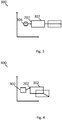
- Figure 5 shows an exemplary scenario 500 of an object-controlled movement of a vehicle body part 502, for example a door of the vehicle 302.
- an object 402 approaches and/or touches the vehicle body part 502 of the vehicle 302.
- the method 100 may receive 102 a first signal of a temperature sensor 206 of the at least one multi-modal tactile sensor 204 of the vehicle body part 502. Additionally or alternatively, the method 100 may receive 102 a first signal of the proximity sensor 212 of the at least one multi-modal tactile sensor 204. Additionally or alternatively, the method 100 may receive 102 a first signal of an accelerator sensor 214 of the at least one multi-modal tactile sensor 204.
- the method 100 may determine 104 the object 402 approaching and/or touching the vehicle body part 306 as the first tactile interaction based on the received first signal. For example, if the first signal indicates a temperature of an object, e.g. a temperature different from a temperature of a person, the method 100 may determine that an object is approaching and/or touching the vehicle body part 502 as the first tactile interaction.
- the first signal indicates a temperature of an object, e.g. a temperature different from a temperature of a person
- the method 100 may determine that an object is approaching and/or touching the vehicle body part 502 as the first tactile interaction.
- the method 100 may receive a micro vibration as the second signal. Additionally or alternatively, the method 100 may receive 102 a distance of the object 402 as the second signal. The method 100 may determine 108 the object 402 approaching and/or touching the vehicle body part 502 as the second tactile interaction based on the received micro vibration and/or the received distance of the object 402. The method 100 may determine a movement pattern 308 of the vehicle body part 502 to avoid a collision of the object with the vehicle body part 502 and may control the movement of the vehicle body part 502 of the vehicle 302 using the movement pattern. Accordingly, an object may move the vehicle body part 502 using the at least one multi-modal tactile sensor 204.
- a person may efficiently move a vehicle, e.g. a car, into a parking space by pushing and/or touching the vehicle using at least one multi-modal tactile sensor.
- a person may also use the at least one multi-model tactile sensor to move vehicle in order to increase a parking space so that the vehicle may use the parking space.
- a person may efficiently move a vehicle out of a parking space.
- the multi-modal tactile sensor may efficiently enable additional functionality by adding further tactile interaction pattern which are associated to different vehicle functions. For example, the vehicle may be turned-off or turned-on by tapping on a particular vehicle body part of the exterior of the vehicle, and/or the vehicle may detect a collision or a hit of another parking vehicle.
Abstract
Description
- The present invention relates to a method for controlling a movement of a vehicle. In particular, a multi-modal tactile sensor may be used to control the movement of the vehicle.
- Current vehicles may use multiple sensors to detect objects in the environment of the vehicle. For example, current vehicles may use camera, LIDAR, radar, and further sensors to detect objects in the environment. Further, current vehicles may comprise a touch sensor or a proximity sensor in the exterior of the vehicle which may be used to unlock a door of the vehicle. However, current vehicle cannot detect a tactile interaction with the exterior the vehicle which allows controlling a movement of the vehicle.
- Accordingly, there may be a need for efficiently controlling a movement of a vehicle. In particular, there may be a need for efficiently controlling a movement of a vehicle from the exterior of the vehicle.
- This need may be met by the subject matter according to the independent claims. Advantageous embodiments of the present invention are described by the dependent claims.
- According to a first aspect of the invention, there is provided a method for controlling a movement of a vehicle. The vehicle may be a self-driving vehicle. The vehicle may be a partially autonomous driving, a highly autonomous driving, or a fully autonomous driving vehicle. The vehicle comprises a vehicle body part of an exterior of the vehicle. The vehicle body part of the exterior of the vehicle comprises at least one multi-modal tactile sensor. Preferably, the at least one multi-model tactile sensor is integrated in or attached to the vehicle body part of the exterior of the vehicle. The vehicle body part may comprise an array of multi-modal tactile sensors. The at least one multi-modal tactile sensor may be accessible from the outer surface of the vehicle body part. The method receives a first signal of the at least one multi-modal tactile sensor of the vehicle body part. For example an electronic control unit of the vehicle may receive the first signal. The method determines a first tactile interaction with the vehicle body part based on the first signal of the at least one multi-modal tactile sensor. Further, the method receives a second signal of the at least one multi-modal tactile sensor of the vehicle body part, the second signal depending on the first tactile interaction, and determines a second tactile interaction with the vehicle body part based on the second signal of the at least one multi-modal tactile sensor. Based on the second tactile interaction, the method determines a movement pattern of the vehicle. Finally, the method controls the movement of the vehicle using the movement pattern.
- This may provide the advantage that the movement of the vehicle may be efficiently controlled by at least one tactile sensor located at the exterior of the vehicle. Only a first tactile interaction and/or a second tactile interaction is necessary to control the movement of the vehicle. Accordingly, the movement of the vehicle is simplified using the at least one multi-modal tactile sensor. For example, the position of the vehicle may be efficiently adapted from outside of the vehicle by tactile interaction with the vehicle.
- According to an embodiment of the invention, the vehicle may be a parked vehicle, and/or the vehicle may be a stationary vehicle. This may provide the advantage that a parking vehicle may be efficiently moved by the first and second touch interaction. Accordingly, the vehicle may be repositioned in a parking space by tactile interaction with the vehicle in order to make further parking space available.
- According to a further embodiment of the invention, the vehicle body part of the exterior of the vehicle may comprise an array of multi-modal tactile sensors. This may provide the advantage that a larger space of the exterior of the vehicle may be used for tactile interaction with the vehicle.
- According to a further embodiment of the invention, each multi-modal tactile sensor may comprise at least one pressure sensor, at least one a shear force sensor, at least one proximity sensor, at least one accelerometer sensor, and/or at least one temperature sensor. This may provide the advantage that each multi-modal tactile sensor is able to measure a plurality of different and/or complex tactile interactions. Accordingly, a multi-modal tactile sensor may be used more flexible.
- According to a further embodiment of the invention, the first signal may comprise a signal of the at least one temperature sensor of the at least one multi-model tactile sensor, and preferably comprises a signal of the at least one proximity sensor of the at least one multi-model tactile sensor. This may provide the advantage that a person and/or an object may be efficiently detected based on the temperature.
- According to a further embodiment of the invention, the first tactile interaction may comprise a human interaction or an object-based interaction. This may provide the advantage that different tactile interactions may be detected more efficiently.
- According to a further embodiment of the invention, the second signal may comprise a signal of at least one pressure sensor, at least one a shear force sensor, at least one proximity sensor, and/or at least one accelerometer sensor of the at least one multi-model tactile sensor. This may provide the advantage that multiple tactile interactions may be efficiently measured by the at least one multi-modal tactile sensor.
- According to a further embodiment of the invention, the second tactile interaction may comprise a push interaction or a touch interaction if the first tactile interaction indicates a human interaction. This may provide the advantage that more complex tactile interactions may be determined efficiently.
- According to a further embodiment of the invention, the second tactile interaction may comprise an object-vehicle-distance interaction if the first tactile interaction indicates an object-based interaction. This may provide the advantage that a collision of the object with the vehicle may be efficiently avoided.
- According to a further embodiment of the invention, the movement pattern may depend on a force distribution of the at least one pressure sensor, and/or the at least one a shear force sensor of the at least one multi-model tactile sensor. This may provide the advantage that the vehicle may be moved efficiently by one or more tactile interactions.
- According to a further aspect of the invention, there is provided a system for controlling a movement of a vehicle, wherein the vehicle comprises a vehicle body part of an exterior of the vehicle, and wherein the vehicle body part of the exterior of the vehicle comprises at least one multi-modal tactile sensor, the system comprising a processor, a memory, and instructions stored within the memory, wherein the instructions, when executed on the processor, cause the system to receive a first signal of the at least one multi-modal tactile sensor of the vehicle body part, to determine a first tactile interaction with the vehicle body part based on the first signal of the at least one multi-modal tactile sensor, to receive a second signal of the at least one multi-modal tactile sensor of the vehicle body part, the second signal depending on the first tactile interaction, to determine a second tactile interaction with the vehicle body part based on the second signal of the at least one multi-modal tactile sensor, to determine a movement pattern of the vehicle based on the second tactile interaction, and to control the movement of the vehicle using the movement pattern.
- According to an embodiment of the invention, the system may further comprise instructions stored within the memory, wherein the instructions, when executed on the processor, cause the system to carry out the method as described above.
- According to a further aspect of the invention, there is provided a computer program product for controlling the movement of a vehicle, the computer program product, when being executed by a processor, is adapted for controlling and/or for carrying out the method as described above.
- As used herein, reference to a computer program or a computer program product is intended to be equivalent to a reference to a program element and/or to a computer readable medium containing instructions for controlling a computer system to coordinate the performance of the above described method.
- The computer program may be implemented as computer readable instruction code in any suitable programming language and may be stored on a computer-readable medium (removable disk, volatile or non-volatile memory, embedded memory/processor, etc.). The instruction code is operable to program a computer or any other programmable device to carry out the intended functions. The computer program may be available from a network, such as the World Wide Web, from which it may be downloaded.
- The invention may be realized by means of a computer program respectively software. However, the invention may also be realized by means of one or more specific electronic circuits respectively hardware. Furthermore, the invention may also be realized in a hybrid form, i.e. in a combination of software modules and hardware modules.
- It has to be noted that embodiments of the invention have been described with reference to different subject matters. In particular, some embodiments have been described with reference to method type claims whereas other embodiments have been described with reference to apparatus type claims. However, a person skilled in the art will gather from the above and the following description that, unless other notified, in addition to any combination of features belonging to one type of subject matter also any combination between features relating to different subject matters, in particular between features of the method type claims and features of the apparatus type claims is considered as to be disclosed with this document.
- The aspects defined above and further aspects of the present invention are apparent from the examples of embodiment to be described hereinafter and are explained with reference to the examples of embodiment. The invention will be described in more detail hereinafter with reference to examples of embodiment but to which the invention is not limited.
-
-
Figure 1 shows an exemplary method for controlling a movement of a vehicle, -
Figure 2 shows an exemplary array of multi-modal tactile sensors, -
Figure 3 shows an exemplary scenario of a human-controlled movement of a vehicle, -
Figure 4 shows an exemplary scenario of an object-controlled movement of a vehicle, and -
Figure 5 shows an exemplary scenario of an object-controlled movement of a vehicle body part. - The illustration in the drawing is schematically. It is noted that in different figures, similar or identical elements are provided with the same reference signs or with reference signs, which are different from the corresponding reference signs only within the first digit.
-
Figure 1 shows anexemplary method 100 for controlling a movement of a vehicle. Additionally or alternatively, themethod 100 may control a movement of a vehicle body part, e.g. a door of the vehicle. Further, the method may control a movement of the vehicle and a vehicle body part, e.g. the vehicle and the vehicle body part may be controlled in a manner that the vehicle and the vehicle body part may move independently from each other at the same time. - The vehicle may comprise at least one vehicle body part of an exterior of the vehicle. The at least one vehicle body part of the exterior of the vehicle may comprise at least one multi-modal tactile sensor. Preferably, multiple vehicle body parts of the exterior of the vehicle may comprise at least one multi-modal tactile sensor. Preferably, each vehicle body part comprises an array of multi-modal tactile sensors. The number of multi-modal tactile sensors may depend from the size of the vehicle body part and/or the size of an area of the vehicle body part which may receive tactile input.
- In particular,
Figure 2 showsexemplary array 200 of multi-modaltactile sensors 204 of avehicle body part 202. As depicted inFigure 2 , each multi-modaltactile sensor 204 may comprise at least onetemperature sensor 206, at least onepressure sensor 208, at least one ashear force sensor 210, at least oneproximity sensor 212, and at least oneaccelerometer sensor 214. Atemperature sensor 206 of the multi-modaltactile sensor 204 may measure a temperature of an object and/or a person touching thevehicle body part 202. Apressure sensor 208 of the multi-modaltactile sensor 204 may measure a normal force. Ashear force sensor 210 of the multi-modaltactile sensor 204 may measure a tangential force. Aproximity sensor 212 of the multi-modaltactile sensor 204 may measure a pre-touch distance and/or a pre-contact distance between an object or a person and thevehicle body part 202. Anaccelerator sensor 214 of the multi-modaltactile sensor 204 may measure a micro vibration and/or a vibration-tactile contact of an object and/or a person. - The
method 100 may receive 102 a first signal of the at least one multi-modaltactile sensor 204 of thevehicle body part 202. In particular, themethod 100 may receive the first signal of a sensor included in the at least one multi-modaltactile sensor 204. Preferably, the method may receive the first signal from a temperature sensor of the at least one multi-modaltactile sensor 204. Themethod 100 may determine 104 a first tactile interaction with thevehicle body 202 part based on the first signal of the at least one multi-modeltactile sensor 204. For example, the first tactile interaction may comprise a person touching thevehicle body part 202 or an object approaching and/or touching thevehicle body part 202. - The
method 100 may further receive 106 a second signal of the at least one multi-modaltactile sensor 204 of thevehicle body part 202. The second signal may be a signal of a further sensor of the at least one multi-modaltactile sensor 204. The second signal may depend on the first tactile interaction. Next, themethod 100 may determine 108 a second tactile interaction with thevehicle body part 202 based on the second signal of the at least one multi-modaltactile sensor 204. Based on the second tactile interaction, themethod 100 may determine 110 a movement pattern of the vehicle and/or at least thevehicle body part 202. Finally, themethod 100 may control 112 the movement of the vehicle and/or at least the movement of thevehicle body part 202 using the movement pattern. -
Figure 3 shows anexemplary scenario 300 of a human-controlled movement of avehicle 302. As illustrated inFigure 3 , a person 304 touches avehicle body part 202 of thevehicle 302. Themethod 100 may receive 102 a first signal of atemperature sensor 206 of the at least one multi-modaltactile sensor 204 of thevehicle body part 202. Themethod 100 may determine 104 a person 304 touching thevehicle body part 202 as the first tactile interaction based on the received first signal. For example, if the first signal indicates a temperature of a person 304, themethod 100 may determine that a person 304 is touching thevehicle body part 202 as the first tactile interaction. - Further, the
method 100 may receive a force distribution as the second signal. The force distribution may be generated using thepressure sensor 208 of the at least one multi-modaltactile sensor 204 and theshear force sensor 210 of the at least one multi-modaltactile sensor 204. Themethod 100 may determine 108 a person pushing the vehicle body part 306 as the second tactile interaction based on the received force distribution. Based on the force distribution, themethod 100 may determine a movement pattern of thevehicle 302 and may control the movement of thevehicle 302 using the movement pattern. Accordingly, a person 304 may move thevehicle 302 using the at least one multi-modaltactile sensor 204. -
Figure 4 shows anexemplary scenario 400 of an object-controlled movement of thevehicle 302. As illustrated inFigure 4 , anobject 402 approaches and/or touches the vehicle body part 306 of thevehicle 302. Themethod 100 may receive 102 a first signal of atemperature sensor 206 of the at least one multi-modaltactile sensor 204 of the vehicle body part 306. Additionally or alternatively, themethod 100 may receive 102 a first signal of theproximity sensor 212 of the at least one multi-modaltactile sensor 204. Additionally or alternatively, themethod 100 may receive 102 a first signal of anaccelerator sensor 214 of the at least one multi-modaltactile sensor 204. Themethod 100 may determine 104 theobject 402 approaching and/or touching thevehicle body part 202 as the first tactile interaction based on the received first signal. For example, if the first signal indicates a temperature of an object, e.g. a temperature different from the temperature of a person, themethod 100 may determine that theobject 402 is approaching or touching thevehicle body part 202 as the first tactile interaction. - Further, the
method 100 may receive a micro vibration as the second signal. Additionally or alternatively, themethod 100 may receive 102 a distance of theobject 402 as the second signal. Themethod 100 may determine 108 theobject 402 approaching and/or touching the vehicle body part 306 as the second tactile interaction based on the received micro vibration and/or the received distance of the object. Themethod 100 may determine a movement pattern 308 of thevehicle 302 to avoid a collision of theobject 402 and may control the movement of thevehicle 302 using the movement pattern. Accordingly, theobject 402 may move thevehicle 302 to avoid a collision using the at least one multi-modaltactile sensor 204. -
Figure 5 shows anexemplary scenario 500 of an object-controlled movement of avehicle body part 502, for example a door of thevehicle 302. As illustrated inFigure 5 , anobject 402 approaches and/or touches thevehicle body part 502 of thevehicle 302. Themethod 100 may receive 102 a first signal of atemperature sensor 206 of the at least one multi-modaltactile sensor 204 of thevehicle body part 502. Additionally or alternatively, themethod 100 may receive 102 a first signal of theproximity sensor 212 of the at least one multi-modaltactile sensor 204. Additionally or alternatively, themethod 100 may receive 102 a first signal of anaccelerator sensor 214 of the at least one multi-modaltactile sensor 204. Themethod 100 may determine 104 theobject 402 approaching and/or touching the vehicle body part 306 as the first tactile interaction based on the received first signal. For example, if the first signal indicates a temperature of an object, e.g. a temperature different from a temperature of a person, themethod 100 may determine that an object is approaching and/or touching thevehicle body part 502 as the first tactile interaction. - Further, the
method 100 may receive a micro vibration as the second signal. Additionally or alternatively, themethod 100 may receive 102 a distance of theobject 402 as the second signal. Themethod 100 may determine 108 theobject 402 approaching and/or touching thevehicle body part 502 as the second tactile interaction based on the received micro vibration and/or the received distance of theobject 402. Themethod 100 may determine a movement pattern 308 of thevehicle body part 502 to avoid a collision of the object with thevehicle body part 502 and may control the movement of thevehicle body part 502 of thevehicle 302 using the movement pattern. Accordingly, an object may move thevehicle body part 502 using the at least one multi-modaltactile sensor 204. - Advantageously, a person may efficiently move a vehicle, e.g. a car, into a parking space by pushing and/or touching the vehicle using at least one multi-modal tactile sensor. A person may also use the at least one multi-model tactile sensor to move vehicle in order to increase a parking space so that the vehicle may use the parking space. Additionally or alternatively, a person may efficiently move a vehicle out of a parking space. The multi-modal tactile sensor may efficiently enable additional functionality by adding further tactile interaction pattern which are associated to different vehicle functions. For example, the vehicle may be turned-off or turned-on by tapping on a particular vehicle body part of the exterior of the vehicle, and/or the vehicle may detect a collision or a hit of another parking vehicle.
- It should be noted that the term "comprising" does not exclude other elements or steps and the use of articles "a" or "an" does not exclude a plurality. Also elements described in association with different embodiments may be combined. It should also be noted that reference signs in the claims should not be construed as limiting the scope of the claims.
-
- 100
- method
- 102
- receive first signal
- 104
- determine first tactile interaction
- 106
- receive second signal
- 108
- determine second tactile interaction
- 110
- determine movement pattern
- 112
- control movement
- 200
- array of multi-modal tactile sensors
- 202
- vehicle body part
- 204
- multi-modal tactile sensor
- 206
- temperature sensor
- 208
- pressure sensor
- 210
- shear force sensor
- 212
- proximity sensor
- 214
- accelerometer sensor
- 300
- scenario
- 302
- vehicle
- 304
- person
- 400
- scenario
- 402
- object
- 500
- scenario
- 502
- vehicle body part
Claims (13)
- Method for controlling a movement of a vehicle, wherein the vehicle comprises a vehicle body part of an exterior of the vehicle, and wherein the vehicle body part of the exterior of the vehicle comprises at least one multi-modal tactile sensor, the method comprising:- receiving a first signal of the at least one multi-modal tactile sensor of the vehicle body part;- determining a first tactile interaction with the vehicle body part based on the first signal of the at least one multi-modal tactile sensor;- receiving a second signal of the at least one multi-modal tactile sensor of the vehicle body part, the second signal depending on the first tactile interaction;- determining a second tactile interaction with the vehicle body part based on the second signal of the at least one multi-modal tactile sensor;- determining a movement pattern of the vehicle based on the second tactile interaction; and- controlling the movement of the vehicle using the movement pattern.
- Method according to claim 1, wherein the vehicle is a parked vehicle; and/or wherein the vehicle is a stationary vehicle.
- Method according to any one of claims 1 to 2, wherein the vehicle body part of the exterior of the vehicle comprises an array of multi-modal tactile sensors.
- Method according to any one of claims 1 to 3, wherein each multi-modal tactile sensor comprises at least one pressure sensor, at least one a shear force sensor, at least one proximity sensor, at least one accelerometer sensor, and/or at least one temperature sensor.
- Method according to any one of claims 1 to 4, wherein the first signal comprises a signal of the at least one temperature sensor of the at least one multi-model tactile sensor and, preferably, a signal of the at least one proximity sensor of the at least one multi-model tactile sensor.
- Method according to any one of claims 1 to 5, wherein the first tactile interaction comprises a human interaction or an object-based interaction.
- Method according to any one of claims 1 to 6, wherein the second signal comprises a signal of at least one pressure sensor, at least one a shear force sensor, at least one proximity sensor, and/or at least one accelerometer sensor of the at least one multi-model tactile sensor.
- Method according to any one of claims 1 to 7, wherein the second tactile interaction comprises a push interaction or a touch interaction if the first tactile interaction indicates a human interaction.
- Method according to any one of claims 1 to 8, wherein the second tactile interaction comprises an object-vehicle-distance interaction if the first tactile interaction indicates an object-based interaction.
- Method according to any one of claims 1 to 9, wherein the movement pattern depends on a force distribution of the at least one pressure sensor, and/or the at least one a shear force sensor of the at least one multi-model tactile sensor.
- System for controlling a movement of a vehicle, wherein the vehicle comprises a vehicle body part of an exterior of the vehicle, and wherein the vehicle body part of the exterior of the vehicle comprises at least one multi-modal tactile sensor, the system comprising:a processor,a memory, andinstructions stored within the memory, wherein the instructions, when executed on the processor, cause the system to- receive a first signal of the at least one multi-modal tactile sensor of the vehicle body part;- determine a first tactile interaction with the vehicle body part based on the first signal of the at least one multi-modal tactile sensor;- receive a second signal of the at least one multi-modal tactile sensor of the vehicle body part, the second signal depending on the first tactile interaction;- determine a second tactile interaction with the vehicle body part based on the second signal of the at least one multi-modal tactile sensor;- determine a movement pattern of the vehicle based on the second tactile interaction; and- control the movement of the vehicle using the movement pattern.
- System according to claim 11, the system further comprising instructions stored within the memory, wherein the instructions, when executed on the processor, cause the system to carry out the method according to any one of claims 2 to 10.
- Computer program product for controlling the movement of a vehicle, the computer program product, when being executed by a processor, is adapted for controlling and/or for carrying out the method as set forth in any one of the claims 1 to 10.
Priority Applications (1)
| Application Number | Priority Date | Filing Date | Title |
|---|---|---|---|
| EP19159913.3A EP3702865B1 (en) | 2019-02-28 | 2019-02-28 | Method, system, and computer program product for controlling a movement of a vehicle |
Applications Claiming Priority (1)
| Application Number | Priority Date | Filing Date | Title |
|---|---|---|---|
| EP19159913.3A EP3702865B1 (en) | 2019-02-28 | 2019-02-28 | Method, system, and computer program product for controlling a movement of a vehicle |
Publications (2)
| Publication Number | Publication Date |
|---|---|
| EP3702865A1 true EP3702865A1 (en) | 2020-09-02 |
| EP3702865B1 EP3702865B1 (en) | 2022-09-07 |
Family
ID=65801818
Family Applications (1)
| Application Number | Title | Priority Date | Filing Date |
|---|---|---|---|
| EP19159913.3A Active EP3702865B1 (en) | 2019-02-28 | 2019-02-28 | Method, system, and computer program product for controlling a movement of a vehicle |
Country Status (1)
| Country | Link |
|---|---|
| EP (1) | EP3702865B1 (en) |
Cited By (1)
| Publication number | Priority date | Publication date | Assignee | Title |
|---|---|---|---|---|
| FR3106328A1 (en) * | 2020-01-17 | 2021-07-23 | Psa Automobiles Sa | Method and system for managing a maneuver of a motor vehicle facing a parking space by applied force |
Citations (3)
| Publication number | Priority date | Publication date | Assignee | Title |
|---|---|---|---|---|
| GB2536709A (en) * | 2015-03-27 | 2016-09-28 | Jaguar Land Rover Ltd | External vehicle control system |
| US20170192428A1 (en) * | 2016-01-04 | 2017-07-06 | Cruise Automation, Inc. | System and method for externally interfacing with an autonomous vehicle |
| US20170189249A1 (en) * | 2016-01-05 | 2017-07-06 | Eti Ca Battery Inc. | Wheelchair control system and control method using the same |
-
2019
- 2019-02-28 EP EP19159913.3A patent/EP3702865B1/en active Active
Patent Citations (3)
| Publication number | Priority date | Publication date | Assignee | Title |
|---|---|---|---|---|
| GB2536709A (en) * | 2015-03-27 | 2016-09-28 | Jaguar Land Rover Ltd | External vehicle control system |
| US20170192428A1 (en) * | 2016-01-04 | 2017-07-06 | Cruise Automation, Inc. | System and method for externally interfacing with an autonomous vehicle |
| US20170189249A1 (en) * | 2016-01-05 | 2017-07-06 | Eti Ca Battery Inc. | Wheelchair control system and control method using the same |
Non-Patent Citations (1)
| Title |
|---|
| TRUJILLO-LEON A ET AL: "Evaluation of tactile sensors as an alternative to force sensors in an assistive haptic handlebar", 2017 IEEE BIOMEDICAL CIRCUITS AND SYSTEMS CONFERENCE (BIOCAS), IEEE, 19 October 2017 (2017-10-19), pages 1 - 4, XP033340851, DOI: 10.1109/BIOCAS.2017.8325118 * |
Cited By (1)
| Publication number | Priority date | Publication date | Assignee | Title |
|---|---|---|---|---|
| FR3106328A1 (en) * | 2020-01-17 | 2021-07-23 | Psa Automobiles Sa | Method and system for managing a maneuver of a motor vehicle facing a parking space by applied force |
Also Published As
| Publication number | Publication date |
|---|---|
| EP3702865B1 (en) | 2022-09-07 |
Similar Documents
| Publication | Publication Date | Title |
|---|---|---|
| US9440537B2 (en) | Method and device for operating functions displayed on a display unit of a vehicle using gestures which are carried out in a three-dimensional space, and corresponding computer program product | |
| US9994233B2 (en) | Hands accelerating control system | |
| US9358887B2 (en) | User interface | |
| CN107839689B (en) | Autonomous sensing vehicle pedal | |
| CN105916751B (en) | Vehicle is run according to the expectation of vehicle occupant | |
| WO2016073067A1 (en) | Elevator passenger tracking control and call cancellation system | |
| CN108170264B (en) | Vehicle user input control system and method | |
| WO2016085368A1 (en) | Method and system for gesture based control of device | |
| US9949107B2 (en) | Method and system for detecting an input to a device | |
| EP2998840A1 (en) | Capacitive touch sensor device and controller | |
| EP3702865A1 (en) | Method, system, and computer program product for controlling a movement of a vehicle | |
| CN104395859A (en) | Operating system for motor vehicle | |
| CN115003462A (en) | Force limitation during robot manipulator collision | |
| US20170024022A1 (en) | Human machine interface system for controlling vehicular graphical user interface display | |
| US11518242B2 (en) | Systems and methods for locking an input area associated with detected touch location in a force-based touch display | |
| KR20170086103A (en) | Graphical interface and method for managing said graphical interface during the touch-selection of a displayed element | |
| EP3352058A1 (en) | Operation detection device | |
| US9823780B2 (en) | Touch operation detection apparatus | |
| CN110371118A (en) | Device and method for controlling the lane changing of vehicle | |
| CN108255400A (en) | Car-mounted terminal operating method and car-mounted terminal | |
| US11126265B2 (en) | Wearable haptic feedback | |
| JP7363574B2 (en) | object detection device | |
| JP6177627B2 (en) | Touch operation device and touch operation program | |
| WO2012012099A2 (en) | System and method for distinguishing input objects | |
| EP2778844A1 (en) | Gesture recognition system operability verification |
Legal Events
| Date | Code | Title | Description |
|---|---|---|---|
| PUAI | Public reference made under article 153(3) epc to a published international application that has entered the european phase |
Free format text: ORIGINAL CODE: 0009012 |
|
| STAA | Information on the status of an ep patent application or granted ep patent |
Free format text: STATUS: THE APPLICATION HAS BEEN PUBLISHED |
|
| AK | Designated contracting states |
Kind code of ref document: A1 Designated state(s): AL AT BE BG CH CY CZ DE DK EE ES FI FR GB GR HR HU IE IS IT LI LT LU LV MC MK MT NL NO PL PT RO RS SE SI SK SM TR |
|
| AX | Request for extension of the european patent |
Extension state: BA ME |
|
| STAA | Information on the status of an ep patent application or granted ep patent |
Free format text: STATUS: REQUEST FOR EXAMINATION WAS MADE |
|
| 17P | Request for examination filed |
Effective date: 20210128 |
|
| RBV | Designated contracting states (corrected) |
Designated state(s): AL AT BE BG CH CY CZ DE DK EE ES FI FR GB GR HR HU IE IS IT LI LT LU LV MC MK MT NL NO PL PT RO RS SE SI SK SM TR |
|
| STAA | Information on the status of an ep patent application or granted ep patent |
Free format text: STATUS: EXAMINATION IS IN PROGRESS |
|
| 17Q | First examination report despatched |
Effective date: 20210728 |
|
| GRAP | Despatch of communication of intention to grant a patent |
Free format text: ORIGINAL CODE: EPIDOSNIGR1 |
|
| STAA | Information on the status of an ep patent application or granted ep patent |
Free format text: STATUS: GRANT OF PATENT IS INTENDED |
|
| RIC1 | Information provided on ipc code assigned before grant |
Ipc: B62D 51/00 20060101ALN20220519BHEP Ipc: B62D 15/02 20060101ALN20220519BHEP Ipc: B60K 26/00 20060101ALN20220519BHEP Ipc: B60W 50/00 20060101ALN20220519BHEP Ipc: G05D 1/00 20060101AFI20220519BHEP |
|
| INTG | Intention to grant announced |
Effective date: 20220603 |
|
| GRAS | Grant fee paid |
Free format text: ORIGINAL CODE: EPIDOSNIGR3 |
|
| GRAA | (expected) grant |
Free format text: ORIGINAL CODE: 0009210 |
|
| STAA | Information on the status of an ep patent application or granted ep patent |
Free format text: STATUS: THE PATENT HAS BEEN GRANTED |
|
| AK | Designated contracting states |
Kind code of ref document: B1 Designated state(s): AL AT BE BG CH CY CZ DE DK EE ES FI FR GB GR HR HU IE IS IT LI LT LU LV MC MK MT NL NO PL PT RO RS SE SI SK SM TR |
|
| REG | Reference to a national code |
Ref country code: GB Ref legal event code: FG4D |
|
| REG | Reference to a national code |
Ref country code: CH Ref legal event code: EP Ref country code: AT Ref legal event code: REF Ref document number: 1517585 Country of ref document: AT Kind code of ref document: T Effective date: 20220915 |
|
| REG | Reference to a national code |
Ref country code: IE Ref legal event code: FG4D |
|
| REG | Reference to a national code |
Ref country code: DE Ref legal event code: R096 Ref document number: 602019019131 Country of ref document: DE |
|
| REG | Reference to a national code |
Ref country code: LT Ref legal event code: MG9D |
|
| REG | Reference to a national code |
Ref country code: NL Ref legal event code: MP Effective date: 20220907 |
|
| PG25 | Lapsed in a contracting state [announced via postgrant information from national office to epo] |
Ref country code: SE Free format text: LAPSE BECAUSE OF FAILURE TO SUBMIT A TRANSLATION OF THE DESCRIPTION OR TO PAY THE FEE WITHIN THE PRESCRIBED TIME-LIMIT Effective date: 20220907 Ref country code: RS Free format text: LAPSE BECAUSE OF FAILURE TO SUBMIT A TRANSLATION OF THE DESCRIPTION OR TO PAY THE FEE WITHIN THE PRESCRIBED TIME-LIMIT Effective date: 20220907 Ref country code: NO Free format text: LAPSE BECAUSE OF FAILURE TO SUBMIT A TRANSLATION OF THE DESCRIPTION OR TO PAY THE FEE WITHIN THE PRESCRIBED TIME-LIMIT Effective date: 20221207 Ref country code: LV Free format text: LAPSE BECAUSE OF FAILURE TO SUBMIT A TRANSLATION OF THE DESCRIPTION OR TO PAY THE FEE WITHIN THE PRESCRIBED TIME-LIMIT Effective date: 20220907 Ref country code: LT Free format text: LAPSE BECAUSE OF FAILURE TO SUBMIT A TRANSLATION OF THE DESCRIPTION OR TO PAY THE FEE WITHIN THE PRESCRIBED TIME-LIMIT Effective date: 20220907 Ref country code: FI Free format text: LAPSE BECAUSE OF FAILURE TO SUBMIT A TRANSLATION OF THE DESCRIPTION OR TO PAY THE FEE WITHIN THE PRESCRIBED TIME-LIMIT Effective date: 20220907 |
|
| REG | Reference to a national code |
Ref country code: AT Ref legal event code: MK05 Ref document number: 1517585 Country of ref document: AT Kind code of ref document: T Effective date: 20220907 |
|
| PG25 | Lapsed in a contracting state [announced via postgrant information from national office to epo] |
Ref country code: HR Free format text: LAPSE BECAUSE OF FAILURE TO SUBMIT A TRANSLATION OF THE DESCRIPTION OR TO PAY THE FEE WITHIN THE PRESCRIBED TIME-LIMIT Effective date: 20220907 Ref country code: GR Free format text: LAPSE BECAUSE OF FAILURE TO SUBMIT A TRANSLATION OF THE DESCRIPTION OR TO PAY THE FEE WITHIN THE PRESCRIBED TIME-LIMIT Effective date: 20221208 |
|
| PG25 | Lapsed in a contracting state [announced via postgrant information from national office to epo] |
Ref country code: SM Free format text: LAPSE BECAUSE OF FAILURE TO SUBMIT A TRANSLATION OF THE DESCRIPTION OR TO PAY THE FEE WITHIN THE PRESCRIBED TIME-LIMIT Effective date: 20220907 Ref country code: RO Free format text: LAPSE BECAUSE OF FAILURE TO SUBMIT A TRANSLATION OF THE DESCRIPTION OR TO PAY THE FEE WITHIN THE PRESCRIBED TIME-LIMIT Effective date: 20220907 Ref country code: PT Free format text: LAPSE BECAUSE OF FAILURE TO SUBMIT A TRANSLATION OF THE DESCRIPTION OR TO PAY THE FEE WITHIN THE PRESCRIBED TIME-LIMIT Effective date: 20230109 Ref country code: ES Free format text: LAPSE BECAUSE OF FAILURE TO SUBMIT A TRANSLATION OF THE DESCRIPTION OR TO PAY THE FEE WITHIN THE PRESCRIBED TIME-LIMIT Effective date: 20220907 Ref country code: CZ Free format text: LAPSE BECAUSE OF FAILURE TO SUBMIT A TRANSLATION OF THE DESCRIPTION OR TO PAY THE FEE WITHIN THE PRESCRIBED TIME-LIMIT Effective date: 20220907 Ref country code: AT Free format text: LAPSE BECAUSE OF FAILURE TO SUBMIT A TRANSLATION OF THE DESCRIPTION OR TO PAY THE FEE WITHIN THE PRESCRIBED TIME-LIMIT Effective date: 20220907 |
|
| PG25 | Lapsed in a contracting state [announced via postgrant information from national office to epo] |
Ref country code: SK Free format text: LAPSE BECAUSE OF FAILURE TO SUBMIT A TRANSLATION OF THE DESCRIPTION OR TO PAY THE FEE WITHIN THE PRESCRIBED TIME-LIMIT Effective date: 20220907 Ref country code: PL Free format text: LAPSE BECAUSE OF FAILURE TO SUBMIT A TRANSLATION OF THE DESCRIPTION OR TO PAY THE FEE WITHIN THE PRESCRIBED TIME-LIMIT Effective date: 20220907 Ref country code: IS Free format text: LAPSE BECAUSE OF FAILURE TO SUBMIT A TRANSLATION OF THE DESCRIPTION OR TO PAY THE FEE WITHIN THE PRESCRIBED TIME-LIMIT Effective date: 20230107 Ref country code: EE Free format text: LAPSE BECAUSE OF FAILURE TO SUBMIT A TRANSLATION OF THE DESCRIPTION OR TO PAY THE FEE WITHIN THE PRESCRIBED TIME-LIMIT Effective date: 20220907 |
|
| PGFP | Annual fee paid to national office [announced via postgrant information from national office to epo] |
Ref country code: DE Payment date: 20230214 Year of fee payment: 5 |
|
| REG | Reference to a national code |
Ref country code: DE Ref legal event code: R097 Ref document number: 602019019131 Country of ref document: DE |
|
| P01 | Opt-out of the competence of the unified patent court (upc) registered |
Effective date: 20230502 |
|
| PG25 | Lapsed in a contracting state [announced via postgrant information from national office to epo] |
Ref country code: NL Free format text: LAPSE BECAUSE OF FAILURE TO SUBMIT A TRANSLATION OF THE DESCRIPTION OR TO PAY THE FEE WITHIN THE PRESCRIBED TIME-LIMIT Effective date: 20220907 Ref country code: AL Free format text: LAPSE BECAUSE OF FAILURE TO SUBMIT A TRANSLATION OF THE DESCRIPTION OR TO PAY THE FEE WITHIN THE PRESCRIBED TIME-LIMIT Effective date: 20220907 |
|
| PLBE | No opposition filed within time limit |
Free format text: ORIGINAL CODE: 0009261 |
|
| STAA | Information on the status of an ep patent application or granted ep patent |
Free format text: STATUS: NO OPPOSITION FILED WITHIN TIME LIMIT |
|
| PG25 | Lapsed in a contracting state [announced via postgrant information from national office to epo] |
Ref country code: DK Free format text: LAPSE BECAUSE OF FAILURE TO SUBMIT A TRANSLATION OF THE DESCRIPTION OR TO PAY THE FEE WITHIN THE PRESCRIBED TIME-LIMIT Effective date: 20220907 |
|
| 26N | No opposition filed |
Effective date: 20230608 |
|
| PG25 | Lapsed in a contracting state [announced via postgrant information from national office to epo] |
Ref country code: SI Free format text: LAPSE BECAUSE OF FAILURE TO SUBMIT A TRANSLATION OF THE DESCRIPTION OR TO PAY THE FEE WITHIN THE PRESCRIBED TIME-LIMIT Effective date: 20220907 |
|
| PG25 | Lapsed in a contracting state [announced via postgrant information from national office to epo] |
Ref country code: MC Free format text: LAPSE BECAUSE OF FAILURE TO SUBMIT A TRANSLATION OF THE DESCRIPTION OR TO PAY THE FEE WITHIN THE PRESCRIBED TIME-LIMIT Effective date: 20220907 |
|
| REG | Reference to a national code |
Ref country code: CH Ref legal event code: PL |
|
| REG | Reference to a national code |
Ref country code: BE Ref legal event code: MM Effective date: 20230228 |
|
| GBPC | Gb: european patent ceased through non-payment of renewal fee |
Effective date: 20230228 |
|
| PG25 | Lapsed in a contracting state [announced via postgrant information from national office to epo] |
Ref country code: LU Free format text: LAPSE BECAUSE OF NON-PAYMENT OF DUE FEES Effective date: 20230228 Ref country code: LI Free format text: LAPSE BECAUSE OF NON-PAYMENT OF DUE FEES Effective date: 20230228 Ref country code: CH Free format text: LAPSE BECAUSE OF NON-PAYMENT OF DUE FEES Effective date: 20230228 |
|
| REG | Reference to a national code |
Ref country code: IE Ref legal event code: MM4A |
|
| PG25 | Lapsed in a contracting state [announced via postgrant information from national office to epo] |
Ref country code: GB Free format text: LAPSE BECAUSE OF NON-PAYMENT OF DUE FEES Effective date: 20230228 |
|
| PG25 | Lapsed in a contracting state [announced via postgrant information from national office to epo] |
Ref country code: IE Free format text: LAPSE BECAUSE OF NON-PAYMENT OF DUE FEES Effective date: 20230228 Ref country code: GB Free format text: LAPSE BECAUSE OF NON-PAYMENT OF DUE FEES Effective date: 20230228 Ref country code: FR Free format text: LAPSE BECAUSE OF NON-PAYMENT OF DUE FEES Effective date: 20230228 |
|
| PG25 | Lapsed in a contracting state [announced via postgrant information from national office to epo] |
Ref country code: BE Free format text: LAPSE BECAUSE OF NON-PAYMENT OF DUE FEES Effective date: 20230228 |