EP3702770B1 - Kalibrierung eines fotoionisationsdetektors - Google Patents
Kalibrierung eines fotoionisationsdetektors Download PDFInfo
- Publication number
- EP3702770B1 EP3702770B1 EP20160284.4A EP20160284A EP3702770B1 EP 3702770 B1 EP3702770 B1 EP 3702770B1 EP 20160284 A EP20160284 A EP 20160284A EP 3702770 B1 EP3702770 B1 EP 3702770B1
- Authority
- EP
- European Patent Office
- Prior art keywords
- gas
- lamp
- mode
- detector
- data
- Prior art date
- Legal status (The legal status is an assumption and is not a legal conclusion. Google has not performed a legal analysis and makes no representation as to the accuracy of the status listed.)
- Active
Links
Images





Classifications
-
- G—PHYSICS
- G01—MEASURING; TESTING
- G01N—INVESTIGATING OR ANALYSING MATERIALS BY DETERMINING THEIR CHEMICAL OR PHYSICAL PROPERTIES
- G01N27/00—Investigating or analysing materials by the use of electric, electrochemical, or magnetic means
- G01N27/62—Investigating or analysing materials by the use of electric, electrochemical, or magnetic means by investigating the ionisation of gases, e.g. aerosols; by investigating electric discharges, e.g. emission of cathode
- G01N27/64—Investigating or analysing materials by the use of electric, electrochemical, or magnetic means by investigating the ionisation of gases, e.g. aerosols; by investigating electric discharges, e.g. emission of cathode using wave or particle radiation to ionise a gas, e.g. in an ionisation chamber
- G01N27/66—Investigating or analysing materials by the use of electric, electrochemical, or magnetic means by investigating the ionisation of gases, e.g. aerosols; by investigating electric discharges, e.g. emission of cathode using wave or particle radiation to ionise a gas, e.g. in an ionisation chamber and measuring current or voltage
-
- G—PHYSICS
- G01—MEASURING; TESTING
- G01N—INVESTIGATING OR ANALYSING MATERIALS BY DETERMINING THEIR CHEMICAL OR PHYSICAL PROPERTIES
- G01N33/00—Investigating or analysing materials by specific methods not covered by groups G01N1/00 - G01N31/00
- G01N33/0004—Gaseous mixtures, e.g. polluted air
- G01N33/0009—General constructional details of gas analysers, e.g. portable test equipment
- G01N33/0027—General constructional details of gas analysers, e.g. portable test equipment concerning the detector
- G01N33/0036—General constructional details of gas analysers, e.g. portable test equipment concerning the detector specially adapted to detect a particular component
- G01N33/0047—Organic compounds
Definitions
- the present patent application relates to a gas detector device, a method for monitoring a target gas and a computer program.
- data may be used interchangeably to refer to data that can be transmitted, received and/or stored according to the embodiments of the present invention. Therefore, no such term should be used to limit the scope of the embodiments of the present invention.
- the scope of the present invention is defined by the appended claims.
- data may be received directly from another device or indirectly received through one or a plurality of intermediate devices (such as one or a plurality of servers, relays, routers, network access points, base stations, hosts and repeaters), which are sometimes referred to as "network” herein.
- data may be transmitted directly to another device or indirectly transmitted through one or a plurality of intermediate devices (such as one or a plurality of servers, relays, routers, network access points, base stations, hosts, and repeaters).
- intermediate devices such as one or a plurality of servers, relays, routers, network access points, base stations, hosts, and repeaters.
- Various embodiments of the present disclosure relate to a system, method, and device configured to provide improved gas detection by using a photoionization detector (PID).
- PID photoionization detector
- Gas detector calibration is improved so as to achieve more consistent and accurate readings.
- the terms "gas detector”, “gas sensor”, or “detector” may be used interchangeably.
- the electrodes When the target gas is ionized, the electrodes may also be ionized by the UV light, resulting in computing concentration of the target gas that is inaccurate. This type of ionization is referred to as photoelectric noise.
- Existing gas detectors in the prior art cannot determine or consider the photoelectric noise generated by the UV lamp ionization of the electrodes. For example, the existing gas detector is calibrated when the UV lamp is turned OFF. A zero level is established when the UV lamp is turned OFF. Once the UV lamp is turned ON, the concentration of the target gas is determined based on the zero level. Therefore, any photoelectric noise generated by the UV lamp that ionizes the electrodes is incorporated into the computed concentration of the target gas, resulting in the concentration of the target gas being artificially high.
- An improved gas detector and a method for detecting a target gas are provided herein.
- an absolute zero level (which may be averaged over time) is determined when the UV lamp is turned OFF.
- the UV lamp being turned OFF is referred to as the "second mode" of the UV lamp.
- the UV lamp can be turned ON.
- the UV lamp being turned ON is referred to as the "first mode”.
- the photoelectric noise of the UV light is determined when the target gas is not ionized at all. This reading can be referred to as "deviation".
- the target gas is prevented from entering the gas detector.
- the target gas may be prevented by including a calibration filter in the gas detector; injecting or pulling the calibration gas through the gas detector to prevent the target gas from moving through the gas detector; preventing the target gas from moving through the gas detector using other manners; or adopting a combination thereof. Any suitable method capable of preventing the target gas from moving through the gas detector and being ionized by the UV lamp may be used.
- the calibration filter or other methods for preventing the target gas from being ionized by the UV lamp may be removed or stopped, so that the target gas or the external environment that may contain the target gas can be allowed to enter the gas detector and be ionized by the UV lamp.
- the operating mode of the gas detector can be referred to as "normal mode".
- the gas detector can determine the concentration of the target gas in the external environment by using the deviation.
- the calibrated output reading is obtained by subtracting the deviation from the detector signal of the gas detector indicating the concentration of the target gas in the external environment.
- the deviation may be an average value obtained by averaging a plurality of detector signals of the gas detector. Then, the average value can be subtracted from the later detector signal to obtain the calibrated output reading.
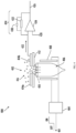
- FIG. 4 illustrates an exemplary gas detector according to the present disclosure.
- the detector signal of the gas detector can be referred to as the theoretical zero or absolute zero level of the concentration of the target gas.
- the fluctuation of the absolute zero level may only be affected by the system noise of the gas detector. If the gas detector can determine the accurate absolute zero level, then the output reading of the target gas can be more reliable and stable. The computed output reading is based on the absolute zero level and the deviation.
- the UV lamp When the UV lamp is turned ON, the UV light can irradiate the target gas and the electrodes in the ion chamber.
- the output signal of the gas detector at this moment comprises the photoelectric noise coming from the ionization of the electrodes and any existing target gas.
- unwanted photoelectric noise may be reduced by adding a UV shielding cover (see, for example, FIG. 4 ).
- a UV shielding cover By incorporating the deviation as disclosed herein into the computation of the concentration of the target gas, other photoelectric noise caused by the ionization of the electrodes can be removed.
- an ultra-low-concentration target gas for example, a target gas with concentration less than 10 ppm, such as at a ppb concentration level
- the photoelectric noise may be particularly harmful to the concentration of the target gas.
- the gas detector and the method for calibrating the gas detector in the present invention provide an integrated solution to reduce the photoelectric noise coming from the output reading of the gas detector (such as a portable PID). Therefore, more accurate target gas readings can be obtained.
- the gas detector and the method for calibrating the gas detector in the present invention can provide more accurate readings than the existing gas detectors that use air calibration sensors.
- the gas detector and the method for calibrating the gas detector in the present invention can allow detecting the ultra-low-concentration target gas (for example, a target gas at a ppb concentration level).
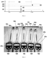
- the gas detector and the method for calibrating the gas detector in the present invention may allow the detecting of target gases at concentration levels less than 10 ppm, such as a ppb concentration level (for example, less than 1 ppm), for example, less than 900 ppb, less than 800 ppb, less than 700 ppb, less than 600 ppb, less than 500 ppb or less than 400 ppb. Even at such low concentration levels, the gas detector and the method for calibrating the gas detector in the present invention can provide improved consistency of output readings improved stability compared with existing gas detectors. Exemplary gas detectors are illustrated in FIG. 5 and FIG. 6 as examples. The present disclosure may be incorporated the following into exemplary gas detectors, such as MinRAE 3000+, MiniRAE Lite+, ppbRAE 3000+, and UtraRAE 3000+.
- the gas detector in the present invention can be in any suitable form, such as in the form of a hand-held device, and can be positioned in a specific environment where the target gas may exist and be detected.
- the gas detector may be installed separately from humans in part of the infrastructure and may be communicatively connected to a monitoring system.
- the gas detector may be carried by a worker in a potentially hazardous working environment.
- the gas detector may be a photoionization detector (PID), an infrared detector, a laser gas detector, and other gas detectors.
- PID photoionization detector
- the deviation may be determined in the IR detector or laser gas detector. Then, when the detector is open to the target gas, the deviation may be used to determine the concentration of the target gas.
- the system, method and device can be used to calibrate the gas detector without obviously interfering with the normal operation of the sensor.
- the gas detector may be calibrated hourly, daily, weekly, monthly, etc.; may be calibrated after a predetermined period of time; may be calibrated as needed; may be calibrated in response to specified events or actions (for example, when a target gas concentration threshold is reached, when the gas detector moves to another position, etc.); or may be calibrated according to a combination thereof.
- the deviation and/or absolute zero level may be determined after a predetermined period of time, as needed, in response to a specified event or action, or according to a combination thereof.
- the calibration of the gas detector may be performed, for example, within less than about 10 minutes, less than about 5 minutes, about 1 minute, or shorter durations. In some embodiments, the deviation may be determined within about 1 minute.
- the electrodes may be added to a substrate (such as a flexible tape, T-I or a combination thereof) by means of screen printing and automatic puddling. Various selective deposition technologies, such as direct puddling, screen printing, or puddling on temporary supports may be used, followed by pressure transfer. Conductors may be used to electrically connect each electrode or several electrodes to a circuit 200.
- the electrodes may be made of the same material or different materials. In some embodiments, the electrodes may be made of one or a plurality of materials, such as platinum, iridium, ruthenium, gold, silver, carbon, or a combination thereof.
- a catalyst material may comprise platinum, iridium, ruthenium, gold, silver, carbon or a mixture thereof, and may be used for the electrodes. The material and structure of the electrodes may be varied based on the expected application of the gas detector.
- the server 140 and/or client device 130 may receive electronic data from various sources (including, but not necessarily limited to, gas detector 400A-400N).
- the server 140 and/or client device 130 may operate to receive or transmit telemetry data provided by the gas detectors 400A-400N, application data, detected gas data, calibration data, gas detector data, and the like.
- the electrode plate 408 operates so as to irradiate UV lamp 406.
- the UV lamp 406 is associated with a UV window 410. UV light emitted from the UV lamp 406 passes through the UV window 410 before irradiating the positions near the first electrode 414a and the second electrode 414b.
- the UV lamp 406 may be a vacuum ultraviolet (VUV) lamp.
- the absolute zero level and the deviation may be determined at the first time, and then the absolute zero level may be updated more frequently than the deviation, or vice versa.
- the absolute zero level may be updated every hour, whereas the deviation is updated at lower frequency or is not updated at all. It can be seen that the deviation is relatively constant, thus frequent updates may not be required.
- the calibration of the gas detector 400 may be performed, for example, within less than about 10 minutes, less than about 5 minutes, about 1 minute, or shorter durations. In some embodiments, the deviation may be determined within about 1 minute.
- FIG. 7a and FIG. 7b illustrate exemplary interfaces 600a, 600b of the gas detector 400 according to one embodiment disclosed herein.
- FIG. 7a and FIG. 7b illustrate operation menus displayed on the exemplary interfaces 600a, 600b of the gas detector 400 according to one embodiment disclosed herein.
- the operation menu is used to calibrate the gas detector 400.
- the operation menu illustrated in FIG. 7b can be displayed.
- zero calibration 701 may be selected to start this method for calibrating the gas detector.
- Actuators 702a, 702b, 702c may be used on interfaces 600a, 600b to initiate desired actions, such as selecting zero calibration 701 of the gas detector 400.
- the gas detector 400 may comprise various input mechanisms, such as buttons, keys and levers, so as to initiate a desired action, which may include calibration of the gas detector 400.
- the calibration of the gas detector 400 may be programmed to be performed periodically or after a certain event occurs (for example, when the calibrated output reading of the target gas is high or the calibrated output reading of the target gas is low).
- the gas detector 400 may be programmed to be calibrated after preset years of use thereof or a predetermined period of use thereof. Without departing from the present disclosure, the gas detector may be programmed to initiate the calibration of the gas detector 400 through various mechanisms and at various points in the use of the gas detector 400.
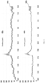
- FIG. 8 illustrates the calibration according to one embodiment disclosed herein.
- the gas detector 400 enables the UV lamp 406 to be in the second mode to determine an absolute zero level 801 by turning OFF the UV lamp 406.
- the absolute zero level 801 may be associated with an average voltage value.
- the absolute zero level 801 represents electric noise 804.
- the UV lamp 406 is turned ON so that it is in the first mode, and the average photoelectric noise 805 of UV light is determined when the target gas is not ionized at all.
- a deviation 802 is illustrated in FIG. 8 .
- the photoelectric noise 805 may change based on the material of the first electrode 414a and the second electrode 414b and/or the intensity of UV light emitted from the UV lamp 406.
- the gas detector 400 saves the deviation 802.
- the gas detector 400 can operate in the normal mode and obtain the true reading of the target gas 416 in the external environment.
- the deviation 802 can be subtracted from the measured output reading 803 to obtain the calibrated output reading 503, which may be the true reading of the concentration of the target gas.
- the deviation 802 can be updated over time (such as within or after a specific period of time).
- the deviation 802 may change when the first electrode 414a and the second electrode 414b are changed or when the light intensity of the UV lamp 406 has changed (for example, if the UV light is contaminated with dust).
- Calibration may be performed at a fixed time such as periodically, or as needed, for example, when required by an operator.
- the calibration may be executed in real time by using automatic zero calibration, so as to ensure that the true reading of the concentration of the target gas is more reliable.
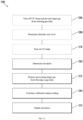
- the step of determining the deviation 1202 may be based on current generated by a pair of electrically biased electrodes of the gas detector when exposed to the UV light emitted from the UV lamp.
- the current may be generated by at least part of the pair of electrically biased electrodes which are ionized when exposed to the UV light emitted from the UV lamp.
- the step of determining the deviation 1202 may comprise averaging a plurality of detector signals based on the current or electrode signals generated by the pair of electrically biased electrodes of the gas detector.
- the step of determining the deviation 1202 may be executed after a predetermined period of time, after a specified event occurs, as needed or according to a combination thereof.
- the method 1200 may further comprise updating the deviation 1214 after a predetermined period of time, after a specified event occurs, as needed or according to a combination thereof.
- the deviation may be updated by preventing the target gas from flowing to the gas inlet and obtaining the detector signals based on the current generated by the pair of electrically biased electrodes of the gas detector.
- the method 1200 further comprises determining an absolute zero level when the UV lamp is in a second mode, wherein the second mode is a non-operating mode of the UV lamp so that photons are not emitted from the UV lamp.
- the computed output reading is based on the deviation and the absolute zero level, so that when the calibrated output reading is computed, the electrical noise seen in the absolute zero level and the photoelectric noise seen in the deviation are considered, and are removed from the calibrated output reading.
Landscapes
- Chemical & Material Sciences (AREA)
- Health & Medical Sciences (AREA)
- Life Sciences & Earth Sciences (AREA)
- Chemical Kinetics & Catalysis (AREA)
- Electrochemistry (AREA)
- Physics & Mathematics (AREA)
- Toxicology (AREA)
- Analytical Chemistry (AREA)
- Biochemistry (AREA)
- General Health & Medical Sciences (AREA)
- General Physics & Mathematics (AREA)
- Immunology (AREA)
- Pathology (AREA)
- Other Investigation Or Analysis Of Materials By Electrical Means (AREA)
- Investigating Or Analysing Materials By Optical Means (AREA)
Claims (8)
- Gasdetektor (400) zum Überwachen eines Zielgases, der Gasdetektor umfassend:einen Gaseingang (403);eine ultraviolette (UV-) Lampe (406);ein Paar von elektrisch vorgespannten Elektroden (414a, 414b), die zwischen dem Gaseingang und der UV-Lampe bereitgestellt sind;einen Schalter (401), der dazu betriebsfähig ist, die UV-Lampe zwischen einem ersten Modus und einem zweiten Modus umzuschalten;und einen Prozessor (210), wobei der Prozessor dazu konfiguriert ist, mit dem Paar von elektrisch vorgespannten Elektroden zu kommunizieren, wobei der Prozessor dazu konfiguriert ist, den Schalter zu betreiben, wobei der Prozessor ferner dazu konfiguriert ist, den Gaseingang zu steuern;und gekennzeichnet dadurch, dass der Prozessor ferner dazu konfiguriert ist, Folgendes durchzuführen:Betreiben der UV-Lampe in einem zweiten Modus, wobei der zweite Modus ein Nichtbetriebsmodus derselben ist, sodass Photonen nicht von der UV-Lampe emittiert werden, und Bestimmen eines absoluten Nullniveaus, wobei das absolute Nullniveau (801) elektrisches Rauschen darstellt;Betreiben der UV-Lampe in einem ersten Modus und Verhindern, dass das Zielgas in den Gaseingang eintritt, wobei der erste Modus der UV-Lampe ein Betriebsmodus der UV-Lampe ist, sodass UV-Licht von ihr emittiert wird, und Bestimmen eines photoelektrischen Rauschniveaus (805) des von der Lampe emittierten UV-Lichts, wenn das Paar von elektrisch vorgespannten Elektroden gegenüber der UV-Lampe in dem ersten Modus exponiert ist und verhindert wird, dass es gegenüber dem Zielgas exponiert ist, wobei das bestimmte photoelektrische Rauschniveau eine Differenz zwischen einem von dem Paar von elektrisch vorgespannten Elektroden erzeugten Elektrodensignal (802) und dem bestimmten absoluten Nullniveau ist;Ausführen einer Echtzeitaktualisierung des absoluten Nullniveaus; undÖffnen des Gaseingangs für das Zielgas, Betreiben der UV-Lampe in dem ersten Modus und Berechnen eines kalibrierten Ausgangsmesswertes (503),wobei der kalibrierte Ausgangsmesswert, wenn das Paar von elektrisch vorgespannten Elektroden gegenüber der UV-Lampe in dem ersten Modus exponiert ist und gegenüber dem Zielgas exponiert ist, das von dem Paar von elektrisch vorgespannten Elektroden erzeugte Elektrodensignal minus dem photoelektrischen Rauschniveau und dem aktualisierten absoluten Nullniveau ist.
- Gasdetektor gemäß Anspruch 1, wobei das Zielgas dadurch daran gehindert wird, in den Gaseingang einzutreten,
dass der Gasdetektor ferner einen Kalibrierungsfilter umfasst, um zu verhindern, dass das Zielgas in den Gaseingang eintritt. - Gasdetektor gemäß Anspruch 1, wobei das photoelektrische Rauschniveau bestimmt wird durch Mitteln einer Vielzahl von Detektorsignalen, und die Vielzahl von Detektorsignalen durch eine Vielzahl von Elektrodensignalen erzeugt wird, die von dem Paar von elektrisch vorgespannten Elektroden erzeugt werden, wenn diese in dem ersten Modus gegenüber der UV-Lampe exponiert sind und verhindert wird, dass sie gegenüber dem Zielgas exponiert sind.
- Gasdetektor gemäß Anspruch 1, wobei der Prozessor dazu konfiguriert ist, das photoelektrische Rauschniveau nach einem vorherbestimmten Zeitraum, nachdem ein spezifiziertes Ereignis eintritt, nach Bedarf oder gemäß einer Kombination daraus zu bestimmen.
- Gasdetektor gemäß Anspruch 1, wobei der Prozessor dazu konfiguriert ist, das photoelektrische Rauschniveau nach einem vorherbestimmten Zeitraum, nachdem ein spezifiziertes Ereignis eintritt, nach Bedarf oder gemäß einer Kombination daraus zu aktualisieren.
- Gasdetektor gemäß Anspruch 1, wobei der kalibrierte Ausgangsmesswert eine Konzentration des Zielgases in einer externen Umgebung in der Einheit Teile pro Milliarde darstellt.
- Verfahren zum Überwachen eines Zielgases unter Verwendung eines Gasdetektors wie in Anspruch 1 definiert, das Verfahren Folgendes umfassend:wenn die UV-Lampe in einem zweiten Modus betrieben wird, wobei der zweite Modus ein Nichtbetriebsmodus derselben ist, sodass Photonen nicht von der UV-Lampe emittiert werden, Bestimmen eines absoluten Nullniveaus, wobei das absolute Nullniveau elektrisches Rauschen darstellt;wenn die UV-Lampe in einem ersten Modus betrieben wird und verhindert wird, dass das Zielgas in den Gaseingang eintritt, wobei der erste Modus der UV-Lampe ein Betriebsmodus der UV-Lampe ist, sodass UV-Licht von derselben emittiert wird, Bestimmen eines photoelektrischen Rauschniveaus des von der Lampe emittierten UV-Lichts, wenn das Paar von elektrisch vorgespannten Elektroden gegenüber der UV-Lampe in dem ersten Modus exponiert ist und verhindert wird, dass es gegenüber dem Zielgas exponiert ist, wobei das bestimmte photoelektrische Rauschniveau eine Differenz zwischen einem von dem Paar von elektrisch vorgespannten Elektroden erzeugten Elektrodensignal und dem bestimmten absoluten Nullniveau ist;Ausführen einer Echtzeitaktualisierung des absoluten Nullniveaus; undwenn der Gaseingang für das Zielgas offen ist, Berechnen eines kalibrierten Ausgangsmesswertes, wobei der kalibrierte Ausgangsmesswerte, wenn das Paar von elektrisch vorgespannten Elektroden gegenüber der UV-Lampe in dem ersten Modus exponiert ist und gegenüber dem Zielgas exponiert ist, das von dem Paar von elektrisch vorgespannten Elektroden erzeugte Elektrodensignal minus dem photoelektrischen Rauschniveau und dem aktualisierten absoluten Nullniveau ist.
- Computerprogramm, umfassend Anweisungen, die bei Ausführung durch den Gasdetektor nach Anspruch 1 den Gasdetektor veranlassen, das Verfahren gemäß Anspruch 7 durchzuführen.
Applications Claiming Priority (1)
| Application Number | Priority Date | Filing Date | Title |
|---|---|---|---|
| CN201920254732.1U CN210376230U (zh) | 2019-02-28 | 2019-02-28 | 用于监测目标气体的气体检测器 |
Publications (2)
| Publication Number | Publication Date |
|---|---|
| EP3702770A1 EP3702770A1 (de) | 2020-09-02 |
| EP3702770B1 true EP3702770B1 (de) | 2025-07-02 |
Family
ID=69743070
Family Applications (1)
| Application Number | Title | Priority Date | Filing Date |
|---|---|---|---|
| EP20160284.4A Active EP3702770B1 (de) | 2019-02-28 | 2020-02-28 | Kalibrierung eines fotoionisationsdetektors |
Country Status (5)
| Country | Link |
|---|---|
| US (3) | US11162917B2 (de) |
| EP (1) | EP3702770B1 (de) |
| CN (1) | CN210376230U (de) |
| AU (2) | AU2020201513B2 (de) |
| CA (1) | CA3074213C (de) |
Families Citing this family (8)
| Publication number | Priority date | Publication date | Assignee | Title |
|---|---|---|---|---|
| WO2018022072A1 (en) | 2016-07-29 | 2018-02-01 | Honeywell International Inc. | Photoionization detector automated zero level calibration |
| CN210376230U (zh) | 2019-02-28 | 2020-04-21 | 霍尼韦尔国际公司 | 用于监测目标气体的气体检测器 |
| CN112179975B (zh) | 2019-07-01 | 2025-10-21 | 霍尼韦尔国际公司 | 用于限制光致电离检测器中的水的方法和系统 |
| US11768177B1 (en) * | 2020-05-29 | 2023-09-26 | Molex, Llc | Ionization device and method of operating same |
| TW202405424A (zh) | 2022-04-19 | 2024-02-01 | 美商英福康公司 | 使用光電離進行過程污染物檢測的分壓力計元件及相關方法 |
| TWI818740B (zh) * | 2022-09-23 | 2023-10-11 | 沃亞科技股份有限公司 | 偵測儀 |
| EP4368988A1 (de) * | 2022-11-11 | 2024-05-15 | Infineon Technologies AG | Gaserfassungsvorrichtung und verfahren zur erfassung eines zielgases |
| US20250216458A1 (en) * | 2024-01-03 | 2025-07-03 | Honeywell International Inc. | Sealed high current switch with internal gas monitor |
Family Cites Families (24)
| Publication number | Priority date | Publication date | Assignee | Title |
|---|---|---|---|---|
| US2901625A (en) * | 1956-01-05 | 1959-08-25 | Friedman Herbert | Ultra-violet gas analysis |
| AU6146394A (en) | 1993-03-05 | 1994-09-26 | Secretary Of State For Defence In Her Britannic Majesty's Government Of The United Kingdom Of Great Britain And Northern Ireland, The | Gas detection devices |
| US5393979A (en) * | 1993-05-12 | 1995-02-28 | Rae Systems, Inc. | Photo-ionization detector for detecting volatile organic gases |
| US5773833A (en) * | 1996-03-22 | 1998-06-30 | Rae Systems, Inc. | Photo-ionization detector for volatile gas measurement |
| US6225633B1 (en) | 1998-10-22 | 2001-05-01 | Rae Systems, Inc. | Photo-ionization detector for volatile gas measurement and a method for self-cleaning the same |
| US6313638B1 (en) * | 1999-03-17 | 2001-11-06 | Rae Systems, Inc. | Dual-channel photo-ionization detector that eliminates the effect of ultraviolet intensity on concentration measurements |
| US6734435B2 (en) | 2001-05-29 | 2004-05-11 | Rae Systems, Inc. | Photo-ionization detector and method for continuous operation and real-time self-cleaning |
| US6967485B1 (en) * | 2003-06-27 | 2005-11-22 | Rae Systems, Inc. | Automatic drive adjustment of ultraviolet lamps in photo-ionization detectors |
| US8323982B2 (en) * | 2007-01-11 | 2012-12-04 | Valencell, Inc. | Photoelectrocatalytic fluid analyte sensors and methods of fabricating and using same |
| US9128061B2 (en) | 2009-02-18 | 2015-09-08 | Beko Technologies Gmbh | Measuring device and method for detecting the hydrocarbon content in gases |
| US9645112B2 (en) * | 2010-01-19 | 2017-05-09 | R2Cd Holdings Pte Ltd. | Auto-cleaning and auto-zeroing system used with a photo-ionization detector |
| US8961418B2 (en) * | 2010-10-06 | 2015-02-24 | Siemens Medical Solutions Usa, Inc. | Solving for shear wave information in medical ultrasound imaging |
| US8922219B2 (en) | 2010-11-30 | 2014-12-30 | General Electric Company | Photo-ionization detectors and associated methods thereof |
| CN102072945A (zh) | 2010-12-20 | 2011-05-25 | 上海精密科学仪器有限公司 | 一种色谱光离子化检测器 |
| US8362445B2 (en) * | 2011-03-30 | 2013-01-29 | Battelle Memorial Institute | UV-LED ionization source and process for low energy photoemission ionization |
| US9459235B2 (en) * | 2012-10-04 | 2016-10-04 | Honeywell International Inc. | Interference compensated photoionization detector |
| CN103424465B (zh) | 2013-07-26 | 2016-05-18 | 华瑞科学仪器(上海)有限公司 | 智能pid传感器模块 |
| US20170304894A1 (en) * | 2014-11-10 | 2017-10-26 | Velo3D, Inc. | Printing three-dimensional objects using beam array |
| CN205027697U (zh) | 2015-06-04 | 2016-02-10 | 河南汉威电子股份有限公司 | 光离子化检测器 |
| WO2018022072A1 (en) | 2016-07-29 | 2018-02-01 | Honeywell International Inc. | Photoionization detector automated zero level calibration |
| WO2018160807A1 (en) * | 2017-03-02 | 2018-09-07 | Velo3D, Inc. | Three-dimensional printing of three dimensional objects |
| US10274369B2 (en) * | 2017-07-14 | 2019-04-30 | Phoseon Technology, Inc. | Systems and methods for an absorbance detector with optical reference |
| JP2021501231A (ja) * | 2017-10-27 | 2021-01-14 | キシレコ インコーポレイテッド | バイオマスの加工方法 |
| CN210376230U (zh) | 2019-02-28 | 2020-04-21 | 霍尼韦尔国际公司 | 用于监测目标气体的气体检测器 |
-
2019
- 2019-02-28 CN CN201920254732.1U patent/CN210376230U/zh active Active
-
2020
- 2020-02-28 EP EP20160284.4A patent/EP3702770B1/de active Active
- 2020-02-28 AU AU2020201513A patent/AU2020201513B2/en active Active
- 2020-02-28 CA CA3074213A patent/CA3074213C/en active Active
- 2020-02-28 US US16/804,066 patent/US11162917B2/en active Active
-
2021
- 2021-09-23 US US17/483,157 patent/US11604163B2/en active Active
- 2021-11-19 AU AU2021269436A patent/AU2021269436B2/en active Active
-
2023
- 2023-01-31 US US18/161,996 patent/US11965855B2/en active Active
Also Published As
| Publication number | Publication date |
|---|---|
| US11162917B2 (en) | 2021-11-02 |
| AU2021269436B2 (en) | 2023-08-03 |
| US11965855B2 (en) | 2024-04-23 |
| CN210376230U (zh) | 2020-04-21 |
| EP3702770A1 (de) | 2020-09-02 |
| AU2020201513A1 (en) | 2020-09-24 |
| US11604163B2 (en) | 2023-03-14 |
| AU2021269436A1 (en) | 2021-12-16 |
| US20220011266A1 (en) | 2022-01-13 |
| US20200278320A1 (en) | 2020-09-03 |
| AU2020201513B2 (en) | 2021-08-19 |
| US20230251225A1 (en) | 2023-08-10 |
| CA3074213C (en) | 2022-09-13 |
| CA3074213A1 (en) | 2020-08-28 |
Similar Documents
| Publication | Publication Date | Title |
|---|---|---|
| AU2021269436B2 (en) | Device for improving gas detection in photoionization detector | |
| Cross et al. | Use of electrochemical sensors for measurement of air pollution: correcting interference response and validating measurements | |
| US8586383B2 (en) | Device and method for detection of harmful substances | |
| JP7827773B2 (ja) | センサ問合せを介したセンサ動作状態の決定 | |
| EP3835783B1 (de) | Automatische nullpegelkalibrierung eines photoionisationsdetektors | |
| US9772279B2 (en) | Sensor for continuous, real-time monitoring of carbon dioxide for chemical contaminants | |
| CN114730184A (zh) | 用于估算逃逸性排放上的变化的计算机系统及方法 | |
| Landi et al. | Reliability and Performance Evaluation of IoT-Based Gas Leakage Detection Systems for Residential Environments | |
| EP3289349B1 (de) | Verfahren und vorrichtung zum identifizieren einer chemikalie | |
| CN119044416A (zh) | 测控装备自检测灰尘、油雾、腐蚀性气体检测方法及系统 | |
| CN119715937A (zh) | 一种基于无线通信的气体标定及信息监控方法及系统 | |
| CN111044571B (zh) | 用于检测气体向气体传感器进入的限制的设备和方法 | |
| EP4318424B1 (de) | Filterlebensdauervorhersage für einen ansaugrauchdetektor | |
| Stroh et al. | Quantifying calibration drift in low-cost PM 10 and sound sensors across contrasting indoor environments | |
| CN120418635A (zh) | 分析装置、分析方法以及程序 | |
| CN121185879A (zh) | 一种基于多模态传感的大气微颗粒物监测装置及方法 |
Legal Events
| Date | Code | Title | Description |
|---|---|---|---|
| PUAI | Public reference made under article 153(3) epc to a published international application that has entered the european phase |
Free format text: ORIGINAL CODE: 0009012 |
|
| STAA | Information on the status of an ep patent application or granted ep patent |
Free format text: STATUS: REQUEST FOR EXAMINATION WAS MADE |
|
| 17P | Request for examination filed |
Effective date: 20200228 |
|
| AK | Designated contracting states |
Kind code of ref document: A1 Designated state(s): AL AT BE BG CH CY CZ DE DK EE ES FI FR GB GR HR HU IE IS IT LI LT LU LV MC MK MT NL NO PL PT RO RS SE SI SK SM TR |
|
| AX | Request for extension of the european patent |
Extension state: BA ME |
|
| STAA | Information on the status of an ep patent application or granted ep patent |
Free format text: STATUS: EXAMINATION IS IN PROGRESS |
|
| 17Q | First examination report despatched |
Effective date: 20220902 |
|
| GRAP | Despatch of communication of intention to grant a patent |
Free format text: ORIGINAL CODE: EPIDOSNIGR1 |
|
| STAA | Information on the status of an ep patent application or granted ep patent |
Free format text: STATUS: GRANT OF PATENT IS INTENDED |
|
| INTG | Intention to grant announced |
Effective date: 20250211 |
|
| GRAS | Grant fee paid |
Free format text: ORIGINAL CODE: EPIDOSNIGR3 |
|
| GRAA | (expected) grant |
Free format text: ORIGINAL CODE: 0009210 |
|
| STAA | Information on the status of an ep patent application or granted ep patent |
Free format text: STATUS: THE PATENT HAS BEEN GRANTED |
|
| AK | Designated contracting states |
Kind code of ref document: B1 Designated state(s): AL AT BE BG CH CY CZ DE DK EE ES FI FR GB GR HR HU IE IS IT LI LT LU LV MC MK MT NL NO PL PT RO RS SE SI SK SM TR |
|
| REG | Reference to a national code |
Ref country code: GB Ref legal event code: FG4D |
|
| REG | Reference to a national code |
Ref country code: CH Ref legal event code: EP |
|
| REG | Reference to a national code |
Ref country code: DE Ref legal event code: R096 Ref document number: 602020053631 Country of ref document: DE |
|
| REG | Reference to a national code |
Ref country code: IE Ref legal event code: FG4D |
|
| REG | Reference to a national code |
Ref country code: NL Ref legal event code: MP Effective date: 20250702 |
|
| PG25 | Lapsed in a contracting state [announced via postgrant information from national office to epo] |
Ref country code: PT Free format text: LAPSE BECAUSE OF FAILURE TO SUBMIT A TRANSLATION OF THE DESCRIPTION OR TO PAY THE FEE WITHIN THE PRESCRIBED TIME-LIMIT Effective date: 20251103 |
|
| PG25 | Lapsed in a contracting state [announced via postgrant information from national office to epo] |
Ref country code: NL Free format text: LAPSE BECAUSE OF FAILURE TO SUBMIT A TRANSLATION OF THE DESCRIPTION OR TO PAY THE FEE WITHIN THE PRESCRIBED TIME-LIMIT Effective date: 20250702 |
|
| REG | Reference to a national code |
Ref country code: AT Ref legal event code: MK05 Ref document number: 1809747 Country of ref document: AT Kind code of ref document: T Effective date: 20250702 |
|
| PG25 | Lapsed in a contracting state [announced via postgrant information from national office to epo] |
Ref country code: IS Free format text: LAPSE BECAUSE OF FAILURE TO SUBMIT A TRANSLATION OF THE DESCRIPTION OR TO PAY THE FEE WITHIN THE PRESCRIBED TIME-LIMIT Effective date: 20251102 |
|
| PG25 | Lapsed in a contracting state [announced via postgrant information from national office to epo] |
Ref country code: NO Free format text: LAPSE BECAUSE OF FAILURE TO SUBMIT A TRANSLATION OF THE DESCRIPTION OR TO PAY THE FEE WITHIN THE PRESCRIBED TIME-LIMIT Effective date: 20251002 |
|
| REG | Reference to a national code |
Ref country code: LT Ref legal event code: MG9D |
|
| PG25 | Lapsed in a contracting state [announced via postgrant information from national office to epo] |
Ref country code: AT Free format text: LAPSE BECAUSE OF FAILURE TO SUBMIT A TRANSLATION OF THE DESCRIPTION OR TO PAY THE FEE WITHIN THE PRESCRIBED TIME-LIMIT Effective date: 20250702 |
|
| PG25 | Lapsed in a contracting state [announced via postgrant information from national office to epo] |
Ref country code: FI Free format text: LAPSE BECAUSE OF FAILURE TO SUBMIT A TRANSLATION OF THE DESCRIPTION OR TO PAY THE FEE WITHIN THE PRESCRIBED TIME-LIMIT Effective date: 20250702 |
|
| PG25 | Lapsed in a contracting state [announced via postgrant information from national office to epo] |
Ref country code: HR Free format text: LAPSE BECAUSE OF FAILURE TO SUBMIT A TRANSLATION OF THE DESCRIPTION OR TO PAY THE FEE WITHIN THE PRESCRIBED TIME-LIMIT Effective date: 20250702 |
|
| PG25 | Lapsed in a contracting state [announced via postgrant information from national office to epo] |
Ref country code: GR Free format text: LAPSE BECAUSE OF FAILURE TO SUBMIT A TRANSLATION OF THE DESCRIPTION OR TO PAY THE FEE WITHIN THE PRESCRIBED TIME-LIMIT Effective date: 20251003 |
|
| PG25 | Lapsed in a contracting state [announced via postgrant information from national office to epo] |
Ref country code: CZ Free format text: LAPSE BECAUSE OF FAILURE TO SUBMIT A TRANSLATION OF THE DESCRIPTION OR TO PAY THE FEE WITHIN THE PRESCRIBED TIME-LIMIT Effective date: 20250702 Ref country code: SE Free format text: LAPSE BECAUSE OF FAILURE TO SUBMIT A TRANSLATION OF THE DESCRIPTION OR TO PAY THE FEE WITHIN THE PRESCRIBED TIME-LIMIT Effective date: 20250702 |
|
| PG25 | Lapsed in a contracting state [announced via postgrant information from national office to epo] |
Ref country code: LV Free format text: LAPSE BECAUSE OF FAILURE TO SUBMIT A TRANSLATION OF THE DESCRIPTION OR TO PAY THE FEE WITHIN THE PRESCRIBED TIME-LIMIT Effective date: 20250702 |
|
| PG25 | Lapsed in a contracting state [announced via postgrant information from national office to epo] |
Ref country code: PL Free format text: LAPSE BECAUSE OF FAILURE TO SUBMIT A TRANSLATION OF THE DESCRIPTION OR TO PAY THE FEE WITHIN THE PRESCRIBED TIME-LIMIT Effective date: 20250702 Ref country code: BG Free format text: LAPSE BECAUSE OF FAILURE TO SUBMIT A TRANSLATION OF THE DESCRIPTION OR TO PAY THE FEE WITHIN THE PRESCRIBED TIME-LIMIT Effective date: 20250702 |
|
| PG25 | Lapsed in a contracting state [announced via postgrant information from national office to epo] |
Ref country code: RS Free format text: LAPSE BECAUSE OF FAILURE TO SUBMIT A TRANSLATION OF THE DESCRIPTION OR TO PAY THE FEE WITHIN THE PRESCRIBED TIME-LIMIT Effective date: 20251002 |
|
| PG25 | Lapsed in a contracting state [announced via postgrant information from national office to epo] |
Ref country code: ES Free format text: LAPSE BECAUSE OF FAILURE TO SUBMIT A TRANSLATION OF THE DESCRIPTION OR TO PAY THE FEE WITHIN THE PRESCRIBED TIME-LIMIT Effective date: 20250702 |
|
| PG25 | Lapsed in a contracting state [announced via postgrant information from national office to epo] |
Ref country code: SM Free format text: LAPSE BECAUSE OF FAILURE TO SUBMIT A TRANSLATION OF THE DESCRIPTION OR TO PAY THE FEE WITHIN THE PRESCRIBED TIME-LIMIT Effective date: 20250702 |
|
| PGFP | Annual fee paid to national office [announced via postgrant information from national office to epo] |
Ref country code: GB Payment date: 20260223 Year of fee payment: 7 |
|
| PG25 | Lapsed in a contracting state [announced via postgrant information from national office to epo] |
Ref country code: DK Free format text: LAPSE BECAUSE OF FAILURE TO SUBMIT A TRANSLATION OF THE DESCRIPTION OR TO PAY THE FEE WITHIN THE PRESCRIBED TIME-LIMIT Effective date: 20250702 |
|
| PGFP | Annual fee paid to national office [announced via postgrant information from national office to epo] |
Ref country code: DE Payment date: 20260220 Year of fee payment: 7 |
|
| PG25 | Lapsed in a contracting state [announced via postgrant information from national office to epo] |
Ref country code: IT Free format text: LAPSE BECAUSE OF FAILURE TO SUBMIT A TRANSLATION OF THE DESCRIPTION OR TO PAY THE FEE WITHIN THE PRESCRIBED TIME-LIMIT Effective date: 20250702 |
|
| PG25 | Lapsed in a contracting state [announced via postgrant information from national office to epo] |
Ref country code: SK Free format text: LAPSE BECAUSE OF FAILURE TO SUBMIT A TRANSLATION OF THE DESCRIPTION OR TO PAY THE FEE WITHIN THE PRESCRIBED TIME-LIMIT Effective date: 20250702 Ref country code: EE Free format text: LAPSE BECAUSE OF FAILURE TO SUBMIT A TRANSLATION OF THE DESCRIPTION OR TO PAY THE FEE WITHIN THE PRESCRIBED TIME-LIMIT Effective date: 20250702 |
|
| PLBE | No opposition filed within time limit |
Free format text: ORIGINAL CODE: 0009261 |
|
| STAA | Information on the status of an ep patent application or granted ep patent |
Free format text: STATUS: NO OPPOSITION FILED WITHIN TIME LIMIT |