EP3702662A1 - Fire suppressant system - Google Patents
Fire suppressant system Download PDFInfo
- Publication number
- EP3702662A1 EP3702662A1 EP20159312.6A EP20159312A EP3702662A1 EP 3702662 A1 EP3702662 A1 EP 3702662A1 EP 20159312 A EP20159312 A EP 20159312A EP 3702662 A1 EP3702662 A1 EP 3702662A1
- Authority
- EP
- European Patent Office
- Prior art keywords
- suppressant
- capacitance
- cylinder
- fire suppression
- siphon tube
- Prior art date
- Legal status (The legal status is an assumption and is not a legal conclusion. Google has not performed a legal analysis and makes no representation as to the accuracy of the status listed.)
- Granted
Links
Images

Classifications
-
- A—HUMAN NECESSITIES
- A62—LIFE-SAVING; FIRE-FIGHTING
- A62C—FIRE-FIGHTING
- A62C37/00—Control of fire-fighting equipment
- A62C37/50—Testing or indicating devices for determining the state of readiness of the equipment
-
- A—HUMAN NECESSITIES
- A62—LIFE-SAVING; FIRE-FIGHTING
- A62C—FIRE-FIGHTING
- A62C35/00—Permanently-installed equipment
- A62C35/02—Permanently-installed equipment with containers for delivering the extinguishing substance
- A62C35/11—Permanently-installed equipment with containers for delivering the extinguishing substance controlled by a signal from the danger zone
- A62C35/13—Permanently-installed equipment with containers for delivering the extinguishing substance controlled by a signal from the danger zone with a finite supply of extinguishing material
-
- F—MECHANICAL ENGINEERING; LIGHTING; HEATING; WEAPONS; BLASTING
- F17—STORING OR DISTRIBUTING GASES OR LIQUIDS
- F17C—VESSELS FOR CONTAINING OR STORING COMPRESSED, LIQUEFIED OR SOLIDIFIED GASES; FIXED-CAPACITY GAS-HOLDERS; FILLING VESSELS WITH, OR DISCHARGING FROM VESSELS, COMPRESSED, LIQUEFIED, OR SOLIDIFIED GASES
- F17C13/00—Details of vessels or of the filling or discharging of vessels
- F17C13/02—Special adaptations of indicating, measuring, or monitoring equipment
-
- G—PHYSICS
- G01—MEASURING; TESTING
- G01F—MEASURING VOLUME, VOLUME FLOW, MASS FLOW OR LIQUID LEVEL; METERING BY VOLUME
- G01F23/00—Indicating or measuring liquid level or level of fluent solid material, e.g. indicating in terms of volume or indicating by means of an alarm
- G01F23/22—Indicating or measuring liquid level or level of fluent solid material, e.g. indicating in terms of volume or indicating by means of an alarm by measuring physical variables, other than linear dimensions, pressure or weight, dependent on the level to be measured, e.g. by difference of heat transfer of steam or water
- G01F23/26—Indicating or measuring liquid level or level of fluent solid material, e.g. indicating in terms of volume or indicating by means of an alarm by measuring physical variables, other than linear dimensions, pressure or weight, dependent on the level to be measured, e.g. by difference of heat transfer of steam or water by measuring variations of capacity or inductance of capacitors or inductors arising from the presence of liquid or fluent solid material in the electric or electromagnetic fields
- G01F23/263—Indicating or measuring liquid level or level of fluent solid material, e.g. indicating in terms of volume or indicating by means of an alarm by measuring physical variables, other than linear dimensions, pressure or weight, dependent on the level to be measured, e.g. by difference of heat transfer of steam or water by measuring variations of capacity or inductance of capacitors or inductors arising from the presence of liquid or fluent solid material in the electric or electromagnetic fields by measuring variations in capacitance of capacitors
-
- F—MECHANICAL ENGINEERING; LIGHTING; HEATING; WEAPONS; BLASTING
- F17—STORING OR DISTRIBUTING GASES OR LIQUIDS
- F17C—VESSELS FOR CONTAINING OR STORING COMPRESSED, LIQUEFIED OR SOLIDIFIED GASES; FIXED-CAPACITY GAS-HOLDERS; FILLING VESSELS WITH, OR DISCHARGING FROM VESSELS, COMPRESSED, LIQUEFIED, OR SOLIDIFIED GASES
- F17C2270/00—Applications
- F17C2270/07—Applications for household use
- F17C2270/0754—Fire extinguishers
Definitions
- the present invention relates to a fire suppression system, and to a method for detecting an amount of suppressant in a fire suppression cylinder.
- a "clean agent” is a type of fire suppressant.
- a clean agent fire suppression system extinguishes fires by creating a fire extinguishing atmosphere consisting of agent vapor or gas mixed with the air within the protected space.
- Clean agent systems may be used in buildings and other such structures and areas to suppress fires without water, powder or foam so not as to destroy or damage an enclosed area of the structure and/or equipment contained therein.
- the invention provides a fire suppression system comprising: a cylinder having a wall defining an inner chamber, and a processor operable to determine an amount of a suppressant in the inner chamber based on a capacitance between a first electrode and a second electrode that are both in contact with the suppressant.
- each of the first electrode and second electrode are also in contact with a pressurant in the inner chamber.
- the capacitance has an effective capacitance based on a first capacitance between the first and second electrodes with the suppressant as a dielectric medium, and a second capacitance between the first and second electrodes with the pressurant as a dielectric medium.
- a siphon tube is disposed within the inner chamber and is spaced apart from the wall.
- One of the first and second electrodes includes the siphon tube, and the other of the first and second electrodes includes the wall.
- the siphon tube and cylinder are concentric.
- the effective capacitance is also based on a stray capacitance of each of the siphon tube and the wall.
- the siphon tube includes opposing first and second ends, the first end coupled to an output of the cylinder, the second end proximate to a base portion of the wall, the cylinder including a gap between the second end and the base portion, the stray capacitance indicative of a size of the gap.
- the determination of the amount of suppressant in the inner chamber is based on, a radius of the siphon tube, a radius of the cylinder, a dielectric constant of the suppressant, a dielectric constant of the pressurant, and a size of the gap between the base portion of the cylinder and the second end of the siphon tube.
- the processor is operable to determine the amount of suppressant in the inner chamber based on a predefined mapping between capacitance values and suppressant amounts for the cylinder.
- the processor is operable to display an indication of the amount of suppressant on an electronic display.
- a measuring circuit is operable to measure the capacitance between the first and second electrodes and provide the measured capacitance to the processor.
- the invention provides a method for determining an amount of suppressant in a cylinder comprising: measuring a capacitance between a first electrode and a second electrode that are both in contact with a suppressant within a cylinder, and determining an amount of suppressant within the cylinder based on the capacitance.
- each of the first electrode and second electrode is also in contact with a pressurant within the cylinder.
- the capacitance is an effective capacitance based on a first capacitance between the first and second electrodes with the suppressant as a dielectric medium, and a second capacitance between the first and second electrodes with the pressurant as a dielectric medium.
- the effective capacitance is also based on a stray capacitance of each of the first and second electrodes.
- measuring a capacitance between a first electrode and a second electrode includes utilizing a wall of the cylinder as one of the first and second electrodes, and utilizing a siphon tube disposed within the cylinder as the other of the first and second electrodes.
- determining an amount of suppressant within the cylinder is based on each of the following: a radius of the siphon tube, a radius of the cylinder, a dielectric constant of the suppressant, a dielectric constant of the pressurant, and a size of a gap between a base portion of the cylinder and an end of the siphon tube.
- determining an amount of the suppressant within the cylinder based on the capacitance is performed using a predefined mapping between capacitance values and suppressant amounts for the cylinder.
- a fire suppression system includes a cylinder comprising a wall defining an inner chamber, a siphon tube disposed within the inner chamber and spaced apart from the wall, and a processor operable to determine a level of suppressant in the inner chamber based on a capacitance between the wall and the siphon tube.
- the capacitance is an effective capacitance based on a first capacitance between the siphon tube and wall with the suppressant as a dielectric medium, and a second capacitance between the siphon tube and wall with a pressurant as a dielectric medium.
- FIG. 1 is a schematic view of an example fire suppression system 10 that is operable to determine a level of suppressant within a cylinder 12 based on capacitive sensing.
- the fire suppression system 10 includes the cylinder 12, a capacitance sensor 14, a signal processing circuit 16, a processor 18, and an electronic display 20.
- the cylinder 12 includes a wall 22 defining an inner chamber 24.
- the cylinder 12 has opposing first and second ends 26A-B.
- a control head 28 is disposed at the first end 26A of the cylinder 12, and a base portion 30 of the wall 22 is disposed at the second end 26B of the cylinder 12.
- a siphon tube 32 is disposed within the cylinder 12 and provides for fluid communication between the inner chamber 24 and an output valve 34 in the control head 28.
- the siphon tube 32 is spaced away from the wall 22.
- the siphon tube 32 includes opposing first and second ends 35A-B. The first end 35A is proximate to the control head 28 and the second end 35B is proximate to the base portion 30 of the wall 22.
- a cap G is formed between the second end 35B of the siphon tube 32 and the base portion 30 of the wall 22.
- the wall 22 and siphon tube 32 are concentric and share a same central longitudinal axis A.
- a suppressant 36 is disposed beneath a pressurant 38.
- the pressurant 38 is a gas, such as nitrogen, that pressurizes the suppressant 36, and causes the suppressant 36 to travel through the siphon tube 32 and through the valve 34 upon opening of the valve 34.
- the output valve 34 may be fluidly connected to an output channel 40, such as an output manifold, for dispensing the suppressant 36.
- the suppressant 36 can be a clean agent (e.g., Novec 1230), a wet chemical, or a dry chemical, for example.
- the wall 22 and siphon tube 32 are each in contact with both of the suppressant 36 and the pressurant 38 in the inner chamber 24.
- a height of the pressurant 38 in the cylinder 12 is represented by length l 1
- a height of the suppressant 36 within the cylinder 12 is represented by length l 2 .
- the wall 22 of the cylinder 12 and the siphon tube 32 are both electrically conductive, and because of their relative proximity to each other, and the suppressant 36 and pressurant 38 between them, the wall 22 and siphon tube 32 can each operate as an electrode of a capacitor. If a voltage difference is applied between the wall 22 and siphon tube 32, an electric field is formed therebetween, and a fringing effect of the electric field lines is produced.
- the suppressant 36 and pressurant 38 have different dielectric constants ( ⁇ 1 for the pressurant 38 and ⁇ 2 for the suppressant 36) and act as separate dielectric mediums. As the amount of suppressant 36 in the cylinder 12 is lowered (e.g., through suppressant dispensing), the pressurant 38 gas displaces the suppressant 36 and changes the capacitance between the wall 22 and siphon tube 32.
- the capacitance sensor 14 is operable to measure a capacitance between the wall 22 and siphon tube 32, and provide a signal indicative of that capacitance to signal processing circuit 16.
- the signal processing circuit 16 processes that signal (e.g., by filtering and/or amplifying the signal) and provides a processed signal to the processor 18, which determines an amount of suppressant 36 in the inner chamber 24 based on the capacitance between the wall 22 and siphon tube 32.
- the processor 18 is operable to display an indication of the amount of suppressant 36 within the cylinder 12 on an electronic display 20, which may be an organic light-emitting diode (OLED) display, for example.
- the indication could include a color corresponding to the level (e.g., green for a first amount of suppressant 36, yellow for a second, smaller amount of suppressant 36, and red for a third, even smaller amount of suppressant 36).
- the suppressant amount is indicated as a height of the suppressant 36 within the inner chamber 22 (e.g., magnitude of l 2 ) and/or a weight of the suppressant 36 within the inner chamber 22.
- the processor 18 can be a microcontroller, microprocessor, application-specific integrated circuit (ASIC), or the like.
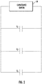
- the capacitance measured by the capacitance sensor 14 represents an effective capacitance C eff that is based on a first capacitance C 1 between the wall 22 and siphon tube 32 with the pressurant 38 as a dielectric medium, a second capacitance C 2 between the wall 22 and siphon tube 32 with the suppressant 36 as a dielectric medium, and a stray capacitance C S of each of the wall 22 and siphon tube 32, as shown in equation (1) below.
- C eff C 1 + C 2 + C S
- Figure 2 schematically illustrates the capacitance values C 1 , C 2 , and C S .
- the capacitances C 1 and C 2 can be calculated using equations (2)-(3) below.
- C 1 2 ⁇ ⁇ 1 l 1 ln R 2
- C 2 2 ⁇ ⁇ 2 l 2 ln R 2 R 1
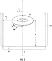
- Figure 3 schematically illustrates the second end 35B of the siphon tube 32 as a toroidal ring, along with parameters R 1 and R 2 from equations 1-2 above.
- the stray capacitance C S is based on a size of the gap G between the second end 35B of the siphon tube 32 and the base portion 30 of the wall 22, and can be calculated using equation (4) below, which considers the end 35B of the siphon tube 32 as a circular toroidal ring (as shown in Figure 3 ).
- C S 4 ⁇ 2 ⁇ 2 R ln 8 ⁇ R a ⁇ K k 2 ⁇ k
- C S C 3 ⁇ C 4 C 3 + C 4
- the processor 18 is configured to determine the amount of suppressant 36 in the inner chamber 24 based on a predefined mapping between capacitance values and suppressant amounts for the cylinder 12.
- a predefined mapping is provided below in Table 1, which maps suppressant levels to corresponding effective capacitance values in picofarads for the suppressant Novec 1230 in a 125 pound cylinder. As shown in the table, the effective capacitance varies with the suppressant level, with decreasing suppressant levels yielding decreased effective capacitance values.
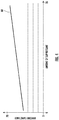
- Figure 4 is a graph that plots the values of Figure 4 , and demonstrates how the relationship between effective capacitance and suppressant level, shown on plot 60, is generally linear.
- Another example mapping could map capacitance values to suppressant weight values in the inner chamber 24.
- the system described herein confers a number of benefits, including suitability for both seamless and welded fire suppression cylinders. Also, because little modification is needed to the current infrastructure for fire suppression cylinders, the system described herein is well-suited for retrofitting into existing suppression cylinders.
- the linearity in sensing shown in Figure 4 provides for reliable sensing, and using the wall 22 and siphon tube 32 as electrodes provides for improved sensor life as compared to prior art sensors. Still further, the detection system 10 provides for convenient real time monitoring.
Landscapes
- Engineering & Computer Science (AREA)
- Physics & Mathematics (AREA)
- Health & Medical Sciences (AREA)
- Power Engineering (AREA)
- Emergency Management (AREA)
- Business, Economics & Management (AREA)
- Public Health (AREA)
- Electromagnetism (AREA)
- General Engineering & Computer Science (AREA)
- Mechanical Engineering (AREA)
- General Physics & Mathematics (AREA)
- Fluid Mechanics (AREA)
- Thermal Sciences (AREA)
- Measurement Of Levels Of Liquids Or Fluent Solid Materials (AREA)
Abstract
Description
- The present invention relates to a fire suppression system, and to a method for detecting an amount of suppressant in a fire suppression cylinder.
- A "clean agent" is a type of fire suppressant. A clean agent fire suppression system extinguishes fires by creating a fire extinguishing atmosphere consisting of agent vapor or gas mixed with the air within the protected space. Clean agent systems may be used in buildings and other such structures and areas to suppress fires without water, powder or foam so not as to destroy or damage an enclosed area of the structure and/or equipment contained therein.
- Sensors like magnetic float and reed switch based techniques are currently used to determine the level of clean agent present in a suppression cylinder. However, these devices have traditionally only been useful for welded, not seamless, cylinders, and the process of determining the level of clean agent based on readings from these devices is tedious.
- Viewed from a first aspect, the invention provides a fire suppression system comprising: a cylinder having a wall defining an inner chamber, and a processor operable to determine an amount of a suppressant in the inner chamber based on a capacitance between a first electrode and a second electrode that are both in contact with the suppressant.
- Optionally, each of the first electrode and second electrode are also in contact with a pressurant in the inner chamber.
- Optionally, the capacitance has an effective capacitance based on a first capacitance between the first and second electrodes with the suppressant as a dielectric medium, and a second capacitance between the first and second electrodes with the pressurant as a dielectric medium.
- Optionally, a siphon tube is disposed within the inner chamber and is spaced apart from the wall. One of the first and second electrodes includes the siphon tube, and the other of the first and second electrodes includes the wall.
- Optionally, the siphon tube and cylinder are concentric.
- Optionally, the effective capacitance is also based on a stray capacitance of each of the siphon tube and the wall.
- Optionally, the siphon tube includes opposing first and second ends, the first end coupled to an output of the cylinder, the second end proximate to a base portion of the wall, the cylinder including a gap between the second end and the base portion, the stray capacitance indicative of a size of the gap.
- Optionally, the determination of the amount of suppressant in the inner chamber is based on, a radius of the siphon tube, a radius of the cylinder, a dielectric constant of the suppressant, a dielectric constant of the pressurant, and a size of the gap between the base portion of the cylinder and the second end of the siphon tube.
- Optionally, the processor is operable to determine the amount of suppressant in the inner chamber based on a predefined mapping between capacitance values and suppressant amounts for the cylinder.
- Optionally, the processor is operable to display an indication of the amount of suppressant on an electronic display.
- Optionally, a measuring circuit is operable to measure the capacitance between the first and second electrodes and provide the measured capacitance to the processor.
- Viewed from a second aspect, the invention provides a method for determining an amount of suppressant in a cylinder comprising: measuring a capacitance between a first electrode and a second electrode that are both in contact with a suppressant within a cylinder, and determining an amount of suppressant within the cylinder based on the capacitance.
- Optionally, each of the first electrode and second electrode is also in contact with a pressurant within the cylinder.
- Optionally, the capacitance is an effective capacitance based on a first capacitance between the first and second electrodes with the suppressant as a dielectric medium, and a second capacitance between the first and second electrodes with the pressurant as a dielectric medium.
- Optionally, the effective capacitance is also based on a stray capacitance of each of the first and second electrodes.
- Optionally, measuring a capacitance between a first electrode and a second electrode includes utilizing a wall of the cylinder as one of the first and second electrodes, and utilizing a siphon tube disposed within the cylinder as the other of the first and second electrodes.
- Optionally, determining an amount of suppressant within the cylinder is based on each of the following: a radius of the siphon tube, a radius of the cylinder, a dielectric constant of the suppressant, a dielectric constant of the pressurant, and a size of a gap between a base portion of the cylinder and an end of the siphon tube.
- Optionally, determining an amount of the suppressant within the cylinder based on the capacitance is performed using a predefined mapping between capacitance values and suppressant amounts for the cylinder.
- A fire suppression system according to an example of the present disclosure includes a cylinder comprising a wall defining an inner chamber, a siphon tube disposed within the inner chamber and spaced apart from the wall, and a processor operable to determine a level of suppressant in the inner chamber based on a capacitance between the wall and the siphon tube.
- Optionally, the capacitance is an effective capacitance based on a first capacitance between the siphon tube and wall with the suppressant as a dielectric medium, and a second capacitance between the siphon tube and wall with a pressurant as a dielectric medium.
- The embodiments, examples, and alternatives of the preceding paragraphs, the claims, or the following description and drawings, including any of their various aspects or respective individual features, may be taken independently or in any combination. Features described in connection with one embodiment are applicable to all embodiments, unless such features are incompatible.
-
Figure 1 is a schematic view of an example fire suppression system. -
Figure 2 is a schematic view of a plurality of capacitances of the fire suppression system. -
Figure 3 schematically illustrates an end of a siphon tube of the fire suppression system as a toroidal ring. -
Figure 4 is a graph plotting example capacitance values for example suppressant levels. -
Figure 1 is a schematic view of an examplefire suppression system 10 that is operable to determine a level of suppressant within acylinder 12 based on capacitive sensing. Thefire suppression system 10 includes thecylinder 12, acapacitance sensor 14, asignal processing circuit 16, aprocessor 18, and anelectronic display 20. - The
cylinder 12 includes awall 22 defining aninner chamber 24. Thecylinder 12 has opposing first andsecond ends 26A-B. Acontrol head 28 is disposed at thefirst end 26A of thecylinder 12, and abase portion 30 of thewall 22 is disposed at thesecond end 26B of thecylinder 12. - A
siphon tube 32 is disposed within thecylinder 12 and provides for fluid communication between theinner chamber 24 and anoutput valve 34 in thecontrol head 28. Thesiphon tube 32 is spaced away from thewall 22. Thesiphon tube 32 includes opposing first andsecond ends 35A-B. Thefirst end 35A is proximate to thecontrol head 28 and thesecond end 35B is proximate to thebase portion 30 of thewall 22. A cap G is formed between thesecond end 35B of thesiphon tube 32 and thebase portion 30 of thewall 22. In the example ofFigure 1 , thewall 22 andsiphon tube 32 are concentric and share a same central longitudinal axis A. - Within the
inner chamber 24, a suppressant 36 is disposed beneath a pressurant 38. The pressurant 38 is a gas, such as nitrogen, that pressurizes the suppressant 36, and causes the suppressant 36 to travel through thesiphon tube 32 and through thevalve 34 upon opening of thevalve 34. Theoutput valve 34 may be fluidly connected to anoutput channel 40, such as an output manifold, for dispensing the suppressant 36. The suppressant 36 can be a clean agent (e.g., Novec 1230), a wet chemical, or a dry chemical, for example. Thewall 22 andsiphon tube 32 are each in contact with both of the suppressant 36 and the pressurant 38 in theinner chamber 24. A height of the pressurant 38 in thecylinder 12 is represented by length ℓ1, and a height of the suppressant 36 within thecylinder 12 is represented by length ℓ2. - The
wall 22 of thecylinder 12 and thesiphon tube 32 are both electrically conductive, and because of their relative proximity to each other, and the suppressant 36 and pressurant 38 between them, thewall 22 andsiphon tube 32 can each operate as an electrode of a capacitor. If a voltage difference is applied between thewall 22 andsiphon tube 32, an electric field is formed therebetween, and a fringing effect of the electric field lines is produced. - The suppressant 36 and pressurant 38 have different dielectric constants (ε1 for the pressurant 38 and ε2 for the suppressant 36) and act as separate dielectric mediums. As the amount of suppressant 36 in the
cylinder 12 is lowered (e.g., through suppressant dispensing), the pressurant 38 gas displaces thesuppressant 36 and changes the capacitance between thewall 22 andsiphon tube 32. - The
capacitance sensor 14 is operable to measure a capacitance between thewall 22 andsiphon tube 32, and provide a signal indicative of that capacitance tosignal processing circuit 16. Thesignal processing circuit 16 processes that signal (e.g., by filtering and/or amplifying the signal) and provides a processed signal to theprocessor 18, which determines an amount of suppressant 36 in theinner chamber 24 based on the capacitance between thewall 22 andsiphon tube 32. - The
processor 18 is operable to display an indication of the amount of suppressant 36 within thecylinder 12 on anelectronic display 20, which may be an organic light-emitting diode (OLED) display, for example. The indication could include a color corresponding to the level (e.g., green for a first amount of suppressant 36, yellow for a second, smaller amount of suppressant 36, and red for a third, even smaller amount of suppressant 36). In one example the suppressant amount is indicated as a height of the suppressant 36 within the inner chamber 22 (e.g., magnitude of ℓ2) and/or a weight of the suppressant 36 within theinner chamber 22. - The
processor 18 can be a microcontroller, microprocessor, application-specific integrated circuit (ASIC), or the like. - The capacitance measured by the
capacitance sensor 14 represents an effective capacitance Ceff that is based on a first capacitance C1 between thewall 22 andsiphon tube 32 with the pressurant 38 as a dielectric medium, a second capacitance C2 between thewall 22 andsiphon tube 32 with the suppressant 36 as a dielectric medium, and a stray capacitance CS of each of thewall 22 andsiphon tube 32, as shown in equation (1) below.
Figure 2 schematically illustrates the capacitance values C1, C2, and CS. The capacitances C1 and C2 can be calculated using equations (2)-(3) below.

- where ε1 is the dielectric constant of the pressurant 38;
- ε2 is the dielectric constant of the suppressant 36;
- R1 is an inner radius of the
cylinder 12; - R2 is an outer radius of the siphon
tube 32; - ℓ1 is the height of the
pressurant 38 within thecylinder 12; and - ℓ2 is the height of the
suppressant 36 within thecylinder 12. -
Figure 3 schematically illustrates thesecond end 35B of the siphontube 32 as a toroidal ring, along with parameters R1 and R2 from equations 1-2 above. - The stray capacitance CS is based on a size of the gap G between the
second end 35B of the siphontube 32 and thebase portion 30 of thewall 22, and can be calculated using equation (4) below, which considers theend 35B of the siphontube 32 as a circular toroidal ring (as shown inFigure 3 ).
- where: K is an elliptical integral of the first kind;
- k is a constant that can be calculated using equation (5) below; and
- a is an inner radius of the siphon
tube 32. - where: R is equivalent to the outer radius R 2 of the siphon
tube 32; and - h is a size of the gap G.
- Another way of representing the stray capacitance CS is based on its constituent components C3 which represents a stray capacitance of the
wall 22, and C4 which represents a stray capacitance of the siphontube 32, as shown in equation (6) below.
- Another way of representing the effective capacitance Ceff is with equation (5) below.

- where: C1 and C2 are the same as described above;
- C3 is a stray capacitance of the
wall 22; and - C4 is a stray capacitance of the siphon
tube 32. - In one example, the
processor 18 is configured to determine the amount ofsuppressant 36 in theinner chamber 24 based on a predefined mapping between capacitance values and suppressant amounts for thecylinder 12. One example mapping is provided below in Table 1, which maps suppressant levels to corresponding effective capacitance values in picofarads for the suppressant Novec 1230 in a 125 pound cylinder. As shown in the table, the effective capacitance varies with the suppressant level, with decreasing suppressant levels yielding decreased effective capacitance values.Table 1 Suppressant level in inches Effective capacitance in pF Suppressant level in inches Effective capacitance in pF 1 38.67 17 52.39 2 39.52 18 53.24 3 40.38 19 54.1 4 41.24 20 54.96 5 42.1 21 55.82 6 42.95 22 6.67 7 43.81 23 57.53 8 44.67 24 58.39 9 45.53 25 59.25 10 46.38 26 60.1 11 47.24 27 60.96 12 48.1 28 61.82 13 48.96 29 62.68 14 49.81 30 63.53 15 50.67 31 64.39 16 51.53 32 65.25 -
Figure 4 is a graph that plots the values ofFigure 4 , and demonstrates how the relationship between effective capacitance and suppressant level, shown on plot 60, is generally linear. - Another example mapping could map capacitance values to suppressant weight values in the
inner chamber 24. - Although the
cylinder 12 and the siphontube 32 have been discussed as example electrodes for the sensing technique discussed above, it is understood that these are only examples, and that other electrodes could be used if desired. - The system described herein confers a number of benefits, including suitability for both seamless and welded fire suppression cylinders. Also, because little modification is needed to the current infrastructure for fire suppression cylinders, the system described herein is well-suited for retrofitting into existing suppression cylinders. The linearity in sensing shown in
Figure 4 provides for reliable sensing, and using thewall 22 and siphontube 32 as electrodes provides for improved sensor life as compared to prior art sensors. Still further, thedetection system 10 provides for convenient real time monitoring. - Although example embodiments have been disclosed, a worker of ordinary skill in this art would recognize that certain modifications would come within the scope of the invention, as defined by the claims. For that reason, the following claims should be studied to determine the scope of the invention.

Claims (14)
- A fire suppression system, comprising:a cylinder having a wall defining an inner chamber; anda processor operable to determine an amount of a suppressant in the inner chamber based on a capacitance between a first electrode and a second electrode that are both in contact with the suppressant.
- The fire suppression system of claim 1, wherein each of the first electrode and second electrode is also in contact with a pressurant in the inner chamber.
- The fire suppression system of claim 2, wherein the capacitance is an effective capacitance based on a first capacitance between the first and second electrodes with the suppressant as a dielectric medium, and a second capacitance between the first and second electrodes with the pressurant as a dielectric medium.
- The fire suppression system of claim 1, 2 or 3, comprising:a siphon tube disposed within the inner chamber and spaced apart from the wall;wherein one of the first and second electrodes includes the siphon tube, and the other of the first and second electrodes includes the wall.
- The fire suppression system of claim 4, wherein the siphon tube and cylinder are concentric.
- The fire suppression system of claim 4 or 5, wherein the effective capacitance is also based on a stray capacitance of each of the siphon tube and the wall.
- The fire suppression system of claim 6, wherein the siphon tube comprises opposing first and second ends, the first end coupled to an output of the cylinder, the second end proximate to a base portion of the wall, the cylinder including a gap between the second end and the base portion, the stray capacitance indicative of a size of the gap.
- The fire suppression system of claim 7, wherein the determination of the amount of suppressant in the inner chamber is based on:a radius of the siphon tube;a radius of the cylinder;a dielectric constant of the suppressant;a dielectric constant of the pressurant; anda size of the gap between the base portion of the cylinder and the second end of the siphon tube.
- The fire suppression system of any preceding claim, wherein the processor is operable to determine the amount of suppressant in the inner chamber based on a predefined mapping between capacitance values and suppressant amounts for the cylinder.
- The fire suppression system of any preceding claim, comprising an electronic display, the processor operable to display an indication of the amount of suppressant on the electronic display.
- The fire suppression system of any preceding claim, comprising a measuring circuit operable to measure the capacitance between the first and second electrodes and provide the measured capacitance to the processor.
- A method for determining an amount of suppressant in a cylinder, comprising:measuring a capacitance between a first electrode and a second electrode that are both in contact with a suppressant within the cylinder; anddetermining an amount of suppressant within the cylinder based on the capacitance.
- The method of claim 12, using the fire suppression system of any preceding claim.
- The method of claim 12 or 13, wherein said step of determining an amount of the suppressant within the cylinder based on the capacitance is performed using a predefined mapping between capacitance values and suppressant amounts for the cylinder.
Applications Claiming Priority (1)
| Application Number | Priority Date | Filing Date | Title |
|---|---|---|---|
| IN201911007926 | 2019-02-28 |
Publications (2)
| Publication Number | Publication Date |
|---|---|
| EP3702662A1 true EP3702662A1 (en) | 2020-09-02 |
| EP3702662B1 EP3702662B1 (en) | 2022-09-14 |
Family
ID=69953728
Family Applications (1)
| Application Number | Title | Priority Date | Filing Date |
|---|---|---|---|
| EP20159312.6A Active EP3702662B1 (en) | 2019-02-28 | 2020-02-25 | Fire suppressant system |
Country Status (2)
| Country | Link |
|---|---|
| EP (1) | EP3702662B1 (en) |
| CA (1) | CA3071170C (en) |
Cited By (1)
| Publication number | Priority date | Publication date | Assignee | Title |
|---|---|---|---|---|
| CN119713128A (en) * | 2024-12-23 | 2025-03-28 | 江苏荣夏安全科技有限公司 | Explosion-proof steel bottle with intelligent early warning monitoring function |
Families Citing this family (1)
| Publication number | Priority date | Publication date | Assignee | Title |
|---|---|---|---|---|
| US20250108244A1 (en) * | 2023-10-03 | 2025-04-03 | Kidde Technologies, Inc. | Powder level detection system |
Citations (3)
| Publication number | Priority date | Publication date | Assignee | Title |
|---|---|---|---|---|
| DE3731793A1 (en) * | 1987-09-22 | 1989-03-30 | Total Feuerschutz Gmbh | Fire-extinguishing equipment |
| US20040164868A1 (en) * | 2000-08-10 | 2004-08-26 | Andreas Thomas | Carbon dioxide fire extinguishing device |
| US20170199070A1 (en) * | 2016-01-12 | 2017-07-13 | Wilhelm BAYERL | Cylinder for pressurised liquefied gas and a method of calculating the liquid volume |
-
2020
- 2020-02-04 CA CA3071170A patent/CA3071170C/en active Active
- 2020-02-25 EP EP20159312.6A patent/EP3702662B1/en active Active
Patent Citations (3)
| Publication number | Priority date | Publication date | Assignee | Title |
|---|---|---|---|---|
| DE3731793A1 (en) * | 1987-09-22 | 1989-03-30 | Total Feuerschutz Gmbh | Fire-extinguishing equipment |
| US20040164868A1 (en) * | 2000-08-10 | 2004-08-26 | Andreas Thomas | Carbon dioxide fire extinguishing device |
| US20170199070A1 (en) * | 2016-01-12 | 2017-07-13 | Wilhelm BAYERL | Cylinder for pressurised liquefied gas and a method of calculating the liquid volume |
Cited By (1)
| Publication number | Priority date | Publication date | Assignee | Title |
|---|---|---|---|---|
| CN119713128A (en) * | 2024-12-23 | 2025-03-28 | 江苏荣夏安全科技有限公司 | Explosion-proof steel bottle with intelligent early warning monitoring function |
Also Published As
| Publication number | Publication date |
|---|---|
| CA3071170A1 (en) | 2020-08-28 |
| CA3071170C (en) | 2022-04-12 |
| EP3702662B1 (en) | 2022-09-14 |
Similar Documents
| Publication | Publication Date | Title |
|---|---|---|
| EP3702662B1 (en) | Fire suppressant system | |
| JP6251736B2 (en) | Capacitive level sensor | |
| CA2950965A1 (en) | Method and apparatus for monitoring fill level of a medium in a container | |
| EP1745310B1 (en) | Auto-deep scan for capacitive sensing | |
| RU2003105807A (en) | CARBON ACID FIRE FIGHTING DEVICE | |
| JPH035863Y2 (en) | ||
| CA3168409C (en) | Capacitive filling level probe without dead zone | |
| US11385092B2 (en) | Suppressant detection based on capacitive sensing | |
| US20250164426A1 (en) | Compensated conductivity determination | |
| JP3691839B1 (en) | Capacitively coupled sensor device | |
| US9395226B2 (en) | Apparatus for determining and/or monitoring a process variable | |
| EP3599447B1 (en) | Dielectric-constant-insensitive fluid level sensor for directly inserting into a high dielectric constant fluid | |
| JP2007064933A (en) | Correction method for liquid level detection device and liquid level detection device | |
| EP0057278B1 (en) | Capacitance circuit for level measurement | |
| US20190027275A1 (en) | Sensor Line | |
| JP4782506B2 (en) | Capacitive sensor | |
| US20030169036A1 (en) | Sensor arrangement for detecting properties of a target | |
| GB2218812A (en) | A capacitive apparatus for measuring liquid volume and flow rate | |
| CN118661079A (en) | Method and device for monitoring the fill level of a medium in a container | |
| KR101725157B1 (en) | Conductive-Material detector using electric capacitive sensor | |
| JP4998493B2 (en) | Mixing ratio calculation device and mixing ratio calculation method using the mixing ratio calculation device | |
| JPH0933317A (en) | Capacitance sensor | |
| WO2007079516A3 (en) | Sensor device and method for monitoring a fuel cell system | |
| JP4131162B2 (en) | Oil detection device | |
| US20090126484A1 (en) | Device and method for detecting the filling level of a container, and device for filling a container |
Legal Events
| Date | Code | Title | Description |
|---|---|---|---|
| PUAI | Public reference made under article 153(3) epc to a published international application that has entered the european phase |
Free format text: ORIGINAL CODE: 0009012 |
|
| STAA | Information on the status of an ep patent application or granted ep patent |
Free format text: STATUS: THE APPLICATION HAS BEEN PUBLISHED |
|
| AK | Designated contracting states |
Kind code of ref document: A1 Designated state(s): AL AT BE BG CH CY CZ DE DK EE ES FI FR GB GR HR HU IE IS IT LI LT LU LV MC MK MT NL NO PL PT RO RS SE SI SK SM TR |
|
| AX | Request for extension of the european patent |
Extension state: BA ME |
|
| STAA | Information on the status of an ep patent application or granted ep patent |
Free format text: STATUS: REQUEST FOR EXAMINATION WAS MADE |
|
| 17P | Request for examination filed |
Effective date: 20210223 |
|
| RBV | Designated contracting states (corrected) |
Designated state(s): AL AT BE BG CH CY CZ DE DK EE ES FI FR GB GR HR HU IE IS IT LI LT LU LV MC MK MT NL NO PL PT RO RS SE SI SK SM TR |
|
| GRAP | Despatch of communication of intention to grant a patent |
Free format text: ORIGINAL CODE: EPIDOSNIGR1 |
|
| STAA | Information on the status of an ep patent application or granted ep patent |
Free format text: STATUS: GRANT OF PATENT IS INTENDED |
|
| RIC1 | Information provided on ipc code assigned before grant |
Ipc: G01F 23/263 20220101ALI20220331BHEP Ipc: G01F 23/26 20060101ALI20220331BHEP Ipc: A62C 37/50 20060101ALI20220331BHEP Ipc: A62C 35/13 20060101ALI20220331BHEP Ipc: F17C 13/02 20060101AFI20220331BHEP |
|
| INTG | Intention to grant announced |
Effective date: 20220425 |
|
| GRAS | Grant fee paid |
Free format text: ORIGINAL CODE: EPIDOSNIGR3 |
|
| GRAA | (expected) grant |
Free format text: ORIGINAL CODE: 0009210 |
|
| STAA | Information on the status of an ep patent application or granted ep patent |
Free format text: STATUS: THE PATENT HAS BEEN GRANTED |
|
| AK | Designated contracting states |
Kind code of ref document: B1 Designated state(s): AL AT BE BG CH CY CZ DE DK EE ES FI FR GB GR HR HU IE IS IT LI LT LU LV MC MK MT NL NO PL PT RO RS SE SI SK SM TR |
|
| REG | Reference to a national code |
Ref country code: GB Ref legal event code: FG4D |
|
| REG | Reference to a national code |
Ref country code: CH Ref legal event code: EP |
|
| REG | Reference to a national code |
Ref country code: DE Ref legal event code: R096 Ref document number: 602020005051 Country of ref document: DE |
|
| REG | Reference to a national code |
Ref country code: IE Ref legal event code: FG4D |
|
| REG | Reference to a national code |
Ref country code: AT Ref legal event code: REF Ref document number: 1518895 Country of ref document: AT Kind code of ref document: T Effective date: 20221015 |
|
| REG | Reference to a national code |
Ref country code: LT Ref legal event code: MG9D |
|
| REG | Reference to a national code |
Ref country code: NL Ref legal event code: MP Effective date: 20220914 |
|
| PG25 | Lapsed in a contracting state [announced via postgrant information from national office to epo] |
Ref country code: SE Free format text: LAPSE BECAUSE OF FAILURE TO SUBMIT A TRANSLATION OF THE DESCRIPTION OR TO PAY THE FEE WITHIN THE PRESCRIBED TIME-LIMIT Effective date: 20220914 Ref country code: RS Free format text: LAPSE BECAUSE OF FAILURE TO SUBMIT A TRANSLATION OF THE DESCRIPTION OR TO PAY THE FEE WITHIN THE PRESCRIBED TIME-LIMIT Effective date: 20220914 Ref country code: NO Free format text: LAPSE BECAUSE OF FAILURE TO SUBMIT A TRANSLATION OF THE DESCRIPTION OR TO PAY THE FEE WITHIN THE PRESCRIBED TIME-LIMIT Effective date: 20221214 Ref country code: LV Free format text: LAPSE BECAUSE OF FAILURE TO SUBMIT A TRANSLATION OF THE DESCRIPTION OR TO PAY THE FEE WITHIN THE PRESCRIBED TIME-LIMIT Effective date: 20220914 Ref country code: LT Free format text: LAPSE BECAUSE OF FAILURE TO SUBMIT A TRANSLATION OF THE DESCRIPTION OR TO PAY THE FEE WITHIN THE PRESCRIBED TIME-LIMIT Effective date: 20220914 Ref country code: FI Free format text: LAPSE BECAUSE OF FAILURE TO SUBMIT A TRANSLATION OF THE DESCRIPTION OR TO PAY THE FEE WITHIN THE PRESCRIBED TIME-LIMIT Effective date: 20220914 |
|
| REG | Reference to a national code |
Ref country code: AT Ref legal event code: MK05 Ref document number: 1518895 Country of ref document: AT Kind code of ref document: T Effective date: 20220914 |
|
| PG25 | Lapsed in a contracting state [announced via postgrant information from national office to epo] |
Ref country code: HR Free format text: LAPSE BECAUSE OF FAILURE TO SUBMIT A TRANSLATION OF THE DESCRIPTION OR TO PAY THE FEE WITHIN THE PRESCRIBED TIME-LIMIT Effective date: 20220914 Ref country code: GR Free format text: LAPSE BECAUSE OF FAILURE TO SUBMIT A TRANSLATION OF THE DESCRIPTION OR TO PAY THE FEE WITHIN THE PRESCRIBED TIME-LIMIT Effective date: 20221215 |
|
| PG25 | Lapsed in a contracting state [announced via postgrant information from national office to epo] |
Ref country code: SM Free format text: LAPSE BECAUSE OF FAILURE TO SUBMIT A TRANSLATION OF THE DESCRIPTION OR TO PAY THE FEE WITHIN THE PRESCRIBED TIME-LIMIT Effective date: 20220914 Ref country code: RO Free format text: LAPSE BECAUSE OF FAILURE TO SUBMIT A TRANSLATION OF THE DESCRIPTION OR TO PAY THE FEE WITHIN THE PRESCRIBED TIME-LIMIT Effective date: 20220914 Ref country code: PT Free format text: LAPSE BECAUSE OF FAILURE TO SUBMIT A TRANSLATION OF THE DESCRIPTION OR TO PAY THE FEE WITHIN THE PRESCRIBED TIME-LIMIT Effective date: 20230116 Ref country code: ES Free format text: LAPSE BECAUSE OF FAILURE TO SUBMIT A TRANSLATION OF THE DESCRIPTION OR TO PAY THE FEE WITHIN THE PRESCRIBED TIME-LIMIT Effective date: 20220914 Ref country code: CZ Free format text: LAPSE BECAUSE OF FAILURE TO SUBMIT A TRANSLATION OF THE DESCRIPTION OR TO PAY THE FEE WITHIN THE PRESCRIBED TIME-LIMIT Effective date: 20220914 Ref country code: AT Free format text: LAPSE BECAUSE OF FAILURE TO SUBMIT A TRANSLATION OF THE DESCRIPTION OR TO PAY THE FEE WITHIN THE PRESCRIBED TIME-LIMIT Effective date: 20220914 |
|
| PG25 | Lapsed in a contracting state [announced via postgrant information from national office to epo] |
Ref country code: SK Free format text: LAPSE BECAUSE OF FAILURE TO SUBMIT A TRANSLATION OF THE DESCRIPTION OR TO PAY THE FEE WITHIN THE PRESCRIBED TIME-LIMIT Effective date: 20220914 Ref country code: PL Free format text: LAPSE BECAUSE OF FAILURE TO SUBMIT A TRANSLATION OF THE DESCRIPTION OR TO PAY THE FEE WITHIN THE PRESCRIBED TIME-LIMIT Effective date: 20220914 Ref country code: IS Free format text: LAPSE BECAUSE OF FAILURE TO SUBMIT A TRANSLATION OF THE DESCRIPTION OR TO PAY THE FEE WITHIN THE PRESCRIBED TIME-LIMIT Effective date: 20230114 Ref country code: EE Free format text: LAPSE BECAUSE OF FAILURE TO SUBMIT A TRANSLATION OF THE DESCRIPTION OR TO PAY THE FEE WITHIN THE PRESCRIBED TIME-LIMIT Effective date: 20220914 |
|
| REG | Reference to a national code |
Ref country code: DE Ref legal event code: R097 Ref document number: 602020005051 Country of ref document: DE |
|
| PG25 | Lapsed in a contracting state [announced via postgrant information from national office to epo] |
Ref country code: NL Free format text: LAPSE BECAUSE OF FAILURE TO SUBMIT A TRANSLATION OF THE DESCRIPTION OR TO PAY THE FEE WITHIN THE PRESCRIBED TIME-LIMIT Effective date: 20220914 Ref country code: AL Free format text: LAPSE BECAUSE OF FAILURE TO SUBMIT A TRANSLATION OF THE DESCRIPTION OR TO PAY THE FEE WITHIN THE PRESCRIBED TIME-LIMIT Effective date: 20220914 |
|
| PLBE | No opposition filed within time limit |
Free format text: ORIGINAL CODE: 0009261 |
|
| STAA | Information on the status of an ep patent application or granted ep patent |
Free format text: STATUS: NO OPPOSITION FILED WITHIN TIME LIMIT |
|
| PG25 | Lapsed in a contracting state [announced via postgrant information from national office to epo] |
Ref country code: DK Free format text: LAPSE BECAUSE OF FAILURE TO SUBMIT A TRANSLATION OF THE DESCRIPTION OR TO PAY THE FEE WITHIN THE PRESCRIBED TIME-LIMIT Effective date: 20220914 |
|
| 26N | No opposition filed |
Effective date: 20230615 |
|
| PG25 | Lapsed in a contracting state [announced via postgrant information from national office to epo] |
Ref country code: SI Free format text: LAPSE BECAUSE OF FAILURE TO SUBMIT A TRANSLATION OF THE DESCRIPTION OR TO PAY THE FEE WITHIN THE PRESCRIBED TIME-LIMIT Effective date: 20220914 |
|
| PG25 | Lapsed in a contracting state [announced via postgrant information from national office to epo] |
Ref country code: MC Free format text: LAPSE BECAUSE OF FAILURE TO SUBMIT A TRANSLATION OF THE DESCRIPTION OR TO PAY THE FEE WITHIN THE PRESCRIBED TIME-LIMIT Effective date: 20220914 |
|
| REG | Reference to a national code |
Ref country code: CH Ref legal event code: PL |
|
| REG | Reference to a national code |
Ref country code: BE Ref legal event code: MM Effective date: 20230228 |
|
| PG25 | Lapsed in a contracting state [announced via postgrant information from national office to epo] |
Ref country code: LU Free format text: LAPSE BECAUSE OF NON-PAYMENT OF DUE FEES Effective date: 20230225 Ref country code: LI Free format text: LAPSE BECAUSE OF NON-PAYMENT OF DUE FEES Effective date: 20230228 Ref country code: CH Free format text: LAPSE BECAUSE OF NON-PAYMENT OF DUE FEES Effective date: 20230228 |
|
| REG | Reference to a national code |
Ref country code: IE Ref legal event code: MM4A |
|
| PG25 | Lapsed in a contracting state [announced via postgrant information from national office to epo] |
Ref country code: IE Free format text: LAPSE BECAUSE OF NON-PAYMENT OF DUE FEES Effective date: 20230225 |
|
| PG25 | Lapsed in a contracting state [announced via postgrant information from national office to epo] |
Ref country code: BE Free format text: LAPSE BECAUSE OF NON-PAYMENT OF DUE FEES Effective date: 20230228 |
|
| PG25 | Lapsed in a contracting state [announced via postgrant information from national office to epo] |
Ref country code: IT Free format text: LAPSE BECAUSE OF FAILURE TO SUBMIT A TRANSLATION OF THE DESCRIPTION OR TO PAY THE FEE WITHIN THE PRESCRIBED TIME-LIMIT Effective date: 20220914 |
|
| REG | Reference to a national code |
Ref country code: GB Ref legal event code: 732E Free format text: REGISTERED BETWEEN 20241003 AND 20241009 |
|
| REG | Reference to a national code |
Ref country code: GB Ref legal event code: 732E Free format text: REGISTERED BETWEEN 20241010 AND 20241016 |
|
| PG25 | Lapsed in a contracting state [announced via postgrant information from national office to epo] |
Ref country code: BG Free format text: LAPSE BECAUSE OF FAILURE TO SUBMIT A TRANSLATION OF THE DESCRIPTION OR TO PAY THE FEE WITHIN THE PRESCRIBED TIME-LIMIT Effective date: 20220914 |
|
| REG | Reference to a national code |
Ref country code: DE Ref legal event code: R081 Ref document number: 602020005051 Country of ref document: DE Owner name: KIDDE-FENWAL, LLC (N. D. GES. D. STAATES DELAW, US Free format text: FORMER OWNER: CARRIER CORPORATION, PALM BEACH GARDENS, FL, US |
|
| PG25 | Lapsed in a contracting state [announced via postgrant information from national office to epo] |
Ref country code: BG Free format text: LAPSE BECAUSE OF FAILURE TO SUBMIT A TRANSLATION OF THE DESCRIPTION OR TO PAY THE FEE WITHIN THE PRESCRIBED TIME-LIMIT Effective date: 20220914 |
|
| PG25 | Lapsed in a contracting state [announced via postgrant information from national office to epo] |
Ref country code: CY Free format text: LAPSE BECAUSE OF FAILURE TO SUBMIT A TRANSLATION OF THE DESCRIPTION OR TO PAY THE FEE WITHIN THE PRESCRIBED TIME-LIMIT; INVALID AB INITIO Effective date: 20200225 |
|
| PG25 | Lapsed in a contracting state [announced via postgrant information from national office to epo] |
Ref country code: HU Free format text: LAPSE BECAUSE OF FAILURE TO SUBMIT A TRANSLATION OF THE DESCRIPTION OR TO PAY THE FEE WITHIN THE PRESCRIBED TIME-LIMIT; INVALID AB INITIO Effective date: 20200225 |
|
| PG25 | Lapsed in a contracting state [announced via postgrant information from national office to epo] |
Ref country code: TR Free format text: LAPSE BECAUSE OF FAILURE TO SUBMIT A TRANSLATION OF THE DESCRIPTION OR TO PAY THE FEE WITHIN THE PRESCRIBED TIME-LIMIT Effective date: 20220914 |
|
| PGFP | Annual fee paid to national office [announced via postgrant information from national office to epo] |
Ref country code: FR Payment date: 20251231 Year of fee payment: 7 |
|
| PGFP | Annual fee paid to national office [announced via postgrant information from national office to epo] |
Ref country code: GB Payment date: 20260106 Year of fee payment: 7 |
|
| PGFP | Annual fee paid to national office [announced via postgrant information from national office to epo] |
Ref country code: DE Payment date: 20260102 Year of fee payment: 7 |