EP3702617A1 - Variable displacement reciprocating piston unit generating piston stroke speed and piston stroke length signal - Google Patents
Variable displacement reciprocating piston unit generating piston stroke speed and piston stroke length signal Download PDFInfo
- Publication number
- EP3702617A1 EP3702617A1 EP19159899.4A EP19159899A EP3702617A1 EP 3702617 A1 EP3702617 A1 EP 3702617A1 EP 19159899 A EP19159899 A EP 19159899A EP 3702617 A1 EP3702617 A1 EP 3702617A1
- Authority
- EP
- European Patent Office
- Prior art keywords
- target
- piston
- sensor probe
- calibration
- stroke length
- Prior art date
- Legal status (The legal status is an assumption and is not a legal conclusion. Google has not performed a legal analysis and makes no representation as to the accuracy of the status listed.)
- Granted
Links
Images



Classifications
-
- F—MECHANICAL ENGINEERING; LIGHTING; HEATING; WEAPONS; BLASTING
- F04—POSITIVE - DISPLACEMENT MACHINES FOR LIQUIDS; PUMPS FOR LIQUIDS OR ELASTIC FLUIDS
- F04B—POSITIVE-DISPLACEMENT MACHINES FOR LIQUIDS; PUMPS
- F04B1/00—Multi-cylinder machines or pumps characterised by number or arrangement of cylinders
- F04B1/12—Multi-cylinder machines or pumps characterised by number or arrangement of cylinders having cylinder axes coaxial with, or parallel or inclined to, main shaft axis
- F04B1/26—Control
- F04B1/28—Control of machines or pumps with stationary cylinders
- F04B1/29—Control of machines or pumps with stationary cylinders by varying the relative positions of a swash plate and a cylinder block
- F04B1/295—Control of machines or pumps with stationary cylinders by varying the relative positions of a swash plate and a cylinder block by changing the inclination of the swash plate
-
- F—MECHANICAL ENGINEERING; LIGHTING; HEATING; WEAPONS; BLASTING
- F04—POSITIVE - DISPLACEMENT MACHINES FOR LIQUIDS; PUMPS FOR LIQUIDS OR ELASTIC FLUIDS
- F04B—POSITIVE-DISPLACEMENT MACHINES FOR LIQUIDS; PUMPS
- F04B49/00—Control, e.g. of pump delivery, or pump pressure of, or safety measures for, machines, pumps, or pumping installations, not otherwise provided for, or of interest apart from, groups F04B1/00 - F04B47/00
- F04B49/06—Control using electricity
-
- F—MECHANICAL ENGINEERING; LIGHTING; HEATING; WEAPONS; BLASTING
- F04—POSITIVE - DISPLACEMENT MACHINES FOR LIQUIDS; PUMPS FOR LIQUIDS OR ELASTIC FLUIDS
- F04B—POSITIVE-DISPLACEMENT MACHINES FOR LIQUIDS; PUMPS
- F04B27/00—Multi-cylinder pumps specially adapted for elastic fluids and characterised by number or arrangement of cylinders
- F04B27/08—Multi-cylinder pumps specially adapted for elastic fluids and characterised by number or arrangement of cylinders having cylinders coaxial with, or parallel or inclined to, main shaft axis
- F04B27/14—Control
- F04B27/16—Control of pumps with stationary cylinders
- F04B27/18—Control of pumps with stationary cylinders by varying the relative positions of a swash plate and a cylinder block
- F04B27/1804—Controlled by crankcase pressure
-
- F—MECHANICAL ENGINEERING; LIGHTING; HEATING; WEAPONS; BLASTING
- F04—POSITIVE - DISPLACEMENT MACHINES FOR LIQUIDS; PUMPS FOR LIQUIDS OR ELASTIC FLUIDS
- F04B—POSITIVE-DISPLACEMENT MACHINES FOR LIQUIDS; PUMPS
- F04B49/00—Control, e.g. of pump delivery, or pump pressure of, or safety measures for, machines, pumps, or pumping installations, not otherwise provided for, or of interest apart from, groups F04B1/00 - F04B47/00
- F04B49/06—Control using electricity
- F04B49/065—Control using electricity and making use of computers
-
- F—MECHANICAL ENGINEERING; LIGHTING; HEATING; WEAPONS; BLASTING
- F04—POSITIVE - DISPLACEMENT MACHINES FOR LIQUIDS; PUMPS FOR LIQUIDS OR ELASTIC FLUIDS
- F04B—POSITIVE-DISPLACEMENT MACHINES FOR LIQUIDS; PUMPS
- F04B49/00—Control, e.g. of pump delivery, or pump pressure of, or safety measures for, machines, pumps, or pumping installations, not otherwise provided for, or of interest apart from, groups F04B1/00 - F04B47/00
- F04B49/12—Control, e.g. of pump delivery, or pump pressure of, or safety measures for, machines, pumps, or pumping installations, not otherwise provided for, or of interest apart from, groups F04B1/00 - F04B47/00 by varying the length of stroke of the working members
-
- F—MECHANICAL ENGINEERING; LIGHTING; HEATING; WEAPONS; BLASTING
- F04—POSITIVE - DISPLACEMENT MACHINES FOR LIQUIDS; PUMPS FOR LIQUIDS OR ELASTIC FLUIDS
- F04B—POSITIVE-DISPLACEMENT MACHINES FOR LIQUIDS; PUMPS
- F04B51/00—Testing machines, pumps, or pumping installations
-
- F—MECHANICAL ENGINEERING; LIGHTING; HEATING; WEAPONS; BLASTING
- F04—POSITIVE - DISPLACEMENT MACHINES FOR LIQUIDS; PUMPS FOR LIQUIDS OR ELASTIC FLUIDS
- F04B—POSITIVE-DISPLACEMENT MACHINES FOR LIQUIDS; PUMPS
- F04B53/00—Component parts, details or accessories not provided for in, or of interest apart from, groups F04B1/00 - F04B23/00 or F04B39/00 - F04B47/00
- F04B53/14—Pistons, piston-rods or piston-rod connections
-
- F—MECHANICAL ENGINEERING; LIGHTING; HEATING; WEAPONS; BLASTING
- F04—POSITIVE - DISPLACEMENT MACHINES FOR LIQUIDS; PUMPS FOR LIQUIDS OR ELASTIC FLUIDS
- F04B—POSITIVE-DISPLACEMENT MACHINES FOR LIQUIDS; PUMPS
- F04B2201/00—Pump parameters
- F04B2201/02—Piston parameters
- F04B2201/0201—Position of the piston
-
- F—MECHANICAL ENGINEERING; LIGHTING; HEATING; WEAPONS; BLASTING
- F04—POSITIVE - DISPLACEMENT MACHINES FOR LIQUIDS; PUMPS FOR LIQUIDS OR ELASTIC FLUIDS
- F04B—POSITIVE-DISPLACEMENT MACHINES FOR LIQUIDS; PUMPS
- F04B2201/00—Pump parameters
- F04B2201/02—Piston parameters
- F04B2201/0206—Length of piston stroke
-
- F—MECHANICAL ENGINEERING; LIGHTING; HEATING; WEAPONS; BLASTING
- F04—POSITIVE - DISPLACEMENT MACHINES FOR LIQUIDS; PUMPS FOR LIQUIDS OR ELASTIC FLUIDS
- F04B—POSITIVE-DISPLACEMENT MACHINES FOR LIQUIDS; PUMPS
- F04B2201/00—Pump parameters
- F04B2201/02—Piston parameters
- F04B2201/0207—Number of pumping strokes in unit time
-
- F—MECHANICAL ENGINEERING; LIGHTING; HEATING; WEAPONS; BLASTING
- F04—POSITIVE - DISPLACEMENT MACHINES FOR LIQUIDS; PUMPS FOR LIQUIDS OR ELASTIC FLUIDS
- F04B—POSITIVE-DISPLACEMENT MACHINES FOR LIQUIDS; PUMPS
- F04B2201/00—Pump parameters
- F04B2201/02—Piston parameters
- F04B2201/0209—Duration of piston stroke
-
- F—MECHANICAL ENGINEERING; LIGHTING; HEATING; WEAPONS; BLASTING
- F04—POSITIVE - DISPLACEMENT MACHINES FOR LIQUIDS; PUMPS FOR LIQUIDS OR ELASTIC FLUIDS
- F04B—POSITIVE-DISPLACEMENT MACHINES FOR LIQUIDS; PUMPS
- F04B2207/00—External parameters
- F04B2207/04—Settings
- F04B2207/046—Settings of length of piston stroke
Definitions
- the present application is directed to an improved variable displacement reciprocating piston unit generating a signal indicating current piston stroke speed and piston stroke length with low latency.
- variable displacement reciprocating piston unit will be described in the context of a variable displacement compressor. However, this is only an example to give context to the invention. It is obvious to the skilled person that the invention may be applied for any variable displacement reciprocation piston unit, machine and/or aggregate, such as a variable displacement compressor or pump.
- US patent publication US 6,991,435 B2 relates to a variable displacement compressor including a processing unit estimating an inclination angle of a swash plate based on an output signal of a sensor.
- a further aim of the invention includes improved safety of vehicle air conditioning operation and improve operation reliability of air conditioning compressors.
- a further objective is to improve the accuracy and reduce the latency of compressor torque calculations.
- a further aim is to provide additional monitoring capabilities of compressor operations.
- a further aim is to improve the accuracy and reduce the delay of compressor piston stroke length feedback and an additional, improved feedback of compressor piston reciprocation frequency.
- variable displacement reciprocating piston unit such as a compressor or pump, for generating a signal indicating a piston stroke speed (reciprocation frequency) and a piston stroke length
- the variable displacement reciprocating piston unit comprising at least one processing unit, at least one sensor probe, at least one target, the piston having a top dead centre (TDC) and a bottom dead centre (BDC), and the at least one processing unit configured to receive a signal from the sensor probe, the sensor probe indicating a presence and/or an absence of the target as the target moves relative to the sensor probe, the signal allowing first timestamps to be measured at times when the target moves from being present at the sensor probe to being absent from the sensor probe (the time may be measured at an edge or a flank of the signal), and the signal allowing second timestamps to be measured at second times when the target moves from being absent from the sensor probe to being present at the sensor probe; determine a periodicity by applying a first function to at least two timestamps of the first timestamps or at
- the periodicity may be related to the time period or reciprocation frequency of the piston.
- the first timestamps may correspond to raising edges of the signal and the second timestamps may correspond to falling edges (flanks) of the signal.
- the first timestamp may also correspond to falling edges (flanks) of the signal and the second timestamps may correspond to raising edges of the signal, determine a target duty cycle ratio by comparing a target pulse duration generated from at least one timestamp of the first timestamps and at least one timestamp of the second timestamps with the time period; and generate the signals indicating the stroke speed (or stroke frequency) and the stroke length from the time period and the target duty cycle ratio, wherein the sensor probe, the target, and the piston are located in relation to each other, so that the target is moved from being absent from the sensor probe to being present at the sensor probe when the piston travels towards the top dead centre (TDC) position, and so that the target is moved from being present at the sensor probe to being absent from the sensor probe when the piston travels towards the bottom dead centre (BDC) position.
- TDC top dead centre
- Advantages of the invention includes faster and significantly more accurate piston movement feedback.
- the faster and more accurate piston movement feedback improves vehicle efficiency and reduces fuel consumption and exhaust emission by increasing the speed of swash plate angle control, in particular by enabling a new type of compressor control.
- Swash plate angle and hence piston stroke length is typically controlled by regulating a pressure difference in the compressor.
- Previous compressor designs include a "bleed hole". The bleed hole results in compressed refrigerant bleeding back from the crank case chamber of the compressor to the suction chamber, increasing energy consumption and temperature.
- the invention allows the bleed hole to be reduced or closed. Closing or reducing the bleed hole results in more severe requirements for the swash plate control. Without bleed hole it is crucial to react very fast on swash plate movements.
- the less stable swash plate can be stabilized in a control loop using the signal of the present invention, especially the piston stroke length that can directly be calculated or derived from the signal leading to a more precise control.
- the invention further allows to improve the compressor control using the piston speed or the compressor speed, respectively, that can directly be calculated from the sensor signal, in order to react very fast on any compressor speed changes.
- the invention further allows the mass flow rate of the compressor to be directly calculated from the direct piston speed and stroke length calculation in addition with signals, such as signals from suction chamber pressure sensors.
- the invention may also be used to calculate additional physical values in addition to piston stroke speed and piston stroke length. These may include displacement rate, clearance volumetric efficiency, work of the compressor, coefficient of friction (piston to cylinder), refrigerant mass flow, etc. These calculations may require additional sensor information.
- a desired mass flow rate of the compressor can hence be achieved by adjusting the swash plate angle until the desired mass flow rate is achieved. It is also possible to derive a faster and more accurate calculation of the actual compressor torque using the current invention. The faster and more accurate actual compressor torque calculation can be fed to engine control unit for more efficient and smoother vehicle operations.
- the invention allows the safety of vehicle air conditioning operation and the operation reliability of air conditioning compressors to be improved by allowing additional and direct monitoring of the compressor operations.
- Appropriate actions (such as indicating a warning signal to the user and/or decreasing compressor load and/or turning off the compressor) can be taken if the speed and/or load of the compressor is overreached.
- the additional signal of piston stroke speed may be compared with independent signals of engine speed and/or compressor rotor angular velocity to directly monitor compressor failure, such as compressor lock up, compressor or liquid slugging (liquid compression in cylinder bore). A slippage of the belt can be detected with the invention.
- the invention also allows to measure precisely the material thickness of e.g. the piston skirt and thus enables the early detection of piston wear which increases the operation reliability of the air conditioning compressor.
- the more accurate and faster piston data allows faster feedback to the air conditioning control allowing a more precise air conditioning control, further reducing energy consumption and improving passenger comfort, for examples in case when a high peaking torque is measured.
- the invention allows the compressor torque to be reduced.
- One feature contributing to the objectives of the invention is a sensor probe and a target allowing the processing unit to measure timestamps during which the piston is located in a part of the stroke with pre-determined distance. By extracting the timestamps when the edge of the target moves past the sensor probe, both piston speed, and piston stroke length can be derived.
- the periodicity of the piston may be derived from a time difference at least two timestamps of the first timestamps (time difference between two "falling" flanks) or at least two timestamps of the second timestamps (time difference between two "raising” edges).
- the periodicity may also be derived from measuring every n-th timestamps of the first and/or the second timestamps, such as every third timestamp.
- the time difference is then suitably divided by the number of interval number to arrive at the periodicity during the measured time interval.
- the periodicity is preferably expressed in time units, but may also be expressed in one over time unit (frequency) with corresponding amendments of computations.
- the periodicity i.e. the piston/swash plate/compressor reciprocation /revolution time
- the periodicity may be calculated from the time difference between a first rising edge and a second raising edge or a first falling edge and a second falling edge of the signal indicating the presence and absence of the target.
- the target duty cycle ratio may be derived by comparing, preferably dividing a target pulse duration with the periodicity, the target pulse duration typically derived by measuring the time between one or more timestamps of the first timestamps and one or more timestamps of the second timestamps (time between "rising” to “falling” or time between “falling” to “raising”). By dividing the pulse duration with the periodicity, a stroke speed independent target duty cycle ratio can be derived.
- the target duty cycle ratio corresponds to the amount of time where the target is present at the sensor probe over to the time of a full piston stroke. Since the time where the target is present at the sensor probe added to the time where the target is absent at the sensor probe equals the time of a full stroke, the target duty cycle ratio may also be defined as the time where the target is not present at the sensor probe over to the time of a full piston stroke, with the corresponding adjustments to calculations.
- T rec is the piston reciprocation time
- f rec is the piston stroke reciprocation frequency
- the piston stroke length may be indicated as target duty cycle ratio or may be derived from the target duty cycle ratio by transformation of duty cycle ratio to stroke length.
- the piston stroke length may be adjusted for piston movements that are not sinusoidal (for all stroke lengths, or for some stroke lengths, such as for longer stroke lengths).
- the piston stroke length may also be adjusted for a specific swash plate piston connection design and hysteresis in piston movements.
- the target is indicated by a change of current carrying capacity and/or change by a piston topography in the target location and the change of current carrying capacity may be the result of the change of topography; and the change of topography preferably may be one or more of an air gap in the piston, a recess in the piston, a groove on the piston, a slope or edge of the piston, or a hole in or of the piston.
- the change of current carrying capacity may be a result of a specific material in a target area of the piston.
- the specific material may copper, aluminium and/or hard potting or any other suitable material.
- the sensor probe is further preferably attached to a housing of the compressor.
- the target area has a convex topography, is bow shaped, and/or is designed in an arched manner and/or the topography of the target area compensates for axial rotation movement of the piston, and/or an air gap between the sensor probe and the target is substantially independent of some piston axial rotation, such as small piston axial rotation, such as piston axial rotation within ⁇ 3° of an un-rotated and/or initial piston position.
- the rotation may be a slight initial rotational misplacement of the piston, rotation variations during operation, and/or an axial rotational drift over time or any other axial rotation movement of the piston.
- the further advantage of this embodiment is that air gap between the sensor probe and the target is less dependent on (or substantially independent of) some or all piston axial rotation movements which may allow for variations in piston axial rotational without substantially affecting the sensor signal received from the sensor probe.
- a further advantage of this embodiment may be increased robustness of piston stroke speed and stroke length indications, and/or increased tolerance during parts manufacturing and/or assembly.
- the piston without modification.
- the slope near the edge of the piston can be used, or the edge itself or other piston geometry.
- the end of the piston skirt and/or the bottom of the piston may be used as target.
- the sensor probe position might have to be adapted in this case.
- the sensor probe is preferably located so that it is over or close to the target in a top dead centre piston position, and not over the target in a bottom dead centre piston position.
- a sensor may comprise the sensor probe and the processing unit.
- the sensor may be an eddy current sensor.
- the signal indicating the presence and absence of the target may be directly measured, such as by measuring the impedance of the sensor coil or the current, or voltage or frequency value of the signal, or may be derived/generated from a demodulation of a resonance frequency in a resonant circuit, or by measuring a phase shift between a transmitted signal and a received signal that is influenced/affected by the induced eddy currents.
- the sensor may also be a Hall effect sensor.
- a Hall effect sensor may be biased with a magnet, or the target may be ferromagnetic in order to determine the presence and the absence of the target from the sensor probe.
- the sensor being an eddy current sensor includes contact-less proximity measurement substantially insensitive to (non-electrically conducting) materials in a gap between the sensor and the target.
- Advantages of relying on frequency modulation includes improved temperature independence of target detection.
- digital and/or analogue filters may be applied to the signal.
- the target may be a location on the piston and increasing and/or inhibiting eddy current compared to other parts of the piston allowing the presence/absence of the target to be sensed.
- Any piston topology can be used that results in an air gap and/or material thickness and/or material variety change between sensor probe and piston while the piston is moving to indicate the presence and absence of a target.
- the air gap is important, but also the material thickness, depending on the penetration depth of the electro-magnetic field in the piston material.
- a thin piston shell can be detected with the current samples, and any sufficient material thickness change can be used as trigger for target.
- the electrical conductivity of the piston may also be changed locally in order to reduce the eddy current intensity or to prevent the eddy currents from flowing.
- Adding a groove or changing the thickness of the piston changes the current carrying capacity and may be used as a target and indicated by an eddy current sensor. Using a groove as a local eddy current obstruction results in significant sensitivity of the sensor probe, but also weakens the mechanical stability of the piston.
- the groove may be filled with a material of less or higher electrical conductivity compared to the non-target part of the piston.
- the target may be copper or "hard” potting. Any combination of material or different current carrying capacity may be used.
- small grooves or holes may be formed in the piston, such as by machine defined small grooves or drilling small holes into the target area of the piston.
- machine defined small grooves or drilling small holes into the target area of the piston.
- the sensor probe comprises one or more sensor coils preferably at least one flat wound coil on a bobbin and/or at least one flat coil on a PCB in one or more layers.
- the advantages include a good trade-off between accuracy and manufacturing costs.
- the sensor coil has a transmitting coil and a receiving coil that are either wounded coils or preferably PCBs coils on different layers and the sensor signal is induced in the receiving coil and either a voltage, current, frequency, or phase shift is processed in order to create the processed signal.
- the sensor probe is located so that the sensor probe is indicating the presence of the target near the top dead centre (TDC) position and the sensor probe is preferably at the same time located so that sensor probe is indicating the absence of the target in bottom dead centre (BDC) position.
- the location allows a target duty cycle ratio to be derived regardless of piston stroke length, and hence allows a calculation of the stroke length from the duty cycle ratio, in all stroke length operations.
- stroke length may be independent of piston (and compressor) speed.
- the stroke length is derived from the target duty cycle ratio using a map that translates and/or linearizes from target duty cycle ratio to stroke length.
- the map preferably includes one or more functional relationships, such as a relationship including one or more polynomial function, one or more trigonometric functions, or one or more look-up tables.
- the functional relationship may be stored in one or more look-up tables.
- the piston stroke length may be derived by interpolation between target duty cycle ratio values (such as two or more consecutive target duty cycle ratio values) in order to calculate a corresponding piston stroke length.
- the target duty cycle ratio values may be retrieved from a look-up table.
- the interpolation may be of an order (such as an n-order), such as a first order, preferably second order, or more preferably third order.
- variable displacement reciprocation piston unit preferably the piston, comprises a calibration target, preferably different from the target, and preferably in line with the target.
- the sensor probe may indicate a presence and an absence of the calibration target as the piston (and the calibration target) moves past the sensor probe to preferably generate a calibration duty cycle ratio.
- the problem addressed includes that tolerance in piston movement direction (x-direction) between the target and the sensor probe location have impact on the accuracy of piston stroke length from duty cycle ratio calculation.
- the processing unit may further be configured to calibrate the stroke length generated from the target duty cycle ratio using the signal indicating the presence of the calibration target.
- the calibration may include applying a calibration factor to the map that translates from target duty cycle ratio to stroke length.
- the improvement allows production variations and/or usage affects to the piston stroke to be eliminated or reduced.
- the improvement also allows the manufacturing costs to be reduced by reducing the tolerance requirements on manufacturing, in turn leading to cheaper production. This further improves the accuracy of the indication of the piston stroke length detection, in particular over time, as the detection can be calibrated automatically and during run-time. Further, for design reasons, the calculation of stroke length is more sensitive to duty cycle ratio changes in the lower region.
- the embodiment may be used to increase the accuracy in high stroke lengths regions.
- the step of calibrating the generated stroke length includes generating a calibration duty cycle ratio from a calibration timestamp measured when the calibration target moves from being absent the sensor probe to being present the sensor probe (falling edge) and/or when the calibration target moves from being present the sensor probe to being absent the sensor probe (raising edge).
- the step of calibrating the generated stroke length includes correcting the target duty cycle ratio with a correcting factor of a correction function, the correcting factor or function derived from the current calibration duty cycle ratio and the current target duty cycle ratio, and a pre-stored accurate correlation between calibration duty cycle ratio and target duty cycle ratio.
- the correcting factor may be applied to the map translating from target duty cycle ratio to stroke length.
- the step of calibrating the generated stroke length is performed when the piston stroke length is above a minimum stroke length required for the sensor probe to indicate the presence of the calibration target, such as during compressor and/or vehicle end-of-line test or during normal operations, such as with a certain time interval, at vehicle start-up, or continuous when the stroke length is above a minimum calibration stroke length.
- the minimum stroke length required for the sensor probe to indicate the presence of the calibration target may be 2/3 of the maximum stroke length depending on the position of the sensor probe and the calibration target.
- the calibration target is indicated by a change of current carrying capacity and/or change by a piston topography in the target location and the change of current carrying capacity may be the result of the change of topography.
- the change of topography may include: an air gap in the piston, a recess in the piston, a hole in or of the piston, a groove on the piston, a slope or edge of the piston.
- An oil groove located on the piston skirt may be used as calibration target. The improvement allows an eddy current sensor to be used to indicate the presence and absence of the target. By using the oil groove as a calibration target, no further adjustments are made to the piston, thereby avoiding any further piston machining.
- the signal indicating the presence of the calibration target is distinguishable from the signal presence of the main target although the same sensor probe is used.
- the signals may be distinguishable using uncalibrated piston stroke information, such as piston speed and/or piston stroke length and/or difference in calibration and target presence duration.
- the different grooves can be identified by their position on the piston by the uncalibrated default piston stroke information. For example, if the maximum error is e.g. ⁇ 5mm, a frequency change at a piston position above e.g. 15mm must belong to a calibration target.
- the distinction may also be based on a difference in time between two calibration target frequency changes (drops) compared to a time difference between a main target frequency drop and a calibration frequency drop.
- the difference may also be based on a difference in frequency change (drop) between the target and the calibration target.
- the difference may be due to a difference in topography and/or material leading to a different induced eddy current as the target and the calibration target moves relative to the sensor probe.
- the differentiation between the main groove and the calibration groove ensures that the normal operation mode is not influenced by the calibration groove.
- the step generating the signal indicating the stroke speed and the stroke length includes a linearization of the target duty cycle ratio.
- the equation may correspond to a comparison between detection of pulse width ON time (420 till 410) and the pulse width OFF time (410 till 420) where pulse width ON_time is a time duration where the sensor probe (130) is indicating the presence of the target, and the OFF_time is a time duration where the sensor probe (130) is indicating the absence of the target and Period is the total ON_time and OFF_time period.
- pulse width ON_time is a time duration where the sensor probe (130) is indicating the presence of the target
- the OFF_time is a time duration where the sensor probe (130) is indicating the absence of the target
- Period is the total ON_time and OFF_time period.
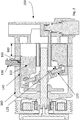
- Fig. 1 depicts a variable displacement compressor 100 in a reduced stroke length operation 170 for generating a signal indicating a stroke speed and a stroke length as described herein.
- the variable displacement compressor comprises a piston 110, a sensor probe 130, and a target 140.
- the compressor may further comprise a swash plate 120, a calibration target 150, and a housing 160.
- a processing unit (not shown) may be part of the sensor probe, part of the controller, or of the compressor or separate component.
- the processing unit may be implemented in a dedicated processing unit, or be a module of a general vehicle controller, such as compressor control unit or module and/or part of a Heating Ventilation and Air Conditioning (HVAC) system or the engine control unit.
- HVAC Heating Ventilation and Air Conditioning
- Fig. 2 depicts the variable displacement compressor 100 of Fig. 1 in an increased stroke length operation 180.
- the increased stroke length of the piston is a result of an increased swash plate angle 125.
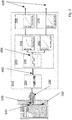
- Fig. 3 depicts a block diagram showing an overview of one embodiment of the invention.
- the resonance circuit 210 including the sensor coil 135 generates a signal including the presence and absence of a target 140 (and optionally a calibration target 150).
- the indication may be by means of a frequency change in the signal depending on if the target is present or absent.
- An FM demodulation 220 located in a demodulation circuit 230 may demodulate the resonance signal to generate a signal indicating the presence and absence of the target 140.
- a piston stroke length 240 and piston speed 250 may be calculated as described herein.
- the piston stroke length 240 may be succeeded by a linearization of piston stroke length 260.
- the piston speed 250 may be succeeded by a linearization of piston speed 270 prior to calculating a piston stroke length and a piston speed.
- the sensor probe (130) may comprise two coils, one transmitting coil and a receiving coil.
- the resonance circuit may in this case comprise both a transmitting and a receiving circuit.
- the signal received by the receiving coil is processed in this case, for example by comparing the phase shift between the transmitted and received signal.
- the speed and stroke sensor output signal (635) is preferably (but not limited to) a PWM, SENT, LIN, PSI5 or CAN output.
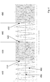
- Fig. 4 depicts a demodulated signal 450 and resonance signal 460.
- the demodulated signal 450 may be used to indicate the presence and the absence of a target.
- the demodulated signal 450 may be generated from an FM demodulation of a frequency, such as a frequency of the resonance signal 460, where the frequency of the resonance signal 460 may be sensitive to an impedance change of an eddy current sensor coil 135 resulting from an absence or a presence of a target.
- the first signal 450 may also be generated by other means, such as by decoding signals from the sensor probe 130.
- the impedance change may also be the result of a variation of an air gap between the sensor probe and the piston.
- the increased frequency shown in section 430 of Fig. 4 may be the result of reduced inductance in a resonance circuit due to an opposing magnetic field produced by eddy currents in the piston.
- the lower frequency section 440 may be due to increased inductance produced by a target, such as a gap in the piston.
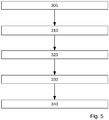
- Fig. 5 depicts steps for generating a signal indicating a stroke speed and a stroke length of a piston.
- the processing unit supplies the resonant frequency circuit and receives the resonant frequency signal 460 from the resonant circuit.
- the resonant frequency signal 460 may be demodulated to demodulated signal 450.
- the demodulated signal 450 indicates a presence 440 and/or an absence 430 of the target 140 as the target 140 moves relative to the sensor probe 130, the sensor probe 130 allowing first timestamps (such as raising edges) 410 to be measured at times when the target 140 moves from being present 440 at the sensor probe 130 to being absent 430 from the sensor probe 130, and the sensor probe 130 allowing second timestamps 420 (such as falling edges) to be measured at second times when the target 140 moves from being absent 430 from the sensor probe 130 to being present 440 at the sensor probe 130.
- first timestamps such as raising edges
- second timestamps 420 such as falling edges
- the steps further include a step to determine 320 a periodicity of the piston 110 by applying a first function to at least two timestamps of the first timestamps 410 or at least two timestamps of the second timestamps 420.
- the steps further include determining 330 a target duty cycle ratio by comparing a target pulse duration generated from at least one timestamp of the first timestamps 410 and at least one timestamp of the second timestamps 420 with the periodicity.
- the steps further include generating 340 the signal indicating the stroke speed and the stroke length from the periodicity and the target duty cycle ratio.
- Fig. 6 depicts the resonance frequency in the resonance circuit at different piston locations relative to top dead centre (TDC) 710 in a maximum stroke length operation.
- TDC top dead centre
- the resonance frequency is lower indicating presence of the target 140.
- the resonance frequency increases indicating the absence of the target 140.
- the resonant frequency drops again at 720 indicating the presence of the calibration target 150.
- BDC bottom dead centre
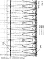
- Fig. 7 depicts a graph showing location of a piston from a top dead centre (TDC) as a function of time running at 3000 RPM.
- Solid line 510 shows a piston location as a function of time at low piston stroke length (ca 4 mm stroke length).
- Dotted line 520 shows piston location as a function of time at medium stroke length (ca 14 mm stroke length).
- Dashed line 530 shows piston location as a function of time at high stroke length (ca 28 mm stroke length). For all the shown stroke lengths, the piston speed (and so the compressor speed) is the same.
- Reference numeral 540 shows the locations of the piston where a sensor signal 450 indicates a presence 440 of a target.
- the sensor probe indicates the presence 440 of a target when the piston is located near the piston top dead centre.
- the sensor probe indicates the absence of the target when the piston is near the bottom dead centre.
- time during which the sensor signal indicates a presence 440 of a target decreases (and so the target duty cycle ratio) as the stroke length increases. By measuring the decrease in target duty cycle ratio, the stroke length of the target may be calculated with high accuracy and low latency as described herein.
- Fig. 7 also depicts locations 570 of the piston when the sensor probe indicates the presence of a calibration target 150.
- the location of piston when the sensor probe indicates the presence of a calibration target may be near the bottom dead centre (BDC) of the piston.
- the calibration target may be located at any suitable location, such as, but not limited to, within 1/3 from the piston bottom dead centre at maximum stroke length.
- the location of piston when the sensor probe indicates the presence of a calibration target may also determine a calibration duty cycle ratio and further used to improve the accuracy of the calculation of piston stroke lengths as described herein.
- Fig. 8 depicts a graph showing location of a piston from the top dead centre as a function of time running at 6000 RPM. As can be seen in the figure, the duty cycle ratio and the corresponding calculation of the piston stroke length is unaffected by the change in compressor speed.
- the piston location as a function of time is depicted as substantially sinusoidal in Fig. 7 and 8 .
- the actual location of the piston may not be approximately sinusoidal as long as the duty cycle ratio of the target time can be mapped to stroke length.
- the mapping may be analytically and/or experimentally.
- the mapping may also be analytical with correction factors derived experimentally.
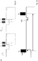
- Fig. 9 depicts an ideal position S 0 , S 1 (case a) and a shifted sensor position S 0 ', S 1 ' to (case b).
- the sensor position may be shifted due to tolerance.
- Tolerances in piston movement direction (x-direction) between the target groove and the sensor location affects the accuracy of the calculation of stroke length from duty cycle ratio. Tolerances can be caused by manufacturing of sensor parts, assembly of sensor, assembly of sensor to compressor, position tolerances of compressor mounting hole, etc.
- Case a) shows an example where the piston moves from s0 to s1, i.e. a minimum stroke length in this configuration of for example 0,7mm. Case a) depicts an ideal position. In this case, the resulting duty cycle ratio is about 50%.
- a calibration routine is therefore described that can be applied without any costly reference piston stroke sensor, i.e. by using a second target on the piston, a calibration target.
- the target may be a second groove, such as an oil groove already located on the piston without any further need of piston modification.
- Fig. 10 depicts a minimum stroke length for the sensor probe to detect the calibration target.
- the piston stroke needs to be large enough to enable the sensor probe to detect the first edge of the calibration groove 150, e.g. travelling from top dead centre S 0 to calibration target detection S 2 .
- the calibration can be done at any time when the piston stroke is large enough for the sensor probe to indicate the calibration target. Suitable times for performing the calibration may include, during the compressor end-of-line test or during the vehicle end-of-line test. The calibration may also be performed during vehicle operation, such as with certain intervals, or at vehicle or compressor start-up.
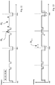
- Fig. 11 shows resonant frequency as a function of time during two revolutions of the swashplate rotating at 3000 RPM.
- Fig. 11 also shows the time between two calibration frequency drops ( ⁇ t 1 ) and time between a main target frequency drop and a calibration frequency drop ( ⁇ t 2 ).
- this information can be used to distinguish the drop indicating the calibration target from the main target.
- the signal will indicate four drops per rotation. Since it is known that time between two calibration frequency drops ( ⁇ t 1 ) is shorter than time between a main target frequency drop and a calibration frequency drop ( ⁇ t 2 ), this can be used to distinguish the main target drop from the calibration target drop.
- the identification of the main target drop from the calibration drop can also be done e.g. by identifying that the groove depth of the calibration groove (and so the frequency drop) is smaller than the depth of the sensor groove.
- the frequency drop may be the result of a different shape or material of the calibration target. The difference in frequency drop is detectable to identify if the frequency drop is from the main target or from the calibration target.
- Fig. 12 shows the same configuration as Fig. 11 where tolerance has introduced an error in the form of a time shift ( ⁇ t error ) as described under Fig. 9 in relation to case b).
- the described case b) in Fig. 9 results in the correct frequency signal (solid line, Fig. 12 ) being modified to a tolerance affected frequency signal (dotted line) and results in an incorrect target duty cycle ratio being calculated.
- the signal indicating the calibration target may be used to calculate a calibration duty cycle ratio.
- the calibration duty cycle ratio may be independent of axial tolerances (the time difference between the rising edge of the sensor groove (t1) and the falling edge of the calibration groove (t2) is independent from axial tolerances).
- the calibration duty cycle ratio is independent of tolerances in piston movement direction.
- the calibration duty cycle ratio is also independent of the compressor RPM.
- the correct target duty cycle ratio for one or more given calibration duty cycle ratio is predetermined.
- the relationship can be stored as an algorithm or a look-up table and be calculated from piston geometry or measured with a reference stroke sensor, automatically stored and may be used for all compressors of the same type. Using one or more known correlations between calibration duty cycle ratio and target duty cycle ratio, one or more point calibrations can be performed.
- a one-point calibration can be done by applying a correcting factor to the target duty cycle ratio (such as calibrating the complete look-up-table and/or map) in order to adjust the calculations to the correct output value of 70%.
- the one point calibration can alternatively be done after linearization of the sensor output.
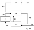
- Fig. 13 depicts a system for regulating a cooling (or heating) capacity of a variable displacement compressor.
- the system may comprise a compressor 605, a signal processing unit 610, a compressor controller 615, and a Heating, Ventilation, and air conditioning unit (HVAC unit) 620.
- the system may further involve a sensor signal 630, a speed and stroke signal 635, additional sensor signals 640 like the pressure in the suction part of the compressor or the pressure in the crank case of the compressor, a swash plate angle adjustment signal 650, a compressor control signal 660, and a HVAC input signal 670.
- the compressor 605 may be driven by compressor rotor angular velocity 680.
- the compressor controller 615 may receive a compressor control signal 660 with a requested compressor performance (such as a requested piston stroke length, a requested swash plate angle, a requested refrigerant mass flow, a requested suction pressure and/or a requested evaporator outlet air temperature, and/or a requested compressor torque).
- a requested compressor performance such as a requested piston stroke length, a requested swash plate angle, a requested refrigerant mass flow, a requested suction pressure and/or a requested evaporator outlet air temperature, and/or a requested compressor torque.
- the controller reads speed and stroke signal 635 from signal processing unit 610, in which the piston stroke length and speed is calculated or derived based on sensor signal 630 with high accuracy and low latency as described above.
- the compressor controller 615 may affect the swash plate angle adjustment signal 650 to increase or decrease the swash plate angle to reach the requested compressor performance.
- the swash plate angle adjustment signal 650 is affected until the read piston stroke length corresponds to the requested piston stroke length. Where the external control signal 670 indicates desired swash plate angle the desired swash plate angle may be converted to corresponding piston stroke length (or piston stroke length signal is converted to swash plate angle) before the actual and desired values are compared.
- the compressor controller 615 may use additional sensor signals 640, to generate appropriate swash plate angle adjustment signal 650.
- the compressor controller may read additional sensor signals 640, such as including compressor and/or refrigeration cycle suction pressure and crankcase pressure, and compressor speed.
- the adjustments to the current compressor mass flow rate may be calculated from the piston speed, the piston stroke length, and/or additional sensor signals 640 such as suction and/or evaporator pressure signals.
- the HVAC unit 620 may receive a HVAC input signal 670 (such as indicating current suction pressure, evaporator outlet air temperature, compressor torque, compressor speed, and/or vehicle compartment air temperature) to generate compressor control signal 660.
- the signal values may be directly measured or calculated and/or estimated from signal values.
- the HVAC may be a separate processing unit (such as a HVAC ECU) or be part of an engine processing unit (such as an engine ECU) or part of other vehicle processor units.
- the compressor controller 615 may be located, with the HVAC unit 620, be a module of the HVAC unit 620, or be located in any other suitable location.
- the compressor controller 615 may physically be part of the compressor 605, or separate but operationally connected to the compressor.
- the signal processing unit 610 may be located on the compressor 605, with the compressor controller 615 (such as integrated in the compressor controller 615), be a module of the compressor controller 615 or be separate but operationally connected to the compressor and/or compressor controller 615 and/or HVAC unit 620.
- the signal processing unit 610 may be part of the sensor housing (such as integrated in the sensor housing). The processing unit may also be integrated into the HVAC unit.
Landscapes
- Engineering & Computer Science (AREA)
- Mechanical Engineering (AREA)
- General Engineering & Computer Science (AREA)
- Computer Hardware Design (AREA)
- Measurement Of Length, Angles, Or The Like Using Electric Or Magnetic Means (AREA)
- Compressors, Vaccum Pumps And Other Relevant Systems (AREA)
Abstract
Description
- The present application is directed to an improved variable displacement reciprocating piston unit generating a signal indicating current piston stroke speed and piston stroke length with low latency.
- In the following, the variable displacement reciprocating piston unit will be described in the context of a variable displacement compressor. However, this is only an example to give context to the invention. It is obvious to the skilled person that the invention may be applied for any variable displacement reciprocation piston unit, machine and/or aggregate, such as a variable displacement compressor or pump.
- US patent publication
US 6,991,435 B2 relates to a variable displacement compressor including a processing unit estimating an inclination angle of a swash plate based on an output signal of a sensor. - It is an aim of the present invention to improve efficiency, reduce fuel consumption, and reduce exhaust emission in vehicle operations. A further aim of the invention includes improved safety of vehicle air conditioning operation and improve operation reliability of air conditioning compressors. A further objective is to improve the accuracy and reduce the latency of compressor torque calculations. A further aim is to provide additional monitoring capabilities of compressor operations. A further aim is to improve the accuracy and reduce the delay of compressor piston stroke length feedback and an additional, improved feedback of compressor piston reciprocation frequency.
- The objectives of the present invention are solved by the subject-matter of
claim 1. - In particular the objectives are solved by a variable displacement reciprocating piston unit, such as a compressor or pump, for generating a signal indicating a piston stroke speed (reciprocation frequency) and a piston stroke length, the variable displacement reciprocating piston unit comprising at least one processing unit, at least one sensor probe, at least one target, the piston having a top dead centre (TDC) and a bottom dead centre (BDC), and the at least one processing unit configured to receive a signal from the sensor probe, the sensor probe indicating a presence and/or an absence of the target as the target moves relative to the sensor probe, the signal allowing first timestamps to be measured at times when the target moves from being present at the sensor probe to being absent from the sensor probe (the time may be measured at an edge or a flank of the signal), and the signal allowing second timestamps to be measured at second times when the target moves from being absent from the sensor probe to being present at the sensor probe; determine a periodicity by applying a first function to at least two timestamps of the first timestamps or at least two timestamps of the second timestamps (i.e. between two edges and/or two flanks); the periodicity may be related to the time period or reciprocation frequency of the piston. The first timestamps may correspond to raising edges of the signal and the second timestamps may correspond to falling edges (flanks) of the signal. The first timestamp may also correspond to falling edges (flanks) of the signal and the second timestamps may correspond to raising edges of the signal, determine a target duty cycle ratio by comparing a target pulse duration generated from at least one timestamp of the first timestamps and at least one timestamp of the second timestamps with the time period; and generate the signals indicating the stroke speed (or stroke frequency) and the stroke length from the time period and the target duty cycle ratio, wherein the sensor probe, the target, and the piston are located in relation to each other, so that the target is moved from being absent from the sensor probe to being present at the sensor probe when the piston travels towards the top dead centre (TDC) position, and so that the target is moved from being present at the sensor probe to being absent from the sensor probe when the piston travels towards the bottom dead centre (BDC) position.
- Advantages of the invention includes faster and significantly more accurate piston movement feedback. The faster and more accurate piston movement feedback improves vehicle efficiency and reduces fuel consumption and exhaust emission by increasing the speed of swash plate angle control, in particular by enabling a new type of compressor control. Swash plate angle and hence piston stroke length is typically controlled by regulating a pressure difference in the compressor. Previous compressor designs include a "bleed hole". The bleed hole results in compressed refrigerant bleeding back from the crank case chamber of the compressor to the suction chamber, increasing energy consumption and temperature. The invention allows the bleed hole to be reduced or closed. Closing or reducing the bleed hole results in more severe requirements for the swash plate control. Without bleed hole it is crucial to react very fast on swash plate movements. The less stable swash plate can be stabilized in a control loop using the signal of the present invention, especially the piston stroke length that can directly be calculated or derived from the signal leading to a more precise control.
- The invention further allows to improve the compressor control using the piston speed or the compressor speed, respectively, that can directly be calculated from the sensor signal, in order to react very fast on any compressor speed changes.
- The invention further allows the mass flow rate of the compressor to be directly calculated from the direct piston speed and stroke length calculation in addition with signals, such as signals from suction chamber pressure sensors.
- The invention may also be used to calculate additional physical values in addition to piston stroke speed and piston stroke length. These may include displacement rate, clearance volumetric efficiency, work of the compressor, coefficient of friction (piston to cylinder), refrigerant mass flow, etc. These calculations may require additional sensor information.
- For highest precision of mass flow calculation, values indicating discharge pressure, suction temperature and discharge temperature figures may also be included, in addition to piston speed, piston stroke and suction pressure. With more sensor values input, the accuracy of the mass flow calculation further increases.
- A desired mass flow rate of the compressor can hence be achieved by adjusting the swash plate angle until the desired mass flow rate is achieved. It is also possible to derive a faster and more accurate calculation of the actual compressor torque using the current invention. The faster and more accurate actual compressor torque calculation can be fed to engine control unit for more efficient and smoother vehicle operations.
- The invention allows the safety of vehicle air conditioning operation and the operation reliability of air conditioning compressors to be improved by allowing additional and direct monitoring of the compressor operations. Appropriate actions (such as indicating a warning signal to the user and/or decreasing compressor load and/or turning off the compressor) can be taken if the speed and/or load of the compressor is overreached. The additional signal of piston stroke speed may be compared with independent signals of engine speed and/or compressor rotor angular velocity to directly monitor compressor failure, such as compressor lock up, compressor or liquid slugging (liquid compression in cylinder bore). A slippage of the belt can be detected with the invention.
- The invention also allows to measure precisely the material thickness of e.g. the piston skirt and thus enables the early detection of piston wear which increases the operation reliability of the air conditioning compressor.
- The more accurate and faster piston data allows faster feedback to the air conditioning control allowing a more precise air conditioning control, further reducing energy consumption and improving passenger comfort, for examples in case when a high peaking torque is measured. In this case the invention allows the compressor torque to be reduced.
- One feature contributing to the objectives of the invention is a sensor probe and a target allowing the processing unit to measure timestamps during which the piston is located in a part of the stroke with pre-determined distance. By extracting the timestamps when the edge of the target moves past the sensor probe, both piston speed, and piston stroke length can be derived.
- The periodicity of the piston may be derived from a time difference at least two timestamps of the first timestamps (time difference between two "falling" flanks) or at least two timestamps of the second timestamps (time difference between two "raising" edges). The periodicity may also be derived from measuring every n-th timestamps of the first and/or the second timestamps, such as every third timestamp. The time difference is then suitably divided by the number of interval number to arrive at the periodicity during the measured time interval. The periodicity is preferably expressed in time units, but may also be expressed in one over time unit (frequency) with corresponding amendments of computations.
- In this way, the periodicity (i.e. the piston/swash plate/compressor reciprocation /revolution time) may be calculated from the time difference between a first rising edge and a second raising edge or a first falling edge and a second falling edge of the signal indicating the presence and absence of the target.
- The target duty cycle ratio may be derived by comparing, preferably dividing a target pulse duration with the periodicity, the target pulse duration typically derived by measuring the time between one or more timestamps of the first timestamps and one or more timestamps of the second timestamps (time between "rising" to "falling" or time between "falling" to "raising"). By dividing the pulse duration with the periodicity, a stroke speed independent target duty cycle ratio can be derived.
- The target duty cycle ratio corresponds to the amount of time where the target is present at the sensor probe over to the time of a full piston stroke. Since the time where the target is present at the sensor probe added to the time where the target is absent at the sensor probe equals the time of a full stroke, the target duty cycle ratio may also be defined as the time where the target is not present at the sensor probe over to the time of a full piston stroke, with the corresponding adjustments to calculations.
- The piston stroke reciprocation time may be indicated as frequency.

- Where Trec is the piston reciprocation time, and frec is the piston stroke reciprocation frequency.
- The piston stroke length may be indicated as target duty cycle ratio or may be derived from the target duty cycle ratio by transformation of duty cycle ratio to stroke length.
- The piston stroke length may be adjusted for piston movements that are not sinusoidal (for all stroke lengths, or for some stroke lengths, such as for longer stroke lengths). The piston stroke length may also be adjusted for a specific swash plate piston connection design and hysteresis in piston movements.
- In one embodiment, the target is indicated by a change of current carrying capacity and/or change by a piston topography in the target location and the change of current carrying capacity may be the result of the change of topography; and the change of topography preferably may be one or more of an air gap in the piston, a recess in the piston, a groove on the piston, a slope or edge of the piston, or a hole in or of the piston. The change of current carrying capacity may be a result of a specific material in a target area of the piston. The specific material may copper, aluminium and/or hard potting or any other suitable material. The sensor probe is further preferably attached to a housing of the compressor. The advantages include a design that reduces the cost of manufacturing.
- In one embodiment, the target area has a convex topography, is bow shaped, and/or is designed in an arched manner and/or the topography of the target area compensates for axial rotation movement of the piston, and/or an air gap between the sensor probe and the target is substantially independent of some piston axial rotation, such as small piston axial rotation, such as piston axial rotation within ±3° of an un-rotated and/or initial piston position.
- The rotation may be a slight initial rotational misplacement of the piston, rotation variations during operation, and/or an axial rotational drift over time or any other axial rotation movement of the piston.
- The further advantage of this embodiment is that air gap between the sensor probe and the target is less dependent on (or substantially independent of) some or all piston axial rotation movements which may allow for variations in piston axial rotational without substantially affecting the sensor signal received from the sensor probe. A further advantage of this embodiment may be increased robustness of piston stroke speed and stroke length indications, and/or increased tolerance during parts manufacturing and/or assembly.
- It is also possible to use the piston without modification. For example, the slope near the edge of the piston can be used, or the edge itself or other piston geometry. The end of the piston skirt and/or the bottom of the piston may be used as target. The sensor probe position might have to be adapted in this case. The sensor probe is preferably located so that it is over or close to the target in a top dead centre piston position, and not over the target in a bottom dead centre piston position.
- In one embodiment, a sensor may comprise the sensor probe and the processing unit. The sensor may be an eddy current sensor. The signal indicating the presence and absence of the target may be directly measured, such as by measuring the impedance of the sensor coil or the current, or voltage or frequency value of the signal, or may be derived/generated from a demodulation of a resonance frequency in a resonant circuit, or by measuring a phase shift between a transmitted signal and a received signal that is influenced/affected by the induced eddy currents.
- The sensor may also be a Hall effect sensor. A Hall effect sensor may be biased with a magnet, or the target may be ferromagnetic in order to determine the presence and the absence of the target from the sensor probe.
- Advantages of the sensor being an eddy current sensor includes contact-less proximity measurement substantially insensitive to (non-electrically conducting) materials in a gap between the sensor and the target. Advantages of relying on frequency modulation includes improved temperature independence of target detection. In order to improve the accuracy of the measurements, digital and/or analogue filters may be applied to the signal. The target may be a location on the piston and increasing and/or inhibiting eddy current compared to other parts of the piston allowing the presence/absence of the target to be sensed.
- Any piston topology can be used that results in an air gap and/or material thickness and/or material variety change between sensor probe and piston while the piston is moving to indicate the presence and absence of a target.
- For using an eddy current sensor, not only the air gap is important, but also the material thickness, depending on the penetration depth of the electro-magnetic field in the piston material. For example, a thin piston shell can be detected with the current samples, and any sufficient material thickness change can be used as trigger for target. The electrical conductivity of the piston may also be changed locally in order to reduce the eddy current intensity or to prevent the eddy currents from flowing. Adding a groove or changing the thickness of the piston changes the current carrying capacity and may be used as a target and indicated by an eddy current sensor. Using a groove as a local eddy current obstruction results in significant sensitivity of the sensor probe, but also weakens the mechanical stability of the piston.
- The groove may be filled with a material of less or higher electrical conductivity compared to the non-target part of the piston. Where the piston is made of aluminium, the target may be copper or "hard" potting. Any combination of material or different current carrying capacity may be used.
- In order to prevent the eddy currents from flowing, small grooves or holes may be formed in the piston, such as by machine defined small grooves or drilling small holes into the target area of the piston. By machining lines or drilling small holes in the piston, the mechanical strength of piston significantly improved compared to piston with one large groove. Any modification on the piston target area can be used, that changes the eddy current intensity compared to the rest of the piston.
- In one embodiment, the sensor probe comprises one or more sensor coils preferably at least one flat wound coil on a bobbin and/or at least one flat coil on a PCB in one or more layers. The advantages include a good trade-off between accuracy and manufacturing costs.
- In one embodiment, the sensor coil has a transmitting coil and a receiving coil that are either wounded coils or preferably PCBs coils on different layers and the sensor signal is induced in the receiving coil and either a voltage, current, frequency, or phase shift is processed in order to create the processed signal.
- In one embodiment the sensor probe is located so that the sensor probe is indicating the presence of the target near the top dead centre (TDC) position and the sensor probe is preferably at the same time located so that sensor probe is indicating the absence of the target in bottom dead centre (BDC) position.
- The location allows a target duty cycle ratio to be derived regardless of piston stroke length, and hence allows a calculation of the stroke length from the duty cycle ratio, in all stroke length operations.
- The calculation of stroke length may be independent of piston (and compressor) speed.
- In one embodiment, the stroke length is derived from the target duty cycle ratio using a map that translates and/or linearizes from target duty cycle ratio to stroke length. The map preferably includes one or more functional relationships, such as a relationship including one or more polynomial function, one or more trigonometric functions, or one or more look-up tables. The functional relationship may be stored in one or more look-up tables.
- The piston stroke length may be derived by interpolation between target duty cycle ratio values (such as two or more consecutive target duty cycle ratio values) in order to calculate a corresponding piston stroke length. The target duty cycle ratio values may be retrieved from a look-up table. The interpolation may be of an order (such as an n-order), such as a first order, preferably second order, or more preferably third order.
- In one embodiment, the variable displacement reciprocation piston unit, preferably the piston, comprises a calibration target, preferably different from the target, and preferably in line with the target. The sensor probe may indicate a presence and an absence of the calibration target as the piston (and the calibration target) moves past the sensor probe to preferably generate a calibration duty cycle ratio.
- The problem addressed includes that tolerance in piston movement direction (x-direction) between the target and the sensor probe location have impact on the accuracy of piston stroke length from duty cycle ratio calculation.
- The processing unit may further be configured to calibrate the stroke length generated from the target duty cycle ratio using the signal indicating the presence of the calibration target.
- The calibration may include applying a calibration factor to the map that translates from target duty cycle ratio to stroke length.
- The improvement allows production variations and/or usage affects to the piston stroke to be eliminated or reduced. The improvement also allows the manufacturing costs to be reduced by reducing the tolerance requirements on manufacturing, in turn leading to cheaper production. This further improves the accuracy of the indication of the piston stroke length detection, in particular over time, as the detection can be calibrated automatically and during run-time. Further, for design reasons, the calculation of stroke length is more sensitive to duty cycle ratio changes in the lower region. The embodiment may be used to increase the accuracy in high stroke lengths regions.
- In one embodiment, the step of calibrating the generated stroke length includes generating a calibration duty cycle ratio from a calibration timestamp measured when the calibration target moves from being absent the sensor probe to being present the sensor probe (falling edge) and/or when the calibration target moves from being present the sensor probe to being absent the sensor probe (raising edge). The calibration timestamp may be compared with the first and/or second timestamp to derive a calibration duty cycle ratio, preferably using the relationship:

- In one embodiment, the step of calibrating the generated stroke length includes correcting the target duty cycle ratio with a correcting factor of a correction function, the correcting factor or function derived from the current calibration duty cycle ratio and the current target duty cycle ratio, and a pre-stored accurate correlation between calibration duty cycle ratio and target duty cycle ratio. The correcting factor may be applied to the map translating from target duty cycle ratio to stroke length.
- In one embodiment, the step of calibrating the generated stroke length is performed when the piston stroke length is above a minimum stroke length required for the sensor probe to indicate the presence of the calibration target, such as during compressor and/or vehicle end-of-line test or during normal operations, such as with a certain time interval, at vehicle start-up, or continuous when the stroke length is above a minimum calibration stroke length.
- In one embodiment, the minimum stroke length required for the sensor probe to indicate the presence of the calibration target may be 2/3 of the maximum stroke length depending on the position of the sensor probe and the calibration target.
- In one embodiment, the calibration target is indicated by a change of current carrying capacity and/or change by a piston topography in the target location and the change of current carrying capacity may be the result of the change of topography. The change of topography may include: an air gap in the piston, a recess in the piston, a hole in or of the piston, a groove on the piston, a slope or edge of the piston. An oil groove located on the piston skirt may be used as calibration target. The improvement allows an eddy current sensor to be used to indicate the presence and absence of the target. By using the oil groove as a calibration target, no further adjustments are made to the piston, thereby avoiding any further piston machining.
- In one embodiment, the signal indicating the presence of the calibration target is distinguishable from the signal presence of the main target although the same sensor probe is used. The signals may be distinguishable using uncalibrated piston stroke information, such as piston speed and/or piston stroke length and/or difference in calibration and target presence duration.
- That is, if the maximum possible error of an uncalibrated sensor is known, the different grooves can be identified by their position on the piston by the uncalibrated default piston stroke information. For example, if the maximum error is e.g. ±5mm, a frequency change at a piston position above e.g. 15mm must belong to a calibration target.
- The distinction may also be based on a difference in time between two calibration target frequency changes (drops) compared to a time difference between a main target frequency drop and a calibration frequency drop.
- The difference may also be based on a difference in frequency change (drop) between the target and the calibration target. The difference may be due to a difference in topography and/or material leading to a different induced eddy current as the target and the calibration target moves relative to the sensor probe.
- The differentiation between the main groove and the calibration groove ensures that the normal operation mode is not influenced by the calibration groove.
- In one embodiment, the step generating the signal indicating the stroke speed and the stroke length includes a linearization of the target duty cycle ratio. In order to improve the linearization accuracy, the target duty cycle ratio may be given by the equation:

- The equation may correspond to a comparison between detection of pulse width ON time (420 till 410) and the pulse width OFF time (410 till 420) where pulse width ON_time is a time duration where the sensor probe (130) is indicating the presence of the target, and the OFF_time is a time duration where the sensor probe (130) is indicating the absence of the target and Period is the total ON_time and OFF_time period. The equation allows better linearity and therefore better fit function adoption.
- In the following, embodiments of the invention are described with respect to the figures, wherein
-
Fig. 1 shows a variable displacement compressor according to one embodiment of the invention in a short stroke length operation. -
Fig. 2 shows a variable displacement compressor according to one embodiment of the invention in a long stroke length operation. -
Fig. 3 is a block diagram showing a sensor probe, a processing unit, and signal output. -
Fig. 4 shows schematically a signal allowing the absence and the presence of a target to be extracted from a frequency demodulation of a resonance signal. -
Fig. 5 shows steps of a method for generating a signal according to one embodiment of the invention. -
Fig. 6 shows a resonance frequency signal as a function of a piston distance from a top dead centre (TDC). -
Fig. 7 shows a graph depicting piston movement in three different stroke length operation. -
Fig. 8 shows the same information asFig. 7 with increased piston speed. -
Fig. 9 shows an ideal position and a position of a sensor coil shifted due to tolerance. -
Fig. 10 shows a minimum stroke length for the sensor probe to detect the calibration target. -
Fig. 11 shows resonant frequency as a function of time during two revolutions of the swashplate at 3000 RPM. -
Fig. 12 shows the same configuration asFig. 11 where tolerance has introduced an error in the form of a time shift. -
Fig. 13 shows an exemplary system for controlling the temperature in a car according to one embodiment of the invention. -
Fig. 1 depicts avariable displacement compressor 100 in a reducedstroke length operation 170 for generating a signal indicating a stroke speed and a stroke length as described herein. The variable displacement compressor comprises apiston 110, asensor probe 130, and atarget 140. The compressor may further comprise aswash plate 120, acalibration target 150, and ahousing 160. A processing unit (not shown) may be part of the sensor probe, part of the controller, or of the compressor or separate component. The processing unit may be implemented in a dedicated processing unit, or be a module of a general vehicle controller, such as compressor control unit or module and/or part of a Heating Ventilation and Air Conditioning (HVAC) system or the engine control unit. -
Fig. 2 depicts thevariable displacement compressor 100 ofFig. 1 in an increasedstroke length operation 180. The increased stroke length of the piston is a result of an increasedswash plate angle 125. -
Fig. 3 depicts a block diagram showing an overview of one embodiment of the invention. Theresonance circuit 210 including thesensor coil 135 generates a signal including the presence and absence of a target 140 (and optionally a calibration target 150). The indication may be by means of a frequency change in the signal depending on if the target is present or absent. AnFM demodulation 220 located in ademodulation circuit 230 may demodulate the resonance signal to generate a signal indicating the presence and absence of thetarget 140. From the absence and presence of thetarget 140, apiston stroke length 240 andpiston speed 250 may be calculated as described herein. Thepiston stroke length 240 may be succeeded by a linearization ofpiston stroke length 260. Thepiston speed 250 may be succeeded by a linearization ofpiston speed 270 prior to calculating a piston stroke length and a piston speed. - The sensor probe (130) may comprise two coils, one transmitting coil and a receiving coil. The resonance circuit may in this case comprise both a transmitting and a receiving circuit. The signal received by the receiving coil is processed in this case, for example by comparing the phase shift between the transmitted and received signal.
- The speed and stroke sensor output signal (635) is preferably (but not limited to) a PWM, SENT, LIN, PSI5 or CAN output.
-
Fig. 4 depicts ademodulated signal 450 andresonance signal 460. Thedemodulated signal 450 may be used to indicate the presence and the absence of a target. Where the sensor is an eddy current sensor, thedemodulated signal 450 may be generated from an FM demodulation of a frequency, such as a frequency of theresonance signal 460, where the frequency of theresonance signal 460 may be sensitive to an impedance change of an eddycurrent sensor coil 135 resulting from an absence or a presence of a target. Thefirst signal 450 may also be generated by other means, such as by decoding signals from thesensor probe 130. The impedance change may also be the result of a variation of an air gap between the sensor probe and the piston. - The increased frequency shown in
section 430 ofFig. 4 may be the result of reduced inductance in a resonance circuit due to an opposing magnetic field produced by eddy currents in the piston. Thelower frequency section 440 may be due to increased inductance produced by a target, such as a gap in the piston. -
Fig. 5 depicts steps for generating a signal indicating a stroke speed and a stroke length of a piston. The processing unit supplies the resonant frequency circuit and receives theresonant frequency signal 460 from the resonant circuit. Inoptional step 305, theresonant frequency signal 460 may be demodulated todemodulated signal 450. - In
step 310, thedemodulated signal 450 indicates apresence 440 and/or anabsence 430 of thetarget 140 as thetarget 140 moves relative to thesensor probe 130, thesensor probe 130 allowing first timestamps (such as raising edges) 410 to be measured at times when thetarget 140 moves from being present 440 at thesensor probe 130 to being absent 430 from thesensor probe 130, and thesensor probe 130 allowing second timestamps 420 (such as falling edges) to be measured at second times when thetarget 140 moves from being absent 430 from thesensor probe 130 to being present 440 at thesensor probe 130. The steps further include a step to determine 320 a periodicity of thepiston 110 by applying a first function to at least two timestamps of thefirst timestamps 410 or at least two timestamps of thesecond timestamps 420. The steps further include determining 330 a target duty cycle ratio by comparing a target pulse duration generated from at least one timestamp of thefirst timestamps 410 and at least one timestamp of thesecond timestamps 420 with the periodicity. The steps further include generating 340 the signal indicating the stroke speed and the stroke length from the periodicity and the target duty cycle ratio. -
Fig. 6 depicts the resonance frequency in the resonance circuit at different piston locations relative to top dead centre (TDC) 710 in a maximum stroke length operation. Close to TDC, the resonance frequency is lower indicating presence of thetarget 140. Above the TDC, the resonance frequency increases indicating the absence of thetarget 140. At a certain distance from TDC, the resonant frequency drops again at 720 indicating the presence of thecalibration target 150. As the piston (and the calibration target) moves past the sensor probe, the resonant frequency increases again, indicating the absence of the calibration (and main) target. The piston reaches finally bottom dead centre (BDC) 730 (which is the maximum stroke length for this configuration). -
Fig. 7 depicts a graph showing location of a piston from a top dead centre (TDC) as a function of time running at 3000 RPM.Solid line 510 shows a piston location as a function of time at low piston stroke length (ca 4 mm stroke length).Dotted line 520 shows piston location as a function of time at medium stroke length (ca 14 mm stroke length). Dashedline 530 shows piston location as a function of time at high stroke length (ca 28 mm stroke length). For all the shown stroke lengths, the piston speed (and so the compressor speed) is the same.Reference numeral 540 shows the locations of the piston where asensor signal 450 indicates apresence 440 of a target. As can be seen from the graph, in this example, the sensor probe indicates thepresence 440 of a target when the piston is located near the piston top dead centre. The sensor probe indicates the absence of the target when the piston is near the bottom dead centre. As can be seen from the graph, time during which the sensor signal indicates apresence 440 of a target decreases (and so the target duty cycle ratio) as the stroke length increases. By measuring the decrease in target duty cycle ratio, the stroke length of the target may be calculated with high accuracy and low latency as described herein. -
Fig. 7 also depictslocations 570 of the piston when the sensor probe indicates the presence of acalibration target 150. The location of piston when the sensor probe indicates the presence of a calibration target may be near the bottom dead centre (BDC) of the piston. The calibration target may be located at any suitable location, such as, but not limited to, within 1/3 from the piston bottom dead centre at maximum stroke length. The location of piston when the sensor probe indicates the presence of a calibration target may also determine a calibration duty cycle ratio and further used to improve the accuracy of the calculation of piston stroke lengths as described herein. -
Fig. 8 depicts a graph showing location of a piston from the top dead centre as a function of time running at 6000 RPM. As can be seen in the figure, the duty cycle ratio and the corresponding calculation of the piston stroke length is unaffected by the change in compressor speed. - The piston location as a function of time is depicted as substantially sinusoidal in
Fig. 7 and8 . The actual location of the piston may not be approximately sinusoidal as long as the duty cycle ratio of the target time can be mapped to stroke length. The mapping may be analytically and/or experimentally. The mapping may also be analytical with correction factors derived experimentally. -
Fig. 9 depicts an ideal position S0, S1 (case a) and a shifted sensor position S0', S1' to (case b). The sensor position may be shifted due to tolerance. Tolerances in piston movement direction (x-direction) between the target groove and the sensor location affects the accuracy of the calculation of stroke length from duty cycle ratio. Tolerances can be caused by manufacturing of sensor parts, assembly of sensor, assembly of sensor to compressor, position tolerances of compressor mounting hole, etc. - Case a) shows an example where the piston moves from s0 to s1, i.e. a minimum stroke length in this configuration of for example 0,7mm. Case a) depicts an ideal position. In this case, the resulting duty cycle ratio is about 50%.
- In case b) the position of centre of sensor coil in relation to the main groove has shifted due to tolerances. This results to a resulting duty cycle ratio that is much lower, about 20% in the example. If the incorrect (shifted) duty cycle ratio of 20% is used to calculate the stroke length, an incorrect stroke length would be the result.
- A calibration routine is therefore described that can be applied without any costly reference piston stroke sensor, i.e. by using a second target on the piston, a calibration target. The target may be a second groove, such as an oil groove already located on the piston without any further need of piston modification.
-
Fig. 10 depicts a minimum stroke length for the sensor probe to detect the calibration target. The piston stroke needs to be large enough to enable the sensor probe to detect the first edge of thecalibration groove 150, e.g. travelling from top dead centre S0 to calibration target detection S2. - As shown in
Fig. 10 , the calibration can be done at any time when the piston stroke is large enough for the sensor probe to indicate the calibration target. Suitable times for performing the calibration may include, during the compressor end-of-line test or during the vehicle end-of-line test. The calibration may also be performed during vehicle operation, such as with certain intervals, or at vehicle or compressor start-up. -
Fig. 11 shows resonant frequency as a function of time during two revolutions of the swashplate rotating at 3000 RPM.Fig. 11 also shows the time between two calibration frequency drops (Δt1) and time between a main target frequency drop and a calibration frequency drop (Δt2). - If for example, it is known that calibration is performed at maximum stroke length, this information can be used to distinguish the drop indicating the calibration target from the main target. The signal will indicate four drops per rotation. Since it is known that time between two calibration frequency drops (Δt1) is shorter than time between a main target frequency drop and a calibration frequency drop (Δt2), this can be used to distinguish the main target drop from the calibration target drop.
- The identification of the main target drop from the calibration drop can also be done e.g. by identifying that the groove depth of the calibration groove (and so the frequency drop) is smaller than the depth of the sensor groove. The frequency drop may be the result of a different shape or material of the calibration target. The difference in frequency drop is detectable to identify if the frequency drop is from the main target or from the calibration target.
-
Fig. 12 shows the same configuration asFig. 11 where tolerance has introduced an error in the form of a time shift (Δterror) as described underFig. 9 in relation to case b). The described case b) inFig. 9 results in the correct frequency signal (solid line,Fig. 12 ) being modified to a tolerance affected frequency signal (dotted line) and results in an incorrect target duty cycle ratio being calculated. - The stroke reciprocation time (T=t4-t1) does not change, but the pulsewidth time (ON time) decreases (t3-t1) leading to an incorrect duty cycle ratio and therefore an incorrect stroke length calculation.
- The tolerance affected target duty cycle ratio may be calculated as follows:

- The signal indicating the calibration target may be used to calculate a calibration duty cycle ratio. The calibration duty cycle ratio may be independent of axial tolerances (the time difference between the rising edge of the sensor groove (t1) and the falling edge of the calibration groove (t2) is independent from axial tolerances). The calibration duty cycle ratio may be defined:

- The correct target duty cycle ratio for one or more given calibration duty cycle ratio is predetermined. The relationship can be stored as an algorithm or a look-up table and be calculated from piston geometry or measured with a reference stroke sensor, automatically stored and may be used for all compressors of the same type. Using one or more known correlations between calibration duty cycle ratio and target duty cycle ratio, one or more point calibrations can be performed.
- From a (one-time) reference measurement it is known that a calibration duty cycle ratio of 75% corresponds to 26mm piston stroke length and that at this stroke, the target duty cycle ratio should be 70%.
- But, due to axial tolerances, the measured target duty cycle ratio is only 68%, meaning a 2% error. Using this knowledge, a one-point calibration can be done by applying a correcting factor to the target duty cycle ratio (such as calibrating the complete look-up-table and/or map) in order to adjust the calculations to the correct output value of 70%. The one point calibration can alternatively be done after linearization of the sensor output.
-
Fig. 13 depicts a system for regulating a cooling (or heating) capacity of a variable displacement compressor. The system may comprise acompressor 605, asignal processing unit 610, acompressor controller 615, and a Heating, Ventilation, and air conditioning unit (HVAC unit) 620. The system may further involve asensor signal 630, a speed andstroke signal 635,additional sensor signals 640 like the pressure in the suction part of the compressor or the pressure in the crank case of the compressor, a swash plateangle adjustment signal 650, acompressor control signal 660, and a
HVAC input signal 670. Thecompressor 605 may be driven by compressor rotorangular velocity 680. - The
compressor controller 615 may receive a compressor control signal
660 with a requested compressor performance (such as a requested piston stroke length, a requested swash plate angle, a requested refrigerant mass flow, a requested suction pressure and/or a requested evaporator outlet air temperature, and/or a requested compressor torque). - In order to efficiently and accurately achieve the requested compressor performance, the controller reads speed and stroke signal 635 from
signal processing unit 610, in which the piston stroke length and speed is calculated or derived based onsensor signal 630 with high accuracy and low latency as described above. Using the speed andstroke signal 635, thecompressor controller 615 may affect the swash plateangle adjustment signal 650 to increase or decrease the swash plate angle to reach the requested compressor performance. - Where the
external control signal 670 indicates desired piston stroke length, the swash plateangle adjustment signal 650 is affected until the read piston stroke length corresponds to the requested piston stroke length. Where theexternal control signal 670 indicates desired swash plate angle the desired swash plate angle may be converted to corresponding piston stroke length (or piston stroke length signal is converted to swash plate angle) before the actual and desired values are compared. - Where the
external control signal 670 indicates suction pressure or evaporator outlet air temperature, thecompressor controller 615 may use additional sensor signals 640, to generate appropriate swash plateangle adjustment signal 650. The compressor controller may read additional sensor signals 640, such as including compressor and/or refrigeration cycle suction pressure and crankcase pressure, and compressor speed. - Where the
external control signal 670 indicates a desired compressor mass flow rate, the adjustments to the current compressor mass flow rate may be calculated from the piston speed, the piston stroke length, and/oradditional sensor signals 640 such as suction and/or evaporator pressure signals. - The
HVAC unit 620 may receive a HVAC input signal 670 (such as indicating current suction pressure, evaporator outlet air temperature, compressor torque, compressor speed, and/or vehicle compartment air temperature) to generatecompressor control signal 660. The signal values may be directly measured or calculated and/or estimated from signal values. The HVAC may be a separate processing unit (such as a HVAC ECU) or be part of an engine processing unit (such as an engine ECU) or part of other vehicle processor units. - The
compressor controller 615 may be located, with theHVAC unit 620, be a module of theHVAC unit 620, or be located in any other suitable location. Thecompressor controller 615 may physically be part of thecompressor 605, or separate but operationally connected to the compressor. - The
signal processing unit 610 may be located on thecompressor 605, with the compressor controller 615 (such as integrated in the compressor controller 615), be a module of thecompressor controller 615 or be separate but operationally connected to the compressor and/orcompressor controller 615 and/orHVAC unit 620. Thesignal processing unit 610 may be part of the sensor housing (such as integrated in the sensor housing). The processing unit may also be integrated into the HVAC unit. -
- 100
- Variable displacement compressor
- 110
- Piston
- 120
- Swash plate
- 125
- Swash plate angle
- 130
- Sensor probe
- 135
- Sensor coil
- 140
- Main target
- 150
- Calibration target
- 160
- Compressor housing
- 170
- Reduced stroke length
- 180
- Increased stroke length
- 210
- Resonance circuit
- 220
- FM demodulation
- 230
- Signal evaluation and/or conversion circuit
- 240
- Piston stroke length
- 250
- Piston stroke speed
- 260
- Linearization of piston stroke length
- 270
- Linearization of piston stroke speed
- 305
- Optional demodulation step
- 310
- Receive first signal
- 320
- Determine periodicity
- 330
- Determine duty cycle ratio
- 340
- Generate speed and stroke signal
- 410
- First timestamps
- 420
- Second timestamps
- 430
- Target absent
- 440
- Target present
- 450
- Processed sensor signal
- 460
- Resonance signal
- 510
- Solid line; low stroke length
- 520
- Dotted line; medium stroke length
- 530
- Dashed line; high stroke length
- 540
- Target locations
- 570
- Calibration target location
- 605
- Compressor
- 610
- Signal processing unit
- 615
- Compressor controller
- 620
- Heating Ventilation and Air Conditioning (HVAC) system
- 630
- Sensor signal
- 635
- Speed and Stroke signal
- 640
- Additional sensor signals
- 650
- Swash plate angle adjustment signal
- 660
- Compressor control signal
- 670
- HVAC input signal
- 680
- Rotor angular velocity
- 710
- Frequency at top dead centre (TDC)
- 720
- Piston passing calibration target
- 730
- Frequency at bottom dead centre (BDC)
Claims (16)
- A variable displacement reciprocating piston unit (100) for generating a signal (635) indicating a piston stroke speed and a stroke length of at least one piston (110), the variable displacement reciprocating piston unit (100) comprising at least one processing unit (610), at least one sensor probe (130), and at least one target (140), the piston (110) having a top dead centre position (TDC) and a bottom dead centre position (BDC) and the processing unit configured to:receive (310) a signal from the sensor probe (130), the sensor probe (130) indicating a presence (440) and/or an absence (430) of the target (140) as the target (140) moves relative to the sensor probe (130), the signal allows first timestamps (410) to be measured when the target (140) moves from being present (440) at the sensor probe (130) to being absent (430) from the sensor probe (130), and the signal allows second timestamps (420) to be measured when the target (140) moves from being absent (430) from the sensor probe (130) to being present (440) at the sensor probe (130);determine (320) a periodicity of the piston (110) by applying a first function to at least two timestamps of the first timestamps (410) or at least two timestamps of the second timestamps (420);determine (330) a target duty cycle ratio by comparing a target pulse duration generated from at least one timestamp of the first timestamps (410) and at least one timestamp of the second timestamps (420) with the periodicity; andgenerate (340) the signal (635) indicating the stroke speed and the stroke length from the periodicity and the target duty cycle ratio,wherein the sensor probe (130), the target (140), and the piston (110) are located in relation to each other, so that the target (140) is moved from being absent (430) from the sensor probe (130) to being present at the sensor probe (130) when the piston (110) travels towards the top dead centre position, and so that the target (140) is moved from being present (440) at the sensor probe (130) to being absent (430) from the sensor probe (130) when the piston (110) travels towards the bottom dead centre position; andwherein the target (140) may be a target area.
- The variable displacement reciprocating piston unit of claim 1,
wherein the target (140) is indicated by a change of current carrying capacity and/or a change of a piston topography in a location of the target, wherein the change of topography preferably includes one or more of:an air gap in the piston,a recess in the piston,a groove on the piston,a slope or edge of the piston, ora hole in or of the piston and/orthe change of current carrying capacity may be a result of a target material used for the target area with an electrical conductivity different from a material of the piston, wherein the target material may be copper or hard potting, and/orthe change of current carrying capacity may be the result of the change of the piston topography. - The variable displacement reciprocating piston unit of claim 1 or claim 2,wherein the target area has a convex topography, is bow shaped, and/or is designed in an arched manner and/orthe topography of the target area compensates for axial rotation movement of the piston, and/oran air gap between the sensor probe and the target is substantially independent of some piston axial rotation, such as small piston axial rotation, such as piston axial rotation within ±3° of an un-rotated and/or initial piston position.
- The variable displacement reciprocating piston unit of any of the preceding claims,wherein a sensor, comprising the sensor probe (130) and the processing unit (610) is an eddy current sensor; and/orwherein the signal of the sensor probe (130), for example a voltage, a current, a frequency, or a phase shift, is directly measured (460), or derived from a demodulation and/or a signal processing (450).
- The variable displacement reciprocating piston unit of claim 4,
wherein the sensor probe (130) comprises at least one sensor coil (135), and wherein the sensor coil (135) is preferably a flat wound coil on a bobbin and/or a flat coil on a PCB in one or more layers. - The variable displacement reciprocating piston unit of claim 5,wherein the sensor coil (135) has a transmitting coil and a receiving coil that are either wounded coils or preferably PCBs coils on different layers and/orwherein the sensor signal (460) is induced in the receiving coil and either a voltage, a current, a frequency, or a phase shift is processed in order to create the signal (450).
- The variable displacement reciprocating piston unit of any of the preceding claims,wherein the sensor probe (130) is located so that the sensor is indicating the presence of the target in top dead centre position, andthe sensor probe (130) is preferably located so that the sensor is indicating the absence of the target in bottom dead centre position.
- The variable displacement reciprocating piston unit of any of the preceding claims,wherein a map translating and/or linearizing from target duty cycle ratio to stroke length is used to derive the stroke length from the target duty cycle ratio;wherein the map preferably includes at least one functional relationship, such as a relationship including at least one polynomial function, and/or at least one trigonometric function, and/or a look-up table; andwherein at least one functional relationship is preferably stored in a look-up table.
- The variable displacement reciprocating piston unit of any of the preceding claims,wherein the variable displacement reciprocating piston unit (100) further comprises a calibration target (150), the sensor probe (130) indicating a presence and an absence of the calibration target (150) as the calibration target (150) moves relative to the sensor probe (130); andwherein the processing unit is further configured tocalibrate the generated stroke length of the piston using the indication of the presence of the calibration target 150; andwherein the calibration target (150) is preferably located on the piston.
- The variable displacement reciprocating piston unit of claim 9,wherein the step of calibrating the generated stroke length includes generating a calibration duty cycle ratio from a calibration timestamp measured when the calibration target (150) moves from being absent the sensor probe (130) to being present the sensor probe (130) or when the calibration target (150) moves from being present the sensor probe (130) to being absent the sensor probe (130), andwherein the calibration timestamp is preferably compared with the first and/or second timestamps to derive a calibration duty cycle, preferably using the relationship:

- The variable displacement reciprocating piston unit of claim 10,wherein the step of calibrating the generated stroke length further includes correcting the target duty cycle ratio with a correcting factor or a correction function, the correcting factor or the correction function derived from the calibration duty cycle ratio and the target duty cycle, and a pre-stored accurate correlation between calibration duty cycle ratio and target duty cycle, andwherein the correcting factor or the correction function is preferably applied to the map translating from target duty cycle ratio to stroke length.
- The variable displacement reciprocating piston unit of any of the claims 9 to 11,
wherein the step of calibrating the generated stroke length is performed when the piston stroke length is above a minimum stroke length required for the sensor probe to indicate the presence of the calibration target 150, preferably during compressor and/or vehicle end-of-line test or during normal operations, such as with a certain time interval or at vehicle start-up. - The variable displacement reciprocating piston unit of claim 12,
wherein the minimum stroke length required for the sensor to indicate the presence of the calibration target 150 is preferably above 2/3 of maximum stroke length. - The variable displacement reciprocating piston unit of any of the claims 9 to 13,wherein the calibration target (150) is indicated by a change of current carrying capacity and/or change by a piston topography in the target location and the change of current carrying capacity may be the result of the change of topography; andwherein the change of topography preferably includes one or more of:an air gap in the piston,a recess in the piston,a groove on the piston (110),a slope or edge of the piston,a hole of the piston;wherein the calibration target (150) is preferably a groove in the piston, preferably an oil groove.
- The variable displacement reciprocating piston unit of any of the claims 9 to 14,wherein the presence of the calibration target (150) is distinguishable from the presence of the target (140),preferably distinguishable using an uncalibrated piston stroke length information, orby using a difference in time between two calibration target frequency changes compared to the time between a main target frequency change and a calibration frequency change, orby using a difference in frequency and/or phase shift change between the target and the calibration target, preferably generated by a difference in topography and/or material leading to a different induced eddy current as the target and the calibration target moves relative to the sensor probe.
- The variable displacement reciprocating piston unit of any of the preceding claims,
wherein the step of generating the signal (635) indicating the stroke speed and the stroke length includes a linearization of the target duty cycle, and the target duty cycle ratio is given by the equation
Priority Applications (5)
| Application Number | Priority Date | Filing Date | Title |
|---|---|---|---|
| EP19159899.4A EP3702617B1 (en) | 2019-02-28 | 2019-02-28 | Variable displacement reciprocating piston unit generating piston stroke speed and piston stroke length signal |
| JP2020030094A JP7404104B2 (en) | 2019-02-28 | 2020-02-26 | Variable displacement reciprocating piston unit that generates piston stroke speed and piston stroke length signals |
| KR1020200023878A KR102719042B1 (en) | 2019-02-28 | 2020-02-26 | Variable displacement reciprocating piston unit generating pistion stroke speed and pistion stroke length signal |
| US16/803,138 US11035358B2 (en) | 2019-02-28 | 2020-02-27 | Variable displacement reciprocating piston unit generating piston stroke speed and piston stroke length signal |
| CN202010122852.3A CN111622913B (en) | 2019-02-28 | 2020-02-27 | Variable displacement reciprocating piston unit generating piston stroke speed and length signals |
Applications Claiming Priority (1)
| Application Number | Priority Date | Filing Date | Title |
|---|---|---|---|
| EP19159899.4A EP3702617B1 (en) | 2019-02-28 | 2019-02-28 | Variable displacement reciprocating piston unit generating piston stroke speed and piston stroke length signal |
Publications (2)
| Publication Number | Publication Date |
|---|---|
| EP3702617A1 true EP3702617A1 (en) | 2020-09-02 |
| EP3702617B1 EP3702617B1 (en) | 2022-10-05 |
Family
ID=65635505
Family Applications (1)
| Application Number | Title | Priority Date | Filing Date |
|---|---|---|---|
| EP19159899.4A Active EP3702617B1 (en) | 2019-02-28 | 2019-02-28 | Variable displacement reciprocating piston unit generating piston stroke speed and piston stroke length signal |
Country Status (5)
| Country | Link |
|---|---|
| US (1) | US11035358B2 (en) |
| EP (1) | EP3702617B1 (en) |
| JP (1) | JP7404104B2 (en) |
| KR (1) | KR102719042B1 (en) |
| CN (1) | CN111622913B (en) |
Families Citing this family (4)
| Publication number | Priority date | Publication date | Assignee | Title |
|---|---|---|---|---|
| JP6756068B1 (en) * | 2020-06-23 | 2020-09-16 | 株式会社ショーワ | Calibration equipment, suspension systems, saddle-mounted vehicles and calibration methods |
| CN112065681A (en) * | 2020-09-16 | 2020-12-11 | 中航力源液压股份有限公司 | Stepless adjusting mechanism and method for inclination angle of swash plate of hydraulic plunger pump |
| CN115306695B (en) * | 2022-09-07 | 2023-09-29 | 江苏可奈力机械制造有限公司 | Pressure-adjustable type bias-wear-resistant ultrahigh-pressure high-speed electrohydraulic multi-control slideway plunger pump |
| CN117646720B (en) * | 2024-01-04 | 2024-06-14 | 青岛三源泰科电子科技有限公司 | High back pressure starting adjustment method and system for piston compressor |
Citations (5)
| Publication number | Priority date | Publication date | Assignee | Title |
|---|---|---|---|---|
| JPH0311172A (en) * | 1989-06-08 | 1991-01-18 | Toyota Autom Loom Works Ltd | Capacity detecting device for variable capacity type compressor |
| DE4033422A1 (en) * | 1990-10-20 | 1992-04-23 | Bosch Gmbh Robert | Whirling-disc compressor especially for vehicular air-conditioning - has pivoting device causing disc to move into active position at defined angle w.r.t. zero setting |
| JP2003148355A (en) * | 2001-11-07 | 2003-05-21 | Sanden Corp | Variable displacement compressor |
| US6991435B2 (en) | 2002-05-20 | 2006-01-31 | Sanden Corporation | Variable displacement compressors which estimate an inclination angle of a plate of the compressor |
| JP2011149287A (en) * | 2010-01-19 | 2011-08-04 | Sanden Corp | Capacity detector for variable displacement compressor, and variable displacement compressor provided with the same |
Family Cites Families (8)
| Publication number | Priority date | Publication date | Assignee | Title |
|---|---|---|---|---|
| JP2715544B2 (en) * | 1989-05-10 | 1998-02-18 | 株式会社豊田自動織機製作所 | Capacity detection device for swash plate type variable displacement compressor |
| DE19855358A1 (en) * | 1998-12-01 | 2000-06-08 | Bosch Gmbh Robert | Path-measuring device, especially for brake pedal movement in vehicle has at least one analog sensor and at least one incremental sensor to output analog and pulse train signals of path, respectively |
| JP2003148357A (en) * | 2001-11-13 | 2003-05-21 | Toyota Industries Corp | Displacement detecting device for variable displacement type compressor |
| DE102004054690B4 (en) * | 2003-11-26 | 2013-08-14 | Lg Electronics Inc. | Apparatus and method for controlling the operation of a reciprocating compressor |
| JP4678648B2 (en) * | 2005-10-25 | 2011-04-27 | サンデン株式会社 | Oil film formation defect detection device for swash plate compressor |
| DE102007044465A1 (en) * | 2007-09-18 | 2009-03-19 | Volkswagen Ag | Adjustable axial piston compressor for refrigerant circuit of vehicle air conditioning system, has sensor determining passage of marking and signals to electronics determining strokes based on signals and angle of swash plate |
| JP5414115B2 (en) * | 2010-01-21 | 2014-02-12 | サンデン株式会社 | Capacity detector for variable capacity compressor and variable capacity compressor provided with the same |
| GB2509100A (en) * | 2012-12-20 | 2014-06-25 | Eaton Ind Ip Gmbh & Co Kg | Magnetic position sensor for swashplate control piston |
-
2019
- 2019-02-28 EP EP19159899.4A patent/EP3702617B1/en active Active
-
2020
- 2020-02-26 KR KR1020200023878A patent/KR102719042B1/en active Active
- 2020-02-26 JP JP2020030094A patent/JP7404104B2/en active Active
- 2020-02-27 US US16/803,138 patent/US11035358B2/en active Active
- 2020-02-27 CN CN202010122852.3A patent/CN111622913B/en active Active
Patent Citations (5)
| Publication number | Priority date | Publication date | Assignee | Title |
|---|---|---|---|---|
| JPH0311172A (en) * | 1989-06-08 | 1991-01-18 | Toyota Autom Loom Works Ltd | Capacity detecting device for variable capacity type compressor |
| DE4033422A1 (en) * | 1990-10-20 | 1992-04-23 | Bosch Gmbh Robert | Whirling-disc compressor especially for vehicular air-conditioning - has pivoting device causing disc to move into active position at defined angle w.r.t. zero setting |
| JP2003148355A (en) * | 2001-11-07 | 2003-05-21 | Sanden Corp | Variable displacement compressor |
| US6991435B2 (en) | 2002-05-20 | 2006-01-31 | Sanden Corporation | Variable displacement compressors which estimate an inclination angle of a plate of the compressor |
| JP2011149287A (en) * | 2010-01-19 | 2011-08-04 | Sanden Corp | Capacity detector for variable displacement compressor, and variable displacement compressor provided with the same |
Also Published As
| Publication number | Publication date |
|---|---|
| US11035358B2 (en) | 2021-06-15 |
| JP7404104B2 (en) | 2023-12-25 |
| CN111622913A (en) | 2020-09-04 |
| JP2020139950A (en) | 2020-09-03 |
| US20200277949A1 (en) | 2020-09-03 |
| EP3702617B1 (en) | 2022-10-05 |
| KR102719042B1 (en) | 2024-10-16 |
| KR20200105424A (en) | 2020-09-07 |
| CN111622913B (en) | 2023-08-29 |
Similar Documents
| Publication | Publication Date | Title |
|---|---|---|
| US11035358B2 (en) | Variable displacement reciprocating piston unit generating piston stroke speed and piston stroke length signal | |
| KR101536371B1 (en) | System and method of controlling a linear compressor | |
| US6247900B1 (en) | Stroke sensing apparatus for a variable displacement compressor | |
| US6520746B2 (en) | Apparatus and method for controlling operation of reciprocating compressor | |
| US9057634B2 (en) | Noise detection and avoidance | |
| CN110753812A (en) | Method for contactless determination of the position of a driven displacement part of an electric motor, electric motor and pipetting system for aspirating and dispensing pipetting liquids using said electric motor | |
| US7466143B2 (en) | Clearance measurement systems and methods of operation | |
| EP1583909B1 (en) | A linear-compressor control system a method of controlling a linear compressor a linear compressor and cooling system | |
| EP2522855B1 (en) | Displacement detection device for variable displacement compressor, and variable capacity compressor equipped with same | |
| US4748565A (en) | Apparatus for detecting speed of vehicle with internal combustion engine | |
| US6991435B2 (en) | Variable displacement compressors which estimate an inclination angle of a plate of the compressor | |
| WO2019175771A1 (en) | Measurement of axial displacement of a rotating shaft | |
| CN100417813C (en) | Linear compressor and its control method | |
| KR100520071B1 (en) | linear compressor and control method thereof | |
| KR100526607B1 (en) | linear compressor and control method thereof | |
| US20210317838A1 (en) | Method for determining a fluid delivery parameter | |
| KR100314018B1 (en) | The method for controlling operation of a linear compressor | |
| JP2011149287A (en) | Capacity detector for variable displacement compressor, and variable displacement compressor provided with the same | |
| KR20250167110A (en) | Method for adjusting the determined amateur position of a gas injector, gas injector and vehicle | |
| JPH02173364A (en) | Capacity detecting method for variable capacity type swing swash plate type compressor | |
| JPH0311172A (en) | Capacity detecting device for variable capacity type compressor | |
| WO2003002946A1 (en) | Method to determine an angular position of a flywheel | |
| JPH02248673A (en) | Operated condition detecting device of variable capacity type compressor |
Legal Events
| Date | Code | Title | Description |
|---|---|---|---|
| PUAI | Public reference made under article 153(3) epc to a published international application that has entered the european phase |
Free format text: ORIGINAL CODE: 0009012 |
|
| STAA | Information on the status of an ep patent application or granted ep patent |
Free format text: STATUS: THE APPLICATION HAS BEEN PUBLISHED |
|
| AK | Designated contracting states |
Kind code of ref document: A1 Designated state(s): AL AT BE BG CH CY CZ DE DK EE ES FI FR GB GR HR HU IE IS IT LI LT LU LV MC MK MT NL NO PL PT RO RS SE SI SK SM TR |
|
| AX | Request for extension of the european patent |
Extension state: BA ME |
|
| STAA | Information on the status of an ep patent application or granted ep patent |
Free format text: STATUS: REQUEST FOR EXAMINATION WAS MADE |
|
| 17P | Request for examination filed |
Effective date: 20210302 |
|
| RBV | Designated contracting states (corrected) |
Designated state(s): AL AT BE BG CH CY CZ DE DK EE ES FI FR GB GR HR HU IE IS IT LI LT LU LV MC MK MT NL NO PL PT RO RS SE SI SK SM TR |
|
| STAA | Information on the status of an ep patent application or granted ep patent |
Free format text: STATUS: EXAMINATION IS IN PROGRESS |
|
| 17Q | First examination report despatched |
Effective date: 20210921 |
|
| GRAP | Despatch of communication of intention to grant a patent |
Free format text: ORIGINAL CODE: EPIDOSNIGR1 |
|
| STAA | Information on the status of an ep patent application or granted ep patent |
Free format text: STATUS: GRANT OF PATENT IS INTENDED |
|
| INTG | Intention to grant announced |
Effective date: 20220420 |
|
| GRAS | Grant fee paid |
Free format text: ORIGINAL CODE: EPIDOSNIGR3 |
|
| GRAA | (expected) grant |
Free format text: ORIGINAL CODE: 0009210 |
|
| STAA | Information on the status of an ep patent application or granted ep patent |
Free format text: STATUS: THE PATENT HAS BEEN GRANTED |
|
| AK | Designated contracting states |
Kind code of ref document: B1 Designated state(s): AL AT BE BG CH CY CZ DE DK EE ES FI FR GB GR HR HU IE IS IT LI LT LU LV MC MK MT NL NO PL PT RO RS SE SI SK SM TR |
|
| REG | Reference to a national code |
Ref country code: GB Ref legal event code: FG4D |
|
| REG | Reference to a national code |
Ref country code: CH Ref legal event code: EP |
|
| REG | Reference to a national code |
Ref country code: AT Ref legal event code: REF Ref document number: 1522898 Country of ref document: AT Kind code of ref document: T Effective date: 20221015 |
|
| REG | Reference to a national code |
Ref country code: IE Ref legal event code: FG4D |
|
| REG | Reference to a national code |
Ref country code: DE Ref legal event code: R096 Ref document number: 602019020185 Country of ref document: DE |
|
| REG | Reference to a national code |
Ref country code: LT Ref legal event code: MG9D |
|
| REG | Reference to a national code |
Ref country code: NL Ref legal event code: MP Effective date: 20221005 |
|
| REG | Reference to a national code |
Ref country code: AT Ref legal event code: MK05 Ref document number: 1522898 Country of ref document: AT Kind code of ref document: T Effective date: 20221005 |
|
| PG25 | Lapsed in a contracting state [announced via postgrant information from national office to epo] |
Ref country code: NL Free format text: LAPSE BECAUSE OF FAILURE TO SUBMIT A TRANSLATION OF THE DESCRIPTION OR TO PAY THE FEE WITHIN THE PRESCRIBED TIME-LIMIT Effective date: 20221005 |
|
| PG25 | Lapsed in a contracting state [announced via postgrant information from national office to epo] |
Ref country code: SE Free format text: LAPSE BECAUSE OF FAILURE TO SUBMIT A TRANSLATION OF THE DESCRIPTION OR TO PAY THE FEE WITHIN THE PRESCRIBED TIME-LIMIT Effective date: 20221005 Ref country code: PT Free format text: LAPSE BECAUSE OF FAILURE TO SUBMIT A TRANSLATION OF THE DESCRIPTION OR TO PAY THE FEE WITHIN THE PRESCRIBED TIME-LIMIT Effective date: 20230206 Ref country code: NO Free format text: LAPSE BECAUSE OF FAILURE TO SUBMIT A TRANSLATION OF THE DESCRIPTION OR TO PAY THE FEE WITHIN THE PRESCRIBED TIME-LIMIT Effective date: 20230105 Ref country code: LT Free format text: LAPSE BECAUSE OF FAILURE TO SUBMIT A TRANSLATION OF THE DESCRIPTION OR TO PAY THE FEE WITHIN THE PRESCRIBED TIME-LIMIT Effective date: 20221005 Ref country code: FI Free format text: LAPSE BECAUSE OF FAILURE TO SUBMIT A TRANSLATION OF THE DESCRIPTION OR TO PAY THE FEE WITHIN THE PRESCRIBED TIME-LIMIT Effective date: 20221005 Ref country code: ES Free format text: LAPSE BECAUSE OF FAILURE TO SUBMIT A TRANSLATION OF THE DESCRIPTION OR TO PAY THE FEE WITHIN THE PRESCRIBED TIME-LIMIT Effective date: 20221005 Ref country code: AT Free format text: LAPSE BECAUSE OF FAILURE TO SUBMIT A TRANSLATION OF THE DESCRIPTION OR TO PAY THE FEE WITHIN THE PRESCRIBED TIME-LIMIT Effective date: 20221005 |
|
| PG25 | Lapsed in a contracting state [announced via postgrant information from national office to epo] |
Ref country code: RS Free format text: LAPSE BECAUSE OF FAILURE TO SUBMIT A TRANSLATION OF THE DESCRIPTION OR TO PAY THE FEE WITHIN THE PRESCRIBED TIME-LIMIT Effective date: 20221005 Ref country code: PL Free format text: LAPSE BECAUSE OF FAILURE TO SUBMIT A TRANSLATION OF THE DESCRIPTION OR TO PAY THE FEE WITHIN THE PRESCRIBED TIME-LIMIT Effective date: 20221005 Ref country code: LV Free format text: LAPSE BECAUSE OF FAILURE TO SUBMIT A TRANSLATION OF THE DESCRIPTION OR TO PAY THE FEE WITHIN THE PRESCRIBED TIME-LIMIT Effective date: 20221005 Ref country code: IS Free format text: LAPSE BECAUSE OF FAILURE TO SUBMIT A TRANSLATION OF THE DESCRIPTION OR TO PAY THE FEE WITHIN THE PRESCRIBED TIME-LIMIT Effective date: 20230205 Ref country code: HR Free format text: LAPSE BECAUSE OF FAILURE TO SUBMIT A TRANSLATION OF THE DESCRIPTION OR TO PAY THE FEE WITHIN THE PRESCRIBED TIME-LIMIT Effective date: 20221005 Ref country code: GR Free format text: LAPSE BECAUSE OF FAILURE TO SUBMIT A TRANSLATION OF THE DESCRIPTION OR TO PAY THE FEE WITHIN THE PRESCRIBED TIME-LIMIT Effective date: 20230106 |
|
| REG | Reference to a national code |
Ref country code: DE Ref legal event code: R097 Ref document number: 602019020185 Country of ref document: DE |
|
| PG25 | Lapsed in a contracting state [announced via postgrant information from national office to epo] |
Ref country code: SM Free format text: LAPSE BECAUSE OF FAILURE TO SUBMIT A TRANSLATION OF THE DESCRIPTION OR TO PAY THE FEE WITHIN THE PRESCRIBED TIME-LIMIT Effective date: 20221005 Ref country code: RO Free format text: LAPSE BECAUSE OF FAILURE TO SUBMIT A TRANSLATION OF THE DESCRIPTION OR TO PAY THE FEE WITHIN THE PRESCRIBED TIME-LIMIT Effective date: 20221005 Ref country code: EE Free format text: LAPSE BECAUSE OF FAILURE TO SUBMIT A TRANSLATION OF THE DESCRIPTION OR TO PAY THE FEE WITHIN THE PRESCRIBED TIME-LIMIT Effective date: 20221005 Ref country code: DK Free format text: LAPSE BECAUSE OF FAILURE TO SUBMIT A TRANSLATION OF THE DESCRIPTION OR TO PAY THE FEE WITHIN THE PRESCRIBED TIME-LIMIT Effective date: 20221005 Ref country code: CZ Free format text: LAPSE BECAUSE OF FAILURE TO SUBMIT A TRANSLATION OF THE DESCRIPTION OR TO PAY THE FEE WITHIN THE PRESCRIBED TIME-LIMIT Effective date: 20221005 |
|
| PLBE | No opposition filed within time limit |
Free format text: ORIGINAL CODE: 0009261 |
|
| STAA | Information on the status of an ep patent application or granted ep patent |
Free format text: STATUS: NO OPPOSITION FILED WITHIN TIME LIMIT |
|
| PG25 | Lapsed in a contracting state [announced via postgrant information from national office to epo] |
Ref country code: SK Free format text: LAPSE BECAUSE OF FAILURE TO SUBMIT A TRANSLATION OF THE DESCRIPTION OR TO PAY THE FEE WITHIN THE PRESCRIBED TIME-LIMIT Effective date: 20221005 Ref country code: AL Free format text: LAPSE BECAUSE OF FAILURE TO SUBMIT A TRANSLATION OF THE DESCRIPTION OR TO PAY THE FEE WITHIN THE PRESCRIBED TIME-LIMIT Effective date: 20221005 |
|
| 26N | No opposition filed |
Effective date: 20230706 |
|
| PG25 | Lapsed in a contracting state [announced via postgrant information from national office to epo] |
Ref country code: MC Free format text: LAPSE BECAUSE OF FAILURE TO SUBMIT A TRANSLATION OF THE DESCRIPTION OR TO PAY THE FEE WITHIN THE PRESCRIBED TIME-LIMIT Effective date: 20221005 |
|
| REG | Reference to a national code |
Ref country code: CH Ref legal event code: PL |
|
| REG | Reference to a national code |
Ref country code: BE Ref legal event code: MM Effective date: 20230228 |
|
| GBPC | Gb: european patent ceased through non-payment of renewal fee |
Effective date: 20230228 |
|
| PG25 | Lapsed in a contracting state [announced via postgrant information from national office to epo] |
Ref country code: LU Free format text: LAPSE BECAUSE OF NON-PAYMENT OF DUE FEES Effective date: 20230228 Ref country code: LI Free format text: LAPSE BECAUSE OF NON-PAYMENT OF DUE FEES Effective date: 20230228 Ref country code: CH Free format text: LAPSE BECAUSE OF NON-PAYMENT OF DUE FEES Effective date: 20230228 |
|
| PG25 | Lapsed in a contracting state [announced via postgrant information from national office to epo] |
Ref country code: SI Free format text: LAPSE BECAUSE OF FAILURE TO SUBMIT A TRANSLATION OF THE DESCRIPTION OR TO PAY THE FEE WITHIN THE PRESCRIBED TIME-LIMIT Effective date: 20221005 |
|
| REG | Reference to a national code |
Ref country code: IE Ref legal event code: MM4A |
|
| PG25 | Lapsed in a contracting state [announced via postgrant information from national office to epo] |
Ref country code: GB Free format text: LAPSE BECAUSE OF NON-PAYMENT OF DUE FEES Effective date: 20230228 |
|
| PG25 | Lapsed in a contracting state [announced via postgrant information from national office to epo] |
Ref country code: IE Free format text: LAPSE BECAUSE OF NON-PAYMENT OF DUE FEES Effective date: 20230228 Ref country code: GB Free format text: LAPSE BECAUSE OF NON-PAYMENT OF DUE FEES Effective date: 20230228 |
|
| PG25 | Lapsed in a contracting state [announced via postgrant information from national office to epo] |
Ref country code: BE Free format text: LAPSE BECAUSE OF NON-PAYMENT OF DUE FEES Effective date: 20230228 |
|
| PG25 | Lapsed in a contracting state [announced via postgrant information from national office to epo] |
Ref country code: IT Free format text: LAPSE BECAUSE OF FAILURE TO SUBMIT A TRANSLATION OF THE DESCRIPTION OR TO PAY THE FEE WITHIN THE PRESCRIBED TIME-LIMIT Effective date: 20221005 |
|
| PG25 | Lapsed in a contracting state [announced via postgrant information from national office to epo] |
Ref country code: BG Free format text: LAPSE BECAUSE OF FAILURE TO SUBMIT A TRANSLATION OF THE DESCRIPTION OR TO PAY THE FEE WITHIN THE PRESCRIBED TIME-LIMIT Effective date: 20221005 |
|
| PG25 | Lapsed in a contracting state [announced via postgrant information from national office to epo] |
Ref country code: BG Free format text: LAPSE BECAUSE OF FAILURE TO SUBMIT A TRANSLATION OF THE DESCRIPTION OR TO PAY THE FEE WITHIN THE PRESCRIBED TIME-LIMIT Effective date: 20221005 |
|
| PG25 | Lapsed in a contracting state [announced via postgrant information from national office to epo] |
Ref country code: CY Free format text: LAPSE BECAUSE OF FAILURE TO SUBMIT A TRANSLATION OF THE DESCRIPTION OR TO PAY THE FEE WITHIN THE PRESCRIBED TIME-LIMIT; INVALID AB INITIO Effective date: 20190228 |
|
| PG25 | Lapsed in a contracting state [announced via postgrant information from national office to epo] |
Ref country code: HU Free format text: LAPSE BECAUSE OF FAILURE TO SUBMIT A TRANSLATION OF THE DESCRIPTION OR TO PAY THE FEE WITHIN THE PRESCRIBED TIME-LIMIT; INVALID AB INITIO Effective date: 20190228 |
|
| PG25 | Lapsed in a contracting state [announced via postgrant information from national office to epo] |
Ref country code: TR Free format text: LAPSE BECAUSE OF FAILURE TO SUBMIT A TRANSLATION OF THE DESCRIPTION OR TO PAY THE FEE WITHIN THE PRESCRIBED TIME-LIMIT Effective date: 20221005 |
|
| PGFP | Annual fee paid to national office [announced via postgrant information from national office to epo] |
Ref country code: FR Payment date: 20251231 Year of fee payment: 8 |
|
| PGFP | Annual fee paid to national office [announced via postgrant information from national office to epo] |
Ref country code: DE Payment date: 20260102 Year of fee payment: 8 |