EP3702607A1 - Fuel system including reinforced fuel connector with retaining rings - Google Patents
Fuel system including reinforced fuel connector with retaining rings Download PDFInfo
- Publication number
- EP3702607A1 EP3702607A1 EP20158495.0A EP20158495A EP3702607A1 EP 3702607 A1 EP3702607 A1 EP 3702607A1 EP 20158495 A EP20158495 A EP 20158495A EP 3702607 A1 EP3702607 A1 EP 3702607A1
- Authority
- EP
- European Patent Office
- Prior art keywords
- fuel
- male
- connector
- set forth
- component
- Prior art date
- Legal status (The legal status is an assumption and is not a legal conclusion. Google has not performed a legal analysis and makes no representation as to the accuracy of the status listed.)
- Granted
Links
Images




Classifications
-
- F—MECHANICAL ENGINEERING; LIGHTING; HEATING; WEAPONS; BLASTING
- F16—ENGINEERING ELEMENTS AND UNITS; GENERAL MEASURES FOR PRODUCING AND MAINTAINING EFFECTIVE FUNCTIONING OF MACHINES OR INSTALLATIONS; THERMAL INSULATION IN GENERAL
- F16L—PIPES; JOINTS OR FITTINGS FOR PIPES; SUPPORTS FOR PIPES, CABLES OR PROTECTIVE TUBING; MEANS FOR THERMAL INSULATION IN GENERAL
- F16L13/00—Non-disconnectable pipe joints, e.g. soldered, adhesive, or caulked joints
- F16L13/14—Non-disconnectable pipe joints, e.g. soldered, adhesive, or caulked joints made by plastically deforming the material of the pipe, e.g. by flanging, rolling
- F16L13/147—Non-disconnectable pipe joints, e.g. soldered, adhesive, or caulked joints made by plastically deforming the material of the pipe, e.g. by flanging, rolling by radially expanding the inner part
-
- F—MECHANICAL ENGINEERING; LIGHTING; HEATING; WEAPONS; BLASTING
- F02—COMBUSTION ENGINES; HOT-GAS OR COMBUSTION-PRODUCT ENGINE PLANTS
- F02M—SUPPLYING COMBUSTION ENGINES IN GENERAL WITH COMBUSTIBLE MIXTURES OR CONSTITUENTS THEREOF
- F02M37/00—Apparatus or systems for feeding liquid fuel from storage containers to carburettors or fuel-injection apparatus; Arrangements for purifying liquid fuel specially adapted for, or arranged on, internal-combustion engines
- F02M37/0011—Constructional details; Manufacturing or assembly of elements of fuel systems; Materials therefor
- F02M37/0017—Constructional details; Manufacturing or assembly of elements of fuel systems; Materials therefor related to fuel pipes or their connections, e.g. joints or sealings
-
- B—PERFORMING OPERATIONS; TRANSPORTING
- B01—PHYSICAL OR CHEMICAL PROCESSES OR APPARATUS IN GENERAL
- B01D—SEPARATION
- B01D35/00—Filtering devices having features not specifically covered by groups B01D24/00 - B01D33/00, or for applications not specifically covered by groups B01D24/00 - B01D33/00; Auxiliary devices for filtration; Filter housing constructions
- B01D35/005—Filters specially adapted for use in internal-combustion engine lubrication or fuel systems
-
- B—PERFORMING OPERATIONS; TRANSPORTING
- B01—PHYSICAL OR CHEMICAL PROCESSES OR APPARATUS IN GENERAL
- B01D—SEPARATION
- B01D35/00—Filtering devices having features not specifically covered by groups B01D24/00 - B01D33/00, or for applications not specifically covered by groups B01D24/00 - B01D33/00; Auxiliary devices for filtration; Filter housing constructions
- B01D35/30—Filter housing constructions
-
- F—MECHANICAL ENGINEERING; LIGHTING; HEATING; WEAPONS; BLASTING
- F02—COMBUSTION ENGINES; HOT-GAS OR COMBUSTION-PRODUCT ENGINE PLANTS
- F02M—SUPPLYING COMBUSTION ENGINES IN GENERAL WITH COMBUSTIBLE MIXTURES OR CONSTITUENTS THEREOF
- F02M37/00—Apparatus or systems for feeding liquid fuel from storage containers to carburettors or fuel-injection apparatus; Arrangements for purifying liquid fuel specially adapted for, or arranged on, internal-combustion engines
- F02M37/04—Feeding by means of driven pumps
-
- F—MECHANICAL ENGINEERING; LIGHTING; HEATING; WEAPONS; BLASTING
- F16—ENGINEERING ELEMENTS AND UNITS; GENERAL MEASURES FOR PRODUCING AND MAINTAINING EFFECTIVE FUNCTIONING OF MACHINES OR INSTALLATIONS; THERMAL INSULATION IN GENERAL
- F16L—PIPES; JOINTS OR FITTINGS FOR PIPES; SUPPORTS FOR PIPES, CABLES OR PROTECTIVE TUBING; MEANS FOR THERMAL INSULATION IN GENERAL
- F16L33/00—Arrangements for connecting hoses to rigid members; Rigid hose-connectors, i.e. single members engaging both hoses
-
- F—MECHANICAL ENGINEERING; LIGHTING; HEATING; WEAPONS; BLASTING
- F16—ENGINEERING ELEMENTS AND UNITS; GENERAL MEASURES FOR PRODUCING AND MAINTAINING EFFECTIVE FUNCTIONING OF MACHINES OR INSTALLATIONS; THERMAL INSULATION IN GENERAL
- F16L—PIPES; JOINTS OR FITTINGS FOR PIPES; SUPPORTS FOR PIPES, CABLES OR PROTECTIVE TUBING; MEANS FOR THERMAL INSULATION IN GENERAL
- F16L33/00—Arrangements for connecting hoses to rigid members; Rigid hose-connectors, i.e. single members engaging both hoses
- F16L33/003—Arrangements for connecting hoses to rigid members; Rigid hose-connectors, i.e. single members engaging both hoses comprising elements arranged in the hose walls
-
- F—MECHANICAL ENGINEERING; LIGHTING; HEATING; WEAPONS; BLASTING
- F02—COMBUSTION ENGINES; HOT-GAS OR COMBUSTION-PRODUCT ENGINE PLANTS
- F02M—SUPPLYING COMBUSTION ENGINES IN GENERAL WITH COMBUSTIBLE MIXTURES OR CONSTITUENTS THEREOF
- F02M37/00—Apparatus or systems for feeding liquid fuel from storage containers to carburettors or fuel-injection apparatus; Arrangements for purifying liquid fuel specially adapted for, or arranged on, internal-combustion engines
- F02M37/22—Arrangements for purifying liquid fuel specially adapted for, or arranged on, internal-combustion engines, e.g. arrangements in the feeding system
- F02M37/32—Arrangements for purifying liquid fuel specially adapted for, or arranged on, internal-combustion engines, e.g. arrangements in the feeding system characterised by filters or filter arrangements
- F02M37/44—Filters structurally associated with pumps
-
- F—MECHANICAL ENGINEERING; LIGHTING; HEATING; WEAPONS; BLASTING
- F16—ENGINEERING ELEMENTS AND UNITS; GENERAL MEASURES FOR PRODUCING AND MAINTAINING EFFECTIVE FUNCTIONING OF MACHINES OR INSTALLATIONS; THERMAL INSULATION IN GENERAL
- F16L—PIPES; JOINTS OR FITTINGS FOR PIPES; SUPPORTS FOR PIPES, CABLES OR PROTECTIVE TUBING; MEANS FOR THERMAL INSULATION IN GENERAL
- F16L11/00—Hoses, i.e. flexible pipes
- F16L11/04—Hoses, i.e. flexible pipes made of rubber or flexible plastics
- F16L11/08—Hoses, i.e. flexible pipes made of rubber or flexible plastics with reinforcements embedded in the wall
-
- F—MECHANICAL ENGINEERING; LIGHTING; HEATING; WEAPONS; BLASTING
- F16—ENGINEERING ELEMENTS AND UNITS; GENERAL MEASURES FOR PRODUCING AND MAINTAINING EFFECTIVE FUNCTIONING OF MACHINES OR INSTALLATIONS; THERMAL INSULATION IN GENERAL
- F16L—PIPES; JOINTS OR FITTINGS FOR PIPES; SUPPORTS FOR PIPES, CABLES OR PROTECTIVE TUBING; MEANS FOR THERMAL INSULATION IN GENERAL
- F16L11/00—Hoses, i.e. flexible pipes
- F16L11/04—Hoses, i.e. flexible pipes made of rubber or flexible plastics
- F16L11/10—Hoses, i.e. flexible pipes made of rubber or flexible plastics with reinforcements not embedded in the wall
-
- F—MECHANICAL ENGINEERING; LIGHTING; HEATING; WEAPONS; BLASTING
- F16—ENGINEERING ELEMENTS AND UNITS; GENERAL MEASURES FOR PRODUCING AND MAINTAINING EFFECTIVE FUNCTIONING OF MACHINES OR INSTALLATIONS; THERMAL INSULATION IN GENERAL
- F16L—PIPES; JOINTS OR FITTINGS FOR PIPES; SUPPORTS FOR PIPES, CABLES OR PROTECTIVE TUBING; MEANS FOR THERMAL INSULATION IN GENERAL
- F16L33/00—Arrangements for connecting hoses to rigid members; Rigid hose-connectors, i.e. single members engaging both hoses
- F16L33/22—Arrangements for connecting hoses to rigid members; Rigid hose-connectors, i.e. single members engaging both hoses with means not mentioned in the preceding groups for gripping the hose between inner and outer parts
- F16L33/227—Arrangements for connecting hoses to rigid members; Rigid hose-connectors, i.e. single members engaging both hoses with means not mentioned in the preceding groups for gripping the hose between inner and outer parts the hose being introduced into or onto the connecting member and automatically locked
Definitions
- the present disclosure relates to a fuel system, and more particularly, to a reinforced fuel connector of the fuel system.
- Known fuel connectors include multiple parts such as O-rings, clamps, and/or snaps contributing toward costs and less than optimal packaging issues.
- a fuel connector of a fuel system is adapted to flow fuel.
- the fuel system includes male and female components.
- the male component includes a plurality of barbs each projecting radially outward, spaced axially from one-another and being circumferentially continuous.
- the female component includes a plurality of reinforcement rings being in a predefined axial relationship with the respective plurality of barbs when connected.
- each one of the plurality of reinforcement rings may be axially located behind a respective one of the plurality of barbs and with respect to an insertion direction of the male component.
- the adjacent barbs of the plurality of barbs may be axially spaced by a first distance
- adjacent reinforcement rings of the plurality of reinforcement rings may be axially spaced by a second distance
- the first distance may be equal to the second distance
- Each ring of the plurality of rings may project radially outward.
- the male component may be a unitary, single, and homogenous piece made of plastic.
- the female component may be a unitary, single, and homogenous piece made of plastic.
- At least one of the male and female components may be made of acetal conductive copolymer.
- the plurality of barbs may form a fir tree.
- the male component of the fuel connector may include a tubular portion having an inner surface defining a channel for the flow of fuel and an opposite outer surface, and the plurality of barbs may project radially outward from the outer surface.
- the female component of the fuel connector may include a tubular segment having an inner face defining a cavity for receipt of the male component, and an opposite outer face, and the plurality of rings may project radially outward from the outer face.
- the female component of the fuel connector may include a tubular segment having an inner face defining a cavity for receipt of the male component, an opposite outer face, and the plurality of rings may be embedded in the tubular segment radially between the inner and outer faces.
- a fuel connector is adapted to flow fuel, and includes a male component, and a female component.
- the male component includes a tubular portion and a circumferentially continuous barb.
- the male component defines a channel for the flow of fuel along a centerline.
- the barb projects radially outward from the tubular portion.
- the female component including a tubular segment and a reinforcement ring.
- the tubular segment defines a cavity extending along the centerline, and is adapted to receive the male component.
- the reinforcement ring is circumferentially continuous and projects radially outward from the tubular segment.
- the reinforcement ring is a unitary part of the tubular segment, and is axially located behind the barb when the fuel connector is coupled.
- the male and female components may be made of injection molded plastic.
- a fuel system in another embodiment, includes a fuel connector, a fuel filter, and a fuel fitting.
- the connector includes male and female components.
- the male component includes a tubular portion defining a channel for the flow of fuel along a centerline, and a circumferentially continuous barb projecting radially outward from the tubular portion.
- the female component includes a tubular segment and a reinforcement ring.
- the tubular segment defines a cavity extending along the centerline and adapted to receive the male component.
- the reinforcement ring is circumferentially continuous and projects radially outward from the tubular segment.
- the reinforcement ring is a unitary part of the tubular segment and is axially located behind the barb with respect to an insertion direction of the male component and when the first fuel connector is coupled.
- the fuel connector is carried between the fuel filter and the fuel fitting, thereby providing fluid communication between the fitting and the fuel filter.
- the fuel filter may include a housing and one of the male and female components may be an integral and unitary part of the housing.
- the other of the male and female components may be an integral and unitary part of the fitting.
- the fuel system may further comprise: a fuel pump in fluid communication with the fuel filter via the fitting, the fuel pump including a pump housing; and a second fuel connector including male and female components, the male component including a tubular portion defining a channel for the flow of fuel along a centerline and a circumferentially continuous barb projecting radially outward from the tubular portion, and the female component including a tubular segment defining a cavity extending along the centerline and adapted to receive the male component and a reinforcement ring being circumferentially continuous and projecting radially outward from the tubular segment, the reinforcement ring being a unitary part of the tubular segment and being in a predefined axial relationship with the barb when the second fuel connector is coupled, and one of the male and female components of the second fuel connector is an integral and unitary part of the pump housing.
- the other of the male and female components of the second fuel connector may be an integral and unitary part of the fitting.
- the circumferentially continuous barb may be one of a plurality of circumferentially continuous barbs axially spaced from one-another
- the reinforcement ring may be one of a plurality of reinforcement rings axially spaced from one-another
- each one of the plurality of circumferentially continuous barbs may be axially located behind a respective one of the plurality of reinforcement rings and with respect to an insertion direction of the male component.
- FIG. 1 At least a portion of a fuel system 20 is illustrated in FIG. 1 .
- a fuel system 20 may include a fuel pump 22 and a fuel filter 24.
- the fuel system 20 includes a fuel connector 26 that may be generally carried by, and between, the pump and the filter.
- the fuel connector 26 includes a male component 28 and a female component 30.
- the male component 28 may be an integral and unitary part of a filter housing 32 of the fuel filter 24.
- the female component 30 may be an integral and unitary part of a multi-ported fuel fitting 34 adapted, for example, to press fit about a fuel pump outlet nozzle 36 that may be an integral and unitary part of a pump housing 38.
- the fuel pump outlet nozzle 36 and the portion of the fuel fitting (i.e., port) that press fits to the fuel pump outlet nozzle 36 may be considered as a second fuel connection.
- the fuel fitting 34 may be an integral and unitary part of the pump housing 38.
- the fuel fitting 34 may include one or more male components 28 and/or one or more female components 30 adapted to connect to any number of fuel system elements.
- the fitting illustrated in FIG. 1 includes the female component 30, as previously described, a second female component 35 adapted to connect to the fuel pump outlet nozzle 36 (i.e. male component) associated with the pump housing 38, and a male component 37 adapted to connect to a female component of a jet pump (not illustrated).
- the filter housing 32 may be a unitary, single, and homogeneous part made, for example, of injection molded plastic.
- the fuel fitting 34 may be a unitary, single, and homogeneous part made of injection molded plastic.
- one or both of the components 28, 30 may be made of an acetal conductive copolymer.
- the male component 28 of the fuel connector 26 includes a tubular portion 40 and at least one barb (i.e., two illustrated as 42, 44).
- the tubular portion 40 includes an inner surface 46 that defines a channel 48 for the flow of fuel along a centerline C, and an opposite outer surface 50 that faces radially outward with respect to the centerline C.
- Each barb 42, 44 is engaged to, and projects radially outward from the outer surface 50.
- the barbs 42, 44 and the outer surface 50 circumferentially extend continuously about the centerline C.
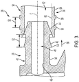
- Barb 42 is axially spaced from barb 44 by an axial distance (see arrow 52 in FIG. 3 ).
- the at least one barb 42, 44 is a plurality of barbs that is generally referred to as a fir tree arrangement.
- the female component 30 of the fuel connector 26 includes a segment 54 that may be tubular and at least one reinforcement ring (i.e., two illustrated as 56, 58).
- the tubular segment 54 includes an inner face 60 that defines a cavity 62 for receipt of the male component 28 in an axial direction with respect to the centerline C, and an opposite outer face 64 that faces radially outward with respect to the centerline C.
- each reinforcement ring 56, 58 is engaged to, and projects radially outward from the outer face 64.
- the reinforcement rings 56, 58 and the outer face 64 circumferentially extend continuously about the centerline C.
- Reinforcement ring 56 is axially spaced from the reinforcement ring 58 by the same axial distance 52 measured between the barbs 42, 44.
- the reinforcement rings 56, 58 provide increased strength to female component 30 at the location of reinforcement rings 56, 58, and therefore increased resistance to deformation, comparted to the portions of female component 30 that are immediately ahead of and behind reinforcement rings 56, 58.
- each barb 42, 44 is ramped for axial insertion (see arrow 66 representing an insertion direction in FIG. 3 ) of the male component 28 into the cavity 62 of the female component 30.
- apexes 68 of each barb 42, 44 are press fitted against the inner face 60 of the tubular segment 54 of the female component 30 for a fuel resistant seal.
- each one of the reinforcement rings 56, 58 are in a predefined axial relationship with a respective one of the barbs 42, 44 when connected.
- the reinforcement ring 58 is axially located behind the barb 44, and the reinforcement ring 56 is axially located behind the barb 42 (i.e., with respect to the insertion direction 66 of the male component 28).
- the reinforcement ring 58 is axially centered between the barbs 42, 44.
- the barbs 42, 44 and the tubular segment 54 of the female component 30 will undergo limited plastic deformation.
- the reinforcement rings 56, 58 are adapted to limit plastic deformation of the tubular segment 54, while providing an optimal seal.
- each barb 42, 44 may be, at least in part, resiliently deformed (i.e., flexed radially inward) because of the biased contact against the inner face 60 of the female component 30.
- the inner face 60 may be resiliently flexed radially outward because of the same contact.
- flexing of the inner face 60 i.e., that portion located axially between the reinforcement rings 56, 58), causes the entire wall of the tubular segment 54 of the female component 30 to flex, or distort radially outward. This flexing of the tubular segment 54 creates an external humped appearance of the tubular segment 54.
- Such humped appearances are axially aligned to the location of each respective barb 42, 44.
- the reinforcement rings 56, 58 act to limit, or restrict, the distortion of the tubular segment 54. That is, distortion of the tubular segment 54 at the axial locations of the reinforcement rings 56, 58 is minimal, or non-existent.
- a female component 30' of a fuel connector 26' includes a segment 54' that may be tubular and at least one reinforcement ring (i.e., two illustrated as 56', 58').
- the tubular segment 54' includes an inner face 60' that defines a cavity 62' for receipt of a male component 28', and an opposite outer face 64'.
- the reinforcement rings 56', 58' are embedded in the tubular segment 54' and between the faced 60', 64'.
- the reinforcement rings 56', 58' are made of a material that is stronger than the material of the tubular segment 54'.
- the tubular segment 54' may be made of injection molded plastic and the reinforcement rings 56', 58' may be made of metal (e.g., steel).
- the reinforcement rings 56', 58' provide increased strength to female component 30' at the location of reinforcement rings 56', 58', and therefore increased resistance to deformation, comparted to the portions of female component 30' that are immediately ahead of and behind reinforcement rings 56, 58
- Advantages and benefits of the present disclosure include a fuel connector that is easily coupled utilizing few part, and not requiring separate seals (e.g., O-rings), clamps and/or snaps, and separate hoses.
- Other advantages include a connector providing improved packaging (i.e., a compact design), a robust design and reduced costs.
Landscapes
- Engineering & Computer Science (AREA)
- General Engineering & Computer Science (AREA)
- Chemical & Material Sciences (AREA)
- Mechanical Engineering (AREA)
- Combustion & Propulsion (AREA)
- Chemical Kinetics & Catalysis (AREA)
- Fuel-Injection Apparatus (AREA)
- Quick-Acting Or Multi-Walled Pipe Joints (AREA)
Abstract
Description
- The present disclosure relates to a fuel system, and more particularly, to a reinforced fuel connector of the fuel system.
- Known fuel connectors include multiple parts such as O-rings, clamps, and/or snaps contributing toward costs and less than optimal packaging issues.
- Accordingly, it is desirable to provide a more robust fuel connector with less parts, reduced costs, and improvements in packaging.
- In one, exemplary and non-limiting, embodiment of the present disclosure, a fuel connector of a fuel system is adapted to flow fuel. The fuel system includes male and female components. The male component includes a plurality of barbs each projecting radially outward, spaced axially from one-another and being circumferentially continuous. The female component includes a plurality of reinforcement rings being in a predefined axial relationship with the respective plurality of barbs when connected.
- In the fuel connector, each one of the plurality of reinforcement rings may be axially located behind a respective one of the plurality of barbs and with respect to an insertion direction of the male component.
- Also in the fuel connector, the adjacent barbs of the plurality of barbs may be axially spaced by a first distance, adjacent reinforcement rings of the plurality of reinforcement rings may be axially spaced by a second distance, and the first distance may be equal to the second distance.
- Each ring of the plurality of rings may project radially outward.
- The male component may be a unitary, single, and homogenous piece made of plastic.
- The female component may be a unitary, single, and homogenous piece made of plastic.
- In the fuel connector, at least one of the male and female components may be made of acetal conductive copolymer.
- The plurality of barbs may form a fir tree.
- The male component of the fuel connector may include a tubular portion having an inner surface defining a channel for the flow of fuel and an opposite outer surface, and the plurality of barbs may project radially outward from the outer surface.
- The female component of the fuel connector may include a tubular segment having an inner face defining a cavity for receipt of the male component, and an opposite outer face, and the plurality of rings may project radially outward from the outer face.
- The female component of the fuel connector may include a tubular segment having an inner face defining a cavity for receipt of the male component, an opposite outer face, and the plurality of rings may be embedded in the tubular segment radially between the inner and outer faces.
- In another embodiment, a fuel connector is adapted to flow fuel, and includes a male component, and a female component. The male component includes a tubular portion and a circumferentially continuous barb. The male component defines a channel for the flow of fuel along a centerline. The barb projects radially outward from the tubular portion. The female component including a tubular segment and a reinforcement ring. The tubular segment defines a cavity extending along the centerline, and is adapted to receive the male component. The reinforcement ring is circumferentially continuous and projects radially outward from the tubular segment. The reinforcement ring is a unitary part of the tubular segment, and is axially located behind the barb when the fuel connector is coupled.
- The male and female components may be made of injection molded plastic.
- In another embodiment, a fuel system includes a fuel connector, a fuel filter, and a fuel fitting. The connector includes male and female components. The male component includes a tubular portion defining a channel for the flow of fuel along a centerline, and a circumferentially continuous barb projecting radially outward from the tubular portion. The female component includes a tubular segment and a reinforcement ring. The tubular segment defines a cavity extending along the centerline and adapted to receive the male component. The reinforcement ring is circumferentially continuous and projects radially outward from the tubular segment. The reinforcement ring is a unitary part of the tubular segment and is axially located behind the barb with respect to an insertion direction of the male component and when the first fuel connector is coupled. The fuel connector is carried between the fuel filter and the fuel fitting, thereby providing fluid communication between the fitting and the fuel filter.
- In the fuel system, the fuel filter may include a housing and one of the male and female components may be an integral and unitary part of the housing.
- In the fuel system, the other of the male and female components may be an integral and unitary part of the fitting.
- The fuel system may further comprise: a fuel pump in fluid communication with the fuel filter via the fitting, the fuel pump including a pump housing; and a second fuel connector including male and female components, the male component including a tubular portion defining a channel for the flow of fuel along a centerline and a circumferentially continuous barb projecting radially outward from the tubular portion, and the female component including a tubular segment defining a cavity extending along the centerline and adapted to receive the male component and a reinforcement ring being circumferentially continuous and projecting radially outward from the tubular segment, the reinforcement ring being a unitary part of the tubular segment and being in a predefined axial relationship with the barb when the second fuel connector is coupled, and one of the male and female components of the second fuel connector is an integral and unitary part of the pump housing.
- In the fuel system, the other of the male and female components of the second fuel connector may be an integral and unitary part of the fitting.
- Also in the fuel system, the circumferentially continuous barb may be one of a plurality of circumferentially continuous barbs axially spaced from one-another, and the reinforcement ring may be one of a plurality of reinforcement rings axially spaced from one-another, and wherein each one of the plurality of circumferentially continuous barbs may be axially located behind a respective one of the plurality of reinforcement rings and with respect to an insertion direction of the male component.
- These and other advantages and features will become more apparent from the following description taken in conjunction with the drawings.
- The subject matter which is regarded as the invention is particularly pointed out and distinctly claimed in the claims at the conclusion of the specification. The foregoing and other features, and advantages of the invention are apparent from the following detailed description taken in conjunction with the accompanying drawings in which:
-
FIG. 1 is a partial perspective view of a fuel system utilizing a fuel connector as one, non-limiting, exemplary embodiment of the present disclosure; -
FIG. 2 is a perspective cross section of the fuel system; -
FIG. 3 is a cross section of the fuel connector of the fuel system when partially connected; -
FIG. 4 is a cross section of the fuel connector when fully connected; and -
FIG. 5 is a cross section of a second embodiment of the fuel connector. - Referring now to the Figures, where the invention will be described with reference to specific embodiments, without limiting same, at least a portion of a
fuel system 20 is illustrated inFIG. 1 . As one, non-limiting, example, such fuel systems may be utilized in the automotive industry to deliver fuel to a combustion engine (not shown). In this and other applications, thefuel system 20 may include afuel pump 22 and afuel filter 24. - Referring to
FIGS. 1 and2 , to facilitate fuel flow from thefuel pump 22 to the fuel filter 24 (or vice-versa), thefuel system 20 includes afuel connector 26 that may be generally carried by, and between, the pump and the filter. Thefuel connector 26 includes amale component 28 and afemale component 30. In one embodiment, themale component 28 may be an integral and unitary part of afilter housing 32 of thefuel filter 24. Thefemale component 30 may be an integral and unitary part of amulti-ported fuel fitting 34 adapted, for example, to press fit about a fuelpump outlet nozzle 36 that may be an integral and unitary part of apump housing 38. In one embodiment, the fuelpump outlet nozzle 36 and the portion of the fuel fitting (i.e., port) that press fits to the fuelpump outlet nozzle 36 may be considered as a second fuel connection. In yet another embodiment, the fuel fitting 34 may be an integral and unitary part of thepump housing 38. - In other embodiments, the fuel fitting 34 may include one or more
male components 28 and/or one or morefemale components 30 adapted to connect to any number of fuel system elements. For example, the fitting illustrated inFIG. 1 includes thefemale component 30, as previously described, a second female component 35 adapted to connect to the fuel pump outlet nozzle 36 (i.e. male component) associated with thepump housing 38, and amale component 37 adapted to connect to a female component of a jet pump (not illustrated). - In one embodiment, the
filter housing 32 may be a unitary, single, and homogeneous part made, for example, of injection molded plastic. Similarly, the fuel fitting 34 may be a unitary, single, and homogeneous part made of injection molded plastic. In yet another example, one or both of thecomponents - Referring to
FIGS. 2 and3 , themale component 28 of thefuel connector 26 includes atubular portion 40 and at least one barb (i.e., two illustrated as 42, 44). Thetubular portion 40 includes an inner surface 46 that defines achannel 48 for the flow of fuel along a centerline C, and an opposite outer surface 50 that faces radially outward with respect to the centerline C. Eachbarb barbs centerline C. Barb 42 is axially spaced frombarb 44 by an axial distance (see arrow 52 inFIG. 3 ). In one embodiment, the at least onebarb - The
female component 30 of thefuel connector 26 includes asegment 54 that may be tubular and at least one reinforcement ring (i.e., two illustrated as 56, 58). Thetubular segment 54 includes aninner face 60 that defines acavity 62 for receipt of themale component 28 in an axial direction with respect to the centerline C, and an oppositeouter face 64 that faces radially outward with respect to the centerline C. In one example, eachreinforcement ring outer face 64. The reinforcement rings 56, 58 and theouter face 64 circumferentially extend continuously about the centerlineC. Reinforcement ring 56 is axially spaced from thereinforcement ring 58 by the same axial distance 52 measured between thebarbs female component 30 at the location of reinforcement rings 56, 58, and therefore increased resistance to deformation, comparted to the portions offemale component 30 that are immediately ahead of and behind reinforcement rings 56, 58. - Referring to
FIG. 3 , eachbarb FIG. 3 ) of themale component 28 into thecavity 62 of thefemale component 30. When thefuel connector 26 is fully coupled (as best shown inFIG. 4 ), apexes 68 of eachbarb inner face 60 of thetubular segment 54 of thefemale component 30 for a fuel resistant seal. - When the
fuel connector 26 is fully coupled, each one of the reinforcement rings 56, 58 are in a predefined axial relationship with a respective one of thebarbs reinforcement ring 58 is axially located behind thebarb 44, and thereinforcement ring 56 is axially located behind the barb 42 (i.e., with respect to the insertion direction 66 of the male component 28). In one embodiment, and when fully coupled, thereinforcement ring 58 is axially centered between thebarbs fuel connector 26 is fully coupled, thebarbs tubular segment 54 of thefemale component 30 will undergo limited plastic deformation. The reinforcement rings 56, 58 are adapted to limit plastic deformation of thetubular segment 54, while providing an optimal seal. - In one embodiment, and when the
fuel connector 26 is fully coupled, the apexes 68 of eachbarb inner face 60 of thefemale component 30. In addition, theinner face 60 may be resiliently flexed radially outward because of the same contact. In one example, flexing of the inner face 60 (i.e., that portion located axially between the reinforcement rings 56, 58), causes the entire wall of thetubular segment 54 of thefemale component 30 to flex, or distort radially outward. This flexing of thetubular segment 54 creates an external humped appearance of thetubular segment 54. Such humped appearances are axially aligned to the location of eachrespective barb tubular segment 54. That is, distortion of thetubular segment 54 at the axial locations of the reinforcement rings 56, 58 is minimal, or non-existent. - Referring to
FIG. 5 , a second embodiment of a fuel connector is illustrated wherein like elements to the first embodiment have like identifying numerals except with the addition of a prime symbol suffix. A female component 30' of a fuel connector 26' includes a segment 54' that may be tubular and at least one reinforcement ring (i.e., two illustrated as 56', 58'). The tubular segment 54' includes an inner face 60' that defines a cavity 62' for receipt of a male component 28', and an opposite outer face 64'. The reinforcement rings 56', 58' are embedded in the tubular segment 54' and between the faced 60', 64'. - The reinforcement rings 56', 58' are made of a material that is stronger than the material of the tubular segment 54'. For example, the tubular segment 54' may be made of injection molded plastic and the reinforcement rings 56', 58' may be made of metal (e.g., steel). The reinforcement rings 56', 58' provide increased strength to female component 30' at the location of reinforcement rings 56', 58', and therefore increased resistance to deformation, comparted to the portions of female component 30' that are immediately ahead of and behind reinforcement rings 56, 58
- Advantages and benefits of the present disclosure include a fuel connector that is easily coupled utilizing few part, and not requiring separate seals (e.g., O-rings), clamps and/or snaps, and separate hoses. Other advantages include a connector providing improved packaging (i.e., a compact design), a robust design and reduced costs.
- While the invention has been described in detail in connection with only a limited number of embodiments, it should be readily understood that the invention is not limited to such disclosed embodiments. Rather, the invention can be modified to incorporate any number of variations, alterations, substitutions or equivalent arrangements not heretofore described, but which are commensurate with the spirit and scope of the invention. Additionally, while various embodiments of the invention have been described, it is to be understood that aspects of the invention may include only some of the described embodiments. Accordingly, the invention is not to be seen as limited by the foregoing description.
Claims (19)
- A fuel connector (26) adapted to flow fuel, the fuel connector (26) comprising:a male component (28) including a plurality of barbs (42,44) each projecting radially outward, spaced axially from one-another and being circumferentially continuous; anda female component (30) including a plurality of reinforcement rings (56,58), each one of the plurality of reinforcement rings (56,58) being in a predefined axial relationship with a respective one of the plurality of barbs (42,44) when connected.
- The fuel connector (26) set forth in claim 1, wherein each one of the plurality of reinforcement rings (56,58) is axially located behind a respective one of the plurality of barbs (42,44) and with respect to an insertion direction (66) of the male component (28).
- The fuel connector (26) set forth in claims 1 and 2, wherein adjacent barbs (42,44) of the plurality of barbs (42,44) are axially spaced by a first distance (52), adjacent reinforcement rings (56,58) of the plurality of reinforcement rings (56,58) are axially spaced by a second distance (52), and the first distance (52) is equal to the second distance (52).
- The fuel connector (26) set forth in all previous claims, wherein each ring of the plurality of rings (56,58) project radially outward.
- The fuel connector (26) set forth in claim 4, wherein the male component (28) is a unitary, single, and homogenous piece made of plastic.
- The fuel connector (26) set forth in claim 5, wherein the female component (30) is a unitary, single, and homogenous piece made of plastic.
- The fuel connector (26) set forth in claim 4, wherein at least one of the male and female components (28,30) are made of acetal conductive copolymer.
- The fuel connector (26) set forth in claim 4, wherein the plurality of barbs (42,44) form a fir tree.
- The fuel connector (26) set forth in claim 4, wherein the male component (28) includes a tubular portion (40) having an inner surface (46) defining a channel (48) for the flow of fuel and an opposite outer surface (50), and the plurality of barbs (42,44) project radially outward from the outer surface (50).
- The fuel connector (26) set forth in claim 9, wherein the female component (30) includes a tubular segment (54) having an inner face (60) defining a cavity (62) for receipt of the male component (28), and an opposite outer face (64), and the plurality of rings (56,58) project radially outward from the outer face (64).
- The fuel connector (26) set forth in claim 1, wherein the female component (30) includes a tubular segment (54) having an inner face (60) defining a cavity (62) for receipt of the male component (28), an opposite outer face (64), and the plurality of rings are embedded in the tubular segment (54) radially between the inner and outer faces.
- A fuel connector (26) adapted to flow fuel, the fuel connector (26) comprising:a male component (28) including a tubular portion (40) defining a channel (48) for the flow of fuel along a centerline, and a circumferentially continuous barb (42,44) projecting radially outward from the tubular portion (40); anda female component (30) including a tubular segment (54) defining a cavity (62) extending along the centerline and adapted to receive the male component (28), and a reinforcement ring (56,58) being circumferentially continuous and projecting radially outward from the tubular segment (54), the reinforcement ring (56,58) being a unitary part of the tubular segment (54) and axially located behind the barb (42,44) with respect to an insertion direction (66) of the male component (28) and when the fuel connector (26) is coupled.
- The fuel connector (26) set forth in claim 12, wherein the male and female components (28,30) are made of injection molded plastic.
- A fuel system (20) comprising:a first fuel connector (26) including male and female components (30), the male component (28) including a tubular portion (40) defining a channel (48) for the flow of fuel along a centerline and a circumferentially continuous barb (42,44) projecting radially outward from the tubular portion (40), and the female component (30) including a tubular segment (54) defining a cavity (62) extending along the centerline and adapted to receive the male component (28) and a reinforcement ring (56,58) being circumferentially continuous and projecting radially outward from the tubular segment (54), the reinforcement ring (56,58) being a unitary part of the tubular segment (54) and axially located behind the barb (42,44) with respect to an insertion direction (66) of the male component (28) and when the first fuel connector (26) is coupled;a fuel filter (24); anda fuel fitting (34), the first fuel connector (26) being carried between the fuel filter (24) and the fuel fitting (34) providing fluid communication between the fitting and the fuel filter (24).
- The fuel system (20) set forth in claim 14, wherein the fuel filter (24) includes a housing (32) and one of the male and female components (30) is an integral and unitary part of the housing.
- The fuel system (20) set forth in claim 15, wherein the other of the male and female components (28,30) is an integral and unitary part of the fitting (34).
- The fuel system (20) set forth in claim 16, further comprising:a fuel pump (22) in fluid communication with the fuel filter (24) via the fitting (34), the fuel pump (22) including a pump housing (38); anda second fuel connector including male and female components (35), the male component (36) including a tubular portion (40) defining a channel for the flow of fuel along a centerline and a circumferentially continuous barb projecting radially outward from the tubular portion, and the female component (35) including a tubular segment defining a cavity extending along the centerline and adapted to receive the male component (36) and a reinforcement ring being circumferentially continuous and projecting radially outward from the tubular segment, the reinforcement ring being a unitary part of the tubular segment and being in a predefined axial relationship with the barb when the second fuel connector is coupled, and one of the male and female components (35,36) of the second fuel connector is an integral and unitary part of the pump housing (38).
- The fuel system (20) set forth in claim 17, wherein the other of the male and female components (35,36) of the second fuel connector is an integral and unitary part of the fitting (34).
- The fuel system (20) set forth in claim 14, wherein the circumferentially continuous barb (42,44) is one of a plurality of circumferentially continuous barbs (42,44) axially spaced from one-another, and the reinforcement ring (56,58) is one of a plurality of reinforcement rings (56,58) axially spaced from one-another, and wherein each one of the plurality of circumferentially continuous barbs (42,44) are axially located behind a respective one of the plurality of reinforcement rings (56,58) and with respect to an insertion direction (66) of the male component (28).
Applications Claiming Priority (1)
| Application Number | Priority Date | Filing Date | Title |
|---|---|---|---|
| US16/287,441 US11391398B2 (en) | 2019-02-27 | 2019-02-27 | Fuel system including reinforced fuel connector with retaining rings |
Publications (2)
| Publication Number | Publication Date |
|---|---|
| EP3702607A1 true EP3702607A1 (en) | 2020-09-02 |
| EP3702607B1 EP3702607B1 (en) | 2025-03-19 |
Family
ID=69845776
Family Applications (1)
| Application Number | Title | Priority Date | Filing Date |
|---|---|---|---|
| EP20158495.0A Active EP3702607B1 (en) | 2019-02-27 | 2020-02-20 | Reinforced fuel connector with retaining rings and fuel system including reinforced fuel connector with retaining rings |
Country Status (2)
| Country | Link |
|---|---|
| US (1) | US11391398B2 (en) |
| EP (1) | EP3702607B1 (en) |
Citations (10)
| Publication number | Priority date | Publication date | Assignee | Title |
|---|---|---|---|---|
| DE3543717A1 (en) * | 1985-12-11 | 1987-06-19 | Muhr & Bender | Hose connection |
| US4972875A (en) * | 1989-12-26 | 1990-11-27 | General Motors Corporation | High pressure hose for modular fuel delivery system |
| DE29720516U1 (en) * | 1997-11-19 | 1998-02-19 | Gossler Fluidtec GmbH, 21465 Reinbek | Hose fitting |
| DE19642580A1 (en) * | 1996-10-15 | 1998-06-04 | Muhr & Bender | Connector-hose connection |
| US6155302A (en) * | 1996-01-27 | 2000-12-05 | Robert Bosch Gmbh | Fastening device for attaching a fuel line to a connecting piece |
| US20020053567A1 (en) * | 2000-11-08 | 2002-05-09 | Beyer Sharon Elizabeth | In-tank fuel line quick connector assembly |
| US20040195830A1 (en) * | 2003-04-01 | 2004-10-07 | Gilmour Daniel A. | Injection molded coupling for fuel system components |
| DE102008004152A1 (en) * | 2007-02-03 | 2008-08-07 | Luk Lamellen Und Kupplungsbau Beteiligungs Kg | Pipe with a connection piece |
| DE102012223994A1 (en) * | 2012-12-20 | 2014-06-26 | Robert Bosch Gmbh | Wire-connecting apparatus of connector, for medium-carrying pipe e.g. fuel pipe, has elastically formed layer that is provided at external periphery of connecting piece and is engaged around external periphery of connecting piece |
| US20160028176A1 (en) * | 2014-07-26 | 2016-01-28 | Audi Ag | Line system for a vehicle |
Family Cites Families (11)
| Publication number | Priority date | Publication date | Assignee | Title |
|---|---|---|---|---|
| US4537183A (en) * | 1983-04-08 | 1985-08-27 | Mentor Corporation | Connector device for connecting elastic tubing of an implantable device |
| US4826477A (en) * | 1986-09-19 | 1989-05-02 | Abiomed Cardiovascular, Inc. | Connector for blood handling systems |
| US5312138A (en) | 1992-07-17 | 1994-05-17 | Whirlpool Corporation | Drain hose assembly for an automatic washer |
| DE19932956B4 (en) * | 1998-07-15 | 2009-04-09 | Toyoda Gosei Co., Ltd. | hose connection |
| US6588449B1 (en) | 2000-08-31 | 2003-07-08 | Saturn Electronics & Engineering, Inc. | Diesel fuel shut-off device |
| US6609732B1 (en) * | 2002-02-01 | 2003-08-26 | General Motors Corporation | Quick connect multi-hose connector |
| JP2004211811A (en) * | 2002-12-27 | 2004-07-29 | Tokai Rubber Ind Ltd | Piping connection structure for connecting tubes and hoses |
| US7108291B2 (en) * | 2003-05-07 | 2006-09-19 | Parker-Hannifin | Clip coupling |
| JP2006200737A (en) * | 2004-12-24 | 2006-08-03 | Tokai Rubber Ind Ltd | Connection pipe |
| US20080087349A1 (en) | 2006-09-21 | 2008-04-17 | Siemens Vdo Automotive Corporation | Molded tube for vehicle fuel delivery module |
| US8342578B2 (en) * | 2008-12-17 | 2013-01-01 | Bobenhausen Larry F | Method and apparatus for connecting a hose to a fitting |
-
2019
- 2019-02-27 US US16/287,441 patent/US11391398B2/en active Active
-
2020
- 2020-02-20 EP EP20158495.0A patent/EP3702607B1/en active Active
Patent Citations (10)
| Publication number | Priority date | Publication date | Assignee | Title |
|---|---|---|---|---|
| DE3543717A1 (en) * | 1985-12-11 | 1987-06-19 | Muhr & Bender | Hose connection |
| US4972875A (en) * | 1989-12-26 | 1990-11-27 | General Motors Corporation | High pressure hose for modular fuel delivery system |
| US6155302A (en) * | 1996-01-27 | 2000-12-05 | Robert Bosch Gmbh | Fastening device for attaching a fuel line to a connecting piece |
| DE19642580A1 (en) * | 1996-10-15 | 1998-06-04 | Muhr & Bender | Connector-hose connection |
| DE29720516U1 (en) * | 1997-11-19 | 1998-02-19 | Gossler Fluidtec GmbH, 21465 Reinbek | Hose fitting |
| US20020053567A1 (en) * | 2000-11-08 | 2002-05-09 | Beyer Sharon Elizabeth | In-tank fuel line quick connector assembly |
| US20040195830A1 (en) * | 2003-04-01 | 2004-10-07 | Gilmour Daniel A. | Injection molded coupling for fuel system components |
| DE102008004152A1 (en) * | 2007-02-03 | 2008-08-07 | Luk Lamellen Und Kupplungsbau Beteiligungs Kg | Pipe with a connection piece |
| DE102012223994A1 (en) * | 2012-12-20 | 2014-06-26 | Robert Bosch Gmbh | Wire-connecting apparatus of connector, for medium-carrying pipe e.g. fuel pipe, has elastically formed layer that is provided at external periphery of connecting piece and is engaged around external periphery of connecting piece |
| US20160028176A1 (en) * | 2014-07-26 | 2016-01-28 | Audi Ag | Line system for a vehicle |
Also Published As
| Publication number | Publication date |
|---|---|
| US11391398B2 (en) | 2022-07-19 |
| EP3702607B1 (en) | 2025-03-19 |
| US20200271250A1 (en) | 2020-08-27 |
Similar Documents
| Publication | Publication Date | Title |
|---|---|---|
| EP3467367B1 (en) | Anti-tamper permanent quick connect coupling device | |
| US8297659B2 (en) | Quick connector assembly | |
| US6543814B2 (en) | Quick connector | |
| US5542717A (en) | Quick connect coupling | |
| KR101849152B1 (en) | Lock for a tubular connection | |
| US9121533B2 (en) | Crankcase ventilation for an internal combustion engine, tank ventilation conduit and connection system therefor | |
| EP3584489B1 (en) | Coupling arrangement and connector for a coupling arrangement | |
| US20150159792A1 (en) | Self-locking push-to-connect insert | |
| EP2867516B1 (en) | Fuel line connector | |
| US7731245B2 (en) | Quick connector coupling | |
| WO2003083346A1 (en) | Fluid conduit quick connector and stuffer pack | |
| EP4249786B1 (en) | Sealing bushing for a connector for distributing a fluid | |
| EP3702607B1 (en) | Reinforced fuel connector with retaining rings and fuel system including reinforced fuel connector with retaining rings | |
| EP3803183B1 (en) | Quick connector | |
| US11920716B2 (en) | Fluid connector | |
| EP1650485A2 (en) | Coupling assembly with connection indicator | |
| EP3842678A1 (en) | Tube connector | |
| US8070187B2 (en) | Interface hose seal for low permeation flange of a fuel supply unit | |
| EP3353406B1 (en) | Segmented manifold head connectors | |
| JP4712423B2 (en) | Quick connector | |
| JP2000320746A (en) | Nut for connecting pressure line | |
| US20060141869A1 (en) | Tube for transporting fluid | |
| JP4982321B2 (en) | Quick connector | |
| US20210180734A1 (en) | Connection arrangement for a fluid transfer interface | |
| US12601434B2 (en) | Fluid connection assembly |
Legal Events
| Date | Code | Title | Description |
|---|---|---|---|
| PUAI | Public reference made under article 153(3) epc to a published international application that has entered the european phase |
Free format text: ORIGINAL CODE: 0009012 |
|
| STAA | Information on the status of an ep patent application or granted ep patent |
Free format text: STATUS: THE APPLICATION HAS BEEN PUBLISHED |
|
| AK | Designated contracting states |
Kind code of ref document: A1 Designated state(s): AL AT BE BG CH CY CZ DE DK EE ES FI FR GB GR HR HU IE IS IT LI LT LU LV MC MK MT NL NO PL PT RO RS SE SI SK SM TR |
|
| AX | Request for extension of the european patent |
Extension state: BA ME |
|
| STAA | Information on the status of an ep patent application or granted ep patent |
Free format text: STATUS: REQUEST FOR EXAMINATION WAS MADE |
|
| 17P | Request for examination filed |
Effective date: 20210302 |
|
| RBV | Designated contracting states (corrected) |
Designated state(s): AL AT BE BG CH CY CZ DE DK EE ES FI FR GB GR HR HU IE IS IT LI LT LU LV MC MK MT NL NO PL PT RO RS SE SI SK SM TR |
|
| STAA | Information on the status of an ep patent application or granted ep patent |
Free format text: STATUS: EXAMINATION IS IN PROGRESS |
|
| 17Q | First examination report despatched |
Effective date: 20221025 |
|
| P01 | Opt-out of the competence of the unified patent court (upc) registered |
Effective date: 20230327 |
|
| RAP1 | Party data changed (applicant data changed or rights of an application transferred) |
Owner name: PHINIA DELPHI LUXEMBOURG SARL |
|
| RIC1 | Information provided on ipc code assigned before grant |
Ipc: F16L 33/22 20060101ALN20240906BHEP Ipc: F02M 37/00 20060101AFI20240906BHEP |
|
| GRAP | Despatch of communication of intention to grant a patent |
Free format text: ORIGINAL CODE: EPIDOSNIGR1 |
|
| STAA | Information on the status of an ep patent application or granted ep patent |
Free format text: STATUS: GRANT OF PATENT IS INTENDED |
|
| RIC1 | Information provided on ipc code assigned before grant |
Ipc: F16L 33/22 20060101ALN20240930BHEP Ipc: F02M 37/00 20060101AFI20240930BHEP |
|
| INTG | Intention to grant announced |
Effective date: 20241024 |
|
| GRAS | Grant fee paid |
Free format text: ORIGINAL CODE: EPIDOSNIGR3 |
|
| GRAA | (expected) grant |
Free format text: ORIGINAL CODE: 0009210 |
|
| STAA | Information on the status of an ep patent application or granted ep patent |
Free format text: STATUS: THE PATENT HAS BEEN GRANTED |
|
| AK | Designated contracting states |
Kind code of ref document: B1 Designated state(s): AL AT BE BG CH CY CZ DE DK EE ES FI FR GB GR HR HU IE IS IT LI LT LU LV MC MK MT NL NO PL PT RO RS SE SI SK SM TR |
|
| REG | Reference to a national code |
Ref country code: GB Ref legal event code: FG4D |
|
| REG | Reference to a national code |
Ref country code: CH Ref legal event code: EP |
|
| REG | Reference to a national code |
Ref country code: IE Ref legal event code: FG4D |
|
| REG | Reference to a national code |
Ref country code: DE Ref legal event code: R096 Ref document number: 602020047808 Country of ref document: DE |
|
| PG25 | Lapsed in a contracting state [announced via postgrant information from national office to epo] |
Ref country code: RS Free format text: LAPSE BECAUSE OF FAILURE TO SUBMIT A TRANSLATION OF THE DESCRIPTION OR TO PAY THE FEE WITHIN THE PRESCRIBED TIME-LIMIT Effective date: 20250619 |
|
| PG25 | Lapsed in a contracting state [announced via postgrant information from national office to epo] |
Ref country code: FI Free format text: LAPSE BECAUSE OF FAILURE TO SUBMIT A TRANSLATION OF THE DESCRIPTION OR TO PAY THE FEE WITHIN THE PRESCRIBED TIME-LIMIT Effective date: 20250319 |
|
| REG | Reference to a national code |
Ref country code: LT Ref legal event code: MG9D |
|
| PG25 | Lapsed in a contracting state [announced via postgrant information from national office to epo] |
Ref country code: NO Free format text: LAPSE BECAUSE OF FAILURE TO SUBMIT A TRANSLATION OF THE DESCRIPTION OR TO PAY THE FEE WITHIN THE PRESCRIBED TIME-LIMIT Effective date: 20250619 |
|
| PG25 | Lapsed in a contracting state [announced via postgrant information from national office to epo] |
Ref country code: HR Free format text: LAPSE BECAUSE OF FAILURE TO SUBMIT A TRANSLATION OF THE DESCRIPTION OR TO PAY THE FEE WITHIN THE PRESCRIBED TIME-LIMIT Effective date: 20250319 |
|
| PG25 | Lapsed in a contracting state [announced via postgrant information from national office to epo] |
Ref country code: LV Free format text: LAPSE BECAUSE OF FAILURE TO SUBMIT A TRANSLATION OF THE DESCRIPTION OR TO PAY THE FEE WITHIN THE PRESCRIBED TIME-LIMIT Effective date: 20250319 |
|
| PG25 | Lapsed in a contracting state [announced via postgrant information from national office to epo] |
Ref country code: GR Free format text: LAPSE BECAUSE OF FAILURE TO SUBMIT A TRANSLATION OF THE DESCRIPTION OR TO PAY THE FEE WITHIN THE PRESCRIBED TIME-LIMIT Effective date: 20250620 Ref country code: BG Free format text: LAPSE BECAUSE OF FAILURE TO SUBMIT A TRANSLATION OF THE DESCRIPTION OR TO PAY THE FEE WITHIN THE PRESCRIBED TIME-LIMIT Effective date: 20250319 |
|
| REG | Reference to a national code |
Ref country code: NL Ref legal event code: MP Effective date: 20250319 |
|
| REG | Reference to a national code |
Ref country code: AT Ref legal event code: MK05 Ref document number: 1777136 Country of ref document: AT Kind code of ref document: T Effective date: 20250319 |
|
| PG25 | Lapsed in a contracting state [announced via postgrant information from national office to epo] |
Ref country code: NL Free format text: LAPSE BECAUSE OF FAILURE TO SUBMIT A TRANSLATION OF THE DESCRIPTION OR TO PAY THE FEE WITHIN THE PRESCRIBED TIME-LIMIT Effective date: 20250319 |
|
| PG25 | Lapsed in a contracting state [announced via postgrant information from national office to epo] |
Ref country code: SE Free format text: LAPSE BECAUSE OF FAILURE TO SUBMIT A TRANSLATION OF THE DESCRIPTION OR TO PAY THE FEE WITHIN THE PRESCRIBED TIME-LIMIT Effective date: 20250319 |
|
| PG25 | Lapsed in a contracting state [announced via postgrant information from national office to epo] |
Ref country code: SM Free format text: LAPSE BECAUSE OF FAILURE TO SUBMIT A TRANSLATION OF THE DESCRIPTION OR TO PAY THE FEE WITHIN THE PRESCRIBED TIME-LIMIT Effective date: 20250319 |
|
| PG25 | Lapsed in a contracting state [announced via postgrant information from national office to epo] |
Ref country code: ES Free format text: LAPSE BECAUSE OF FAILURE TO SUBMIT A TRANSLATION OF THE DESCRIPTION OR TO PAY THE FEE WITHIN THE PRESCRIBED TIME-LIMIT Effective date: 20250319 Ref country code: PT Free format text: LAPSE BECAUSE OF FAILURE TO SUBMIT A TRANSLATION OF THE DESCRIPTION OR TO PAY THE FEE WITHIN THE PRESCRIBED TIME-LIMIT Effective date: 20250721 |
|
| PG25 | Lapsed in a contracting state [announced via postgrant information from national office to epo] |
Ref country code: PL Free format text: LAPSE BECAUSE OF FAILURE TO SUBMIT A TRANSLATION OF THE DESCRIPTION OR TO PAY THE FEE WITHIN THE PRESCRIBED TIME-LIMIT Effective date: 20250319 Ref country code: IT Free format text: LAPSE BECAUSE OF FAILURE TO SUBMIT A TRANSLATION OF THE DESCRIPTION OR TO PAY THE FEE WITHIN THE PRESCRIBED TIME-LIMIT Effective date: 20250319 |
|
| PG25 | Lapsed in a contracting state [announced via postgrant information from national office to epo] |
Ref country code: AT Free format text: LAPSE BECAUSE OF FAILURE TO SUBMIT A TRANSLATION OF THE DESCRIPTION OR TO PAY THE FEE WITHIN THE PRESCRIBED TIME-LIMIT Effective date: 20250319 |
|
| PG25 | Lapsed in a contracting state [announced via postgrant information from national office to epo] |
Ref country code: CZ Free format text: LAPSE BECAUSE OF FAILURE TO SUBMIT A TRANSLATION OF THE DESCRIPTION OR TO PAY THE FEE WITHIN THE PRESCRIBED TIME-LIMIT Effective date: 20250319 Ref country code: EE Free format text: LAPSE BECAUSE OF FAILURE TO SUBMIT A TRANSLATION OF THE DESCRIPTION OR TO PAY THE FEE WITHIN THE PRESCRIBED TIME-LIMIT Effective date: 20250319 |
|
| PG25 | Lapsed in a contracting state [announced via postgrant information from national office to epo] |
Ref country code: RO Free format text: LAPSE BECAUSE OF FAILURE TO SUBMIT A TRANSLATION OF THE DESCRIPTION OR TO PAY THE FEE WITHIN THE PRESCRIBED TIME-LIMIT Effective date: 20250319 |
|
| PG25 | Lapsed in a contracting state [announced via postgrant information from national office to epo] |
Ref country code: SK Free format text: LAPSE BECAUSE OF FAILURE TO SUBMIT A TRANSLATION OF THE DESCRIPTION OR TO PAY THE FEE WITHIN THE PRESCRIBED TIME-LIMIT Effective date: 20250319 |
|
| PG25 | Lapsed in a contracting state [announced via postgrant information from national office to epo] |
Ref country code: IS Free format text: LAPSE BECAUSE OF FAILURE TO SUBMIT A TRANSLATION OF THE DESCRIPTION OR TO PAY THE FEE WITHIN THE PRESCRIBED TIME-LIMIT Effective date: 20250719 |
|
| REG | Reference to a national code |
Ref country code: DE Ref legal event code: R097 Ref document number: 602020047808 Country of ref document: DE |
|
| PG25 | Lapsed in a contracting state [announced via postgrant information from national office to epo] |
Ref country code: DK Free format text: LAPSE BECAUSE OF FAILURE TO SUBMIT A TRANSLATION OF THE DESCRIPTION OR TO PAY THE FEE WITHIN THE PRESCRIBED TIME-LIMIT Effective date: 20250319 |
|
| PLBE | No opposition filed within time limit |
Free format text: ORIGINAL CODE: 0009261 |
|
| STAA | Information on the status of an ep patent application or granted ep patent |
Free format text: STATUS: NO OPPOSITION FILED WITHIN TIME LIMIT |
|
| REG | Reference to a national code |
Ref country code: CH Ref legal event code: L10 Free format text: ST27 STATUS EVENT CODE: U-0-0-L10-L00 (AS PROVIDED BY THE NATIONAL OFFICE) Effective date: 20260128 |
|
| 26N | No opposition filed |
Effective date: 20251222 |
|
| PGFP | Annual fee paid to national office [announced via postgrant information from national office to epo] |
Ref country code: GB Payment date: 20260113 Year of fee payment: 7 |
|
| PGFP | Annual fee paid to national office [announced via postgrant information from national office to epo] |
Ref country code: DE Payment date: 20260115 Year of fee payment: 7 |
|
| PGFP | Annual fee paid to national office [announced via postgrant information from national office to epo] |
Ref country code: FR Payment date: 20260109 Year of fee payment: 7 |