EP3702597A1 - Engine system - Google Patents
Engine system Download PDFInfo
- Publication number
- EP3702597A1 EP3702597A1 EP18870605.5A EP18870605A EP3702597A1 EP 3702597 A1 EP3702597 A1 EP 3702597A1 EP 18870605 A EP18870605 A EP 18870605A EP 3702597 A1 EP3702597 A1 EP 3702597A1
- Authority
- EP
- European Patent Office
- Prior art keywords
- piston
- engine system
- detector
- cylinder
- cylinder liner
- Prior art date
- Legal status (The legal status is an assumption and is not a legal conclusion. Google has not performed a legal analysis and makes no representation as to the accuracy of the status listed.)
- Granted
Links
- 238000001514 detection method Methods 0.000 claims abstract description 43
- 230000006835 compression Effects 0.000 claims abstract description 33
- 238000007906 compression Methods 0.000 claims abstract description 33
- 239000012530 fluid Substances 0.000 claims abstract description 13
- 230000002000 scavenging effect Effects 0.000 claims description 25
- 238000002485 combustion reaction Methods 0.000 claims description 24
- 239000003921 oil Substances 0.000 description 30
- 239000000446 fuel Substances 0.000 description 21
- 230000033001 locomotion Effects 0.000 description 16
- 230000002093 peripheral effect Effects 0.000 description 11
- 239000007789 gas Substances 0.000 description 9
- 238000003780 insertion Methods 0.000 description 7
- 230000037431 insertion Effects 0.000 description 7
- 238000009434 installation Methods 0.000 description 6
- 239000007788 liquid Substances 0.000 description 6
- VNWKTOKETHGBQD-UHFFFAOYSA-N methane Chemical compound C VNWKTOKETHGBQD-UHFFFAOYSA-N 0.000 description 4
- 230000001276 controlling effect Effects 0.000 description 3
- 239000000295 fuel oil Substances 0.000 description 3
- 230000006870 function Effects 0.000 description 3
- 238000002347 injection Methods 0.000 description 3
- 239000007924 injection Substances 0.000 description 3
- 238000004891 communication Methods 0.000 description 2
- 238000001816 cooling Methods 0.000 description 2
- 230000009977 dual effect Effects 0.000 description 2
- 230000001965 increasing effect Effects 0.000 description 2
- 238000012544 monitoring process Methods 0.000 description 2
- 239000003345 natural gas Substances 0.000 description 2
- 230000001105 regulatory effect Effects 0.000 description 2
- 230000005540 biological transmission Effects 0.000 description 1
- 230000007423 decrease Effects 0.000 description 1
- 230000003247 decreasing effect Effects 0.000 description 1
- 238000013461 design Methods 0.000 description 1
- 238000010586 diagram Methods 0.000 description 1
- 230000000694 effects Effects 0.000 description 1
- 230000001939 inductive effect Effects 0.000 description 1
- 239000010687 lubricating oil Substances 0.000 description 1
- 238000000034 method Methods 0.000 description 1
- 238000012986 modification Methods 0.000 description 1
- 230000004048 modification Effects 0.000 description 1
- 238000012545 processing Methods 0.000 description 1
- 230000010349 pulsation Effects 0.000 description 1
- 239000007787 solid Substances 0.000 description 1
- 239000000243 solution Substances 0.000 description 1
Images


Classifications
-
- F—MECHANICAL ENGINEERING; LIGHTING; HEATING; WEAPONS; BLASTING
- F02—COMBUSTION ENGINES; HOT-GAS OR COMBUSTION-PRODUCT ENGINE PLANTS
- F02B—INTERNAL-COMBUSTION PISTON ENGINES; COMBUSTION ENGINES IN GENERAL
- F02B75/00—Other engines
- F02B75/04—Engines with variable distances between pistons at top dead-centre positions and cylinder heads
-
- F—MECHANICAL ENGINEERING; LIGHTING; HEATING; WEAPONS; BLASTING
- F02—COMBUSTION ENGINES; HOT-GAS OR COMBUSTION-PRODUCT ENGINE PLANTS
- F02B—INTERNAL-COMBUSTION PISTON ENGINES; COMBUSTION ENGINES IN GENERAL
- F02B25/00—Engines characterised by using fresh charge for scavenging cylinders
- F02B25/02—Engines characterised by using fresh charge for scavenging cylinders using unidirectional scavenging
- F02B25/04—Engines having ports both in cylinder head and in cylinder wall near bottom of piston stroke
-
- F—MECHANICAL ENGINEERING; LIGHTING; HEATING; WEAPONS; BLASTING
- F02—COMBUSTION ENGINES; HOT-GAS OR COMBUSTION-PRODUCT ENGINE PLANTS
- F02B—INTERNAL-COMBUSTION PISTON ENGINES; COMBUSTION ENGINES IN GENERAL
- F02B75/00—Other engines
- F02B75/04—Engines with variable distances between pistons at top dead-centre positions and cylinder heads
- F02B75/045—Engines with variable distances between pistons at top dead-centre positions and cylinder heads by means of a variable connecting rod length
-
- F—MECHANICAL ENGINEERING; LIGHTING; HEATING; WEAPONS; BLASTING
- F02—COMBUSTION ENGINES; HOT-GAS OR COMBUSTION-PRODUCT ENGINE PLANTS
- F02D—CONTROLLING COMBUSTION ENGINES
- F02D15/00—Varying compression ratio
- F02D15/02—Varying compression ratio by alteration or displacement of piston stroke
-
- F—MECHANICAL ENGINEERING; LIGHTING; HEATING; WEAPONS; BLASTING
- F16—ENGINEERING ELEMENTS AND UNITS; GENERAL MEASURES FOR PRODUCING AND MAINTAINING EFFECTIVE FUNCTIONING OF MACHINES OR INSTALLATIONS; THERMAL INSULATION IN GENERAL
- F16J—PISTONS; CYLINDERS; SEALINGS
- F16J1/00—Pistons; Trunk pistons; Plungers
- F16J1/02—Bearing surfaces
-
- F—MECHANICAL ENGINEERING; LIGHTING; HEATING; WEAPONS; BLASTING
- F02—COMBUSTION ENGINES; HOT-GAS OR COMBUSTION-PRODUCT ENGINE PLANTS
- F02B—INTERNAL-COMBUSTION PISTON ENGINES; COMBUSTION ENGINES IN GENERAL
- F02B75/00—Other engines
- F02B75/32—Engines characterised by connections between pistons and main shafts and not specific to preceding main groups
-
- Y—GENERAL TAGGING OF NEW TECHNOLOGICAL DEVELOPMENTS; GENERAL TAGGING OF CROSS-SECTIONAL TECHNOLOGIES SPANNING OVER SEVERAL SECTIONS OF THE IPC; TECHNICAL SUBJECTS COVERED BY FORMER USPC CROSS-REFERENCE ART COLLECTIONS [XRACs] AND DIGESTS
- Y02—TECHNOLOGIES OR APPLICATIONS FOR MITIGATION OR ADAPTATION AGAINST CLIMATE CHANGE
- Y02T—CLIMATE CHANGE MITIGATION TECHNOLOGIES RELATED TO TRANSPORTATION
- Y02T10/00—Road transport of goods or passengers
- Y02T10/10—Internal combustion engine [ICE] based vehicles
- Y02T10/12—Improving ICE efficiencies
Definitions
- the present disclosure relates to an engine system.
- Patent Document 1 discloses a large reciprocating piston combustion engine having a crosshead.
- the large reciprocating piston combustion engine of Patent Document 1 is a dual fuel engine capable of operating on both a liquid fuel such as heavy oil and a gas fuel such as natural gas.
- a crosshead portion is provided with an adjustment mechanism for changing the compression ratio by moving a piston rod using hydraulic pressure.
- Patent Document 1 Japanese Unexamined Patent Application, First Publication No. 2014-20375
- the above-described engine system with a compression adjustment device that changes the compression ratio changes the position of the piston rod in the movement direction thereof, thereby changing the bottom dead center position and the top dead center position of the piston and adjusting the compression ratio.
- Such an adjustment of the compression ratio is performed by a control device of the engine system based on an operation of an operator or the like.
- the control device cannot acquire the position of the piston rod, and it may be difficult to accurately adjust the compression ratio.
- the present disclosure is made in view of the above-described problems and an object thereof is to accurately acquire the compression ratio in an engine system with a variable compression device.
- An engine system of a first aspect of the present disclosure includes: a variable compression device including a fluid chamber in which a piston rod connected to a piston is moved in a direction to increase a compression ratio by a pressurized working fluid being supplied thereto; a detection device that outputs a signal including positional information of the piston; and a position acquisition device that acquires a position of the piston based on the signal.
- a second aspect of the present disclosure is that in the first aspect, at least part of the detection device is provided in a cylinder liner inside which the piston slides, and the detection device is configured to detect a position in a sliding direction of the piston.
- a third aspect of the present disclosure is that in the second aspect, the detection device includes a detection target provided in the piston and a detector provided in the cylinder liner.
- a fourth aspect of the present disclosure is that in the third aspect, the detection target includes a plurality of detection targets provided on a sliding surface of the piston in a circumferential direction.
- a fifth aspect of the present disclosure is that in the third or fourth aspect, the detector is provided at a position farther than a scavenging port of the cylinder liner with respect to a combustion chamber in the sliding direction of the piston.
- the detection device outputs a signal including the positional information in the movement direction (the sliding direction) of the piston
- the position acquisition device acquires the positional information of the piston
- a control unit provided in the engine system controls, based on the positional information, a pressure-increasing mechanism that adjusts the pressure in the fluid chamber. Accordingly, the control unit can acquire the accurate position of the piston in the movement direction and constantly monitor whether the position matches a target position of the piston. Further, since the control unit accurately acquires the position of the piston, the control unit can more stably control the variable compression device.
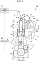
- An engine system 100 of this embodiment is mounted on, for example, a ship such as a large tanker and includes an engine 1, a turbocharger 200, a control unit 300 (a position acquisition device), and a position detector 400 (a detection device) as shown in FIG. 1 .
- the turbocharger 200 is regarded as an auxiliary machine and is described as a form separated from the engine 1 (a main machine).
- the turbocharger 200 can be configured as part of the engine 1.
- the turbocharger 200 is not an essential component for the engine system 100 of this embodiment and may not be provided in the engine system 100.
- FIG. 1 is a longitudinal cross-sectional view taken along the central axis of a cylinder liner 3a, which will be described later and is provided in the engine system 100.
- an installation side of an exhaust valve unit 5 to be described later may be referred to as an upper side
- an installation side of a crank shaft 11 to be described later may be referred to as a lower side.
- a diagram viewed in the central axis direction of the cylinder liner 3a may be referred to as a plan view.
- the engine 1 is a multi-cylinder uniflow scavenging diesel engine and is a dual fuel engine capable of performing a gas operation mode in which gas fuel such as natural gas is burned together with liquid fuel such as heavy oil and a diesel operation mode in which liquid fuel such as heavy oil is burned. In the gas operation mode, only gas fuel may be burned.
- the engine 1 includes a frame 2, a cylinder portion 3, a piston 4, the exhaust valve unit 5, a piston rod 6, a crosshead 7, a hydraulic unit 8 (a pressure-increasing mechanism), a connecting rod 9, a crank angle sensor 10, the crank shaft 11, a scavenging reservoir 12, an exhaust reservoir 13, and an air cooler 14. Further, a cylinder is constituted of the cylinder portion 3, the piston 4, the exhaust valve unit 5, and the piston rod 6.
- the frame 2 is a rigid member that supports the entire engine 1 and accommodates the crosshead 7, the hydraulic unit 8, and the connecting rod 9. Further, the frame 2 is configured such that a crosshead pin 7a (to be described later) of the crosshead 7 is movable in a reciprocating manner therein.
- the cylinder portion 3 includes the cylinder liner 3a, a cylinder head 3b, and a cylinder jacket 3c.
- the cylinder liner 3a is a cylindrical member and has a sliding surface with the piston 4 formed on the inside (the inner peripheral surface) thereof.
- a space surrounded by the inner peripheral surface of the cylinder liner 3a and the piston 4 constitutes a combustion chamber R1.
- a plurality of scavenging ports S are provided in a lower portion of the cylinder liner 3a.
- the scavenging ports S are openings arranged along the peripheral surface of the cylinder liner 3a and provide communication between a scavenging chamber R2 inside the cylinder jacket 3c and the inside of the cylinder liner 3a.
- the cylinder head 3b is a cover member that is provided in the upper end portion of the cylinder liner 3a.
- the center portion of the cylinder head 3b in a plan view is provided with an exhaust port H, which is connected to the exhaust reservoir 13.
- the exhaust port H communicates with the exhaust reservoir 13.
- the cylinder head 3b is provided with a fuel injection valve (not shown).
- a cylinder internal pressure sensor (not shown) is provided in the vicinity of the fuel injection valve of the cylinder head 3b. The cylinder internal pressure sensor detects a pressure inside the combustion chamber R1 and transmits the results to the control unit 300.
- the cylinder jacket 3c is a cylindrical member that is provided between the frame 2 and the cylinder liner 3a, in which the lower end portion of the cylinder liner 3a is inserted, and inside which the scavenging chamber R2 is formed. Further, the scavenging chamber R2 of the cylinder jacket 3c is connected to the scavenging reservoir 12.
- the piston 4 is formed in a substantially columnar shape, is connected to the piston rod 6 to be described later, and is disposed inside the cylinder liner 3a. Further, an outer peripheral surface of the piston 4 is provided with piston rings (not shown), and a gap between the piston 4 and the cylinder liner 3a is sealed by the piston rings.
- the piston 4 slides inside the cylinder liner 3a together with the piston rod 6 due to a change in pressure in the combustion chamber R1.
- the sliding direction of the piston 4 is the same as the central axis direction of the cylinder liner 3a (the up-down direction of FIG. 1 ).
- the exhaust valve unit 5 includes an exhaust valve 5a, an exhaust valve cage 5b, and an exhaust valve-driving unit 5c.
- the exhaust valve 5a is provided inside the cylinder head 3b and blocks the exhaust port H of the cylinder portion 3 by the exhaust valve-driving unit 5c.
- the exhaust valve cage 5b is a cylindrical casing that accommodates the end portion of the exhaust valve 5a.
- the exhaust valve-driving unit 5c is an actuator that moves the exhaust valve 5a in a direction parallel with the stroke direction (the sliding direction) of the piston 4.
- the piston rod 6 is an elongated member of which one end (upper end) is connected to the piston 4 and the other end (lower end) is connected to the crosshead pin 7a.
- the piston rod 6 of this embodiment is a bar-shaped member.
- the end portion (the lower end portion) of the piston rod 6 is inserted into the crosshead pin 7a and is connected to the connecting rod 9 such that the connecting rod 9 is rotatable.
- the piston rod 6 includes a rod-shaped main body 6a extending in the up-down direction and a large-diameter portion 6b formed by setting the diameter of part of the end portion of the piston rod 6 close to the crosshead pin 7a to be greater than that of the main body 6a (refer to FIG. 2 ).
- the large-diameter portion 6b is also formed in a columnar shape.
- the crosshead 7 includes the crosshead pin 7a, a guide shoe 7b, and a cover member 7c. Additionally, in FIG. 2 , an installation side of the piston rod 6 is the upper side, and an installation side of a plunger pump 8c or a relief valve 8f, which will be described later, is the lower side.
- the crosshead pin 7a is a columnar member that movably connects the piston rod 6 and the connecting rod 9, and a hydraulic chamber R3 (a fluid chamber), to and from which working oil (working fluid) is supplied and discharged, is provided in an insertion space (an insertion recess) of the crosshead pin 7a into which the end portion (the large-diameter portion 6b) of the piston rod 6 is inserted.
- the central axis of the crosshead pin 7a extends in a direction orthogonal to the sliding direction of the piston 4.
- the insertion recess is provided in the upper portion of the crosshead pin 7a to open upward.
- the outer peripheral surface of the large-diameter portion 6b liquid-tightly contacts an inner peripheral surface of the insertion recess.
- An outlet hole O is provided in a portion of the crosshead pin 7a below the center thereof and penetrates in the axial direction through the crosshead pin 7a.
- the outlet hole O is an opening from which cooling oil having passed through a cooling flow path (not shown) of the piston rod 6 is discharged.
- the crosshead pin 7a is provided with a supply flow path R4 that connects the hydraulic chamber R3 and the plunger pump 8c to be described later and a relief flow path R5 that connects the hydraulic chamber R3 and the relief valve 8f to be described later.
- the guide shoe 7b is a member that rotatably supports the crosshead pin 7a and moves on a guide rail (not shown) in the stroke direction of the piston 4 together with the crosshead pin 7a.
- the guide shoe 7b is provided inside the frame 2. Since the guide shoe 7b moves along the guide rail, the movement of the crosshead pin 7a in a direction other than a linear direction parallel with the stroke direction of the piston 4 is regulated. The rotational motion of the crosshead pin 7a around the central axis thereof is also regulated.
- the cover member 7c is an annular member that is fixed to the upper portion of the crosshead pin 7a and into which the end portion of the piston rod 6 is inserted.
- the cover member 7c is provided in the peripheral edge of the opening of the insertion recess of the crosshead pin 7a.
- the inner diameter of the cover member 7c is equal to the outer diameter of the main body 6a of the piston rod 6 and is less than the outer diameter of the large-diameter portion 6b.
- the large-diameter portion 6b is movable in the up-down direction inside the insertion recess.
- a space between the inner surface of the insertion recess and the lower surface of the large-diameter portion 6b constitutes the hydraulic chamber R3.
- the crosshead 7 having the above configuration transmits the linear motion of the piston 4 to the connecting rod 9.
- the hydraulic unit 8 includes a supply pump 8a, a swing pipe 8b, the plunger pump 8c, a first check valve 8d and a second check valve 8e connected to the plunger pump 8c, and the relief valve 8f. Further, the piston rod 6, the crosshead 7, and the hydraulic unit 8 function as a variable compression device of the present disclosure.
- the supply pump 8a is a pump that, based on instructions from the control unit 300, pressurizes working oil supplied from a working oil tank (not shown) and supplies the working oil to the plunger pump 8c.
- the supply pump 8a is driven by the electric power of a battery of the ship and can operate before the liquid fuel is supplied to the combustion chamber R1.
- the swing pipe 8b is a pipe that connects the supply pump 8a to the plunger pump 8c of each cylinder and is swingable between the plunger pump 8c moving together with the crosshead pin 7a and the fixed supply pump 8a.
- the plunger pump 8c is fixed to the crosshead pin 7a and includes a bar-shaped plunger 8c1, a cylinder 8c2 that accommodates the plunger 8c1 such that the plunger 8c1 is slidable therein, and a plunger-driving unit 8c3.
- the plunger 8c1 is connected to the plunger-driving unit 8c3, thereby slides inside the cylinder 8c2, pressurizes working oil and supplies the working oil to the hydraulic chamber R3.
- a working oil discharge-side opening provided in an end portion of the cylinder 8c2 is provided with the first check valve 8d
- a working oil suction-side opening provided on a side peripheral surface of the cylinder 8c2 is provided with the second check valve 8e.
- the plunger-driving unit 8c3 is connected to the plunger 8c1 and moves the plunger 8c1 in a reciprocating manner based on instructions from the control unit 300.
- the first check valve 8d is configured to be closed when a valve body is pushed inward of the cylinder 8c2 by a pushing member (not shown) and prevents the working oil supplied to the hydraulic chamber R3 from reversely flowing toward the cylinder 8c2. Further, the first check valve 8d is opened by the valve body being pushed by the working oil when the pressure of the working oil inside the cylinder 8c2 becomes equal to or higher than the pushing force (the valve-opening pressure) of the pushing member of the first check valve 8d.
- the second check valve 8e is pushed outward of the cylinder 8c2 by a pushing member (not shown) and prevents the working oil supplied to the cylinder 8c2 from reversely flowing toward the supply pump 8a.
- the second check valve 8e is opened by the valve body being pushed by the working oil when the pressure of the working oil supplied from the supply pump 8a becomes equal to or higher than the pushing force (the valve-opening pressure) of the pushing member of the second check valve 8e. Additionally, the valve-opening pressure of the first check valve 8d is higher than that of the second check valve 8e, and the first check valve 8d is not opened by the pressure of the working oil supplied from the supply pump 8a during a normal operation in which the operation is performed at a predetermined compression ratio.
- the relief valve 8f is provided in the crosshead pin 7a and includes a main body 8f1 and a relief valve-driving unit 8f2.
- the main body 8f1 is a valve that is connected to the working oil tank (not shown) and the hydraulic chamber R3 through the relief flow path R5.
- the relief valve-driving unit 8f2 is connected to the valve body of the main body 8f1 and opens and closes the main body 8f1 based on instructions from the control unit 300. When the relief valve 8f is opened by the relief valve-driving unit 8f2, the working oil stored in the hydraulic chamber R3 is returned to the working oil tank.
- the connecting rod 9 is an elongated member that is connected to the crosshead pin 7a and is connected to the crank shaft 11.
- the connecting rod 9 converts the linear motion of the piston 4 transmitted to the crosshead pin 7a into rotational motion.
- the crank angle sensor 10 is a sensor for measuring a crank angle of the crank shaft 11 and transmits a crank pulse signal for calculating the crank angle to the control unit 300.
- the crank shaft 11 is an elongated member that is connected to the connecting rod 9 provided in the cylinder and is rotated by the rotational motion transmitted by each connecting rod 9 so as to transmit motive power to, for example, a screw or the like.
- the scavenging reservoir 12 is provided between the cylinder jacket 3c and the turbocharger 200, and air pressurized by the turbocharger 200 flows into the scavenging reservoir 12.
- the air cooler 14 is provided inside the scavenging reservoir 12.
- the exhaust reservoir 13 is a tubular member that is connected to the exhaust port H of each cylinder and is connected to the turbocharger 200. A gas discharged from the exhaust port H is temporarily stored in the exhaust reservoir 13 and is supplied to the turbocharger 200 while its pulsation is limited.
- the air cooler 14 is a device that cools air inside the scavenging reservoir 12.
- the turbocharger 200 is a device that pressurizes air sucked from an intake port (not shown) by a turbine rotated by a gas discharged from the exhaust port H and supplies the air to the combustion chamber R1 through the scavenging reservoir 12, the air cooler 14, and the scavenging chamber R2.
- the control unit 300 is a computer that controls a fuel supply amount or the like based on an operation or the like of an operator of the ship.
- the control unit 300 includes a CPU (Central Processing Unit), a memory such as a RAM (Random Access Memory) or a ROM (Read Only Memory), and a storage device such as a SSD (Solid State Drive) or a HDD (Hard Disk Drive).
- the control unit 300 is connected to the position detector 400 by a wire. Additionally, the control unit 300 may be configured to perform wireless communication of information with the position detector 400. Further, the control unit 300 changes the compression ratio of the combustion chamber R1 by controlling the hydraulic unit 8.
- control unit 300 acquires the positional information of the piston rod 6 based on a signal from the position detector 400, controls the plunger pump 8c, the supply pump 8a, and the relief valve 8f, and adjusts the amount of the working oil in the hydraulic chamber R3, thereby changing the position (the position in the sliding direction) of the piston rod 6 and changing the compression ratio.
- control unit 300 of this embodiment has the function of the position acquisition device of the present disclosure as well as the function of controlling the operation of the engine 1 by, for example, adjusting fuel to be supplied to the engine 1.
- a control device corresponding to the position acquisition device of the present disclosure other than the control unit 300 may be provided.
- the position detector 400 includes a detection target 410 and a detector 420.
- the detection target 410 includes two uneven portions 411 and 412.
- the uneven portions 411 and 412 are provided on a lower end side of the sliding surface of the piston 4 and each of them includes a plurality of recesses and protrusions formed at equal intervals in the sliding direction of the piston 4. That is, the widths in the sliding direction of the recesses and the protrusions constituting the uneven portions 411 and 412 are all equal. Further, the uneven portions 411 and 412 are provided adjacently in the circumferential direction of the piston.
- the uneven portions 411 and 412 are provided such that uneven portions equal to each other are arranged and the positions of the uneven portions are shifted by half the width of each recess in the sliding direction of the piston 4.
- the shift amount of the positions of the uneven portions is not limited to half the width of each recess but may be set arbitrarily according to the resolution of the detector.
- the detection target 410 is provided on a lower side (the side close to the piston rod 6) of the piston rings (not shown) provided in the piston 4. Accordingly, the detection target 410 is less affected by lubricating oil on the sliding surface of the piston 4.
- the detector 420 is provided on a lower end side of the inner peripheral surface of the cylinder liner 3a, which is a position farther than the scavenging port S with respect to the combustion chamber R1, and at the same position as or on the outside of the cylinder liner wall surface.
- the detector is embedded in and fixed to the lower end side of the inner peripheral surface of the cylinder liner 3a.
- the inner surface of the position detector 400 in the radial direction of the cylinder liner 3a may be provided so as to be flush with the inner peripheral surface of the cylinder liner 3a.
- the detector 420 is a sensor that generates an electric signal (a signal including positional information of the piston rod 6 (piston 4)) in accordance with a change in distance from the surface of the detection target 410 as two detection targets 410 move.
- the detector 420 includes, for example, photoelectric sensors, laser sensors, and proximity sensors such as inductive and capacitance sensors. Accordingly, the detector 420 can detect which one of the recesses and the protrusions of the uneven portions 411 and 412 faces the detector and thus detect the position of the piston 4 in the sliding direction.
- the engine system 100 having the above configuration is a device that ignites and explodes fuel injected into the combustion chamber R1 from the fuel injection valve (not shown), thereby slides the piston 4 inside the cylinder liner 3a and rotates the crank shaft 11.
- fuel supplied to the combustion chamber R1 is mixed with air having flowed thereinto from the scavenging port S, thereafter is compressed by the piston 4 moving toward the top dead center, and spontaneously ignites when the temperature thereof rises. Further, in a case of liquid fuel, the fuel is vaporized and spontaneously ignites when the temperature rises in the combustion chamber R1.
- the fuel in the combustion chamber R1 spontaneously ignites and suddenly expands so that a pressure is applied to the piston 4 toward the bottom dead center. Accordingly, the piston 4 moves toward the bottom dead center so that the piston rod 6 is moved together with the piston 4 and the crank shaft 11 is rotated through the connecting rod 9. Further, when the piston 4 is moved to the bottom dead center, pressurized air flows from the scavenging port S into the combustion chamber R1. At this time, the exhaust port H is opened by the exhaust valve unit 5 operating, and the exhaust gas inside the combustion chamber R1 is pushed out to the exhaust reservoir 13 by the pressurized air.
- the supply pump 8a is driven by the control unit 300 and working oil is supplied to the plunger pump 8c.
- the control unit 300 drives the plunger pump 8c so as to pressurize the working oil up to a pressure that can lift the piston rod 6 and supplies the working oil to the hydraulic chamber R3.
- the end portion (the large-diameter portion 6b) of the piston rod 6 is lifted by the pressure of the working oil in the hydraulic chamber R3 and the top dead center position of the piston 4 is shifted upward (toward the exhaust port H) with this lift.
- the relief valve 8f is driven by the control unit 300 so that the hydraulic chamber R3 communicates with the working oil tank (not shown). Then, the weight of the piston rod 6 is applied to the working oil in the hydraulic chamber R3 so that the working oil in the hydraulic chamber R3 is pushed out to the working oil tank through the relief valve 8f. Accordingly, the amount of the working oil in the hydraulic chamber R3 decreases, the piston rod 6 is moved downward
- the recesses and protrusions of the detection target 410 are relatively moved so that the distance from the detection target 410 detected by the detector 420 changes.
- the detector 420 outputs a change in the recesses and protrusions, that is, a change in the relative distance from the surface of the detection target 410, as an electric signal to the control unit 300.
- the position detection resolution of the detector 420 has a length corresponding to half the width of each of the recesses and protrusions in the sliding direction of the piston 4.
- the control unit 300 receives an electric signal of the detector 420 and calculates (acquires) the position of the piston 4 based on the electric signal. Then, the control unit 300 adjusts the position of the piston rod 6 by controlling the hydraulic unit 8 based on the position of the piston 4.
- the position detector 400 outputs a signal including positional information of the piston 4 in the movement direction
- the control unit 300 acquires the positional information of the piston 4. Accordingly, the control unit 300 can accurately adjust the position of the piston 4 in the movement direction by constantly monitoring whether the position of the piston 4 in the movement direction matches a target position of the piston 4. Further, the control unit 300 can more stably control the variable compression device by accurately acquiring the position of the piston 4.
- the detector 420 is embedded in the cylinder liner 3a that does not move relative to the frame 2. Accordingly, the detector 420 and the control unit 300 can be connected to each other by wire. Thus, it is not necessary to provide a wireless transmission device such as a telemeter, and the installation operation is easy.
- two detection targets 410 are provided so as to be shifted by a half wavelength in the sliding direction of the piston 4. Since a plurality of detection targets 410 are provided, the detector 420 can reliably detect the detection target 410. Further, since it is possible to detect the position of the piston 4 with the minimum resolution corresponding to the length of half the width of recess or protrusion in the sliding direction of the piston 4, the position of the piston 4 can be more accurately detected.
- the detector 420 is provided at a position farther than the scavenging port S with respect to the combustion chamber R1. Accordingly, the influence of heat and pressure in the combustion chamber R1 on the detector 420 can be reduced.
- a modification of the first embodiment will be described as a second embodiment. Additionally, the same components as those of the first embodiment will be represented by the same reference signs, and descriptions thereof will be omitted.
- An engine system 100 of this embodiment does not include the position detector 400.
- a control unit 300 acquires the position of the piston 4 by calculating an actual compression ratio based on the internal pressure of the combustion chamber R1 calculated from a signal from a cylinder internal pressure sensor (a detection device, not shown).
- the control unit 300 calculates the compression ratio of the cylinder portion 3 based on Expression 1 above from a signal input from the cylinder internal pressure sensor. Further, the control unit 300 calculates the position of the piston 4 from the calculated compression ratio.
- the position of the piston 4 is acquired based on the cylinder internal pressure. Accordingly, the control unit 300 can accurately adjust the position of the piston 4 in the movement direction by constantly monitoring whether the position of the piston 4 in the movement direction matches a target position of the piston 4. Further, the control unit 300 can more stably control the variable compression device by accurately acquiring the position of the piston 4.
- the engine system 100 includes: a variable compression device (the piston rod 6, the crosshead 7, and the hydraulic unit 8) including the hydraulic chamber R3 (a fluid chamber) in which the piston rod 6 connected to the piston 4 is moved in a direction to increase the compression ratio by pressurized working oil (working fluid) being supplied thereto; the position detector 400 (a detection device) that outputs a signal including positional information of the piston 4; and the control unit 300 (a position acquisition device) that acquires the position of the piston 4 based on the signal.
- a variable compression device the piston rod 6, the crosshead 7, and the hydraulic unit 8
- the hydraulic chamber R3 a fluid chamber
- the position detector 400 a detection device
- the control unit 300 a position acquisition device
- At least part (a cylinder internal pressure sensor, not shown) of the position detector 400 is provided in the cylinder liner 3a inside which the piston 4 slides, and the position detector 400 is configured to detect the position in the sliding direction of the piston 4.
- the position detector 400 includes the detection target 410 provided in the piston 4 and the detector 420 provided in the cylinder liner 3a.
- the position detector 400 includes a plurality of position detectors provided on a sliding surface of the piston 4 in the circumferential direction.
- the detector 420 is provided at a position farther than the scavenging port S of the cylinder liner 3a with respect to the combustion chamber R1 in the sliding direction of the piston 4. In other words, the detector 420 is provided such that the scavenging port S of the cylinder liner 3a is positioned between the detector 420 and the combustion chamber R1 in the sliding direction of the piston 4.
- the position detector 400 acquires the position of the piston 4 by detecting the recesses and protrusions, but the present disclosure is not limited thereto.
- the position detector 400 may include a detection target 410 in which magnetic members are arranged at equal intervals in the sliding direction of the piston 4 and a detector 420 (magnetic sensor) that detects a change in the magnetic field.
- the detector 420 of the position detector 400 is a sensor (a proximity sensor or the like) capable of detecting the lower end or the like of the piston 4, only the detector 420 (part of the position detector 400) may be provided in the cylinder liner 3a.
- the installation area, the position, and the number of the detection target 410 are not limited to the above-described embodiments.
- the detection target 410 may be provided at each of three or more positions or only one position.
- a plurality of detectors 420 may be provided, and a plurality of detection targets 410 may be provided at positions facing each other (the positions facing each other in a radial direction of the cylinder liner 3a) between which the center of the piston 4 (the center of the piston 4 in the radial direction) is disposed.
- the inclination of the piston 4 with respect to the sliding direction can also be detected by increasing the position detection resolution of the detection target 410 and the detector 420.
- the present disclosure can be used for an engine system with a variable compression device including a fluid chamber in which a piston rod connected to a piston is moved in a direction to increase a compression ratio by a pressurized working fluid being supplied thereto.
Abstract
Description
- The present disclosure relates to an engine system.
- Priority is claimed on Japanese Patent Application No.
2017-207964 filed on October 27, 2017 - For example,
Patent Document 1 discloses a large reciprocating piston combustion engine having a crosshead. The large reciprocating piston combustion engine ofPatent Document 1 is a dual fuel engine capable of operating on both a liquid fuel such as heavy oil and a gas fuel such as natural gas. In the large reciprocating piston combustion engine ofPatent Document 1, in order to correspond to both a compression ratio suitable for operation with liquid fuel and a compression ratio suitable for operation with gas fuel, a crosshead portion is provided with an adjustment mechanism for changing the compression ratio by moving a piston rod using hydraulic pressure. - [Patent Document 1] Japanese Unexamined Patent Application, First Publication No.
2014-20375 - The above-described engine system with a compression adjustment device that changes the compression ratio changes the position of the piston rod in the movement direction thereof, thereby changing the bottom dead center position and the top dead center position of the piston and adjusting the compression ratio. Such an adjustment of the compression ratio is performed by a control device of the engine system based on an operation of an operator or the like. However, in some cases, the control device cannot acquire the position of the piston rod, and it may be difficult to accurately adjust the compression ratio.
- The present disclosure is made in view of the above-described problems and an object thereof is to accurately acquire the compression ratio in an engine system with a variable compression device.
- An engine system of a first aspect of the present disclosure includes: a variable compression device including a fluid chamber in which a piston rod connected to a piston is moved in a direction to increase a compression ratio by a pressurized working fluid being supplied thereto; a detection device that outputs a signal including positional information of the piston; and a position acquisition device that acquires a position of the piston based on the signal.
- A second aspect of the present disclosure is that in the first aspect, at least part of the detection device is provided in a cylinder liner inside which the piston slides, and the detection device is configured to detect a position in a sliding direction of the piston.
- A third aspect of the present disclosure is that in the second aspect, the detection device includes a detection target provided in the piston and a detector provided in the cylinder liner.
- A fourth aspect of the present disclosure is that in the third aspect, the detection target includes a plurality of detection targets provided on a sliding surface of the piston in a circumferential direction.
- A fifth aspect of the present disclosure is that in the third or fourth aspect, the detector is provided at a position farther than a scavenging port of the cylinder liner with respect to a combustion chamber in the sliding direction of the piston.
- According to the present disclosure, the detection device outputs a signal including the positional information in the movement direction (the sliding direction) of the piston, the position acquisition device acquires the positional information of the piston, and a control unit provided in the engine system controls, based on the positional information, a pressure-increasing mechanism that adjusts the pressure in the fluid chamber. Accordingly, the control unit can acquire the accurate position of the piston in the movement direction and constantly monitor whether the position matches a target position of the piston. Further, since the control unit accurately acquires the position of the piston, the control unit can more stably control the variable compression device.
-
-
FIG. 1 is a cross-sectional view of an engine system of an embodiment of the present disclosure. -
FIG. 2 is a schematic cross-sectional view showing part of the engine system of the embodiment of the present disclosure. -
FIG. 3 is an enlarged schematic cross-sectional view showing part of the engine system of the embodiment of the present disclosure. - Hereinafter, embodiments of an
engine system 100 of the present disclosure will be described with reference to the drawings. - An
engine system 100 of this embodiment is mounted on, for example, a ship such as a large tanker and includes anengine 1, aturbocharger 200, a control unit 300 (a position acquisition device), and a position detector 400 (a detection device) as shown inFIG. 1 . Additionally, in this embodiment, theturbocharger 200 is regarded as an auxiliary machine and is described as a form separated from the engine 1 (a main machine). However, theturbocharger 200 can be configured as part of theengine 1. Additionally, theturbocharger 200 is not an essential component for theengine system 100 of this embodiment and may not be provided in theengine system 100. -
FIG. 1 is a longitudinal cross-sectional view taken along the central axis of acylinder liner 3a, which will be described later and is provided in theengine system 100. InFIG. 1 , an installation side of anexhaust valve unit 5 to be described later may be referred to as an upper side, and an installation side of acrank shaft 11 to be described later may be referred to as a lower side. A diagram viewed in the central axis direction of thecylinder liner 3a may be referred to as a plan view. - The
engine 1 is a multi-cylinder uniflow scavenging diesel engine and is a dual fuel engine capable of performing a gas operation mode in which gas fuel such as natural gas is burned together with liquid fuel such as heavy oil and a diesel operation mode in which liquid fuel such as heavy oil is burned. In the gas operation mode, only gas fuel may be burned. Theengine 1 includes aframe 2, acylinder portion 3, apiston 4, theexhaust valve unit 5, apiston rod 6, acrosshead 7, a hydraulic unit 8 (a pressure-increasing mechanism), a connecting rod 9, acrank angle sensor 10, thecrank shaft 11, ascavenging reservoir 12, anexhaust reservoir 13, and anair cooler 14. Further, a cylinder is constituted of thecylinder portion 3, thepiston 4, theexhaust valve unit 5, and thepiston rod 6. - The
frame 2 is a rigid member that supports theentire engine 1 and accommodates thecrosshead 7, thehydraulic unit 8, and the connecting rod 9. Further, theframe 2 is configured such that acrosshead pin 7a (to be described later) of thecrosshead 7 is movable in a reciprocating manner therein. - The
cylinder portion 3 includes thecylinder liner 3a, acylinder head 3b, and acylinder jacket 3c. Thecylinder liner 3a is a cylindrical member and has a sliding surface with thepiston 4 formed on the inside (the inner peripheral surface) thereof. A space surrounded by the inner peripheral surface of thecylinder liner 3a and thepiston 4 constitutes a combustion chamber R1. Further, a plurality of scavenging ports S are provided in a lower portion of thecylinder liner 3a. The scavenging ports S are openings arranged along the peripheral surface of thecylinder liner 3a and provide communication between a scavenging chamber R2 inside thecylinder jacket 3c and the inside of thecylinder liner 3a. Thecylinder head 3b is a cover member that is provided in the upper end portion of thecylinder liner 3a. The center portion of thecylinder head 3b in a plan view is provided with an exhaust port H, which is connected to theexhaust reservoir 13. The exhaust port H communicates with theexhaust reservoir 13. Further, thecylinder head 3b is provided with a fuel injection valve (not shown). Furthermore, a cylinder internal pressure sensor (not shown) is provided in the vicinity of the fuel injection valve of thecylinder head 3b. The cylinder internal pressure sensor detects a pressure inside the combustion chamber R1 and transmits the results to thecontrol unit 300. Thecylinder jacket 3c is a cylindrical member that is provided between theframe 2 and thecylinder liner 3a, in which the lower end portion of thecylinder liner 3a is inserted, and inside which the scavenging chamber R2 is formed. Further, the scavenging chamber R2 of thecylinder jacket 3c is connected to thescavenging reservoir 12. - The
piston 4 is formed in a substantially columnar shape, is connected to thepiston rod 6 to be described later, and is disposed inside thecylinder liner 3a. Further, an outer peripheral surface of thepiston 4 is provided with piston rings (not shown), and a gap between thepiston 4 and thecylinder liner 3a is sealed by the piston rings. Thepiston 4 slides inside thecylinder liner 3a together with thepiston rod 6 due to a change in pressure in the combustion chamber R1. The sliding direction of thepiston 4 is the same as the central axis direction of thecylinder liner 3a (the up-down direction ofFIG. 1 ). - The
exhaust valve unit 5 includes anexhaust valve 5a, anexhaust valve cage 5b, and an exhaust valve-drivingunit 5c. Theexhaust valve 5a is provided inside thecylinder head 3b and blocks the exhaust port H of thecylinder portion 3 by the exhaust valve-drivingunit 5c. Theexhaust valve cage 5b is a cylindrical casing that accommodates the end portion of theexhaust valve 5a. The exhaust valve-drivingunit 5c is an actuator that moves theexhaust valve 5a in a direction parallel with the stroke direction (the sliding direction) of thepiston 4. - The
piston rod 6 is an elongated member of which one end (upper end) is connected to thepiston 4 and the other end (lower end) is connected to thecrosshead pin 7a. Thepiston rod 6 of this embodiment is a bar-shaped member. The end portion (the lower end portion) of thepiston rod 6 is inserted into thecrosshead pin 7a and is connected to the connecting rod 9 such that the connecting rod 9 is rotatable. Further, thepiston rod 6 includes a rod-shapedmain body 6a extending in the up-down direction and a large-diameter portion 6b formed by setting the diameter of part of the end portion of thepiston rod 6 close to thecrosshead pin 7a to be greater than that of themain body 6a (refer toFIG. 2 ). The large-diameter portion 6b is also formed in a columnar shape. - As shown in
FIGS. 1 and2 , thecrosshead 7 includes thecrosshead pin 7a, aguide shoe 7b, and acover member 7c. Additionally, inFIG. 2 , an installation side of thepiston rod 6 is the upper side, and an installation side of aplunger pump 8c or arelief valve 8f, which will be described later, is the lower side. Thecrosshead pin 7a is a columnar member that movably connects thepiston rod 6 and the connecting rod 9, and a hydraulic chamber R3 (a fluid chamber), to and from which working oil (working fluid) is supplied and discharged, is provided in an insertion space (an insertion recess) of thecrosshead pin 7a into which the end portion (the large-diameter portion 6b) of thepiston rod 6 is inserted. The central axis of thecrosshead pin 7a extends in a direction orthogonal to the sliding direction of thepiston 4. The insertion recess is provided in the upper portion of thecrosshead pin 7a to open upward. The outer peripheral surface of the large-diameter portion 6b liquid-tightly contacts an inner peripheral surface of the insertion recess. An outlet hole O is provided in a portion of thecrosshead pin 7a below the center thereof and penetrates in the axial direction through thecrosshead pin 7a. The outlet hole O is an opening from which cooling oil having passed through a cooling flow path (not shown) of thepiston rod 6 is discharged. Further, thecrosshead pin 7a is provided with a supply flow path R4 that connects the hydraulic chamber R3 and theplunger pump 8c to be described later and a relief flow path R5 that connects the hydraulic chamber R3 and therelief valve 8f to be described later. - The
guide shoe 7b is a member that rotatably supports thecrosshead pin 7a and moves on a guide rail (not shown) in the stroke direction of thepiston 4 together with thecrosshead pin 7a. Theguide shoe 7b is provided inside theframe 2. Since theguide shoe 7b moves along the guide rail, the movement of thecrosshead pin 7a in a direction other than a linear direction parallel with the stroke direction of thepiston 4 is regulated. The rotational motion of thecrosshead pin 7a around the central axis thereof is also regulated. Thecover member 7c is an annular member that is fixed to the upper portion of thecrosshead pin 7a and into which the end portion of thepiston rod 6 is inserted. Thecover member 7c is provided in the peripheral edge of the opening of the insertion recess of thecrosshead pin 7a. The inner diameter of thecover member 7c is equal to the outer diameter of themain body 6a of thepiston rod 6 and is less than the outer diameter of the large-diameter portion 6b. The large-diameter portion 6b is movable in the up-down direction inside the insertion recess. A space between the inner surface of the insertion recess and the lower surface of the large-diameter portion 6b constitutes the hydraulic chamber R3. Thecrosshead 7 having the above configuration transmits the linear motion of thepiston 4 to the connecting rod 9. - As shown in
FIG. 2 , thehydraulic unit 8 includes asupply pump 8a, aswing pipe 8b, theplunger pump 8c, afirst check valve 8d and asecond check valve 8e connected to theplunger pump 8c, and therelief valve 8f. Further, thepiston rod 6, thecrosshead 7, and thehydraulic unit 8 function as a variable compression device of the present disclosure. - The
supply pump 8a is a pump that, based on instructions from thecontrol unit 300, pressurizes working oil supplied from a working oil tank (not shown) and supplies the working oil to theplunger pump 8c. Thesupply pump 8a is driven by the electric power of a battery of the ship and can operate before the liquid fuel is supplied to the combustion chamber R1. Theswing pipe 8b is a pipe that connects thesupply pump 8a to theplunger pump 8c of each cylinder and is swingable between theplunger pump 8c moving together with thecrosshead pin 7a and the fixedsupply pump 8a. - The
plunger pump 8c is fixed to thecrosshead pin 7a and includes a bar-shaped plunger 8c1, a cylinder 8c2 that accommodates the plunger 8c1 such that the plunger 8c1 is slidable therein, and a plunger-driving unit 8c3. In theplunger pump 8c, the plunger 8c1 is connected to the plunger-driving unit 8c3, thereby slides inside the cylinder 8c2, pressurizes working oil and supplies the working oil to the hydraulic chamber R3. Further, a working oil discharge-side opening provided in an end portion of the cylinder 8c2 is provided with thefirst check valve 8d, and a working oil suction-side opening provided on a side peripheral surface of the cylinder 8c2 is provided with thesecond check valve 8e. The plunger-driving unit 8c3 is connected to the plunger 8c1 and moves the plunger 8c1 in a reciprocating manner based on instructions from thecontrol unit 300. - The
first check valve 8d is configured to be closed when a valve body is pushed inward of the cylinder 8c2 by a pushing member (not shown) and prevents the working oil supplied to the hydraulic chamber R3 from reversely flowing toward the cylinder 8c2. Further, thefirst check valve 8d is opened by the valve body being pushed by the working oil when the pressure of the working oil inside the cylinder 8c2 becomes equal to or higher than the pushing force (the valve-opening pressure) of the pushing member of thefirst check valve 8d. Thesecond check valve 8e is pushed outward of the cylinder 8c2 by a pushing member (not shown) and prevents the working oil supplied to the cylinder 8c2 from reversely flowing toward thesupply pump 8a. Further, thesecond check valve 8e is opened by the valve body being pushed by the working oil when the pressure of the working oil supplied from thesupply pump 8a becomes equal to or higher than the pushing force (the valve-opening pressure) of the pushing member of thesecond check valve 8e. Additionally, the valve-opening pressure of thefirst check valve 8d is higher than that of thesecond check valve 8e, and thefirst check valve 8d is not opened by the pressure of the working oil supplied from thesupply pump 8a during a normal operation in which the operation is performed at a predetermined compression ratio. - The
relief valve 8f is provided in thecrosshead pin 7a and includes a main body 8f1 and a relief valve-driving unit 8f2. The main body 8f1 is a valve that is connected to the working oil tank (not shown) and the hydraulic chamber R3 through the relief flow path R5. The relief valve-driving unit 8f2 is connected to the valve body of the main body 8f1 and opens and closes the main body 8f1 based on instructions from thecontrol unit 300. When therelief valve 8f is opened by the relief valve-driving unit 8f2, the working oil stored in the hydraulic chamber R3 is returned to the working oil tank. - As shown in
FIG. 1 , the connecting rod 9 is an elongated member that is connected to thecrosshead pin 7a and is connected to thecrank shaft 11. The connecting rod 9 converts the linear motion of thepiston 4 transmitted to thecrosshead pin 7a into rotational motion. Thecrank angle sensor 10 is a sensor for measuring a crank angle of thecrank shaft 11 and transmits a crank pulse signal for calculating the crank angle to thecontrol unit 300. - The
crank shaft 11 is an elongated member that is connected to the connecting rod 9 provided in the cylinder and is rotated by the rotational motion transmitted by each connecting rod 9 so as to transmit motive power to, for example, a screw or the like. The scavengingreservoir 12 is provided between thecylinder jacket 3c and theturbocharger 200, and air pressurized by theturbocharger 200 flows into the scavengingreservoir 12. Further, theair cooler 14 is provided inside the scavengingreservoir 12. Theexhaust reservoir 13 is a tubular member that is connected to the exhaust port H of each cylinder and is connected to theturbocharger 200. A gas discharged from the exhaust port H is temporarily stored in theexhaust reservoir 13 and is supplied to theturbocharger 200 while its pulsation is limited. Theair cooler 14 is a device that cools air inside the scavengingreservoir 12. - The
turbocharger 200 is a device that pressurizes air sucked from an intake port (not shown) by a turbine rotated by a gas discharged from the exhaust port H and supplies the air to the combustion chamber R1 through the scavengingreservoir 12, theair cooler 14, and the scavenging chamber R2. - The
control unit 300 is a computer that controls a fuel supply amount or the like based on an operation or the like of an operator of the ship. Thecontrol unit 300 includes a CPU (Central Processing Unit), a memory such as a RAM (Random Access Memory) or a ROM (Read Only Memory), and a storage device such as a SSD (Solid State Drive) or a HDD (Hard Disk Drive). Thecontrol unit 300 is connected to theposition detector 400 by a wire. Additionally, thecontrol unit 300 may be configured to perform wireless communication of information with theposition detector 400. Further, thecontrol unit 300 changes the compression ratio of the combustion chamber R1 by controlling thehydraulic unit 8. Specifically, thecontrol unit 300 acquires the positional information of thepiston rod 6 based on a signal from theposition detector 400, controls theplunger pump 8c, thesupply pump 8a, and therelief valve 8f, and adjusts the amount of the working oil in the hydraulic chamber R3, thereby changing the position (the position in the sliding direction) of thepiston rod 6 and changing the compression ratio. - Additionally, the
control unit 300 of this embodiment has the function of the position acquisition device of the present disclosure as well as the function of controlling the operation of theengine 1 by, for example, adjusting fuel to be supplied to theengine 1. However, a control device corresponding to the position acquisition device of the present disclosure other than thecontrol unit 300 may be provided. - As shown in
FIGS. 1 and3 , theposition detector 400 includes adetection target 410 and adetector 420. Thedetection target 410 includes twouneven portions uneven portions piston 4 and each of them includes a plurality of recesses and protrusions formed at equal intervals in the sliding direction of thepiston 4. That is, the widths in the sliding direction of the recesses and the protrusions constituting theuneven portions uneven portions uneven portions piston 4. The shift amount of the positions of the uneven portions is not limited to half the width of each recess but may be set arbitrarily according to the resolution of the detector. Additionally, thedetection target 410 is provided on a lower side (the side close to the piston rod 6) of the piston rings (not shown) provided in thepiston 4. Accordingly, thedetection target 410 is less affected by lubricating oil on the sliding surface of thepiston 4. - The
detector 420 is provided on a lower end side of the inner peripheral surface of thecylinder liner 3a, which is a position farther than the scavenging port S with respect to the combustion chamber R1, and at the same position as or on the outside of the cylinder liner wall surface. In this embodiment, the detector is embedded in and fixed to the lower end side of the inner peripheral surface of thecylinder liner 3a. The inner surface of theposition detector 400 in the radial direction of thecylinder liner 3a may be provided so as to be flush with the inner peripheral surface of thecylinder liner 3a. Thedetector 420 is a sensor that generates an electric signal (a signal including positional information of the piston rod 6 (piston 4)) in accordance with a change in distance from the surface of thedetection target 410 as twodetection targets 410 move. Thedetector 420 includes, for example, photoelectric sensors, laser sensors, and proximity sensors such as inductive and capacitance sensors. Accordingly, thedetector 420 can detect which one of the recesses and the protrusions of theuneven portions piston 4 in the sliding direction. - The
engine system 100 having the above configuration is a device that ignites and explodes fuel injected into the combustion chamber R1 from the fuel injection valve (not shown), thereby slides thepiston 4 inside thecylinder liner 3a and rotates thecrank shaft 11. In detail, fuel supplied to the combustion chamber R1 is mixed with air having flowed thereinto from the scavenging port S, thereafter is compressed by thepiston 4 moving toward the top dead center, and spontaneously ignites when the temperature thereof rises. Further, in a case of liquid fuel, the fuel is vaporized and spontaneously ignites when the temperature rises in the combustion chamber R1. - Then, the fuel in the combustion chamber R1 spontaneously ignites and suddenly expands so that a pressure is applied to the
piston 4 toward the bottom dead center. Accordingly, thepiston 4 moves toward the bottom dead center so that thepiston rod 6 is moved together with thepiston 4 and thecrank shaft 11 is rotated through the connecting rod 9. Further, when thepiston 4 is moved to the bottom dead center, pressurized air flows from the scavenging port S into the combustion chamber R1. At this time, the exhaust port H is opened by theexhaust valve unit 5 operating, and the exhaust gas inside the combustion chamber R1 is pushed out to theexhaust reservoir 13 by the pressurized air. - In a case where the compression ratio is increased, the
supply pump 8a is driven by thecontrol unit 300 and working oil is supplied to theplunger pump 8c. Then, thecontrol unit 300 drives theplunger pump 8c so as to pressurize the working oil up to a pressure that can lift thepiston rod 6 and supplies the working oil to the hydraulic chamber R3. The end portion (the large-diameter portion 6b) of thepiston rod 6 is lifted by the pressure of the working oil in the hydraulic chamber R3 and the top dead center position of thepiston 4 is shifted upward (toward the exhaust port H) with this lift. - In a case where the compression ratio is decreased, the
relief valve 8f is driven by thecontrol unit 300 so that the hydraulic chamber R3 communicates with the working oil tank (not shown). Then, the weight of thepiston rod 6 is applied to the working oil in the hydraulic chamber R3 so that the working oil in the hydraulic chamber R3 is pushed out to the working oil tank through therelief valve 8f. Accordingly, the amount of the working oil in the hydraulic chamber R3 decreases, thepiston rod 6 is moved downward - (toward the crank shaft 11), and the top dead center position of the
piston 4 is shifted downward with this movement. - Next, a method of adjusting the position of the
piston rod 6 of this embodiment will be described. - When the
piston 4 is moved with the movement of thepiston rod 6, the recesses and protrusions of thedetection target 410 are relatively moved so that the distance from thedetection target 410 detected by thedetector 420 changes. Thedetector 420 outputs a change in the recesses and protrusions, that is, a change in the relative distance from the surface of thedetection target 410, as an electric signal to thecontrol unit 300. Additionally, since twodetection targets 410 are arranged so as to be shifted by half the width of each recess and the magnetic field of eachdetection target 410 is detected, the position detection resolution of thedetector 420 has a length corresponding to half the width of each of the recesses and protrusions in the sliding direction of thepiston 4. - The
control unit 300 receives an electric signal of thedetector 420 and calculates (acquires) the position of thepiston 4 based on the electric signal. Then, thecontrol unit 300 adjusts the position of thepiston rod 6 by controlling thehydraulic unit 8 based on the position of thepiston 4. - According to the
engine system 100 of this embodiment, theposition detector 400 outputs a signal including positional information of thepiston 4 in the movement direction, and thecontrol unit 300 acquires the positional information of thepiston 4. Accordingly, thecontrol unit 300 can accurately adjust the position of thepiston 4 in the movement direction by constantly monitoring whether the position of thepiston 4 in the movement direction matches a target position of thepiston 4. Further, thecontrol unit 300 can more stably control the variable compression device by accurately acquiring the position of thepiston 4. - Furthermore, in the
engine system 100 of this embodiment, thedetector 420 is embedded in thecylinder liner 3a that does not move relative to theframe 2. Accordingly, thedetector 420 and thecontrol unit 300 can be connected to each other by wire. Thus, it is not necessary to provide a wireless transmission device such as a telemeter, and the installation operation is easy. - Further, in the
engine system 100 of this embodiment, twodetection targets 410 are provided so as to be shifted by a half wavelength in the sliding direction of thepiston 4. Since a plurality ofdetection targets 410 are provided, thedetector 420 can reliably detect thedetection target 410. Further, since it is possible to detect the position of thepiston 4 with the minimum resolution corresponding to the length of half the width of recess or protrusion in the sliding direction of thepiston 4, the position of thepiston 4 can be more accurately detected. - Further, in this embodiment, the
detector 420 is provided at a position farther than the scavenging port S with respect to the combustion chamber R1. Accordingly, the influence of heat and pressure in the combustion chamber R1 on thedetector 420 can be reduced. - A modification of the first embodiment will be described as a second embodiment. Additionally, the same components as those of the first embodiment will be represented by the same reference signs, and descriptions thereof will be omitted.
- An
engine system 100 of this embodiment does not include theposition detector 400. In such a configuration, a control unit 300 (a position acquisition device) acquires the position of thepiston 4 by calculating an actual compression ratio based on the internal pressure of the combustion chamber R1 calculated from a signal from a cylinder internal pressure sensor (a detection device, not shown). - If the cylinder internal pressure when the
piston 4 is located at the bottom dead center is denoted by P0 and the cylinder internal pressure when thepiston 4 is located at the top dead center is denoted by P1, the compression ratio ε is expressed byExpression 1 below. Further, k denotes a polytropic index.
- The
control unit 300 calculates the compression ratio of thecylinder portion 3 based onExpression 1 above from a signal input from the cylinder internal pressure sensor. Further, thecontrol unit 300 calculates the position of thepiston 4 from the calculated compression ratio. - According to the
engine system 100 of this embodiment, the position of thepiston 4 is acquired based on the cylinder internal pressure. Accordingly, thecontrol unit 300 can accurately adjust the position of thepiston 4 in the movement direction by constantly monitoring whether the position of thepiston 4 in the movement direction matches a target position of thepiston 4. Further, thecontrol unit 300 can more stably control the variable compression device by accurately acquiring the position of thepiston 4. - In the first and second embodiments, the
engine system 100 includes: a variable compression device (thepiston rod 6, thecrosshead 7, and the hydraulic unit 8) including the hydraulic chamber R3 (a fluid chamber) in which thepiston rod 6 connected to thepiston 4 is moved in a direction to increase the compression ratio by pressurized working oil (working fluid) being supplied thereto; the position detector 400 (a detection device) that outputs a signal including positional information of thepiston 4; and the control unit 300 (a position acquisition device) that acquires the position of thepiston 4 based on the signal. - At least part (a cylinder internal pressure sensor, not shown) of the
position detector 400 is provided in thecylinder liner 3a inside which thepiston 4 slides, and theposition detector 400 is configured to detect the position in the sliding direction of thepiston 4. - The
position detector 400 includes thedetection target 410 provided in thepiston 4 and thedetector 420 provided in thecylinder liner 3a. - The
position detector 400 includes a plurality of position detectors provided on a sliding surface of thepiston 4 in the circumferential direction. - The
detector 420 is provided at a position farther than the scavenging port S of thecylinder liner 3a with respect to the combustion chamber R1 in the sliding direction of thepiston 4. In other words, thedetector 420 is provided such that the scavenging port S of thecylinder liner 3a is positioned between thedetector 420 and the combustion chamber R1 in the sliding direction of thepiston 4. - Hereinbefore, the preferred embodiments of the present disclosure have been described with reference to the drawings, but the present disclosure is not limited to the above-described embodiments. The shapes, combinations, and the like of the components shown in the above-described embodiments are merely examples, and can be variously changed based on design requirements and the like within the scope of the present disclosure.
- In the above-described embodiment, the
position detector 400 acquires the position of thepiston 4 by detecting the recesses and protrusions, but the present disclosure is not limited thereto. For example, theposition detector 400 may include adetection target 410 in which magnetic members are arranged at equal intervals in the sliding direction of thepiston 4 and a detector 420 (magnetic sensor) that detects a change in the magnetic field. - Further, in a case where the
detector 420 of theposition detector 400 is a sensor (a proximity sensor or the like) capable of detecting the lower end or the like of thepiston 4, only the detector 420 (part of the position detector 400) may be provided in thecylinder liner 3a. - Further, the installation area, the position, and the number of the
detection target 410 are not limited to the above-described embodiments. Thedetection target 410 may be provided at each of three or more positions or only one position. Furthermore, a plurality ofdetectors 420 may be provided, and a plurality ofdetection targets 410 may be provided at positions facing each other (the positions facing each other in a radial direction of thecylinder liner 3a) between which the center of the piston 4 (the center of thepiston 4 in the radial direction) is disposed. In this case, the inclination of thepiston 4 with respect to the sliding direction can also be detected by increasing the position detection resolution of thedetection target 410 and thedetector 420. - The present disclosure can be used for an engine system with a variable compression device including a fluid chamber in which a piston rod connected to a piston is moved in a direction to increase a compression ratio by a pressurized working fluid being supplied thereto.
-
- 1
- Engine
- 2
- Frame
- 3
- Cylinder portion
- 3a
- Cylinder liner
- 3b
- Cylinder head
- 3c
- Cylinder jacket
- 4
- Piston
- 5
- Exhaust valve unit
- 5a
- Exhaust valve
- 5b
- Exhaust valve cage
- 5c
- Exhaust valve-driving unit
- 6
- Piston rod
- 7
- Crosshead
- 7a
- Crosshead pin
- 7b
- Guide shoe
- 7c
- Cover member
- 8
- Hydraulic unit
- 8a
- Supply pump
- 8b
- Swing pipe
- 8c
- Plunger pump
- 8c1
- Plunger
- 8c2
- Cylinder
- 8c3
- Plunger-driving unit
- 8d
- First check valve
- 8e
- Second check valve
- 8f
- Relief valve
- 8f1
- Main body
- 8f2
- Relief valve-driving unit
- 9
- Connecting rod
- 10
- Crank angle sensor
- 11
- Crank shaft
- 12
- Scavenging reservoir
- 13
- Exhaust reservoir
- 14
- Air cooler
- 100
- Engine system
- 200
- Turbocharger
- 300
- Control unit (position acquisition device)
- 400
- Position detector (detection device)
- 410
- Detection target
- 411
- Uneven portion
- 412
- Uneven portion
- 420
- Detector
- H
- Exhaust port
- O
- Outlet hole
- R1
- Combustion chamber
- R2
- Scavenging chamber
- R3
- Hydraulic chamber
- R4
- Supply flow path
- R5
- Relief flow path
- R6
- Auxiliary flow path
- S
- Scavenging port
Claims (5)
- An engine system comprising:a variable compression device including a fluid chamber in which a piston rod connected to a piston is moved in a direction to increase a compression ratio by a pressurized working fluid being supplied thereto;a detection device that outputs a signal including positional information of the piston; anda position acquisition device that acquires a position of the piston based on the signal.
- The engine system according to claim 1,
wherein at least part of the detection device is provided in a cylinder liner inside which the piston slides, and the detection device is configured to detect a position in a sliding direction of the piston. - The engine system according to claim 2,
wherein the detection device includes a detection target provided in the piston and a detector provided in the cylinder liner. - The engine system according to claim 3,
wherein the detection target includes a plurality of detection targets provided on a sliding surface of the piston in a circumferential direction. - The engine system according to claim 3 or 4,
wherein the detector is provided at a position farther than a scavenging port of the cylinder liner with respect to a combustion chamber in the sliding direction of the piston.
Applications Claiming Priority (2)
| Application Number | Priority Date | Filing Date | Title |
|---|---|---|---|
| JP2017207964A JP7309109B2 (en) | 2017-10-27 | 2017-10-27 | engine system |
| PCT/JP2018/039935 WO2019083021A1 (en) | 2017-10-27 | 2018-10-26 | Engine system |
Publications (3)
| Publication Number | Publication Date |
|---|---|
| EP3702597A1 true EP3702597A1 (en) | 2020-09-02 |
| EP3702597A4 EP3702597A4 (en) | 2021-08-11 |
| EP3702597B1 EP3702597B1 (en) | 2023-04-26 |
Family
ID=66247942
Family Applications (1)
| Application Number | Title | Priority Date | Filing Date |
|---|---|---|---|
| EP18870605.5A Active EP3702597B1 (en) | 2017-10-27 | 2018-10-26 | Engine system |
Country Status (6)
| Country | Link |
|---|---|
| EP (1) | EP3702597B1 (en) |
| JP (1) | JP7309109B2 (en) |
| KR (1) | KR102383655B1 (en) |
| CN (1) | CN111386389A (en) |
| DK (1) | DK3702597T3 (en) |
| WO (1) | WO2019083021A1 (en) |
Families Citing this family (1)
| Publication number | Priority date | Publication date | Assignee | Title |
|---|---|---|---|---|
| EP3748144A1 (en) * | 2019-06-03 | 2020-12-09 | Winterthur Gas & Diesel AG | Large motor and method for operating a large motor |
Family Cites Families (12)
| Publication number | Priority date | Publication date | Assignee | Title |
|---|---|---|---|---|
| JPS6256607A (en) * | 1985-09-02 | 1987-03-12 | Smc Corp | Positioning device for fixing position detector in fluid pressure cylinder |
| JPS63164535U (en) * | 1987-04-16 | 1988-10-26 | ||
| US6206656B1 (en) * | 1999-02-22 | 2001-03-27 | Caterpillar Inc. | Method of operating a free piston internal combustion engine with high pressure hydraulic fluid upon misfire or initial start-up |
| SE9904554D0 (en) * | 1999-12-14 | 1999-12-14 | Jonas Jonsson | Devices for measuring and controlling peak play during operation on internal combustion engines of the reciprocating piston type |
| JP2005048621A (en) * | 2003-07-31 | 2005-02-24 | Toyota Motor Corp | Compression ratio calculation device of internal combustion engine, compression ratio calculation method, control device of internal combustion engine and its control method |
| JP2010513800A (en) * | 2006-12-13 | 2010-04-30 | ストーンリッジ・コントロール・デバイスィズ・インコーポレーテッド | Cylinder position sensor and cylinder incorporating the same |
| CN103541819B (en) * | 2012-07-17 | 2017-08-08 | 瓦锡兰瑞士公司 | Large-scale reciprocating-piston combustion engine and its control device and control method |
| CN105899781B (en) * | 2014-01-20 | 2018-06-15 | 株式会社 Ihi | Crosshead engine |
| JP6137342B2 (en) * | 2014-01-20 | 2017-05-31 | 株式会社Ihi | engine |
| JP6137340B2 (en) * | 2014-01-20 | 2017-05-31 | 株式会社Ihi | Crosshead engine |
| JP6274191B2 (en) * | 2014-12-03 | 2018-02-07 | 株式会社豊田中央研究所 | Control system for free piston generator |
| JP6758911B2 (en) | 2016-05-19 | 2020-09-23 | 本田技研工業株式会社 | Vehicle control system, vehicle control method, and vehicle control program |
-
2017
- 2017-10-27 JP JP2017207964A patent/JP7309109B2/en active Active
-
2018
- 2018-10-26 WO PCT/JP2018/039935 patent/WO2019083021A1/en unknown
- 2018-10-26 CN CN201880077442.2A patent/CN111386389A/en active Pending
- 2018-10-26 KR KR1020207014939A patent/KR102383655B1/en active IP Right Grant
- 2018-10-26 EP EP18870605.5A patent/EP3702597B1/en active Active
- 2018-10-26 DK DK18870605.5T patent/DK3702597T3/en active
Also Published As
| Publication number | Publication date |
|---|---|
| DK3702597T3 (en) | 2023-05-22 |
| CN111386389A (en) | 2020-07-07 |
| JP7309109B2 (en) | 2023-07-18 |
| EP3702597B1 (en) | 2023-04-26 |
| EP3702597A4 (en) | 2021-08-11 |
| KR102383655B1 (en) | 2022-04-08 |
| JP2019078250A (en) | 2019-05-23 |
| WO2019083021A1 (en) | 2019-05-02 |
| KR20200076718A (en) | 2020-06-29 |
Similar Documents
| Publication | Publication Date | Title |
|---|---|---|
| EP3702597B1 (en) | Engine system | |
| EP3674529B1 (en) | Variable compression device, engine system, and piston-rod position adjustment method | |
| KR102371032B1 (en) | Compression stage pressure control unit and engine system | |
| EP3719286A1 (en) | Engine system and variable compression device control method | |
| EP3719273B1 (en) | Variable compression device, and engine system | |
| KR102502627B1 (en) | engine system | |
| KR102274364B1 (en) | Variable Compression Units and Engine Systems | |
| JP2019120237A (en) | Compression ratio control device and engine system | |
| JP2019124133A (en) | engine |
Legal Events
| Date | Code | Title | Description |
|---|---|---|---|
| STAA | Information on the status of an ep patent application or granted ep patent |
Free format text: STATUS: THE INTERNATIONAL PUBLICATION HAS BEEN MADE |
|
| PUAI | Public reference made under article 153(3) epc to a published international application that has entered the european phase |
Free format text: ORIGINAL CODE: 0009012 |
|
| STAA | Information on the status of an ep patent application or granted ep patent |
Free format text: STATUS: REQUEST FOR EXAMINATION WAS MADE |
|
| 17P | Request for examination filed |
Effective date: 20200525 |
|
| AK | Designated contracting states |
Kind code of ref document: A1 Designated state(s): AL AT BE BG CH CY CZ DE DK EE ES FI FR GB GR HR HU IE IS IT LI LT LU LV MC MK MT NL NO PL PT RO RS SE SI SK SM TR |
|
| AX | Request for extension of the european patent |
Extension state: BA ME |
|
| DAV | Request for validation of the european patent (deleted) | ||
| DAX | Request for extension of the european patent (deleted) | ||
| A4 | Supplementary search report drawn up and despatched |
Effective date: 20210709 |
|
| RIC1 | Information provided on ipc code assigned before grant |
Ipc: F02B 75/04 20060101AFI20210705BHEP Ipc: F02B 75/32 20060101ALI20210705BHEP Ipc: F02D 15/02 20060101ALI20210705BHEP Ipc: F16J 1/02 20060101ALI20210705BHEP |
|
| REG | Reference to a national code |
Ref country code: DE Ref legal event code: R079 Ref document number: 602018049011 Country of ref document: DE Free format text: PREVIOUS MAIN CLASS: F02B0075040000 Ipc: F02B0025040000 |
|
| RIC1 | Information provided on ipc code assigned before grant |
Ipc: F02D 15/02 20060101ALI20220812BHEP Ipc: F02B 75/32 20060101ALI20220812BHEP Ipc: F02B 75/04 20060101ALI20220812BHEP Ipc: F02B 25/04 20060101AFI20220812BHEP |
|
| GRAP | Despatch of communication of intention to grant a patent |
Free format text: ORIGINAL CODE: EPIDOSNIGR1 |
|
| STAA | Information on the status of an ep patent application or granted ep patent |
Free format text: STATUS: GRANT OF PATENT IS INTENDED |
|
| INTG | Intention to grant announced |
Effective date: 20230112 |
|
| GRAS | Grant fee paid |
Free format text: ORIGINAL CODE: EPIDOSNIGR3 |
|
| GRAA | (expected) grant |
Free format text: ORIGINAL CODE: 0009210 |
|
| STAA | Information on the status of an ep patent application or granted ep patent |
Free format text: STATUS: THE PATENT HAS BEEN GRANTED |
|
| AK | Designated contracting states |
Kind code of ref document: B1 Designated state(s): AL AT BE BG CH CY CZ DE DK EE ES FI FR GB GR HR HU IE IS IT LI LT LU LV MC MK MT NL NO PL PT RO RS SE SI SK SM TR |
|
| REG | Reference to a national code |
Ref country code: GB Ref legal event code: FG4D |
|
| REG | Reference to a national code |
Ref country code: CH Ref legal event code: EP |
|
| REG | Reference to a national code |
Ref country code: DE Ref legal event code: R096 Ref document number: 602018049011 Country of ref document: DE |
|
| REG | Reference to a national code |
Ref country code: AT Ref legal event code: REF Ref document number: 1562970 Country of ref document: AT Kind code of ref document: T Effective date: 20230515 |
|
| REG | Reference to a national code |
Ref country code: DK Ref legal event code: T3 Effective date: 20230516 |
|
| REG | Reference to a national code |
Ref country code: IE Ref legal event code: FG4D |
|
| REG | Reference to a national code |
Ref country code: LT Ref legal event code: MG9D |
|
| REG | Reference to a national code |
Ref country code: NL Ref legal event code: MP Effective date: 20230426 |
|
| REG | Reference to a national code |
Ref country code: AT Ref legal event code: MK05 Ref document number: 1562970 Country of ref document: AT Kind code of ref document: T Effective date: 20230426 |
|
| PG25 | Lapsed in a contracting state [announced via postgrant information from national office to epo] |
Ref country code: NL Free format text: LAPSE BECAUSE OF FAILURE TO SUBMIT A TRANSLATION OF THE DESCRIPTION OR TO PAY THE FEE WITHIN THE PRESCRIBED TIME-LIMIT Effective date: 20230426 |
|
| PG25 | Lapsed in a contracting state [announced via postgrant information from national office to epo] |
Ref country code: SE Free format text: LAPSE BECAUSE OF FAILURE TO SUBMIT A TRANSLATION OF THE DESCRIPTION OR TO PAY THE FEE WITHIN THE PRESCRIBED TIME-LIMIT Effective date: 20230426 Ref country code: PT Free format text: LAPSE BECAUSE OF FAILURE TO SUBMIT A TRANSLATION OF THE DESCRIPTION OR TO PAY THE FEE WITHIN THE PRESCRIBED TIME-LIMIT Effective date: 20230828 Ref country code: NO Free format text: LAPSE BECAUSE OF FAILURE TO SUBMIT A TRANSLATION OF THE DESCRIPTION OR TO PAY THE FEE WITHIN THE PRESCRIBED TIME-LIMIT Effective date: 20230726 Ref country code: ES Free format text: LAPSE BECAUSE OF FAILURE TO SUBMIT A TRANSLATION OF THE DESCRIPTION OR TO PAY THE FEE WITHIN THE PRESCRIBED TIME-LIMIT Effective date: 20230426 Ref country code: AT Free format text: LAPSE BECAUSE OF FAILURE TO SUBMIT A TRANSLATION OF THE DESCRIPTION OR TO PAY THE FEE WITHIN THE PRESCRIBED TIME-LIMIT Effective date: 20230426 |
|
| PG25 | Lapsed in a contracting state [announced via postgrant information from national office to epo] |
Ref country code: RS Free format text: LAPSE BECAUSE OF FAILURE TO SUBMIT A TRANSLATION OF THE DESCRIPTION OR TO PAY THE FEE WITHIN THE PRESCRIBED TIME-LIMIT Effective date: 20230426 Ref country code: PL Free format text: LAPSE BECAUSE OF FAILURE TO SUBMIT A TRANSLATION OF THE DESCRIPTION OR TO PAY THE FEE WITHIN THE PRESCRIBED TIME-LIMIT Effective date: 20230426 Ref country code: LV Free format text: LAPSE BECAUSE OF FAILURE TO SUBMIT A TRANSLATION OF THE DESCRIPTION OR TO PAY THE FEE WITHIN THE PRESCRIBED TIME-LIMIT Effective date: 20230426 Ref country code: LT Free format text: LAPSE BECAUSE OF FAILURE TO SUBMIT A TRANSLATION OF THE DESCRIPTION OR TO PAY THE FEE WITHIN THE PRESCRIBED TIME-LIMIT Effective date: 20230426 Ref country code: IS Free format text: LAPSE BECAUSE OF FAILURE TO SUBMIT A TRANSLATION OF THE DESCRIPTION OR TO PAY THE FEE WITHIN THE PRESCRIBED TIME-LIMIT Effective date: 20230826 Ref country code: HR Free format text: LAPSE BECAUSE OF FAILURE TO SUBMIT A TRANSLATION OF THE DESCRIPTION OR TO PAY THE FEE WITHIN THE PRESCRIBED TIME-LIMIT Effective date: 20230426 Ref country code: GR Free format text: LAPSE BECAUSE OF FAILURE TO SUBMIT A TRANSLATION OF THE DESCRIPTION OR TO PAY THE FEE WITHIN THE PRESCRIBED TIME-LIMIT Effective date: 20230727 |
|
| PG25 | Lapsed in a contracting state [announced via postgrant information from national office to epo] |
Ref country code: FI Free format text: LAPSE BECAUSE OF FAILURE TO SUBMIT A TRANSLATION OF THE DESCRIPTION OR TO PAY THE FEE WITHIN THE PRESCRIBED TIME-LIMIT Effective date: 20230426 |
|
| PG25 | Lapsed in a contracting state [announced via postgrant information from national office to epo] |
Ref country code: SK Free format text: LAPSE BECAUSE OF FAILURE TO SUBMIT A TRANSLATION OF THE DESCRIPTION OR TO PAY THE FEE WITHIN THE PRESCRIBED TIME-LIMIT Effective date: 20230426 |
|
| REG | Reference to a national code |
Ref country code: DE Ref legal event code: R097 Ref document number: 602018049011 Country of ref document: DE Ref country code: DE Ref legal event code: R081 Ref document number: 602018049011 Country of ref document: DE Owner name: MITSUI E&S DU CO., LTD., AIOI-SHI, JP Free format text: FORMER OWNER: IHI CORPORATION, TOKYO, JP |
|
| PG25 | Lapsed in a contracting state [announced via postgrant information from national office to epo] |
Ref country code: SM Free format text: LAPSE BECAUSE OF FAILURE TO SUBMIT A TRANSLATION OF THE DESCRIPTION OR TO PAY THE FEE WITHIN THE PRESCRIBED TIME-LIMIT Effective date: 20230426 Ref country code: SK Free format text: LAPSE BECAUSE OF FAILURE TO SUBMIT A TRANSLATION OF THE DESCRIPTION OR TO PAY THE FEE WITHIN THE PRESCRIBED TIME-LIMIT Effective date: 20230426 Ref country code: RO Free format text: LAPSE BECAUSE OF FAILURE TO SUBMIT A TRANSLATION OF THE DESCRIPTION OR TO PAY THE FEE WITHIN THE PRESCRIBED TIME-LIMIT Effective date: 20230426 Ref country code: EE Free format text: LAPSE BECAUSE OF FAILURE TO SUBMIT A TRANSLATION OF THE DESCRIPTION OR TO PAY THE FEE WITHIN THE PRESCRIBED TIME-LIMIT Effective date: 20230426 Ref country code: CZ Free format text: LAPSE BECAUSE OF FAILURE TO SUBMIT A TRANSLATION OF THE DESCRIPTION OR TO PAY THE FEE WITHIN THE PRESCRIBED TIME-LIMIT Effective date: 20230426 |
|
| PGFP | Annual fee paid to national office [announced via postgrant information from national office to epo] |
Ref country code: DK Payment date: 20231025 Year of fee payment: 6 Ref country code: DE Payment date: 20231025 Year of fee payment: 6 Ref country code: CH Payment date: 20231102 Year of fee payment: 6 |
|
| PLBE | No opposition filed within time limit |
Free format text: ORIGINAL CODE: 0009261 |
|
| STAA | Information on the status of an ep patent application or granted ep patent |
Free format text: STATUS: NO OPPOSITION FILED WITHIN TIME LIMIT |
|
| 26N | No opposition filed |
Effective date: 20240129 |