EP3702280A1 - Flight device, flight system, and information processing device - Google Patents
Flight device, flight system, and information processing device Download PDFInfo
- Publication number
- EP3702280A1 EP3702280A1 EP18934527.5A EP18934527A EP3702280A1 EP 3702280 A1 EP3702280 A1 EP 3702280A1 EP 18934527 A EP18934527 A EP 18934527A EP 3702280 A1 EP3702280 A1 EP 3702280A1
- Authority
- EP
- European Patent Office
- Prior art keywords
- flight
- flight equipment
- protective member
- support
- aerial vehicle
- Prior art date
- Legal status (The legal status is an assumption and is not a legal conclusion. Google has not performed a legal analysis and makes no representation as to the accuracy of the status listed.)
- Granted
Links
Images


Classifications
-
- B—PERFORMING OPERATIONS; TRANSPORTING
- B64—AIRCRAFT; AVIATION; COSMONAUTICS
- B64D—EQUIPMENT FOR FITTING IN OR TO AIRCRAFT; FLIGHT SUITS; PARACHUTES; ARRANGEMENT OR MOUNTING OF POWER PLANTS OR PROPULSION TRANSMISSIONS IN AIRCRAFT
- B64D45/00—Aircraft indicators or protectors not otherwise provided for
-
- B—PERFORMING OPERATIONS; TRANSPORTING
- B64—AIRCRAFT; AVIATION; COSMONAUTICS
- B64U—UNMANNED AERIAL VEHICLES [UAV]; EQUIPMENT THEREFOR
- B64U20/00—Constructional aspects of UAVs
- B64U20/30—Constructional aspects of UAVs for safety, e.g. with frangible components
-
- G—PHYSICS
- G05—CONTROLLING; REGULATING
- G05D—SYSTEMS FOR CONTROLLING OR REGULATING NON-ELECTRIC VARIABLES
- G05D1/00—Control of position, course, altitude or attitude of land, water, air or space vehicles, e.g. using automatic pilots
- G05D1/0011—Control of position, course, altitude or attitude of land, water, air or space vehicles, e.g. using automatic pilots associated with a remote control arrangement
-
- B—PERFORMING OPERATIONS; TRANSPORTING
- B64—AIRCRAFT; AVIATION; COSMONAUTICS
- B64D—EQUIPMENT FOR FITTING IN OR TO AIRCRAFT; FLIGHT SUITS; PARACHUTES; ARRANGEMENT OR MOUNTING OF POWER PLANTS OR PROPULSION TRANSMISSIONS IN AIRCRAFT
- B64D45/00—Aircraft indicators or protectors not otherwise provided for
- B64D2045/0085—Devices for aircraft health monitoring, e.g. monitoring flutter or vibration
-
- B—PERFORMING OPERATIONS; TRANSPORTING
- B64—AIRCRAFT; AVIATION; COSMONAUTICS
- B64U—UNMANNED AERIAL VEHICLES [UAV]; EQUIPMENT THEREFOR
- B64U10/00—Type of UAV
- B64U10/10—Rotorcrafts
- B64U10/13—Flying platforms
- B64U10/16—Flying platforms with five or more distinct rotor axes, e.g. octocopters
-
- B—PERFORMING OPERATIONS; TRANSPORTING
- B64—AIRCRAFT; AVIATION; COSMONAUTICS
- B64U—UNMANNED AERIAL VEHICLES [UAV]; EQUIPMENT THEREFOR
- B64U2201/00—UAVs characterised by their flight controls
- B64U2201/20—Remote controls
-
- B—PERFORMING OPERATIONS; TRANSPORTING
- B64—AIRCRAFT; AVIATION; COSMONAUTICS
- B64U—UNMANNED AERIAL VEHICLES [UAV]; EQUIPMENT THEREFOR
- B64U30/00—Means for producing lift; Empennages; Arrangements thereof
- B64U30/20—Rotors; Rotor supports
Definitions
- the present invention relates to flight equipment, a flight system and an information processing apparatus.
- Aerial vehicles such as drones have been conventionally known which freely move in midair with the help of lift generated by rotation of rotors thereof.
- the rotors and other components of an aerial vehicle of this type can be damaged by contact that may be caused when the aerial vehicle collides with a tree or a building due to maneuvering by the user or influence of wind, or when the aerial vehicle makes an emergency landing on the ground. Since such damage to the rotors may hinder flight, a technique to mount a protective member (safety frame) to an aerial vehicle (drone) for preventing the rotors and other components from being damaged or distorted by an external impact has been proposed (see, for example, Patent Document 1).
- Patent Document 1 Japanese Patent No. 6376672
- the protective member of Patent Document 1 is composed of a large number of plastic pipes and a plurality of joints.
- the plastic pipes are fitted into, and connected to, the joints, whereby the plastic pipes and the joints are assembled into a shape covering an aerial vehicle.
- the protective member of Patent Document 1 is assembled in a very complicated manner, and is designed without taking account of a possibility of detaching the protective member after use. If the protective member of Patent Document 1 was attached and detached before and after every use, it would be impossible to ensure the proper connection of the plastic pipes, and a part of the protective member may fall.
- One or more embodiments of the present invention has been attained in view of the foregoing background, and is intend to achieve an object of providing flight equipment including an aerial vehicle and a protective member reliably mounted to the aerial vehicle, and providing a flight system and an information processing apparatus.
- flight equipment includes: an aerial vehicle having a body and at least one rotor held on the body; a plurality of supporters mounted to the aerial vehicle and supporting a protective member stretched therebetween so as to surround an outside of the body; a support information detection unit configured to detect support information indicating a support state of the protective member; and a mounting state determiner configured to determine whether the support state of the protective member is suitable or unsuitable, based on the support information.
- One or more embodiments of the present invention provides flight equipment including an aerial vehicle and a protective member reliably mounted to the aerial vehicle, a flight system and an information processing apparatus.
- the plane on which a drone as an aerial vehicle lands is referred to as the "landing plane", and in particular, a direction in which the drone takes off as viewed from the landing plane is referred to as the "upward direction", while the direction opposite to the "upward direction” is referred to as the "downward direction”.
- a distance from the landing plane in the upper direction is referred to as "height”, and the "vertical direction” is defined to coincide with the upward/downward direction.
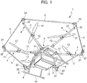
- FIG. 1 is a perspective view showing an exemplary configuration of flight equipment 1 according to an embodiment of the present invention.
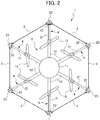
- FIG. 2 is a schematic planar view showing the flight equipment 1 of FIG. 1 . Note that FIG. 2 shows the flight equipment 1 schematically as compared with FIG. 1 , while omitting part of the configuration of the flight equipment 1.
- the flight equipment 1 includes: a drone (aerial vehicle) 2; protective members 3 stretched to surround an outside of the drone 2; and a plurality of supporters 4 mounted to the drone 2 and supporting the protective members 3.
- the drone 2 can fly independently with the protective members 3 and the supporters 4 detached therefrom, and it is conceivable to sell the drone 2 alone.
- the drone 2 includes: a body 11 housing an electronic device and the like that are necessary for processing for checking mounting suitability of the protective members 3 according to an embodiment of the present invention and for other control of the drone 2; a plurality of arms 12 that extend outward in a plane from the body 11; and a plurality of rotors 13 held by the body 11 via the arms 12.
- the drone 2 further includes, on the lower side of the body 11, legs 14 for contacting with the landing plane, a box 15 for accommodating a delivery target, and the like.
- the term “outside” means a side away from the body 11 in planar view when the center of gravity or center of the body 11 of the drone 2 is defined as the base point.
- the "outside” can also be expressed as radially outside while the base point is set to be the center of a sphere.
- the electronic device housed in the body 11 includes a computer device that performs processing according to an embodiment of the present invention to be described later, controls a motor for driving the rotors 13, transmits and receives signals to and from external devices such as a controller operated by an operator of the drone 2 (hereinafter the operator may be referred to also as the "user"), and performs processing based on information from various sensors such as a camera (not shown) provided on the body 11.
- a computer device that performs processing according to an embodiment of the present invention to be described later, controls a motor for driving the rotors 13, transmits and receives signals to and from external devices such as a controller operated by an operator of the drone 2 (hereinafter the operator may be referred to also as the "user"), and performs processing based on information from various sensors such as a camera (not shown) provided on the body 11.
- Each arm 12 is formed in a rod shape extending in a horizontal direction.
- One of the end portions of the arm 12 is connected to the body 11, and the other (hereinafter, referred to as the distal end portion) is provided with the rotor 13.
- the six arms 12 extend radially and symmetrically from the body 11 in planar view. The six arms 12 are equally spaced apart from each other in a circumferential direction.
- the rotors 13 are held by the body 11 via the arms 12. Specifically, each rotor 13 is rotatably provided on an upper surface of the distal end portion of an associated one of the arms 12. The rotors 13 are mounted to the arms 12 such that their planes of revolution coincide with a horizontal plane. In the present embodiment, each of the six arms 12 is provided with the rotor 13. The six rotors 13 in total of the drone 2 rotate to generate lift for the flight equipment 1 including the supporters 4 to fly.
- the protective members 3 are members that prevent the drone 2 from directly colliding with, for example, a building and a tree during flight of the flight equipment 1, and thereby protect the drone 2 from external impacts.
- each of the plurality of protective members 3 is held between distal end portions of adjacent ones of the supporters 4. Consequently, the plurality of protective members 3 together form a loop shape surrounding the drone 2 in planer view.
- stretching the protective members 3 to surround an outside of the rotors 13 as in the present embodiment makes it possible to prevent the rotors 13 from directly colliding with a building and the like during flight.
- Each protective member 3 may be constituted by a flexible material that cannot maintain its shape by itself, such as a rope, a wire, etc.
- the protective member 3 may be constituted by a stiff material that is substantially undeformable, such as a rod member.
- the protective members 3 are preferably constituted by a material which has stiffness allowing the protective members 3 to be stretched between the supporters 4, and which has flexibility and elasticity allowing the protective members 3 to deform to a certain extent that facilitates attachment and detachment of the protective members 3.
- CFRP carbon fiber reinforced plastics
- the protective member 3 be produced by molding a material with a certain elastic modulus into a band shape having a small thickness, and thereby configured as a member that has a flexibility allowing bending deformation in the thickness direction while having a sufficient stiffness in the width direction.
- band shape as used herein means a shape having an average width that is five times or more as large as an average thickness. Note that the average width and the average thickness shall be calculated without taking account of a structure for causing the supporters to hold end portions and a structure which may be provided between the supporters for a different purpose (not included in the present embodiment).
- the band-shaped protective member 3 is preferably supported such that the width direction thereof is substantially perpendicular to a rotation axis of the rotor 13.
- the protective member 3 can cushion the impact by contacting with the other object at a plane thereof, thereby making it possible to reduce damage to the other object.
- the protective member 3 which is arranged such that the thickness direction thereof is substantially perpendicular to the rotation axis of the rotor 13, resists flexure in a direction (vertical direction) parallel to the rotation axis of the rotor 13. That is, in the protective member 3, a flexural vibration (vertical shaking) in a direction parallel to the rotation axis of the rotor 13 is less likely to occur than a flexural vibration (horizontal shaking) in a direction (horizontal direction) perpendicular to the rotation axis of the rotor 13.
- the supporters 4 are instruments for supporting the protective members 3 stretched around the drone 2.
- the supporters 4 are attached to the distal end portions of the six arms 12 on a one-to-one basis.
- Each of the supporters 4 has: a fastenable part 21 that is mountable to the distal end portion of the arm 12 of the drone 2 and that extends substantially perpendicularly to the rotation axis of the rotor 13; an extension part 22 that is attached to a distal end portion of the fastenable part 21 and extends substantially parallel to the rotation axis of the rotor 13; and a holder part 23 that is attached to an upper end portion of the extension part 22 and holds end portions of the protective members 3.
- substantially perpendicular(ly) as used herein means that a relative angle is 85° or larger and 95° or smaller.
- substantially parallel means that a relative angle is 5° or smaller.
- the fastenable parts 21 extend horizontally outwardly from the arms 12 such that the protective members 3 are supported outside the rotors 13 in planar view.
- the fastenable part 21 can be configured as a rod-shaped member, but is preferably configured as a cylindrical member that can house control-related components to be described later.
- the extension parts 22 extend upward parallel to the rotation axes of the rotors 13, and accordingly, makes it possible to easily adjust a height of the holder parts 23, and thus, a height of the protective members 3 held by the holder parts 23. As a result, the protective members 3 can be supported at a height where the protective members 3 are prevented from contacting with the rotors 13.
- the extension part 22 can be constituted by a material that is relatively lightweight and sufficiently stiff. Examples of such a material include resin, aluminum alloy, fiber reinforced plastics.
- the extension part 22 is preferably formed into a band plate shape whose thickness direction is parallel to the direction in which the associated fastenable part 21 extends. In other words, it is preferable that the thickness direction of the extension part 22 be substantially perpendicular to the rotation axis of the rotor 13 and be toward the center of the body 11. Due to this configuration, a tension applied to the protective members 3 easily causes the extension parts 22 to elastically deform such that the distal end portions thereof move toward the body 11, thereby facilitating detection of the tension applied to the protective members 3.
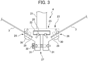
- each holder part 23 can be configured to have: a fastening structure 25 via which the holder part 23 is fastened to the extension part 22; a pair of holding structures 26 for holding end portions of the protective members 3; and a tension adjusting mechanism 27 that changes a tension applied to the protective members 3 by deforming the holder part 23 in planar view to change a distance between the pair of holding structures 26.
- the fastening structure 25 can be configured to have a fitting hole 28 into which the extension part 22 is fitted. To prevent the extension part 22 from coming off, the fastening structure 25 may have a separately-provided fastening screw. However, in the present embodiment, the fastening structure 25 is configured such that when the tension adjusting mechanism 27 increases the tension applied to the protective members 3, the fitting hole 28 decreases in size to tighten the extension part 22.
- Each holding structure 26 can be configured to have: a slit 29 into which the end portion of the protective member 3 is inserted; and a fastening screw 30 which is engageable with the protective member 3 inserted in the slit 29.
- the tension adjusting mechanism 27 can be configured to have: a pair of levers 31 that extend adjacent to each other from the fastening structures 25 toward the outside as viewed from the body 11; and an adjusting screw 32 for fixing a clearance between distal end potions of the pair of levers 31.
- the tension adjusting mechanism 27 can deform the entire holder part 23 such that each fastening structure 25 is pivoted around the extension part 22 toward the outside as viewed from the body 11. As a result, the holding structures 26 are pulled toward the tension adjusting mechanism 27, thereby increasing the tension applied to the protective members 3.
- the flight equipment 1 prevents the body 11 and the rotors 13 from directly colliding with buildings, trees, etc. when flying in the horizontal direction.
- the supporters 4 support the protective members 3 at the same height as the rotors 13 or at a position higher than the rotors 13.
- the legs 14 arranged below the body 11 and the rotors 13 can prevent damage to the body 11 and the rotors 13.
- the protective members 3, which are positioned at the same height as the rotors 13 or at a position higher than the rotors 13, can effectively prevent damage to the body 11 and the rotors 13.
- FIG. 4 is a block diagram showing a configuration for performing characteristic control in a flight system including the flight equipment 1 of FIG. 1 . Note that the entire flight system of FIG. 4 is per se a flight system according to an embodiment of the present invention.
- the flight system includes: the flight equipment 1; and an information processing apparatus 5 for remotely controlling the flight equipment 1.
- Each supporter 4 of the flight equipment 1 has a strain sensor 41 for detecting deformation of the extension part 22.
- the drone 2 includes: a plurality of detection circuits 42 for converting values detected by the strain sensors 41 into electrical signals; a mounting state determiner 43 for determining whether the supporters 4 support the protective members 3 in a suitable or unsuitable support state, based on the outputs of the plurality of detection circuits 42 (the values detected by the strain sensors 41); annunciators 44 for displaying information corresponding to a determination result of the mounting state determiner 43; a takeoff controller 45 for determining whether to permit takeoff of the flight equipment 1, based on the determination result of the mounting state determiner 43; and an aerial vehicle communication unit 46 for wireless communication with the information processing apparatus 5.
- a plurality of detection circuits 42 for converting values detected by the strain sensors 41 into electrical signals
- a mounting state determiner 43 for determining whether the supporters 4 support the protective members 3 in a suitable or unsuitable support state, based on the outputs of the plurality of detection circuits 42 (the values detected by the strain sensors 41)
- annunciators 44 for displaying information corresponding to a determination
- the strain sensors 41 of the supporters 4 and the detection circuits 42 of the drone 2 together form a support information detection unit for detecting support information (in the present embodiment, deformation of the extension parts 22) indicating the support state of the protective members 3 supported by the supporters 4.
- the information processing apparatus 5 includes: a remote communication unit 47 for wireless communication with the flight equipment 1; and a remote control unit 48 for performing processing necessary for remotely controlling the flight equipment 1.
- the strain sensor 41 can detect a degree of flexural deformation of the extension part 22 (a bend causing an upper end portion of the extension part 22 to move toward the body 11 side), which flexural deformation is caused by the tension applied to the protective members 3.
- the tension applied to the protective members 3 can be indirectly checked by way of the strain sensors 41.
- the strain sensor 41 it is preferable to affix the strain sensor 41 to the outer surface of the extension part 22 (the surface facing away from the body 11) as shown in FIG. 5 , or to the inner surface of the extension part 22 (the surface facing the body 11). Alternatively, it is preferable to affix the strain sensors 41 to both surfaces of the extension part 22. Since the band plate-shaped extension part 22 elastically deforms to a relatively large extent in accordance with the tension applied to the protective members 3, the tension applied to the protective members 3 can be relatively accurately determined by the strain sensor 41.
- any sensor detecting a strain caused by flexure of the extension part 22 can be used as the strain sensor 41.
- Examples of such a sensor for detecting a strain include a strain gauge whose electrical resistance is changed by a strain (by deformation of itself), a capacitance sensor whose capacitance is changed by a strain, etc.
- the detection circuit 42 is a circuit for outputting an electrical signal that varies in response to a change in electrical characteristics of the strain sensor 41.
- the detection circuit 42 may be constituted, for example, by a known Wheatstone bridge circuit. Specifically, in the case where the strain sensors 41 are affixed on both surfaces of the extension part 22, a Wheatstone bridge circuit according to the two gauge method is suitably used.
- the detection circuits 42 may be arranged in the arms 12 on a one-to-one basis, or may be arranged in the body 11. In the case of being arranged in the body 11, the plurality of detection circuits 42 may be formed on a single circuit board.
- a connector C may be provided between the strain sensor 41 and the detection circuit 42, the connector C enabling electrical connection between the strain sensor 41 and the detection circuit 42, while allowing the fastenable part 21 to be attached to and detached from the arm 12.
- the connector C may be configured to be pulled out from the arm 12 or the fastenable part 21 by way of a sufficiently long lead wire employed as the line L between the connector C and the strain sensor 41 or the detection circuit 42.
- the arm 12 and the fastenable part 21 may each have a connector C mechanically incorporated therein such that mechanical connection between the arm 12 and the fastenable part 21 results in electrical connection between the strain sensor 41 and the detection circuit 42.
- the mounting state determiner 43 determines whether the support state of the protective members 3 supported by the supporters 4 is suitable or unsuitable, based on the values detected by the strain sensors 41 (the outputs of the detection circuits 42) that constitute the support information. Specifically, the mounting state determiner 43 may be configured to determine that the supporters 4 unsuitably stretch the protective members 3 when the values (degrees of strain) detected by the strain sensors 41 corresponding to the tension applied to the protective members 3 are less than a preset lower limit value. Alternatively, the mounting state determiner 43 may be configured to determine that the support state of the protective members 3 is unsuitable when the values detected by the strain sensors 41 exceed a preset upper limit value. Furthermore, the mounting state determiner 43 may determine whether the support state of the protective members 3 is suitable or unsuitable while taking account of a relationship between the values detected by the plurality of strain sensors 41.
- the mounting state determiner 43 may be configured as an analog circuit including a comparator and the like, or may be configured to digitally convert the outputs of the detection circuits 42 and arithmetically process the outputs by a microprocessor.
- the mounting state determiner 43 may be formed on the same circuit board where part or all of the detection circuits 42 and the takeoff controller 45 are provided.
- the mounting state determiner 43 is preferably housed in the body 11. Further, the mounting state determiner 43 may be implemented as one function of a control device that also performs other control of the drone 2. In other words, the mounting state determiner 43 can be implemented by addition of a subroutine, a subprogram, or the like to the programs of the computer constituting the control device for the drone 2. Thus, the mounting state determiner 43 is to be functionally distinguishable, and does not need to be a physically independent component.
- FIG. 6 is a flowchart showing a control procedure performed by the takeoff controller 45 according to the present embodiment.
- Step S1 the takeoff controller 45 first acquires the outputs of the detection circuits 42 (the values detected by the strain sensors 41) as the support information.
- Step S2 the takeoff controller 45 checks whether all the detected values are equal to or greater than a preset first threshold. When it is confirmed that the values detected by the strain sensors 41 are all equal to or greater than the first threshold in Step S2, the procedure proceeds to Step S3, where it is checked whether a difference between a maximum and a minimum of the values detected by the strain sensors 41 is equal to or less than a preset second threshold.
- Step S4 When the difference between the maximum and the minimum of the values detected by the strain sensors 41 is determined to be equal to or less than the second threshold in Step S3, the procedure proceeds to Step S4, where a determination is made that all the supporters 4 support the protective members 3 in the suitable support state.
- Step S5 When the value detected by any of the strain sensors 41 is determined to be less than the first threshold in Step S2, and when the difference between the maximum and the minimum of the values detected by the strain sensors 41 is determined to exceed the threshold in step S3, the procedure proceeds to Step S5, where a determination is made that the support state of the protective members 3 supported by the supporters 4 is unsuitable.
- the annunciators 44 can have any configuration capable of conveying information to the user, such as an indicator lamp, a display panel, and a speaker.
- each annunciator 44 can be configured to have an LED that changes in lighting state in accordance with a determination result of the mounting state determiner 43.
- the LED of the annunciator 44 may be turned on only before takeoff, or before and after the takeoff.
- the change in the lighting state of the LED is not particularly limited as long as the change is recognizable for the user.
- Example of the change in the lighting state include a transition between the on and off states of the light, a change in an on period and an off period in blinking, a change in color of a LED of three-color emission type.
- the LEDs of the annunciators 44 may be used as indicator lamps for indicating the position and orientation of the drone 2 during flight.
- the annunciators 44 preferably announce the presence of the unsuitable support state such that it can be identified which of the supporters 4 supports the protective members 3 is in the unsuitable support state.
- the annunciators 44 may include a plurality of LEDs disposed at positions corresponding to the supporters (e.g., on the arms 12 or at positions on the body 11 adjacent to the arms 12), and may be configured to change the lighting state of the LED corresponding to the supporter 4 in the unsuitable support state.
- the annunciators 44 may include a display panel for displaying a letter or an image to allow identification of the supporter 4 in the unsuitable support state.
- the annunciators 44 may include a speaker, and may be configured to announce the supporter 4 in the unsuitable support state by a voice message or the like.
- the annunciators 44 may be configured to provide display corresponding to a determination result of the takeoff controller 45 to be described later: that is, the annunciators 44 may display whether takeoff is permitted.
- the takeoff controller 45 can be configured to permit takeoff of the flight equipment 1 only when all the mounting state determiners 43 determine that the support state of the protective members 3 supported by the respective supporters 4 is suitable. In other words, the takeoff controller 45 determines to permit the takeoff on the condition that all the supporters 4 support the protective members 3 in the suitable support state. In addition to this, a remaining battery level and a GPS signal reception status are also set as the condition for permitting takeoff.
- the takeoff controller 45 can be provided in the body 11.
- the takeoff controller 45 may be implemented as one function of the control device that also performs other control of the drone 2.
- the takeoff controller 45 can be implemented by addition of a subroutine, a subprogram, or the like to the programs of the computer constituting control device of the drone 2. Therefore, the takeoff controller 45 is to be functionally distinguishable, and does not need to be a physically independent component.
- the aerial vehicle communication unit 46 and the remote communication unit 47 are each a transmitting-receiving device intended for wireless communication.
- a frequency and an output of a radio wave (including light) transmitted and received by the aerial vehicle communication unit 46 and the remote communication unit 47, and a communication method of the aerial vehicle communication unit 46 and the remote communication unit 47 can be appropriately selected in accordance with the purpose of use of the flight equipment 1, for example.
- the remote control unit 48 is a device for providing the flight equipment 1 with instructions on a flight path, a flight speed, and operations such as shooting by a camera.
- the remote control unit may be constituted by a programmable computer.
- the remote control unit 48 may be configured to cause the flight equipment 1 to make emergency landing upon receiving a determination result of the mounting state determiner 43 that the support state of the protective members 3 supported by the supporters 4 is unsuitable, during flight of the flight equipment 1.
- the information processing apparatus 5 including the remote communication unit 47 and the remote control unit 48 may be constituted by a commercially available computer device (e.g., a smartphone, a tablet, a personal computer, etc.) having communication facility and including a dedicated program loaded therein.
- a commercially available computer device e.g., a smartphone, a tablet, a personal computer, etc.
- the information processing apparatus 5 may be configured to display a determination result of the mounting state determiner 43 and a determination result of the takeoff controller 45.
- the determination result of the mounting state determiner 43 is preferably displayed to allow identification of a supporter 4 that has been determined to support the protective members 3 in the unsuitable support state. Therefore, it is preferable that the drone 2 transmit at least one of the determination result of the mounting state determiner 43 or the determination result of the takeoff controller 45 to the information processing apparatus 5, using the aerial vehicle communication unit 46 and the remote communication unit 47.
- the information processing apparatus 5 allows the user to check whether the support state of the protective members 3 is suitable or unsuitable.
- the mounting state determiner 43 is capable of checking whether the protective members 3 are suitably supported by the supporters 4 by way of the values detected by the strain sensors 41 (support information). Consequently, in the flight equipment 1, the protective members 3 can be reliably mounted to the drone 2 when the flight equipment 1 is used.
- the configuration in which the strain sensors 41 detect the strain caused by the tension applied to the protective members 3 ensures that the protective members 3 are under a suitable tension, whereby the protective members 3 can sufficiently exhibit impact absorbing performance. Further, in the flight equipment 1, since each supporter 4 has the strain sensor 41, it can be ensured that all of the plurality of protective members 3 suitably support the protective members 3.
- the flight equipment 1 which includes the annunciators 44, allows the user to easily check whether the support state of the protective members 3 is suitable or unsuitable. Further, even when the user neglects to check the suitability of the support state of the protective members 3, the takeoff controller 45 included in the flight equipment 1 can prevent flight of the flight equipment 1 when the protective members 3 are in the unsuitable support state.
- the flight system of the present embodiment includes: flight equipment 1a; and an information processing apparatus 5a.
- the mechanical configuration of the flight equipment 1a of the present embodiment is the same or similar to that of the flight equipment 1 shown in FIG. 1 , whereas a control-related configuration of the flight equipment 1a solely constitutes a difference from the flight equipment 1. Therefore, in the following description, components that are the same as those described earlier are denoted by the same reference characters, and detailed description thereof will be omitted.
- FIG. 7 is a block diagram showing a configuration for performing characteristic control in the flight system of the present embodiment.
- the flight equipment 1a includes supporters 4 each of which has: a strain sensor 41a for detecting deformation of a holder part 23 as support information; a detection circuit 42a for converting a value detected by the strain sensor 41a into an electrical signal; a mounting state determiner 43a for determining whether a support state of protective members 3 supported by the supporters 4 is suitable or unsuitable, based on an output of the detection circuit 42a (the value detected by the strain sensor 41a); and an annunciator 44a for displaying information corresponding to a determination result of the mounting state determiner 43a.
- the detection circuit 42a and the mounting state determiner 43a are preferably arranged inside a fastenable part 21 of the supporter 4.
- a drone 2 has an aerial vehicle communication unit 46 configured to transmit determination results of the mounting state determiners 43a of the supporters 4 via wireless communication with the information processing apparatus 5a.
- the information processing apparatus 5a includes: a remote communication unit 47 for wireless communication with the flight equipment 1a; a takeoff controller 45a for determining whether to permit takeoff of the flight equipment 1a, based on determination results of the mounting state determiners 43a; and a remote control unit 48 for performing other processing necessary for remotely controlling the flight equipment 1a.
- the strain sensor 41a is affixed to a surface of a holder part 23, the surface facing a body 11.
- the strain sensor 41a has a pair of terminals 49 arranged on an inner surface of a fitting hole 28.
- two wires 50 are arranged so as to be in electric contact with the terminals 49 in a state where the holder part 23 have been attached to the extension part 22.
- planar conductors be exposed in a contact portion between the terminals 49 and the wires 50.
- the surface of the holder part 23 to which the strain sensor 41a is affixed deforms to become convex toward the body 11.
- the strain sensor 41a detects this deformation of the holder part 23.
- the detection circuit 42a is designed to be arrangeable in the supporter 4, but in electrical terms, can have the same circuit configuration as of the detection circuit 42 shown in FIG. 4 .
- the mounting state determiner 43a determines that the associated supporter 4 supports the protective members 3 in the unsuitable support state when a value detected by the associated strain sensor 41a is less than a preset lower limit value or greater than a preset upper limit value.
- the mounting state determiner 43a can be constituted by an analogue circuit or a circuit having a microprocessor, and may be formed on the same circuit board where the detection circuit 42a is formed.
- the annunciator 44a has the same function as of the annunciator 44 shown in FIG. 4 .
- This configuration simplifies the wiring from the mounting state determiner 43a arranged in the supporter 4.
- the annunciators 44a arranged on the supporters 4 allow the user to further easily identify which of the supporters 4 supports the protective members 3 in an unsuitable state.
- a takeoff controller 45a is implemented by a program of a computer device constituting the information processing apparatus, and is integral with the remote control unit 48.
- the wiring between the mounting state determiner 43 and the aerial vehicle communication unit 46 preferably includes, in addition to a signal line Ls through which a signal is transmitted and received between the aerial vehicle communication unit 46 and the mounting state determiner 43, a power line Lp through which power is supplied from the aerial vehicle communication unit 46 to the mounting state determiner 43.
- the information processing apparatus 5a has the takeoff controller 45a. Therefore, the drone 2 wirelessly transmits determination results of the mounting state determiners 43a to the information processing apparatus 5a. This configuration allows the information processing apparatus 5a to prohibit flight of the flight equipment 1a when the support state of the protective members 3 is unsuitable.
- the flight system shown in FIG. 9 includes: flight equipment 1b; and an information processing apparatus 5b according to an embodiment of the present invention.
- the mechanical configuration of the flight equipment 1b of the present embodiment is the same or similar to the mechanical configuration of the flight equipment 1 shown in FIG. 1 , whereas a control-related configuration of the flight equipment 1b solely constitutes a difference from the flight equipment 1.
- FIG. 9 is a block diagram showing a configuration for performing characteristic control in the flight system of the present embodiment.
- the flight equipment 1b includes supporters 4, each of which has a strain sensor 41 for detecting deformation of a holder part 23 as support information.
- a drone 2 has: a plurality of detection circuits 42a for converting values detected by the strain sensors 41 (the support information) into respective electrical signals; and an aerial vehicle communication unit 46 for wireless communication with the information processing apparatus 5b.
- the information processing apparatus 5b includes: a remote communication unit 47 for wireless communication with the flight equipment 1b; a mounting state determiner 43b for comprehensively determining whether a support state of protective members 3 supported by the supporters 4 is suitable or unsuitable, based on outputs of the plurality of detection circuits 42 (the values detected by the strain sensors 41); an annunciator 44b for displaying information corresponding to a determination result of the mounting state determiner 43b; a takeoff controller 45b for determining whether to permit takeoff of the flight equipment 1b, based on the determination result of the mounting state determiner 43b; and a remote control unit 48 for performing other processing necessary for remotely controlling the flight equipment 1b.
- each strain sensor 41 of the present embodiment detects flexural deformation of an extension part 22 of the associated supporter 4, which flexural deformation is caused by a tension applied to the protective members 3.
- Each detection circuit 42 of the present embodiment can have the same or similar configuration to that of the detection circuit 42 shown in FIG. 4 .
- the information processing apparatus 5b of the flight system shown in FIG. 9 is per se an information processing apparatus according to an embodiment of the present invention.
- the remote communication unit 47 functions as a support information acquisition unit for acquiring support information (the values detected by the strain sensors 41) indicating a support state of the protective members 3 supported by the supporters 4.
- the mounting state determiner 43b and the takeoff controller 45b are provided in the information processing apparatus 5b.
- Each of the mounting state determiner 43b and the takeoff controller 45b can be implemented as part of a program of a computer device constituting the information processing apparatus 5b.
- the mounting state determiner 43b determines whether the support state of the protective members 3 supported by the supporters 4 is suitable or unsuitable, based on outputs of the detection circuits 42 (values detected by the strain sensors 41) that are input to the mounting state determiner 43b via the aerial vehicle communication unit 46 and the remote communication unit 47.
- the processing carried out by the mounting state determiner 43b and the takeoff controller 45b of the information processing apparatus 5b shown in FIG. 9 may be the same or similar to the processing carried out by the mounting state determiner 43 and the takeoff controller 45 of the flight equipment 1 shown in FIG. 4 .
- the annunciator 44b can be constituted by a display panel, a speaker, etc. of the computer device constituting the information processing apparatus 5b, for example.
- the annunciator 44b preferably displays the presence of the unsuitable support state such that it can be identified which of the supporters 4 supports the protective members in the unsuitable support state, and displays a determination result of the takeoff controller 45b.
- the information processing apparatus 5b of the present embodiment can prohibit flight of the flight equipment 1b, and can ensure that the protective members 3 are reliably mounted to the flight equipment 1b via the supporters 4.
- the flight equipment according to each embodiment of the present invention does not have to include the dedicated protective member, and a protective member provided separately by the user may be used in the flight equipment.
- a protective member provided separately by the user may be used in the flight equipment.
- Examples of general-purpose articles usable as the protective member include various ropes and wires, resin bands and metal bands for packaging or binding, etc.
- the strain sensor may be arranged to detect deformation of a different portion of the supporter.
- the strain sensor does not need to be provided to every supporter.
- arranging at least one strain sensor so as to detect deformation of any one of the supporters makes it possible to presume support states of all the protective members that are connected to one another in a loop shape.
- the strain sensor shown in FIG. 8 may be employed as the strain sensor of the embodiments shown in FIGS. 4 and 9 .
- the strain sensor shown in FIG. 5 may be employed as the strain sensor of the embodiment shown in FIG. 7 .
- a support information detection unit may be configured to acquire the support information by way of a sensor other than the strain sensor, such as a distance sensor for measuring, for example, a distance between the body and a distal end portion of the supporter.
- the support information detection unit may detect, as the support information, a change in a state of a sensor provided to the protective member.
- the support information detection unit may detect the support information in binary.
- the flight equipment according to each embodiment of the present invention may be configured to wirelessly transmit a signal between the aerial vehicle and the supporters.
- the flight equipment of one or more embodiments of the present invention may include a battery in the supporter, and a wireless transmitter in place of the connector of the embodiment described above.
- the flight equipment of one or more embodiments of the present invention may be configured to supply power from the aerial vehicle to the supporters wirelessly.
- the supporter may be configured to apply a tension to the protective members by changing a distance from the body to the distal end portion of the supporter.
- the number of the supporters is not limited to six, but can be any number equal to or greater than three.
- the protective member may be embodied as a single loop-shaped member supported by the plurality of supporters.
- the plurality of supporters can support the protective member such that the protective member is movable in the length direction thereof, and at least one of the supporters can have a mechanism for applying a tension to the protective member.
- the holder part to which the protective member is not fastened may have a ring, a guide groove, a pulley, etc., for guiding the protective member.
- the flight equipment according to each embodiment of the present invention may further include a mechanism that adjusts a tension applied to the protective member without moving the distal end portion of the supporter, such as a mechanism that applies the tension by moving an end of the protective member in a stretching direction.
- the flight equipment according to each embodiment of the present invention may be configured such that a plurality of supporters three-dimensionally hold the protective members.
- a plurality of supporters three-dimensionally hold the protective members.
- vertically-extending supporters can be provided.
- These supports can have the protective members stretched between distal end portions thereof so as to surround at least the body of the aerial vehicle also in side view.
- the drone is exemplified as the aerial vehicle.
- the aerial vehicle is not particularly limited to the drone, and any aerial vehicle including a manned aerial vehicle may be employed suitably.
- the embodiments of the present invention achieve advantageous effects due to the following configurations.
- Flight equipment e.g., flight equipment 1, 1a
- Flight equipment includes: an aerial vehicle (e.g., a drone 2) having a body (e.g., a body 11) and at least one rotor (e.g., a rotor 13) held on the body; a plurality of supporters (e.g., supporters 4) mounted to the aerial vehicle and supporting a protective member (e.g., a protective member 3) stretched therebetween so as to surround an outside of the body; a support information detection unit (e.g., strain sensors 41, 41a and a detection circuits 42, 42a) configured to detect support information indicating a support state of the protective member; and a mounting state determiner (e.g., a mounting state determiner 43, 43a) configured to determine whether the support state of the protective member is suitable or unsuitable, based on a value detected by the support information detection unit.
- the support information detection unit allows checking the support state of the supporters.
- the mounting state of the supporters e.g.,
- the support information detection unit may have a strain sensor (e.g., a strain sensor 41, 41a) configured to detect deformation of the supporter, the deformation being caused by a tension applied to the protective member.
- a strain sensor e.g., a strain sensor 41, 41a
- This feature in which the strain sensor detects a strain caused by a tension applied to the protective member ensures that the protective member is under a suitable tension, thereby enabling the protective member to sufficiently exhibit impact absorbing performance.
- the supporter may have: a fastenable part (e.g., a fastenable part 21) mounted to the aerial vehicle and extending substantially perpendicularly to a rotation axis of the rotor; and an extension part (e.g., an extension part 22) attached to a distal end portion of the fastenable part and extending substantially parallel to the rotation axis of the rotor, and the strain sensor may be arranged on the extension part.
- a fastenable part e.g., a fastenable part 21
- an extension part e.g., an extension part 22
- the strain sensor may be arranged on the extension part.
- the strain sensor may include a plurality of strain sensors that are arranged on the plurality of supporters on a one-to-one basis. This feature can ensure that all the supporters support the protective members while applying a suitable tension to the protective members.
- the mounting state determiner may determine that the support state of the protective member is unsuitable when a difference between a maximum and a minimum of values detected by the support information detection unit exceeds a preset threshold. This feature can prevent stress concentration and abnormal vibration which can be caused by a situation where the plurality of supporters ununiformly support the protective member, whereby the protective member can be prevented from providing insufficient protection.
- the mounting state determiner may be arranged on the supporter. This feature ensures that the plurality of protective members are all suitably mounted.
- the aerial vehicle or the supporters may further include an annunciator (e.g., annunciator 44, 44a) configured to announce information corresponding to a determination result of the mounting state determiner. This feature allows the user to easily appreciate the support state of the protective member.
- an annunciator e.g., annunciator 44, 44a
- the annunciator may be configured to announce the information such that it can be identified which of the plurality of supporters supports the protective member in the unsuitable support state. This feature allows the user to easily identify the supporter supporting the protective members in the unsuitable support state and to adjust and bring the identified supporter into a suitable support state.
- Flight equipment may further include a takeoff controller (e.g., a takeoff controller 45, 45a) configured to determine whether to permit takeoff of the flight equipment, based on a determination result of the mounting state determiner. Even when the user neglects to check the suitability of the support state of the protective members, this feature can prevent flight of the flight equipment having the protective members being in the unsuitable support state.
- a takeoff controller e.g., a takeoff controller 45, 45a
- this feature can prevent flight of the flight equipment having the protective members being in the unsuitable support state.
- a flight system includes: the above-described flight equipment (e.g., the flight equipment 1); and an information processing apparatus (e.g., an information processing apparatus 5) configured to wirelessly communicate with the flight equipment and to control flight of the flight equipment, wherein the aerial vehicle transmits a determination result of the takeoff controller (e.g., a takeoff controller 45) to the information processing apparatus.
- the takeoff controller prohibits flight of the flight equipment, this feature makes it possible for the information processing apparatus to confirm the prohibition.
- a flight system includes: the above-described flight equipment (e.g., the flight equipment 1); and an information processing apparatus (e.g., an information processing apparatus 5) configured to wirelessly communicate with the flight equipment and to control flight of the flight equipment, wherein the aerial vehicle transmits a determination result of the mounting state determiner to the information processing apparatus.
- the information processing apparatus can prohibit flight of the flight equipment when the protective member of the flight equipment is in the unsuitable support state. Thus, protection of the aerial vehicle can be ensured.
- a flight system includes: the above-described flight equipment (e.g., the flight equipment 1a); and an information processing apparatus (e.g., an information processing apparatus 5a) configured to wirelessly communicate with the flight equipment and to control flight of the flight equipment, wherein the aerial vehicle transmits a determination result of the mounting state determiner to the information processing apparatus, and the information processing apparatus has a takeoff controller (e.g., a takeoff controller 45a) configured to determine whether to permit takeoff of the flight equipment, based on the determination result of the mounting state determiner.
- a takeoff controller e.g., a takeoff controller 45a
- This feature also allows the information processing apparatus to prohibit flight of the flight equipment having the protective member supported in the unsuitable support state. Thus, protection of the aerial vehicle can be ensured.
- a flight system includes: flight equipment (e.g., flight equipment 1b); and an information processing apparatus (e.g., an information processing apparatus 5b) configured to wirelessly communicate with the fight equipment and to control flight of the flight equipment, wherein the flight equipment has: an aerial vehicle (e.g., a drone 2) having a body and at least one rotor held on the body; a plurality of supporters (e.g., supporters 4) mounted to the aerial vehicle and supporting a protective member stretched therebetween so as to surround an outside of the body; and a support information detection unit (e.g., strain sensors 41 and detection circuits 42) configured to detect support information indicating a support state of the protective member, and the information processing apparatus has a mounting state determiner (e.g., a mounting state determiner 43b) configured to determine whether the support state of the protective member is suitable or unsuitable, based on the support information.
- the information processing apparatus can determine whether the protective member is supported in the suitable or unsuitable support state.
- An information processing apparatus (e.g., an information processing apparatus 5b) according to an embodiment of the present invention is intended for controlling flight equipment (e.g., flight equipment 1b) including an aerial vehicle having a body and at least one rotor held on the body, and including a plurality of supporters mounted to the aerial vehicle and supporting a protective member stretched therebetween so as to surround an outside of the body.
- the information processing apparatus comprising: a support information acquisition unit (e.g., remote communication unit 47) configured to acquire support information indicating a support state of the protective member; and a mounting state determiner (e.g., a mounting state determiner 43b) configured to determine whether the support state of the protective member is suitable or unsuitable, based on the support information acquired by the support information acquisition unit. This feature makes it possible to check the support state of the protective member and to ensure the protective member is suitably mounted to the aerial vehicle when the flight vehicle flies.
- a support information acquisition unit e.g., remote communication unit 47
- a mounting state determiner e
Landscapes
- Engineering & Computer Science (AREA)
- Aviation & Aerospace Engineering (AREA)
- Remote Sensing (AREA)
- Mechanical Engineering (AREA)
- Radar, Positioning & Navigation (AREA)
- Physics & Mathematics (AREA)
- General Physics & Mathematics (AREA)
- Automation & Control Theory (AREA)
- Toys (AREA)
Abstract
Description
- The present invention relates to flight equipment, a flight system and an information processing apparatus.
- Aerial vehicles such as drones have been conventionally known which freely move in midair with the help of lift generated by rotation of rotors thereof. The rotors and other components of an aerial vehicle of this type can be damaged by contact that may be caused when the aerial vehicle collides with a tree or a building due to maneuvering by the user or influence of wind, or when the aerial vehicle makes an emergency landing on the ground. Since such damage to the rotors may hinder flight, a technique to mount a protective member (safety frame) to an aerial vehicle (drone) for preventing the rotors and other components from being damaged or distorted by an external impact has been proposed (see, for example, Patent Document 1).
- Patent Document 1: Japanese Patent No.
6376672 - However, known techniques including the technique disclosed in
Patent Document 1 assign importance to only the protection of the rotors and other components, and have room for improvement from the viewpoints of mountability of the protective member to an aerial vehicle and portability of flight equipment including the protective member. Specifically, the protective member ofPatent Document 1 is composed of a large number of plastic pipes and a plurality of joints. The plastic pipes are fitted into, and connected to, the joints, whereby the plastic pipes and the joints are assembled into a shape covering an aerial vehicle. The protective member ofPatent Document 1 is assembled in a very complicated manner, and is designed without taking account of a possibility of detaching the protective member after use. If the protective member ofPatent Document 1 was attached and detached before and after every use, it would be impossible to ensure the proper connection of the plastic pipes, and a part of the protective member may fall. - One or more embodiments of the present invention has been attained in view of the foregoing background, and is intend to achieve an object of providing flight equipment including an aerial vehicle and a protective member reliably mounted to the aerial vehicle, and providing a flight system and an information processing apparatus.
- To achieve the above object, flight equipment according to an embodiment of the present invention includes: an aerial vehicle having a body and at least one rotor held on the body; a plurality of supporters mounted to the aerial vehicle and supporting a protective member stretched therebetween so as to surround an outside of the body; a support information detection unit configured to detect support information indicating a support state of the protective member; and a mounting state determiner configured to determine whether the support state of the protective member is suitable or unsuitable, based on the support information.
- One or more embodiments of the present invention provides flight equipment including an aerial vehicle and a protective member reliably mounted to the aerial vehicle, a flight system and an information processing apparatus.
-
-
FIG. 1 is a perspective view showing an exemplary configuration of flight equipment according to an embodiment of the present invention; -
FIG. 2 is a schematic planar view showing the flight equipment ofFIG. 1 ; -
FIG. 3 is a planar view showing a supporter of the flight equipment ofFIG. 1 ; -
FIG. 4 is a block diagram showing an exemplary configuration of a flight system according to an embodiment of the present invention, the flight system including the flight equipment ofFIG. 1 ; -
FIG. 5 is a perspective view of a supporter having a strain sensor of the flight system ofFIG. 5 attached thereto; -
FIG. 6 is a flowchart showing a control procedure performed by a takeoff controller of the flight system ofFIG. 4 ; -
FIG. 7 is a block diagram showing a flight system according to an embodiment different from that shown inFIG. 4 ; -
FIG. 8 is a partially exploded perspective view of a supporter, and shows a structure for attaching a strain sensor of the flight system ofFIG. 7 ; and -
FIG. 9 is a block diagram of a flight system according to an embodiment different from those shown inFIGS. 4 and7 . - Embodiments of the present invention will be described below with reference to the drawings. In the following description, unless otherwise noted, the plane on which a drone as an aerial vehicle lands is referred to as the "landing plane", and in particular, a direction in which the drone takes off as viewed from the landing plane is referred to as the "upward direction", while the direction opposite to the "upward direction" is referred to as the "downward direction". In addition, a distance from the landing plane in the upper direction is referred to as "height", and the "vertical direction" is defined to coincide with the upward/downward direction.
-
FIG. 1 is a perspective view showing an exemplary configuration offlight equipment 1 according to an embodiment of the present invention.FIG. 2 is a schematic planar view showing theflight equipment 1 ofFIG. 1 . Note thatFIG. 2 shows theflight equipment 1 schematically as compared withFIG. 1 , while omitting part of the configuration of theflight equipment 1. - First, the mechanical configuration of the
flight equipment 1 will be described. - As shown in
FIGS. 1 and2 , theflight equipment 1 includes: a drone (aerial vehicle) 2;protective members 3 stretched to surround an outside of thedrone 2; and a plurality ofsupporters 4 mounted to thedrone 2 and supporting theprotective members 3. - The
drone 2 can fly independently with theprotective members 3 and thesupporters 4 detached therefrom, and it is conceivable to sell thedrone 2 alone. - The
drone 2 includes: abody 11 housing an electronic device and the like that are necessary for processing for checking mounting suitability of theprotective members 3 according to an embodiment of the present invention and for other control of thedrone 2; a plurality ofarms 12 that extend outward in a plane from thebody 11; and a plurality ofrotors 13 held by thebody 11 via thearms 12. Thedrone 2 further includes, on the lower side of thebody 11,legs 14 for contacting with the landing plane, abox 15 for accommodating a delivery target, and the like. Here, the term "outside" means a side away from thebody 11 in planar view when the center of gravity or center of thebody 11 of thedrone 2 is defined as the base point. The "outside" can also be expressed as radially outside while the base point is set to be the center of a sphere. - The electronic device housed in the
body 11 includes a computer device that performs processing according to an embodiment of the present invention to be described later, controls a motor for driving therotors 13, transmits and receives signals to and from external devices such as a controller operated by an operator of the drone 2 (hereinafter the operator may be referred to also as the "user"), and performs processing based on information from various sensors such as a camera (not shown) provided on thebody 11. - Each
arm 12 is formed in a rod shape extending in a horizontal direction. One of the end portions of thearm 12 is connected to thebody 11, and the other (hereinafter, referred to as the distal end portion) is provided with therotor 13. In the present embodiment, the sixarms 12 extend radially and symmetrically from thebody 11 in planar view. The sixarms 12 are equally spaced apart from each other in a circumferential direction. - The
rotors 13 are held by thebody 11 via thearms 12. Specifically, eachrotor 13 is rotatably provided on an upper surface of the distal end portion of an associated one of thearms 12. Therotors 13 are mounted to thearms 12 such that their planes of revolution coincide with a horizontal plane. In the present embodiment, each of the sixarms 12 is provided with therotor 13. The sixrotors 13 in total of thedrone 2 rotate to generate lift for theflight equipment 1 including thesupporters 4 to fly. - The
protective members 3 are members that prevent thedrone 2 from directly colliding with, for example, a building and a tree during flight of theflight equipment 1, and thereby protect thedrone 2 from external impacts. - In the present embodiment, each of the plurality of
protective members 3 is held between distal end portions of adjacent ones of thesupporters 4. Consequently, the plurality ofprotective members 3 together form a loop shape surrounding thedrone 2 in planer view. - Although it is suitable to stretch the
protective members 3 so as to surround at least thebody 11, stretching theprotective members 3 to surround an outside of therotors 13 as in the present embodiment makes it possible to prevent therotors 13 from directly colliding with a building and the like during flight. - Each
protective member 3 may be constituted by a flexible material that cannot maintain its shape by itself, such as a rope, a wire, etc. Alternatively, theprotective member 3 may be constituted by a stiff material that is substantially undeformable, such as a rod member. However, theprotective members 3 are preferably constituted by a material which has stiffness allowing theprotective members 3 to be stretched between thesupporters 4, and which has flexibility and elasticity allowing theprotective members 3 to deform to a certain extent that facilitates attachment and detachment of theprotective members 3. As such a material having stiffness, flexibility and elasticity, an elongated band-shaped member made of a composite material such as carbon fiber reinforced plastics (CFRP) can be sufficiently employed. In other words, it is desirable that theprotective member 3 be produced by molding a material with a certain elastic modulus into a band shape having a small thickness, and thereby configured as a member that has a flexibility allowing bending deformation in the thickness direction while having a sufficient stiffness in the width direction. The term "band shape" as used herein means a shape having an average width that is five times or more as large as an average thickness. Note that the average width and the average thickness shall be calculated without taking account of a structure for causing the supporters to hold end portions and a structure which may be provided between the supporters for a different purpose (not included in the present embodiment). - The band-shaped
protective member 3 is preferably supported such that the width direction thereof is substantially perpendicular to a rotation axis of therotor 13. Thus, when theflight equipment 1 collides with another object (including a person, an animal, etc.) in the radial direction of therotor 13, theprotective member 3 can cushion the impact by contacting with the other object at a plane thereof, thereby making it possible to reduce damage to the other object. - Further, the
protective member 3, which is arranged such that the thickness direction thereof is substantially perpendicular to the rotation axis of therotor 13, resists flexure in a direction (vertical direction) parallel to the rotation axis of therotor 13. That is, in theprotective member 3, a flexural vibration (vertical shaking) in a direction parallel to the rotation axis of therotor 13 is less likely to occur than a flexural vibration (horizontal shaking) in a direction (horizontal direction) perpendicular to the rotation axis of therotor 13. As a result, even if a flexural vibration occurs in theprotective member 3 that is held so as not to overlap with therotor 13 as viewed in the radial direction, since a component in the direction of the rotation axis of therotor 13 is small, theprotective member 3 is less likely to contact with therotor 13. - The
supporters 4 are instruments for supporting theprotective members 3 stretched around thedrone 2. In the present embodiment, thesupporters 4 are attached to the distal end portions of the sixarms 12 on a one-to-one basis. - Each of the
supporters 4 has: afastenable part 21 that is mountable to the distal end portion of thearm 12 of thedrone 2 and that extends substantially perpendicularly to the rotation axis of therotor 13; anextension part 22 that is attached to a distal end portion of thefastenable part 21 and extends substantially parallel to the rotation axis of therotor 13; and aholder part 23 that is attached to an upper end portion of theextension part 22 and holds end portions of theprotective members 3. Note that "substantially perpendicular(ly)" as used herein means that a relative angle is 85° or larger and 95° or smaller. Further, "substantially parallel" means that a relative angle is 5° or smaller. - The
fastenable parts 21 extend horizontally outwardly from thearms 12 such that theprotective members 3 are supported outside therotors 13 in planar view. Thefastenable part 21 can be configured as a rod-shaped member, but is preferably configured as a cylindrical member that can house control-related components to be described later. - The
extension parts 22 extend upward parallel to the rotation axes of therotors 13, and accordingly, makes it possible to easily adjust a height of theholder parts 23, and thus, a height of theprotective members 3 held by theholder parts 23. As a result, theprotective members 3 can be supported at a height where theprotective members 3 are prevented from contacting with therotors 13. - The
extension part 22 can be constituted by a material that is relatively lightweight and sufficiently stiff. Examples of such a material include resin, aluminum alloy, fiber reinforced plastics. - The
extension part 22 is preferably formed into a band plate shape whose thickness direction is parallel to the direction in which the associatedfastenable part 21 extends. In other words, it is preferable that the thickness direction of theextension part 22 be substantially perpendicular to the rotation axis of therotor 13 and be toward the center of thebody 11. Due to this configuration, a tension applied to theprotective members 3 easily causes theextension parts 22 to elastically deform such that the distal end portions thereof move toward thebody 11, thereby facilitating detection of the tension applied to theprotective members 3. - As shown in
FIG. 3 , eachholder part 23 can be configured to have: afastening structure 25 via which theholder part 23 is fastened to theextension part 22; a pair of holdingstructures 26 for holding end portions of theprotective members 3; and atension adjusting mechanism 27 that changes a tension applied to theprotective members 3 by deforming theholder part 23 in planar view to change a distance between the pair of holdingstructures 26. - The
fastening structure 25 can be configured to have afitting hole 28 into which theextension part 22 is fitted. To prevent theextension part 22 from coming off, thefastening structure 25 may have a separately-provided fastening screw. However, in the present embodiment, thefastening structure 25 is configured such that when thetension adjusting mechanism 27 increases the tension applied to theprotective members 3, thefitting hole 28 decreases in size to tighten theextension part 22. - Each holding
structure 26 can be configured to have: aslit 29 into which the end portion of theprotective member 3 is inserted; and afastening screw 30 which is engageable with theprotective member 3 inserted in theslit 29. - The
tension adjusting mechanism 27 can be configured to have: a pair oflevers 31 that extend adjacent to each other from thefastening structures 25 toward the outside as viewed from thebody 11; and an adjustingscrew 32 for fixing a clearance between distal end potions of the pair oflevers 31. When the adjustingscrew 32 is tightened to narrow the clearance between the distal end potions of the pair oflevers 31, thetension adjusting mechanism 27 can deform theentire holder part 23 such that eachfastening structure 25 is pivoted around theextension part 22 toward the outside as viewed from thebody 11. As a result, the holdingstructures 26 are pulled toward thetension adjusting mechanism 27, thereby increasing the tension applied to theprotective members 3. - Thanks to the configuration in which the
supporters 4 support theprotective members 3 so as to surround thebody 11 and therotors 13, theflight equipment 1 prevents thebody 11 and therotors 13 from directly colliding with buildings, trees, etc. when flying in the horizontal direction. Thesupporters 4 support theprotective members 3 at the same height as therotors 13 or at a position higher than therotors 13. Thus, at the time of descending, thelegs 14 arranged below thebody 11 and therotors 13 can prevent damage to thebody 11 and therotors 13. At the time of ascending, theprotective members 3, which are positioned at the same height as therotors 13 or at a position higher than therotors 13, can effectively prevent damage to thebody 11 and therotors 13. - Next, a control configuration peculiar to the
flight equipment 1 of the present embodiment will be described. -
FIG. 4 is a block diagram showing a configuration for performing characteristic control in a flight system including theflight equipment 1 ofFIG. 1 . Note that the entire flight system ofFIG. 4 is per se a flight system according to an embodiment of the present invention. - The flight system includes: the
flight equipment 1; and aninformation processing apparatus 5 for remotely controlling theflight equipment 1. - Each
supporter 4 of theflight equipment 1 has astrain sensor 41 for detecting deformation of theextension part 22. - On the other hand, the
drone 2 includes: a plurality ofdetection circuits 42 for converting values detected by thestrain sensors 41 into electrical signals; a mountingstate determiner 43 for determining whether thesupporters 4 support theprotective members 3 in a suitable or unsuitable support state, based on the outputs of the plurality of detection circuits 42 (the values detected by the strain sensors 41);annunciators 44 for displaying information corresponding to a determination result of the mountingstate determiner 43; atakeoff controller 45 for determining whether to permit takeoff of theflight equipment 1, based on the determination result of the mountingstate determiner 43; and an aerialvehicle communication unit 46 for wireless communication with theinformation processing apparatus 5. - The
strain sensors 41 of thesupporters 4 and thedetection circuits 42 of thedrone 2 together form a support information detection unit for detecting support information (in the present embodiment, deformation of the extension parts 22) indicating the support state of theprotective members 3 supported by thesupporters 4. - The
information processing apparatus 5 includes: aremote communication unit 47 for wireless communication with theflight equipment 1; and aremote control unit 48 for performing processing necessary for remotely controlling theflight equipment 1. - Being affixed to the
extension part 22, thestrain sensor 41 can detect a degree of flexural deformation of the extension part 22 (a bend causing an upper end portion of theextension part 22 to move toward thebody 11 side), which flexural deformation is caused by the tension applied to theprotective members 3. In other words, the stronger the tension applied to theprotective members 3 is, the greater the value detected by thestrain sensor 41 is. Thus, the tension applied to theprotective members 3 can be indirectly checked by way of thestrain sensors 41. - It is preferable to affix the
strain sensor 41 to the outer surface of the extension part 22 (the surface facing away from the body 11) as shown inFIG. 5 , or to the inner surface of the extension part 22 (the surface facing the body 11). Alternatively, it is preferable to affix thestrain sensors 41 to both surfaces of theextension part 22. Since the band plate-shapedextension part 22 elastically deforms to a relatively large extent in accordance with the tension applied to theprotective members 3, the tension applied to theprotective members 3 can be relatively accurately determined by thestrain sensor 41. - Any sensor detecting a strain caused by flexure of the
extension part 22 can be used as thestrain sensor 41. Examples of such a sensor for detecting a strain include a strain gauge whose electrical resistance is changed by a strain (by deformation of itself), a capacitance sensor whose capacitance is changed by a strain, etc. - The
detection circuit 42 is a circuit for outputting an electrical signal that varies in response to a change in electrical characteristics of thestrain sensor 41. Thedetection circuit 42 may be constituted, for example, by a known Wheatstone bridge circuit. Specifically, in the case where thestrain sensors 41 are affixed on both surfaces of theextension part 22, a Wheatstone bridge circuit according to the two gauge method is suitably used. - The
detection circuits 42 may be arranged in thearms 12 on a one-to-one basis, or may be arranged in thebody 11. In the case of being arranged in thebody 11, the plurality ofdetection circuits 42 may be formed on a single circuit board. - As shown in
FIG. 5 , at least a portion of a line L between thestrain sensor 41 and thedetection circuit 42 is preferably positioned inside thefastenable part 21. Further, a connector C may be provided between thestrain sensor 41 and thedetection circuit 42, the connector C enabling electrical connection between thestrain sensor 41 and thedetection circuit 42, while allowing thefastenable part 21 to be attached to and detached from thearm 12. In this case, in order to facilitate the coupling and decoupling of the connector C, the connector C may be configured to be pulled out from thearm 12 or thefastenable part 21 by way of a sufficiently long lead wire employed as the line L between the connector C and thestrain sensor 41 or thedetection circuit 42. Alternatively, thearm 12 and thefastenable part 21 may each have a connector C mechanically incorporated therein such that mechanical connection between thearm 12 and thefastenable part 21 results in electrical connection between thestrain sensor 41 and thedetection circuit 42. - The mounting
state determiner 43 determines whether the support state of theprotective members 3 supported by thesupporters 4 is suitable or unsuitable, based on the values detected by the strain sensors 41 (the outputs of the detection circuits 42) that constitute the support information. Specifically, the mountingstate determiner 43 may be configured to determine that thesupporters 4 unsuitably stretch theprotective members 3 when the values (degrees of strain) detected by thestrain sensors 41 corresponding to the tension applied to theprotective members 3 are less than a preset lower limit value. Alternatively, the mountingstate determiner 43 may be configured to determine that the support state of theprotective members 3 is unsuitable when the values detected by thestrain sensors 41 exceed a preset upper limit value. Furthermore, the mountingstate determiner 43 may determine whether the support state of theprotective members 3 is suitable or unsuitable while taking account of a relationship between the values detected by the plurality ofstrain sensors 41. - The mounting
state determiner 43 may be configured as an analog circuit including a comparator and the like, or may be configured to digitally convert the outputs of thedetection circuits 42 and arithmetically process the outputs by a microprocessor. The mountingstate determiner 43 may be formed on the same circuit board where part or all of thedetection circuits 42 and thetakeoff controller 45 are provided. The mountingstate determiner 43 is preferably housed in thebody 11. Further, the mountingstate determiner 43 may be implemented as one function of a control device that also performs other control of thedrone 2. In other words, the mountingstate determiner 43 can be implemented by addition of a subroutine, a subprogram, or the like to the programs of the computer constituting the control device for thedrone 2. Thus, the mountingstate determiner 43 is to be functionally distinguishable, and does not need to be a physically independent component. -
FIG. 6 is a flowchart showing a control procedure performed by thetakeoff controller 45 according to the present embodiment. - In Step S1, the
takeoff controller 45 first acquires the outputs of the detection circuits 42 (the values detected by the strain sensors 41) as the support information. Next, in Step S2, thetakeoff controller 45 checks whether all the detected values are equal to or greater than a preset first threshold. When it is confirmed that the values detected by thestrain sensors 41 are all equal to or greater than the first threshold in Step S2, the procedure proceeds to Step S3, where it is checked whether a difference between a maximum and a minimum of the values detected by thestrain sensors 41 is equal to or less than a preset second threshold. When the difference between the maximum and the minimum of the values detected by thestrain sensors 41 is determined to be equal to or less than the second threshold in Step S3, the procedure proceeds to Step S4, where a determination is made that all thesupporters 4 support theprotective members 3 in the suitable support state. When the value detected by any of thestrain sensors 41 is determined to be less than the first threshold in Step S2, and when the difference between the maximum and the minimum of the values detected by thestrain sensors 41 is determined to exceed the threshold in step S3, the procedure proceeds to Step S5, where a determination is made that the support state of theprotective members 3 supported by thesupporters 4 is unsuitable. - When the difference between the maximum and the minimum of the values detected by the
strain sensors 41 is large, there is a possibility that abnormal vibration occurs in theprotective members 3 or a load is concentrated to a particular one of thesupporters 4. Thus, such a large difference can be considered to indicate the unsuitable support state which may impair the function of theprotective members 3 during flight. - The
annunciators 44 can have any configuration capable of conveying information to the user, such as an indicator lamp, a display panel, and a speaker. For example, eachannunciator 44 can be configured to have an LED that changes in lighting state in accordance with a determination result of the mountingstate determiner 43. The LED of theannunciator 44 may be turned on only before takeoff, or before and after the takeoff. Further, the change in the lighting state of the LED is not particularly limited as long as the change is recognizable for the user. Example of the change in the lighting state include a transition between the on and off states of the light, a change in an on period and an off period in blinking, a change in color of a LED of three-color emission type. The LEDs of theannunciators 44 may be used as indicator lamps for indicating the position and orientation of thedrone 2 during flight. - The
annunciators 44 preferably announce the presence of the unsuitable support state such that it can be identified which of thesupporters 4 supports theprotective members 3 is in the unsuitable support state. Specifically, theannunciators 44 may include a plurality of LEDs disposed at positions corresponding to the supporters (e.g., on thearms 12 or at positions on thebody 11 adjacent to the arms 12), and may be configured to change the lighting state of the LED corresponding to thesupporter 4 in the unsuitable support state. Alternatively, theannunciators 44 may include a display panel for displaying a letter or an image to allow identification of thesupporter 4 in the unsuitable support state. Alternatively, theannunciators 44 may include a speaker, and may be configured to announce thesupporter 4 in the unsuitable support state by a voice message or the like. - The
annunciators 44 may be configured to provide display corresponding to a determination result of thetakeoff controller 45 to be described later: that is, theannunciators 44 may display whether takeoff is permitted. - The
takeoff controller 45 can be configured to permit takeoff of theflight equipment 1 only when all the mountingstate determiners 43 determine that the support state of theprotective members 3 supported by therespective supporters 4 is suitable. In other words, thetakeoff controller 45 determines to permit the takeoff on the condition that all thesupporters 4 support theprotective members 3 in the suitable support state. In addition to this, a remaining battery level and a GPS signal reception status are also set as the condition for permitting takeoff. - The
takeoff controller 45 can be provided in thebody 11. Thetakeoff controller 45 may be implemented as one function of the control device that also performs other control of thedrone 2. In other words, thetakeoff controller 45 can be implemented by addition of a subroutine, a subprogram, or the like to the programs of the computer constituting control device of thedrone 2. Therefore, thetakeoff controller 45 is to be functionally distinguishable, and does not need to be a physically independent component. - The aerial
vehicle communication unit 46 and theremote communication unit 47 are each a transmitting-receiving device intended for wireless communication. A frequency and an output of a radio wave (including light) transmitted and received by the aerialvehicle communication unit 46 and theremote communication unit 47, and a communication method of the aerialvehicle communication unit 46 and theremote communication unit 47 can be appropriately selected in accordance with the purpose of use of theflight equipment 1, for example. - The
remote control unit 48 is a device for providing theflight equipment 1 with instructions on a flight path, a flight speed, and operations such as shooting by a camera. The remote control unit may be constituted by a programmable computer. - The
remote control unit 48 may be configured to cause theflight equipment 1 to make emergency landing upon receiving a determination result of the mountingstate determiner 43 that the support state of theprotective members 3 supported by thesupporters 4 is unsuitable, during flight of theflight equipment 1. - The
information processing apparatus 5 including theremote communication unit 47 and theremote control unit 48 may be constituted by a commercially available computer device (e.g., a smartphone, a tablet, a personal computer, etc.) having communication facility and including a dedicated program loaded therein. - The
information processing apparatus 5 may be configured to display a determination result of the mountingstate determiner 43 and a determination result of thetakeoff controller 45. The determination result of the mountingstate determiner 43 is preferably displayed to allow identification of asupporter 4 that has been determined to support theprotective members 3 in the unsuitable support state. Therefore, it is preferable that thedrone 2 transmit at least one of the determination result of the mountingstate determiner 43 or the determination result of thetakeoff controller 45 to theinformation processing apparatus 5, using the aerialvehicle communication unit 46 and theremote communication unit 47. Thus, even at a location away from theflight equipment 1, theinformation processing apparatus 5 allows the user to check whether the support state of theprotective members 3 is suitable or unsuitable. - The mounting
state determiner 43 is capable of checking whether theprotective members 3 are suitably supported by thesupporters 4 by way of the values detected by the strain sensors 41 (support information). Consequently, in theflight equipment 1, theprotective members 3 can be reliably mounted to thedrone 2 when theflight equipment 1 is used. In particular, the configuration in which thestrain sensors 41 detect the strain caused by the tension applied to theprotective members 3 ensures that theprotective members 3 are under a suitable tension, whereby theprotective members 3 can sufficiently exhibit impact absorbing performance. Further, in theflight equipment 1, since eachsupporter 4 has thestrain sensor 41, it can be ensured that all of the plurality ofprotective members 3 suitably support theprotective members 3. - The
flight equipment 1, which includes theannunciators 44, allows the user to easily check whether the support state of theprotective members 3 is suitable or unsuitable. Further, even when the user neglects to check the suitability of the support state of theprotective members 3, thetakeoff controller 45 included in theflight equipment 1 can prevent flight of theflight equipment 1 when theprotective members 3 are in the unsuitable support state. - Next, a flight system according to an embodiment different from that shown in
FIG. 4 will be described. The flight system of the present embodiment includes:flight equipment 1a; and aninformation processing apparatus 5a. The mechanical configuration of theflight equipment 1a of the present embodiment is the same or similar to that of theflight equipment 1 shown inFIG. 1 , whereas a control-related configuration of theflight equipment 1a solely constitutes a difference from theflight equipment 1. Therefore, in the following description, components that are the same as those described earlier are denoted by the same reference characters, and detailed description thereof will be omitted. -
FIG. 7 is a block diagram showing a configuration for performing characteristic control in the flight system of the present embodiment. - The
flight equipment 1a includessupporters 4 each of which has: astrain sensor 41a for detecting deformation of aholder part 23 as support information; adetection circuit 42a for converting a value detected by thestrain sensor 41a into an electrical signal; a mountingstate determiner 43a for determining whether a support state ofprotective members 3 supported by thesupporters 4 is suitable or unsuitable, based on an output of thedetection circuit 42a (the value detected by thestrain sensor 41a); and anannunciator 44a for displaying information corresponding to a determination result of the mountingstate determiner 43a. For the purpose of protection, thedetection circuit 42a and the mountingstate determiner 43a are preferably arranged inside afastenable part 21 of thesupporter 4. - A
drone 2 has an aerialvehicle communication unit 46 configured to transmit determination results of the mountingstate determiners 43a of thesupporters 4 via wireless communication with theinformation processing apparatus 5a. - The
information processing apparatus 5a includes: aremote communication unit 47 for wireless communication with theflight equipment 1a; atakeoff controller 45a for determining whether to permit takeoff of theflight equipment 1a, based on determination results of the mountingstate determiners 43a; and aremote control unit 48 for performing other processing necessary for remotely controlling theflight equipment 1a. - As shown in
FIG. 8 , thestrain sensor 41a is affixed to a surface of aholder part 23, the surface facing abody 11. Thestrain sensor 41a has a pair ofterminals 49 arranged on an inner surface of afitting hole 28. On anextension part 22, twowires 50 are arranged so as to be in electric contact with theterminals 49 in a state where theholder part 23 have been attached to theextension part 22. To ensure the electric contact, it is preferable that planar conductors be exposed in a contact portion between theterminals 49 and thewires 50. - When a
tension adjusting mechanism 27 applies (increases) a tension to theprotective members 3, the surface of theholder part 23 to which thestrain sensor 41a is affixed deforms to become convex toward thebody 11. Thestrain sensor 41a detects this deformation of theholder part 23. Thus, the values detected by thestrain sensors 41a of the present embodiment allow a determination on whether thesupporters 4 suitably support theprotective members 3 in a state where a suitable tension is applied to theprotective members 3. - The
detection circuit 42a is designed to be arrangeable in thesupporter 4, but in electrical terms, can have the same circuit configuration as of thedetection circuit 42 shown inFIG. 4 . - The mounting
state determiner 43a determines that the associatedsupporter 4 supports theprotective members 3 in the unsuitable support state when a value detected by the associatedstrain sensor 41a is less than a preset lower limit value or greater than a preset upper limit value. The mountingstate determiner 43a can be constituted by an analogue circuit or a circuit having a microprocessor, and may be formed on the same circuit board where thedetection circuit 42a is formed. - Although being arranged on the
supporter 4, theannunciator 44a has the same function as of theannunciator 44 shown inFIG. 4 . This configuration simplifies the wiring from the mountingstate determiner 43a arranged in thesupporter 4. Theannunciators 44a arranged on thesupporters 4 allow the user to further easily identify which of thesupporters 4 supports theprotective members 3 in an unsuitable state. - A
takeoff controller 45a is implemented by a program of a computer device constituting the information processing apparatus, and is integral with theremote control unit 48. - As shown in
FIG. 8 , the wiring between the mountingstate determiner 43 and the aerialvehicle communication unit 46 preferably includes, in addition to a signal line Ls through which a signal is transmitted and received between the aerialvehicle communication unit 46 and the mountingstate determiner 43, a power line Lp through which power is supplied from the aerialvehicle communication unit 46 to the mountingstate determiner 43. - In the present embodiment, the
information processing apparatus 5a has thetakeoff controller 45a. Therefore, thedrone 2 wirelessly transmits determination results of the mountingstate determiners 43a to theinformation processing apparatus 5a. This configuration allows theinformation processing apparatus 5a to prohibit flight of theflight equipment 1a when the support state of theprotective members 3 is unsuitable. - Next, a flight system according to an embodiment different from those shown in
FIGS. 4 and7 will be described. The flight system shown inFIG. 9 includes:flight equipment 1b; and aninformation processing apparatus 5b according to an embodiment of the present invention. The mechanical configuration of theflight equipment 1b of the present embodiment is the same or similar to the mechanical configuration of theflight equipment 1 shown inFIG. 1 , whereas a control-related configuration of theflight equipment 1b solely constitutes a difference from theflight equipment 1. -
FIG. 9 is a block diagram showing a configuration for performing characteristic control in the flight system of the present embodiment. - The
flight equipment 1b includessupporters 4, each of which has astrain sensor 41 for detecting deformation of aholder part 23 as support information. - A
drone 2 has: a plurality ofdetection circuits 42a for converting values detected by the strain sensors 41 (the support information) into respective electrical signals; and an aerialvehicle communication unit 46 for wireless communication with theinformation processing apparatus 5b. - The
information processing apparatus 5b includes: aremote communication unit 47 for wireless communication with theflight equipment 1b; a mountingstate determiner 43b for comprehensively determining whether a support state ofprotective members 3 supported by thesupporters 4 is suitable or unsuitable, based on outputs of the plurality of detection circuits 42 (the values detected by the strain sensors 41); anannunciator 44b for displaying information corresponding to a determination result of the mountingstate determiner 43b; atakeoff controller 45b for determining whether to permit takeoff of theflight equipment 1b, based on the determination result of the mountingstate determiner 43b; and aremote control unit 48 for performing other processing necessary for remotely controlling theflight equipment 1b. - Like the
strain sensor 41 shown inFIG. 5 , eachstrain sensor 41 of the present embodiment detects flexural deformation of anextension part 22 of the associatedsupporter 4, which flexural deformation is caused by a tension applied to theprotective members 3. - Each
detection circuit 42 of the present embodiment can have the same or similar configuration to that of thedetection circuit 42 shown inFIG. 4 . - The
information processing apparatus 5b of the flight system shown inFIG. 9 is per se an information processing apparatus according to an embodiment of the present invention. In theinformation processing apparatus 5b, theremote communication unit 47 functions as a support information acquisition unit for acquiring support information (the values detected by the strain sensors 41) indicating a support state of theprotective members 3 supported by thesupporters 4. - In the present embodiment, the mounting
state determiner 43b and thetakeoff controller 45b are provided in theinformation processing apparatus 5b. Each of the mountingstate determiner 43b and thetakeoff controller 45b can be implemented as part of a program of a computer device constituting theinformation processing apparatus 5b. Thus, the mountingstate determiner 43b determines whether the support state of theprotective members 3 supported by thesupporters 4 is suitable or unsuitable, based on outputs of the detection circuits 42 (values detected by the strain sensors 41) that are input to the mountingstate determiner 43b via the aerialvehicle communication unit 46 and theremote communication unit 47. The processing carried out by the mountingstate determiner 43b and thetakeoff controller 45b of theinformation processing apparatus 5b shown inFIG. 9 may be the same or similar to the processing carried out by the mountingstate determiner 43 and thetakeoff controller 45 of theflight equipment 1 shown inFIG. 4 . - The
annunciator 44b can be constituted by a display panel, a speaker, etc. of the computer device constituting theinformation processing apparatus 5b, for example. Theannunciator 44b preferably displays the presence of the unsuitable support state such that it can be identified which of thesupporters 4 supports the protective members in the unsuitable support state, and displays a determination result of thetakeoff controller 45b. - When the
protective members 3 are in the unsuitable support state, theinformation processing apparatus 5b of the present embodiment can prohibit flight of theflight equipment 1b, and can ensure that theprotective members 3 are reliably mounted to theflight equipment 1b via thesupporters 4. - Three embodiments of the present invention have been described in the foregoing. However, the present invention is not limited to the embodiments described above, but encompasses variations, modifications, etc. within the scope in which the object of the present invention can be achieved.
- The flight equipment according to each embodiment of the present invention does not have to include the dedicated protective member, and a protective member provided separately by the user may be used in the flight equipment. Examples of general-purpose articles usable as the protective member include various ropes and wires, resin bands and metal bands for packaging or binding, etc.
- In the flight equipment according to each embodiment of the present invention, the strain sensor may be arranged to detect deformation of a different portion of the supporter. The strain sensor does not need to be provided to every supporter. Specifically, arranging at least one strain sensor so as to detect deformation of any one of the supporters makes it possible to presume support states of all the protective members that are connected to one another in a loop shape. As a specific example, the strain sensor shown in
FIG. 8 may be employed as the strain sensor of the embodiments shown inFIGS. 4 and9 . The strain sensor shown inFIG. 5 may be employed as the strain sensor of the embodiment shown inFIG. 7 . - In the flight equipment according to each embodiment of the present invention, a support information detection unit may be configured to acquire the support information by way of a sensor other than the strain sensor, such as a distance sensor for measuring, for example, a distance between the body and a distal end portion of the supporter. In the flight equipment according to each embodiment of the present invention, the support information detection unit may detect, as the support information, a change in a state of a sensor provided to the protective member. In the flight equipment according to each embodiment of the present invention, the support information detection unit may detect the support information in binary.
- The flight equipment according to each embodiment of the present invention may be configured to wirelessly transmit a signal between the aerial vehicle and the supporters. Specifically, the flight equipment of one or more embodiments of the present invention may include a battery in the supporter, and a wireless transmitter in place of the connector of the embodiment described above. The flight equipment of one or more embodiments of the present invention may be configured to supply power from the aerial vehicle to the supporters wirelessly.
- In the flight equipment according to each embodiment of the present invention, the supporter may be configured to apply a tension to the protective members by changing a distance from the body to the distal end portion of the supporter.
- In the flight equipment according to each embodiment of the present invention, the number of the supporters is not limited to six, but can be any number equal to or greater than three.
- In the flight equipment according to each embodiment of the present invention, the protective member may be embodied as a single loop-shaped member supported by the plurality of supporters. In this case, the plurality of supporters can support the protective member such that the protective member is movable in the length direction thereof, and at least one of the supporters can have a mechanism for applying a tension to the protective member. In this case, the holder part to which the protective member is not fastened may have a ring, a guide groove, a pulley, etc., for guiding the protective member.
- The flight equipment according to each embodiment of the present invention may further include a mechanism that adjusts a tension applied to the protective member without moving the distal end portion of the supporter, such as a mechanism that applies the tension by moving an end of the protective member in a stretching direction.
- The flight equipment according to each embodiment of the present invention may be configured such that a plurality of supporters three-dimensionally hold the protective members. For example, in addition to supporters extending outward from the aerial vehicle, vertically-extending supporters can be provided. These supports can have the protective members stretched between distal end portions thereof so as to surround at least the body of the aerial vehicle also in side view.
- For example, in each embodiment described above, the drone is exemplified as the aerial vehicle. However, the aerial vehicle is not particularly limited to the drone, and any aerial vehicle including a manned aerial vehicle may be employed suitably.
- As described above, the embodiments of the present invention achieve advantageous effects due to the following configurations.
- Flight equipment (e.g.,
flight equipment strain sensors detection circuits state determiner - In flight equipment according to an embodiment of the present invention, the support information detection unit may have a strain sensor (e.g., a
strain sensor - In flight equipment according to an embodiment of the present invention, the supporter may have: a fastenable part (e.g., a fastenable part 21) mounted to the aerial vehicle and extending substantially perpendicularly to a rotation axis of the rotor; and an extension part (e.g., an extension part 22) attached to a distal end portion of the fastenable part and extending substantially parallel to the rotation axis of the rotor, and the strain sensor may be arranged on the extension part. This feature enables the strain sensor to measure an amount of flexural deformation of the extension part, the amount depending on a tension applied to the protective member. Thus, a suitable support state of the protective member can be determined further accurately.
- In flight equipment according to an embodiment of the present invention, the strain sensor may include a plurality of strain sensors that are arranged on the plurality of supporters on a one-to-one basis. This feature can ensure that all the supporters support the protective members while applying a suitable tension to the protective members.
- In flight equipment according to an embodiment of the present invention, the mounting state determiner may determine that the support state of the protective member is unsuitable when a difference between a maximum and a minimum of values detected by the support information detection unit exceeds a preset threshold. This feature can prevent stress concentration and abnormal vibration which can be caused by a situation where the plurality of supporters ununiformly support the protective member, whereby the protective member can be prevented from providing insufficient protection.
- In flight equipment according to an embodiment of the present invention, the mounting state determiner may be arranged on the supporter. This feature ensures that the plurality of protective members are all suitably mounted.
- In flight equipment according to an embodiment of the present invention, the aerial vehicle or the supporters may further include an annunciator (e.g.,
annunciator - In flight equipment according to an embodiment of the present invention, the annunciator may be configured to announce the information such that it can be identified which of the plurality of supporters supports the protective member in the unsuitable support state. This feature allows the user to easily identify the supporter supporting the protective members in the unsuitable support state and to adjust and bring the identified supporter into a suitable support state.
- Flight equipment according to an embodiment of the present invention may further include a takeoff controller (e.g., a
takeoff controller - A flight system according to an embodiment of the present invention includes: the above-described flight equipment (e.g., the flight equipment 1); and an information processing apparatus (e.g., an information processing apparatus 5) configured to wirelessly communicate with the flight equipment and to control flight of the flight equipment, wherein the aerial vehicle transmits a determination result of the takeoff controller (e.g., a takeoff controller 45) to the information processing apparatus. When the takeoff controller prohibits flight of the flight equipment, this feature makes it possible for the information processing apparatus to confirm the prohibition.
- A flight system according to an embodiment of the present invention includes: the above-described flight equipment (e.g., the flight equipment 1); and an information processing apparatus (e.g., an information processing apparatus 5) configured to wirelessly communicate with the flight equipment and to control flight of the flight equipment, wherein the aerial vehicle transmits a determination result of the mounting state determiner to the information processing apparatus. With this feature, the information processing apparatus can prohibit flight of the flight equipment when the protective member of the flight equipment is in the unsuitable support state. Thus, protection of the aerial vehicle can be ensured.
- A flight system according to an embodiment of the present invention includes: the above-described flight equipment (e.g., the
flight equipment 1a); and an information processing apparatus (e.g., aninformation processing apparatus 5a) configured to wirelessly communicate with the flight equipment and to control flight of the flight equipment, wherein the aerial vehicle transmits a determination result of the mounting state determiner to the information processing apparatus, and the information processing apparatus has a takeoff controller (e.g., atakeoff controller 45a) configured to determine whether to permit takeoff of the flight equipment, based on the determination result of the mounting state determiner. This feature also allows the information processing apparatus to prohibit flight of the flight equipment having the protective member supported in the unsuitable support state. Thus, protection of the aerial vehicle can be ensured. - A flight system according to another embodiment of the present invention includes: flight equipment (e.g.,
flight equipment 1b); and an information processing apparatus (e.g., aninformation processing apparatus 5b) configured to wirelessly communicate with the fight equipment and to control flight of the flight equipment, wherein the flight equipment has: an aerial vehicle (e.g., a drone 2) having a body and at least one rotor held on the body; a plurality of supporters (e.g., supporters 4) mounted to the aerial vehicle and supporting a protective member stretched therebetween so as to surround an outside of the body; and a support information detection unit (e.g.,strain sensors 41 and detection circuits 42) configured to detect support information indicating a support state of the protective member, and the information processing apparatus has a mounting state determiner (e.g., a mountingstate determiner 43b) configured to determine whether the support state of the protective member is suitable or unsuitable, based on the support information. With this feature, the information processing apparatus can determine whether the protective member is supported in the suitable or unsuitable support state. Thus, when used, the flight equipment can have the protective member reliably mounted thereto. - An information processing apparatus (e.g., an
information processing apparatus 5b) according to an embodiment of the present invention is intended for controlling flight equipment (e.g.,flight equipment 1b) including an aerial vehicle having a body and at least one rotor held on the body, and including a plurality of supporters mounted to the aerial vehicle and supporting a protective member stretched therebetween so as to surround an outside of the body. The information processing apparatus comprising: a support information acquisition unit (e.g., remote communication unit 47) configured to acquire support information indicating a support state of the protective member; and a mounting state determiner (e.g., a mountingstate determiner 43b) configured to determine whether the support state of the protective member is suitable or unsuitable, based on the support information acquired by the support information acquisition unit. This feature makes it possible to check the support state of the protective member and to ensure the protective member is suitably mounted to the aerial vehicle when the flight vehicle flies. -
- 1, 1a, 1b:
- Flight Equipment
- 2:
- Drone (Aerial vehicle)
- 3:
- Protective member
- 4:
- Supporter
- 5, 5a, 5b:
- Information Processing Apparatus
- 21:
- Fastenable Part
- 22:
- Extension Part
- 23:
- Holder Part
- 41, 41a:
- Strain Sensor
- 42, 42a:
- Detection Circuit
- 43, 43a, 43b:
- Mounting State Determiner
- 44, 44a, 44b:
- Annunciator
- 45, 45a, 45b:
- Takeoff Controller
Claims (14)
- Flight equipment comprising:an aerial vehicle having a body and at least one rotor held on the body;a plurality of supporters mounted to the aerial vehicle and supporting a protective member stretched therebetween so as to surround an outside of the body;a support information detection unit configured to detect support information indicating a support state of the protective member; anda mounting state determiner configured to determine whether the support state of the protective member is suitable or unsuitable, based on the support information.
- The flight equipment according to claim 1, wherein
the support information detection unit has a strain sensor configured to detect deformation of the supporter, the deformation being caused by a tension applied to the protective member. - The flight equipment according to claim 2, wherein
the supporter has:a fastenable part mounted to the aerial vehicle and extending substantially perpendicularly to a rotation axis of the rotor; andan extension part attached to a distal end portion of the fastenable part and extending substantially parallel to the rotation axis of the rotor, andthe strain sensor is arranged on the extension part. - The flight equipment according to claim 2 or 3, wherein
the strain sensor comprises a plurality of strain sensors that are arranged on the plurality of supporters on a one-to-one basis. - The flight equipment according to claim 4, wherein
the mounting state determiner determines that the support state of the protective member is unsuitable when a difference between a maximum and a minimum of values detected by the support information detection unit exceeds a preset threshold. - The flight equipment according to any one of claims 1 to 5, wherein
the mounting state determiner is arranged on the supporter. - The flight equipment according to any one of claims 1 to 6, further comprising:
an annunciator configured to announce information corresponding to a determination result of the mounting state determiner. - The flight equipment according to claim 7, wherein
the annunciator is configured to announce the information such that it is identifiable which of the plurality of supporters supports the protective member in the unsuitable support state. - The flight equipment according to any one of claims 1 to 8, further comprising:
a takeoff controller configured to determine whether to permit takeoff of the flight equipment, based on a determination result of the mounting state determiner. - A flight system comprising:the flight equipment according to claim 9; and an information processing apparatus configured to wirelessly communicate with the flight equipment and to control flight of the flight equipment, whereinthe aerial vehicle transmits a determination result of the takeoff controller to the information processing apparatus.
- A flight system comprising:the flight equipment according to any one of claims 1 to 9; and an information processing apparatus configured to wirelessly communicate with the flight equipment and to control flight of the flight equipment, whereinthe aerial vehicle transmits a determination result of the mounting state determiner to the information processing apparatus.
- A flight system comprising:the flight equipment according to any one of claims 1 to 8; and an information processing apparatus configured to wirelessly communicate with the flight equipment and to control flight of the flight equipment, whereinthe aerial vehicle transmits a determination result of the mounting state determiner to the information processing apparatus, andthe information processing apparatus has a takeoff controller configured to determine whether to permit takeoff of the flight equipment, based on the determination result of the mounting state determiner.
- A flight system comprising:flight equipment; and an information processing apparatus configured to wirelessly communicates with the fight equipment and to control flight of the flight equipment, whereinthe flight equipment has:an aerial vehicle having a body and at least one rotor held on the body;a plurality of supporters mounted to the aerial vehicle and supporting a protective member stretched therebetween so as to surround an outside of the body; anda support information detection unit configured to detect support information indicating a support state of the protective member, andthe information processing apparatus has a mounting state determiner configured to determine whether the support state of the protective member is suitable or unsuitable, based on the support information.
- An information processing apparatus for controlling flight equipment including an aerial vehicle having a body and at least one rotor held on the body, and including a plurality of supporters mounted to the aerial vehicle and supporting a protective member stretched therebetween so as to surround an outside of the body, the information processing apparatus comprising:a support information acquisition unit configured to acquire support information indicating a support state of the protective member; anda mounting state determiner configured to determine whether the support state of the protective member is suitable or unsuitable, based on the support information acquired by the support information acquisition unit.
Applications Claiming Priority (1)
| Application Number | Priority Date | Filing Date | Title |
|---|---|---|---|
| PCT/JP2018/047365 WO2020129254A1 (en) | 2018-12-21 | 2018-12-21 | Flight device, flight system, and information processing device |
Publications (3)
| Publication Number | Publication Date |
|---|---|
| EP3702280A1 true EP3702280A1 (en) | 2020-09-02 |
| EP3702280A4 EP3702280A4 (en) | 2020-10-14 |
| EP3702280B1 EP3702280B1 (en) | 2024-08-14 |
Family
ID=71100747
Family Applications (1)
| Application Number | Title | Priority Date | Filing Date |
|---|---|---|---|
| EP18934527.5A Active EP3702280B1 (en) | 2018-12-21 | 2018-12-21 | Flight device, flight system, and information processing device |
Country Status (5)
| Country | Link |
|---|---|
| US (1) | US11577855B2 (en) |
| EP (1) | EP3702280B1 (en) |
| JP (1) | JP6765556B1 (en) |
| CN (1) | CN111867933B (en) |
| WO (1) | WO2020129254A1 (en) |
Cited By (1)
| Publication number | Priority date | Publication date | Assignee | Title |
|---|---|---|---|---|
| EP3854685A1 (en) | 2020-01-27 | 2021-07-28 | Airbus Helicopters | Multirotor drone provided with a peripheral protection and method for controlling such a multirotor drone |
Families Citing this family (6)
| Publication number | Priority date | Publication date | Assignee | Title |
|---|---|---|---|---|
| US20230093447A1 (en) * | 2017-06-27 | 2023-03-23 | Bonavide (PTY) LTD | Rotary-wing unmanned aerial vehicle |
| CN113942637B (en) * | 2020-07-15 | 2025-01-24 | 深圳市卓派自动化技术有限公司 | Drones |
| US20240017855A1 (en) * | 2020-09-30 | 2024-01-18 | Nippon Telegraph And Telephone Corporation | Propeller guard |
| JP7713227B2 (en) * | 2021-09-10 | 2025-07-25 | 国立大学法人北陸先端科学技術大学院大学 | Drones and drone control devices |
| WO2023100259A1 (en) * | 2021-11-30 | 2023-06-08 | ヤマハ発動機株式会社 | Flight vehicle |
| CN116252983B (en) * | 2023-02-21 | 2024-08-13 | 深圳联合飞机科技有限公司 | An unmanned aerial vehicle |
Family Cites Families (36)
| Publication number | Priority date | Publication date | Assignee | Title |
|---|---|---|---|---|
| JP4986218B2 (en) * | 2006-12-20 | 2012-07-25 | 公立大学法人首都大学東京 | Tension adjusting device and space structure |
| FR2952787B1 (en) * | 2009-11-13 | 2012-07-27 | Parrot | ELECTRONIC NAVIGATON CARD HOLDER FOR ROTARY SAIL DRONE |
| US10131419B2 (en) * | 2010-10-15 | 2018-11-20 | Goodrich Corporation | Systems and methods for detecting landing gear ground loads |
| JP6207003B2 (en) * | 2013-03-04 | 2017-10-04 | 公立大学法人大阪市立大学 | Aircraft system and aircraft control method |
| US8991758B2 (en) * | 2013-05-13 | 2015-03-31 | Precisionhawk Inc. | Unmanned aerial vehicle |
| US9613539B1 (en) * | 2014-08-19 | 2017-04-04 | Amazon Technologies, Inc. | Damage avoidance system for unmanned aerial vehicle |
| JP6399550B2 (en) * | 2015-02-12 | 2018-10-03 | 株式会社amuse oneself | Flying object |
| US9685009B2 (en) * | 2015-04-01 | 2017-06-20 | Caterpillar Inc. | System and method for managing mixed fleet worksites using video and audio analytics |
| US10324433B2 (en) * | 2015-04-01 | 2019-06-18 | Caterpillar Inc. | System and method for determination of machine state based on video and audio analytics |
| US10311565B2 (en) * | 2015-04-14 | 2019-06-04 | ETAK Systems, LLC | Cell site equipment verification using 3D modeling comparisons |
| US10625856B2 (en) * | 2015-04-14 | 2020-04-21 | ETAK Systems, LLC | Battery backup via unmanned aerial vehicles for failure recovery |
| CN205989812U (en) * | 2015-06-25 | 2017-03-01 | 瑞德利斯技术公司 | Many rotor wing unmanned aerial vehicles |
| JP6682379B2 (en) * | 2015-08-06 | 2020-04-15 | パナソニック インテレクチュアル プロパティ コーポレーション オブ アメリカPanasonic Intellectual Property Corporation of America | Unmanned aerial vehicle, flight control method, flight control program and controller |
| JP6103013B2 (en) | 2015-09-18 | 2017-03-29 | カシオ計算機株式会社 | Information collecting apparatus and information collecting method |
| US10732023B2 (en) * | 2016-03-24 | 2020-08-04 | Sikorsky Aircraft Corporation | Measurement system for aircraft, aircraft having the same, and method of measuring weight for aircraft |
| IL244904A (en) * | 2016-04-04 | 2017-09-28 | Elbit Systems Ltd | Aerospace vehicle weight and balance estimation system and method |
| EP3239048A1 (en) * | 2016-04-30 | 2017-11-01 | Flyability SA | Unmanned aerial vehicle and protective outer cage therefor |
| US11383834B2 (en) | 2016-07-29 | 2022-07-12 | Sony Interactive Entertainment Inc. | Unmanned flying object and method of controlling unmanned flying object |
| CN115303485B (en) * | 2016-08-08 | 2026-03-10 | 克莱奥机器人公司 | Unmanned aerial vehicle and system for controlling unmanned aerial vehicle |
| ES2928656T3 (en) * | 2016-09-26 | 2022-11-21 | Subaru Corp | Damage detection system and damage detection method |
| US10919617B2 (en) * | 2016-10-21 | 2021-02-16 | Aurora Flight Sciences Corporation | Distributed acceleration sensing for robust disturbance rejection |
| WO2018117199A1 (en) * | 2016-12-20 | 2018-06-28 | 日本化薬株式会社 | Airbag device for aircraft |
| CN106741899A (en) * | 2017-01-04 | 2017-05-31 | 上海量明科技发展有限公司 | Kite aircraft and its implementation |
| JP6245566B1 (en) * | 2017-05-26 | 2017-12-13 | 株式会社 ホーペック | Drone flight safety frame |
| US10600194B2 (en) * | 2017-08-24 | 2020-03-24 | General Electric Company | Image and video capture architecture for three-dimensional reconstruction |
| JP6706235B2 (en) * | 2017-11-02 | 2020-06-03 | 株式会社Subaru | Aircraft control system, aircraft control method, and aircraft |
| JP6376672B1 (en) | 2017-12-07 | 2018-08-22 | 株式会社 ホーペック | Flight safety frame for drone and its assembly method |
| JP7015734B2 (en) * | 2018-05-14 | 2022-02-03 | 株式会社東芝 | Transmission equipment, mobiles and wireless power transmission equipment |
| WO2019236729A1 (en) * | 2018-06-05 | 2019-12-12 | Flirtey Holdings, Inc. | Passive safety system |
| US12325542B2 (en) * | 2018-09-26 | 2025-06-10 | Flyability Sa | UAV with protective outer cage |
| KR20220010590A (en) * | 2019-06-18 | 2022-01-25 | 엘지전자 주식회사 | Method for precise landing of unmanned flying robot using multi-pattern in unmanned aerial vehicle control system and device therefor |
| WO2021002521A1 (en) * | 2019-07-04 | 2021-01-07 | 엘지전자 주식회사 | Drone, drone station, and drone take-off control method using drone station |
| WO2021045244A1 (en) * | 2019-09-03 | 2021-03-11 | 엘지전자 주식회사 | Method for landing of unmanned aerial vehicle and device therefor |
| KR20210098121A (en) * | 2020-01-31 | 2021-08-10 | 엘지전자 주식회사 | measuring method using unmanned aerial robot and device for supporting same in unmanned aerial system |
| KR20210114647A (en) * | 2020-03-11 | 2021-09-24 | 엘지전자 주식회사 | Device, system and method for controlling unmanned areial vehicle |
| JP7095046B2 (en) * | 2020-09-30 | 2022-07-04 | 楽天グループ株式会社 | Information processing system, information processing device, and information processing method |
-
2018
- 2018-12-21 EP EP18934527.5A patent/EP3702280B1/en active Active
- 2018-12-21 JP JP2019572242A patent/JP6765556B1/en active Active
- 2018-12-21 CN CN201880055774.0A patent/CN111867933B/en active Active
- 2018-12-21 WO PCT/JP2018/047365 patent/WO2020129254A1/en not_active Ceased
- 2018-12-21 US US16/753,065 patent/US11577855B2/en active Active
Cited By (2)
| Publication number | Priority date | Publication date | Assignee | Title |
|---|---|---|---|---|
| EP3854685A1 (en) | 2020-01-27 | 2021-07-28 | Airbus Helicopters | Multirotor drone provided with a peripheral protection and method for controlling such a multirotor drone |
| FR3106571A1 (en) * | 2020-01-27 | 2021-07-30 | Airbus Helicopters | Multirotor drone equipped with peripheral protection and method of controlling such a multirotor drone |
Also Published As
| Publication number | Publication date |
|---|---|
| US11577855B2 (en) | 2023-02-14 |
| CN111867933B (en) | 2024-12-17 |
| WO2020129254A1 (en) | 2020-06-25 |
| JPWO2020129254A1 (en) | 2021-02-15 |
| JP6765556B1 (en) | 2020-10-07 |
| EP3702280B1 (en) | 2024-08-14 |
| US20210371122A1 (en) | 2021-12-02 |
| EP3702280A4 (en) | 2020-10-14 |
| CN111867933A (en) | 2020-10-30 |
Similar Documents
| Publication | Publication Date | Title |
|---|---|---|
| US11577855B2 (en) | Flight equipment, flight system and information processing apparatus | |
| AU2019262091B2 (en) | Sensing device for a crane | |
| US10329029B2 (en) | Falling drone warning apparatuses and methods | |
| US20070069083A1 (en) | Self-Contained Avionics Sensing And Flight Control System For Small Unmanned Aerial Vehicle | |
| ES2748521T3 (en) | Monitoring and / or establishing protocols for a position of a tool in an elevator shaft | |
| US5370349A (en) | Structure for positioning and stabilizing an object at a given point within a three-dimensional coordinate system | |
| JP7133182B2 (en) | Looseness detection system | |
| US8720284B2 (en) | Photoelectric powered wireless sensor unit | |
| WO2024258336A1 (en) | Scaffolding safety sensor system and method | |
| CA2902320C (en) | Sensor and method for identifying downed power transmission conductors and structures | |
| JP7158710B2 (en) | relay terminal and head protection | |
| EP4286803B1 (en) | Intelligent digital load cell transducer | |
| KR20170136368A (en) | Fish bite detector and alarm device | |
| EP4236258A3 (en) | Wired and wireless audio output device for in-vehicle entertainment system | |
| US9952018B2 (en) | Device for event representations in duel shooting | |
| KR101696249B1 (en) | Data measurement device using wireless communication | |
| KR102111712B1 (en) | Equipment For Supporting An Over-head Distribution Line | |
| US20220042644A1 (en) | Load holder with levelling module and measurement module | |
| US20200249019A1 (en) | Attachable-detachable unit and sensor calibrating method using the same | |
| ES2999482T3 (en) | Device for alerting about an absence of belay for a climber | |
| US20230341225A1 (en) | Device for warning about the absence of belaying of a climber | |
| JP5083175B2 (en) | Flash detection device | |
| JP6944848B2 (en) | Transmitter | |
| JP2022100744A (en) | Tension detection device and tension adjustment device | |
| JP7557794B2 (en) | Wireless access device and communication system |
Legal Events
| Date | Code | Title | Description |
|---|---|---|---|
| STAA | Information on the status of an ep patent application or granted ep patent |
Free format text: STATUS: UNKNOWN |
|
| STAA | Information on the status of an ep patent application or granted ep patent |
Free format text: STATUS: THE INTERNATIONAL PUBLICATION HAS BEEN MADE |
|
| PUAI | Public reference made under article 153(3) epc to a published international application that has entered the european phase |
Free format text: ORIGINAL CODE: 0009012 |
|
| STAA | Information on the status of an ep patent application or granted ep patent |
Free format text: STATUS: REQUEST FOR EXAMINATION WAS MADE |
|
| 17P | Request for examination filed |
Effective date: 20200402 |
|
| AK | Designated contracting states |
Kind code of ref document: A1 Designated state(s): AL AT BE BG CH CY CZ DE DK EE ES FI FR GB GR HR HU IE IS IT LI LT LU LV MC MK MT NL NO PL PT RO RS SE SI SK SM TR |
|
| AX | Request for extension of the european patent |
Extension state: BA ME |
|
| A4 | Supplementary search report drawn up and despatched |
Effective date: 20200911 |
|
| RIC1 | Information provided on ipc code assigned before grant |
Ipc: B64C 27/20 20060101ALI20200907BHEP Ipc: B64D 45/00 20060101AFI20200907BHEP |
|
| STAA | Information on the status of an ep patent application or granted ep patent |
Free format text: STATUS: EXAMINATION IS IN PROGRESS |
|
| RAP3 | Party data changed (applicant data changed or rights of an application transferred) |
Owner name: RAKUTEN GROUP, INC. |
|
| 17Q | First examination report despatched |
Effective date: 20210820 |
|
| DAV | Request for validation of the european patent (deleted) | ||
| DAX | Request for extension of the european patent (deleted) | ||
| REG | Reference to a national code |
Ref country code: DE Ref legal event code: R079 Free format text: PREVIOUS MAIN CLASS: B64C0039020000 Ipc: B64U0020300000 Ref document number: 602018073243 Country of ref document: DE |
|
| GRAP | Despatch of communication of intention to grant a patent |
Free format text: ORIGINAL CODE: EPIDOSNIGR1 |
|
| STAA | Information on the status of an ep patent application or granted ep patent |
Free format text: STATUS: GRANT OF PATENT IS INTENDED |
|
| RIC1 | Information provided on ipc code assigned before grant |
Ipc: B64D 45/00 20060101ALI20240221BHEP Ipc: B64U 20/30 20230101AFI20240221BHEP |
|
| INTG | Intention to grant announced |
Effective date: 20240321 |
|
| GRAS | Grant fee paid |
Free format text: ORIGINAL CODE: EPIDOSNIGR3 |
|
| GRAA | (expected) grant |
Free format text: ORIGINAL CODE: 0009210 |
|
| STAA | Information on the status of an ep patent application or granted ep patent |
Free format text: STATUS: THE PATENT HAS BEEN GRANTED |
|
| AK | Designated contracting states |
Kind code of ref document: B1 Designated state(s): AL AT BE BG CH CY CZ DE DK EE ES FI FR GB GR HR HU IE IS IT LI LT LU LV MC MK MT NL NO PL PT RO RS SE SI SK SM TR |
|
| REG | Reference to a national code |
Ref country code: GB Ref legal event code: FG4D |
|
| REG | Reference to a national code |
Ref country code: CH Ref legal event code: EP |
|
| REG | Reference to a national code |
Ref country code: DE Ref legal event code: R096 Ref document number: 602018073243 Country of ref document: DE |
|
| REG | Reference to a national code |
Ref country code: IE Ref legal event code: FG4D |
|
| REG | Reference to a national code |
Ref country code: LT Ref legal event code: MG9D |
|
| REG | Reference to a national code |
Ref country code: NL Ref legal event code: MP Effective date: 20240814 |
|
| PG25 | Lapsed in a contracting state [announced via postgrant information from national office to epo] |
Ref country code: NO Free format text: LAPSE BECAUSE OF FAILURE TO SUBMIT A TRANSLATION OF THE DESCRIPTION OR TO PAY THE FEE WITHIN THE PRESCRIBED TIME-LIMIT Effective date: 20241114 |
|
| REG | Reference to a national code |
Ref country code: AT Ref legal event code: MK05 Ref document number: 1713103 Country of ref document: AT Kind code of ref document: T Effective date: 20240814 |
|
| PG25 | Lapsed in a contracting state [announced via postgrant information from national office to epo] |
Ref country code: PT Free format text: LAPSE BECAUSE OF FAILURE TO SUBMIT A TRANSLATION OF THE DESCRIPTION OR TO PAY THE FEE WITHIN THE PRESCRIBED TIME-LIMIT Effective date: 20241216 Ref country code: FI Free format text: LAPSE BECAUSE OF FAILURE TO SUBMIT A TRANSLATION OF THE DESCRIPTION OR TO PAY THE FEE WITHIN THE PRESCRIBED TIME-LIMIT Effective date: 20240814 Ref country code: NL Free format text: LAPSE BECAUSE OF FAILURE TO SUBMIT A TRANSLATION OF THE DESCRIPTION OR TO PAY THE FEE WITHIN THE PRESCRIBED TIME-LIMIT Effective date: 20240814 Ref country code: GR Free format text: LAPSE BECAUSE OF FAILURE TO SUBMIT A TRANSLATION OF THE DESCRIPTION OR TO PAY THE FEE WITHIN THE PRESCRIBED TIME-LIMIT Effective date: 20241115 Ref country code: PL Free format text: LAPSE BECAUSE OF FAILURE TO SUBMIT A TRANSLATION OF THE DESCRIPTION OR TO PAY THE FEE WITHIN THE PRESCRIBED TIME-LIMIT Effective date: 20240814 |
|
| PG25 | Lapsed in a contracting state [announced via postgrant information from national office to epo] |
Ref country code: BG Free format text: LAPSE BECAUSE OF FAILURE TO SUBMIT A TRANSLATION OF THE DESCRIPTION OR TO PAY THE FEE WITHIN THE PRESCRIBED TIME-LIMIT Effective date: 20240814 |
|
| PG25 | Lapsed in a contracting state [announced via postgrant information from national office to epo] |
Ref country code: LV Free format text: LAPSE BECAUSE OF FAILURE TO SUBMIT A TRANSLATION OF THE DESCRIPTION OR TO PAY THE FEE WITHIN THE PRESCRIBED TIME-LIMIT Effective date: 20240814 |
|
| PG25 | Lapsed in a contracting state [announced via postgrant information from national office to epo] |
Ref country code: AT Free format text: LAPSE BECAUSE OF FAILURE TO SUBMIT A TRANSLATION OF THE DESCRIPTION OR TO PAY THE FEE WITHIN THE PRESCRIBED TIME-LIMIT Effective date: 20240814 Ref country code: IS Free format text: LAPSE BECAUSE OF FAILURE TO SUBMIT A TRANSLATION OF THE DESCRIPTION OR TO PAY THE FEE WITHIN THE PRESCRIBED TIME-LIMIT Effective date: 20241214 |
|
| PG25 | Lapsed in a contracting state [announced via postgrant information from national office to epo] |
Ref country code: HR Free format text: LAPSE BECAUSE OF FAILURE TO SUBMIT A TRANSLATION OF THE DESCRIPTION OR TO PAY THE FEE WITHIN THE PRESCRIBED TIME-LIMIT Effective date: 20240814 |
|
| PG25 | Lapsed in a contracting state [announced via postgrant information from national office to epo] |
Ref country code: RS Free format text: LAPSE BECAUSE OF FAILURE TO SUBMIT A TRANSLATION OF THE DESCRIPTION OR TO PAY THE FEE WITHIN THE PRESCRIBED TIME-LIMIT Effective date: 20241114 Ref country code: ES Free format text: LAPSE BECAUSE OF FAILURE TO SUBMIT A TRANSLATION OF THE DESCRIPTION OR TO PAY THE FEE WITHIN THE PRESCRIBED TIME-LIMIT Effective date: 20240814 |
|
| PG25 | Lapsed in a contracting state [announced via postgrant information from national office to epo] |
Ref country code: RS Free format text: LAPSE BECAUSE OF FAILURE TO SUBMIT A TRANSLATION OF THE DESCRIPTION OR TO PAY THE FEE WITHIN THE PRESCRIBED TIME-LIMIT Effective date: 20241114 Ref country code: PT Free format text: LAPSE BECAUSE OF FAILURE TO SUBMIT A TRANSLATION OF THE DESCRIPTION OR TO PAY THE FEE WITHIN THE PRESCRIBED TIME-LIMIT Effective date: 20241216 Ref country code: PL Free format text: LAPSE BECAUSE OF FAILURE TO SUBMIT A TRANSLATION OF THE DESCRIPTION OR TO PAY THE FEE WITHIN THE PRESCRIBED TIME-LIMIT Effective date: 20240814 Ref country code: NO Free format text: LAPSE BECAUSE OF FAILURE TO SUBMIT A TRANSLATION OF THE DESCRIPTION OR TO PAY THE FEE WITHIN THE PRESCRIBED TIME-LIMIT Effective date: 20241114 Ref country code: NL Free format text: LAPSE BECAUSE OF FAILURE TO SUBMIT A TRANSLATION OF THE DESCRIPTION OR TO PAY THE FEE WITHIN THE PRESCRIBED TIME-LIMIT Effective date: 20240814 Ref country code: LV Free format text: LAPSE BECAUSE OF FAILURE TO SUBMIT A TRANSLATION OF THE DESCRIPTION OR TO PAY THE FEE WITHIN THE PRESCRIBED TIME-LIMIT Effective date: 20240814 Ref country code: IS Free format text: LAPSE BECAUSE OF FAILURE TO SUBMIT A TRANSLATION OF THE DESCRIPTION OR TO PAY THE FEE WITHIN THE PRESCRIBED TIME-LIMIT Effective date: 20241214 Ref country code: HR Free format text: LAPSE BECAUSE OF FAILURE TO SUBMIT A TRANSLATION OF THE DESCRIPTION OR TO PAY THE FEE WITHIN THE PRESCRIBED TIME-LIMIT Effective date: 20240814 Ref country code: GR Free format text: LAPSE BECAUSE OF FAILURE TO SUBMIT A TRANSLATION OF THE DESCRIPTION OR TO PAY THE FEE WITHIN THE PRESCRIBED TIME-LIMIT Effective date: 20241115 Ref country code: FI Free format text: LAPSE BECAUSE OF FAILURE TO SUBMIT A TRANSLATION OF THE DESCRIPTION OR TO PAY THE FEE WITHIN THE PRESCRIBED TIME-LIMIT Effective date: 20240814 Ref country code: ES Free format text: LAPSE BECAUSE OF FAILURE TO SUBMIT A TRANSLATION OF THE DESCRIPTION OR TO PAY THE FEE WITHIN THE PRESCRIBED TIME-LIMIT Effective date: 20240814 Ref country code: BG Free format text: LAPSE BECAUSE OF FAILURE TO SUBMIT A TRANSLATION OF THE DESCRIPTION OR TO PAY THE FEE WITHIN THE PRESCRIBED TIME-LIMIT Effective date: 20240814 Ref country code: AT Free format text: LAPSE BECAUSE OF FAILURE TO SUBMIT A TRANSLATION OF THE DESCRIPTION OR TO PAY THE FEE WITHIN THE PRESCRIBED TIME-LIMIT Effective date: 20240814 |
|
| PG25 | Lapsed in a contracting state [announced via postgrant information from national office to epo] |
Ref country code: SM Free format text: LAPSE BECAUSE OF FAILURE TO SUBMIT A TRANSLATION OF THE DESCRIPTION OR TO PAY THE FEE WITHIN THE PRESCRIBED TIME-LIMIT Effective date: 20240814 Ref country code: DK Free format text: LAPSE BECAUSE OF FAILURE TO SUBMIT A TRANSLATION OF THE DESCRIPTION OR TO PAY THE FEE WITHIN THE PRESCRIBED TIME-LIMIT Effective date: 20240814 Ref country code: RO Free format text: LAPSE BECAUSE OF FAILURE TO SUBMIT A TRANSLATION OF THE DESCRIPTION OR TO PAY THE FEE WITHIN THE PRESCRIBED TIME-LIMIT Effective date: 20240814 |
|
| PG25 | Lapsed in a contracting state [announced via postgrant information from national office to epo] |
Ref country code: EE Free format text: LAPSE BECAUSE OF FAILURE TO SUBMIT A TRANSLATION OF THE DESCRIPTION OR TO PAY THE FEE WITHIN THE PRESCRIBED TIME-LIMIT Effective date: 20240814 |
|
| PG25 | Lapsed in a contracting state [announced via postgrant information from national office to epo] |
Ref country code: CZ Free format text: LAPSE BECAUSE OF FAILURE TO SUBMIT A TRANSLATION OF THE DESCRIPTION OR TO PAY THE FEE WITHIN THE PRESCRIBED TIME-LIMIT Effective date: 20240814 |
|
| PG25 | Lapsed in a contracting state [announced via postgrant information from national office to epo] |
Ref country code: SK Free format text: LAPSE BECAUSE OF FAILURE TO SUBMIT A TRANSLATION OF THE DESCRIPTION OR TO PAY THE FEE WITHIN THE PRESCRIBED TIME-LIMIT Effective date: 20240814 Ref country code: IT Free format text: LAPSE BECAUSE OF FAILURE TO SUBMIT A TRANSLATION OF THE DESCRIPTION OR TO PAY THE FEE WITHIN THE PRESCRIBED TIME-LIMIT Effective date: 20240814 |
|
| REG | Reference to a national code |
Ref country code: DE Ref legal event code: R097 Ref document number: 602018073243 Country of ref document: DE |
|
| PLBE | No opposition filed within time limit |
Free format text: ORIGINAL CODE: 0009261 |
|
| STAA | Information on the status of an ep patent application or granted ep patent |
Free format text: STATUS: NO OPPOSITION FILED WITHIN TIME LIMIT |
|
| PG25 | Lapsed in a contracting state [announced via postgrant information from national office to epo] |
Ref country code: MC Free format text: LAPSE BECAUSE OF FAILURE TO SUBMIT A TRANSLATION OF THE DESCRIPTION OR TO PAY THE FEE WITHIN THE PRESCRIBED TIME-LIMIT Effective date: 20240814 |
|
| 26N | No opposition filed |
Effective date: 20250515 |
|
| REG | Reference to a national code |
Ref country code: CH Ref legal event code: PL |
|
| PG25 | Lapsed in a contracting state [announced via postgrant information from national office to epo] |
Ref country code: LU Free format text: LAPSE BECAUSE OF NON-PAYMENT OF DUE FEES Effective date: 20241221 |
|
| PG25 | Lapsed in a contracting state [announced via postgrant information from national office to epo] |
Ref country code: SE Free format text: LAPSE BECAUSE OF FAILURE TO SUBMIT A TRANSLATION OF THE DESCRIPTION OR TO PAY THE FEE WITHIN THE PRESCRIBED TIME-LIMIT Effective date: 20240814 |
|
| REG | Reference to a national code |
Ref country code: BE Ref legal event code: MM Effective date: 20241231 |
|
| PG25 | Lapsed in a contracting state [announced via postgrant information from national office to epo] |
Ref country code: BE Free format text: LAPSE BECAUSE OF NON-PAYMENT OF DUE FEES Effective date: 20241231 |
|
| PG25 | Lapsed in a contracting state [announced via postgrant information from national office to epo] |
Ref country code: CH Free format text: LAPSE BECAUSE OF NON-PAYMENT OF DUE FEES Effective date: 20241231 |
|
| PG25 | Lapsed in a contracting state [announced via postgrant information from national office to epo] |
Ref country code: IE Free format text: LAPSE BECAUSE OF NON-PAYMENT OF DUE FEES Effective date: 20241221 |
|
| PGFP | Annual fee paid to national office [announced via postgrant information from national office to epo] |
Ref country code: DE Payment date: 20251126 Year of fee payment: 8 |
|
| PGFP | Annual fee paid to national office [announced via postgrant information from national office to epo] |
Ref country code: GB Payment date: 20251119 Year of fee payment: 8 |
|
| PGFP | Annual fee paid to national office [announced via postgrant information from national office to epo] |
Ref country code: FR Payment date: 20251120 Year of fee payment: 8 |
|
| PG25 | Lapsed in a contracting state [announced via postgrant information from national office to epo] |
Ref country code: CY Free format text: LAPSE BECAUSE OF FAILURE TO SUBMIT A TRANSLATION OF THE DESCRIPTION OR TO PAY THE FEE WITHIN THE PRESCRIBED TIME-LIMIT Effective date: 20240814 |
|
| PG25 | Lapsed in a contracting state [announced via postgrant information from national office to epo] |
Ref country code: TR Free format text: LAPSE BECAUSE OF FAILURE TO SUBMIT A TRANSLATION OF THE DESCRIPTION OR TO PAY THE FEE WITHIN THE PRESCRIBED TIME-LIMIT Effective date: 20240814 |
|
| PG25 | Lapsed in a contracting state [announced via postgrant information from national office to epo] |
Ref country code: HU Free format text: LAPSE BECAUSE OF FAILURE TO SUBMIT A TRANSLATION OF THE DESCRIPTION OR TO PAY THE FEE WITHIN THE PRESCRIBED TIME-LIMIT; INVALID AB INITIO Effective date: 20181221 |
|
| PG25 | Lapsed in a contracting state [announced via postgrant information from national office to epo] |
Ref country code: SI Free format text: LAPSE BECAUSE OF FAILURE TO SUBMIT A TRANSLATION OF THE DESCRIPTION OR TO PAY THE FEE WITHIN THE PRESCRIBED TIME-LIMIT Effective date: 20240814 |
|
| PG25 | Lapsed in a contracting state [announced via postgrant information from national office to epo] |
Ref country code: LT Free format text: LAPSE BECAUSE OF FAILURE TO SUBMIT A TRANSLATION OF THE DESCRIPTION OR TO PAY THE FEE WITHIN THE PRESCRIBED TIME-LIMIT Effective date: 20240814 |