EP3702250A1 - Vehicle-body structure and vehicle - Google Patents
Vehicle-body structure and vehicle Download PDFInfo
- Publication number
- EP3702250A1 EP3702250A1 EP20157098.3A EP20157098A EP3702250A1 EP 3702250 A1 EP3702250 A1 EP 3702250A1 EP 20157098 A EP20157098 A EP 20157098A EP 3702250 A1 EP3702250 A1 EP 3702250A1
- Authority
- EP
- European Patent Office
- Prior art keywords
- vehicle
- section
- loop
- cross
- shaped structure
- Prior art date
- Legal status (The legal status is an assumption and is not a legal conclusion. Google has not performed a legal analysis and makes no representation as to the accuracy of the status listed.)
- Withdrawn
Links
- 230000002787 reinforcement Effects 0.000 claims description 52
- 239000000725 suspension Substances 0.000 claims description 28
- 238000005452 bending Methods 0.000 description 2
- 230000003014 reinforcing effect Effects 0.000 description 2
- 230000000630 rising effect Effects 0.000 description 2
- 230000001419 dependent effect Effects 0.000 description 1
- 230000004048 modification Effects 0.000 description 1
- 238000012986 modification Methods 0.000 description 1
- 238000005192 partition Methods 0.000 description 1
Images






Classifications
-
- B—PERFORMING OPERATIONS; TRANSPORTING
- B60—VEHICLES IN GENERAL
- B60R—VEHICLES, VEHICLE FITTINGS, OR VEHICLE PARTS, NOT OTHERWISE PROVIDED FOR
- B60R22/00—Safety belts or body harnesses in vehicles
- B60R22/34—Belt retractors, e.g. reels
-
- B—PERFORMING OPERATIONS; TRANSPORTING
- B62—LAND VEHICLES FOR TRAVELLING OTHERWISE THAN ON RAILS
- B62D—MOTOR VEHICLES; TRAILERS
- B62D21/00—Understructures, i.e. chassis frame on which a vehicle body may be mounted
- B62D21/11—Understructures, i.e. chassis frame on which a vehicle body may be mounted with resilient means for suspension, e.g. of wheels or engine; sub-frames for mounting engine or suspensions
-
- B—PERFORMING OPERATIONS; TRANSPORTING
- B62—LAND VEHICLES FOR TRAVELLING OTHERWISE THAN ON RAILS
- B62D—MOTOR VEHICLES; TRAILERS
- B62D25/00—Superstructure or monocoque structure sub-units; Parts or details thereof not otherwise provided for
- B62D25/02—Side panels
-
- B—PERFORMING OPERATIONS; TRANSPORTING
- B62—LAND VEHICLES FOR TRAVELLING OTHERWISE THAN ON RAILS
- B62D—MOTOR VEHICLES; TRAILERS
- B62D25/00—Superstructure or monocoque structure sub-units; Parts or details thereof not otherwise provided for
- B62D25/02—Side panels
- B62D25/025—Side sills thereof
-
- B—PERFORMING OPERATIONS; TRANSPORTING
- B62—LAND VEHICLES FOR TRAVELLING OTHERWISE THAN ON RAILS
- B62D—MOTOR VEHICLES; TRAILERS
- B62D25/00—Superstructure or monocoque structure sub-units; Parts or details thereof not otherwise provided for
- B62D25/04—Door pillars ; windshield pillars
-
- B—PERFORMING OPERATIONS; TRANSPORTING
- B62—LAND VEHICLES FOR TRAVELLING OTHERWISE THAN ON RAILS
- B62D—MOTOR VEHICLES; TRAILERS
- B62D25/00—Superstructure or monocoque structure sub-units; Parts or details thereof not otherwise provided for
- B62D25/06—Fixed roofs
-
- B—PERFORMING OPERATIONS; TRANSPORTING
- B62—LAND VEHICLES FOR TRAVELLING OTHERWISE THAN ON RAILS
- B62D—MOTOR VEHICLES; TRAILERS
- B62D25/00—Superstructure or monocoque structure sub-units; Parts or details thereof not otherwise provided for
- B62D25/08—Front or rear portions
- B62D25/087—Luggage compartments
-
- B—PERFORMING OPERATIONS; TRANSPORTING
- B62—LAND VEHICLES FOR TRAVELLING OTHERWISE THAN ON RAILS
- B62D—MOTOR VEHICLES; TRAILERS
- B62D25/00—Superstructure or monocoque structure sub-units; Parts or details thereof not otherwise provided for
- B62D25/08—Front or rear portions
- B62D25/16—Mud-guards or wings; Wheel cover panels
-
- B—PERFORMING OPERATIONS; TRANSPORTING
- B62—LAND VEHICLES FOR TRAVELLING OTHERWISE THAN ON RAILS
- B62D—MOTOR VEHICLES; TRAILERS
- B62D25/00—Superstructure or monocoque structure sub-units; Parts or details thereof not otherwise provided for
- B62D25/20—Floors or bottom sub-units
-
- B—PERFORMING OPERATIONS; TRANSPORTING
- B62—LAND VEHICLES FOR TRAVELLING OTHERWISE THAN ON RAILS
- B62D—MOTOR VEHICLES; TRAILERS
- B62D23/00—Combined superstructure and frame, i.e. monocoque constructions
-
- B—PERFORMING OPERATIONS; TRANSPORTING
- B62—LAND VEHICLES FOR TRAVELLING OTHERWISE THAN ON RAILS
- B62D—MOTOR VEHICLES; TRAILERS
- B62D23/00—Combined superstructure and frame, i.e. monocoque constructions
- B62D23/005—Combined superstructure and frame, i.e. monocoque constructions with integrated chassis in the whole shell, e.g. meshwork, tubes, or the like
-
- B—PERFORMING OPERATIONS; TRANSPORTING
- B62—LAND VEHICLES FOR TRAVELLING OTHERWISE THAN ON RAILS
- B62D—MOTOR VEHICLES; TRAILERS
- B62D25/00—Superstructure or monocoque structure sub-units; Parts or details thereof not otherwise provided for
- B62D25/08—Front or rear portions
-
- B—PERFORMING OPERATIONS; TRANSPORTING
- B62—LAND VEHICLES FOR TRAVELLING OTHERWISE THAN ON RAILS
- B62D—MOTOR VEHICLES; TRAILERS
- B62D25/00—Superstructure or monocoque structure sub-units; Parts or details thereof not otherwise provided for
- B62D25/08—Front or rear portions
- B62D25/088—Details of structures as upper supports for springs or dampers
-
- B—PERFORMING OPERATIONS; TRANSPORTING
- B62—LAND VEHICLES FOR TRAVELLING OTHERWISE THAN ON RAILS
- B62D—MOTOR VEHICLES; TRAILERS
- B62D27/00—Connections between superstructure or understructure sub-units
- B62D27/02—Connections between superstructure or understructure sub-units rigid
Definitions
- the present invention relates to a vehicle-body structure of a vehicle, and a vehicle.
- the present invention relates to a rear vehicle-body structure of a vehicle in which a loop-shaped structure section which is configured to have a loop shape in a vehicle elevational view is provided at a vehicle-body rear portion, wherein the loop-shaped structure section is formed by a closed-cross section portion and/or a thick plate portion having a thicker plate thickness than a vehicle-body panel.
- Japanese Patent Laid-Open Publication No. 2016-107789 discloses a structure which exemplifies the above-described rear vehicle-body structure of the vehicle. That is, this disclosed structure is configured such that a damper support section for a rear suspension is provided at an upper part of a rear wheel house, a closed-cross section portion is formed by a floor panel and a floor cross member at a lower wall part of a vehicle body which extends in a vehicle width direction, a closed-cross section portion is formed by three members of a rear pillar inner, an inside rear pillar reinforcement, and an outside rear pillar reinforcement at each of right-and-left both side wall parts of the vehicle body which extends in a vertical direction, a closed-cross section portion is formed by a roof panel and a roof reinforcement at an upper wall part of the vehicle body which extends in the vehicle width direction, and the above-described closed-cross section portions are connected in a loop shape in the vehicle elevational view such that a loop-shaped structure section is provided at a vehicle-body rear portion
- the above-described conventional structure disclosed in the patent document in which the loop-shaped structure section having the loop shape in the vehicle elevational view is provided at the vehicle-body rear portion, may not be able to efficiently improve the rigidity of the vehicle-body rear portion because the inside rear pillar reinforcement is spaced forwardly, in the vehicle longitudinal direction, apart from the damper support section for the rear suspension. Therefore, there is room for improvement in improving the rigidity of the vehicle-body rear portion.
- an object of the present invention is to improve the vehicle-body rigidity of the vehicle-body rear portion.
- the vehicle-body structure of the vehicle comprises a damper support section for a rear suspension provided at an upper part of a rear wheel house, a first loop-shaped structure section provided to extend continuously along a lower wall part, right-and-left side wall parts, and an upper wall part of a vehicle body so as to have a loop shape in a vehicle elevational view, the first loop-shaped structure section being positioned in front of or on a forward side of said damper support section in a vehicle longitudinal direction, and a second loop-shaped structure section provided to extend continuously along a lower wall part, right-and-left side wall parts, and an upper wall part of the vehicle body so as to have a loop shape in the vehicle elevational view, the second loop-shaped structure section comprising a lower-side part which is located below or at a lower level than the damper support section and an upper-side part which is located above or at a higher level than the damper support section, the lower-side part of the second loop-shaped structure section being formed by a part of the first loop-shaped structure section, the
- first loop-shaped structure section and the second loop-shaped structure section which are formed by the closed-cross section portion and/or the thick plate portion are provided longitudinally, interposing the damper support section for the rear suspension therebetween in the vehicle longitudinal direction, the vehicle-body rigidity of the vehicle-body rear portion can be securely improved.
- the first loop-shaped structure section is formed by at least one of a closed-cross section portion positioned at the vehicle-body lower wall part extending in a vehicle width direction which is formed by a floor panel and a floor cross member joined to the floor panel, one or more closed-cross section portions positioned at each of the vehicle-body right-and-left side wall parts extending in a vehicle vertical direction which are formed by the rear wheel house and a brace member joined to the rear wheel house and a pillar constituting an opening edge portion of a rear-door opening, and a closed-cross section portion positioned at the vehicle-body upper wall part extending in the vehicle width direction which is formed by a roof panel and a roof reinforcement joined to the roof panel.
- the first loop-shaped structure section can be formed without using any particularly-large special members additionally.
- the second loop-shaped structure section is formed by at least one of a closed-cross section portion positioned at the vehicle-body lower wall part extending in a vehicle width direction which is formed by a floor panel and a floor cross member joined to the floor panel, a closed-cross section portion positioned at each of the vehicle-body right-and-left side wall parts extending in a vehicle vertical direction which is formed by the rear wheel house and a brace member joined to the rear wheel house, the thick plate portion positioned at each of the vehicle-body right-and-left side wall parts which is formed by the damper support section and a wheel house reinforcement arranged around the damper support section, a closed-cross section portion positioned at each of the vehicle-body right-and-left side wall parts extending in the vehicle vertical direction which is formed by a side panel and a plate member interconnecting an upper end of the rear wheel house and an upper end portion of a rear pillar and joined to the side panel, and a closed-cross section portion positioned at the vehicle-body upper wall part
- the second loop-shaped structure section can be formed without using any particularly-large special members additionally.
- the vehicle component attached to the plate member is a seatbelt retractor unit
- the seatbelt retractor unit is provided with an attaching bracket which is attached to the plate member and the pillar.
- the attaching bracket of the seatbelt retractor unit is attached to the plate member and the pillar, the attaching rigidity of the seatbelt retractor unit can be improved as well as the vehicle-body rigidity.
- the vehicle-body structure further comprises a third loop-shaped structure section provided to extend continuously along the lower wall part, right-and-left side wall parts, and a rear wall part of the vehicle body so as to have a loop shape in a plan view.
- the third loop-shaped structure section comprises a lower-side part which is located below or at a lower level than the damper support section, and the lower-side part of the third loop-shaped structure section is formed by a part of the first loop-shaped structure section.
- the third loop-shaped structure section is formed by at least one of a closed-cross section portion where a closed-cross section is partitioned by plural members, a thick plate portion having a thicker plate thickness than a vehicle-body panel, and/or a rigidity member including a ridgeline.
- this offset portion can be reinforced by the third loop-shaped structure section.
- the third loop-shaped structure section is formed by a closed-cross section portion positioned at the vehicle-body lower wall part extending in a vehicle width direction which is formed by a floor panel and a floor cross member joined to the floor panel, a closed-cross section portion positioned at each of the vehicle-body right-and-left side wall parts extending in a vehicle vertical direction which is formed by the rear wheel house and a brace member joined to the rear wheel house, a rigidity member positioned at each of the vehicle-body right-and-left side wall parts which is formed by a gusset member which connects, in the vehicle longitudinal direction, a rear pillar and a wheel house reinforcement arranged at the damper support section and/or around the damper support section, and/or a closed-cross section portion positioned at the vehicle-body rear wall part extending in the vehicle width direction which is formed by a rear end panel and a rear end cross member joined to the rear end panel.
- the third loop-shaped structure section can be formed without using any particularly-large special members additionally.
- the vehicle-body structure further comprises a damper support section for a front suspension provided at an upper part of a front wheel house. Further particularly, the vehicle-body structure further comprises a fourth loop-shaped structure section provided in a vicinity of the damper support section for the front suspension so as to have a loop shape in the vehicle elevational view. Further particularly, the vehicle-body structure further comprises a fifth loop-shaped structure section provided around a door opening portion so as to have a loop shape in the vehicle side view. Further particularly, the first loop-shaped structure section and the fifth loop-shaped structure section are connected via the pillar. Further particularly, each of the fourth and fifth loop-shaped structure sections is formed by a closed-cross section portion where a closed-cross section is partitioned by plural members and/or a thick plate portion having a thicker plate thickness than the vehicle-body panel.
- the fourth loop-shaped structure section is provided in the vicinity of the damper support section for the front suspension and the first loop-shaped structure section and the fifth loop-shaped structure section are connected via the pillar, the support rigidity of the respective damper support sections for the rear and front suspensions can be efficiently improved by the vehicle's whole part and also the vehicle's handling stability can be improved.
- a vehicle includes the above vehicle-body structure.
- FIG. 1 is a perspective view of a vehicle-body structure of the vehicle, when viewed from a vehicle forward side
- FIG. 2 is a perspective view of the rear vehicle-body structure of the vehicle
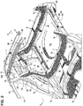
- FIG. 3 is a side view of the rear vehicle-body structure of the vehicle
- FIG. 4 is a perspective view of the rear vehicle-body structure of the vehicle, when viewed from a vehicle rearward side
- FIG. 5 is a side view of the rear vehicle-body structure of the vehicle, when viewed from a vehicle rightward side
- FIG. 6 is a sectional view of a rear-floor-panel side taken along line A-A of FIG. 2
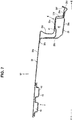
- FIG. 7 is a sectional view of a roof-panel side taken along line A-A of FIG. 2 .
- a front vehicle-body structure of the vehicle will be described referring to FIG. 1 first.
- a dash panel 1 which partitions, in a vehicle longitudinal direction, a cabin and an engine room is provided, and at a front side of an upper part of the dash panel 1 are provided a cowl panel 2 and a cowl cross member 3 which is fixedly joined to a lower part of the cowl panel 2, whereby a closed-cross section portion extending in a vehicle width direction is formed between the cowl panel 2 and the cowl cross member 3.
- a dash cross member 4 is fixedly joined to a front side of a lower part of the dash panel 1, whereby a closed-cross section portion extending in the vehicle width direction is formed between the dash panel 1 and the dash cross member 4 as well.
- a hinge pillar 5 which is formed by a hinge pillar inner and a hinge pillar outer which are fixedly joined together and has a hinge-pillar closed-cross section portion extending vertically is provided at each of right-and-left both sides of the dash panel 1.
- an apron 6 which extends forwardly from an upper part of the hinge pillar 5.
- This apron 6 is formed by an apron outer and an apron inner which are fixedly joined together, whereby an apron closed-cross section portion extending in the vehicle longitudinal direction is formed.
- Each of the front side frames 7 is formed by a front side frame inner and a front side frame outer which are fixedly joined together, whereby a front side closed-cross section portion extending in the vehicle longitudinal direction is formed.
- a front sub frame 8 to support front-suspension arms is provided below the front side frames 7.
- the front sub frame 8 comprises a sub frame body 8a which has a closed-cross section structure extending in the vehicle width direction, a pair of tower portions 8b which respectively have a closed-cross section structure and connect the sub frame body 8a and the respective front side frames 7, a pair of side members 8c which respectively extend forwardly from respective side portions of the sub frame body 8a, a pair of vehicle-body attaching members 8d which connect the pair of side members 8c and the pair of front side frames 7, and a front cross member 8e which interconnects respective front end portions of the pair of side members 8c.
- a crash can 10 is attached to a front end of each of the pair of side members 8c via a set plate and an attaching plate 9, and a lower bumper beam 11 is provided to extend in the vehicle width direction between a pair of right-and-left crash cans 10.
- a front wheel house 12 and a suspension tower portion 13 are provided between the apron 6 and the front side frame 7, the suspension tower portion 13 includes a top deck portion 13a and is formed by a thick plate portion which has a thicker plate thickness than a vehicle-body panel, and a damper support section 14 for a front suspension is formed at a nearly central part of the top deck portion 13a. That is, the damper support section 14 for the front suspension is provided at an upper part of the front wheel house 12.
- a front floor panel 15 which forms a floor surface of the cabin is integrally provided at a rear end of a lower part of the dash panel 1 and a kick-up portion 16 which rises upwardly is provided at a rear end of the front floor panel 15.
- This kick-up portion 16 rising upwardly from the rear end of the front floor panel 15 extends rearwardly from an upper end of its rising portion, and a cross member 17 (a so-called No. 3 cross member) is attached onto the kick-up portion 16 such that a closed-cross section extending in the vehicle width direction is formed between the cross member 17 and the kick-up portion 16.
- FIG. 1 shows a state where a rear seat pan and a rear floor pan are detached for convenience shake
- a rear seat pan 18 and a rear floor pan 19 are integrally provided at a rear portion of the cross member 17 as shown in FIGS. 2 , 3 and 6 .
- the rear seat pan 18 is a part of a rear floor on which a rear seat is placed.
- the rear floor pan 19 is a part of the rear floor which forms the floor surface of the cabin, and a baggage-room recess portion 19a is formed at a middle part of the rear floor pan 19.
- a rear end panel 20 is fixedly joined to a rear-end bent portion 19b of the rear floor pan 19, and a rear end cross member 21 extending in the vehicle width direction is fixedly joined to a front side of an upper part of the rear end panel 20 such that a closed-cross section 22 extending in the vehicle width direction is formed between the rear end panel 20 and the rear end cross member 21.
- a cross member upper 23 (a so-called No. 4 cross member upper) having a hat-shaped cross section is fixedly joined to an upper face of a border portion of a rear portion of the rear seat pan 18 and a front portion of the rear floor pan 19 such that a closed-cross section portion 24 extending in the vehicle width direction is formed between the cross member upper 23 and the above-described border portion.
- a cross member lower 25 (a so-called No. 4 cross member lower) having an inverse hat-shaped cross section is fixedly joined to a lower face of the border portion of the rear portion of the rear seat pan 18 and the front portion of the rear floor pan 19 such that a closed-cross section portion 26 extending in the vehicle width direction is formed between the cross member lower 25 and the above-described border portion.
- a rear cross member 27 (a so-called No. 4. 5 cross member) having an inverse hat-shaped cross section and extending in the vehicle width direction is fixedly joined to a lower surface of a middle part, in the longitudinal direction, of the rear floor pan 19 such that a closed-cross section portion 28 extending in the vehicle width direction is formed between the rear cross member 27 and the rear floor pan 19.
- a rear side frame upper 29 and a rear side frame lower 30 are fixedly joined to each of end portions, in the vehicle width direction, of the rear seat pan 18 and the rear floor pan 19 such that there is provided a rear side frame 32 which has a rear-side closed-cross section portion 31 (see FIG. 11 ) extending in the vehicle longitudinal direction.
- cross member 17, the cross member upper 23, the cross member lower 25, and the rear cross member 27 are provided to extend in the vehicle width direction between the right-and-left rear side frames 32, 32.
- a front end portion of the rear side frame 32 is provided to overlap a rear end portion of each of a pair of side sills 33 which are provided at right-and-left both sides of the front floor panel 15.
- the side sill 33 is a vehicle-body reinforcing member having a side-sill closed-cross section portion which is formed by a side sill inner and a side sill outer which are joined together and extends in the vehicle longitudinal direction.
- This side sill 33 is provided to extend in the vehicle longitudinal direction between a lower portion of the hinge pillar 5 and a rear-wheel arch front portion.
- a tunnel portion 34 is provided to protrude toward an inside of the cabin and extends in the vehicle longitudinal direction at a central part, in the vehicle width direction, of the front floor panel 15, a front cross member 35 (a so-called No. 2 cross member) and a middle cross member 36 (a so-called No. 2. 5 cross member) are provided to be spaced apart from each other in the vehicle longitudinal direction between the tunnel portion 34 and the side sill 33, and a closed-cross section portion extending in the vehicle width direction is formed between each of the cross embers 35, 36 and the front floor panel 15.
- a roof panel 39 is provided between a front header 37 positioned at a vehicle front part and a rear header 38 positioned at a vehicle rear part, and a pair of roof side rails 40, 40 extending in the vehicle longitudinal direction are provided below right-and-left both sides of the roof panel 39.
- the front header 37 positioned at the vehicle front part interconnects the right-and-left roof side rails 40, 40 in the vehicle width direction, and adhesively fixed to a lower face of a front portion of the roof panel 39 such that a closed-cross section portion is formed between the roof panel 39 and the front header 37.
- the rear header 38 positioned at the vehicle rear part comprises, as shown in FIG. 7 , an upper piece portion 38a, a front piece portion 38b which extends downwardly from a rear end of the upper piece portion 38a, a lower piece portion 38c which extends rearwardly from a lower end of the front piece portion 38b, and a rear piece portion 38d which extends upwardly from a rear end of the lower piece portion 38c, which are integrally formed by bending.
- a rear header reinforcement 41 is connected to an upper part of the rear header 38, and a rear end portion of the roof panel 39 is adhesively fixed to the rear header 38.
- the rear end portion of the roof panel 39 particularly comprises, as shown in FIG. 7 , a front piece portion 39b which extends downwardly from a rear end of a roof panel body 39a, a horizontal portion 39c which extends rearwardly from a lower end of the front piece portion 39b, a vertical wall portion 39d which extends downwardly from a rear end of the horizontal portion 39c, a lower piece portion 39e which extends rearwardly from a lower end of the vertical wall portion 39d, and a rear piece portion 39f which extends upwardly from a rear end of the lower piece portion 39e, which are integrally formed by bending.
- the upper piece portion 38a of the rear header 38 is adhesively fixed to the roof panel body 39a of the roof panel 39, and the rear piece portion 38d of the rear header 38 is adhesively fixed to the rear piece portion 39f of the roof panel 39.
- a rear-header closed-cross section portion 42 extending in the vehicle width direction is formed between the rear header 38 and the rear header reinforcement 41.
- the roof side rail 40 has a roof-side closed-cross section portion extending in the vehicle longitudinal direction which is formed by a roof side rail outer and a roof side rail inner which are fixedly joined together, and this roof side rail 41 is configured to be divided into plural parts in the vehicle longitudinal direction in the present embodiment.
- a middle reinforcement 43 and a rear reinforcement 44 of the roof side rail 40 are shown.
- plural roof reinforcements 45, 46, 47, 48 are provided to be space apart from each other in the vehicle longitudinal direction between the front header 37 positioned at the vehicle front part and the rear header 38 positioned at the vehicle rear part.
- Each of these roof reinforcements 45 - 48 is a reinforcing member which extends in the vehicle width direction between the right-and-left roof side rails 40, 40, and is adhesively fixed to a lower surface of the roof panel 39 such that a roof-reinforcement closed-cross section portion is formed between the roof panel 39 and each of the roof reinforcements 45 - 48.
- the rearmost roof reinforcement 48 is formed in a nearly W shape as shown in FIG. 1 , and two roof-reinforcement closed-cross sections 49 are formed between the roof reinforcement 48 and the roof panel 39.
- a front pillar 50 (a so-called A pillar) which extends obliquely upwardly-and-rearwardly from the hinge pillar 5.
- the front pillar 50 is formed by a front pillar inner and a front pillar outer which are fixedly joined together such that a front-pillar closed-cross section portion extending in a longitudinal direction of the front pillar 50 is formed therebetween.
- a middle portion, in the longitudinal direction, of the roof side rail 40 and a middle portion, in the longitudinal direction, of the side sill 33 are interconnected by a center pillar 51 (a so-called B pillar).
- the center pillar 51 is formed by a center pillar inner and a center pillar outer which are fixedly joined together such that a center-pillar closed-cross section portion extending in the vertical direction is formed therebetween.
- a rear portion of the roof side rail 40 and a rear portion of the side sill 33 are interconnected by a middle pillar 52 (a so-called C pillar) extending substantially in the vehicle vertical direction.
- a space which is enclosed by the hinge pillar 5, the front pillar 50, the roof side rail 40, the center pillar 51, and the side sill 33 is formed at a front-door opening 53
- a space which is enclosed by the center pillar 51, the roof side rail 4, the middle pillar 52, and the side sill 33 is formed at a rear-door opening 54.
- the above-described middle pillar 52 is arranged along a rear-side opening edge of the rear-door opening 54.
- a corner panel 56 of a closed-cross section structure which is formed by a corner panel inner 55 and a corner panel outer 55 is connected to respective side-end portions, in the vehicle width direction, of the rear end panel 20 and the rear end cross member 21.
- a side portion, in the vehicle width direction, of the rear header 38 and the corner panel 56 are interconnected by a rear pillar 57 (a so-called D pillar) of a closed-cross section structure.
- a rear baggage-room opening 58 is formed by the rear header 38, the rear pillar 57, the corner panel 56, the rear end cross member 21, and the rear end panel 20 (see FIG. 4 ).
- FIG. 8 is an enlarged side view of a major part of FIG. 3
- FIG. 9 is a sectional view taken along line B-B of FIG. 3
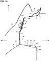
- FIG. 10 is a sectional view taken along line C-C of FIG. 3
- FIG. 11 is a sectional view taken along line D-D of FIG. 3 .
- the rear pillar 57 is divided into three of an upper portion 57a, a middle portion 57b, and a lower portion 57c in the present embodiment.
- the rear pillar 57 is particularly formed by a rear pillar inner 59, a rear pillar outer 60, and a rear pillar reinforcement 61 which are fixedly joined together, and a rear-pillar closed-cross section portion 62 which is continuous over a range of the upper portion 57a, the middle portion 57b, and the lower portion 57c is formed between the rear pillar reinforcement 61 and the rear pillar inner 59.
- a rear wheel house 65 is formed by a rear wheel house outer 63 forming a side panel and a rear wheel house inner 64.
- a side panel inner lower 66 is particularly provided to be upwardly continuous from the rear wheel house outer 63, and a side panel inner upper 67 is upwardly connected to the rear wheel house outer 66, wherein a side panel 68 is formed by the side panel inner lower 66 and the side panel inner upper 67.
- an upper end of the side panel inner upper 67 is connected to an outward-end bent portion 57d, in the vehicle width direction, of the rear pillar 57.
- a damper support section 70 for a rear suspension is provided at an upper part of the rear wheel house 65, particularly the rear wheel house inner 64 of the rear wheel house 65.
- a wheel house reinforcement 71 which has a thicker plate thickness than the vehicle-body panel is arranged at and/or around the damper support section 70, and this wheel house reinforcement 71 is fixedly joined to a top portion of the rear wheel house 65, particularly the rear wheel house inner 64.
- a plate member 72 which particularly connects, in the vertical direction, an upper end of the rear wheel house outer 63 and the middle portion 57b of the rear pillar 57 and is joined to an outward-side face, in the vehicle width direction, of the side panel inner upper 67, and a closed-cross section portion extending in the vertical direction is formed between the plate member 72 and the side panel inner upper 67.
- an attaching bracket 74 to attach a seatbelt retractor unit 73 as a vehicle component is fixedly fastened, together with the plate member 72, to a cabin side of the side panel inner upper 67 where the above-described plate member 72 is provided by using bolts 75 and weld nuts 76.
- the seatbelt retractor unit 73 is attached to the plate member 72 via the attaching bracket 74.
- the above-described attaching bracket 74 is particularly attached to the plate member 72 and a middle-pillar upper reinforcement 52b of the middle pillar 52.
- the seatbelt retractor unit 73 is provided with the attaching bracket 74 attached to the plate member 72 and the middle pillar 52.
- a brace member 77 which extends in the vertical direction from a cabin side of the rear wheel house inner 64 to a side portion, in the vehicle width direction, of the cross member upper 23.
- the brace member 77 is particularly configured to be vertically divided into an upper brace member 78 and a lower brace member 79.
- the upper brace member 78 is fixedly joined to the side panel inner upper 67, the side panel inner lower 66, the wheel house reinforcement 71, and the rear wheel house inner 64.
- the lower brace member 79 is fixedly joined to the rear wheel house inner 64 and the cross member upper 23.
- a closed-cross section 80 extending in the vertical direction is formed by or between the upper-and-lower brace members 78, 79 and the respective members 67, 66, 71, 64, 23.
- a gusset member 81 which connects, in the vehicle longitudinal direction, the lower portion 57c of the rear pillar 57 and the wheel house reinforcement 71 arranged at and/or around the damper support section 70.
- the gusset member 81 may be configured to connect, in the vehicle longitudinal direction, the lower portion 57c of the rear pillar 57 and the damper support section 70 as well as the wheel house reinforcement 71.
- the gusset member 81 particularly comprises an upper wall portion 81a, a lower wall portion 81b which extends downwardly from an inward end, in the vehicle width direction, of the upper wall portion 81a, a flange portion 81c which extends upwardly from an outward end, in the vehicle width direction, of the upper wall portion 81a, a ridgeline 81d which extends in the vehicle longitudinal direction along a longitudinal direction of the gusset member 81 provided between the upper wall portion 81a and the lower wall portion 81b, and a ridgeline 81e which extends in the vehicle longitudinal direction along the longitudinal direction of the gusset member 81 provided between the upper wall portion 81a and the flange portion 81c. That is, the gusset member 81 is a rigidity member which includes the ridgelines 81d, 81e.
- the above-described middle pillar 52 (the so-called C pillar) has a closed-cross section portion extending in the longitudinal direction thereof which is formed by a middle pillar inner 52a and middle-pillar reinforcements, which will be below.
- a middle-pillar upper reinforcement 52b, a middle-pillar middle reinforcement 52c, and a middle-pillar lower reinforcement 52d are fixedly joined to an outward-side face, in the vehicle width direction, of the middle pillar inner 52a.
- the middle-pillar upper reinforcement 52b is particularly positioned between a rear-side upper opening edge of the rear-door opening 54 and a front edge of an opening portion 82 for a quarter window
- the middle-pillar middle reinforcement 52c is fixedly joined to the side panel inner upper 67, the side panel inner lower 66, and a front upper portion of the rear wheel house outer 63
- the middle-pillar lower reinforcement 52d is fixedly joined to a front edge portion of the rear wheel house outer 63.
- a closed-cross section portion 83 extending in the longitudinal direction of the middle pillar 52 is formed between the middle pillar inner 52a and the middle-pillar reinforcement 52e which is formed by the middle-pillar upper reinforcement 52b, the middle-pillar middle reinforcement 52c, and the middle-pillar lower reinforcement 52d.
- a whole part of the rear vehicle body which extends from an upper edge portion of the rear pillar outer 60 to a lower edge portion of the rear wheel house outer 63 and a front edge portion of the middle pillar 52, excluding the opening portion 82 for the quarter window, is covered with a side frame outer 85 as a vehicle-body outer plate, illustration of which is omitted in FIGS. 4 and 5 .
- reference character 85 denotes a front side panel in FIG. 2
- reference character 86 denotes a rear side panel in FIGS. 4 and 5 .
- the loop-shaped structure section (or a loop-shaped vehicle-body framework) is formed by at least one of the closed-cross section portion, the thick plate portion having the thicker plate thickness than the vehicle-body panel, and the rigidity member including the ridgeline.
- a first loop-shaped structure section Z1 is particularly provided to extend continuously along a lower wall part E of the vehicle body which extends in the vehicle width direction, right-and-left side wall parts (or both right-and-left side wall parts) G, G of the vehicle body which extend in the vertical direction, and an upper wall part H of the vehicle body which is provided at a vehicle-body upper part and extends in the vehicle width direction, so as to have a loop shape in a vehicle elevational view and is positioned in front of, or on the forward side of, in the vehicle longitudinal direction, the damper support section 70.
- the first loop-shaped structure section Z1 is formed by at least one of a closed-cross section portion 24 positioned at the vehicle-body lower wall part E which is formed by the rear floor pan 19 and the cross member upper 23 as a floor cross member (see FIG. 6 ), closed-cross section portions 80, 83 positioned at each of the vehicle-body right-and-left both side wall parts G, G which are respectively formed by the rear wheel house inner 64 and the brace member 77 and the middle pillar 52 constituting the rear-side opening edge portion of the rear-door opening 54 (see FIG. 9 ), and a closed-cross section portion 49 positioned at the vehicle-body upper wall part H which is formed by the roof panel 39 and the roof reinforcement 48 (see FIG. 7 ).
- a second loop-shaped structure section Z2 is provided to extend continuously along the lower wall part E, right-and-left side wall parts (or both right-and-left side wall parts) G, G, I, I, J, J, and an upper wall part K of the vehicle body, so as to have a loop shape in the vehicle elevational view.
- the second loop-shaped structure section Z2 comprises a lower-side part which is located below or at a lower level than the damper support section 70 and an upper-side part which is located above or at a higher level than the damper support section 70.
- the lower-side part of the second loop-shaped structure section Z2 is formed by a part of the above-described first loop-shaped structure section Z1 and the upper-side part of the second loop-shaped structure section Z2 is positioned behind or on the rearward side of the damper support section 70, in the vehicle longitudinal direction.
- the second loop-shaped structure section Z2 is formed by at least one of the closed-cross section portion 24 positioned at the vehicle-body lower wall part E extending in the vehicle width direction which is formed by the rear floor pan 19 and the cross member upper 23 as the floor cross member (see FIG. 6 ), the closed-cross section portion 80 positioned at each of the vehicle-body right-and-left both side wall parts G, G extending in the vertical direction which is formed by the rear wheel house inner 64 and the brace member 77 (see FIG.
- the thick plate portion (see the wheel house reinforcement 71 itself) positioned at each of the vehicle-body right-and-left both side wall parts I, I which is formed by the damper support section 70 and the wheel house reinforcement 71 arranged around the damper support section 70, another closed-cross section portion positioned at each of the vehicle-body right-and-left both side wall parts J, J extending in the vertical direction which is formed by the side panel 68 and the plate member 72 which interconnects the upper end of the rear wheel house 65 and the upper end portion of the rear pillar 57 and is joined to the side panel 38, and the closed-cross section 42 positioned at the vehicle-body upper wall part K extending in the vehicle width direction which is formed by the roof panel 39 and the rear header 38 (see FIGS.
- FIGS. 1 and 2 there is particularly provided a third loop-shaped structure section Z3 which is configured to have a loop shape in a plan view.
- the third loop-shaped structure section Z3 is provided to extend continuously along the lower wall part E, right-and-left both side wall parts G, L, and a rear wall part M of the vehicle body so as to have a loop shape in the plan view.
- the third loop-shaped structure section Z3 particularly comprises a lower-side part which is located at a lower level than the damper support section 70, and this lower-side part is formed by a part of the above-described first loop-shaped structure section Z1.
- the third loop-shaped structure section Z3 is formed by at least one of the closed-cross section portion 24 positioned at the vehicle-body lower wall part E extending in the vehicle width direction which is formed by the rear floor panel 19 and the cross member upper 23 (see FIG. 6 ), the closed-cross section portion 80 positioned at each of the vehicle-body right-and-left both side wall parts G, G extending in the vertical direction which is formed by the rear wheel house 65 and the brace member 77 (see FIG.
- a rigidity member (see the gusset member 81 including the ridgelines 81d, 81e ) positioned at each of the vehicle-body right-and-left both side wall parts L, L which is formed by the gusset member 81 which connects, in the vehicle longitudinal direction, the rear pillar 57 and the damper support section 70 and the wheel house reinforcement 71 arranged around the damper support section 70, and the closed-cross section 22 positioned at the vehicle-body rear wall part M extending in the vehicle width direction which is formed by the rear end panel 20 and the rear end cross member 21 (see FIGS. 3 and 6 ).
- the damper support section 14 for the front suspension is particularly provided at the upper part of the front wheel house 12
- a fourth loop-shaped structure section Z4 is particularly provided in the vicinity of the damper support section 14 for the front suspension so as to have a loop shape in the vehicle elevational view
- a fifth loop-shaped structure section Z5 is particularly provided around the front-door opening 53 and the rear-door opening 54 so as to have a loop shape in the vehicle side view.
- the first loop-shaped structure section Z1 and the fifth loop-shaped structure section Z5 are connected via the above-described middle pillar 52.
- the fourth loop-shaped structure section Z4 particularly comprises the right-and-left suspension tower portions 13 provided with the top deck portions 13a which are formed as a thick plate portion, the right-and-left tower portions 8b of the closed-cross section structure which are connected to the right-and-left front side frames 7, the sub frame body 8a extending in the vehicle width direction, and the closed-cross section portion extending in the vehicle width direction which is formed by the cowl panel 2 and the cowl cross member 3.
- the fifth loop-shaped structure section Z5 comprises the hinge pillar 5 of the closed-cross section structure which extends in the vertical direction, the front pillar 50 of the closed-cross section structure which extends obliquely upwardly-and-rearwardly, the roof side rail 40 of the closed-cross section structure which extends in the vehicle longitudinal direction at the vehicle-body upper part, the middle pillar 52 of the closed-cross section structure, and the side sill 33 of the closed-cross section which extends in the vehicle longitudinal direction at the vehicle-body lower part.
- a sixth loop-shaped structure section Z6 is particularly formed at a middle position, in the longitudinal direction, between the fourth loop-shaped structure section Z4 and the first loop-shaped structure section Z1 so as to have a loop shape in the vehicle elevational view.
- the sixth loop-shaped structure section Z6 is particularly formed by a closed-cross section portion positioned at a vehicle-body lower wall part extending in the vehicle width direction which is formed by the front floor panel 15 and the middle cross member 36, another closed-cross section portion positioned at each of vehicle-body right-and-left both side wall parts extending in the vertical direction which is formed by the center pillar 51, and another closed-cross section portion positioned at a vehicle-body upper wall part extending in the vehicle width direction which is formed by the roof panel 39 and the roof reinforcement 46.
- an arrow F shows a vehicle front (forward) side
- an arrow R shows a vehicle rear (rearward) side
- an arrow IN shows a vehicle inward side in the vehicle width direction
- an arrow OUT shows a vehicle outward side in the vehicle width direction
- an arrow UP shows a vehicle upward side.
- the rear vehicle-body structure of the vehicle of the present embodiment comprises the damper support section 70 for the rear suspension provided at the upper part of the rear wheel house 65, the first loop-shaped structure section Z1 provided to extend continuously along the lower wall part E, the right-and-left both side wall parts G, and the upper wall part H of the vehicle body so as to have the loop shape in the vehicle elevational view, the first loop-shaped structure section Z1 being positioned on the forward side, in the vehicle longitudinal direction, of the damper support section 70, and the second loop-shaped structure section Z2 provided to extend continuously along the lower wall part E, the right-and-left both side wall parts G, I, J, and the upper wall part K of the vehicle body so as to have the loop shape in the vehicle elevational view, the second loop-shaped structure section Z2 comprising the lower-side part which is located at the lower level than the damper support section 70 and the upper-side part which is located at the higher level than the damper support section 70, the lower-side part of the second loop-shaped structure section Z2 being
- the first loop-shaped structure section Z1 and the second loop-shaped structure section Z2 which are formed by the closed-cross section portion and/or the thick plate portion are provided longitudinally, interposing the damper support section 70 for the rear suspension therebetween in the vehicle longitudinal direction, the vehicle-body rigidity of the vehicle-body rear portion can be securely improved.
- the first loop-shaped structure section Z1 is formed by the closed-cross section portion 24 positioned at the vehicle-body lower wall part E extending in the vehicle width direction which is formed by the floor panel (see the rear floor pan 19 ) and the floor cross member (see the cross member upper 23 ) joined to this floor panel, the closed-cross section portions 80, 83 positioned at each of the vehicle-body right-and-left both side wall parts G extending in the vehicle vertical direction which are formed by the rear wheel house 65 and the brace member 77 joined to the rear wheel house 65 and the middle pillar 52 constituting the opening edge portion of the rear-door opening 54, and the closed-cross section portion 49 positioned at the vehicle-body upper wall part H extending in the vehicle width direction which is formed by the roof panel 39 and the roof reinforcement 48 joined to the roof panel 39 (see FIGS. 2 , 6 , 7 and 9 ).
- the first loop-shaped structure section Z1 can be formed without using any particularly-large special members additionally.
- the second loop-shaped structure section Z2 is formed by the closed-cross section portion 24 positioned at the vehicle-body lower wall part E extending in a vehicle width direction which is formed by the floor panel (the rear floor pan 19 ) and the floor cross member (the cross member upper 23 ) joined to this floor panel, the closed-cross section portion 80 positioned at each of the vehicle-body right-and-left both side wall parts G extending in the vehicle vertical direction which is formed by the rear wheel house 65 and the brace member 77 joined to the rear wheel house 65, the thick plate portion positioned at each of the vehicle-body right-and-left both side wall parts I which is formed by the damper support section 70 and the wheel house reinforcement 71 arranged around the damper support section 70, the closed-cross section portion positioned at each of the vehicle-body right-and-left both side wall parts J extending in the vehicle vertical direction which is formed by the side panel 68 and the plate member 72 interconnecting the upper end of the rear wheel house 65 and the upper end portion of the rear pillar
- the second loop-shaped structure section Z2 can be formed without using any particularly-large special members additionally.
- the above-described vehicle component attached to the plate member 72 is the seatbelt retractor unit 73, and the seatbelt retractor unit 73 is provided with the attaching bracket 74 which is attached to the plate member 72 and the middle pillar 52 (see the middle-pillar upper reinforcement 52b particularly) (see FIGS. 8 and 10 ).
- the attaching bracket 74 of the seatbelt retractor unit 73 is attached to the plate member 72 and the middle pillar 52, the attaching rigidity of the seatbelt retractor unit 73 can be improved as well as the vehicle-body rigidity.
- the rear vehicle-body structure further comprises the third loop-shaped structure section Z3 provided to extend continuously along the lower wall part E, the right-and-left both side wall parts G, L, and the rear wall part M of the vehicle body so as to have the loop shape in the plan view, wherein the third loop-shaped structure section Z3 comprises the lower-side part which is located at the lower level than the damper support section 70 and the lower-side part of the third loop-shaped structure section Z3 is formed by a part of the first loop-shaped structure section Z1, and the third loop-shaped structure section Z3 is formed by the closed-cross section portions 24, 80, 22 where the closed-cross sections are respectively partitioned by plural members, the thick plate portion (the wheel house reinforcement 71 ) having the thicker plate thickness than the vehicle-body panel, and/or the rigidity member (see the gusset member 81 ) including the ridgelines 81d, 81e (see FIGS. 2 , 6 and 9 ).
- the third loop-shaped structure section Z3 comprises the lower-side part which is
- the third loop-shaped structure section Z3 is formed by the closed-cross section portion 24 positioned at the vehicle-body lower wall part E extending in the vehicle width direction which is formed by the floor panel (the rear floor pan 19 ) and the floor cross member (the cross member upper 23 ) joined to this floor panel, the closed-cross section portion 80 positioned at each of the vehicle-body right-and-left both side wall parts G extending in the vehicle vertical direction which is formed by the rear wheel house 65 and the brace member 77 joined to the rear wheel house 65, the rigidity member (the gusset member 81 including the ridgelines 81d, 81e ) positioned at each of the vehicle-body right-and-left both side wall parts L which is formed by the gusset member 81 which connects, in the vehicle longitudinal direction, the rear pillar 57 and the damper support section 70 and the wheel house reinforcement 71 arranged around the damper support section 70, and the closed-cross section portion 22 positioned at the vehicle-body rear wall part M extending in
- the third loop-shaped structure section Z3 can be formed without using any particularly-large special members additionally.
- the rear vehicle-body structure further comprises the damper support section 14 for the front suspension provided at the upper part of the front wheel house 12, the fourth loop-shaped structure section Z4 provided in the vicinity of the damper support section 14 for the front suspension so as to have the loop shape in the vehicle elevational view, and the fifth loop-shaped structure section Z5 provided around the door opening portions 53, 54 so as to have the loop shape in the vehicle side view, wherein the first loop-shaped structure section Z1 and the fifth loop-shaped structure section Z5 are connected via the middle pillar 52, and each of the fourth and fifth loop-shaped structure sections Z4, Z5 is formed by the closed-cross section portion where the closed-cross section is partitioned by the plural members and/or the thick plate portion (see the suspension tower 13, the top deck portion 13a ) having the thicker plate thickness than the vehicle-body panel (see FIG. 1 ).
- the fourth loop-shaped structure section Z4 is provided in the vicinity of the damper support section 14 for the front suspension and the first loop-shaped structure section Z1 and the fifth loop-shaped structure section Z5 are connected via the middle pillar 52, the support rigidity of the respective damper support sections 14, 70 for the rear and front suspensions can be efficiently improved by the vehicle's whole part and also the vehicle's handling stability can be improved.
- the floor panel corresponds to the rear floor pan 19 of the embodiment.
- the floor cross member corresponds to the cross member upper 23
- the vehicle component corresponds to the seatbelt retractor unit 73
- the thick plate portion corresponds to the wheel house reinforcement 71 (the second loop-shaped structure section Z2 ) and the suspension tower 13 and its top deck portion 13a (the fourth loop-shaped structure section Z4 )
- the rigidity member including the ridgeline corresponds to the gusset member 81.
- the present invention should not be limited to the above-described embodiment and any other modifications or improvements may be applied within the scope of the present invention.
Landscapes
- Engineering & Computer Science (AREA)
- Mechanical Engineering (AREA)
- Chemical & Material Sciences (AREA)
- Combustion & Propulsion (AREA)
- Transportation (AREA)
- Body Structure For Vehicles (AREA)
Abstract
Description
- The present invention relates to a vehicle-body structure of a vehicle, and a vehicle. Particularly, the present invention relates to a rear vehicle-body structure of a vehicle in which a loop-shaped structure section which is configured to have a loop shape in a vehicle elevational view is provided at a vehicle-body rear portion, wherein the loop-shaped structure section is formed by a closed-cross section portion and/or a thick plate portion having a thicker plate thickness than a vehicle-body panel.
- Japanese Patent Laid-Open Publication No.
2016-107789 - However, the above-described conventional structure disclosed in the patent document, in which the loop-shaped structure section having the loop shape in the vehicle elevational view is provided at the vehicle-body rear portion, may not be able to efficiently improve the rigidity of the vehicle-body rear portion because the inside rear pillar reinforcement is spaced forwardly, in the vehicle longitudinal direction, apart from the damper support section for the rear suspension. Therefore, there is room for improvement in improving the rigidity of the vehicle-body rear portion.
- Accordingly, an object of the present invention is to improve the vehicle-body rigidity of the vehicle-body rear portion.
- This object is solved by the vehicle-body structure of the vehicle according to the present invention of the independent claim. Preferred embodiments are subject of the other dependent claims.
- The vehicle-body structure of the vehicle comprises a damper support section for a rear suspension provided at an upper part of a rear wheel house, a first loop-shaped structure section provided to extend continuously along a lower wall part, right-and-left side wall parts, and an upper wall part of a vehicle body so as to have a loop shape in a vehicle elevational view, the first loop-shaped structure section being positioned in front of or on a forward side of said damper support section in a vehicle longitudinal direction, and a second loop-shaped structure section provided to extend continuously along a lower wall part, right-and-left side wall parts, and an upper wall part of the vehicle body so as to have a loop shape in the vehicle elevational view, the second loop-shaped structure section comprising a lower-side part which is located below or at a lower level than the damper support section and an upper-side part which is located above or at a higher level than the damper support section, the lower-side part of the second loop-shaped structure section being formed by a part of the first loop-shaped structure section, the upper-side part of the second loop-shaped structure section being positioned behind or on a rearward side of the damper support section in the vehicle longitudinal direction, wherein each of the first and second loop-shaped structure sections is formed by one or more closed-cross section portions where one or more closed-cross sections are partitioned by plural members and/or a thick plate portion having a thicker plate thickness than a vehicle-body panel. The vehicle-body structure of the vehicle may particularly be a rear vehicle-body structure of the vehicle.
- Since the first loop-shaped structure section and the second loop-shaped structure section which are formed by the closed-cross section portion and/or the thick plate portion are provided longitudinally, interposing the damper support section for the rear suspension therebetween in the vehicle longitudinal direction, the vehicle-body rigidity of the vehicle-body rear portion can be securely improved.
- Particularly, in an embodiment, the first loop-shaped structure section is formed by at least one of a closed-cross section portion positioned at the vehicle-body lower wall part extending in a vehicle width direction which is formed by a floor panel and a floor cross member joined to the floor panel, one or more closed-cross section portions positioned at each of the vehicle-body right-and-left side wall parts extending in a vehicle vertical direction which are formed by the rear wheel house and a brace member joined to the rear wheel house and a pillar constituting an opening edge portion of a rear-door opening, and a closed-cross section portion positioned at the vehicle-body upper wall part extending in the vehicle width direction which is formed by a roof panel and a roof reinforcement joined to the roof panel.
- According to this embodiment, the first loop-shaped structure section can be formed without using any particularly-large special members additionally.
- Further particularly, in another embodiment, the second loop-shaped structure section is formed by at least one of a closed-cross section portion positioned at the vehicle-body lower wall part extending in a vehicle width direction which is formed by a floor panel and a floor cross member joined to the floor panel, a closed-cross section portion positioned at each of the vehicle-body right-and-left side wall parts extending in a vehicle vertical direction which is formed by the rear wheel house and a brace member joined to the rear wheel house, the thick plate portion positioned at each of the vehicle-body right-and-left side wall parts which is formed by the damper support section and a wheel house reinforcement arranged around the damper support section, a closed-cross section portion positioned at each of the vehicle-body right-and-left side wall parts extending in the vehicle vertical direction which is formed by a side panel and a plate member interconnecting an upper end of the rear wheel house and an upper end portion of a rear pillar and joined to the side panel, and a closed-cross section portion positioned at the vehicle-body upper wall part extending in the vehicle width direction which is formed by a roof panel and a rear header joined to the roof panel. Further particularly, the plate member being configured such that a vehicle component is attached thereto.
- According to this embodiment, the second loop-shaped structure section can be formed without using any particularly-large special members additionally.
- Further particularly, in another embodiment, the vehicle component attached to the plate member is a seatbelt retractor unit, and the seatbelt retractor unit is provided with an attaching bracket which is attached to the plate member and the pillar.
- According to this embodiment, since the attaching bracket of the seatbelt retractor unit is attached to the plate member and the pillar, the attaching rigidity of the seatbelt retractor unit can be improved as well as the vehicle-body rigidity.
- Further particularly, in another embodiment, the vehicle-body structure further comprises a third loop-shaped structure section provided to extend continuously along the lower wall part, right-and-left side wall parts, and a rear wall part of the vehicle body so as to have a loop shape in a plan view. Further particularly, the third loop-shaped structure section comprises a lower-side part which is located below or at a lower level than the damper support section, and the lower-side part of the third loop-shaped structure section is formed by a part of the first loop-shaped structure section. Further particularly, the third loop-shaped structure section is formed by at least one of a closed-cross section portion where a closed-cross section is partitioned by plural members, a thick plate portion having a thicker plate thickness than a vehicle-body panel, and/or a rigidity member including a ridgeline.
- According to this embodiment, while an upper part of the first loop-shaped structure section is offset rearwardly from an upper part of the second loop-shaped structure section, this offset portion can be reinforced by the third loop-shaped structure section.
- Further particularly, in another embodiment, the third loop-shaped structure section is formed by a closed-cross section portion positioned at the vehicle-body lower wall part extending in a vehicle width direction which is formed by a floor panel and a floor cross member joined to the floor panel, a closed-cross section portion positioned at each of the vehicle-body right-and-left side wall parts extending in a vehicle vertical direction which is formed by the rear wheel house and a brace member joined to the rear wheel house, a rigidity member positioned at each of the vehicle-body right-and-left side wall parts which is formed by a gusset member which connects, in the vehicle longitudinal direction, a rear pillar and a wheel house reinforcement arranged at the damper support section and/or around the damper support section, and/or a closed-cross section portion positioned at the vehicle-body rear wall part extending in the vehicle width direction which is formed by a rear end panel and a rear end cross member joined to the rear end panel.
- According to this embodiment, the third loop-shaped structure section can be formed without using any particularly-large special members additionally.
- Further particularly, in another embodiment, the vehicle-body structure further comprises a damper support section for a front suspension provided at an upper part of a front wheel house. Further particularly, the vehicle-body structure further comprises a fourth loop-shaped structure section provided in a vicinity of the damper support section for the front suspension so as to have a loop shape in the vehicle elevational view. Further particularly, the vehicle-body structure further comprises a fifth loop-shaped structure section provided around a door opening portion so as to have a loop shape in the vehicle side view. Further particularly, the first loop-shaped structure section and the fifth loop-shaped structure section are connected via the pillar. Further particularly, each of the fourth and fifth loop-shaped structure sections is formed by a closed-cross section portion where a closed-cross section is partitioned by plural members and/or a thick plate portion having a thicker plate thickness than the vehicle-body panel.
- According to this embodiment, since the fourth loop-shaped structure section is provided in the vicinity of the damper support section for the front suspension and the first loop-shaped structure section and the fifth loop-shaped structure section are connected via the pillar, the support rigidity of the respective damper support sections for the rear and front suspensions can be efficiently improved by the vehicle's whole part and also the vehicle's handling stability can be improved.
- Further particularly, a vehicle includes the above vehicle-body structure.
- An embodiment will become apparent from the following description which refers to the accompanying drawings.
-
FIG. 1 is a perspective view of a vehicle-body structure of a vehicle, when viewed from a vehicle forward side. -
FIG. 2 is a perspective view of a rear vehicle-body structure of the vehicle. -
FIG. 3 is a side view of the rear vehicle-body structure of the vehicle. -
FIG. 4 is a perspective view of the rear vehicle-body structure of the vehicle, when viewed from a vehicle rearward side. -
FIG. 5 is a side view of the rear vehicle-body structure of the vehicle, when viewed from a vehicle rightward side. -
FIG. 6 is a sectional view of a rear-floor-panel side taken along line A-A ofFIG. 2 . -
FIG. 7 is a sectional view of a roof-panel side taken along line A-A ofFIG. 2 . -
FIG. 8 is an enlarged side view of a major part ofFIG. 3 . -
FIG. 9 is a sectional view taken along line B-B ofFIG. 3 . -
FIG. 10 is a sectional view taken along line C-C ofFIG. 3 . -
FIG. 11 is a sectional view taken along line D-D ofFIG. 3 . - Hereafter, an embodiment will be described referring to the drawings. The drawings show a vehicle-body structure of a vehicle,
FIG. 1 is a perspective view of a vehicle-body structure of the vehicle, when viewed from a vehicle forward side,FIG. 2 is a perspective view of the rear vehicle-body structure of the vehicle,FIG. 3 is a side view of the rear vehicle-body structure of the vehicle,FIG. 4 is a perspective view of the rear vehicle-body structure of the vehicle, when viewed from a vehicle rearward side,FIG. 5 is a side view of the rear vehicle-body structure of the vehicle, when viewed from a vehicle rightward side,FIG. 6 is a sectional view of a rear-floor-panel side taken along line A-A ofFIG. 2 , andFIG. 7 is a sectional view of a roof-panel side taken along line A-A ofFIG. 2 . - A front vehicle-body structure of the vehicle will be described referring to
FIG. 1 first. A dash panel 1 which partitions, in a vehicle longitudinal direction, a cabin and an engine room is provided, and at a front side of an upper part of the dash panel 1 are provided a cowl panel 2 and acowl cross member 3 which is fixedly joined to a lower part of the cowl panel 2, whereby a closed-cross section portion extending in a vehicle width direction is formed between the cowl panel 2 and thecowl cross member 3. A dash cross member 4 is fixedly joined to a front side of a lower part of the dash panel 1, whereby a closed-cross section portion extending in the vehicle width direction is formed between the dash panel 1 and the dash cross member 4 as well. - A
hinge pillar 5 which is formed by a hinge pillar inner and a hinge pillar outer which are fixedly joined together and has a hinge-pillar closed-cross section portion extending vertically is provided at each of right-and-left both sides of the dash panel 1. There is provided an apron 6 which extends forwardly from an upper part of thehinge pillar 5. This apron 6 is formed by an apron outer and an apron inner which are fixedly joined together, whereby an apron closed-cross section portion extending in the vehicle longitudinal direction is formed. - There is provided a pair of front side frames 7 which extend forwardly from respective lower parts of right-and-left both sides of the dash panel 1. Each of the front side frames 7 is formed by a front side frame inner and a front side frame outer which are fixedly joined together, whereby a front side closed-cross section portion extending in the vehicle longitudinal direction is formed.
- A front sub frame 8 to support front-suspension arms is provided below the front side frames 7. The front sub frame 8 comprises a
sub frame body 8a which has a closed-cross section structure extending in the vehicle width direction, a pair oftower portions 8b which respectively have a closed-cross section structure and connect thesub frame body 8a and the respective front side frames 7, a pair ofside members 8c which respectively extend forwardly from respective side portions of thesub frame body 8a, a pair of vehicle-body attaching members 8d which connect the pair ofside members 8c and the pair of front side frames 7, and afront cross member 8e which interconnects respective front end portions of the pair ofside members 8c. - Further, a crash can 10 is attached to a front end of each of the pair of
side members 8c via a set plate and an attachingplate 9, and alower bumper beam 11 is provided to extend in the vehicle width direction between a pair of right-and-left crash cans 10. - Moreover, a
front wheel house 12 and asuspension tower portion 13 are provided between the apron 6 and the front side frame 7, thesuspension tower portion 13 includes atop deck portion 13a and is formed by a thick plate portion which has a thicker plate thickness than a vehicle-body panel, and adamper support section 14 for a front suspension is formed at a nearly central part of thetop deck portion 13a. That is, thedamper support section 14 for the front suspension is provided at an upper part of thefront wheel house 12. - As shown in
FIGS. 1 and2 , afront floor panel 15 which forms a floor surface of the cabin is integrally provided at a rear end of a lower part of the dash panel 1 and a kick-upportion 16 which rises upwardly is provided at a rear end of thefront floor panel 15. This kick-upportion 16 rising upwardly from the rear end of thefront floor panel 15 extends rearwardly from an upper end of its rising portion, and a cross member 17 (a so-called No. 3 cross member) is attached onto the kick-upportion 16 such that a closed-cross section extending in the vehicle width direction is formed between thecross member 17 and the kick-upportion 16. - While
FIG. 1 shows a state where a rear seat pan and a rear floor pan are detached for convenience shake, arear seat pan 18 and arear floor pan 19 are integrally provided at a rear portion of thecross member 17 as shown inFIGS. 2 ,3 and6 . - The
rear seat pan 18 is a part of a rear floor on which a rear seat is placed. Therear floor pan 19 is a part of the rear floor which forms the floor surface of the cabin, and a baggage-room recessportion 19a is formed at a middle part of therear floor pan 19. - As shown in
FIG. 6 , arear end panel 20 is fixedly joined to a rear-end bent portion 19b of therear floor pan 19, and a rearend cross member 21 extending in the vehicle width direction is fixedly joined to a front side of an upper part of therear end panel 20 such that a closed-cross section 22 extending in the vehicle width direction is formed between therear end panel 20 and the rearend cross member 21. - As shown in
FIGS. 3 and6 , a cross member upper 23 (a so-called No. 4 cross member upper) having a hat-shaped cross section is fixedly joined to an upper face of a border portion of a rear portion of therear seat pan 18 and a front portion of therear floor pan 19 such that a closed-cross section portion 24 extending in the vehicle width direction is formed between the cross member upper 23 and the above-described border portion. - Likewise, a cross member lower 25 (a so-called No. 4 cross member lower) having an inverse hat-shaped cross section is fixedly joined to a lower face of the border portion of the rear portion of the
rear seat pan 18 and the front portion of therear floor pan 19 such that a closed-cross section portion 26 extending in the vehicle width direction is formed between the cross member lower 25 and the above-described border portion. - Further, as shown in
FIGS. 3 and6 , a rear cross member 27 (a so-called No. 4. 5 cross member) having an inverse hat-shaped cross section and extending in the vehicle width direction is fixedly joined to a lower surface of a middle part, in the longitudinal direction, of therear floor pan 19 such that a closed-cross section portion 28 extending in the vehicle width direction is formed between therear cross member 27 and therear floor pan 19. - As shown in
FIG. 2 , a rear side frame upper 29 and a rear side frame lower 30 are fixedly joined to each of end portions, in the vehicle width direction, of therear seat pan 18 and therear floor pan 19 such that there is provided arear side frame 32 which has a rear-side closed-cross section portion 31 (seeFIG. 11 ) extending in the vehicle longitudinal direction. - Herein, the
cross member 17, the cross member upper 23, the cross member lower 25, and therear cross member 27 are provided to extend in the vehicle width direction between the right-and-left rear side frames 32, 32. - As shown in
FIG. 1 , a front end portion of therear side frame 32 is provided to overlap a rear end portion of each of a pair ofside sills 33 which are provided at right-and-left both sides of thefront floor panel 15. Theside sill 33 is a vehicle-body reinforcing member having a side-sill closed-cross section portion which is formed by a side sill inner and a side sill outer which are joined together and extends in the vehicle longitudinal direction. This side sill 33 is provided to extend in the vehicle longitudinal direction between a lower portion of thehinge pillar 5 and a rear-wheel arch front portion. - As shown in
FIG. 1 , atunnel portion 34 is provided to protrude toward an inside of the cabin and extends in the vehicle longitudinal direction at a central part, in the vehicle width direction, of thefront floor panel 15, a front cross member 35 (a so-called No. 2 cross member) and a middle cross member 36 (a so-called No. 2. 5 cross member) are provided to be spaced apart from each other in the vehicle longitudinal direction between thetunnel portion 34 and theside sill 33, and a closed-cross section portion extending in the vehicle width direction is formed between each of thecross embers front floor panel 15. - Meanwhile, as shown in
FIGS. 1 and7 , aroof panel 39 is provided between afront header 37 positioned at a vehicle front part and arear header 38 positioned at a vehicle rear part, and a pair of roof side rails 40, 40 extending in the vehicle longitudinal direction are provided below right-and-left both sides of theroof panel 39. - The
front header 37 positioned at the vehicle front part interconnects the right-and-left roof side rails 40, 40 in the vehicle width direction, and adhesively fixed to a lower face of a front portion of theroof panel 39 such that a closed-cross section portion is formed between theroof panel 39 and thefront header 37. - The
rear header 38 positioned at the vehicle rear part comprises, as shown inFIG. 7 , anupper piece portion 38a, afront piece portion 38b which extends downwardly from a rear end of theupper piece portion 38a, alower piece portion 38c which extends rearwardly from a lower end of thefront piece portion 38b, and arear piece portion 38d which extends upwardly from a rear end of thelower piece portion 38c, which are integrally formed by bending. Arear header reinforcement 41 is connected to an upper part of therear header 38, and a rear end portion of theroof panel 39 is adhesively fixed to therear header 38. - The rear end portion of the
roof panel 39 particularly comprises, as shown inFIG. 7 , afront piece portion 39b which extends downwardly from a rear end of aroof panel body 39a, ahorizontal portion 39c which extends rearwardly from a lower end of thefront piece portion 39b, avertical wall portion 39d which extends downwardly from a rear end of thehorizontal portion 39c, alower piece portion 39e which extends rearwardly from a lower end of thevertical wall portion 39d, and arear piece portion 39f which extends upwardly from a rear end of thelower piece portion 39e, which are integrally formed by bending. - The
upper piece portion 38a of therear header 38 is adhesively fixed to theroof panel body 39a of theroof panel 39, and therear piece portion 38d of therear header 38 is adhesively fixed to therear piece portion 39f of theroof panel 39. A rear-header closed-cross section portion 42 extending in the vehicle width direction is formed between therear header 38 and therear header reinforcement 41. - The
roof side rail 40 has a roof-side closed-cross section portion extending in the vehicle longitudinal direction which is formed by a roof side rail outer and a roof side rail inner which are fixedly joined together, and thisroof side rail 41 is configured to be divided into plural parts in the vehicle longitudinal direction in the present embodiment. InFIGS. 4 and5 , amiddle reinforcement 43 and arear reinforcement 44 of theroof side rail 40 are shown. As shown inFIG. 1 ,plural roof reinforcements front header 37 positioned at the vehicle front part and therear header 38 positioned at the vehicle rear part. - Each of these roof reinforcements 45 - 48 is a reinforcing member which extends in the vehicle width direction between the right-and-left roof side rails 40, 40, and is adhesively fixed to a lower surface of the
roof panel 39 such that a roof-reinforcement closed-cross section portion is formed between theroof panel 39 and each of the roof reinforcements 45 - 48. - The
rearmost roof reinforcement 48 is formed in a nearly W shape as shown inFIG. 1 , and two roof-reinforcement closed-cross sections 49 are formed between theroof reinforcement 48 and theroof panel 39. - As shown in
FIG. 1 , an upper end portion of thehinge pillar 5 and a front end portion of theroof side rail 40 are interconnected by a front pillar 50 (a so-called A pillar) which extends obliquely upwardly-and-rearwardly from thehinge pillar 5. Thefront pillar 50 is formed by a front pillar inner and a front pillar outer which are fixedly joined together such that a front-pillar closed-cross section portion extending in a longitudinal direction of thefront pillar 50 is formed therebetween. - Further, as shown in
FIG. 1 , a middle portion, in the longitudinal direction, of theroof side rail 40 and a middle portion, in the longitudinal direction, of theside sill 33 are interconnected by a center pillar 51 (a so-called B pillar). Thecenter pillar 51 is formed by a center pillar inner and a center pillar outer which are fixedly joined together such that a center-pillar closed-cross section portion extending in the vertical direction is formed therebetween. Moreover, as shown inFIGS. 1 ,4 and5 , a rear portion of theroof side rail 40 and a rear portion of theside sill 33 are interconnected by a middle pillar 52 (a so-called C pillar) extending substantially in the vehicle vertical direction. - As shown in
FIG. 1 , a space which is enclosed by thehinge pillar 5, thefront pillar 50, theroof side rail 40, thecenter pillar 51, and theside sill 33 is formed at a front-door opening 53, and a space which is enclosed by thecenter pillar 51, the roof side rail 4, themiddle pillar 52, and theside sill 33 is formed at a rear-door opening 54. The above-describedmiddle pillar 52 is arranged along a rear-side opening edge of the rear-door opening 54. - As shown in
FIG. 4 , acorner panel 56 of a closed-cross section structure which is formed by a corner panel inner 55 and a corner panel outer 55 is connected to respective side-end portions, in the vehicle width direction, of therear end panel 20 and the rearend cross member 21. - As shown in
FIGS. 3 ,4 and5 , a side portion, in the vehicle width direction, of therear header 38 and thecorner panel 56 are interconnected by a rear pillar 57 (a so-called D pillar) of a closed-cross section structure. A rear baggage-room opening 58 is formed by therear header 38, therear pillar 57, thecorner panel 56, the rearend cross member 21, and the rear end panel 20 (seeFIG. 4 ). -
FIG. 8 is an enlarged side view of a major part ofFIG. 3 ,FIG. 9 is a sectional view taken along line B-B ofFIG. 3 ,FIG. 10 is a sectional view taken along line C-C ofFIG. 3 , andFIG. 11 is a sectional view taken along line D-D ofFIG. 3 . As shown inFIG. 3 , therear pillar 57 is divided into three of anupper portion 57a, amiddle portion 57b, and alower portion 57c in the present embodiment. - As shown in
FIGS. 9 ,10 and11 , therear pillar 57 is particularly formed by a rear pillar inner 59, a rear pillar outer 60, and arear pillar reinforcement 61 which are fixedly joined together, and a rear-pillar closed-cross section portion 62 which is continuous over a range of theupper portion 57a, themiddle portion 57b, and thelower portion 57c is formed between therear pillar reinforcement 61 and the rear pillar inner 59. As shown inFIGS. 9 ,10 and11 , arear wheel house 65 is formed by a rear wheel house outer 63 forming a side panel and a rear wheel house inner 64. - As shown in
FIG. 11 , a side panel inner lower 66 is particularly provided to be upwardly continuous from the rear wheel house outer 63, and a side panel inner upper 67 is upwardly connected to the rear wheel house outer 66, wherein aside panel 68 is formed by the side panel inner lower 66 and the side panel inner upper 67. As shown inFIGS. 10 and11 , an upper end of the side panel inner upper 67 is connected to an outward-endbent portion 57d, in the vehicle width direction, of therear pillar 57. - As shown in
FIGS. 2 and3 , adamper support section 70 for a rear suspension is provided at an upper part of therear wheel house 65, particularly the rearwheel house inner 64 of therear wheel house 65. Awheel house reinforcement 71 which has a thicker plate thickness than the vehicle-body panel is arranged at and/or around thedamper support section 70, and thiswheel house reinforcement 71 is fixedly joined to a top portion of therear wheel house 65, particularly the rear wheel house inner 64. - As shown in
FIGS. 4 and5 , there is provided aplate member 72 which particularly connects, in the vertical direction, an upper end of the rear wheel house outer 63 and themiddle portion 57b of therear pillar 57 and is joined to an outward-side face, in the vehicle width direction, of the side panel inner upper 67, and a closed-cross section portion extending in the vertical direction is formed between theplate member 72 and the side panel inner upper 67. - As shown in
FIGS. 8 and10 , an attachingbracket 74 to attach aseatbelt retractor unit 73 as a vehicle component is fixedly fastened, together with theplate member 72, to a cabin side of the side panel inner upper 67 where the above-describedplate member 72 is provided by usingbolts 75 and weld nuts 76. Theseatbelt retractor unit 73 is attached to theplate member 72 via the attachingbracket 74. - The above-described attaching
bracket 74 is particularly attached to theplate member 72 and a middle-pillarupper reinforcement 52b of themiddle pillar 52. In other words, theseatbelt retractor unit 73 is provided with the attachingbracket 74 attached to theplate member 72 and themiddle pillar 52. As shown inFIGS. 2 and3 , there is provided abrace member 77 which extends in the vertical direction from a cabin side of the rear wheel house inner 64 to a side portion, in the vehicle width direction, of the cross member upper 23. - In the present embodiment, the
brace member 77 is particularly configured to be vertically divided into anupper brace member 78 and alower brace member 79. Theupper brace member 78 is fixedly joined to the side panel inner upper 67, the side panel inner lower 66, thewheel house reinforcement 71, and the rear wheel house inner 64. Thelower brace member 79 is fixedly joined to the rear wheel house inner 64 and the cross member upper 23. As shown inFIG. 9 , a closed-cross section 80 extending in the vertical direction is formed by or between the upper-and-lower brace members respective members FIGS. 3 ,10 and11 , there is particularly provided agusset member 81 which connects, in the vehicle longitudinal direction, thelower portion 57c of therear pillar 57 and thewheel house reinforcement 71 arranged at and/or around thedamper support section 70. Thegusset member 81 may be configured to connect, in the vehicle longitudinal direction, thelower portion 57c of therear pillar 57 and thedamper support section 70 as well as thewheel house reinforcement 71. - As shown in
FIGS. 3 ,10 and11 , thegusset member 81 particularly comprises anupper wall portion 81a, alower wall portion 81b which extends downwardly from an inward end, in the vehicle width direction, of theupper wall portion 81a, aflange portion 81c which extends upwardly from an outward end, in the vehicle width direction, of theupper wall portion 81a, aridgeline 81d which extends in the vehicle longitudinal direction along a longitudinal direction of thegusset member 81 provided between theupper wall portion 81a and thelower wall portion 81b, and aridgeline 81e which extends in the vehicle longitudinal direction along the longitudinal direction of thegusset member 81 provided between theupper wall portion 81a and theflange portion 81c. That is, thegusset member 81 is a rigidity member which includes theridgelines - As shown in
FIGS. 3 ,4 and5 , the above-described middle pillar 52 (the so-called C pillar) has a closed-cross section portion extending in the longitudinal direction thereof which is formed by a middle pillar inner 52a and middle-pillar reinforcements, which will be below. A middle-pillarupper reinforcement 52b, a middle-pillarmiddle reinforcement 52c, and a middle-pillarlower reinforcement 52d are fixedly joined to an outward-side face, in the vehicle width direction, of the middle pillar inner 52a. - As shown in
FIGS. 4 and5 , the middle-pillarupper reinforcement 52b is particularly positioned between a rear-side upper opening edge of the rear-door opening 54 and a front edge of anopening portion 82 for a quarter window, the middle-pillarmiddle reinforcement 52c is fixedly joined to the side panel inner upper 67, the side panel inner lower 66, and a front upper portion of the rear wheel house outer 63, and the middle-pillarlower reinforcement 52d is fixedly joined to a front edge portion of the rear wheel house outer 63. - As shown in
FIG. 9 , a closed-cross section portion 83 extending in the longitudinal direction of themiddle pillar 52 is formed between the middle pillar inner 52a and the middle-pillar reinforcement 52e which is formed by the middle-pillarupper reinforcement 52b, the middle-pillarmiddle reinforcement 52c, and the middle-pillarlower reinforcement 52d. - As shown in
FIGS. 9 ,10 and11 , a whole part of the rear vehicle body which extends from an upper edge portion of the rear pillar outer 60 to a lower edge portion of the rear wheel house outer 63 and a front edge portion of themiddle pillar 52, excluding the openingportion 82 for the quarter window, is covered with a side frame outer 85 as a vehicle-body outer plate, illustration of which is omitted inFIGS. 4 and5 . Herein,reference character 85 denotes a front side panel inFIG. 2 , andreference character 86 denotes a rear side panel inFIGS. 4 and5 . - A loop-shaped structure section will be described referring to
FIGS. 1 ,2 and others. The loop-shaped structure section (or a loop-shaped vehicle-body framework) is formed by at least one of the closed-cross section portion, the thick plate portion having the thicker plate thickness than the vehicle-body panel, and the rigidity member including the ridgeline. - A first loop-shaped structure section Z1 is particularly provided to extend continuously along a lower wall part E of the vehicle body which extends in the vehicle width direction, right-and-left side wall parts (or both right-and-left side wall parts) G, G of the vehicle body which extend in the vertical direction, and an upper wall part H of the vehicle body which is provided at a vehicle-body upper part and extends in the vehicle width direction, so as to have a loop shape in a vehicle elevational view and is positioned in front of, or on the forward side of, in the vehicle longitudinal direction, the
damper support section 70. - The first loop-shaped structure section Z1 is formed by at least one of a closed-
cross section portion 24 positioned at the vehicle-body lower wall part E which is formed by therear floor pan 19 and the cross member upper 23 as a floor cross member (seeFIG. 6 ), closed-cross section portions brace member 77 and themiddle pillar 52 constituting the rear-side opening edge portion of the rear-door opening 54 (seeFIG. 9 ), and a closed-cross section portion 49 positioned at the vehicle-body upper wall part H which is formed by theroof panel 39 and the roof reinforcement 48 (seeFIG. 7 ). - Moreover, a second loop-shaped structure section Z2 is provided to extend continuously along the lower wall part E, right-and-left side wall parts (or both right-and-left side wall parts) G, G, I, I, J, J, and an upper wall part K of the vehicle body, so as to have a loop shape in the vehicle elevational view. Herein, the second loop-shaped structure section Z2 comprises a lower-side part which is located below or at a lower level than the
damper support section 70 and an upper-side part which is located above or at a higher level than thedamper support section 70. The lower-side part of the second loop-shaped structure section Z2 is formed by a part of the above-described first loop-shaped structure section Z1 and the upper-side part of the second loop-shaped structure section Z2 is positioned behind or on the rearward side of thedamper support section 70, in the vehicle longitudinal direction. - The second loop-shaped structure section Z2 is formed by at least one of the closed-cross section portion 24 positioned at the vehicle-body lower wall part E extending in the vehicle width direction which is formed by the rear floor pan 19 and the cross member upper 23 as the floor cross member (see
FIG. 6 ), the closed-cross section portion 80 positioned at each of the vehicle-body right-and-left both side wall parts G, G extending in the vertical direction which is formed by the rear wheel house inner 64 and the brace member 77 (seeFIG. 9 ), the thick plate portion (see the wheel house reinforcement 71 itself) positioned at each of the vehicle-body right-and-left both side wall parts I, I which is formed by the damper support section 70 and the wheel house reinforcement 71 arranged around the damper support section 70, another closed-cross section portion positioned at each of the vehicle-body right-and-left both side wall parts J, J extending in the vertical direction which is formed by the side panel 68 and the plate member 72 which interconnects the upper end of the rear wheel house 65 and the upper end portion of the rear pillar 57 and is joined to the side panel 38, and the closed-cross section 42 positioned at the vehicle-body upper wall part K extending in the vehicle width direction which is formed by the roof panel 39 and the rear header 38 (seeFIGS. 3 and7 ), wherein the plate member 72 is configured such that the seatbelt retractor unit 73 as a vehicle component is attached thereto. As shown inFIGS. 1 and2 , there is particularly provided a third loop-shaped structure section Z3 which is configured to have a loop shape in a plan view. - The third loop-shaped structure section Z3 is provided to extend continuously along the lower wall part E, right-and-left both side wall parts G, L, and a rear wall part M of the vehicle body so as to have a loop shape in the plan view. Herein, the third loop-shaped structure section Z3 particularly comprises a lower-side part which is located at a lower level than the
damper support section 70, and this lower-side part is formed by a part of the above-described first loop-shaped structure section Z1. - The third loop-shaped structure section Z3 is formed by at least one of the closed-
cross section portion 24 positioned at the vehicle-body lower wall part E extending in the vehicle width direction which is formed by therear floor panel 19 and the cross member upper 23 (seeFIG. 6 ), the closed-cross section portion 80 positioned at each of the vehicle-body right-and-left both side wall parts G, G extending in the vertical direction which is formed by therear wheel house 65 and the brace member 77 (seeFIG. 9 ), a rigidity member (see thegusset member 81 including theridgelines gusset member 81 which connects, in the vehicle longitudinal direction, therear pillar 57 and thedamper support section 70 and thewheel house reinforcement 71 arranged around thedamper support section 70, and the closed-cross section 22 positioned at the vehicle-body rear wall part M extending in the vehicle width direction which is formed by therear end panel 20 and the rear end cross member 21 (seeFIGS. 3 and6 ). - As shown in
FIG. 1 , thedamper support section 14 for the front suspension is particularly provided at the upper part of thefront wheel house 12, a fourth loop-shaped structure section Z4 is particularly provided in the vicinity of thedamper support section 14 for the front suspension so as to have a loop shape in the vehicle elevational view, and a fifth loop-shaped structure section Z5 is particularly provided around the front-door opening 53 and the rear-door opening 54 so as to have a loop shape in the vehicle side view. Herein, the first loop-shaped structure section Z1 and the fifth loop-shaped structure section Z5 are connected via the above-describedmiddle pillar 52. - As shown in
FIG. 1 , the fourth loop-shaped structure section Z4 particularly comprises the right-and-leftsuspension tower portions 13 provided with thetop deck portions 13a which are formed as a thick plate portion, the right-and-lefttower portions 8b of the closed-cross section structure which are connected to the right-and-left front side frames 7, thesub frame body 8a extending in the vehicle width direction, and the closed-cross section portion extending in the vehicle width direction which is formed by the cowl panel 2 and thecowl cross member 3. - Further, as shown in
FIG. 1 , the fifth loop-shaped structure section Z5 comprises thehinge pillar 5 of the closed-cross section structure which extends in the vertical direction, thefront pillar 50 of the closed-cross section structure which extends obliquely upwardly-and-rearwardly, theroof side rail 40 of the closed-cross section structure which extends in the vehicle longitudinal direction at the vehicle-body upper part, themiddle pillar 52 of the closed-cross section structure, and theside sill 33 of the closed-cross section which extends in the vehicle longitudinal direction at the vehicle-body lower part. Moreover, as shown inFIG. 1 , a sixth loop-shaped structure section Z6 is particularly formed at a middle position, in the longitudinal direction, between the fourth loop-shaped structure section Z4 and the first loop-shaped structure section Z1 so as to have a loop shape in the vehicle elevational view. - The sixth loop-shaped structure section Z6 is particularly formed by a closed-cross section portion positioned at a vehicle-body lower wall part extending in the vehicle width direction which is formed by the
front floor panel 15 and themiddle cross member 36, another closed-cross section portion positioned at each of vehicle-body right-and-left both side wall parts extending in the vertical direction which is formed by thecenter pillar 51, and another closed-cross section portion positioned at a vehicle-body upper wall part extending in the vehicle width direction which is formed by theroof panel 39 and theroof reinforcement 46. Herein, in the figures, an arrow F shows a vehicle front (forward) side, an arrow R shows a vehicle rear (rearward) side, an arrow IN shows a vehicle inward side in the vehicle width direction, an arrow OUT shows a vehicle outward side in the vehicle width direction, and an arrow UP shows a vehicle upward side. - As described above, the rear vehicle-body structure of the vehicle of the present embodiment comprises the damper support section 70 for the rear suspension provided at the upper part of the rear wheel house 65, the first loop-shaped structure section Z1 provided to extend continuously along the lower wall part E, the right-and-left both side wall parts G, and the upper wall part H of the vehicle body so as to have the loop shape in the vehicle elevational view, the first loop-shaped structure section Z1 being positioned on the forward side, in the vehicle longitudinal direction, of the damper support section 70, and the second loop-shaped structure section Z2 provided to extend continuously along the lower wall part E, the right-and-left both side wall parts G, I, J, and the upper wall part K of the vehicle body so as to have the loop shape in the vehicle elevational view, the second loop-shaped structure section Z2 comprising the lower-side part which is located at the lower level than the damper support section 70 and the upper-side part which is located at the higher level than the damper support section 70, the lower-side part of the second loop-shaped structure section Z2 being formed by a part of the first loop-shaped structure section Z1, the upper-side part of the second loop-shaped structure section Z2 being positioned on the rearward side, in the vehicle longitudinal direction, of the damper support section 70, wherein each of the first and second loop-shaped structure sections Z1, Z2 is formed by the closed-cross section portion where the closed-cross section is partitioned by the plural members and/or the thick plate portion (the wheel house reinforcement 71) having the thicker plate thickness than the vehicle-body panel (see
FIGS. 2 and3 ). - According to this structure, since the first loop-shaped structure section Z1 and the second loop-shaped structure section Z2 which are formed by the closed-cross section portion and/or the thick plate portion are provided longitudinally, interposing the
damper support section 70 for the rear suspension therebetween in the vehicle longitudinal direction, the vehicle-body rigidity of the vehicle-body rear portion can be securely improved. - Further, in the present embodiment, the first loop-shaped structure section Z1 is formed by the closed-
cross section portion 24 positioned at the vehicle-body lower wall part E extending in the vehicle width direction which is formed by the floor panel (see the rear floor pan 19) and the floor cross member (see the cross member upper 23) joined to this floor panel, the closed-cross section portions rear wheel house 65 and thebrace member 77 joined to therear wheel house 65 and themiddle pillar 52 constituting the opening edge portion of the rear-door opening 54, and the closed-cross section portion 49 positioned at the vehicle-body upper wall part H extending in the vehicle width direction which is formed by theroof panel 39 and theroof reinforcement 48 joined to the roof panel 39 (seeFIGS. 2 ,6 ,7 and9 ). - According to this structure, the first loop-shaped structure section Z1 can be formed without using any particularly-large special members additionally.
- Moreover, in the present embodiment, the second loop-shaped structure section Z2 is formed by the closed-cross section portion 24 positioned at the vehicle-body lower wall part E extending in a vehicle width direction which is formed by the floor panel (the rear floor pan 19) and the floor cross member (the cross member upper 23) joined to this floor panel, the closed-cross section portion 80 positioned at each of the vehicle-body right-and-left both side wall parts G extending in the vehicle vertical direction which is formed by the rear wheel house 65 and the brace member 77 joined to the rear wheel house 65, the thick plate portion positioned at each of the vehicle-body right-and-left both side wall parts I which is formed by the damper support section 70 and the wheel house reinforcement 71 arranged around the damper support section 70, the closed-cross section portion positioned at each of the vehicle-body right-and-left both side wall parts J extending in the vehicle vertical direction which is formed by the side panel 68 and the plate member 72 interconnecting the upper end of the rear wheel house 65 and the upper end portion of the rear pillar 57 and joined to the side panel 68, and the closed-cross section portion 42 positioned at the vehicle-body upper wall part K extending in the vehicle width direction which is formed by the roof panel 39 and the rear header 38 joined to the roof panel 39, the plate member being configured such that the vehicle component (see the seatbelt retractor unit 73) is attached thereto (see
FIGS. 2 ,3 ,6 ,7 and9 ). - According to this structure, the second loop-shaped structure section Z2 can be formed without using any particularly-large special members additionally.
- Also, in the present embodiment, the above-described vehicle component attached to the
plate member 72 is theseatbelt retractor unit 73, and theseatbelt retractor unit 73 is provided with the attachingbracket 74 which is attached to theplate member 72 and the middle pillar 52 (see the middle-pillarupper reinforcement 52b particularly) (seeFIGS. 8 and10 ). - According to this structure, since the attaching
bracket 74 of theseatbelt retractor unit 73 is attached to theplate member 72 and themiddle pillar 52, the attaching rigidity of theseatbelt retractor unit 73 can be improved as well as the vehicle-body rigidity. - Additionally, in the present embodiment, the rear vehicle-body structure further comprises the third loop-shaped structure section Z3 provided to extend continuously along the lower wall part E, the right-and-left both side wall parts G, L, and the rear wall part M of the vehicle body so as to have the loop shape in the plan view, wherein the third loop-shaped structure section Z3 comprises the lower-side part which is located at the lower level than the
damper support section 70 and the lower-side part of the third loop-shaped structure section Z3 is formed by a part of the first loop-shaped structure section Z1, and the third loop-shaped structure section Z3 is formed by the closed-cross section portions ridgelines FIGS. 2 ,6 and9 ). - According to this structure, while the upper part of the first loop-shaped structure section Z1 is offset rearwardly from the upper part of the second loop-shaped structure section Z2, this offset portion can be reinforced by the third loop-shaped structure section Z3.
- Further, in the present embodiment, the third loop-shaped structure section Z3 is formed by the closed-cross section portion 24 positioned at the vehicle-body lower wall part E extending in the vehicle width direction which is formed by the floor panel (the rear floor pan 19) and the floor cross member (the cross member upper 23) joined to this floor panel, the closed-cross section portion 80 positioned at each of the vehicle-body right-and-left both side wall parts G extending in the vehicle vertical direction which is formed by the rear wheel house 65 and the brace member 77 joined to the rear wheel house 65, the rigidity member (the gusset member 81 including the ridgelines 81d, 81e) positioned at each of the vehicle-body right-and-left both side wall parts L which is formed by the gusset member 81 which connects, in the vehicle longitudinal direction, the rear pillar 57 and the damper support section 70 and the wheel house reinforcement 71 arranged around the damper support section 70, and the closed-cross section portion 22 positioned at the vehicle-body rear wall part M extending in the vehicle width direction which is formed by the rear end panel 20 and the rear end cross member 21 joined to the rear end panel 20 (see
FIGS. 2 ,3 ,6 and9 - 11 ). - According to this structure, the third loop-shaped structure section Z3 can be formed without using any particularly-large special members additionally.
- In the present embodiment, the rear vehicle-body structure further comprises the
damper support section 14 for the front suspension provided at the upper part of thefront wheel house 12, the fourth loop-shaped structure section Z4 provided in the vicinity of thedamper support section 14 for the front suspension so as to have the loop shape in the vehicle elevational view, and the fifth loop-shaped structure section Z5 provided around thedoor opening portions middle pillar 52, and each of the fourth and fifth loop-shaped structure sections Z4, Z5 is formed by the closed-cross section portion where the closed-cross section is partitioned by the plural members and/or the thick plate portion (see thesuspension tower 13, thetop deck portion 13a) having the thicker plate thickness than the vehicle-body panel (seeFIG. 1 ). - According to this structure, since the fourth loop-shaped structure section Z4 is provided in the vicinity of the
damper support section 14 for the front suspension and the first loop-shaped structure section Z1 and the fifth loop-shaped structure section Z5 are connected via themiddle pillar 52, the support rigidity of the respectivedamper support sections - The floor panel corresponds to the
rear floor pan 19 of the embodiment. Likewise, the floor cross member corresponds to the cross member upper 23, the vehicle component corresponds to theseatbelt retractor unit 73, the thick plate portion corresponds to the wheel house reinforcement 71 (the second loop-shaped structure section Z2) and thesuspension tower 13 and itstop deck portion 13a (the fourth loop-shaped structure section Z4), and the rigidity member including the ridgeline corresponds to thegusset member 81. However, the present invention should not be limited to the above-described embodiment and any other modifications or improvements may be applied within the scope of the present invention.
Claims (15)
- A vehicle-body structure of a vehicle, comprising:a damper support section (70) for a rear suspension provided at an upper part of a rear wheel house (65);a first loop-shaped structure section (Z1) provided to extend continuously along a lower wall part (E), right-and-left side wall parts (G), and an upper wall part (H) of a vehicle body so as to have a loop shape in a vehicle elevational view, the first loop-shaped structure section (Z1) being positioned in front of or on a forward side of the damper support section (70) in a vehicle longitudinal direction; anda second loop-shaped structure section (Z2) provided to extend continuously along the lower wall part (E), right-and-left side wall parts (G, I, J), and an upper wall part (K) of the vehicle body so as to have a loop shape in the vehicle elevational view, the second loop-shaped structure section (Z2) comprising a lower-side part which is located below or at a lower level than the damper support section (70) and an upper-side part which is located above or at a higher level than the damper support section (70), the lower-side part of the second loop-shaped structure section (Z2) being formed by a part of the first loop-shaped structure section (Z1), the upper-side part of the second loop-shaped structure section (Z2) being positioned behind or on a rearward side of the damper support section (70) in the vehicle longitudinal direction,wherein each of the first and second loop-shaped structure sections (Z1 Z2) is formed byone or more closed-cross section portions (24, 80, 83) where one or more closed-cross sections are partitioned by plural members (19, 23, 52, 64, 68, 72, 77), and/ora thick plate portion (71) having a thicker plate thickness than a vehicle-body panel.
- The vehicle-body structure of claim 1, wherein the first loop-shaped structure section (Z1) is formed by at least one of
a closed-cross section portion (24) which is positioned at the vehicle-body lower wall part (E) extending in a vehicle width direction and formed by a floor panel (19) and a floor cross member (23) joined to the floor panel (19),
one or more closed-cross section portions (80, 83) which are positioned at each of the right-and-left side wall parts extending in a vehicle vertical direction and formed by the rear wheel house (65) and a brace member (77) joined to the rear wheel house (65) and/or by a pillar (52) constituting an opening edge portion of a rear-door opening (54), and
a closed-cross section portion (49) which is positioned at the upper wall part (H) extending in the vehicle width direction and formed by a roof panel (39) and a roof reinforcement (48) joined to the roof panel (39). - The vehicle-body structure of claims 1 or 2, wherein the second loop-shaped structure section (Z2) is formed by at least one of
a closed-cross section portion (24) which is positioned at the lower wall part (E) extending in a vehicle width direction and formed by a floor panel (19) and a floor cross member (23) joined to the floor panel (19),
a closed-cross section portion (80) which is positioned at each of the right-and-left side wall parts (G) extending in a vehicle vertical direction and formed by the rear wheel house (65) and a brace member (77) joined to the rear wheel house (65),
the thick plate portion (71) which is positioned at each of the right-and-left side wall parts (I) formed by the damper support section (70) and a wheel house reinforcement (71) arranged around the damper support section (70),
a closed-cross section portion which positioned at each of the right-and-left side wall parts (J) extending in the vehicle vertical direction and formed by a side panel (68) and a plate member (72) interconnecting an upper end of the rear wheel house (65) and an upper end portion of a rear pillar (57) and joined to the side panel (68), and
a closed-cross section portion (42) which is positioned at the upper wall part (K) extending in the vehicle width direction and formed by a roof panel (39) and a rear header (38) joined to the roof panel (39). - The vehicle-body structure of claim 3, wherein
the plate member (72) is configured such that a vehicle component is attached thereto. - The vehicle-body structure of claim 4, wherein
the vehicle component is a seatbelt retractor unit (73), and
the seatbelt retractor unit (73) is provided with an attaching bracket (74) which is attached to the plate member (72) and the pillar (57). - The vehicle-body structure of any of the preceding claims, further comprising a third loop-shaped structure section (Z3) provided to extend substantially continuously along the lower wall part (E), right-and-left side wall parts (G, L), and a rear wall part (M) of the vehicle body so as to have a loop shape in a plan view.
- The vehicle-body structure of claim 6, wherein
the third loop-shaped structure section (Z3) comprises a lower-side part which is located below or at a lower level than the damper support section (70), and
the lower-side part of the third loop-shaped structure section (Z3) is formed by a part of the first loop-shaped structure section (Z1). - The vehicle-body structure of claim 6 or 7, wherein
the third loop-shaped structure section (Z3) is formed by at least one of
a closed-cross section portion (22, 24, 80) where a closed-cross section is partitioned by plural members (19, 20, 21, 23, 65, 77),
a thick plate portion (71) having a thicker plate thickness than a vehicle-body panel, and
a rigidity member (81) including a ridgeline (81d, 81e). - The vehicle-body structure of any of claims 6 to 8, wherein the third loop-shaped structure section (Z3) is formed by
a closed-cross section portion (24) which is positioned at the lower wall part (E) extending in a vehicle width direction and formed by a floor panel (19) and a floor cross member (23) joined to the floor panel (19),
a closed-cross section portion (80) which is positioned at each of the right-and-left side wall parts (G) extending in a vehicle vertical direction and formed by the rear wheel house (65) and a brace member (77) joined to the rear wheel house (65),
a rigidity member (81) which is positioned at each of the right-and-left side wall parts (L) formed by a gusset member (81) which connects, in the vehicle longitudinal direction, a rear pillar (57) and a wheel house reinforcement (71) arranged at the damper support section (70) and/or around the damper support section (70), and/or
a closed-cross section portion (22) which is positioned at the vehicle-body rear wall part (M) extending in the vehicle width direction and formed by a rear end panel (20) and a rear end cross member (21) joined to the rear end panel (20). - The vehicle-body structure of any of the preceding claims, further comprising
a damper support section (14) for a front suspension provided at an upper part of a front wheel house (12). - The vehicle-body structure of any of the preceding claims, further comprising
a fourth loop-shaped structure section (Z4) provided in a vicinity of the damper support section (14) for the front suspension so as to have a loop shape in the vehicle elevational view. - The vehicle-body structure of any of the preceding claims, further comprising
a fifth loop-shaped structure section (Z5) provided around a door opening portion (53, 54) so as to have a loop shape in the vehicle side view. - The vehicle-body structure of claim 12, wherein
the first loop-shaped structure section (Z1) and the fifth loop-shaped structure section (Z5) are connected via the pillar (52). - The vehicle-body structure of claim 12 referring back to claim 11, wherein
each of the fourth and fifth loop-shaped structure sections (Z4, Z5) is formed by a closed-cross section portion where a closed-cross section is partitioned by plural members and/or a thick plate portion having a thicker plate thickness than the vehicle-body panel. - A vehicle comprising the vehicle-body structure of any of the preceding claims.
Applications Claiming Priority (1)
| Application Number | Priority Date | Filing Date | Title |
|---|---|---|---|
| JP2019033445A JP7188183B2 (en) | 2019-02-27 | 2019-02-27 | vehicle rear body structure |
Publications (1)
| Publication Number | Publication Date |
|---|---|
| EP3702250A1 true EP3702250A1 (en) | 2020-09-02 |
Family
ID=69582010
Family Applications (1)
| Application Number | Title | Priority Date | Filing Date |
|---|---|---|---|
| EP20157098.3A Withdrawn EP3702250A1 (en) | 2019-02-27 | 2020-02-13 | Vehicle-body structure and vehicle |
Country Status (4)
| Country | Link |
|---|---|
| US (1) | US11192594B2 (en) |
| EP (1) | EP3702250A1 (en) |
| JP (1) | JP7188183B2 (en) |
| CN (1) | CN111619676B (en) |
Families Citing this family (15)
| Publication number | Priority date | Publication date | Assignee | Title |
|---|---|---|---|---|
| WO2019198753A1 (en) * | 2018-04-11 | 2019-10-17 | 本田技研工業株式会社 | Body structure for automobiles |
| JP6988835B2 (en) * | 2019-01-23 | 2022-01-05 | マツダ株式会社 | Rear body structure |
| JP7081533B2 (en) * | 2019-02-27 | 2022-06-07 | マツダ株式会社 | Rear body structure of the vehicle |
| JP7172768B2 (en) * | 2019-03-15 | 2022-11-16 | トヨタ自動車株式会社 | vehicle rear structure |
| JP7318323B2 (en) * | 2019-06-07 | 2023-08-01 | マツダ株式会社 | vehicle underbody structure |
| JP7172887B2 (en) * | 2019-07-02 | 2022-11-16 | トヨタ自動車株式会社 | Underbody structure |
| JP7284132B2 (en) * | 2020-09-04 | 2023-05-30 | トヨタ自動車株式会社 | vehicle body |
| KR102952386B1 (en) * | 2020-12-10 | 2026-04-13 | 현대자동차주식회사 | Body of vehicle |
| KR20220085231A (en) * | 2020-12-15 | 2022-06-22 | 현대자동차주식회사 | Rear vehicle body structure |
| CN113386880B (en) * | 2021-06-29 | 2022-04-01 | 上汽通用五菱汽车股份有限公司 | Front suspension mounting structure |
| JP7361144B2 (en) * | 2022-01-28 | 2023-10-13 | 本田技研工業株式会社 | Vehicle rear structure |
| CN114802469B (en) * | 2022-06-08 | 2023-06-20 | 浙江吉利控股集团有限公司 | Rear body assembly and automobile |
| KR20240054015A (en) * | 2022-10-18 | 2024-04-25 | 현대자동차주식회사 | Vehicle body structure |
| JP7738600B2 (en) * | 2023-05-12 | 2025-09-12 | 本田技研工業株式会社 | Body side structure |
| FR3162195A1 (en) * | 2024-05-16 | 2025-11-21 | Stellantis Auto Sas | Reinforcement piece for a rear side structural component of a motor vehicle |
Citations (7)
| Publication number | Priority date | Publication date | Assignee | Title |
|---|---|---|---|---|
| JPH1134916A (en) * | 1997-07-15 | 1999-02-09 | Mitsubishi Motors Corp | Body structure |
| JPH11180347A (en) * | 1997-12-18 | 1999-07-06 | Nissan Motor Co Ltd | Body rear structure |
| JP2007118736A (en) * | 2005-10-27 | 2007-05-17 | Nissan Motor Co Ltd | Underbody skeleton structure |
| DE102009042997A1 (en) * | 2009-09-25 | 2011-03-31 | Audi Ag | Supporting structure for end region of auto vehicle body, has torsion unit which is formed as curved-shaped or U-shaped extruded section, where torsion unit is formed of multiple extruded section elements |
| WO2015037444A1 (en) * | 2013-09-13 | 2015-03-19 | 本田技研工業株式会社 | Automobile body structure |
| US20150251708A1 (en) * | 2014-03-04 | 2015-09-10 | Hyundai Motor Company | Upper-body frame for vehicle |
| JP2016107789A (en) | 2014-12-05 | 2016-06-20 | マツダ株式会社 | Rear vehicle body structure of automobile |
Family Cites Families (16)
| Publication number | Priority date | Publication date | Assignee | Title |
|---|---|---|---|---|
| US6619729B2 (en) * | 2001-06-07 | 2003-09-16 | Mazda Motor Corporation | Side body structure of vehicle |
| JP4682560B2 (en) | 2004-08-31 | 2011-05-11 | マツダ株式会社 | Rear body structure of the vehicle |
| US7364225B2 (en) * | 2005-12-15 | 2008-04-29 | Mazda Motor Corporation | Vehicle body structure |
| EP1834862B1 (en) * | 2006-03-15 | 2010-05-05 | Mazda Motor Corporation | Vehicle front body structure |
| JP5509842B2 (en) * | 2009-12-25 | 2014-06-04 | マツダ株式会社 | Rear body structure of the vehicle |
| JP5478312B2 (en) | 2010-03-23 | 2014-04-23 | 本田技研工業株式会社 | Body side structure |
| JP5657025B2 (en) * | 2010-11-29 | 2015-01-21 | 本田技研工業株式会社 | Car body rear structure |
| JP5585480B2 (en) * | 2011-02-10 | 2014-09-10 | マツダ株式会社 | Body front structure |
| JP2013173485A (en) * | 2012-02-27 | 2013-09-05 | Honda Motor Co Ltd | Vehicle body front part structure |
| KR101451159B1 (en) | 2013-11-15 | 2014-10-15 | 현대자동차주식회사 | Structure for connecting wheel house panel to rear floor of vehicle |
| JP6102817B2 (en) | 2014-04-01 | 2017-03-29 | トヨタ自動車株式会社 | Vehicle rear structure |
| JP6206394B2 (en) * | 2014-12-26 | 2017-10-04 | トヨタ自動車株式会社 | Body structure |
| JP6413149B2 (en) * | 2015-06-25 | 2018-10-31 | 本田技研工業株式会社 | Body front structure |
| JP6259476B2 (en) | 2016-01-13 | 2018-01-10 | 本田技研工業株式会社 | Vehicle rear structure |
| CN109204546B (en) * | 2017-06-30 | 2021-04-20 | 比亚迪股份有限公司 | Body structure and vehicle |
| CN207416964U (en) * | 2017-11-15 | 2018-05-29 | 广州汽车集团股份有限公司 | Body tail frame structure |
-
2019
- 2019-02-27 JP JP2019033445A patent/JP7188183B2/en active Active
-
2020
- 2020-01-03 US US16/733,824 patent/US11192594B2/en active Active
- 2020-02-13 EP EP20157098.3A patent/EP3702250A1/en not_active Withdrawn
- 2020-02-21 CN CN202010108958.8A patent/CN111619676B/en active Active
Patent Citations (7)
| Publication number | Priority date | Publication date | Assignee | Title |
|---|---|---|---|---|
| JPH1134916A (en) * | 1997-07-15 | 1999-02-09 | Mitsubishi Motors Corp | Body structure |
| JPH11180347A (en) * | 1997-12-18 | 1999-07-06 | Nissan Motor Co Ltd | Body rear structure |
| JP2007118736A (en) * | 2005-10-27 | 2007-05-17 | Nissan Motor Co Ltd | Underbody skeleton structure |
| DE102009042997A1 (en) * | 2009-09-25 | 2011-03-31 | Audi Ag | Supporting structure for end region of auto vehicle body, has torsion unit which is formed as curved-shaped or U-shaped extruded section, where torsion unit is formed of multiple extruded section elements |
| WO2015037444A1 (en) * | 2013-09-13 | 2015-03-19 | 本田技研工業株式会社 | Automobile body structure |
| US20150251708A1 (en) * | 2014-03-04 | 2015-09-10 | Hyundai Motor Company | Upper-body frame for vehicle |
| JP2016107789A (en) | 2014-12-05 | 2016-06-20 | マツダ株式会社 | Rear vehicle body structure of automobile |
Also Published As
| Publication number | Publication date |
|---|---|
| US20200269928A1 (en) | 2020-08-27 |
| JP7188183B2 (en) | 2022-12-13 |
| CN111619676A (en) | 2020-09-04 |
| JP2020138575A (en) | 2020-09-03 |
| US11192594B2 (en) | 2021-12-07 |
| CN111619676B (en) | 2023-03-17 |
Similar Documents
| Publication | Publication Date | Title |
|---|---|---|
| EP3702250A1 (en) | Vehicle-body structure and vehicle | |
| EP3702251B1 (en) | Rear vehicle-body structure and vehicle | |
| EP3702252B1 (en) | Vehicle-body structure and vehicle | |
| US8690227B2 (en) | Lower vehicle-body structure of vehicle | |
| US11192593B2 (en) | Vehicle body structure of vehicle | |
| US11192591B2 (en) | Vehicle body structure of vehicle | |
| EP3581472A1 (en) | Lower vehicle-body structure and method of producing a lower vehicle-body structure | |
| US11192596B2 (en) | Vehicle body structure of vehicle | |
| WO2013094133A1 (en) | Vehicle underbody structure for vehicle | |
| CN116513322B (en) | Rear structure of vehicle body | |
| US11420685B2 (en) | Vehicle body | |
| US11591025B2 (en) | Front vehicle-body structure of vehicle | |
| JP2008126927A (en) | Body front structure | |
| JP2006151103A (en) | Vehicle front pillar structure | |
| JP7372894B2 (en) | Vehicle rear structure | |
| EP4617151A1 (en) | Lower vehicle-body structure of vehicle | |
| EP4617153A1 (en) | Lower vehicle-body structure of vehicle | |
| JP2020147052A (en) | Vehicle front structure |
Legal Events
| Date | Code | Title | Description |
|---|---|---|---|
| PUAI | Public reference made under article 153(3) epc to a published international application that has entered the european phase |
Free format text: ORIGINAL CODE: 0009012 |
|
| STAA | Information on the status of an ep patent application or granted ep patent |
Free format text: STATUS: THE APPLICATION HAS BEEN PUBLISHED |
|
| AK | Designated contracting states |
Kind code of ref document: A1 Designated state(s): AL AT BE BG CH CY CZ DE DK EE ES FI FR GB GR HR HU IE IS IT LI LT LU LV MC MK MT NL NO PL PT RO RS SE SI SK SM TR |
|
| AX | Request for extension of the european patent |
Extension state: BA ME |
|
| STAA | Information on the status of an ep patent application or granted ep patent |
Free format text: STATUS: REQUEST FOR EXAMINATION WAS MADE |
|
| 17P | Request for examination filed |
Effective date: 20210225 |
|
| RBV | Designated contracting states (corrected) |
Designated state(s): AL AT BE BG CH CY CZ DE DK EE ES FI FR GB GR HR HU IE IS IT LI LT LU LV MC MK MT NL NO PL PT RO RS SE SI SK SM TR |
|
| GRAP | Despatch of communication of intention to grant a patent |
Free format text: ORIGINAL CODE: EPIDOSNIGR1 |
|
| STAA | Information on the status of an ep patent application or granted ep patent |
Free format text: STATUS: GRANT OF PATENT IS INTENDED |
|
| INTG | Intention to grant announced |
Effective date: 20210924 |
|
| STAA | Information on the status of an ep patent application or granted ep patent |
Free format text: STATUS: THE APPLICATION IS DEEMED TO BE WITHDRAWN |
|
| 18D | Application deemed to be withdrawn |
Effective date: 20220205 |