EP3702238B1 - Diagnostic system and a method of diagnosing faults - Google Patents
Diagnostic system and a method of diagnosing faults Download PDFInfo
- Publication number
- EP3702238B1 EP3702238B1 EP20157277.3A EP20157277A EP3702238B1 EP 3702238 B1 EP3702238 B1 EP 3702238B1 EP 20157277 A EP20157277 A EP 20157277A EP 3702238 B1 EP3702238 B1 EP 3702238B1
- Authority
- EP
- European Patent Office
- Prior art keywords
- point switch
- waveform
- features
- railway point
- characteristic features
- Prior art date
- Legal status (The legal status is an assumption and is not a legal conclusion. Google has not performed a legal analysis and makes no representation as to the accuracy of the status listed.)
- Active
Links
- 238000000034 method Methods 0.000 title claims description 20
- 230000006399 behavior Effects 0.000 claims description 45
- 238000012549 training Methods 0.000 claims description 18
- 238000010801 machine learning Methods 0.000 claims description 14
- 238000000605 extraction Methods 0.000 claims description 12
- 238000010276 construction Methods 0.000 claims description 8
- 238000005259 measurement Methods 0.000 description 5
- 238000012544 monitoring process Methods 0.000 description 5
- 230000009286 beneficial effect Effects 0.000 description 3
- 238000011835 investigation Methods 0.000 description 3
- 230000000737 periodic effect Effects 0.000 description 3
- 238000007781 pre-processing Methods 0.000 description 3
- 238000013075 data extraction Methods 0.000 description 2
- 238000001514 detection method Methods 0.000 description 2
- 230000010355 oscillation Effects 0.000 description 2
- 230000001932 seasonal effect Effects 0.000 description 2
- 208000024891 symptom Diseases 0.000 description 2
- 230000015556 catabolic process Effects 0.000 description 1
- 230000007423 decrease Effects 0.000 description 1
- 238000003745 diagnosis Methods 0.000 description 1
- 238000002405 diagnostic procedure Methods 0.000 description 1
- 238000010586 diagram Methods 0.000 description 1
- 230000000694 effects Effects 0.000 description 1
- 230000007613 environmental effect Effects 0.000 description 1
- 230000001747 exhibiting effect Effects 0.000 description 1
- 238000012423 maintenance Methods 0.000 description 1
- 238000010295 mobile communication Methods 0.000 description 1
- 238000011022 operating instruction Methods 0.000 description 1
- 230000009290 primary effect Effects 0.000 description 1
- 230000000630 rising effect Effects 0.000 description 1
- 238000004088 simulation Methods 0.000 description 1
- 238000012706 support-vector machine Methods 0.000 description 1
Images


Classifications
-
- B—PERFORMING OPERATIONS; TRANSPORTING
- B61—RAILWAYS
- B61L—GUIDING RAILWAY TRAFFIC; ENSURING THE SAFETY OF RAILWAY TRAFFIC
- B61L5/00—Local operating mechanisms for points or track-mounted scotch-blocks; Visible or audible signals; Local operating mechanisms for visible or audible signals
- B61L5/02—Mechanical devices for operating points or scotch-blocks, e.g. local manual control
-
- B—PERFORMING OPERATIONS; TRANSPORTING
- B61—RAILWAYS
- B61L—GUIDING RAILWAY TRAFFIC; ENSURING THE SAFETY OF RAILWAY TRAFFIC
- B61L27/00—Central railway traffic control systems; Trackside control; Communication systems specially adapted therefor
- B61L27/50—Trackside diagnosis or maintenance, e.g. software upgrades
- B61L27/53—Trackside diagnosis or maintenance, e.g. software upgrades for trackside elements or systems, e.g. trackside supervision of trackside control system conditions
-
- G—PHYSICS
- G06—COMPUTING; CALCULATING OR COUNTING
- G06F—ELECTRIC DIGITAL DATA PROCESSING
- G06F17/00—Digital computing or data processing equipment or methods, specially adapted for specific functions
- G06F17/10—Complex mathematical operations
- G06F17/14—Fourier, Walsh or analogous domain transformations, e.g. Laplace, Hilbert, Karhunen-Loeve, transforms
- G06F17/148—Wavelet transforms
-
- G—PHYSICS
- G06—COMPUTING; CALCULATING OR COUNTING
- G06N—COMPUTING ARRANGEMENTS BASED ON SPECIFIC COMPUTATIONAL MODELS
- G06N20/00—Machine learning
- G06N20/20—Ensemble learning
-
- G—PHYSICS
- G06—COMPUTING; CALCULATING OR COUNTING
- G06N—COMPUTING ARRANGEMENTS BASED ON SPECIFIC COMPUTATIONAL MODELS
- G06N5/00—Computing arrangements using knowledge-based models
- G06N5/01—Dynamic search techniques; Heuristics; Dynamic trees; Branch-and-bound
-
- G—PHYSICS
- G06—COMPUTING; CALCULATING OR COUNTING
- G06N—COMPUTING ARRANGEMENTS BASED ON SPECIFIC COMPUTATIONAL MODELS
- G06N7/00—Computing arrangements based on specific mathematical models
- G06N7/01—Probabilistic graphical models, e.g. probabilistic networks
Definitions
- the present invention relates to a diagnostic system for diagnosing faults in a railway point switch, a training module for a diagnosing system for diagnosing faults in a railway point switch, a method for diagnosing faults in a railway point switch, and a method for constructing a plurality of feature sets for classifying operating behaviour of a railway point switch.
- the operating behaviour being diagnosed may relate to normal operation or one or more fault types.
- railway point switches operate by swinging between different lines depending on the direction in which a train is headed.
- Condition monitoring may be employed to monitor operating behaviour of the point switch, in-use.
- Conventional condition monitoring typically monitors the behaviour of an electric motor when operating the point switch. For example, average current drawn from an electric motor may be monitored and, when the average current during a swing increases beyond a threshold value, an alarm or warning is sent to a maintenance terminal to advise that the point switch requires investigation to determine if there is a fault.
- Such monitoring means are not reliable at detecting all fault types, for instance faults exhibiting oscillations about a set value, which fault types would not necessarily fall below a threshold value. Also, such means of fault detection require an operator ultimately to assess the waveform in order to diagnose the fault, and so require manual investigation depending on the knowledge and experience of the operator.
- Document CN 105 787 511 A discloses switch breakdown diagnostic method based on support vector machine.
- the diagnostic system comprises: an input arranged to receive a waveform associated with operating the railway point switch during an event; a feature extraction module arranged to extract characteristic features representing a shape of the waveform; and a classification module arranged to apply the extracted characteristic features to logic rules for classifying the features according to an operating behaviour of the railway point switch during the event, classify the operating behaviour of the railway point switch based on the application of the extracted features to the logic rules, and generate a signal indicating the classified operating behaviour.
- the shape of the waveform enables classification of the operating behaviour, for example, normal operation or a fault type, to be diagnosed when classifying the waveform. Accordingly, an automatic classification system is provided which obviates the need for manual investigation of the behaviour of a point switch by a trained operator.
- the characteristic features may be extracted using wavelet approximation.
- the wavelet approximation is beneficial compared to other reduction techniques since it retains the time resolution of the waveform so that the shape of the wave is maintained.
- the classification module includes a supervised machine learning algorithm for generating the logic rules for classifying the operating behaviour of the railway point switch.
- the supervised machine learning algorithm comprises a Random Forrest. Use of the Random Forrest reduces overfitting of the data and improves classification accuracy compared to other methods.
- Classifying the operating behaviour of the railway point switch may include selecting subsets of features from the extracted features, generating probabilities that the subsets of the extracted features correspond to each of the feature sets, and identifying a most likely operating behaviour based on the generated probabilities.
- the event may be a swing of the point switch.
- the waveform may represent current drawn during the event versus a time duration of the event. Monitoring current is beneficial since it requires unobtrusive sensors to measure the current, which sensors do not interfere with operating the point switch.
- the extracted characteristic features may include average current for each period.
- the waveform may be received in real-time.
- the training module comprises: an input arranged to receive a plurality of waveforms, each waveform associated with an operating behaviour of the railway point switch during an event; a feature extraction module arranged to extract characteristic features representing a shape of the waveforms; and a construction module arranged to construct a plurality of feature sets based on the characteristic features extracted from the waveforms, each feature set corresponding to an operating behaviour of the railway point switch.
- the features may be extracted using periodic time series data extraction.
- the feature sets form part of a supervised machine learning algorithm.
- the supervised machine learning algorithm comprises a Random Forrest.
- the features sets may form trees of the Random Forrest.
- the construction module may construct the feature sets by comparing extracted characteristic features between the plurality of waveforms, and disregard substantially identical features.
- the waveform may represent historical, in-service operating behaviour of the railway point switch. It is beneficial to utilise historical in-service waveforms since they will more accurately represent the in-service fault detection waveforms than other waveform types, for example waveforms constructed by industry experts or by simulators.
- the waveforms provided by in-service may also have a higher degree of representative variation due to other factors such as environmental changes. The degree to which environment effects the equipment is difficult to measure through simulation.
- the feature extraction module may be arranged to normalise the waveforms prior to extracting the features. In this way, seasonal variations affecting the waveforms may be negated.
- the foregoing diagnostic system may include the foregoing training module.
- the method comprises: receiving a waveform associated with operating the railway point switch during an event; extracting characteristic features from the waveform, the characteristic features representing a shape of the waveform; applying the extracted characteristic features to logic rules for classifying the features according to an operating behaviour of the railway point switch during the event; classifying the operating behaviour of the railway point switch based on the application of the extracted characteristic features to the logic rules; and generating a signal indicating the classified operating behaviour.
- the method comprises: receiving a plurality of waveforms, each waveform associated with an operating behaviour of the railway point switch; extracting characteristic features from the waveforms, the characteristic features representing a shape of the waveform; and constructing a plurality of feature sets based on the characteristic features extracted from the waveforms, each feature set corresponding to an operating behaviour of the railway point switch; and generating logic rules for each feature set for classifying a real-time waveform.
- Figure 1 shows a schematic of a railway switch 101 used to guide a train from a first track 103 to a second track 105 and a processor 109 for executing operating instructions to operate the railway switch 101, in accordance with some embodiments of the present disclosure.
- the railway switch 101 is one example of an electromechanical system in the railway infrastructure and is driven by an electric motor 107. When activated, the railway switch 101 moves switch blades (not shown) between the first track 103 and the second track 105 slightly, such that a train approaching the intersection between the first track 103 and the second track 105 is diverted onto the second track 105.
- the railway switch 101 comprises the electric motor 107 and a gear-mechanism (not shown).
- the electric motor 107 transforms electrical energy into mechanical energy and generates a rotational motion that is used to move the switch blades between the first track 103 and the second track 105.
- the gear mechanism may reduce the angular velocity of the motor and amplify the torque applied by the motor to the switch blades. In addition, it may transform the rotational motion into a translational motion.
- the switch blade mechanism includes springs and dampers configured to control the motion of the switch blades between the first track 103 and the second track 105.
- a lock pin or the like may be used to connect the electric motor 107 via a drive rod with the switch blades.
- measurements of the electrical usage of the electric motor 107 are made each time the railway switch 101 is operated to switch the points, i.e., move the switch blades.
- the measurement may be carried out by measuring one of several electrical usage parameters; these parameters may include, for example, the current being drawn by the motor, the voltage drop across the machine, or the power transferred by the machine. Measurements may be made using a suitable meter (current meter, voltmeter, power meter etc.) In the example shown, the measurement is carried out by measuring current drawn by the electric motor during the operation.
- the measurement(s) is output in the form of a signal trace or the like to an operating processor 109.
- the operating processor 109 may be located proximal to the railway switch 101 or be in a remote location.
- the processor may use periodic time series extraction to generate individual traces 111a, 111b ( Figure 2 ) from the measured electrical parameter.
- the signal trace may comprise a trace 111a, 111b showing change in the electrical usage parameter associated with the electric motor 107 with time during operation of the railway switch 101.
- the electrical parameter used in the traces 111a, 111b, shown in Figures 2a and 2b is the electrical current drawn when operating the point switch 101 during an event, for instance a swing event.
- the two traces 111, 111b are traces relating to two different fault types when the railway point switch 101 is operating erroneously.
- the drawn current is seen to overshoot and then quickly decay and oscillate unevenly about a set-point value.
- the peak in current may be described as a load impulse.
- the load impulse quickly decays and the current oscillates unevenly about a first set-point value, before rising again to oscillate unevenly about a second set-point value. Both traces 111a, 111b end abruptly when the current suddenly decays to zero amps.
- the processor 109 (see Figure 1 ) is used to diagnose the fault types associated with each waveform in the first and second traces 111a, 111b.
- a diagnostic system 113 is stored on a memory (not shown) and is executed by the processor 109.
- the diagnostic system 113 includes a training module 115 stored as electronic data in the memory.
- the training module 115 includes an input 119, a feature extraction module 121, and a construction module 123.
- the processor 109 may be located at trackside or remotely. In the event of the remotely located processor 109, data is sent wirelessly, for instance by Global Systems for Mobile communications (GSM), at which point the waveform may be applied to the classifier.
- GSM Global Systems for Mobile communications
- the input 119 received a plurality of traces 117 representing historical in-service waveforms similar to those shown in Figures 2a and 2b .
- traces 117 representing historical in-service waveforms similar to those shown in Figures 2a and 2b .
- simulated or manually constructed waveforms may be used, but historical in-service waveforms are preferred since they represent the point switch in a non-ideal environment and are more comparable to the in-service waveforms such as those shown in Figures 2a and 2b .
- the traces 117 may be obtained by performing periodic time series data extraction on a stream of data from the railway switch 101 ( Figure 1 ).
- the feature extraction module 121 first normalises the waveforms 117 to remove any seasonal variations due to weather changes, for example. Next, the feature extraction module 121 performs pre-processing on the waveforms 117 to prepare the waveforms for classification.
- a trace may be pre-processed by wavelet approximation.
- Wavelet approximation unlike many other possible transforms, is advantageous as it retains its time resolution and so the shape of the wave is maintained.
- the resulting waveform may be considered as an approximation of the original waveform.
- the approximation includes a plurality of time divisions, each including a mean value (as described below). The mean values in the time divisions may be used to obtain the characteristic features.
- M is the mean value
- n is the number of values in a section
- X is the numerical value
- the full wave may be taken as a first "section", shown at a first level 140 of division.
- Formula (1) above is used to determine a mean for this first "section”.
- the wave is then divided into a number of sections at a lower level, in this case the second level 142.
- the maximum number of subdivisions is equal to 2 n in order for the wave to be represented uniformly, and this will produce (2 n+1 -1) wavelet components.
- the second level 142 has two "sections" into which the wave is divided.
- the divisions may be equal in time duration, such that the wave is divided into a first half and a second half each having equal time duration of half of the total time of the wave.
- Figure 4 shows three levels resulting in four sections into which the wave has been divided.
- the fourth section in the third level 144 shows formula (2), which is:
- a value in a lower level section is taken and the mean value, M, of a higher level section is subtracted from it.
- M the mean value for the lower level section is determined using all values in that section.
- M 1 is the mean of the entire wave
- M 1/2 and M 2/2 are then the mean values of the first and second halves of the wave after the mean has been subtracted, and so on. This process can be repeated until either there are a certain maximum number of subdivisions or until there are a maximum number of wavelet components.
- the maximum number of subdivisions is eight, and the maximum number of wavelet components is fifteen.
- an original trace can be approximated using the wavelet described above using a maximum number of subdivisions of 16 wavelets.
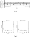
- the original waveform is shown on the left of Figure 6 and the approximation is shown on the right of Figure 6 . It can be seen from Figure 6 that the wavelet approximation follows the shape of the original trace whilst removing some of the resolution in current (mA) readings.
- Figure 7 shows two examples of wavelets with a different number of maximum subdivisions. Two primary effects can be seen as the number of sub-divisions used decreases. Firstly, the variation of the approximation from the original waveform increases, representing the removal of information when forming the wavelet. The second is that any high frequency changes (as can be seen at -180 and -270 in the example) are not well represented by the wavelet approximation. Sudden changes such as these do not represent significant characteristics for the majority of the fault symptoms that would have been selected for classification. However, this is not true in the case of certain fault types, for instance "motor brush wear" fault symptom as this has high frequency oscillations as a principal property for its identification.
- the construction module 123 uses the features to construct a plurality of feature sets each representing a fault type and then trains a supervised machine learning algorithm to classify the fault type associated with the trace.
- the supervised machine learning algorithm may be a Random Forrest.
- the feature sets are constructed by comparing the features from the plurality of traces 117 and identifying distinguishing features from among the features of the traces. The distinguishing features may be identified by comparing features between traces 117 and disregarding substantially identical features.
- the construction module 123 looks at all values that are generated by the Random Forrest for a particular feature. The construction module 123 then generates logic rules to classify. The logic rules classify a fault according to how the feature of a real-time trace compares to the number from the logic rule.
- the feature sets for each fault type, or operating behaviour of the railway point switch 101 are then used to form the trees of the Random Forrest.
- the diagnostic system 113 may include an input 125, a feature extraction module 127, and a classification module 129.
- the input 125 receives the traces 111a, 111b.
- the feature extraction module 127 uses the same pre-processing as described above for the training module 115, and so duplicated description will be omitted.
- those features are classified using the logic rule from the training phase. For instance, if the logic rule has a value of 10.16, the feature of the incoming trace 111a, 111b may be classified as a fault of class 1, 4, or 5, out of 6 potential feature classes, if the feature value from the trace 111a, 111b is higher than 10.16.
- the feature of the incoming trace 111a, 111b may be classified as a fault of class 2, 3, or 6, out of 6 potential feature classes, if the feature value from the trace 111a, 111b, is lower than 10.16.
- Each tree in the Random Forrest provides a decision about which operating behaviour it believes is occurring. For example, the first tree may explain that it is operating normally, and would provide no other information regarding the probabilities of other faults. The decision of all the individual trees is then counted up, and thus the overall probability is obtained.
- the overall probabilities given from the classifier would be 30% Normal, 30% fault A, and 40% fault B.
- a signal is generated that can be sent to an operator terminal (not shown) for retrieval by an operator to investigate.
- the signal may include a message detailing metadata associated with the fault, such as time and date of the event, and a classification label including a description of the classification that is suspected. Probabilities of each of the classes alongside the overall classification label may also be provided.
- a plurality of traces 117 is received at step 200.
- the traces 117 may be pre-processed at step 202.
- Pre-processing firstly normalises the traces 117. Forrest.
- the extracted features are classified using the Random Forrest which applies a value of a feature to the logic rules created during the training phase to generate a likelihood that the trace 111a, 111b is associated with an operating behaviour represented by each feature set.
- the classification of the operating behaviour is estimated based on the probabilities.
- a signal is generated at step 308 indicating the operating behaviour of the railway point switch.
- the signal may be sent to an operator terminal to describe operating behaviour to an operator to aid fault diagnosis.
- a greater proportion of true positive alarms may be provided so that operators' time can be more efficiently used.
- Drawbacks associated with conventional systems include a high proportion of false alarms which produce a burden on the operators as they have to spend time investigating alarms that are not indicative of actual faults.
Description
- The present invention relates to a diagnostic system for diagnosing faults in a railway point switch, a training module for a diagnosing system for diagnosing faults in a railway point switch, a method for diagnosing faults in a railway point switch, and a method for constructing a plurality of feature sets for classifying operating behaviour of a railway point switch.
- The operating behaviour being diagnosed may relate to normal operation or one or more fault types.
- Railway point switches operate by swinging between different lines depending on the direction in which a train is headed. Condition monitoring may be employed to monitor operating behaviour of the point switch, in-use. Conventional condition monitoring typically monitors the behaviour of an electric motor when operating the point switch. For example, average current drawn from an electric motor may be monitored and, when the average current during a swing increases beyond a threshold value, an alarm or warning is sent to a maintenance terminal to advise that the point switch requires investigation to determine if there is a fault.
- Such monitoring means are not reliable at detecting all fault types, for instance faults exhibiting oscillations about a set value, which fault types would not necessarily fall below a threshold value. Also, such means of fault detection require an operator ultimately to assess the waveform in order to diagnose the fault, and so require manual investigation depending on the knowledge and experience of the operator.
-
Document CN 105 787 511 A discloses switch breakdown diagnostic method based on support vector machine. - Accordingly, there is a need to provide improved condition monitoring.
- The present invention is defined by the features of the independent claims.
- It is provided a diagnostic system for diagnosing faults in a railway point switch as defined by the features of
claim 1. The diagnostic system comprises: an input arranged to receive a waveform associated with operating the railway point switch during an event; a feature extraction module arranged to extract characteristic features representing a shape of the waveform; and a classification module arranged to apply the extracted characteristic features to logic rules for classifying the features according to an operating behaviour of the railway point switch during the event, classify the operating behaviour of the railway point switch based on the application of the extracted features to the logic rules, and generate a signal indicating the classified operating behaviour. - By extracting characteristic features representing a shape of the waveform, more detail is provided than merely obtaining an average current value. In this way, the shape of the waveform enables classification of the operating behaviour, for example, normal operation or a fault type, to be diagnosed when classifying the waveform. Accordingly, an automatic classification system is provided which obviates the need for manual investigation of the behaviour of a point switch by a trained operator.
- The characteristic features may be extracted using wavelet approximation. The wavelet approximation is beneficial compared to other reduction techniques since it retains the time resolution of the waveform so that the shape of the wave is maintained. The classification module includes a supervised machine learning algorithm for generating the logic rules for classifying the operating behaviour of the railway point switch.
- The supervised machine learning algorithm comprises a Random Forrest. Use of the Random Forrest reduces overfitting of the data and improves classification accuracy compared to other methods.
- Classifying the operating behaviour of the railway point switch may include selecting subsets of features from the extracted features, generating probabilities that the subsets of the extracted features correspond to each of the feature sets, and identifying a most likely operating behaviour based on the generated probabilities.
- The event may be a swing of the point switch.
- The waveform may represent current drawn during the event versus a time duration of the event. Monitoring current is beneficial since it requires unobtrusive sensors to measure the current, which sensors do not interfere with operating the point switch. The extracted characteristic features may include average current for each period. The waveform may be received in real-time.
- It is provided a training module for a diagnostic system, the diagnostic system for diagnosing faults in a railway point switch as defined by the features of
claim 6. The training module comprises: an input arranged to receive a plurality of waveforms, each waveform associated with an operating behaviour of the railway point switch during an event; a feature extraction module arranged to extract characteristic features representing a shape of the waveforms; and a construction module arranged to construct a plurality of feature sets based on the characteristic features extracted from the waveforms, each feature set corresponding to an operating behaviour of the railway point switch. - The features may be extracted using periodic time series data extraction.
- The feature sets form part of a supervised machine learning algorithm.
- The supervised machine learning algorithm comprises a Random Forrest.
- The features sets may form trees of the Random Forrest.
- The construction module may construct the feature sets by comparing extracted characteristic features between the plurality of waveforms, and disregard substantially identical features.
- The waveform may represent historical, in-service operating behaviour of the railway point switch. It is beneficial to utilise historical in-service waveforms since they will more accurately represent the in-service fault detection waveforms than other waveform types, for example waveforms constructed by industry experts or by simulators. The waveforms provided by in-service may also have a higher degree of representative variation due to other factors such as environmental changes. The degree to which environment effects the equipment is difficult to measure through simulation.
- The feature extraction module may be arranged to normalise the waveforms prior to extracting the features. In this way, seasonal variations affecting the waveforms may be negated.
- The foregoing diagnostic system may include the foregoing training module.
- It is provided a method of diagnosing faults in a railway point switch as defined by the features of claim 11. The method comprises: receiving a waveform associated with operating the railway point switch during an event; extracting characteristic features from the waveform, the characteristic features representing a shape of the waveform; applying the extracted characteristic features to logic rules for classifying the features according to an operating behaviour of the railway point switch during the event; classifying the operating behaviour of the railway point switch based on the application of the extracted characteristic features to the logic rules; and generating a signal indicating the classified operating behaviour.
- It is provided a method of constructing a plurality of feature sets for classifying operating behaviour of a railway point switch as defined by the features of
claim 12. The method comprises: receiving a plurality of waveforms, each waveform associated with an operating behaviour of the railway point switch; extracting characteristic features from the waveforms, the characteristic features representing a shape of the waveform; and constructing a plurality of feature sets based on the characteristic features extracted from the waveforms, each feature set corresponding to an operating behaviour of the railway point switch; and generating logic rules for each feature set for classifying a real-time waveform. - Aspects and embodiments of the disclosed subject-matter are best described with reference to the accompanying figures, of which:
-
Figure 1 shows a railway point switch; -
Figures 2a and 2b show traces associated with operation of the railway point switch fromFigure 1 ; -
Figure 3 shows a block diagram of a diagnostic system according to an embodiment; -
Figure 4 shows a schematic representing a wavelet reduction method for extracting features from waveforms using the diagnostic system fromFigure 3 ; -
Figure 5 shows a schematic representation of subdivisions of a waveform obtained by the wavelet reduction method fromFigure 4 ; -
Figure 6 shows a graph of a waveform and an corresponding waveform approximation obtained using the wavelet reduction method; -
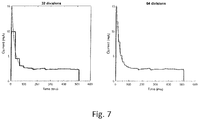
Figure 7 shows a similar view toFigure 6 of two further waveform approximations obtained using the wavelet reduction method; -
Figure 8 shows a flow chart of operating a training module shown inFigure 3 ; and -
Figure 9 shows a flow chart of operating the diagnostic system fromFigure 3 . -
Figure 1 shows a schematic of arailway switch 101 used to guide a train from afirst track 103 to asecond track 105 and aprocessor 109 for executing operating instructions to operate therailway switch 101, in accordance with some embodiments of the present disclosure. - The
railway switch 101 is one example of an electromechanical system in the railway infrastructure and is driven by anelectric motor 107. When activated, therailway switch 101 moves switch blades (not shown) between thefirst track 103 and thesecond track 105 slightly, such that a train approaching the intersection between thefirst track 103 and thesecond track 105 is diverted onto thesecond track 105. - The
railway switch 101 comprises theelectric motor 107 and a gear-mechanism (not shown). Theelectric motor 107 transforms electrical energy into mechanical energy and generates a rotational motion that is used to move the switch blades between thefirst track 103 and thesecond track 105. The gear mechanism may reduce the angular velocity of the motor and amplify the torque applied by the motor to the switch blades. In addition, it may transform the rotational motion into a translational motion. The switch blade mechanism includes springs and dampers configured to control the motion of the switch blades between thefirst track 103 and thesecond track 105. Furthermore, a lock pin or the like may be used to connect theelectric motor 107 via a drive rod with the switch blades. - In embodiments of the present disclosure, measurements of the electrical usage of the
electric motor 107 are made each time therailway switch 101 is operated to switch the points, i.e., move the switch blades. The measurement may be carried out by measuring one of several electrical usage parameters; these parameters may include, for example, the current being drawn by the motor, the voltage drop across the machine, or the power transferred by the machine. Measurements may be made using a suitable meter (current meter, voltmeter, power meter etc.) In the example shown, the measurement is carried out by measuring current drawn by the electric motor during the operation. In some embodiments, the measurement(s) is output in the form of a signal trace or the like to anoperating processor 109. The operatingprocessor 109 may be located proximal to therailway switch 101 or be in a remote location. The processor may use periodic time series extraction to generateindividual traces Figure 2 ) from the measured electrical parameter. - With reference to
Figures 2a and 2b , the signal trace may comprise atrace electric motor 107 with time during operation of therailway switch 101. The electrical parameter used in thetraces Figures 2a and 2b , is the electrical current drawn when operating thepoint switch 101 during an event, for instance a swing event. In particular, the twotraces 111, 111b are traces relating to two different fault types when therailway point switch 101 is operating erroneously. - In the
first trace 111a, relating to the first fault type, the drawn current is seen to overshoot and then quickly decay and oscillate unevenly about a set-point value. The peak in current may be described as a load impulse. In thesecond trace 111b, relating to the second fault type, the load impulse quickly decays and the current oscillates unevenly about a first set-point value, before rising again to oscillate unevenly about a second set-point value. Bothtraces - With reference to
Figure 3 , the processor 109 (seeFigure 1 ) is used to diagnose the fault types associated with each waveform in the first andsecond traces diagnostic system 113 is stored on a memory (not shown) and is executed by theprocessor 109. Thediagnostic system 113 includes atraining module 115 stored as electronic data in the memory. Thetraining module 115 includes aninput 119, afeature extraction module 121, and aconstruction module 123. Theprocessor 109 may be located at trackside or remotely. In the event of the remotely locatedprocessor 109, data is sent wirelessly, for instance by Global Systems for Mobile communications (GSM), at which point the waveform may be applied to the classifier. - The
input 119 received a plurality oftraces 117 representing historical in-service waveforms similar to those shown inFigures 2a and 2b . Alternatively, simulated or manually constructed waveforms may be used, but historical in-service waveforms are preferred since they represent the point switch in a non-ideal environment and are more comparable to the in-service waveforms such as those shown inFigures 2a and 2b . - The
traces 117 may be obtained by performing periodic time series data extraction on a stream of data from the railway switch 101 (Figure 1 ). - The
feature extraction module 121 first normalises thewaveforms 117 to remove any seasonal variations due to weather changes, for example. Next, thefeature extraction module 121 performs pre-processing on thewaveforms 117 to prepare the waveforms for classification. - With reference to
Figure 4 , a trace may be pre-processed by wavelet approximation. Wavelet approximation, unlike many other possible transforms, is advantageous as it retains its time resolution and so the shape of the wave is maintained. Once reduced, the resulting waveform may be considered as an approximation of the original waveform. The approximation includes a plurality of time divisions, each including a mean value (as described below). The mean values in the time divisions may be used to obtain the characteristic features. - The wavelet approximation reduces the wave to a number of residual mean values using the following formula:

- In formula (1), M is the mean value, n is the number of values in a section, and X is the numerical value.
- With reference to
Figure 4 , the full wave may be taken as a first "section", shown at afirst level 140 of division. Formula (1) above is used to determine a mean for this first "section". - The wave is then divided into a number of sections at a lower level, in this case the
second level 142. The maximum number of subdivisions is equal to 2n in order for the wave to be represented uniformly, and this will produce (2n+1-1) wavelet components. - According to
Figure 4 , thesecond level 142 has two "sections" into which the wave is divided. The divisions may be equal in time duration, such that the wave is divided into a first half and a second half each having equal time duration of half of the total time of the wave. -
Figure 4 shows three levels resulting in four sections into which the wave has been divided. The fourth section in thethird level 144 shows formula (2), which is:
- As can be seen from formula (2), a value in a lower level section is taken and the mean value, M, of a higher level section is subtracted from it. In this way, the mean value for the lower level section is determined using all values in that section. For instance, M1 is the mean of the entire wave, M1/2 and M2/2 are then the mean values of the first and second halves of the wave after the mean has been subtracted, and so on. This process can be repeated until either there are a certain maximum number of subdivisions or until there are a maximum number of wavelet components.
- With reference to
Figure 5 , the maximum number of subdivisions is eight, and the maximum number of wavelet components is fifteen. - With reference to
Figure 6 , an original trace can be approximated using the wavelet described above using a maximum number of subdivisions of 16 wavelets. The original waveform is shown on the left ofFigure 6 and the approximation is shown on the right ofFigure 6 . It can be seen fromFigure 6 that the wavelet approximation follows the shape of the original trace whilst removing some of the resolution in current (mA) readings. -
Figure 7 shows two examples of wavelets with a different number of maximum subdivisions. Two primary effects can be seen as the number of sub-divisions used decreases. Firstly, the variation of the approximation from the original waveform increases, representing the removal of information when forming the wavelet. The second is that any high frequency changes (as can be seen at -180 and -270 in the example) are not well represented by the wavelet approximation. Sudden changes such as these do not represent significant characteristics for the majority of the fault symptoms that would have been selected for classification. However, this is not true in the case of certain fault types, for instance "motor brush wear" fault symptom as this has high frequency oscillations as a principal property for its identification. - The
construction module 123 uses the features to construct a plurality of feature sets each representing a fault type and then trains a supervised machine learning algorithm to classify the fault type associated with the trace. The supervised machine learning algorithm may be a Random Forrest. The feature sets are constructed by comparing the features from the plurality oftraces 117 and identifying distinguishing features from among the features of the traces. The distinguishing features may be identified by comparing features betweentraces 117 and disregarding substantially identical features. - During training, the
construction module 123 looks at all values that are generated by the Random Forrest for a particular feature. Theconstruction module 123 then generates logic rules to classify. The logic rules classify a fault according to how the feature of a real-time trace compares to the number from the logic rule. - The feature sets for each fault type, or operating behaviour of the
railway point switch 101, are then used to form the trees of the Random Forrest. - Still with reference to
Figure 3 , thediagnostic system 113 may include aninput 125, afeature extraction module 127, and aclassification module 129. - The
input 125 receives thetraces feature extraction module 127 uses the same pre-processing as described above for thetraining module 115, and so duplicated description will be omitted. Once features have been extracted from a real-time trace incoming trace class trace incoming trace class trace - Each tree in the Random Forrest provides a decision about which operating behaviour it believes is occurring. For example, the first tree may explain that it is operating normally, and would provide no other information regarding the probabilities of other faults. The decision of all the individual trees is then counted up, and thus the overall probability is obtained.
- By way of an illustrative example, if there are ten trees, and three of those ten trees predicted that the point switch was operating normally, three predicted fault A, and 4 predicted fault B. In this case, the overall probabilities given from the classifier would be 30% Normal, 30% fault A, and 40% fault B.
- It should be noted that the operating behaviours relating to the feature sets are not necessarily representative of fault types, since they could also represent the
point switch 101 operating normally. - Once the
trace - With reference to
Figure 8 , operation of the training module may be described in terms of a method. Firstly, a plurality oftraces 117 is received atstep 200. Thetraces 117 may be pre-processed atstep 202. Pre-processing firstly normalises thetraces 117. Forrest. In one embodiment, the extracted features are classified using the Random Forrest which applies a value of a feature to the logic rules created during the training phase to generate a likelihood that thetrace trace step 308 indicating the operating behaviour of the railway point switch. The signal may be sent to an operator terminal to describe operating behaviour to an operator to aid fault diagnosis. In this way, there is reduced burden on the operator since a fault may be diagnosed more accurately and quickly and without input from an expert, as would usually be the case. In addition, a greater proportion of true positive alarms may be provided so that operators' time can be more efficiently used. Drawbacks associated with conventional systems include a high proportion of false alarms which produce a burden on the operators as they have to spend time investigating alarms that are not indicative of actual faults.
Claims (12)
- A diagnostic system (113) for diagnosing faults in a railway point switch (101), the diagnostic system (113) comprising:an input arranged to receive a waveform (117) associated with operating the railway point switch (101) during an event;a feature extraction module (121) arranged to extract characteristic features representing a shape of the waveform (117); anda classification module (129) arranged to apply the extracted characteristic features to logic rules for classifying the features according to an operating behaviour of the railway point switch (101) during the event, classify the operating behaviour of the railway point switch (101) based on the application of the extracted characteristic features to the logic rules, and generate a signal indicating the classified operating behaviour, characterized in that the classification module (129) includes a supervised machine learning algorithm for generating the logic rules for classifying the operating behaviour of the railway point switch (101), wherein the supervised machine learning algorithm comprises a Random Forrest.
- The diagnostic system (113) of Claim 1, wherein the characteristic features are extracted using wavelet approximation.
- The diagnostic system (113) of Claim 1, wherein classifying the operating behaviour of the railway point switch (101) includes selecting subsets of features from the extracted features, generating probabilities that the subsets of the extracted features correspond to each of the feature sets, and identifying a most likely operating behaviour based on the generated probabilities, and optionally wherein the event is a swing of the point switch (101).
- The diagnostic system (113) of any preceding claim, wherein the waveform (117) represents current drawn during the event versus a time duration of the event, and/or wherein the waveform (117) is received in real-time.
- The diagnostic system (113) of Claim 4 wherein the extracted characteristic features include average current for each period.
- A training module (115) for a diagnostic system (113), the diagnostic system (113) for diagnosing faults in a railway point switch (101), the training module (115) comprising:an input (125) arranged to receive a plurality of waveforms (117), each waveform (117) associated with an operating behaviour of the railway point switch (101) during an event;a feature extraction module (121) arranged to extract characteristic features representing a shape of the waveforms (117); anda construction module (123) arranged to construct a plurality of feature sets based on the characteristic features extracted from the waveforms (117), each feature set corresponding to an operating behaviour of the railway point switch (101), characterized in that the feature sets form part of a supervised machine learning algorithm, wherein the supervised machine learning algorithm comprises a Random Forrest.
- The training module (115) of Claim 6, wherein the features are extracted using wavelet approximation.
- The training module (115) of Claim 6, wherein the features sets form trees of the Random Forrest, and optionally wherein the construction module (123) constructs the feature sets by comparing extracted characteristic features between the plurality of waveforms (117), and disregarding substantially identical features.
- The training module (115) of any one of Claims 6 to 8, wherein the waveform (117) represents historical, in-service operating behaviour of the railway point switch (101), wherein the feature extraction module (121) is arranged to normalise the waveforms (117) prior to extracting the features.
- The diagnostic system (113) of any of Claims 1 to 5 comprising the training module (115) of any of Claims 6 to 9.
- A method of diagnosing faults in a railway point switch (101), the method comprising:receiving a waveform associated with operating the railway point switch (101) during an event;extracting characteristic features from the waveform (117), the characteristic features representing a shape of the waveform (117);applying the extracted characteristic features to logic rules for classifying the features according to an operating behaviour of the railway point switch (101) during the event;classifying the operating behaviour of the railway point switch (101) based on the application of the extracted characteristic features to the logic rules; andgenerating a signal indicating the classified operating behaviour of the railway point switch (101), characterized in that the method further comprises generating the logic rules using a supervised machine learning algorithm for classifying the operating behaviour of the railway point switch (101), wherein the supervised machine learning algorithm comprises a Random Forrest.
- A method of constructing a plurality of feature sets for classifying operating behaviour of a railway point switch (101), the method comprising:receiving a plurality of waveforms (117), each waveform (117) associated with an operating behaviour of the railway point switch (101);extracting characteristic features from the waveforms (117), the characteristic features representing a shape of the waveform (117); andconstructing a plurality of feature sets based on the characteristic features extracted from the waveforms (117), each feature set corresponding to an operating behaviour of the railway point switch (101), andgenerating logic rules for each feature set for classifying a real-time waveform,characterized in that the feature sets form part of a supervised machine learning algorithm, wherein the supervised machine learning algorithm comprises a Random Forrest.
Priority Applications (1)
| Application Number | Priority Date | Filing Date | Title |
|---|---|---|---|
| PL20157277T PL3702238T3 (en) | 2019-02-15 | 2020-02-13 | Diagnostic system and a method of diagnosing faults |
Applications Claiming Priority (1)
| Application Number | Priority Date | Filing Date | Title |
|---|---|---|---|
| GB1902157.5A GB2581390B (en) | 2019-02-15 | 2019-02-15 | Diagnostic system and a method of diagnosing faults |
Publications (2)
| Publication Number | Publication Date |
|---|---|
| EP3702238A1 EP3702238A1 (en) | 2020-09-02 |
| EP3702238B1 true EP3702238B1 (en) | 2021-10-13 |
Family
ID=65998474
Family Applications (1)
| Application Number | Title | Priority Date | Filing Date |
|---|---|---|---|
| EP20157277.3A Active EP3702238B1 (en) | 2019-02-15 | 2020-02-13 | Diagnostic system and a method of diagnosing faults |
Country Status (7)
| Country | Link |
|---|---|
| EP (1) | EP3702238B1 (en) |
| DK (1) | DK3702238T3 (en) |
| ES (1) | ES2901684T3 (en) |
| GB (1) | GB2581390B (en) |
| HU (1) | HUE057815T2 (en) |
| PL (1) | PL3702238T3 (en) |
| PT (1) | PT3702238T (en) |
Families Citing this family (6)
| Publication number | Priority date | Publication date | Assignee | Title |
|---|---|---|---|---|
| CN111914320B (en) * | 2020-06-06 | 2024-02-02 | 同济大学 | Sample-free turnout fault diagnosis method based on deep learning |
| CN112319554B (en) * | 2020-10-30 | 2022-12-16 | 交控科技股份有限公司 | Multipoint traction turnout synchronous fault monitoring method and device and electronic equipment |
| CN112224241B (en) * | 2020-11-18 | 2022-08-02 | 中国铁道科学研究院集团有限公司 | Speed acquisition system, fault alarm method and device |
| CN112906230A (en) * | 2021-03-05 | 2021-06-04 | 北京全路通信信号研究设计院集团有限公司 | Turnout fault diagnosis method and device, electronic equipment and medium |
| CN114379619B (en) * | 2021-12-09 | 2023-05-26 | 北京交通大学 | Electrohydraulic switch machine and fault diagnosis system thereof |
| CN115019585B (en) * | 2022-06-27 | 2023-05-26 | 无锡学院 | Teaching and checking system for fault diagnosis of switch machine and control method thereof |
Family Cites Families (8)
| Publication number | Priority date | Publication date | Assignee | Title |
|---|---|---|---|---|
| GB201004421D0 (en) * | 2010-03-17 | 2010-05-05 | Westinghouse Brake & Signal | Condition monitoring |
| GB201016295D0 (en) * | 2010-09-28 | 2010-11-10 | Westinghouse Brake & Signal | Condition monitoring of railway equipment |
| US20150158511A1 (en) * | 2013-12-05 | 2015-06-11 | General Electric Company | Points machine monitoring system and method |
| CN105787511A (en) * | 2016-02-26 | 2016-07-20 | 清华大学 | Track switch fault diagnosis method and system based on support vector machine |
| KR101794543B1 (en) * | 2016-04-18 | 2017-11-08 | 주식회사 세화 | Fault Detection and Classification System of Railway Point Machine by Sound Analysis |
| CN106976468A (en) * | 2017-03-09 | 2017-07-25 | 南京理工大学 | A kind of switch breakdown diagnostic method based on DWT and C SVM |
| CN107054410B (en) * | 2017-04-01 | 2019-06-11 | 广州地铁集团有限公司 | The intelligent diagnosis system and diagnostic method of point machine |
| JP6824121B2 (en) * | 2017-07-14 | 2021-02-03 | 株式会社東芝 | State detection device, state detection method and program |
-
2019
- 2019-02-15 GB GB1902157.5A patent/GB2581390B/en active Active
-
2020
- 2020-02-13 EP EP20157277.3A patent/EP3702238B1/en active Active
- 2020-02-13 HU HUE20157277A patent/HUE057815T2/en unknown
- 2020-02-13 DK DK20157277.3T patent/DK3702238T3/en active
- 2020-02-13 ES ES20157277T patent/ES2901684T3/en active Active
- 2020-02-13 PL PL20157277T patent/PL3702238T3/en unknown
- 2020-02-13 PT PT201572773T patent/PT3702238T/en unknown
Also Published As
| Publication number | Publication date |
|---|---|
| PT3702238T (en) | 2021-12-20 |
| EP3702238A1 (en) | 2020-09-02 |
| GB201902157D0 (en) | 2019-04-03 |
| DK3702238T3 (en) | 2022-01-10 |
| GB2581390A (en) | 2020-08-19 |
| PL3702238T3 (en) | 2022-02-07 |
| GB2581390B (en) | 2021-03-03 |
| ES2901684T3 (en) | 2022-03-23 |
| HUE057815T2 (en) | 2022-06-28 |
Similar Documents
| Publication | Publication Date | Title |
|---|---|---|
| EP3702238B1 (en) | Diagnostic system and a method of diagnosing faults | |
| JP6740247B2 (en) | Anomaly detection system, anomaly detection method, anomaly detection program and learned model generation method | |
| CN108984893B (en) | Gradient lifting method-based trend prediction method | |
| Boškoski et al. | Bearing fault prognostics using Rényi entropy based features and Gaussian process models | |
| Jardine et al. | A review on machinery diagnostics and prognostics implementing condition-based maintenance | |
| EP1360557B1 (en) | Adaptive modelling of changed states in predictive condition monitoring | |
| Martin-del-Campo et al. | Online feature learning for condition monitoring of rotating machinery | |
| US10729382B2 (en) | Methods and systems to predict a state of the machine using time series data of the machine | |
| CN1862278A (en) | Method and system for predicting remaining life for motors featuring on-line insulation condition monitor | |
| CN112036505A (en) | Method and device for determining equipment state of turnout switch machine and electronic equipment | |
| EP2402731A1 (en) | Method for training a system for classifying a roller bearing state, method for classifying a roller bearing state and system for classifying a roller bearing state | |
| CN111538311B (en) | Flexible multi-state self-adaptive early warning method and device for mechanical equipment based on data mining | |
| JP2023524825A (en) | Fault detection of cyber-physical systems | |
| CN112905371B (en) | Software change checking method and device based on heterogeneous multi-source data anomaly detection | |
| CN110060368A (en) | Mechanical method for detecting abnormality based on potential feature coding | |
| Jiang et al. | Automated distribution network fault cause identification with advanced similarity metrics | |
| CN113574480A (en) | Apparatus for predicting equipment damage | |
| CN114563150A (en) | Bridge health online detection module generation method, detection method, tool box and device | |
| GB2584806A (en) | Diagnostic system and a method of diagnosing faults | |
| CN109255201A (en) | A kind of ball screw assembly, health evaluating method based on SOM-MQE | |
| Lahrache et al. | Anomaly detection in a cutting tool by k-means clustering and support vector machines | |
| Brown et al. | Learning models of plant behavior for anomaly detection and condition monitoring | |
| Asada et al. | Development of an effective condition monitoring system for AC point machines | |
| CN109580218B (en) | Blower gear box state identification method based on likelihood learning machine | |
| Kang et al. | Continuous hidden Markov model based gear fault diagnosis and incipient fault detection |
Legal Events
| Date | Code | Title | Description |
|---|---|---|---|
| PUAI | Public reference made under article 153(3) epc to a published international application that has entered the european phase |
Free format text: ORIGINAL CODE: 0009012 |
|
| STAA | Information on the status of an ep patent application or granted ep patent |
Free format text: STATUS: REQUEST FOR EXAMINATION WAS MADE |
|
| 17P | Request for examination filed |
Effective date: 20200213 |
|
| AK | Designated contracting states |
Kind code of ref document: A1 Designated state(s): AL AT BE BG CH CY CZ DE DK EE ES FI FR GB GR HR HU IE IS IT LI LT LU LV MC MK MT NL NO PL PT RO RS SE SI SK SM TR |
|
| AX | Request for extension of the european patent |
Extension state: BA ME |
|
| REG | Reference to a national code |
Ref country code: DE Ref legal event code: R079 Ref document number: 602020000703 Country of ref document: DE Free format text: PREVIOUS MAIN CLASS: B61L0005020000 Ipc: G06N0005000000 |
|
| GRAP | Despatch of communication of intention to grant a patent |
Free format text: ORIGINAL CODE: EPIDOSNIGR1 |
|
| STAA | Information on the status of an ep patent application or granted ep patent |
Free format text: STATUS: GRANT OF PATENT IS INTENDED |
|
| RIC1 | Information provided on ipc code assigned before grant |
Ipc: G06F 17/14 20060101ALI20210315BHEP Ipc: B61L 5/02 20060101ALI20210315BHEP Ipc: B61L 27/00 20060101ALI20210315BHEP Ipc: G06N 20/20 20190101ALI20210315BHEP Ipc: G06N 7/00 20060101ALI20210315BHEP Ipc: G06N 5/00 20060101AFI20210315BHEP |
|
| INTG | Intention to grant announced |
Effective date: 20210413 |
|
| GRAS | Grant fee paid |
Free format text: ORIGINAL CODE: EPIDOSNIGR3 |
|
| GRAA | (expected) grant |
Free format text: ORIGINAL CODE: 0009210 |
|
| STAA | Information on the status of an ep patent application or granted ep patent |
Free format text: STATUS: THE PATENT HAS BEEN GRANTED |
|
| AK | Designated contracting states |
Kind code of ref document: B1 Designated state(s): AL AT BE BG CH CY CZ DE DK EE ES FI FR GB GR HR HU IE IS IT LI LT LU LV MC MK MT NL NO PL PT RO RS SE SI SK SM TR |
|
| REG | Reference to a national code |
Ref country code: GB Ref legal event code: FG4D |
|
| REG | Reference to a national code |
Ref country code: CH Ref legal event code: EP |
|
| REG | Reference to a national code |
Ref country code: DE Ref legal event code: R096 Ref document number: 602020000703 Country of ref document: DE |
|
| REG | Reference to a national code |
Ref country code: IE Ref legal event code: FG4D |
|
| REG | Reference to a national code |
Ref country code: AT Ref legal event code: REF Ref document number: 1438727 Country of ref document: AT Kind code of ref document: T Effective date: 20211115 |
|
| REG | Reference to a national code |
Ref country code: PT Ref legal event code: SC4A Ref document number: 3702238 Country of ref document: PT Date of ref document: 20211220 Kind code of ref document: T Free format text: AVAILABILITY OF NATIONAL TRANSLATION Effective date: 20211214 |
|
| REG | Reference to a national code |
Ref country code: FI Ref legal event code: FGE |
|
| REG | Reference to a national code |
Ref country code: DK Ref legal event code: T3 Effective date: 20220105 |
|
| REG | Reference to a national code |
Ref country code: SE Ref legal event code: TRGR |
|
| REG | Reference to a national code |
Ref country code: NL Ref legal event code: FP |
|
| REG | Reference to a national code |
Ref country code: LT Ref legal event code: MG9D |
|
| REG | Reference to a national code |
Ref country code: NO Ref legal event code: T2 Effective date: 20211013 |
|
| REG | Reference to a national code |
Ref country code: ES Ref legal event code: FG2A Ref document number: 2901684 Country of ref document: ES Kind code of ref document: T3 Effective date: 20220323 |
|
| PG25 | Lapsed in a contracting state [announced via postgrant information from national office to epo] |
Ref country code: RS Free format text: LAPSE BECAUSE OF FAILURE TO SUBMIT A TRANSLATION OF THE DESCRIPTION OR TO PAY THE FEE WITHIN THE PRESCRIBED TIME-LIMIT Effective date: 20211013 Ref country code: LT Free format text: LAPSE BECAUSE OF FAILURE TO SUBMIT A TRANSLATION OF THE DESCRIPTION OR TO PAY THE FEE WITHIN THE PRESCRIBED TIME-LIMIT Effective date: 20211013 Ref country code: BG Free format text: LAPSE BECAUSE OF FAILURE TO SUBMIT A TRANSLATION OF THE DESCRIPTION OR TO PAY THE FEE WITHIN THE PRESCRIBED TIME-LIMIT Effective date: 20220113 |
|
| PG25 | Lapsed in a contracting state [announced via postgrant information from national office to epo] |
Ref country code: IS Free format text: LAPSE BECAUSE OF FAILURE TO SUBMIT A TRANSLATION OF THE DESCRIPTION OR TO PAY THE FEE WITHIN THE PRESCRIBED TIME-LIMIT Effective date: 20220213 Ref country code: LV Free format text: LAPSE BECAUSE OF FAILURE TO SUBMIT A TRANSLATION OF THE DESCRIPTION OR TO PAY THE FEE WITHIN THE PRESCRIBED TIME-LIMIT Effective date: 20211013 Ref country code: HR Free format text: LAPSE BECAUSE OF FAILURE TO SUBMIT A TRANSLATION OF THE DESCRIPTION OR TO PAY THE FEE WITHIN THE PRESCRIBED TIME-LIMIT Effective date: 20211013 Ref country code: GR Free format text: LAPSE BECAUSE OF FAILURE TO SUBMIT A TRANSLATION OF THE DESCRIPTION OR TO PAY THE FEE WITHIN THE PRESCRIBED TIME-LIMIT Effective date: 20220114 |
|
| REG | Reference to a national code |
Ref country code: HU Ref legal event code: AG4A Ref document number: E057815 Country of ref document: HU |
|
| REG | Reference to a national code |
Ref country code: DE Ref legal event code: R097 Ref document number: 602020000703 Country of ref document: DE |
|
| PG25 | Lapsed in a contracting state [announced via postgrant information from national office to epo] |
Ref country code: SM Free format text: LAPSE BECAUSE OF FAILURE TO SUBMIT A TRANSLATION OF THE DESCRIPTION OR TO PAY THE FEE WITHIN THE PRESCRIBED TIME-LIMIT Effective date: 20211013 Ref country code: SK Free format text: LAPSE BECAUSE OF FAILURE TO SUBMIT A TRANSLATION OF THE DESCRIPTION OR TO PAY THE FEE WITHIN THE PRESCRIBED TIME-LIMIT Effective date: 20211013 Ref country code: EE Free format text: LAPSE BECAUSE OF FAILURE TO SUBMIT A TRANSLATION OF THE DESCRIPTION OR TO PAY THE FEE WITHIN THE PRESCRIBED TIME-LIMIT Effective date: 20211013 |
|
| PLBE | No opposition filed within time limit |
Free format text: ORIGINAL CODE: 0009261 |
|
| STAA | Information on the status of an ep patent application or granted ep patent |
Free format text: STATUS: NO OPPOSITION FILED WITHIN TIME LIMIT |
|
| 26N | No opposition filed |
Effective date: 20220714 |
|
| PG25 | Lapsed in a contracting state [announced via postgrant information from national office to epo] |
Ref country code: MC Free format text: LAPSE BECAUSE OF FAILURE TO SUBMIT A TRANSLATION OF THE DESCRIPTION OR TO PAY THE FEE WITHIN THE PRESCRIBED TIME-LIMIT Effective date: 20211013 |
|
| REG | Reference to a national code |
Ref country code: BE Ref legal event code: MM Effective date: 20220228 |
|
| PG25 | Lapsed in a contracting state [announced via postgrant information from national office to epo] |
Ref country code: AL Free format text: LAPSE BECAUSE OF FAILURE TO SUBMIT A TRANSLATION OF THE DESCRIPTION OR TO PAY THE FEE WITHIN THE PRESCRIBED TIME-LIMIT Effective date: 20211013 |
|
| PG25 | Lapsed in a contracting state [announced via postgrant information from national office to epo] |
Ref country code: SI Free format text: LAPSE BECAUSE OF FAILURE TO SUBMIT A TRANSLATION OF THE DESCRIPTION OR TO PAY THE FEE WITHIN THE PRESCRIBED TIME-LIMIT Effective date: 20211013 |
|
| PG25 | Lapsed in a contracting state [announced via postgrant information from national office to epo] |
Ref country code: IE Free format text: LAPSE BECAUSE OF NON-PAYMENT OF DUE FEES Effective date: 20220213 |
|
| PG25 | Lapsed in a contracting state [announced via postgrant information from national office to epo] |
Ref country code: BE Free format text: LAPSE BECAUSE OF NON-PAYMENT OF DUE FEES Effective date: 20220228 |
|
| PGFP | Annual fee paid to national office [announced via postgrant information from national office to epo] |
Ref country code: RO Payment date: 20230110 Year of fee payment: 4 Ref country code: NO Payment date: 20230208 Year of fee payment: 4 Ref country code: LU Payment date: 20230125 Year of fee payment: 4 Ref country code: ES Payment date: 20230314 Year of fee payment: 4 Ref country code: DK Payment date: 20230213 Year of fee payment: 4 Ref country code: CZ Payment date: 20230117 Year of fee payment: 4 Ref country code: CH Payment date: 20230307 Year of fee payment: 4 |
|
| PGFP | Annual fee paid to national office [announced via postgrant information from national office to epo] |
Ref country code: TR Payment date: 20230213 Year of fee payment: 4 Ref country code: PT Payment date: 20230213 Year of fee payment: 4 Ref country code: PL Payment date: 20230102 Year of fee payment: 4 Ref country code: IT Payment date: 20230228 Year of fee payment: 4 Ref country code: HU Payment date: 20221227 Year of fee payment: 4 Ref country code: DE Payment date: 20221220 Year of fee payment: 4 |
|
| P01 | Opt-out of the competence of the unified patent court (upc) registered |
Effective date: 20230518 |
|
| PGFP | Annual fee paid to national office [announced via postgrant information from national office to epo] |
Ref country code: GB Payment date: 20231221 Year of fee payment: 5 |
|
| PGFP | Annual fee paid to national office [announced via postgrant information from national office to epo] |
Ref country code: SE Payment date: 20231228 Year of fee payment: 5 Ref country code: NL Payment date: 20231226 Year of fee payment: 5 Ref country code: FR Payment date: 20231222 Year of fee payment: 5 Ref country code: FI Payment date: 20231226 Year of fee payment: 5 |
|
| PGFP | Annual fee paid to national office [announced via postgrant information from national office to epo] |
Ref country code: LU Payment date: 20240129 Year of fee payment: 5 |
|
| PGFP | Annual fee paid to national office [announced via postgrant information from national office to epo] |
Ref country code: ES Payment date: 20240307 Year of fee payment: 5 |