EP3702218A1 - A container for a vehicle and a heavy vehicle cab provided with the same container - Google Patents
A container for a vehicle and a heavy vehicle cab provided with the same container Download PDFInfo
- Publication number
- EP3702218A1 EP3702218A1 EP20159536.0A EP20159536A EP3702218A1 EP 3702218 A1 EP3702218 A1 EP 3702218A1 EP 20159536 A EP20159536 A EP 20159536A EP 3702218 A1 EP3702218 A1 EP 3702218A1
- Authority
- EP
- European Patent Office
- Prior art keywords
- space
- panel
- frame
- container
- container according
- Prior art date
- Legal status (The legal status is an assumption and is not a legal conclusion. Google has not performed a legal analysis and makes no representation as to the accuracy of the status listed.)
- Granted
Links
Images


Classifications
-
- B—PERFORMING OPERATIONS; TRANSPORTING
- B60—VEHICLES IN GENERAL
- B60R—VEHICLES, VEHICLE FITTINGS, OR VEHICLE PARTS, NOT OTHERWISE PROVIDED FOR
- B60R7/00—Stowing or holding appliances inside vehicle primarily intended for personal property smaller than suit-cases, e.g. travelling articles, or maps
- B60R7/02—Stowing or holding appliances inside vehicle primarily intended for personal property smaller than suit-cases, e.g. travelling articles, or maps in separate luggage compartment
-
- B—PERFORMING OPERATIONS; TRANSPORTING
- B60—VEHICLES IN GENERAL
- B60R—VEHICLES, VEHICLE FITTINGS, OR VEHICLE PARTS, NOT OTHERWISE PROVIDED FOR
- B60R7/00—Stowing or holding appliances inside vehicle primarily intended for personal property smaller than suit-cases, e.g. travelling articles, or maps
- B60R7/04—Stowing or holding appliances inside vehicle primarily intended for personal property smaller than suit-cases, e.g. travelling articles, or maps in driver or passenger space, e.g. using racks
-
- B—PERFORMING OPERATIONS; TRANSPORTING
- B62—LAND VEHICLES FOR TRAVELLING OTHERWISE THAN ON RAILS
- B62D—MOTOR VEHICLES; TRAILERS
- B62D35/00—Vehicle bodies characterised by streamlining
- B62D35/001—For commercial vehicles or tractor-trailer combinations, e.g. caravans
-
- B—PERFORMING OPERATIONS; TRANSPORTING
- B62—LAND VEHICLES FOR TRAVELLING OTHERWISE THAN ON RAILS
- B62D—MOTOR VEHICLES; TRAILERS
- B62D33/00—Superstructures for load-carrying vehicles
- B62D33/06—Drivers' cabs
Definitions
- the invention relates to a container for a vehicle.
- a habitable cab typically contains, on the inside, one or more containers, which are suited to store objects in an orderly and safe fashion.
- collapsible containers are known, namely that can be configured either in an extended condition, in which they can house objects, or in a collapsed condition, in which they free useful space.
- collapsible containers often comprise a plurality of movable parts, which are connected to one another and to the cab, so as to ensure the stiffness of the containers in the extended condition.
- the object of the invention is to fulfil the needs discussed above in a simple and economic fashion.
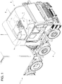
- reference number 1 indicates, as a whole, a vehicle, in particular a heavy vehicle provided with a cab 2 designed to accommodate a user U.
- the cab 2 comprises a known structure 4, which is provided with a plurality of walls, among which there are, for example, a floor 3, a roof 5 and a rear wall 6, which are connected to one another so as define a habitable space 7 for the user U.
- the cab 2 further comprises a driver's seat 8 and a bed 9, which are carried by the structure 4 in a movable manner.
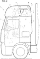
- the bed 9 is coupled to the roof 5 in a vertically movable manner between a lifted position ( figure 2 ), in which it is closer to the roof 5, and a lower position, in which it is farther from the roof 5 and is arranged at approximately half the height relative to the floor 3.
- the cab 2 comprises a container 10 having a frame 11, which is directly or indirectly coupled to the structure 4 and is suitable, in use, to support personal objects of the user U.
- the frame 11 preferably comprises a base panel or shelf 12, a pair of sides 13 and a roof 14, which are connected to one another so as to delimit, in use, a compartment 15, in which the user U can store objects in an orderly fashion.
- the panel 12 is arranged horizontally and, therefore, is designed to support the objects inside the compartment 15.
- the frame 11 comprises at least one inflatable portion, namely a portion which can be configured in a deflated state, in which it occupies a space having a minimum volume, and an inflated state, in which the space taken up is larger.
- the said inflatable portion comprises the panel 12.
- the panel 12 is empty on the inside, namely it is provided with an outer wall 23 ( figure 3 ), which delimits, on the inside, a space 24, which can be filled with a pressurised inflating gas.
- the panel 12 comprises a known sealing valve 20 ( figure 4 ), which is carried by the wall 23 in a fixed position.
- the sealing valve 20 can be connected to a source of the pressurised inflating gas, so as to let a flow thereof through the wall 23 towards the space 24.
- the panel 12 comprises a known release, which is not shown herein.
- the volume of the space 24 is minimum, whereas the volume of the space 24 is maximum when the panel 12 is in the inflated state ( figures 4 and 5 ). Furthermore, when it is in the deflated state, the panel 12 is flexible, can be folded and/or can be rolled.
- the wall 23 has two wall portions 25, 26 ( figures 3 and 6 ), which face one another and define, when the frame 11 is coupled to the structure 4 and the panel 12 is in the inflated state, respective outer horizontal surfaces 27, 28; the wall portions 25, 26 are, for example, multi-layer portions.
- the layer most on the outside is made of a thermosetting or thermoplastic polymer material, in particular polyvinyl chloride (PVC).
- wall portions 25, 26 comprise respective fabric layers 31, 32, which delimit the space 24.
- the fabric layers 31, 32 are made of a polymer base, for example comprising polyesters or aliphatic polyamides, also known as Nylon®.
- the fabric layers 31, 32 are sewn to one another by means of a plurality of thread segments 33, which are arranged inside the space 24 and are made, for example, of a polymer fibre, preferably the same as the one of the fabric layers 31, 32.
- the thread segments 33 extend crosswise to the wall portions 25, 26 when the panel 12 is in the inflated state, as they are stretched by means of the pressure of the inflating gas.
- the fact that the thread segments 33 are stretched prevents the surfaces 27 and 28 from arbitrarily spreading apart during and after the filling of the space 24. More in detail, the surfaces 27, 28 remain fixed relative to one another when the pressure in the space 24 exceeds a threshold that is such that the thread segments 33 are stretched.
- the thread segments 33 are part of a plurality of threads, which are sewn so as to go through both fabric layers 31, 32 many times and in different points. Therefore, the thread segments 33 each have a predetermined length and each extend between a corresponding point of the fabric layer 31 and a corresponding point of the fabric layer 32.
- the distance between the surface 27 and the surface 28 is constant and is determined by the length of the thread segments 33.
- the surfaces 27 and 28 are flat and parallel to one another.
- the pressure of the inflating gas combined with the fact that the thread segments 33 are stretched, ensures a high rigidity of the panel 12 and of the entire frame 11; in particular, the space 24 can be filled with the inflating gas at relatively high pressures, for example up to 1.5 bar.
- the wall portions 25, 26 are the same in terms of dimensions and geometry and they come in contact with one another as soon as the panel 12 changes to the deflated state.
- the surface 27 is suited to receive the objects, which rest against it, and, in particular, has a symmetrical shape relative to a horizontal symmetry axis B.
- the sealing valve 20 is arranged at the surface 28.
- the roof 14 conveniently comprises a panel 36, which has, in particular, a wall 37 delimiting, on the inside, a space 38, which is also inflatable.
- the panel 36 can be configured in an inflated state and in a deflated state.
- the wall 37 preferably is similar to the wall 23, which is why it will not be described in detail for the sake of brevity.
- the frame 11 conveniently comprises at least one duct 44, which establishes a fluid communication between the space 24 and the space 38. More precisely, the frame 11 comprises a plurality of ducts 44, which extend between the panels 12, 36 along a direction C, which is transverse to the surface 27, are fixed to the panels 12, 36 and are expandable as well as collapsible.
- two of the ducts 44 are part of the sides 13, respectively; more in particular, the sides 13 have the same structure as the panels 12 and 36, namely they comprise respective outer wall portions, which are sewn by means of thread segments (which are not shown).
- the panels 12, 36 in the deflated state, can be moved relative to one another so as to come in contact with one another and, in the inflated state, the pressure of the ducts 44 keeps the panels 12, 36 spaced apart from one another along a direction, which is transverse to the surface 27.
- the space 38 receives, through the ducts 44, the pressurised inflating gas, which causes the panel 36 to move away from the panel 12, the ducts 44 to expand and the panel 36 to be inflated.
- the ducts 44 exert a constraining reaction upon the panels 12, 36, which prevents the panels 12, 36 from further moving apart and, hence, help stiffen the frame 11.
- some ducts 44 are defined by tubes arranged according to rows parallel to the axis B between the sides 13 and form, in the inflated state of the panels 12, 36, a plurality of uprights aimed at supporting the panels 12, 36 in an intermediate area of the compartment 15.
- each row is arranged between the axis B and a respective side 13.
- the container 10 comprises a plate 48, which is coupled, in a releasable manner, to the panels 12, 36 in the inflated state so as to at least partially close the compartment 15 at the back, namely on the opposite side relative to a front opening, through which the user U, in use, accesses the compartment 15.
- the material of the plate 48 is the same as the one of the outer layers of the wall portions 25, 26.
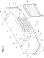
- the container 10 conveniently comprises a grating 49 ( figure 5 ), which is coupled, in a releasable manner, to the panels 12, 36 in the inflated state so as to at least partially close the front opening of the compartment 15.
- the material of the grating 49 is the same as the one of the outer layers of the wall portions 25, 26.
- the grating 49 has a function that counteracts the falling of the objects inside the compartment 15, without preventing the user U to see the same objects.
- the container 10 comprises a coupling device 50, which is fixed relative to the frame 11 and can be coupled, in a fixed position and in a releasable manner, to a coupling interface 52, which is carried by the structure 4.
- the coupling device 50 comprises a plurality of releasable fixing members 51, for example elastic pins (designed to be locked into or forced into respective seats of the interface 52), threaded elements or adhesive strips or Velcro® strips, which are preferably carried by the wall 37.
- the coupling interface 52 is arranged at the bed 9, is carried by the bed 9 in a fixed position and comprises, more in particular, a plurality of fixing seats, which are suitable for being engaged by the fixing members 51.
- the container 10 comprises a half-shell 55, which is coupled to the panel 12 in a fixed position and defines a cavity, which is engaged by the panel 12, at least when the latter is in the deflated state.
- the perimeter of the half-shell 55 has an edge 56, which delimits an opening 57, which is parallel to the surface 27 and defines an access to the aforesaid cavity.
- the half-shell 55 is perforated on the side opposite the opening 57 at the sealing valve 20, so that the latter can be coupled to the source of inflating gas, for example by means of a tube 58 ( figure 2 ).
- the panel 12 and the ducts 44 When the panel 12 and the ducts 44 are deflated, the panel 12 can be lifted.
- the cavity defined by the half-shell 55 also contains the panel 36 and the sides 13, namely the frame 11.
- the edge 56 is carried by the structure 4 in a releasable manner, for example through connection elements which are not shown herein, so that the opening 57 is closed and the half-shell 55 is held in the compact configuration by the structure 4 and/or by the bed 9.
- the edge 56 is fixed to the bed 9, which closes the opening 57, in the compact configuration of the frame 11, so that the latter is hidden to the user U.
- the user U couples the sealing valve 20 to the source of inflating gas through the tube 58. Thanks to the pressure of the inflating gas, the edge 56 moves away from the bed 9, while the space 24 gets filled and the panel 12 shifts to the inflated state.
- the inflating gas expands the ducts 44 and flows, through the ducts 44, into the space 38, which is thus filled by the inflating gas together with the panel 36 and the ducts 44, which shift to the inflated state.
- the user U couples the plate 48 to the panels 12, 36 and the grating 49 after having introduced the objects into the compartment 15.
- number 10' indicates a container according to a further embodiment of the invention.
- the container 10' is similar to the container 10 and will be described below only in those aspects that distinguish the former from the latter; corresponding or equivalent parts of the containers 10, 10' will be indicated, when possible, with the same reference numbers.
- a difference between the container 10' and the container 10 lies in the fact that the former comprises a frame 11' without the sides 13; instead of the sides 13, the container 10' comprises a pair of plates 48', which are coupled to the panels 12, 36 in a releasable manner.
- the material of the plates 48' is the same as the one of the outer layers of the wall portions 25, 26.
- the container 10' comprises a coupling device 50', which comprises, in turn, a support panel 60', which can be coupled to the frame 11' in a fixed position, and coupling members 51', which are carried by the support panel 60' in a fixed position and are similar to the members 51, so as to couple the support panel 60' to the structure 4 in a releasable manner.
- a coupling device 50' which comprises, in turn, a support panel 60', which can be coupled to the frame 11' in a fixed position, and coupling members 51', which are carried by the support panel 60' in a fixed position and are similar to the members 51, so as to couple the support panel 60' to the structure 4 in a releasable manner.
- the panel 60' similarly to the panels 12, 36 is inflatable, so that it defines an inflatable space; in particular, the panel 60' has the same structure as the panels 12 and 36, namely it comprises outer wall portions, which are sewn by means of thread segments (which are not shown).
- the panel 60' comprises a sealing valve 61'.
- the following description will relate to the panel 60' in the inflated state; in the deflated state, the panel 60' can be folded, is flexible and/or can be rolled, like the panels 12, 36.
- the panel 60' closes the compartment 15 at the back, when it is coupled to the frame 11', and comprises a plate 63' and at least one plate 64', which is coupled to the plate 63' in a rotary manner so as to rotate around an axis D', which is vertical in use.
- the panel 60' comprises two rotary plates 64', which can rotate around respective axes D' at the ends of the plate 63', according to a direction that is parallel to the panels 12, 36 in the inflated state.
- the plates 64' can rotate between a rest position, in which they are parallel to the plate 63', and a use position, in which they are orthogonal to the plate 63' and define, together with the plates 48', the sides of the compartment 15.
- the plates 48' carry releasable attachment elements 65', for example a pair of adhesive strips, so as to be carried by the respective plates 64' in a releasable position.
- the attachment elements 65' could be carried by the portions 64' and/or be made of Velcro®.
- the plate 63' carries the attachment members 51' in a fixed position; correspondingly, a coupling interface (which is not shown herein) is carried by the rear wall 6, under the bed 9 when the latter is in the lifted position, so as to allow for the fixing of the coupling device 50'.
- the operation of the container 10' is similar to the one of the container 10 and will be described only in what distinguishes it from the one of the container 10.
- the user U before inflating the panels 12, 36 and the ducts 44, the user U connect the sealing valve 61' to the source of inflating gas, for example through a tube 58'. In this way, the panel 60' shifts to the inflated state; then, after having caused the frame 11 to reach the inflated state as well, the user U couples the plates 64' in the use position to the plates 48', which were previously coupled to the panels 12, 36 in the inflated state.
- the panel 12 is substantially flat, namely is lacks those annoying swellings that typical of known inflatable panels.
- This allows the frames 11, 11' to be easily coupled to the structure 4 and, at the same time, to be significantly rigid; moreover, they tend to steadily maintain their shape in order to support the objects in an effective manner.
- the frames 11, 11' could be, for example, fixed to the floor 3.
- the stiffness of the frame 11, 11' is ensured by the pressure of the inflating gas and no further stiffening elements need to be used.
- the frames 11, 11' occupy an irrelevant space when the panels 12, 36, 60' are in the deflated state, thanks, among other things, to the possibility of folding or rolling the panels 12, 36, 60'.
- the space left free inside the cab 2 can be used for other purposes, for example moving the bed 9 to the lowered position.
- the containers 10, 10' could comprise further panels similar to the panels 12, 36, 60', or the panels 36, 60' could be absent or have constructive features that are different compared to those of the panel 12, in particular they could not be inflatable.
- thread segments 33 could be replaced by other types of flexible ties or mechanisms having the same constraining function and the same shape, so as to connect the wall portions 25, 26 to one another.
- the space 38 could not be in fluid communication with the space 24 and the upper ends of the ducts 44 could be fixed to the panel 36 in a fluid-tight manner, so that the inflating gas introduced into the space 24 causes anyway the expansion of the ducts 44.
- sealing valves 20, 61' could be configured so as to allow for the release of the inflating gas, when appropriate, and/or be available in a different number.
Landscapes
- Engineering & Computer Science (AREA)
- Mechanical Engineering (AREA)
- Chemical & Material Sciences (AREA)
- Combustion & Propulsion (AREA)
- Transportation (AREA)
- Air Bags (AREA)
- Specific Sealing Or Ventilating Devices For Doors And Windows (AREA)
- Vehicle Step Arrangements And Article Storage (AREA)
Abstract
Description
- This patent application claims priority from Italian patent application no.
102019000002771 - The invention relates to a container for a vehicle.
- As it is known, some vehicles, in particular heavy vehicles, are provided with a habitable cab, which typically contains, on the inside, one or more containers, which are suited to store objects in an orderly and safe fashion.
- Even though they are useful to fulfil the aforesaid purpose, these containers occupy spaces that could otherwise be habitable or could be used in a different way to install other elements.
- Therefore, there is the need to store objects, in an orderly fashion, inside containers, which do not decrease the useful spaces available inside the vehicles.
- To this regard, collapsible containers are known, namely that can be configured either in an extended condition, in which they can house objects, or in a collapsed condition, in which they free useful space.
- These collapsible containers often comprise a plurality of movable parts, which are connected to one another and to the cab, so as to ensure the stiffness of the containers in the extended condition.
- In general, alternative solutions are needed, which are simpler compared to known collapsible containers, but are at least as rigid as them in the extended condition, and have substantially flat supporting walls for the objects or, anyway, supporting walls that are such as to ensure the stability of the objects resting against them.
- The object of the invention is to fulfil the needs discussed above in a simple and economic fashion.
- The aforesaid object is reached by a container for a vehicle and by a cab of a heavy vehicle provided with said container according to the appended claims.
- The invention will be best understood upon perusal of the following detailed description of preferred embodiments, which are provided by way of non-limiting example, with reference to the accompanying drawings, wherein:
-
figure 1 shows, in a perspective view and with parts removed for clarity, a heavy vehicle provided with a cab comprising a container according to an embodiment of the invention; -
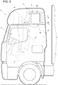
figures 2 and3 are side views, on a larger scale, which show the container offigure 1 in a collapsed condition and in an extended condition, respectively; -
figure 4 is a perspective view, on a larger scale, of the container in the extended condition offigure 3 ; -
figure 5 is a further enlargement of the container shown infigure 4 ; -
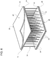
figure 6 shows, in a cross-sectional view, an enlarged detail of the container offigure 4 and5 ; -
Figure 7 shows, in an exploded view, a container according to a further embodiment of the invention; and -
figure 8 shows, in a perspective view, a detail of the container offigure 7 . - In
figure 1 ,reference number 1 indicates, as a whole, a vehicle, in particular a heavy vehicle provided with acab 2 designed to accommodate a user U. - The
cab 2 comprises a knownstructure 4, which is provided with a plurality of walls, among which there are, for example, afloor 3, aroof 5 and arear wall 6, which are connected to one another so as define ahabitable space 7 for the user U. - As visible from
figure 2 , thecab 2 further comprises a driver'sseat 8 and abed 9, which are carried by thestructure 4 in a movable manner. - In particular, the
bed 9 is coupled to theroof 5 in a vertically movable manner between a lifted position (figure 2 ), in which it is closer to theroof 5, and a lower position, in which it is farther from theroof 5 and is arranged at approximately half the height relative to thefloor 3. - Furthermore, the
cab 2 comprises acontainer 10 having aframe 11, which is directly or indirectly coupled to thestructure 4 and is suitable, in use, to support personal objects of the user U. - The
frame 11 preferably comprises a base panel orshelf 12, a pair ofsides 13 and aroof 14, which are connected to one another so as to delimit, in use, acompartment 15, in which the user U can store objects in an orderly fashion. - When the
frame 11 is in use, as it is shown, for example, infigure 1 , thepanel 12 is arranged horizontally and, therefore, is designed to support the objects inside thecompartment 15. - The
frame 11 comprises at least one inflatable portion, namely a portion which can be configured in a deflated state, in which it occupies a space having a minimum volume, and an inflated state, in which the space taken up is larger. - In the embodiments shown herein, the said inflatable portion comprises the
panel 12. In other words, thepanel 12 is empty on the inside, namely it is provided with an outer wall 23 (figure 3 ), which delimits, on the inside, aspace 24, which can be filled with a pressurised inflating gas. - In order to allow the
space 24 to be filled, thepanel 12 comprises a known sealing valve 20 (figure 4 ), which is carried by thewall 23 in a fixed position. - The sealing
valve 20 can be connected to a source of the pressurised inflating gas, so as to let a flow thereof through thewall 23 towards thespace 24. - On the other hand, in order to allow the
space 24 to be emptied, thepanel 12 comprises a known release, which is not shown herein. - When the
panel 12 is in the deflated state, the volume of thespace 24 is minimum, whereas the volume of thespace 24 is maximum when thepanel 12 is in the inflated state (figures 4 and5 ). Furthermore, when it is in the deflated state, thepanel 12 is flexible, can be folded and/or can be rolled. - The
wall 23 has twowall portions 25, 26 (figures 3 and6 ), which face one another and define, when theframe 11 is coupled to thestructure 4 and thepanel 12 is in the inflated state, respective outerhorizontal surfaces wall portions - Furthermore, the
wall portions respective fabric layers space 24. - In particular, the
fabric layers - The
fabric layers thread segments 33, which are arranged inside thespace 24 and are made, for example, of a polymer fibre, preferably the same as the one of thefabric layers - The
thread segments 33 extend crosswise to thewall portions panel 12 is in the inflated state, as they are stretched by means of the pressure of the inflating gas. - In this way, the fact that the
thread segments 33 are stretched prevents thesurfaces space 24. More in detail, thesurfaces space 24 exceeds a threshold that is such that thethread segments 33 are stretched. - The
thread segments 33 are part of a plurality of threads, which are sewn so as to go through bothfabric layers thread segments 33 each have a predetermined length and each extend between a corresponding point of thefabric layer 31 and a corresponding point of thefabric layer 32. - Owing to the above, assuming that the
panel 12 is in the inflated state, the distance between thesurface 27 and thesurface 28 is constant and is determined by the length of thethread segments 33. - In order to sew the
fabric layers - Specifically, thanks to a specific choice of the lengths of the
thread segments 33, thesurfaces - The pressure of the inflating gas, combined with the fact that the
thread segments 33 are stretched, ensures a high rigidity of thepanel 12 and of theentire frame 11; in particular, thespace 24 can be filled with the inflating gas at relatively high pressures, for example up to 1.5 bar. - As visible from
figure 4 , where thepanel 12 is shown in the inflated state, thewall portions panel 12 changes to the deflated state. - The
surface 27 is suited to receive the objects, which rest against it, and, in particular, has a symmetrical shape relative to a horizontal symmetry axis B. In particular, thesealing valve 20 is arranged at thesurface 28. - The
roof 14 conveniently comprises apanel 36, which has, in particular, awall 37 delimiting, on the inside, aspace 38, which is also inflatable. In other words, like thepanel 12, thepanel 36 can be configured in an inflated state and in a deflated state. - The
wall 37 preferably is similar to thewall 23, which is why it will not be described in detail for the sake of brevity. - In order to allow the
space 38 to be filled, theframe 11 conveniently comprises at least oneduct 44, which establishes a fluid communication between thespace 24 and thespace 38. More precisely, theframe 11 comprises a plurality ofducts 44, which extend between thepanels surface 27, are fixed to thepanels - In particular, two of the
ducts 44 are part of thesides 13, respectively; more in particular, thesides 13 have the same structure as thepanels - Thanks to the expandable character of the
ducts 44, in the deflated state, thepanels ducts 44 keeps thepanels surface 27. - Indeed, during the filling of the
space 24, thespace 38 receives, through theducts 44, the pressurised inflating gas, which causes thepanel 36 to move away from thepanel 12, theducts 44 to expand and thepanel 36 to be inflated. - Once the
ducts 44 are extended, theducts 44 exert a constraining reaction upon thepanels panels frame 11. - In the example shown in
figures 1 to 5 , someducts 44 are defined by tubes arranged according to rows parallel to the axis B between thesides 13 and form, in the inflated state of thepanels panels compartment 15. In particular, each row is arranged between the axis B and arespective side 13. - Furthermore, the
container 10 comprises aplate 48, which is coupled, in a releasable manner, to thepanels compartment 15 at the back, namely on the opposite side relative to a front opening, through which the user U, in use, accesses thecompartment 15. - For example, the material of the
plate 48 is the same as the one of the outer layers of thewall portions - Moreover, the
container 10 conveniently comprises a grating 49 (figure 5 ), which is coupled, in a releasable manner, to thepanels compartment 15. For example, the material of the grating 49 is the same as the one of the outer layers of thewall portions compartment 15, without preventing the user U to see the same objects. - With reference to
figure 5 , thecontainer 10 comprises acoupling device 50, which is fixed relative to theframe 11 and can be coupled, in a fixed position and in a releasable manner, to acoupling interface 52, which is carried by thestructure 4. In particular, thecoupling device 50 comprises a plurality of releasable fixingmembers 51, for example elastic pins (designed to be locked into or forced into respective seats of the interface 52), threaded elements or adhesive strips or Velcro® strips, which are preferably carried by thewall 37. - In particular, the
coupling interface 52 is arranged at thebed 9, is carried by thebed 9 in a fixed position and comprises, more in particular, a plurality of fixing seats, which are suitable for being engaged by the fixingmembers 51. - Furthermore, the
container 10 comprises a half-shell 55, which is coupled to thepanel 12 in a fixed position and defines a cavity, which is engaged by thepanel 12, at least when the latter is in the deflated state. - The perimeter of the half-
shell 55 has anedge 56, which delimits anopening 57, which is parallel to thesurface 27 and defines an access to the aforesaid cavity. - Furthermore, the half-
shell 55 is perforated on the side opposite theopening 57 at the sealingvalve 20, so that the latter can be coupled to the source of inflating gas, for example by means of a tube 58 (figure 2 ). - When the
panel 12 and theducts 44 are deflated, thepanel 12 can be lifted. In this compact configuration of theframe 11, the cavity defined by the half-shell 55 also contains thepanel 36 and thesides 13, namely theframe 11. Furthermore, according tofigure 2 , theedge 56 is carried by thestructure 4 in a releasable manner, for example through connection elements which are not shown herein, so that theopening 57 is closed and the half-shell 55 is held in the compact configuration by thestructure 4 and/or by thebed 9. - In particular, with reference to
figure 2 , theedge 56 is fixed to thebed 9, which closes theopening 57, in the compact configuration of theframe 11, so that the latter is hidden to the user U. - The operation of the
container 10 will now be described with reference tofigures 2 and3 , in which theframe 11 is already coupled, in a fixed position, to thebed 9, whereas the latter is in the lifted position. - As visible in
figure 2 , after having released the half-shell 55 from thebed 9, the user U couples the sealingvalve 20 to the source of inflating gas through thetube 58. Thanks to the pressure of the inflating gas, theedge 56 moves away from thebed 9, while thespace 24 gets filled and thepanel 12 shifts to the inflated state. - Ad the same time, the inflating gas expands the
ducts 44 and flows, through theducts 44, into thespace 38, which is thus filled by the inflating gas together with thepanel 36 and theducts 44, which shift to the inflated state. - At this point, the user U disconnects the
tube 58 and, as a consequence, the sealingvalve 20 automatically closes. - Finally, the user U couples the
plate 48 to thepanels compartment 15. - With reference to
figure 7 , number 10' indicates a container according to a further embodiment of the invention. - The container 10' is similar to the
container 10 and will be described below only in those aspects that distinguish the former from the latter; corresponding or equivalent parts of thecontainers 10, 10' will be indicated, when possible, with the same reference numbers. - For example, a difference between the container 10' and the
container 10 lies in the fact that the former comprises a frame 11' without thesides 13; instead of thesides 13, the container 10' comprises a pair of plates 48', which are coupled to thepanels - For example, the material of the plates 48' is the same as the one of the outer layers of the
wall portions - Furthermore, instead of the
plate 48 and thecoupling device 50 of thecontainer 10, the container 10' comprises a coupling device 50', which comprises, in turn, a support panel 60', which can be coupled to the frame 11' in a fixed position, and coupling members 51', which are carried by the support panel 60' in a fixed position and are similar to themembers 51, so as to couple the support panel 60' to thestructure 4 in a releasable manner. - The panel 60', similarly to the
panels panels - In order to be inflated, the panel 60' comprises a sealing valve 61'. For the sake of brevity, the following description will relate to the panel 60' in the inflated state; in the deflated state, the panel 60' can be folded, is flexible and/or can be rolled, like the
panels - The panel 60' closes the
compartment 15 at the back, when it is coupled to the frame 11', and comprises a plate 63' and at least one plate 64', which is coupled to the plate 63' in a rotary manner so as to rotate around an axis D', which is vertical in use. - More precisely, the panel 60' comprises two rotary plates 64', which can rotate around respective axes D' at the ends of the plate 63', according to a direction that is parallel to the
panels - More in detail, according to
figure 8 , the plates 64' can rotate between a rest position, in which they are parallel to the plate 63', and a use position, in which they are orthogonal to the plate 63' and define, together with the plates 48', the sides of thecompartment 15. - The plates 48' carry releasable attachment elements 65', for example a pair of adhesive strips, so as to be carried by the respective plates 64' in a releasable position. Vice versa, according to an alternative which is not shown herein, the attachment elements 65' could be carried by the portions 64' and/or be made of Velcro®.
- On the other hand, the plate 63' carries the attachment members 51' in a fixed position; correspondingly, a coupling interface (which is not shown herein) is carried by the
rear wall 6, under thebed 9 when the latter is in the lifted position, so as to allow for the fixing of the coupling device 50'. - The operation of the container 10' is similar to the one of the
container 10 and will be described only in what distinguishes it from the one of thecontainer 10. - In particular, before inflating the
panels ducts 44, the user U connect the sealing valve 61' to the source of inflating gas, for example through a tube 58'. In this way, the panel 60' shifts to the inflated state; then, after having caused theframe 11 to reach the inflated state as well, the user U couples the plates 64' in the use position to the plates 48', which were previously coupled to thepanels - Owing to the above, the advantages of the
containers 10, 10' according to the invention are evident. - Thanks to the
thread segments 33 and to the pressure of the inflating gas, thepanel 12 is substantially flat, namely is lacks those annoying swellings that typical of known inflatable panels. This allows theframes 11, 11' to be easily coupled to thestructure 4 and, at the same time, to be significantly rigid; moreover, they tend to steadily maintain their shape in order to support the objects in an effective manner. - The
frames 11, 11' could be, for example, fixed to thefloor 3. - The stiffness of the
frame 11, 11' is ensured by the pressure of the inflating gas and no further stiffening elements need to be used. - Furthermore, the
frames 11, 11' occupy an irrelevant space when thepanels panels - Therefore, the space left free inside the
cab 2 can be used for other purposes, for example moving thebed 9 to the lowered position. - Finally, the
containers 10, 10' according to the invention can be subjected to changes and variants, which, though, do not go beyond the scope of protection set forth in the appended claims. - For example, the
containers 10, 10' could comprise further panels similar to thepanels panels 36, 60' could be absent or have constructive features that are different compared to those of thepanel 12, in particular they could not be inflatable. - Furthermore, the
thread segments 33 could be replaced by other types of flexible ties or mechanisms having the same constraining function and the same shape, so as to connect thewall portions - Moreover, the
space 38 could not be in fluid communication with thespace 24 and the upper ends of theducts 44 could be fixed to thepanel 36 in a fluid-tight manner, so that the inflating gas introduced into thespace 24 causes anyway the expansion of theducts 44. - Finally, the sealing
valves 20, 61' could be configured so as to allow for the release of the inflating gas, when appropriate, and/or be available in a different number.
Claims (13)
- A container (10; 10') for a vehicle (1), said container comprising:- a frame (11), which delimits a compartment (15) suitable for housing objects; and- releasable coupling means (50; 60', 50'), which are carried by said frame (11) for coupling said frame (11) to a structure (4) of said vehicle (1);said frame (11) comprising at least one inflatable portion (12, 36, 13), which defines an internal space (24, 38) provided with an inlet that can be coupled to a source of pressurised gas for filling said space (24, 38), so that said inflatable portion (12, 36, 13) passes from a deflated state, in which the volume of said space (24, 38) is minimal, to an inflated state, in which said space (24, 38) has a greater volume;
said inflatable portion (12, 36, 13) further comprising two outer walls (25, 26) and constraining means (33) carried by said outer walls (25, 26) inside said space (24, 38) for limiting the relative movement between said outer walls (25, 26) when said portion (12, 36, 13) reaches the inflated state. - The container according to Claim 1, wherein said inflatable portion (12, 36, 13) comprises a first panel having said outer walls (25, 26) and said constraining means (33); said first panel being orientated horizontally when said frame (11) is coupled to said structure (4) for supporting, in use, said objects.
- The container according to Claim 1 or 2, wherein the constraining means (33) comprise a plurality of flexible ties, each having a pre-determined length.
- The container according to Claim 3, wherein said outer walls (25, 26) comprise respective layers of fabric (31, 32) and wherein said flexible ties are defined by a plurality of stretches of thread sewn to both of the layers of fabric (31, 32).
- The container according to Claim 2, wherein said frame (11) comprises a second panel (36) and at least one expandable duct (44) fixed in a fluid-tight manner to said first and second panels (12, 36) and in fluidic communication with said space (24, 38).
- The container according to Claim 2, wherein said frame (11) comprises at least one side (13), which is coupled or couplable to said first panel (12, 36) in a position such as to delimit an end of said compartment.
- The container according to Claim 6, wherein said side (13) forms part of said inflatable portion (12, 36, 13) or defines a further internal space that is in fluid communication with said space (24, 38) and is inflatable by filling said space (24, 38).
- The container according to any one of the preceding claims, wherein said releasable coupling means (60', 50') comprise a supporting panel (60'), which is inflatable, so that it defines a further internal space, and comprising two further outer walls and further constraining means carried by said further outer walls inside said further space for limiting the relative movement between said further outer walls when the supporting panel (60') reaches a corresponding inflated state; the releasable coupling means (60', 50') further comprising at least one attachment member carried in a fixed position by said supporting panel (60') for coupling said supporting panel (60') to said structure (4).
- The container according to Claim 8, further comprising releasable attachment means (65') for coupling said frame in a fixed position to said supporting panel (60') .
- The container according to Claim 8 or 9, wherein said supporting panel (60') further comprises a first and a second plate (63', 64'), each having further outer walls and further constraining means (33); said second plate (64') being coupled to said first plate (63') in a rotatable manner about an axis (D') for being arranged in a position of use, where it is adapted to define, at least partially, a side (13) delimiting an end of said compartment (15).
- The container according to any one of the preceding claims, further comprising a half-shell (55) that carries in a fixed position said inflatable portion (12) and defines a cavity engaged by said inflatable portion (12), at least when it is in the inflated state.
- The container according to Claim 11, wherein said cavity houses the frame (11) when the inflatable portion (12) is in the deflated state.
- A cab (2) of a heavy vehicle (1) comprising:- a structure (4) defining a habitable space (7);- a coupling interface (52) carried by said structure (4); and- a container (10; 10') according to any one of the preceding claims;wherein said releasable coupling means (50; 60', 50') are fixed to said coupling interface (52).
Applications Claiming Priority (1)
| Application Number | Priority Date | Filing Date | Title |
|---|---|---|---|
| IT102019000002771A IT201900002771A1 (en) | 2019-02-26 | 2019-02-26 | CONTAINER FOR A VEHICLE AND CABIN OF A HEAVY VEHICLE WITH THE SAME CONTAINER |
Publications (2)
| Publication Number | Publication Date |
|---|---|
| EP3702218A1 true EP3702218A1 (en) | 2020-09-02 |
| EP3702218B1 EP3702218B1 (en) | 2021-09-22 |
Family
ID=66641303
Family Applications (1)
| Application Number | Title | Priority Date | Filing Date |
|---|---|---|---|
| EP20159536.0A Active EP3702218B1 (en) | 2019-02-26 | 2020-02-26 | A container for a vehicle and a heavy vehicle cab provided with the same container |
Country Status (3)
| Country | Link |
|---|---|
| EP (1) | EP3702218B1 (en) |
| ES (1) | ES2900610T3 (en) |
| IT (1) | IT201900002771A1 (en) |
Citations (4)
| Publication number | Priority date | Publication date | Assignee | Title |
|---|---|---|---|---|
| DE19501875A1 (en) * | 1995-01-23 | 1996-07-25 | Happich Gmbh Gebr | Safety system for goods loaded in motor vehicle |
| US6354245B1 (en) * | 1999-05-03 | 2002-03-12 | Kathleen K. Roddy | Inflatable pet cage |
| DE102004056026A1 (en) * | 2004-11-20 | 2006-06-01 | Andrä, Marvin Dominic | Closed container for protection of a load space, in particular a motor vehicle boot, incorporates deformable bounding elements adaptable to the load space inner contours |
| US20080011759A1 (en) * | 2006-07-17 | 2008-01-17 | Junior Julian Hsu | Inflatable container |
-
2019
- 2019-02-26 IT IT102019000002771A patent/IT201900002771A1/en unknown
-
2020
- 2020-02-26 ES ES20159536T patent/ES2900610T3/en active Active
- 2020-02-26 EP EP20159536.0A patent/EP3702218B1/en active Active
Patent Citations (4)
| Publication number | Priority date | Publication date | Assignee | Title |
|---|---|---|---|---|
| DE19501875A1 (en) * | 1995-01-23 | 1996-07-25 | Happich Gmbh Gebr | Safety system for goods loaded in motor vehicle |
| US6354245B1 (en) * | 1999-05-03 | 2002-03-12 | Kathleen K. Roddy | Inflatable pet cage |
| DE102004056026A1 (en) * | 2004-11-20 | 2006-06-01 | Andrä, Marvin Dominic | Closed container for protection of a load space, in particular a motor vehicle boot, incorporates deformable bounding elements adaptable to the load space inner contours |
| US20080011759A1 (en) * | 2006-07-17 | 2008-01-17 | Junior Julian Hsu | Inflatable container |
Also Published As
| Publication number | Publication date |
|---|---|
| IT201900002771A1 (en) | 2020-08-26 |
| ES2900610T3 (en) | 2022-03-17 |
| EP3702218B1 (en) | 2021-09-22 |
Similar Documents
| Publication | Publication Date | Title |
|---|---|---|
| CN112660605B (en) | Selectively stiffened membranes | |
| US7328472B2 (en) | Configurable inflatable support devices | |
| US7914038B2 (en) | Airbag system | |
| US20130037538A1 (en) | Inflatable shipping container | |
| CN102712224A (en) | Self-Reinflating Tires | |
| US20240426121A1 (en) | Portable inflatable pool systems and methods | |
| US20250089906A1 (en) | Inflatable matress for use in a vehicle | |
| US6839929B2 (en) | Self-sealing mattress structure | |
| EP3702218B1 (en) | A container for a vehicle and a heavy vehicle cab provided with the same container | |
| WO2018170337A2 (en) | Drop-stitch for an inflatable device | |
| WO2016040894A1 (en) | Compressible air pump | |
| US5975564A (en) | Flat-sewn partitioned airbag cushion | |
| EP2137085B1 (en) | Container for goods | |
| JP6292764B2 (en) | Aquarium with lid | |
| EP4260763A1 (en) | Inflatable bladder | |
| US2960292A (en) | Safety enclosure for aircraft passengers | |
| US12458550B2 (en) | Cover assembly | |
| JP2533194Y2 (en) | Liquid transport container | |
| JP3218402U (en) | Air tent | |
| US11541795B2 (en) | Reconfigurable seating and cargo systems with inflatable panels | |
| JPH10337387A (en) | Cushion | |
| JP6237463B2 (en) | Vehicle seat | |
| CN121291254A (en) | Inflatable mattresses for use in vehicles | |
| JP4279280B2 (en) | Retention device | |
| CN103097202A (en) | Airbag, in particular for a motor vehicle |
Legal Events
| Date | Code | Title | Description |
|---|---|---|---|
| PUAI | Public reference made under article 153(3) epc to a published international application that has entered the european phase |
Free format text: ORIGINAL CODE: 0009012 |
|
| STAA | Information on the status of an ep patent application or granted ep patent |
Free format text: STATUS: THE APPLICATION HAS BEEN PUBLISHED |
|
| AK | Designated contracting states |
Kind code of ref document: A1 Designated state(s): AL AT BE BG CH CY CZ DE DK EE ES FI FR GB GR HR HU IE IS IT LI LT LU LV MC MK MT NL NO PL PT RO RS SE SI SK SM TR |
|
| AX | Request for extension of the european patent |
Extension state: BA ME |
|
| STAA | Information on the status of an ep patent application or granted ep patent |
Free format text: STATUS: REQUEST FOR EXAMINATION WAS MADE |
|
| 17P | Request for examination filed |
Effective date: 20210219 |
|
| RBV | Designated contracting states (corrected) |
Designated state(s): AL AT BE BG CH CY CZ DE DK EE ES FI FR GB GR HR HU IE IS IT LI LT LU LV MC MK MT NL NO PL PT RO RS SE SI SK SM TR |
|
| GRAP | Despatch of communication of intention to grant a patent |
Free format text: ORIGINAL CODE: EPIDOSNIGR1 |
|
| STAA | Information on the status of an ep patent application or granted ep patent |
Free format text: STATUS: GRANT OF PATENT IS INTENDED |
|
| INTG | Intention to grant announced |
Effective date: 20210415 |
|
| GRAS | Grant fee paid |
Free format text: ORIGINAL CODE: EPIDOSNIGR3 |
|
| GRAA | (expected) grant |
Free format text: ORIGINAL CODE: 0009210 |
|
| STAA | Information on the status of an ep patent application or granted ep patent |
Free format text: STATUS: THE PATENT HAS BEEN GRANTED |
|
| AK | Designated contracting states |
Kind code of ref document: B1 Designated state(s): AL AT BE BG CH CY CZ DE DK EE ES FI FR GB GR HR HU IE IS IT LI LT LU LV MC MK MT NL NO PL PT RO RS SE SI SK SM TR |
|
| REG | Reference to a national code |
Ref country code: GB Ref legal event code: FG4D |
|
| REG | Reference to a national code |
Ref country code: DE Ref legal event code: R096 Ref document number: 602020000573 Country of ref document: DE |
|
| REG | Reference to a national code |
Ref country code: IE Ref legal event code: FG4D |
|
| REG | Reference to a national code |
Ref country code: CH Ref legal event code: EP Ref country code: AT Ref legal event code: REF Ref document number: 1432089 Country of ref document: AT Kind code of ref document: T Effective date: 20211015 |
|
| REG | Reference to a national code |
Ref country code: LT Ref legal event code: MG9D |
|
| REG | Reference to a national code |
Ref country code: NL Ref legal event code: MP Effective date: 20210922 |
|
| PG25 | Lapsed in a contracting state [announced via postgrant information from national office to epo] |
Ref country code: NO Free format text: LAPSE BECAUSE OF FAILURE TO SUBMIT A TRANSLATION OF THE DESCRIPTION OR TO PAY THE FEE WITHIN THE PRESCRIBED TIME-LIMIT Effective date: 20211222 Ref country code: FI Free format text: LAPSE BECAUSE OF FAILURE TO SUBMIT A TRANSLATION OF THE DESCRIPTION OR TO PAY THE FEE WITHIN THE PRESCRIBED TIME-LIMIT Effective date: 20210922 Ref country code: HR Free format text: LAPSE BECAUSE OF FAILURE TO SUBMIT A TRANSLATION OF THE DESCRIPTION OR TO PAY THE FEE WITHIN THE PRESCRIBED TIME-LIMIT Effective date: 20210922 Ref country code: BG Free format text: LAPSE BECAUSE OF FAILURE TO SUBMIT A TRANSLATION OF THE DESCRIPTION OR TO PAY THE FEE WITHIN THE PRESCRIBED TIME-LIMIT Effective date: 20211222 Ref country code: LT Free format text: LAPSE BECAUSE OF FAILURE TO SUBMIT A TRANSLATION OF THE DESCRIPTION OR TO PAY THE FEE WITHIN THE PRESCRIBED TIME-LIMIT Effective date: 20210922 Ref country code: SE Free format text: LAPSE BECAUSE OF FAILURE TO SUBMIT A TRANSLATION OF THE DESCRIPTION OR TO PAY THE FEE WITHIN THE PRESCRIBED TIME-LIMIT Effective date: 20210922 Ref country code: RS Free format text: LAPSE BECAUSE OF FAILURE TO SUBMIT A TRANSLATION OF THE DESCRIPTION OR TO PAY THE FEE WITHIN THE PRESCRIBED TIME-LIMIT Effective date: 20210922 |
|
| REG | Reference to a national code |
Ref country code: AT Ref legal event code: MK05 Ref document number: 1432089 Country of ref document: AT Kind code of ref document: T Effective date: 20210922 |
|
| PG25 | Lapsed in a contracting state [announced via postgrant information from national office to epo] |
Ref country code: LV Free format text: LAPSE BECAUSE OF FAILURE TO SUBMIT A TRANSLATION OF THE DESCRIPTION OR TO PAY THE FEE WITHIN THE PRESCRIBED TIME-LIMIT Effective date: 20210922 Ref country code: GR Free format text: LAPSE BECAUSE OF FAILURE TO SUBMIT A TRANSLATION OF THE DESCRIPTION OR TO PAY THE FEE WITHIN THE PRESCRIBED TIME-LIMIT Effective date: 20211223 |
|
| REG | Reference to a national code |
Ref country code: ES Ref legal event code: FG2A Ref document number: 2900610 Country of ref document: ES Kind code of ref document: T3 Effective date: 20220317 |
|
| PG25 | Lapsed in a contracting state [announced via postgrant information from national office to epo] |
Ref country code: AT Free format text: LAPSE BECAUSE OF FAILURE TO SUBMIT A TRANSLATION OF THE DESCRIPTION OR TO PAY THE FEE WITHIN THE PRESCRIBED TIME-LIMIT Effective date: 20210922 |
|
| PG25 | Lapsed in a contracting state [announced via postgrant information from national office to epo] |
Ref country code: IS Free format text: LAPSE BECAUSE OF FAILURE TO SUBMIT A TRANSLATION OF THE DESCRIPTION OR TO PAY THE FEE WITHIN THE PRESCRIBED TIME-LIMIT Effective date: 20220122 Ref country code: SK Free format text: LAPSE BECAUSE OF FAILURE TO SUBMIT A TRANSLATION OF THE DESCRIPTION OR TO PAY THE FEE WITHIN THE PRESCRIBED TIME-LIMIT Effective date: 20210922 Ref country code: RO Free format text: LAPSE BECAUSE OF FAILURE TO SUBMIT A TRANSLATION OF THE DESCRIPTION OR TO PAY THE FEE WITHIN THE PRESCRIBED TIME-LIMIT Effective date: 20210922 Ref country code: PT Free format text: LAPSE BECAUSE OF FAILURE TO SUBMIT A TRANSLATION OF THE DESCRIPTION OR TO PAY THE FEE WITHIN THE PRESCRIBED TIME-LIMIT Effective date: 20220124 Ref country code: PL Free format text: LAPSE BECAUSE OF FAILURE TO SUBMIT A TRANSLATION OF THE DESCRIPTION OR TO PAY THE FEE WITHIN THE PRESCRIBED TIME-LIMIT Effective date: 20210922 Ref country code: NL Free format text: LAPSE BECAUSE OF FAILURE TO SUBMIT A TRANSLATION OF THE DESCRIPTION OR TO PAY THE FEE WITHIN THE PRESCRIBED TIME-LIMIT Effective date: 20210922 Ref country code: EE Free format text: LAPSE BECAUSE OF FAILURE TO SUBMIT A TRANSLATION OF THE DESCRIPTION OR TO PAY THE FEE WITHIN THE PRESCRIBED TIME-LIMIT Effective date: 20210922 Ref country code: CZ Free format text: LAPSE BECAUSE OF FAILURE TO SUBMIT A TRANSLATION OF THE DESCRIPTION OR TO PAY THE FEE WITHIN THE PRESCRIBED TIME-LIMIT Effective date: 20210922 Ref country code: AL Free format text: LAPSE BECAUSE OF FAILURE TO SUBMIT A TRANSLATION OF THE DESCRIPTION OR TO PAY THE FEE WITHIN THE PRESCRIBED TIME-LIMIT Effective date: 20210922 |
|
| REG | Reference to a national code |
Ref country code: DE Ref legal event code: R097 Ref document number: 602020000573 Country of ref document: DE |
|
| PG25 | Lapsed in a contracting state [announced via postgrant information from national office to epo] |
Ref country code: DK Free format text: LAPSE BECAUSE OF FAILURE TO SUBMIT A TRANSLATION OF THE DESCRIPTION OR TO PAY THE FEE WITHIN THE PRESCRIBED TIME-LIMIT Effective date: 20210922 |
|
| PLBE | No opposition filed within time limit |
Free format text: ORIGINAL CODE: 0009261 |
|
| STAA | Information on the status of an ep patent application or granted ep patent |
Free format text: STATUS: NO OPPOSITION FILED WITHIN TIME LIMIT |
|
| 26N | No opposition filed |
Effective date: 20220623 |
|
| PG25 | Lapsed in a contracting state [announced via postgrant information from national office to epo] |
Ref country code: MC Free format text: LAPSE BECAUSE OF FAILURE TO SUBMIT A TRANSLATION OF THE DESCRIPTION OR TO PAY THE FEE WITHIN THE PRESCRIBED TIME-LIMIT Effective date: 20210922 |
|
| REG | Reference to a national code |
Ref country code: BE Ref legal event code: MM Effective date: 20220228 |
|
| PG25 | Lapsed in a contracting state [announced via postgrant information from national office to epo] |
Ref country code: LU Free format text: LAPSE BECAUSE OF NON-PAYMENT OF DUE FEES Effective date: 20220226 |
|
| PG25 | Lapsed in a contracting state [announced via postgrant information from national office to epo] |
Ref country code: SI Free format text: LAPSE BECAUSE OF FAILURE TO SUBMIT A TRANSLATION OF THE DESCRIPTION OR TO PAY THE FEE WITHIN THE PRESCRIBED TIME-LIMIT Effective date: 20210922 |
|
| PG25 | Lapsed in a contracting state [announced via postgrant information from national office to epo] |
Ref country code: IE Free format text: LAPSE BECAUSE OF NON-PAYMENT OF DUE FEES Effective date: 20220226 |
|
| PG25 | Lapsed in a contracting state [announced via postgrant information from national office to epo] |
Ref country code: BE Free format text: LAPSE BECAUSE OF NON-PAYMENT OF DUE FEES Effective date: 20220228 |
|
| P01 | Opt-out of the competence of the unified patent court (upc) registered |
Effective date: 20230523 |
|
| REG | Reference to a national code |
Ref country code: CH Ref legal event code: PL |
|
| PG25 | Lapsed in a contracting state [announced via postgrant information from national office to epo] |
Ref country code: LI Free format text: LAPSE BECAUSE OF NON-PAYMENT OF DUE FEES Effective date: 20230228 Ref country code: CH Free format text: LAPSE BECAUSE OF NON-PAYMENT OF DUE FEES Effective date: 20230228 |
|
| PG25 | Lapsed in a contracting state [announced via postgrant information from national office to epo] |
Ref country code: SM Free format text: LAPSE BECAUSE OF FAILURE TO SUBMIT A TRANSLATION OF THE DESCRIPTION OR TO PAY THE FEE WITHIN THE PRESCRIBED TIME-LIMIT Effective date: 20210922 Ref country code: MK Free format text: LAPSE BECAUSE OF FAILURE TO SUBMIT A TRANSLATION OF THE DESCRIPTION OR TO PAY THE FEE WITHIN THE PRESCRIBED TIME-LIMIT Effective date: 20210922 Ref country code: CY Free format text: LAPSE BECAUSE OF FAILURE TO SUBMIT A TRANSLATION OF THE DESCRIPTION OR TO PAY THE FEE WITHIN THE PRESCRIBED TIME-LIMIT Effective date: 20210922 |
|
| PG25 | Lapsed in a contracting state [announced via postgrant information from national office to epo] |
Ref country code: HU Free format text: LAPSE BECAUSE OF FAILURE TO SUBMIT A TRANSLATION OF THE DESCRIPTION OR TO PAY THE FEE WITHIN THE PRESCRIBED TIME-LIMIT; INVALID AB INITIO Effective date: 20200226 |
|
| PG25 | Lapsed in a contracting state [announced via postgrant information from national office to epo] |
Ref country code: TR Free format text: LAPSE BECAUSE OF FAILURE TO SUBMIT A TRANSLATION OF THE DESCRIPTION OR TO PAY THE FEE WITHIN THE PRESCRIBED TIME-LIMIT Effective date: 20210922 |
|
| PG25 | Lapsed in a contracting state [announced via postgrant information from national office to epo] |
Ref country code: MT Free format text: LAPSE BECAUSE OF FAILURE TO SUBMIT A TRANSLATION OF THE DESCRIPTION OR TO PAY THE FEE WITHIN THE PRESCRIBED TIME-LIMIT Effective date: 20210922 |
|
| PGFP | Annual fee paid to national office [announced via postgrant information from national office to epo] |
Ref country code: GB Payment date: 20260223 Year of fee payment: 7 |
|
| PGFP | Annual fee paid to national office [announced via postgrant information from national office to epo] |
Ref country code: ES Payment date: 20260317 Year of fee payment: 7 |
|
| PGFP | Annual fee paid to national office [announced via postgrant information from national office to epo] |
Ref country code: DE Payment date: 20260220 Year of fee payment: 7 |
|
| PGFP | Annual fee paid to national office [announced via postgrant information from national office to epo] |
Ref country code: IT Payment date: 20260209 Year of fee payment: 7 |
|
| PGFP | Annual fee paid to national office [announced via postgrant information from national office to epo] |
Ref country code: FR Payment date: 20260227 Year of fee payment: 7 |