EP3702141A1 - Active cooling system for manufacturing composite structures - Google Patents
Active cooling system for manufacturing composite structures Download PDFInfo
- Publication number
- EP3702141A1 EP3702141A1 EP20151618.4A EP20151618A EP3702141A1 EP 3702141 A1 EP3702141 A1 EP 3702141A1 EP 20151618 A EP20151618 A EP 20151618A EP 3702141 A1 EP3702141 A1 EP 3702141A1
- Authority
- EP
- European Patent Office
- Prior art keywords
- compaction roller
- temperature
- roller
- cooling
- compaction
- Prior art date
- Legal status (The legal status is an assumption and is not a legal conclusion. Google has not performed a legal analysis and makes no representation as to the accuracy of the status listed.)
- Granted
Links
Images





Classifications
-
- B—PERFORMING OPERATIONS; TRANSPORTING
- B29—WORKING OF PLASTICS; WORKING OF SUBSTANCES IN A PLASTIC STATE IN GENERAL
- B29C—SHAPING OR JOINING OF PLASTICS; SHAPING OF MATERIAL IN A PLASTIC STATE, NOT OTHERWISE PROVIDED FOR; AFTER-TREATMENT OF THE SHAPED PRODUCTS, e.g. REPAIRING
- B29C70/00—Shaping composites, i.e. plastics material comprising reinforcements, fillers or preformed parts, e.g. inserts
- B29C70/04—Shaping composites, i.e. plastics material comprising reinforcements, fillers or preformed parts, e.g. inserts comprising reinforcements only, e.g. self-reinforcing plastics
- B29C70/28—Shaping operations therefor
- B29C70/30—Shaping by lay-up, i.e. applying fibres, tape or broadsheet on a mould, former or core; Shaping by spray-up, i.e. spraying of fibres on a mould, former or core
- B29C70/38—Automated lay-up, e.g. using robots, laying filaments according to predetermined patterns
- B29C70/382—Automated fiber placement [AFP]
-
- B—PERFORMING OPERATIONS; TRANSPORTING
- B29—WORKING OF PLASTICS; WORKING OF SUBSTANCES IN A PLASTIC STATE IN GENERAL
- B29C—SHAPING OR JOINING OF PLASTICS; SHAPING OF MATERIAL IN A PLASTIC STATE, NOT OTHERWISE PROVIDED FOR; AFTER-TREATMENT OF THE SHAPED PRODUCTS, e.g. REPAIRING
- B29C70/00—Shaping composites, i.e. plastics material comprising reinforcements, fillers or preformed parts, e.g. inserts
- B29C70/04—Shaping composites, i.e. plastics material comprising reinforcements, fillers or preformed parts, e.g. inserts comprising reinforcements only, e.g. self-reinforcing plastics
- B29C70/28—Shaping operations therefor
- B29C70/30—Shaping by lay-up, i.e. applying fibres, tape or broadsheet on a mould, former or core; Shaping by spray-up, i.e. spraying of fibres on a mould, former or core
- B29C70/38—Automated lay-up, e.g. using robots, laying filaments according to predetermined patterns
- B29C70/382—Automated fiber placement [AFP]
- B29C70/384—Fiber placement heads, e.g. component parts, details or accessories
-
- B—PERFORMING OPERATIONS; TRANSPORTING
- B29—WORKING OF PLASTICS; WORKING OF SUBSTANCES IN A PLASTIC STATE IN GENERAL
- B29C—SHAPING OR JOINING OF PLASTICS; SHAPING OF MATERIAL IN A PLASTIC STATE, NOT OTHERWISE PROVIDED FOR; AFTER-TREATMENT OF THE SHAPED PRODUCTS, e.g. REPAIRING
- B29C35/00—Heating, cooling or curing, e.g. crosslinking or vulcanising; Apparatus therefor
- B29C35/16—Cooling
-
- B—PERFORMING OPERATIONS; TRANSPORTING
- B29—WORKING OF PLASTICS; WORKING OF SUBSTANCES IN A PLASTIC STATE IN GENERAL
- B29C—SHAPING OR JOINING OF PLASTICS; SHAPING OF MATERIAL IN A PLASTIC STATE, NOT OTHERWISE PROVIDED FOR; AFTER-TREATMENT OF THE SHAPED PRODUCTS, e.g. REPAIRING
- B29C35/00—Heating, cooling or curing, e.g. crosslinking or vulcanising; Apparatus therefor
- B29C35/16—Cooling
- B29C2035/1616—Cooling using liquids
-
- B—PERFORMING OPERATIONS; TRANSPORTING
- B29—WORKING OF PLASTICS; WORKING OF SUBSTANCES IN A PLASTIC STATE IN GENERAL
- B29C—SHAPING OR JOINING OF PLASTICS; SHAPING OF MATERIAL IN A PLASTIC STATE, NOT OTHERWISE PROVIDED FOR; AFTER-TREATMENT OF THE SHAPED PRODUCTS, e.g. REPAIRING
- B29C35/00—Heating, cooling or curing, e.g. crosslinking or vulcanising; Apparatus therefor
- B29C35/16—Cooling
- B29C2035/1658—Cooling using gas
-
- B—PERFORMING OPERATIONS; TRANSPORTING
- B29—WORKING OF PLASTICS; WORKING OF SUBSTANCES IN A PLASTIC STATE IN GENERAL
- B29C—SHAPING OR JOINING OF PLASTICS; SHAPING OF MATERIAL IN A PLASTIC STATE, NOT OTHERWISE PROVIDED FOR; AFTER-TREATMENT OF THE SHAPED PRODUCTS, e.g. REPAIRING
- B29C70/00—Shaping composites, i.e. plastics material comprising reinforcements, fillers or preformed parts, e.g. inserts
- B29C70/04—Shaping composites, i.e. plastics material comprising reinforcements, fillers or preformed parts, e.g. inserts comprising reinforcements only, e.g. self-reinforcing plastics
- B29C70/28—Shaping operations therefor
- B29C70/30—Shaping by lay-up, i.e. applying fibres, tape or broadsheet on a mould, former or core; Shaping by spray-up, i.e. spraying of fibres on a mould, former or core
- B29C70/38—Automated lay-up, e.g. using robots, laying filaments according to predetermined patterns
- B29C70/386—Automated tape laying [ATL]
- B29C70/388—Tape placement heads, e.g. component parts, details or accessories
-
- B—PERFORMING OPERATIONS; TRANSPORTING
- B29—WORKING OF PLASTICS; WORKING OF SUBSTANCES IN A PLASTIC STATE IN GENERAL
- B29C—SHAPING OR JOINING OF PLASTICS; SHAPING OF MATERIAL IN A PLASTIC STATE, NOT OTHERWISE PROVIDED FOR; AFTER-TREATMENT OF THE SHAPED PRODUCTS, e.g. REPAIRING
- B29C70/00—Shaping composites, i.e. plastics material comprising reinforcements, fillers or preformed parts, e.g. inserts
- B29C70/04—Shaping composites, i.e. plastics material comprising reinforcements, fillers or preformed parts, e.g. inserts comprising reinforcements only, e.g. self-reinforcing plastics
- B29C70/28—Shaping operations therefor
- B29C70/54—Component parts, details or accessories; Auxiliary operations, e.g. feeding or storage of prepregs or SMC after impregnation or during ageing
-
- B—PERFORMING OPERATIONS; TRANSPORTING
- B29—WORKING OF PLASTICS; WORKING OF SUBSTANCES IN A PLASTIC STATE IN GENERAL
- B29L—INDEXING SCHEME ASSOCIATED WITH SUBCLASS B29C, RELATING TO PARTICULAR ARTICLES
- B29L2031/00—Other particular articles
- B29L2031/30—Vehicles, e.g. ships or aircraft, or body parts thereof
- B29L2031/3076—Aircrafts
-
- Y—GENERAL TAGGING OF NEW TECHNOLOGICAL DEVELOPMENTS; GENERAL TAGGING OF CROSS-SECTIONAL TECHNOLOGIES SPANNING OVER SEVERAL SECTIONS OF THE IPC; TECHNICAL SUBJECTS COVERED BY FORMER USPC CROSS-REFERENCE ART COLLECTIONS [XRACs] AND DIGESTS
- Y02—TECHNOLOGIES OR APPLICATIONS FOR MITIGATION OR ADAPTATION AGAINST CLIMATE CHANGE
- Y02T—CLIMATE CHANGE MITIGATION TECHNOLOGIES RELATED TO TRANSPORTATION
- Y02T50/00—Aeronautics or air transport
- Y02T50/40—Weight reduction
Definitions
- composite manufacturing system 202 comprises fiber placement head 210, compaction roller 212, heater 214, and temperature regulation system 216.
- Composite manufacturing system 202 is an advanced fiber placement system in this illustrative example.
- Fluid 237 may take the form of cooled air 238, cooled liquid 240, or some other suitable type of fluid. Flow of fluid 237 may be controlled by controller 230 using a number of components within cooling system 232 such as, for example, without limitation, valves, supply lines, pipes, transport elements, or other suitable components.
- each block in the flowcharts or block diagrams may represent a module, a segment, a function, and/or a portion of an operation or step.
- Composite structure 204 from Figure 2 may be made using composite manufacturing system 202 with temperature regulation system 216 during component and subassembly manufacturing 906.
- components within composite manufacturing system 202 may be used during routine maintenance and service 914 as part of a modification, reconfiguration, or refurbishment of aircraft 1000 in Figure 10 .
Landscapes
- Engineering & Computer Science (AREA)
- Chemical & Material Sciences (AREA)
- Composite Materials (AREA)
- Mechanical Engineering (AREA)
- Robotics (AREA)
- Physics & Mathematics (AREA)
- Health & Medical Sciences (AREA)
- Oral & Maxillofacial Surgery (AREA)
- Thermal Sciences (AREA)
- Moulding By Coating Moulds (AREA)
- Casting Or Compression Moulding Of Plastics Or The Like (AREA)
- Laminated Bodies (AREA)
Abstract
Description
- The present disclosure relates generally to manufacturing composite structures. More specifically, the present disclosure relates to an active cooling system used in manufacturing composite structures for aircraft applications.
- Manufacturers increasingly use composite structures to provide light-weight and structurally sound parts for various applications. Some of these composite structures are manufactured using automated fiber placement systems. With such techniques, composite material is heated, and a compaction roller joins the composite material to a substrate. Automated fiber placement systems provide a higher level of precision than manual techniques when using complex tooling and increase the rate of production of composite structures.
- The fiber placement head usually employs a heater directed toward the substrate to improve tack and adhesion of the composite material. As material is laid down onto the substrate, other components within the system are heated as well. The temperature of such components may be more difficult to control than desired. For example, if the compaction roller gets too hot, the composite material may stick to the compaction roller instead of joining with the substrate. When this situation occurs, the composite material wraps around the roller, which can impact production flow as the machine must be stopped and the compaction head must be cleaned. Roller wrap also may have an impact on placement quality which needs to be addressed, resulting in further delay and/or impact to flow.
- Therefore, it would be desirable to have a method and apparatus that takes into account at least some of the issues discussed above, as well as other possible issues.
- An illustrative embodiment of the present disclosure provides a composite manufacturing system comprising a fiber placement head, a compaction roller associated with the fiber placement head, and a temperature regulation system associated with the compaction roller. The temperature regulation system is configured to actively control a temperature of the compaction roller. The temperature regulation system comprises a number of temperature sensors, a cooling system, and a controller. The number of temperature sensors are configured to detect the temperature of the compaction roller. The cooling system is associated with the compaction roller and is configured to cool the compaction roller. The controller is in communication with the number of temperature sensors and the cooling system. The controller is configured to cool the compaction roller such that the temperature is below a threshold temperature.
- Another illustrative embodiment of the present disclosure provides a method for regulating a temperature of a compaction roller in a composite manufacturing system. A temperature sensor senses a temperature of the compaction roller. A controller then determines whether the temperature of the compaction roller is below a threshold temperature. If the temperature of the compaction roller is above the threshold temperature, the controller regulates a cooling system to cool the compaction roller until the temperature of the compaction roller is below the threshold temperature.
- A further illustrative embodiment of the present disclosure provides a method for forming a composite structure for an aircraft using an automated fiber placement system. Composite material is positioned relative to a substrate. The composite material is heated. A compaction roller applies pressure to the heated composite material to join the material to the substrate. As the composite material is laid up, a temperature sensor senses a temperature of the compaction roller. A controller determines whether the temperature of the compaction roller is below a threshold temperature. If the temperature is not below the threshold temperature, the compaction roller is cooled until the temperature is below the threshold temperature.
- The features and functions can be achieved independently in various embodiments of the present disclosure or may be combined in yet other embodiments in which further details can be seen with reference to the following description and drawings.
- Further, the disclosure comprises embodiments according to the following clauses:
- Clause 1. A composite manufacturing system (202) comprising:
- a fiber placement head (210);
- a compaction roller (212) associated with the fiber placement head (210); and
- a temperature regulation system (216) associated with the compaction roller (212) and configured to actively control a temperature (222) of the compaction roller (212), the temperature regulation system (216) comprising:
- a number of temperature sensors (228) configured to detect the temperature (222) of the compaction roller (212);
- a cooling system (232) associated with the compaction roller (212) and configured to cool the compaction roller (212); and
- a controller (230) in communication with the number of temperature sensors (228) and the cooling system (232), wherein the controller (230) is configured to regulate the cooling system (232) such that the temperature (222) of the compaction roller (212) is below a threshold temperature (224).
- Clause 2. The composite manufacturing system (202) of clause 1, wherein the cooling system (232) comprises:
a cooling device (236) configured to supply cooled air (238) into the compaction roller (212) until the temperature (222) of the compaction roller (212) is below the threshold temperature (224). -
Clause 3. The composite manufacturing system (202) of clauses 1-2, wherein the cooling system (232) comprises:
a cooling device (236) configured to supply cooled liquid (240) into the compaction roller (212) until the temperature (222) of the compaction roller (212) is below the threshold temperature (224). - Clause 4. The composite manufacturing system (202) of clauses 1-3, wherein the cooling system (232) comprises:
a chilled roller (242) in conductive contact with the compaction roller (212). - Clause 5. The composite manufacturing system (202) of clause 4, wherein the cooling system (232) further comprises:
a cooling device (236) configured to supply at least one of cooled air (238) or cooled liquid (240) to the chilled roller (242). - Clause 6. The composite manufacturing system (202) of clauses 4-5, wherein the chilled roller (242) comprises:
a number of channels (246) configured to direct at least one of cooled air (238) or cooled liquid (240) through the chilled roller (242). -
Clause 7. The composite manufacturing system (202) of clauses 1-6, wherein the compaction roller (212) comprises:
a number of channels (244) configured to direct at least one of cooled air (238) or cooled liquid (240) through the compaction roller (212). - Clause 8. The composite manufacturing system (202) of clauses 1-7, wherein the controller (230) is configured to provide predictive cooling (248) for the compaction roller (212).
- Clause 9. The composite manufacturing system (202) of clauses 1-8, wherein the cooling system (232) is configured to quench composite material (218) as the composite material (218) is applied by the compaction roller (212) to a substrate (220) to prevent undesired inconsistencies (226) from forming in the composite material (218).
- Clause 10. A method for regulating a temperature (222) of a compaction roller (212) in a composite manufacturing system (202), the method comprising:
- sensing the temperature (222) of the compaction roller (212);
- determining whether the temperature (222) of the compaction roller (212) is below a threshold temperature (224); and
- cooling the compaction roller (212) until the temperature (222) of the compaction roller (212) is below the threshold temperature (224).
- Clause 11. The method of clause 10, wherein cooling the compaction roller (212) comprises:
supplying cooled air (238) through the compaction roller (212) until the temperature (222) of the compaction roller (212) is below the threshold temperature (224). - Clause 12. The method of clauses 10-11, wherein cooling the compaction roller (212) comprises:
supplying at least one of cooled air (238) or cooled liquid (240) to a chilled roller (242) in conductive contact with the compaction roller (212) until the temperature (222) of the compaction roller (212) is below the threshold temperature (224). - Clause 13. The method of clauses 10-12, wherein cooling the compaction roller (212) comprises:
- supplying cooled air (238) to the compaction roller (212); and
- supplying at least one of the cooled air (238) or cooled liquid (240) to a chilled roller (242) in conductive contact with the compaction roller (212).
- Clause 14. The method of clauses 10-13 further comprising:
controlling a flow of at least one of cooled air (238) or cooled liquid (240) through the compaction roller (212) to provide predictive cooling (248) for the compaction roller (212). - Clause 15. The method of clauses 10-14, wherein cooling the compaction roller (212) comprises:
controlling a flow of cooled air (238) through a number of channels (244) in the compaction roller (212). - Clause 16. The method of clauses 10-15, wherein cooling the compaction roller (212) comprises:
controlling a flow of cooled air (238) through a number of channels (246) in a chilled roller (242), wherein the chilled roller (242) is in conductive contact with the compaction roller (212). - Clause 17. A method for forming a composite structure (204) for an aircraft (208), the method comprising:
- positioning composite material (218) relative to a substrate (220);
- heating the composite material (218);
- applying pressure to the composite material (218) and the substrate (220) using a compaction roller (212);
- sensing a temperature (222) of the compaction roller (212);
- determining whether the temperature (222) of the compaction roller (212) is below a threshold temperature (224); and
- cooling the compaction roller (212) until the temperature (222) of the compaction roller (212) is below the threshold temperature (224).
- Clause 18. The method of clause 17, wherein cooling the compaction roller (212) comprises:
supplying at least one of cooled air (238) or cooled liquid (240) to the compaction roller (212) until the temperature (222) of the compaction roller (212) is below the threshold temperature (224). - Clause 19. The method of clauses 17-18, wherein cooling the compaction roller (212) comprises:
supplying at least one of cooled air (238) or cooled liquid (240) to a chilled roller (242) in conductive contact with the compaction roller (212) until the temperature (222) of the compaction roller (212) is below the threshold temperature (224). - Clause 20. The method of clauses 17-19, wherein regulating the temperature (222) of the compaction roller (212) comprises:
controlling a flow of at least one of cooled air (238) or cooled liquid (240) through a number of channels (244) in the compaction roller (212). - The novel features believed characteristic of the illustrative embodiments are set forth in the appended claims. The illustrative embodiments, however, as well as a preferred mode of use, further objectives and features thereof, will best be understood by reference to the following detailed description of an illustrative embodiment of the present disclosure when read in conjunction with the accompanying drawings, wherein:
-
Figure 1 is an illustration of a perspective view of a composite manufacturing system in accordance with an illustrative embodiment; -
Figure 2 is an illustration of a block diagram of a manufacturing environment in accordance with an illustrative embodiment; -
Figure 3 is an illustration of a cross-sectional view of a composite manufacturing system in accordance with an illustrative embodiment; -
Figure 4 is another illustration of a cross-sectional view of a composite manufacturing system in accordance with an illustrative embodiment; -
Figure 5 is yet another illustration of a cross-sectional view of a composite manufacturing system in accordance with an illustrative embodiment; -
Figure 6 is an illustration of a cross-sectional view of a roller in accordance with an illustrative embodiment; -
Figure 7 is an illustration of a flowchart of a process for regulating a temperature of a compaction roller in a composite manufacturing system in accordance with an illustrative embodiment; -
Figure 8 is an illustration of a flowchart of a process for forming a composite structure for an aircraft in accordance with an illustrative embodiment; -
Figure 9 is an illustration of a block diagram of an aircraft manufacturing and service method in accordance with an illustrative embodiment; and -
Figure 10 is an illustration of a block diagram of an aircraft in which an illustrative embodiment may be implemented. - The illustrative embodiments recognize and take into account one or more different considerations. For example, the illustrative embodiments recognize and take into account that current manufacturing processes for composite structures may present challenges in controlling the temperature of elements within the system. Some automated fiber placement systems (AFPs) do not regulate the temperature of the compaction roller. When the compaction roller surface is heated above a threshold temperature, the composite material sticks to the compaction roller rather than joins with the substrate. As a result, roller wrap occurs, making it necessary to take the AFP offline to remove debris from the roller. This downtime affects the efficiency of the composite manufacturing system.
- The illustrative embodiments also recognize and take into account that when using thermoplastics, the heating element in the AFP may reach in excess of seven hundred degrees Fahrenheit. Such temperatures risk degradation of the compaction roller more quickly than desired. Without proper cooling, the compaction roller needs to be replaced frequently, taking the system offline and increasing manufacturing costs.
- Further, the illustrative embodiments recognize and take into account that when the composite fiber material is hotter than desired, it becomes difficult to maneuver the tows into place. The faster the material cools to room temperature, the less likely it is to peel off the surface of the substrate after the compaction roller passes. Wrinkles or puckering may occur on complex surfaces if the material remains too hot to join with the substrate.
- Some currently employed solutions direct cool air toward the surface of the compaction roller to help mitigate excess heat. These solutions, however, do not address the changing temperature of the compaction roller during different stages of manufacturing. For instance, at the start of fiber placement, uncontrolled cooling systems are counter-productive as they make it harder for the heater to heat the tows for better tack. Further, in some cases, even with the convective cooling from the air nozzles, roller wrap still occurs. Many fiber placement systems do not have compaction roller cooling mechanisms at all.
- Thus, the disclosed embodiments provide a composite manufacturing system with actively controlled temperature regulation to prevent roller wrap and undesired inconsistencies from forming on a composite structure. The composite manufacturing system comprises a fiber placement head, a compaction roller associated with the fiber placement head, and a temperature regulation system. The temperature regulation system is associated with the compaction roller and is configured to actively control a temperature of the compaction roller. The temperature regulation system comprises a number of temperature sensors, a controller, and a cooling system. The controller is in communication with the number of temperature sensors and the cooling system. The number of temperature sensors are configured to detect the temperature of the compaction roller. If the temperature of the compaction roller is above a threshold temperature, the controller is configured to activate the cooling system to cool the compaction roller until the temperature is below the threshold temperature.
- With reference now to the figures and, in particular, with reference to
Figure 1 , an illustration of a perspective view of a composite manufacturing system is depicted in accordance with an illustrative embodiment.Composite manufacturing system 100 is an automated fiber placement system in this illustrative example. - As used herein, the term "automated fiber placement system" also may be known as or used interchangeably with "advanced fiber placement system."
Composite manufacturing system 100 comprises a combination of automated components and/or devices capable of joining composite material with a substrate to form a composite structure. - As depicted,
composite manufacturing system 100 includestool 102,robotic arm 104,support structure 106,fiber placement head 108,heater 110,compaction roller 112, andtemperature regulation system 114.Composite manufacturing system 100 is used to placecomposite material 116, in the form of tows, ontosubstrate 118. - Turning now to
Figure 2 , an illustration of a block diagram of a manufacturing environment is depicted in accordance with an illustrative embodiment.Manufacturing environment 200 is an environment where components withincomposite manufacturing system 202 may be used to fabricatecomposite structure 204. -
Composite structure 204 is a structure configured for use inplatform 206.Platform 206 may be, for example, without limitation, a mobile platform, a stationary platform, a land-based structure, an aquatic-based structure, or a space-based structure. More specifically,platform 206 may be an aircraft, a surface ship, a tank, a personnel carrier, a train, a spacecraft, a space station, a satellite, a submarine, an automobile, a power plant, a bridge, a dam, a house, a manufacturing facility, a building, and other suitable platforms. -
Platform 206 takes the form ofaircraft 208 in this illustrative example. Whencomposite structure 204 is manufactured foraircraft 208,composite structure 204 may be, for example, without limitation, a stringer, a spar, a rib, a panel, a stabilizer, a skin panel, or some other suitable structure configured for use inaircraft 208. - As depicted,
composite manufacturing system 202 comprisesfiber placement head 210,compaction roller 212,heater 214, andtemperature regulation system 216.Composite manufacturing system 202 is an advanced fiber placement system in this illustrative example. - As illustrated,
fiber placement head 210 is a device configured to placecomposite material 218 onsubstrate 220 to formcomposite structure 204.Composite material 218 takes the form of tows in this illustrative example.Fiber placement head 210 guides placement ofcomposite material 218 onsubstrate 220 in a desired geometry. -
Compaction roller 212 is associated withfiber placement head 210.Compaction roller 212 is a device configured to consolidate heatedcomposite material 218 andsubstrate 220.Compaction roller 212 applies enough pressure to join heatedcomposite material 218 tosubstrate 220. - In this illustrative example,
heater 214 is associated withfiber placement head 210.Heater 214 is configured to heatcomposite material 218 for placement onsubstrate 220.Heater 214 may take the form of an infrared heater, a laser, or other suitable types of heating mechanisms.Heater 214 heatscomposite material 218 to enhance the adherence (tack) ofcomposite material 218 tosubstrate 220. - As
composite manufacturing system 202 layscomposite material 218 ontosubstrate 220, heat fromheater 214 increasestemperature 222 ofcompaction roller 212. As the process continues,heater 214 may increasetemperature 222 ofcompaction roller 212 abovethreshold temperature 224 forcompaction roller 212.Threshold temperature 224 is a temperature selected forcompaction roller 212 that prevents at least one of roller wrap, wrinkles incomposite material 218, puckering ofcomposite material 218, or otherundesired inconsistencies 226 incomposite structure 204. I - As used herein, the phrase "at least one of," when used with a list of items, means different combinations of one or more of the listed items may be used, and only one of each item in the list may be needed. In other words, "at least one of" means any combination of items and number of items may be used from the list, but not all of the items in the list are required. The item may be a particular object, a thing, or a category.
- For example, "at least one of item A, item B, or item C" may include, without limitation, item A, item A and item B, or item B. This example also may include item A, item B, and item C, or item B and item C. Of course, any combination of these items may be present. In other examples, "at least one of" may be, for example, without limitation, two of item A, one of item B, and ten of item C; four of item B and seven of item C; or other suitable combinations.
- As depicted,
temperature regulation system 216 is associated withcompaction roller 212.Temperature regulation system 216 is configured to actively controltemperature 222 ofcompaction roller 212 to keeptemperature 222 ofcompaction roller 212 belowthreshold temperature 224. - In this illustrative example,
temperature regulation system 216 comprises number oftemperature sensors 228,controller 230, andcooling system 232. As used herein, "a number of" when used with reference to items means one or more items. Thus, a number of temperature sensors is one or more temperature sensors. - As illustrated, number of
temperature sensors 228 are associated withsurface 234 ofcompaction roller 212. One or more of number oftemperature sensors 228 may take the form of a thermostat, an infrared sensor, a thermal radiation sensor, a pyrometer, a thermocouple, or some other suitable type of temperature sensor. Number oftemperature sensors 228 may be contact or non-contact sensors in these illustrative examples. Number oftemperature sensors 228 are configured to continuously sensetemperature 222 ofcompaction roller 212 and send feedback tocontroller 230. - In this depicted example,
controller 230 communicates with number oftemperature sensors 228 andcooling system 232. Specifically,controller 230 is configured to receive information abouttemperature 222 ofcompaction roller 212, comparetemperature 222 tothreshold temperature 224 forcompaction roller 212, and activatecooling system 232 accordingly to coolcompaction roller 212 untiltemperature 222 is belowthreshold temperature 224.Controller 230 is active during the entire composite manufacturing process. In other illustrative examples,controller 230 may keeptemperature 222 within a desired range of temperatures. -
Cooling system 232 comprises coolingdevice 236.Cooling device 236 may take the form of a chiller in this illustrative example.Cooling device 236 is configured to supply fluid 237 tocompaction roller 212 untiltemperature 222 ofsurface 234 ofcompaction roller 212 is belowthreshold temperature 224.Cooling device 236 is configured to cool fluid 237 in a desired manner prior to supplyingfluid 237 tocompaction roller 212. -
Fluid 237 may take the form of cooledair 238, cooledliquid 240, or some other suitable type of fluid. Flow offluid 237 may be controlled bycontroller 230 using a number of components withincooling system 232 such as, for example, without limitation, valves, supply lines, pipes, transport elements, or other suitable components. - In some illustrative examples,
cooling device 236 supplies fluid 237 intocompaction roller 212 tocool surface 234 ofcompaction roller 212 from the inside out. In other words,compaction roller 212 is hollow such that cooledair 238 is dissipated out of the opposite end ofcompaction roller 212. In other illustrative examples, additional cooled air supplies may coolsurface 234 directly as well. - In some illustrative examples,
cooling system 232 comprises chilledroller 242.Chilled roller 242 is in conductive contact withcompaction roller 212. One or more of number oftemperature sensors 228 may be associated withchilled roller 242 in this illustrative example. - Instead of using fluid 237 to cool
compaction roller 212 directly,cooling device 236 supplies at least one of cooledair 238 or cooled liquid 240 tochilled roller 242.Chilled roller 242 then coolscompaction roller 212 through conduction. When cooled liquid 240 is used, cooled liquid 240 will be circulated through number ofchannels 246 and recirculated back tocooling device 236 to prevent contamination of thecomposite material 218. -
Compaction roller 212 comprises number ofchannels 244.Fluid 237 flows through number ofchannels 244 withincompaction roller 212 to coolcompaction roller 212. In a similar fashion,chilled roller 242 comprises number ofchannels 246. Cooledair 238 and cooled liquid 240 may flow through number ofchannels 246 withinchilled roller 242 to coolchilled roller 242. Number ofchannels 244 and number ofchannels 246 may take various forms, have various geometries, and may extend through the entire length ofcompaction roller 212 andchilled roller 242, respectively, or only part of the length ofcompaction roller 212 andchilled roller 242. - As illustrated,
controller 230 actively controlscooling system 232 depending ontemperature 222 ofcompaction roller 212.Controller 230 may increase the flow of at least one of cooledair 238 or cooled liquid 240 tocompaction roller 212. In some cases,controller 230 may shut off coolingdevice 236 entirely. In other illustrative examples,controller 230 also may be associated withheater 214 and control both devices in tandem to keeptemperature 222 ofcompaction roller 212 belowthreshold temperature 224. - In still other illustrative examples,
temperature regulation system 216 may providepredictive cooling 248 usingcontroller 230.Predictive cooling 248 may include a preprogrammed set of behaviors for coolingsystem 232 based on known phenomena in the manufacturing process. For instance, at the start of laying upcomposite material 218 ontosubstrate 220,cooling system 232 may be off. As the process continues,controller 230 automatically adjusts, without feedback, to a baseline level of cooling for that time period or step in the manufacturing process.Predictive cooling 248 may be used to set baseline behavior ofcooling system 232 with number oftemperature sensors 228 being used to fine-tune the process. - With an illustrative embodiment,
composite manufacturing system 202 can work more efficiently with less risk of going offline due to roller wrap from anover-heated compaction roller 212. As a result,composite structure 204 may be formed more quickly and with less rework than with currently used systems. - The illustrative embodiments also have the capability to quench
composite material 218 while undercompaction roller 212.Composite material 218 may be chilled undercompaction roller 212 such thatcomposite material 218 has more physical strength. As a result,composite material 218 may be maneuvered more easily and locked into place onsubstrate 220, reducing the risk ofundesired inconsistencies 226 forming incomposite structure 204. This process may be done through short bursts offluid 237 provided tocompaction roller 212 ascomposite material 218 is laid ontosubstrate 220 in real time.Controller 230 controls these bursts based on feedback from the system, pre-set system behaviors, or in some other manner. - The use of an illustrative embodiment also provides precise control of
temperature 222 ofcompaction roller 212 and increased protection forcompaction roller 212 as well as other components withincomposite manufacturing system 202.Temperature regulation system 216 provides active cooling control to prevent degradation of these components from heat generated byheater 214, thus saving additional manufacturing costs and downtime. - With reference next to
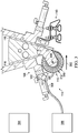
Figure 3 , an illustration of a cross-sectional view of a composite manufacturing system is depicted in accordance with an illustrative embodiment. A cross sectional view offiber placement head 108 from is shown along lines 3-3 inFigure 1 .Figure 3 illustrates an example of physical implementations of components withincomposite manufacturing system 202 shown in block form inFigure 2 . - As depicted,
fiber placement head 108 moves in the direction ofarrow 300 to placecomposite material 116 ontosubstrate 118. Asfiber placement head 108 moves,temperature regulation system 114 monitors and controls the temperature ofcompaction roller 112. - In this illustrative example,
temperature regulation system 114 comprisestemperature sensor 302,controller 304,cooling system 306, andsupply line 308.Cooling system 306 is a chiller that supplies cooled air tocompaction roller 212 throughsupply line 308 in this illustrative example. Cooled air is dissipated out ofcompaction roller 112 in the direction ofarrow 309. - In other illustrative examples, cooled liquid may flow through
supply line 308. Such liquid would then flow throughcompaction roller 112 and be redirected back tocooling system 306. -
Temperature sensor 302 continuously monitors the temperature onsurface 310 of compaction roller 312 asfiber placement head 108 moves along its path. The flow of air throughsupply line 308 is adjusted bycontroller 304 as the temperature ofsurface 310 ofcompaction roller 112 changes. - Turning now to
Figure 4 , another illustration a cross-sectional view of a composite manufacturing system is depicted in accordance with an illustrative embodiment.Figure 4 also illustrates an example of physical implementations of components withincomposite manufacturing system 202 shown in block form inFigure 2 . - As illustrated,
chilled roller 400 has been added tofiber placement head 108.Chilled roller 400 is in conductive contact withcompaction roller 112.Supply line 308 has been removed.Supply line 402 directs cooled air and/or cooled liquid tochilled roller 400 such thatchilled roller 400 decreases the temperature ofsurface 310 ofcompaction roller 112 through conduction. - In
Figure 5 , yet another illustration of a cross-sectional view of a composite manufacturing environment is depicted in accordance with an illustrative embodiment. In this illustrative example,supply line 308 supplies cooled air from coolingsystem 306 tocompaction roller 112. At substantially the same time, cooled air and/or cooled liquid flows throughsupply line 402 from coolingsystem 306 tochilled roller 400.Controller 304 may adjust the flow of fluid through at least one ofsupply line 308 andsupply line 402 to bring the temperature ofsurface 310 ofcompaction roller 112 below the threshold temperature. - Turning next to
Figure 6 , an illustration of a cross-sectional view of a roller in a composite manufacturing system is depicted in accordance with an illustrative embodiment. A more-detailed cross-sectional view ofchilled roller 400 is shown. - As depicted,
chilled roller 400 hascore 600 andchannels 602.Channels 602 direct cooled fluid through chilledroller 400.Channels 602 may be formed as part ofchilled roller 400. Althoughchannels 602 are shown with reference tochilled roller 400 in this figure,compaction roller 112 may have channels as well, depending on the particular implementation. - The different components shown in
Figure 1 andFigures 3 -6 may be combined with components inFigure 2 , used with components inFigure 2 , or a combination of the two. Additionally, some of the components inFigure 1 andFigures 3 -6 may be illustrative examples of how components shown in block form inFigure 2 may be implemented as physical structures. - Other configurations for
composite manufacturing system 100 may be implemented other than those shown inFigures 1 and3 -6. For instance, although only one temperature sensor and one chiller are shown inFigures 3-6 , two sensors, five sensors, or some other number of sensors or chillers may be implemented intemperature regulation system 114. Each temperature sensor communicates withcontroller 304. In other illustrative examples, one or more ofcompaction roller 112 orchilled roller 400 may be completely or partially hollow. In still other illustrative examples, more than two supply lines may supply cooled fluid to different areas in one or more of the rollers. - With reference next to
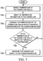
Figure 7 , an illustration of a flowchart of a process for regulating a temperature of a compaction roller in a composite manufacturing system is depicted in accordance with an illustrative embodiment. The method depicted inFigure 7 may be used withtemperature regulation system 216 to regulatetemperature 222 ofcompaction roller 212 inFigure 2 . - The process begins by sensing a temperature of the compaction roller (operation 700). Next, the process sends the temperature information to the controller (operation 702). The controller compares the temperature of the compaction roller with a threshold temperature for the compaction roller (operation 704). The controller then determines whether the temperature of the compaction roller is above the threshold temperature (operation 706). If the temperature of the compaction roller is not above the threshold temperature, the process returns to
operation 700. If the temperature of the compaction roller is above the threshold temperature, the process increases the cooled fluid supply to the compaction roller (operation 708), with the process returning tooperation 700 thereafter. In this manner,temperature regulation system 216 actively regulatestemperature 222 ofcompaction roller 212. Regulation may include reducing or increasing the flow of cooled fluid or shutting off the cooling system completely. - Turning now to
Figure 8 , an illustration of a flowchart of a process for manufacturing a composite structure for an aircraft is depicted in accordance with an illustrative embodiment. The method depicted inFigure 8 may be used withcomposite manufacturing system 202 to formcomposite structure 204 inFigure 2 . - The process begins by positioning composite material relative to a substrate (operation 800). Next, the composite material is heated as the fiber placement head moves along the substrate (operation 802). A compaction roller applies pressure to the heated composite material and the substrate (operation 804).
- Thereafter, a temperature of the compaction roller is determined (operation 806). The process then communicates the temperature information to a controller (operation 808).
- The process next determines whether the temperature of the compaction roller is above a threshold temperature (operation 810). If the temperature of the compaction roller is not above the threshold temperature, the process returns to
operation 806. If the temperature of the compaction roller is above the threshold temperature, the compaction roller is cooled until the temperature is below the threshold temperature (operation 812), with the process returning tooperation 806 thereafter. - The flowcharts and block diagrams in the different depicted illustrative embodiments illustrate the architecture, functionality, and operation of some possible implementations of apparatuses and methods in an illustrative embodiment. In this regard, each block in the flowcharts or block diagrams may represent a module, a segment, a function, and/or a portion of an operation or step.
- Illustrative embodiments of the disclosure may be described in the context of aircraft manufacturing and
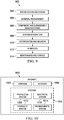
service method 900 as shown inFigure 9 andaircraft 1000 as shown inFigure 10 . Turning first toFigure 9 , an illustration of a block diagram of an aircraft manufacturing and service method is depicted in accordance with an illustrative embodiment. During pre-production, aircraft manufacturing andservice method 900 may include specification anddesign 902 ofaircraft 1000 inFigure 10 andmaterial procurement 904. - During production, component and
subassembly manufacturing 906 andsystem integration 908 ofaircraft 1000 inFigure 10 takes place. Thereafter,aircraft 1000 inFigure 10 may go through certification anddelivery 910 in order to be placed inservice 912. While inservice 912 by a customer,aircraft 1000 inFigure 10 is scheduled for routine maintenance andservice 914, which may include modification, reconfiguration, refurbishment, and other maintenance or service. -
Composite structure 204 fromFigure 2 may be made usingcomposite manufacturing system 202 withtemperature regulation system 216 during component andsubassembly manufacturing 906. In addition, components withincomposite manufacturing system 202 may be used during routine maintenance andservice 914 as part of a modification, reconfiguration, or refurbishment ofaircraft 1000 inFigure 10 . - Each of the processes of aircraft manufacturing and
service method 900 may be performed or carried out by a system integrator, a third party, an operator, or some combination thereof. In these examples, the operator may be a customer. For the purposes of this description, a system integrator may include, without limitation, any number of aircraft manufacturers and major-system subcontractors; a third party may include, without limitation, any number of vendors, subcontractors, and suppliers, and an operator may be an airline, a leasing company, a military entity, a service organization, and so on. - With reference now to
Figure 10 , an illustration of a block diagram of an aircraft is depicted in which a composite structure made using an illustrative embodiment may be implemented. In this example,aircraft 1000 is produced by aircraft manufacturing andservice method 900 inFigure 9 and may includeframe 1002 with plurality ofsystems 1004 and interior 1006. Examples ofsystems 1004 include one or more ofpropulsion system 1008,electrical system 1010,hydraulic system 1012, andenvironmental system 1014. Any number of other systems may be included. Although an aerospace example is shown, different illustrative embodiments may be applied to other industries, such as the automotive industry. - Apparatuses and methods embodied herein may be employed during at least one of the stages of aircraft manufacturing and
service method 900 inFigure 9 . In one illustrative example, components or subassemblies produced in component andsubassembly manufacturing 906 inFigure 9 may be fabricated or manufactured in a manner similar to components or subassemblies produced whileaircraft 1000 is inservice 912 inFigure 9 . As yet another example, one or more apparatus embodiments, method embodiments, or a combination thereof may be utilized during production stages, such as component andsubassembly manufacturing 906 andsystem integration 908 inFigure 9 . One or more apparatus embodiments, method embodiments, or a combination thereof may be utilized whileaircraft 1000 is inservice 912, during maintenance andservice 914 inFigure 9 , or both. The use of a number of the different illustrative embodiments may substantially expedite the assembly ofaircraft 1000, reduce the cost ofaircraft 1000, or both expedite the assembly ofaircraft 1000 and reduce the cost ofaircraft 1000. - With the use of an illustrative embodiment, a composite manufacturing system can work more efficiently with less risk of going offline due to roller wrap from an over-heated compaction roller. As a result, composite structures are formed more quickly and with less rework than with currently used systems.
- The illustrative embodiments also have precision control cooling capabilities. Fluid supplies may be controlled through a system of valves and supply lines. Conduction cooling also provides a novel feature over currently used manufacturing systems. The controller can regulate the temperature of the compaction roller to quench the tows while under the compaction roller. Chilling the tow while under compaction pressure increases its strength and allows for more precise maneuvering in complex geometries with a reduced risk of wrinkling or puckering.
- When using thermoplastics, an illustrative embodiment provides protection for components within the fiber placement head. Controlling roller temperature helps prevent degradation of these components from excess heat, thus saving additional manufacturing costs and downtime.
- In some alternative implementations of an illustrative embodiment, the function or functions noted in the blocks may occur out of the order noted in the figures. For example, in some cases, two blocks shown in succession may be executed substantially concurrently, or the blocks may sometimes be performed in the reverse order, depending upon the functionality involved. Also, other blocks may be added, in addition to the illustrated blocks, in a flowchart or block diagram.
- The description of the different illustrative embodiments has been presented for purposes of illustration and description, and is not intended to be exhaustive or limited to the embodiments in the form disclosed. Many modifications and variations will be apparent to those of ordinary skill in the art. Further, different illustrative embodiments may provide different features as compared to other desirable embodiments. The embodiment or embodiments selected are chosen and described in order to best explain the principles of the embodiments, the practical application, and to enable others of ordinary skill in the art to understand the disclosure for various embodiments with various modifications as are suited to the particular use contemplated.
Claims (15)
- A composite manufacturing system (202) comprising:a fiber placement head (210);a compaction roller (212) associated with the fiber placement head (210); anda temperature regulation system (216) associated with the compaction roller (212) and configured to actively control a temperature (222) of the compaction roller (212), the temperature regulation system (216) comprising:a number of temperature sensors (228) configured to detect the temperature (222) of the compaction roller (212);a cooling system (232) associated with the compaction roller (212) and configured to cool the compaction roller (212); anda controller (230) in communication with the number of temperature sensors (228) and the cooling system (232), wherein the controller (230) is configured to regulate the cooling system (232) such that the temperature (222) of the compaction roller (212) is below a threshold temperature (224).
- The composite manufacturing system (202) of claim 1, wherein the cooling system (232) comprises:
a cooling device (236) configured to supply cooled air (238) into the compaction roller (212) until the temperature (222) of the compaction roller (212) is below the threshold temperature (224). - The composite manufacturing system (202) of claims 1-2, wherein the cooling system (232) comprises:
a cooling device (236) configured to supply cooled liquid (240) into the compaction roller (212) until the temperature (222) of the compaction roller (212) is below the threshold temperature (224). - The composite manufacturing system (202) of claims 1-3, wherein the cooling system (232) comprises:
a chilled roller (242) in conductive contact with the compaction roller (212)optionally,.
wherein the cooling system (232) further comprises:
a cooling device (236) configured to supply at least one of cooled air (238) or cooled liquid (240) to the chilled roller (242). - The composite manufacturing system (202) of claim 4, wherein the chilled roller (242) comprises:
a number of channels (246) configured to direct at least one of cooled air (238) or cooled liquid (240) through the chilled roller (242). - The composite manufacturing system (202) of claims 1-5, wherein the compaction roller (212) comprises:
a number of channels (244) configured to direct at least one of cooled air (238) or cooled liquid (240) through the compaction roller (212). - The composite manufacturing system (202) of claims 1-6, wherein the controller (230) is configured to provide predictive cooling (248) for the compaction roller (212).
- The composite manufacturing system (202) of claims 1-7, wherein the cooling system (232) is configured to quench composite material (218) as the composite material (218) is applied by the compaction roller (212) to a substrate (220) to prevent undesired inconsistencies (226) from forming in the composite material (218).
- A method for regulating a temperature (222) of a compaction roller (212) in a composite manufacturing system (202), the method comprising:sensing the temperature (222) of the compaction roller (212);determining whether the temperature (222) of the compaction roller (212) is below a threshold temperature (224); andcooling the compaction roller (212) until the temperature (222) of the compaction roller (212) is below the threshold temperature (224).
- The method of claim 9, wherein cooling the compaction roller (212) comprises:
supplying cooled air (238) through the compaction roller (212) until the temperature (222) of the compaction roller (212) is below the threshold temperature (224). - The method of claims 9-10, wherein cooling the compaction roller (212) comprises:
supplying at least one of cooled air (238) or cooled liquid (240) to a chilled roller (242) in conductive contact with the compaction roller (212) until the temperature (222) of the compaction roller (212) is below the threshold temperature (224). - The method of claims 9-11, wherein cooling the compaction roller (212) comprises:supplying cooled air (238) to the compaction roller (212); andsupplying at least one of the cooled air (238) or cooled liquid (240) to a chilled roller (242) in conductive contact with the compaction roller (212).
- The method of claims 9-12 further comprising:
controlling a flow of at least one of cooled air (238) or cooled liquid (240) through the compaction roller (212) to provide predictive cooling (248) for the compaction roller (212). - The method of claims 9-13, wherein cooling the compaction roller (212) comprises:
controlling a flow of cooled air (238) through a number of channels (244) in the compaction roller (212). - The method of claims 9-14, wherein cooling the compaction roller (212) comprises:
controlling a flow of cooled air (238) through a number of channels (246) in a chilled roller (242), wherein the chilled roller (242) is in conductive contact with the compaction roller (212).
Applications Claiming Priority (2)
| Application Number | Priority Date | Filing Date | Title |
|---|---|---|---|
| US201962812008P | 2019-02-28 | 2019-02-28 | |
| US16/384,103 US11214022B2 (en) | 2019-02-28 | 2019-04-15 | Active cooling system for manufacturing composite structures |
Publications (2)
| Publication Number | Publication Date |
|---|---|
| EP3702141A1 true EP3702141A1 (en) | 2020-09-02 |
| EP3702141B1 EP3702141B1 (en) | 2023-07-26 |
Family
ID=69167663
Family Applications (1)
| Application Number | Title | Priority Date | Filing Date |
|---|---|---|---|
| EP20151618.4A Active EP3702141B1 (en) | 2019-02-28 | 2020-01-14 | Active cooling system for manufacturing composite structures |
Country Status (4)
| Country | Link |
|---|---|
| US (2) | US11214022B2 (en) |
| EP (1) | EP3702141B1 (en) |
| JP (1) | JP7448351B2 (en) |
| CN (1) | CN111619139B (en) |
Cited By (3)
| Publication number | Priority date | Publication date | Assignee | Title |
|---|---|---|---|---|
| CN114594811A (en) * | 2020-12-03 | 2022-06-07 | 上海飞机制造有限公司 | Temperature adjusting method, device, equipment and storage medium in material laying process |
| EP4134225A1 (en) * | 2021-08-12 | 2023-02-15 | The Boeing Company | Method and system for in-process monitoring of a compaction roller of a composite layup machine |
| CN119871949A (en) * | 2025-03-25 | 2025-04-25 | 杭州艾美依航空制造装备有限公司 | Compression device and wire laying head |
Families Citing this family (4)
| Publication number | Priority date | Publication date | Assignee | Title |
|---|---|---|---|---|
| US11911965B2 (en) * | 2021-08-12 | 2024-02-27 | Northrop Grumman Systems Corporation | Ultrasonic consolidation of continuous filament materials for additive manufacturing |
| DE102023113507A1 (en) * | 2023-05-23 | 2024-11-28 | Deutsches Zentrum für Luft- und Raumfahrt e.V. | Consolidation device and device for continuous ultrasonic welding |
| US12552112B2 (en) | 2024-02-08 | 2026-02-17 | General Electric Company | Automated fiber placement assembly |
| CN121200462B (en) * | 2025-11-27 | 2026-02-13 | 江西昌兴航空装备股份有限公司 | An automated layup method for thermoplastic composites based on dynamic thermal management. |
Citations (6)
| Publication number | Priority date | Publication date | Assignee | Title |
|---|---|---|---|---|
| US5700347A (en) * | 1996-01-11 | 1997-12-23 | The Boeing Company | Thermoplastic multi-tape application head |
| US20080093026A1 (en) * | 2006-10-24 | 2008-04-24 | Niko Naumann | Device for pressing a tape |
| FR2996491A1 (en) * | 2012-10-08 | 2014-04-11 | Europ Aeronautic Defence Ans Space Company Eads France | PROCESS FOR PRODUCING THERMOSETTING COMPOSITE PARTS BY DRAPING PREIMPREGNE MATERIAL |
| US20140190629A1 (en) * | 2013-01-04 | 2014-07-10 | Alliant Techsystems Inc. | Induction heating compaction system |
| US9080024B2 (en) * | 2012-11-09 | 2015-07-14 | Airbus Helicopters Deutschland GmbH | Heat control system for consolidation roller |
| US20180111341A1 (en) * | 2015-04-01 | 2018-04-26 | Coriolis Composites | Fiber application head with a specific application roll |
Family Cites Families (9)
| Publication number | Priority date | Publication date | Assignee | Title |
|---|---|---|---|---|
| DE204880C (en) | ||||
| DD204880B1 (en) * | 1982-05-13 | 1988-09-07 | Textima Veb K | DEVICE FOR COILING FOIL WEBS, ESPECIALLY FOR PLAST PROCESSING MACHINES |
| US5110395A (en) | 1989-12-04 | 1992-05-05 | Cincinnati Milacron Inc. | Fiber placement head |
| AT505845B1 (en) * | 2004-04-28 | 2009-05-15 | Hehenberger Gerhard | ARRANGEMENT WITH A GRANULAR HEAD OF AN EXTRUDER |
| US7731816B2 (en) * | 2006-02-16 | 2010-06-08 | Ingersoll Machine Tools, Inc. | System and method for heating carbon fiber using infrared radiation in a fiber placement machine |
| FR2948058B1 (en) * | 2009-07-17 | 2011-07-22 | Coriolis Composites | FIBER APPLICATION MACHINE COMPRISING A FLEXIBLE COMPACTION ROLL WITH THERMAL CONTROL SYSTEM |
| EP2788172A1 (en) * | 2011-12-07 | 2014-10-15 | E. I. Du Pont de Nemours and Company | Composite article made with unidirectional fiber reinforced tape |
| US11642860B2 (en) * | 2017-02-13 | 2023-05-09 | The Boeing Company | Method of making thermoplastic composite structures and prepreg tape used therein |
| US10525638B2 (en) * | 2017-08-29 | 2020-01-07 | The Boeing Company | Heater system for fiber placement machine |
-
2019
- 2019-04-15 US US16/384,103 patent/US11214022B2/en active Active
- 2019-12-19 JP JP2019229273A patent/JP7448351B2/en active Active
-
2020
- 2020-01-14 EP EP20151618.4A patent/EP3702141B1/en active Active
- 2020-02-17 CN CN202010097694.0A patent/CN111619139B/en active Active
-
2021
- 2021-11-19 US US17/455,808 patent/US11577476B2/en active Active
Patent Citations (6)
| Publication number | Priority date | Publication date | Assignee | Title |
|---|---|---|---|---|
| US5700347A (en) * | 1996-01-11 | 1997-12-23 | The Boeing Company | Thermoplastic multi-tape application head |
| US20080093026A1 (en) * | 2006-10-24 | 2008-04-24 | Niko Naumann | Device for pressing a tape |
| FR2996491A1 (en) * | 2012-10-08 | 2014-04-11 | Europ Aeronautic Defence Ans Space Company Eads France | PROCESS FOR PRODUCING THERMOSETTING COMPOSITE PARTS BY DRAPING PREIMPREGNE MATERIAL |
| US9080024B2 (en) * | 2012-11-09 | 2015-07-14 | Airbus Helicopters Deutschland GmbH | Heat control system for consolidation roller |
| US20140190629A1 (en) * | 2013-01-04 | 2014-07-10 | Alliant Techsystems Inc. | Induction heating compaction system |
| US20180111341A1 (en) * | 2015-04-01 | 2018-04-26 | Coriolis Composites | Fiber application head with a specific application roll |
Cited By (5)
| Publication number | Priority date | Publication date | Assignee | Title |
|---|---|---|---|---|
| CN114594811A (en) * | 2020-12-03 | 2022-06-07 | 上海飞机制造有限公司 | Temperature adjusting method, device, equipment and storage medium in material laying process |
| CN114594811B (en) * | 2020-12-03 | 2023-08-25 | 上海飞机制造有限公司 | Temperature adjustment method, device, equipment and storage medium in material laying process |
| EP4134225A1 (en) * | 2021-08-12 | 2023-02-15 | The Boeing Company | Method and system for in-process monitoring of a compaction roller of a composite layup machine |
| US11685130B2 (en) | 2021-08-12 | 2023-06-27 | The Boeing Company | Method and system for in-process monitoring of a compaction roller of a composite layup machine |
| CN119871949A (en) * | 2025-03-25 | 2025-04-25 | 杭州艾美依航空制造装备有限公司 | Compression device and wire laying head |
Also Published As
| Publication number | Publication date |
|---|---|
| US20200276774A1 (en) | 2020-09-03 |
| JP7448351B2 (en) | 2024-03-12 |
| JP2020138537A (en) | 2020-09-03 |
| US11214022B2 (en) | 2022-01-04 |
| EP3702141B1 (en) | 2023-07-26 |
| CN111619139B (en) | 2023-06-20 |
| US20220072815A1 (en) | 2022-03-10 |
| CN111619139A (en) | 2020-09-04 |
| US11577476B2 (en) | 2023-02-14 |
Similar Documents
| Publication | Publication Date | Title |
|---|---|---|
| US11577476B2 (en) | Active cooling system for manufacturing composite structures | |
| EP3772406A1 (en) | Induction welding for thermoplastic composite parts | |
| EP3772404B1 (en) | Induction welding using a heat sink and/or cooling | |
| JP5801576B2 (en) | Method and apparatus for joining composite structural members using a thermal spreader | |
| US11524467B2 (en) | Induction welding using a heat sink and/or cooling | |
| EP3785885B1 (en) | Induction welding using a heat sink | |
| US11358344B2 (en) | Induction welding using a heat sink and/or cooling | |
| US9669579B2 (en) | Aircraft skin attachment system | |
| US11351738B2 (en) | Induction welding using a heat sink and/or cooling | |
| US11292204B2 (en) | Induction welding using a heat sink and/or cooling | |
| US20210039328A1 (en) | Induction welding using a heat sink and/or cooling | |
| US20160290724A1 (en) | Application system for applying a coating agent | |
| EP4212314B1 (en) | Method and system for welding thermoplastic panels | |
| US8029644B2 (en) | Controlled temperature scrap removal for tape process |
Legal Events
| Date | Code | Title | Description |
|---|---|---|---|
| PUAI | Public reference made under article 153(3) epc to a published international application that has entered the european phase |
Free format text: ORIGINAL CODE: 0009012 |
|
| STAA | Information on the status of an ep patent application or granted ep patent |
Free format text: STATUS: THE APPLICATION HAS BEEN PUBLISHED |
|
| AK | Designated contracting states |
Kind code of ref document: A1 Designated state(s): AL AT BE BG CH CY CZ DE DK EE ES FI FR GB GR HR HU IE IS IT LI LT LU LV MC MK MT NL NO PL PT RO RS SE SI SK SM TR |
|
| AX | Request for extension of the european patent |
Extension state: BA ME |
|
| STAA | Information on the status of an ep patent application or granted ep patent |
Free format text: STATUS: REQUEST FOR EXAMINATION WAS MADE |
|
| 17P | Request for examination filed |
Effective date: 20210301 |
|
| RBV | Designated contracting states (corrected) |
Designated state(s): AL AT BE BG CH CY CZ DE DK EE ES FI FR GB GR HR HU IE IS IT LI LT LU LV MC MK MT NL NO PL PT RO RS SE SI SK SM TR |
|
| STAA | Information on the status of an ep patent application or granted ep patent |
Free format text: STATUS: EXAMINATION IS IN PROGRESS |
|
| 17Q | First examination report despatched |
Effective date: 20211108 |
|
| GRAP | Despatch of communication of intention to grant a patent |
Free format text: ORIGINAL CODE: EPIDOSNIGR1 |
|
| STAA | Information on the status of an ep patent application or granted ep patent |
Free format text: STATUS: GRANT OF PATENT IS INTENDED |
|
| RIC1 | Information provided on ipc code assigned before grant |
Ipc: B29C 70/54 20060101ALI20230118BHEP Ipc: B29C 35/16 20060101ALI20230118BHEP Ipc: B29L 31/30 20060101ALI20230118BHEP Ipc: B29C 70/38 20060101AFI20230118BHEP |
|
| INTG | Intention to grant announced |
Effective date: 20230222 |
|
| RAP3 | Party data changed (applicant data changed or rights of an application transferred) |
Owner name: THE BOEING COMPANY |
|
| GRAS | Grant fee paid |
Free format text: ORIGINAL CODE: EPIDOSNIGR3 |
|
| GRAA | (expected) grant |
Free format text: ORIGINAL CODE: 0009210 |
|
| STAA | Information on the status of an ep patent application or granted ep patent |
Free format text: STATUS: THE PATENT HAS BEEN GRANTED |
|
| AK | Designated contracting states |
Kind code of ref document: B1 Designated state(s): AL AT BE BG CH CY CZ DE DK EE ES FI FR GB GR HR HU IE IS IT LI LT LU LV MC MK MT NL NO PL PT RO RS SE SI SK SM TR |
|
| P01 | Opt-out of the competence of the unified patent court (upc) registered |
Effective date: 20230616 |
|
| REG | Reference to a national code |
Ref country code: CH Ref legal event code: EP |
|
| REG | Reference to a national code |
Ref country code: IE Ref legal event code: FG4D |
|
| REG | Reference to a national code |
Ref country code: DE Ref legal event code: R096 Ref document number: 602020014250 Country of ref document: DE |
|
| REG | Reference to a national code |
Ref country code: LT Ref legal event code: MG9D |
|
| REG | Reference to a national code |
Ref country code: NL Ref legal event code: MP Effective date: 20230726 |
|
| REG | Reference to a national code |
Ref country code: AT Ref legal event code: MK05 Ref document number: 1591503 Country of ref document: AT Kind code of ref document: T Effective date: 20230726 |
|
| PG25 | Lapsed in a contracting state [announced via postgrant information from national office to epo] |
Ref country code: NL Free format text: LAPSE BECAUSE OF FAILURE TO SUBMIT A TRANSLATION OF THE DESCRIPTION OR TO PAY THE FEE WITHIN THE PRESCRIBED TIME-LIMIT Effective date: 20230726 |
|
| PG25 | Lapsed in a contracting state [announced via postgrant information from national office to epo] |
Ref country code: GR Free format text: LAPSE BECAUSE OF FAILURE TO SUBMIT A TRANSLATION OF THE DESCRIPTION OR TO PAY THE FEE WITHIN THE PRESCRIBED TIME-LIMIT Effective date: 20231027 |
|
| PG25 | Lapsed in a contracting state [announced via postgrant information from national office to epo] |
Ref country code: IS Free format text: LAPSE BECAUSE OF FAILURE TO SUBMIT A TRANSLATION OF THE DESCRIPTION OR TO PAY THE FEE WITHIN THE PRESCRIBED TIME-LIMIT Effective date: 20231126 |
|
| PG25 | Lapsed in a contracting state [announced via postgrant information from national office to epo] |
Ref country code: SE Free format text: LAPSE BECAUSE OF FAILURE TO SUBMIT A TRANSLATION OF THE DESCRIPTION OR TO PAY THE FEE WITHIN THE PRESCRIBED TIME-LIMIT Effective date: 20230726 Ref country code: RS Free format text: LAPSE BECAUSE OF FAILURE TO SUBMIT A TRANSLATION OF THE DESCRIPTION OR TO PAY THE FEE WITHIN THE PRESCRIBED TIME-LIMIT Effective date: 20230726 Ref country code: PT Free format text: LAPSE BECAUSE OF FAILURE TO SUBMIT A TRANSLATION OF THE DESCRIPTION OR TO PAY THE FEE WITHIN THE PRESCRIBED TIME-LIMIT Effective date: 20231127 Ref country code: NO Free format text: LAPSE BECAUSE OF FAILURE TO SUBMIT A TRANSLATION OF THE DESCRIPTION OR TO PAY THE FEE WITHIN THE PRESCRIBED TIME-LIMIT Effective date: 20231026 Ref country code: LV Free format text: LAPSE BECAUSE OF FAILURE TO SUBMIT A TRANSLATION OF THE DESCRIPTION OR TO PAY THE FEE WITHIN THE PRESCRIBED TIME-LIMIT Effective date: 20230726 Ref country code: LT Free format text: LAPSE BECAUSE OF FAILURE TO SUBMIT A TRANSLATION OF THE DESCRIPTION OR TO PAY THE FEE WITHIN THE PRESCRIBED TIME-LIMIT Effective date: 20230726 Ref country code: IS Free format text: LAPSE BECAUSE OF FAILURE TO SUBMIT A TRANSLATION OF THE DESCRIPTION OR TO PAY THE FEE WITHIN THE PRESCRIBED TIME-LIMIT Effective date: 20231126 Ref country code: HR Free format text: LAPSE BECAUSE OF FAILURE TO SUBMIT A TRANSLATION OF THE DESCRIPTION OR TO PAY THE FEE WITHIN THE PRESCRIBED TIME-LIMIT Effective date: 20230726 Ref country code: GR Free format text: LAPSE BECAUSE OF FAILURE TO SUBMIT A TRANSLATION OF THE DESCRIPTION OR TO PAY THE FEE WITHIN THE PRESCRIBED TIME-LIMIT Effective date: 20231027 Ref country code: FI Free format text: LAPSE BECAUSE OF FAILURE TO SUBMIT A TRANSLATION OF THE DESCRIPTION OR TO PAY THE FEE WITHIN THE PRESCRIBED TIME-LIMIT Effective date: 20230726 Ref country code: AT Free format text: LAPSE BECAUSE OF FAILURE TO SUBMIT A TRANSLATION OF THE DESCRIPTION OR TO PAY THE FEE WITHIN THE PRESCRIBED TIME-LIMIT Effective date: 20230726 |
|
| PG25 | Lapsed in a contracting state [announced via postgrant information from national office to epo] |
Ref country code: PL Free format text: LAPSE BECAUSE OF FAILURE TO SUBMIT A TRANSLATION OF THE DESCRIPTION OR TO PAY THE FEE WITHIN THE PRESCRIBED TIME-LIMIT Effective date: 20230726 |
|
| PG25 | Lapsed in a contracting state [announced via postgrant information from national office to epo] |
Ref country code: ES Free format text: LAPSE BECAUSE OF FAILURE TO SUBMIT A TRANSLATION OF THE DESCRIPTION OR TO PAY THE FEE WITHIN THE PRESCRIBED TIME-LIMIT Effective date: 20230726 |
|
| REG | Reference to a national code |
Ref country code: DE Ref legal event code: R097 Ref document number: 602020014250 Country of ref document: DE |
|
| PG25 | Lapsed in a contracting state [announced via postgrant information from national office to epo] |
Ref country code: SM Free format text: LAPSE BECAUSE OF FAILURE TO SUBMIT A TRANSLATION OF THE DESCRIPTION OR TO PAY THE FEE WITHIN THE PRESCRIBED TIME-LIMIT Effective date: 20230726 Ref country code: RO Free format text: LAPSE BECAUSE OF FAILURE TO SUBMIT A TRANSLATION OF THE DESCRIPTION OR TO PAY THE FEE WITHIN THE PRESCRIBED TIME-LIMIT Effective date: 20230726 Ref country code: ES Free format text: LAPSE BECAUSE OF FAILURE TO SUBMIT A TRANSLATION OF THE DESCRIPTION OR TO PAY THE FEE WITHIN THE PRESCRIBED TIME-LIMIT Effective date: 20230726 Ref country code: EE Free format text: LAPSE BECAUSE OF FAILURE TO SUBMIT A TRANSLATION OF THE DESCRIPTION OR TO PAY THE FEE WITHIN THE PRESCRIBED TIME-LIMIT Effective date: 20230726 Ref country code: DK Free format text: LAPSE BECAUSE OF FAILURE TO SUBMIT A TRANSLATION OF THE DESCRIPTION OR TO PAY THE FEE WITHIN THE PRESCRIBED TIME-LIMIT Effective date: 20230726 Ref country code: CZ Free format text: LAPSE BECAUSE OF FAILURE TO SUBMIT A TRANSLATION OF THE DESCRIPTION OR TO PAY THE FEE WITHIN THE PRESCRIBED TIME-LIMIT Effective date: 20230726 Ref country code: SK Free format text: LAPSE BECAUSE OF FAILURE TO SUBMIT A TRANSLATION OF THE DESCRIPTION OR TO PAY THE FEE WITHIN THE PRESCRIBED TIME-LIMIT Effective date: 20230726 |
|
| PG25 | Lapsed in a contracting state [announced via postgrant information from national office to epo] |
Ref country code: IT Free format text: LAPSE BECAUSE OF FAILURE TO SUBMIT A TRANSLATION OF THE DESCRIPTION OR TO PAY THE FEE WITHIN THE PRESCRIBED TIME-LIMIT Effective date: 20230726 |
|
| PLBE | No opposition filed within time limit |
Free format text: ORIGINAL CODE: 0009261 |
|
| STAA | Information on the status of an ep patent application or granted ep patent |
Free format text: STATUS: NO OPPOSITION FILED WITHIN TIME LIMIT |
|
| 26N | No opposition filed |
Effective date: 20240429 |
|
| PG25 | Lapsed in a contracting state [announced via postgrant information from national office to epo] |
Ref country code: SI Free format text: LAPSE BECAUSE OF FAILURE TO SUBMIT A TRANSLATION OF THE DESCRIPTION OR TO PAY THE FEE WITHIN THE PRESCRIBED TIME-LIMIT Effective date: 20230726 |
|
| PG25 | Lapsed in a contracting state [announced via postgrant information from national office to epo] |
Ref country code: MC Free format text: LAPSE BECAUSE OF FAILURE TO SUBMIT A TRANSLATION OF THE DESCRIPTION OR TO PAY THE FEE WITHIN THE PRESCRIBED TIME-LIMIT Effective date: 20230726 |
|
| PG25 | Lapsed in a contracting state [announced via postgrant information from national office to epo] |
Ref country code: MC Free format text: LAPSE BECAUSE OF FAILURE TO SUBMIT A TRANSLATION OF THE DESCRIPTION OR TO PAY THE FEE WITHIN THE PRESCRIBED TIME-LIMIT Effective date: 20230726 |
|
| REG | Reference to a national code |
Ref country code: CH Ref legal event code: PL |
|
| PG25 | Lapsed in a contracting state [announced via postgrant information from national office to epo] |
Ref country code: LU Free format text: LAPSE BECAUSE OF NON-PAYMENT OF DUE FEES Effective date: 20240114 |
|
| PG25 | Lapsed in a contracting state [announced via postgrant information from national office to epo] |
Ref country code: LU Free format text: LAPSE BECAUSE OF NON-PAYMENT OF DUE FEES Effective date: 20240114 |
|
| PG25 | Lapsed in a contracting state [announced via postgrant information from national office to epo] |
Ref country code: BE Free format text: LAPSE BECAUSE OF NON-PAYMENT OF DUE FEES Effective date: 20240131 |
|
| PG25 | Lapsed in a contracting state [announced via postgrant information from national office to epo] |
Ref country code: CH Free format text: LAPSE BECAUSE OF NON-PAYMENT OF DUE FEES Effective date: 20240131 |
|
| PG25 | Lapsed in a contracting state [announced via postgrant information from national office to epo] |
Ref country code: CH Free format text: LAPSE BECAUSE OF NON-PAYMENT OF DUE FEES Effective date: 20240131 Ref country code: BE Free format text: LAPSE BECAUSE OF NON-PAYMENT OF DUE FEES Effective date: 20240131 |
|
| REG | Reference to a national code |
Ref country code: BE Ref legal event code: MM Effective date: 20240131 |
|
| PG25 | Lapsed in a contracting state [announced via postgrant information from national office to epo] |
Ref country code: BG Free format text: LAPSE BECAUSE OF FAILURE TO SUBMIT A TRANSLATION OF THE DESCRIPTION OR TO PAY THE FEE WITHIN THE PRESCRIBED TIME-LIMIT Effective date: 20230726 |
|
| PG25 | Lapsed in a contracting state [announced via postgrant information from national office to epo] |
Ref country code: BG Free format text: LAPSE BECAUSE OF FAILURE TO SUBMIT A TRANSLATION OF THE DESCRIPTION OR TO PAY THE FEE WITHIN THE PRESCRIBED TIME-LIMIT Effective date: 20230726 |
|
| PG25 | Lapsed in a contracting state [announced via postgrant information from national office to epo] |
Ref country code: IE Free format text: LAPSE BECAUSE OF NON-PAYMENT OF DUE FEES Effective date: 20240114 |
|
| PG25 | Lapsed in a contracting state [announced via postgrant information from national office to epo] |
Ref country code: IE Free format text: LAPSE BECAUSE OF NON-PAYMENT OF DUE FEES Effective date: 20240114 |
|
| PG25 | Lapsed in a contracting state [announced via postgrant information from national office to epo] |
Ref country code: CY Free format text: LAPSE BECAUSE OF FAILURE TO SUBMIT A TRANSLATION OF THE DESCRIPTION OR TO PAY THE FEE WITHIN THE PRESCRIBED TIME-LIMIT; INVALID AB INITIO Effective date: 20200114 |
|
| PG25 | Lapsed in a contracting state [announced via postgrant information from national office to epo] |
Ref country code: HU Free format text: LAPSE BECAUSE OF FAILURE TO SUBMIT A TRANSLATION OF THE DESCRIPTION OR TO PAY THE FEE WITHIN THE PRESCRIBED TIME-LIMIT; INVALID AB INITIO Effective date: 20200114 |
|
| PG25 | Lapsed in a contracting state [announced via postgrant information from national office to epo] |
Ref country code: TR Free format text: LAPSE BECAUSE OF FAILURE TO SUBMIT A TRANSLATION OF THE DESCRIPTION OR TO PAY THE FEE WITHIN THE PRESCRIBED TIME-LIMIT Effective date: 20230726 |
|
| PGFP | Annual fee paid to national office [announced via postgrant information from national office to epo] |
Ref country code: GB Payment date: 20260127 Year of fee payment: 7 |
|
| PGFP | Annual fee paid to national office [announced via postgrant information from national office to epo] |
Ref country code: DE Payment date: 20260128 Year of fee payment: 7 |
|
| PGFP | Annual fee paid to national office [announced via postgrant information from national office to epo] |
Ref country code: FR Payment date: 20260126 Year of fee payment: 7 |