EP3702125A2 - Rubber extruder and method for extruding rubber - Google Patents
Rubber extruder and method for extruding rubber Download PDFInfo
- Publication number
- EP3702125A2 EP3702125A2 EP20159818.2A EP20159818A EP3702125A2 EP 3702125 A2 EP3702125 A2 EP 3702125A2 EP 20159818 A EP20159818 A EP 20159818A EP 3702125 A2 EP3702125 A2 EP 3702125A2
- Authority
- EP
- European Patent Office
- Prior art keywords
- unvulcanized rubber
- rubber
- extruding
- barrel
- screw
- Prior art date
- Legal status (The legal status is an assumption and is not a legal conclusion. Google has not performed a legal analysis and makes no representation as to the accuracy of the status listed.)
- Granted
Links
Images




Classifications
-
- B—PERFORMING OPERATIONS; TRANSPORTING
- B29—WORKING OF PLASTICS; WORKING OF SUBSTANCES IN A PLASTIC STATE IN GENERAL
- B29C—SHAPING OR JOINING OF PLASTICS; SHAPING OF MATERIAL IN A PLASTIC STATE, NOT OTHERWISE PROVIDED FOR; AFTER-TREATMENT OF THE SHAPED PRODUCTS, e.g. REPAIRING
- B29C48/00—Extrusion moulding, i.e. expressing the moulding material through a die or nozzle which imparts the desired form; Apparatus therefor
- B29C48/25—Component parts, details or accessories; Auxiliary operations
- B29C48/36—Means for plasticising or homogenising the moulding material or forcing it through the nozzle or die
- B29C48/395—Means for plasticising or homogenising the moulding material or forcing it through the nozzle or die using screws surrounded by a cooperating barrel, e.g. single screw extruders
- B29C48/397—Means for plasticising or homogenising the moulding material or forcing it through the nozzle or die using screws surrounded by a cooperating barrel, e.g. single screw extruders using a single screw
-
- B—PERFORMING OPERATIONS; TRANSPORTING
- B29—WORKING OF PLASTICS; WORKING OF SUBSTANCES IN A PLASTIC STATE IN GENERAL
- B29C—SHAPING OR JOINING OF PLASTICS; SHAPING OF MATERIAL IN A PLASTIC STATE, NOT OTHERWISE PROVIDED FOR; AFTER-TREATMENT OF THE SHAPED PRODUCTS, e.g. REPAIRING
- B29C48/00—Extrusion moulding, i.e. expressing the moulding material through a die or nozzle which imparts the desired form; Apparatus therefor
- B29C48/022—Extrusion moulding, i.e. expressing the moulding material through a die or nozzle which imparts the desired form; Apparatus therefor characterised by the choice of material
-
- B—PERFORMING OPERATIONS; TRANSPORTING
- B29—WORKING OF PLASTICS; WORKING OF SUBSTANCES IN A PLASTIC STATE IN GENERAL
- B29C—SHAPING OR JOINING OF PLASTICS; SHAPING OF MATERIAL IN A PLASTIC STATE, NOT OTHERWISE PROVIDED FOR; AFTER-TREATMENT OF THE SHAPED PRODUCTS, e.g. REPAIRING
- B29C48/00—Extrusion moulding, i.e. expressing the moulding material through a die or nozzle which imparts the desired form; Apparatus therefor
- B29C48/25—Component parts, details or accessories; Auxiliary operations
- B29C48/285—Feeding the extrusion material to the extruder
- B29C48/288—Feeding the extrusion material to the extruder in solid form, e.g. powder or granules
- B29C48/2888—Feeding the extrusion material to the extruder in solid form, e.g. powder or granules in thread form or in strip form, e.g. rubber strips
-
- B—PERFORMING OPERATIONS; TRANSPORTING
- B29—WORKING OF PLASTICS; WORKING OF SUBSTANCES IN A PLASTIC STATE IN GENERAL
- B29C—SHAPING OR JOINING OF PLASTICS; SHAPING OF MATERIAL IN A PLASTIC STATE, NOT OTHERWISE PROVIDED FOR; AFTER-TREATMENT OF THE SHAPED PRODUCTS, e.g. REPAIRING
- B29C48/00—Extrusion moulding, i.e. expressing the moulding material through a die or nozzle which imparts the desired form; Apparatus therefor
- B29C48/25—Component parts, details or accessories; Auxiliary operations
- B29C48/36—Means for plasticising or homogenising the moulding material or forcing it through the nozzle or die
- B29C48/50—Details of extruders
- B29C48/501—Extruder feed section
-
- B—PERFORMING OPERATIONS; TRANSPORTING
- B29—WORKING OF PLASTICS; WORKING OF SUBSTANCES IN A PLASTIC STATE IN GENERAL
- B29C—SHAPING OR JOINING OF PLASTICS; SHAPING OF MATERIAL IN A PLASTIC STATE, NOT OTHERWISE PROVIDED FOR; AFTER-TREATMENT OF THE SHAPED PRODUCTS, e.g. REPAIRING
- B29C48/00—Extrusion moulding, i.e. expressing the moulding material through a die or nozzle which imparts the desired form; Apparatus therefor
- B29C48/25—Component parts, details or accessories; Auxiliary operations
- B29C48/36—Means for plasticising or homogenising the moulding material or forcing it through the nozzle or die
- B29C48/50—Details of extruders
- B29C48/505—Screws
- B29C48/52—Screws with an outer diameter varying along the longitudinal axis, e.g. for obtaining different thread clearance
- B29C48/525—Conical screws
-
- B—PERFORMING OPERATIONS; TRANSPORTING
- B29—WORKING OF PLASTICS; WORKING OF SUBSTANCES IN A PLASTIC STATE IN GENERAL
- B29C—SHAPING OR JOINING OF PLASTICS; SHAPING OF MATERIAL IN A PLASTIC STATE, NOT OTHERWISE PROVIDED FOR; AFTER-TREATMENT OF THE SHAPED PRODUCTS, e.g. REPAIRING
- B29C48/00—Extrusion moulding, i.e. expressing the moulding material through a die or nozzle which imparts the desired form; Apparatus therefor
- B29C48/25—Component parts, details or accessories; Auxiliary operations
- B29C48/36—Means for plasticising or homogenising the moulding material or forcing it through the nozzle or die
- B29C48/50—Details of extruders
- B29C48/505—Screws
- B29C48/53—Screws having a varying channel depth, e.g. varying the diameter of the longitudinal screw trunk
-
- B—PERFORMING OPERATIONS; TRANSPORTING
- B29—WORKING OF PLASTICS; WORKING OF SUBSTANCES IN A PLASTIC STATE IN GENERAL
- B29C—SHAPING OR JOINING OF PLASTICS; SHAPING OF MATERIAL IN A PLASTIC STATE, NOT OTHERWISE PROVIDED FOR; AFTER-TREATMENT OF THE SHAPED PRODUCTS, e.g. REPAIRING
- B29C48/00—Extrusion moulding, i.e. expressing the moulding material through a die or nozzle which imparts the desired form; Apparatus therefor
- B29C48/25—Component parts, details or accessories; Auxiliary operations
- B29C48/36—Means for plasticising or homogenising the moulding material or forcing it through the nozzle or die
- B29C48/50—Details of extruders
- B29C48/505—Screws
- B29C48/535—Screws with thread pitch varying along the longitudinal axis
-
- B—PERFORMING OPERATIONS; TRANSPORTING
- B29—WORKING OF PLASTICS; WORKING OF SUBSTANCES IN A PLASTIC STATE IN GENERAL
- B29C—SHAPING OR JOINING OF PLASTICS; SHAPING OF MATERIAL IN A PLASTIC STATE, NOT OTHERWISE PROVIDED FOR; AFTER-TREATMENT OF THE SHAPED PRODUCTS, e.g. REPAIRING
- B29C48/00—Extrusion moulding, i.e. expressing the moulding material through a die or nozzle which imparts the desired form; Apparatus therefor
- B29C48/25—Component parts, details or accessories; Auxiliary operations
- B29C48/36—Means for plasticising or homogenising the moulding material or forcing it through the nozzle or die
- B29C48/50—Details of extruders
- B29C48/505—Screws
- B29C48/56—Screws having grooves or cavities other than the thread or the channel
-
- B—PERFORMING OPERATIONS; TRANSPORTING
- B29—WORKING OF PLASTICS; WORKING OF SUBSTANCES IN A PLASTIC STATE IN GENERAL
- B29C—SHAPING OR JOINING OF PLASTICS; SHAPING OF MATERIAL IN A PLASTIC STATE, NOT OTHERWISE PROVIDED FOR; AFTER-TREATMENT OF THE SHAPED PRODUCTS, e.g. REPAIRING
- B29C48/00—Extrusion moulding, i.e. expressing the moulding material through a die or nozzle which imparts the desired form; Apparatus therefor
- B29C48/25—Component parts, details or accessories; Auxiliary operations
- B29C48/36—Means for plasticising or homogenising the moulding material or forcing it through the nozzle or die
- B29C48/50—Details of extruders
- B29C48/505—Screws
- B29C48/59—Screws characterised by details of the thread, i.e. the shape of a single thread of the material-feeding screw
- B29C48/605—Screws characterised by details of the thread, i.e. the shape of a single thread of the material-feeding screw the thread being discontinuous
-
- B—PERFORMING OPERATIONS; TRANSPORTING
- B29—WORKING OF PLASTICS; WORKING OF SUBSTANCES IN A PLASTIC STATE IN GENERAL
- B29C—SHAPING OR JOINING OF PLASTICS; SHAPING OF MATERIAL IN A PLASTIC STATE, NOT OTHERWISE PROVIDED FOR; AFTER-TREATMENT OF THE SHAPED PRODUCTS, e.g. REPAIRING
- B29C48/00—Extrusion moulding, i.e. expressing the moulding material through a die or nozzle which imparts the desired form; Apparatus therefor
- B29C48/25—Component parts, details or accessories; Auxiliary operations
- B29C48/36—Means for plasticising or homogenising the moulding material or forcing it through the nozzle or die
- B29C48/50—Details of extruders
- B29C48/68—Barrels or cylinders
- B29C48/681—Barrels or cylinders for single screws
-
- B—PERFORMING OPERATIONS; TRANSPORTING
- B29—WORKING OF PLASTICS; WORKING OF SUBSTANCES IN A PLASTIC STATE IN GENERAL
- B29C—SHAPING OR JOINING OF PLASTICS; SHAPING OF MATERIAL IN A PLASTIC STATE, NOT OTHERWISE PROVIDED FOR; AFTER-TREATMENT OF THE SHAPED PRODUCTS, e.g. REPAIRING
- B29C48/00—Extrusion moulding, i.e. expressing the moulding material through a die or nozzle which imparts the desired form; Apparatus therefor
- B29C48/25—Component parts, details or accessories; Auxiliary operations
- B29C48/36—Means for plasticising or homogenising the moulding material or forcing it through the nozzle or die
- B29C48/50—Details of extruders
- B29C48/68—Barrels or cylinders
- B29C48/685—Barrels or cylinders characterised by their inner surfaces, e.g. having grooves, projections or threads
- B29C48/687—Barrels or cylinders characterised by their inner surfaces, e.g. having grooves, projections or threads having projections with a short length in the barrel direction, e.g. pins
-
- B—PERFORMING OPERATIONS; TRANSPORTING
- B29—WORKING OF PLASTICS; WORKING OF SUBSTANCES IN A PLASTIC STATE IN GENERAL
- B29C—SHAPING OR JOINING OF PLASTICS; SHAPING OF MATERIAL IN A PLASTIC STATE, NOT OTHERWISE PROVIDED FOR; AFTER-TREATMENT OF THE SHAPED PRODUCTS, e.g. REPAIRING
- B29C48/00—Extrusion moulding, i.e. expressing the moulding material through a die or nozzle which imparts the desired form; Apparatus therefor
- B29C48/25—Component parts, details or accessories; Auxiliary operations
- B29C48/36—Means for plasticising or homogenising the moulding material or forcing it through the nozzle or die
- B29C48/50—Details of extruders
- B29C48/505—Screws
- B29C48/58—Screws provided with seal ring elements, i.e. elements of generally circular and tapered shape for preventing the back flow of the melt
-
- B—PERFORMING OPERATIONS; TRANSPORTING
- B29—WORKING OF PLASTICS; WORKING OF SUBSTANCES IN A PLASTIC STATE IN GENERAL
- B29C—SHAPING OR JOINING OF PLASTICS; SHAPING OF MATERIAL IN A PLASTIC STATE, NOT OTHERWISE PROVIDED FOR; AFTER-TREATMENT OF THE SHAPED PRODUCTS, e.g. REPAIRING
- B29C48/00—Extrusion moulding, i.e. expressing the moulding material through a die or nozzle which imparts the desired form; Apparatus therefor
- B29C48/25—Component parts, details or accessories; Auxiliary operations
- B29C48/36—Means for plasticising or homogenising the moulding material or forcing it through the nozzle or die
- B29C48/50—Details of extruders
- B29C48/505—Screws
- B29C48/59—Screws characterised by details of the thread, i.e. the shape of a single thread of the material-feeding screw
- B29C48/595—Screws characterised by details of the thread, i.e. the shape of a single thread of the material-feeding screw the thread having non-uniform width
-
- B—PERFORMING OPERATIONS; TRANSPORTING
- B29—WORKING OF PLASTICS; WORKING OF SUBSTANCES IN A PLASTIC STATE IN GENERAL
- B29K—INDEXING SCHEME ASSOCIATED WITH SUBCLASSES B29B, B29C OR B29D, RELATING TO MOULDING MATERIALS OR TO MATERIALS FOR MOULDS, REINFORCEMENTS, FILLERS OR PREFORMED PARTS, e.g. INSERTS
- B29K2021/00—Use of unspecified rubbers as moulding material
- B29K2021/006—Thermosetting elastomers
Definitions
- a length of the compression section in an axial direction of the barrel is longer than a length of the dividing section in the axial direction.
- silane coupling agent it is not particularly limited, but can be employed, for example, sulfide-based, mercapto-based, vinyl-based, amino-based, glycidoxy-based, nitro-based, and chloro-based silane coupling agents.
- the silane coupling agent can include only a single kind, or two or more kinds which are to be mixed.
- unvulcanized rubber G is divided by the sets of plurality of pins 6A provided on an inner surface of the barrel 2.
- a protruding amount of the pins 6A may be adjusted easily based on viscosity of unvulcanized rubber G to be extruded, productivity of extrusion process of the unvulcanized rubber G can be improved.
- the unvulcanized rubber G is compressed using the screw 5 having a depth D of the channel 5c decreasing gradually toward the extruding direction A of the unvulcanized rubber G
- the compressing step S23 can make a rate of increase of pressure of the unvulcanized rubber G per unit time small.
- the compressing step S23 can compress the unvulcanized rubber G without increasing residual stress of the unvulcanized rubber G
- the dividing step S21 for example, divides the unvulcanized rubber G using the sets of a plurality of pins 6A in which the pitch P3 on the kneading section 7 side is smaller than the pitch P4 on the feeding portion 3 side.
- Such a dividing step S21 can divide the unvulcanized rubber G more finely in the downstream side in the extruding direction A, improving productivity of extruding process.
Landscapes
- Engineering & Computer Science (AREA)
- Mechanical Engineering (AREA)
- Extrusion Moulding Of Plastics Or The Like (AREA)
Abstract
Description
- The present invention relates to a rubber extruder for extruding unvulcanized rubber and a method for extruding unvulcanized rubber.
- Conventionally, rubber extruders which include barrels and screws arranged in the barrels have been known. For example, the following
Patent document 1 discloses a rubber component manufacturing device which includes a damming section provided halfway through a screw to prevent degradation of a low exothermic rubber component. - [Patent document 1] Japanese Unexamined Patent Application Publication
2015-013414 - Unfortunately, when high viscosity unvulcanized rubber is extruded using the rubber component manufacturing device as disclosed in
Patent document 1, productivity tends to be lowered. Thus, there is room for further improvement. - The present invention has been made in view of the above circumstances, and has a major object to provide a rubber extruder capable of improving quality and productivity of high viscosity unvulcanized rubber.
- In one aspect of the first invention, a rubber extruder includes a barrel, a feeding portion for feeding unvulcanized rubber to the interior of the barrel, and a screw for extruding the unvulcanized rubber fed in the interior of the barrel toward an extruding direction, the screw having at least one helically extending flight to define at least one helically extending channel; characterized in that
the interior of the barrel includes a dividing section for dividing the unvulcanized rubber, a kneading section for kneading the divided unvulcanized rubber locally, and a compression section for compressing the kneaded unvulcanized rubber toward the extruding direction, wherein the compression section is configured such that the screw therein has a volume of the channel decreasing gradually toward the extruding direction of the unvulcanized rubber. - In the first invention, it is preferable that a length of the compression section in an axial direction of the barrel is longer than a length of the dividing section in the axial direction.
- In one aspect of the second invention, a rubber extruder includes a barrel, a feeding portion for feeding unvulcanized rubber to the interior of the barrel, and a screw for extruding the unvulcanized rubber fed in the interior of the barrel toward an extruding direction, the screw having at least one helically extending flight to define at least one helically extending channel; characterized in that
the interior of the barrel includes a dividing section for dividing the unvulcanized rubber, a kneading section for kneading the divided unvulcanized rubber locally, and a compression section for compressing the kneaded unvulcanized rubber toward the extruding direction, wherein in the dividing section, the barrel is provided with one or more sets of plurality of pins. - In the second invention, it is preferable that three or more sets of plurality of pins are arranged in the axil direction of the barrel, and that with respect to arrangement pitches in the axial direction of the sets of plurality of pins, a pitch on the kneading section side is smaller than a pitch on the feeding portion side.
- In one aspect of the third invention, a rubber extruder includes a barrel, a feeding portion for feeding unvulcanized rubber to the interior of the barrel, and a screw for extruding the unvulcanized rubber fed in the interior of the barrel toward an extruding direction, the screw having at least one helically extending flight to define at least one helically extending channel; characterized in that
the interior of the barrel includes a dividing section for dividing the unvulcanized rubber, a kneading section for kneading the divided unvulcanized rubber locally, and a compression section for compressing the kneaded unvulcanized rubber toward the extruding direction, wherein the feeding portion includes a feeder for helping to supply the screw with the unvulcanized rubber. - In the third invention, it is preferable that the feeding portion includes a hopper provided on the barrel, and the feeder includes a gear mechanism disposed in the hopper.
- In the third invention, it is preferable that the feeder includes a wide flight pitch portion of the screw having a flight pitch greater than that of another portion of the screw.
- In the third invention, it is preferable that the feeder includes a low flight height portion of the screw having a flight height smaller than that of another portion of the screw.
- In any preceding inventions, it is preferable that the compression section is configured such that a depth of the channel of the screw decreases gradually toward the extruding direction.
- In any preceding inventions, it is preferable that the compression section is configured such that a flight pitch of the screw in the axial direction decreases gradually toward the extruding direction.
- In any preceding inventions, it is preferable that the screw in the kneading section further including a barrier flight extending from a portion of the flight to another portion of the flight.
- In any preceding inventions, it is preferable that the screw in the kneading section further including a cylindrical dam portion arranged coaxially with the screw.
- In one aspect of the fourth invention, a method for extruding rubber, the method includes a feeding step for feeding an interior of a barrel of a rubber extruder with unvulcanized rubber, and an extruding step for extruding the unvulcanized rubber fed in the barrel toward an extruding direction using a screw which includes at least one helically extending flight to define at least one helically extending channel; characterized in that
the extruding step includes a dividing step for dividing the unvulcanized rubber, a kneading step for kneading the divided unvulcanized rubber locally, and a compressing step for compressing the kneaded unvulcanized rubber toward the extruding direction, wherein the compressing step compresses the unvulcanized rubber using the screw configured such that the screw has a volume of the channel decreasing gradually toward the extruding direction. - In one aspect of the fifth invention, a method for extruding rubber, the method includes a feeding step for feeding an interior of a barrel of a rubber extruder with unvulcanized rubber, and an extruding step for extruding the unvulcanized rubber fed in the barrel toward an extruding direction using a screw which includes at least one helically extending flight to define at least one helically extending channel; characterized in that
the extruding step includes a dividing step for dividing the unvulcanized rubber, a kneading step for kneading the divided unvulcanized rubber locally, and a compressing step for compressing the kneaded unvulcanized rubber toward the extruding direction, wherein the dividing step divides the unvulcanized rubber using one or more sets of plurality of pins provided on the interior of the barrel. - In one aspect of the sixth invention, a method for extruding rubber, the method includes a feeding step for feeding an interior of a barrel of a rubber extruder with unvulcanized rubber, and an extruding step for extruding the unvulcanized rubber fed in the barrel toward an extruding direction using a screw which includes at least one helically extending flight to define at least one helically extending channel; characterized in that the extruding step includes a dividing step for dividing the unvulcanized rubber, a kneading step for kneading the divided unvulcanized rubber locally, and a compressing step for compressing the kneaded unvulcanized rubber toward the extruding direction, wherein the feeding step feeds the unvulcanized rubber using a feeder of the rubber extruder.
- The rubber extruder according to the present invention includes a barrel, a feeding portion for feeding unvulcanized rubber to the interior of the barrel, and a screw for extruding the unvulcanized rubber fed in the interior of the barrel toward an extruding direction, the screw having at least one helically extending flight to define at least one helically extending channel, characterized in that the interior of the barrel comprises a dividing section for dividing the unvulcanized rubber, a kneading section for kneading the divided unvulcanized rubber least locally, and a compression section for compressing the kneaded unvulcanized rubber toward the extruding direction.
- In the rubber extruder configured as such, the dividing section improves fluidity of unvulcanized rubber to promote heating and plasticization of the unvulcanized rubber, improving productivity of extrusion process. In addition, the kneading section of the rubber extruder can knead unvulcanized rubber uniformly even when an amount of unvulcanized rubber fed into the extruder varies. Further, the compression section of the rubber extruder makes it possible to merge the divided unvulcanized rubber without increasing residual stress thereof. Thus, the rubber extruder can extrude kneaded unvulcanized rubber uniformly into the required shape stably.
- In the rubber extruder according to one aspect of the present invention, the compression section is configured such that the screw therein has a channel volume of the flight decreasing gradually toward the extruding direction of unvulcanized rubber. The compression section configured as such makes it possible to merge the divided unvulcanized rubber without increasing residual stress thereof, improving quality of unvulcanized rubber to be extruded.
- In the rubber extruder according to another aspect of the present invention, the dividing section includes one or more sets of plurality of pins provided in the barrel. The dividing section as such, for example, enables to adjust a protruding amount of the pins easily according to viscosity of unvulcanized rubber, improving productivity of extrusion process.
- In the rubber extruder according to another aspect of the present invention, the feeding portion comprises a feeder for helping to supply the screw with unvulcanized rubber. The feeding portion as such enables to surely feed a continuous band shaped unvulcanized rubber into the barrel, reducing production loss due to miss feeding of unvulcanized rubber.
- Thus, the rubber extruder according to the present invention can improve quality and productivity of high viscosity unvulcanized rubber.
- The method for extruding rubber according to the present invention includes a feeding step for feeding an interior of a barrel of a rubber extruder with unvulcanized rubber, and an extruding step for extruding the unvulcanized rubber fed in the barrel toward an extruding direction using a screw having a flight, characterized in that the extruding step includes a dividing step for dividing the unvulcanized rubber, a kneading step for kneading the divided unvulcanized rubber locally, and a compressing step for compressing the kneaded unvulcanized rubber toward the extruding direction.
- In the method for extruding rubber as such, the dividing step improves fluidity of unvulcanized rubber to promote heating and plasticization of the unvulcanized rubber, improving productivity of extrusion process. In addition, the kneading step of the method for extruding rubber can knead unvulcanized rubber uniformly even when an amount of unvulcanized rubber fed into the extruder varies. Further, the compressing step of the rubber extruder makes it possible to merge the divided unvulcanized rubber without increasing residual stress thereof. Thus, the method for extruding rubber can extrude kneaded unvulcanized rubber uniformly into the required shape stably.
- In the method for extruding rubber according to one aspect of the present invention, the compressing step compresses the unvulcanized rubber using the screw configured such that the screw has a volume of the channel decreasing gradually toward the extruding direction of unvulcanized rubber. The compressing step as such makes it possible to merge the divided unvulcanized rubber without increasing residual stress thereof, improving quality of unvulcanized rubber to be extruded.
- In the method for extruding rubber according to another aspect of the present invention, the dividing step divides the unvulcanized rubber using one or more sets of plurality of pins provided on the interior of the barrel. In the dividing step as such, it enables to adjust a protruding amount of the pins easily according to viscosity of unvulcanized rubber, improving productivity of extrusion process.
- In the method for extruding rubber according to another aspect of the present invention, the feeding step feeds the unvulcanized rubber using a feeder of the rubber extruder. The feeding step as such enables to surely feed a continuous band shaped unvulcanized rubber into the barrel, reducing production loss due to miss feeding of unvulcanized rubber.
- Thus, the method for extruding rubber according to the present invention can improve quality and productivity of high viscosity unvulcanized rubber.
-
-
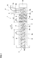
FIG. 1 is a cross-sectional view of a rubber extruder according to one embodiment of the present invention. -
FIG. 2 is a flowchart for explaining an embodiment of a method for extruding rubber according to one embodiment of the present invention. -
FIG. 3 is a flowchart of an extruding step. -
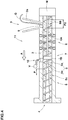
FIG. 4 is a cross-sectional view of the rubber extruder according to the second embodiment. -
FIG. 5 is a cross-sectional view of the rubber extruder according to the third embodiment. -
FIG. 6 is a cross-sectional view of the rubber extruder according to the fourth embodiment. -
FIG. 7 is a cross-sectional view of the rubber extruder according to the fifth embodiment. -
FIG. 8 is a cross-sectional view of the rubber extruder according to the sixth embodiment. - One or more embodiments of the present invention will be explained below with reference to the accompanying drawings.
-
FIG. 1 is a cross-sectional view of arubber extruder 1 according to one embodiment (first embodiment). As illustrated inFIG. 1 , therubber extruder 1 according to the present embodiment includes abarrel 2, a feedingportion 3 for feeding unvulcanized rubber G to the interior of thebarrel 2, and a discharging portion 4 for discharging unvulcanized rubber G in thebarrel 2. Therubber extruder 1 further includes ascrew 5 for extruding the unvulcanized rubber G fed in the interior of thebarrel 2 toward an extruding direction A which is a direction toward the discharging portion 4 from the feedingportion 3. - The interior of the
barrel 2 according to the present embodiment includes adividing section 6 for dividing the unvulcanized rubber G, akneading section 7 for kneading the divided unvulcanized rubber G locally, and acompression section 8 for compressing the kneaded unvulcanized rubber G toward the extruding direction A. - As used herein "dividing unvulcanized rubber G" shall mean subdividing, at least partially, a continuous band shaped unvulcanized rubber G fed in the
barrel 2. In addition, as used herein, "kneading divided unvulcanized rubber G locally" shall mean, by making unvulcanized rubber G pass through a localized narrow space, kneading the unvulcanized rubber G stronger than kneading between thebarrel 2 and thescrew 5. - The
compression section 8, for example, enables to compress unvulcanized rubber G such that pressure of the unvulcanized rubber G increases gently in a linear functional way. Thecompression section 8, for example, may increase pressure of the unvulcanized rubber G in two or more stages like a step manner, or increase in a quadratic functional way. As described above, thecompression section 8 preferably compress unvulcanized rubber G gradually toward the extruding direction A. Thecompression section 8, for example, can compress unvulcanized rubber G such that a rate of increase of pressure of the unvulcanized rubber G per unit time is equal to or less than 0.1 MPa/s. - In the
rubber extruder 1, thedividing section 6 improves fluidity of unvulcanized rubber G to promote heating and plasticization of the unvulcanized rubber, improving productivity of extrusion process. In addition, thekneading section 7 of therubber extruder 1 can knead unvulcanized rubber G uniformly even when an amount of unvulcanized rubber G fed into theextruder 1 varies. Further, thecompression section 8 of therubber extruder 1 makes it possible to merge the divided unvulcanized rubber G without increasing residual stress thereof. Thus, therubber extruder 1 can extrude unvulcanized rubber kneaded uniformly into the required shape stably. - In some preferred aspects, unvulcanized rubber G fed into the
extruder 1 is high viscosity unvulcanized rubber G having Mooney viscosity ML (1+4) 100 degrees C. of equal to or greater than 90. The unvulcanized rubber G preferably includes a rubber component, silica, and silane coupling agent, at least. Such unvulcanized rubber G, after being vulcanized, can suppress generating heat due to deformation, thus improving fuel efficiency of vehicles when used as vehicle tyres. - As the rubber component, it is not particularly limited but, for example, can be employed diene rubber, butyl rubber (IIR), natural rubber (NR), and the like. As the diene rubber, for example, styrene- butadiene rubber (SBR), butadiene rubber (BR), isoprene rubber (IP), ethylene-propylene-diene rubber (EPDM), chloroprene rubber (CR), acrylonitrile-butadiene rubber (NBR), and the like may be employed. Styrene-butadiene rubber (SBR), for example, includes terminal-modified S-SBR, main-chain-modified S-SBR, hydrogenated SBR, as well as multi-component copolymers composed of styrene-butadiene and non-conjugated olefins. The rubber component can include only a single kind, or two or more kinds which are to be mixed.
- As silica, it is not particularly limited, but can be employed, for example, common one in this technical field. As the silica, for example, anhydrous silica obtained by a dry process, hydrated silica obtained by wet method and the like may be employed.
- As the silane coupling agent, it is not particularly limited, but can be employed, for example, sulfide-based, mercapto-based, vinyl-based, amino-based, glycidoxy-based, nitro-based, and chloro-based silane coupling agents. The silane coupling agent can include only a single kind, or two or more kinds which are to be mixed.
- The unvulcanized rubber G may further include carbon black, filler and the like, for example, in addition to rubber component, silica and silane coupling agent.
- As the carbon black, it is not particularly limited, but can be employed, for example, a conventional carbon black to be mixed into unvulcanized rubber. As the carbon black, for example, common one in this technical field such as SAF, ISAF, HAF, FEF, GPF and the like can be employed. The carbon black can include only a single kind, or two or more kinds which are to be mixed.
- The filler is not particularly limited, but may include any of an organic filler and an inorganic filler. As the filler, for example, calcium carbonate, mica, aluminum hydroxide, magnesium hydroxide, magnesium oxide, clay, talc, titanium oxide, carbon fiber, cellulose fiber, carbon nanotube (multi-layer, single-layer), graphene and the like can be employed.
- The unvulcanized rubber G, for example, may further include compounding agent which is common one in this technical fields in addition to the above components. As the compounding agent, zinc oxide, thermoplastic polyurethane, stearic acid, antioxidants, oils and waxes can be used, for example.
- Preferably, the
barrel 2 is configured as a hollow cylindrical shape which is coaxial with thescrew 5. Thebarrel 2, for example, is provided on axially one side with the feedingportion 3 and on axially other side with the discharging portion 4. Thebarrel 2 according to the present embodiment is adjusted to a desired temperature equal to or less than 120 degrees C. Such abarrel 2 can prevent generating residual stress in unvulcanized rubber G, enabling to improve quality of the unvulcanized rubber G - The feeding
portion 3, for example, includes ahopper 2a provided on thebarrel 2. It is preferable that the feedingportion 3 includes afeeder 9 for helping to supply thescrew 5 with the unvulcanized rubber G The feedingportion 3 as such enables to surely force a continuous band shaped unvulcanized rubber G into the barrel 2 (e.g., engaging the unvulcanized rubber G with the screw 5), reducing production loss due to miss feeding of unvulcanized rubber G - The
feeder 9, for example, includes agear mechanism 9A disposed in thehopper 2a. Thegear mechanism 9A includes a pair of gears which is rotated in synchrony by a driving source (not illustrated). Thegear mechanism 9A, for example, may be disposed near thebarrel 2. Alternatively, twogear mechanisms 9A may be disposed. Thefeeder 9 can feed unvulcanized rubber G into thescrew 5 even when the initial stage of supply of unvulcanized rubber G and even when supplying unvulcanized rubber G is interrupted, enabling to force a band shaped unvulcanized rubber G into thebarrel 2. - The discharging portion 4 is not particularly limited, but may use a general one in this technical field. For example, a gear pump and/or a discharging head having a die (not illustrated) may be coupled to the discharging portion 4.
- The
screw 5 preferably includes ascrew shaft 5a and at least one helically extendingflight 5b around thescrew shaft 5a to define at least one helically extendingchannel 5c around thescrew shaft 5a. In the present embodiment, the helical flight pitch P is constant or substantially constant in a whole region of the length ofscrew 5. Thescrew 5, for example, is turned at rotational velocity which is changeable freely by a driving member M arranged on the feedingportion 3 side. Such ascrew 5 can be adjusted in rotational velocity according to viscosity of unvulcanized rubber G, maintaining better quality of unvulcanized rubber G to be extruded. - In the present embodiment, the
barrel 2 in thedividing section 6 is provided with one or more sets of plurality ofpins 6A. Thedividing section 6 configured as such enables to adjust a protruding amount of thepins 6A easily based on viscosity of unvulcanized rubber G, improving productivity of extrusion process. - For example, at least two sets, three sets in the present embodiment, of plurality of
pins 6A are arranged in the axial direction of thebarrel 2. In the present embodiment, the arrangement pitch P1 in the axial direction of the sets of plurality ofpins 6A is constant or substantially constant. In each set of thepins 6A, at least two, preferably three ormore pins 6A are arranged in the circumferential direction of the barrel 2 (not illustrated). The arrangement pitch of thepins 6A in the circumferential direction of thebarrel 2 is constant or substantially constant. A plurality ofpins 6A, for example, may be arranged in a helical manner on thebarrel 2. - Each
pin 6A, for example, is provided such that a protruding amount is adjustable from an inner surface of thebarrel 2. Theflight 5b of thescrew 5 is provided with partial cutouts or low height flight portions at locations corresponding to thepins 6A so that thescrew 5 is not interfered withpins 6A even when the protruding amounts ofpins 6A are adjusted to maximum value. As used herein, a height H of theflight 5b is a half-length of the difference between outer diameters of theflight 5b and thescrew shaft 5a at a respective location. That is, a height H of theflight 5b is a radial distance from a radially outer surface of thescrew shaft 5a to a radially outer surface of theflight 5b. - The
screw 5 in thekneading section 7, for example, further includes at least one, one in the present embodiment,barrier flight 7A extending from a portion of theflight 5b to another portion of theflight 5b. Thebarrier flight 7A, for example, may be provided two or more in the axial direction or in the circumferential direction. - In the present embodiment, the
barrier flight 7A is provided such that thebarrier flight 7A is inclined at an angle with respect to the axial direction of thescrew 5. Alternatively, thebarrier flight 7A, for example, may be provided so as to extend parallel with the axial direction of thescrew 5. Thebarrier flight 7A can provide a localized narrow space between thebarrier flight 7A and an inner surface of thebarrel 2, which can knead the unvulcanized rubber G strongly locally without reducing extruded amount of unvulcanized rubber G - In the present embodiment, the
compression section 8 is configured such that thescrew 5 therein has a volume of thechannel 5c decreasing gradually toward the extruding direction A of the unvulcanized rubber G Two ormore compression sections 8, for example, may be provided through one or more sections whose volume of thechannel 5c is constant. Thecompression section 8 makes it possible to merge the divided unvulcanized rubber G without increasing residual stress thereof, improving quality of unvulcanized rubber G to be extruded. Note that a section in which volume of thechannel 5c of thescrew 5 is constant may be provided downstream thecompression section 8 in the extruding direction A. - In the
compression section 8, for example, a depth D of thechannel 5c of thescrew 5 decreases gradually toward the extruding direction A of the unvulcanized rubber G As used herein, a depth D of thechannel 5c is a half-length of the difference between a maximum outer diameter of theflight 5b and an outer diameter of thescrew shaft 5a at a respective location. That is, a depth D of thechannel 5c is a radial distance from an outer surface of thescrew shaft 5a to the maximum radial location of theflight 5b of a respective location. - The
compression section 8 preferably has a ratio (D2-D1)/L1 of from 1% to 5%, where "D1" represents a depth of thechannel 5c at a starting position of thecompression section 8, "D2" represents a depth of the channel at an ending position of thecompression section 8, and "L1" represents an axial distance of thecompression section 8. Thecompression section 8 configured as such can make a rate of increase of pressure of the unvulcanized rubber G per unit time small. Thus, even when an amount of extrusion of unvulcanized rubber G increases, unvulcanized rubber G can be merged without increasing residual stress of the unvulcanized rubber G - It is preferable that an axial length L1 of the
compression section 8 is greater than an axial length L2 of thedividing section 6. Preferably, the axial length L1 of thecompression section 8 is 10% or more the axial length of thescrew 5. Thecompression section 8 configured as such can make a rate of increase of pressure of the unvulcanized rubber G per unit time small. Thus, even when an amount of extrusion of unvulcanized rubber G increases, unvulcanized rubber G can be merged without increasing residual stress of the unvulcanized rubber G - In the present embodiment, the
kneading section 7 as well as thecompression section 8 is not provided with anypins 6A. Thus, thekneading section 7 as well as thecompression section 8 do not divide the unvulcanized rubber G, helping to improve quality of the unvulcanized rubber G to be kneaded. - Next, referring to
FIG1 , a method for extruding rubber according to the present embodiment, using therubber extruder 1, will be explained. -
FIG. 2 is a flowchart for explaining an embodiment of a method for extruding rubber according to the present embodiment. As illustrated inFIG. 2 , in the method according to the present embodiment, a feeding step S1 for feeding an interior of thebarrel 2 of therubber extruder 1 with unvulcanized rubber G is conducted. In the feeding step S1, thefeeder 9 which is provided on the feedingportion 3 of therubber extruder 1 preferably feeds the unvulcanized rubber G into thebarrel 2. The feeding step S1 enables to surely feed a continuous band shaped unvulcanized rubber G into thebarrel 2, reducing production loss due to miss feeding of unvulcanized rubber. - In the feeding step S1, for example, the
gear mechanism 9A provided on thehopper 2a of therubber extruder 1 feeds unvulcanized rubber G into thebarrel 2. Thus, even when the initial stage of supply of unvulcanized rubber G and even when supplying unvulcanized rubber G is interrupted, enabling to force a band shaped unvulcanized rubber G into thebarrel 2. - In the method according to the present embodiment, after the feeding step S1, an extruding step S2 for kneading and extruding the unvulcanized rubber G fed in the
barrel 2 toward the extruding direction A using thescrew 5 is conducted. The details of the extruding step S2 will be explained later. In the method for extruding rubber, after the extruding step S2, a discharging step S3 is preferably conducted. As the discharging step S3, a general manner in this technical field may be employed, thus omitting the detailed explanation thereof. -
FIG. 3 is a flowchart of the extruding step S2. As illustrated inFIG. 3 . in the extruding step S2 according to the present embodiment, a dividing step S21 for dividing the unvulcanized rubber G is conducted. The dividing step S21 can improve fluidity of the unvulcanized rubber G to promote heating and plasticization of the unvulcanized rubber G, improving productivity of extrusion process. - In the dividing step S21, unvulcanized rubber G is divided by the sets of plurality of
pins 6A provided on an inner surface of thebarrel 2. In the dividing step S21, since a protruding amount of thepins 6A may be adjusted easily based on viscosity of unvulcanized rubber G to be extruded, productivity of extrusion process of the unvulcanized rubber G can be improved. - In the extruding step S2 according to the present embodiment, after the dividing step S21, a kneading step S22 for kneading the divided unvulcanized rubber G locally is conducted. The kneading step S22 as such can knead unvulcanized rubber G uniformly even when an amount of unvulcanized rubber G fed into the
extruder 1 varies. - In the kneading step S22, for example, the unvulcanized rubber G is kneaded by the
barrier flight 7A which extends in thechannel 5c so as to straddle between two different locations of theflight 5b. The kneading step S22 can make unvulcanized rubber G pass through a localized narrow space between thebarrier flight 7A and an inner surface of thebarrel 2, kneading the unvulcanized rubber G stronger without reducing extruded amount of unvulcanized rubber G - In the extruding step S2 according to the present embodiment, after the kneading step S22, a compressing step S23 for compressing the kneaded unvulcanized rubber G toward the extruding direction A of the unvulcanized rubber G is conducted. It is preferable that the compressing step S23 compresses the unvulcanized rubber G using the
screw 5 which is configured such that thescrew 5 having a volume of thechannel 5c decreasing gradually toward the extruding direction A of the unvulcanized rubber G The compressing step S23 as such makes it possible to merge the divided unvulcanized rubber G without increasing residual stress thereof, improving quality of unvulcanized rubber G to be extruded. Thus, therubber extruder 1 can extrude unvulcanized rubber G kneaded uniformly into the required shape stably. - In the compressing step S23, for example, the unvulcanized rubber G is compressed using the
screw 5 having a depth D of thechannel 5c decreasing gradually toward the extruding direction A of the unvulcanized rubber G The compressing step S23 can make a rate of increase of pressure of the unvulcanized rubber G per unit time small. Thus, the compressing step S23 can compress the unvulcanized rubber G without increasing residual stress of the unvulcanized rubber G -
FIG. 4 is a cross-sectional view of therubber extruder 11 according to the second embodiment. Note that the same or common elements as the above embodiment are denoted the same references and omitted the detail explanation thereof. As illustrated inFIG. 4 , therubber extruder 11 according to the second embodiment, the same as the above-mentioned therubber extruder 1, includes thebarrel 2, the feedingportion 3, the discharging portion 4, and thescrew 5. In addition, the interior of thebarrel 2 is preferably provided with thedividing section 6, thekneading section 7, and thecompression section 8. - In the second embodiment, the feeder provided on the feeding
portion 3 includes a wideflight pitch portion 9B of thescrew 5 having a flight pitch greater than that of another portion of thescrew 5, for example. The flight pitch P2 of the wideflight pitch portion 9B is preferably in a range of from 110% to 150% of a flight pitch P of other than the wideflight pitch portion 9B. Such afeeder 9 can feed unvulcanized rubber G into thechannel 5c of thescrew 5 even when the initial stage of supply of unvulcanized rubber G and even when supplying unvulcanized rubber G is interrupted. Thus, thefeeder 9 can force a band shaped unvulcanized rubber G into thebarrel 2 surely. - In the second embodiment, the
screw 5 in thekneading section 7, for example, includes acylindrical dam portion 7B arranged coaxially with thescrew 5. In such akneading section 7, unvulcanized rubber G which passes through a narrow region between thedam portion 7B and an inner surface of thebarrel 2 can be kneaded strongly locally. Thedam portion 7B, for example, may be provided a plurality of small through holes extending in the axial direction (not illustrated). - On the downstream side of the
dam portion 7B in the extruding direction A, it is preferable that avent portion 10 for sucking gases in thebarrel 2 is provided. Thevent portion 10, for example, includes a vacuum pump V. Thevent portion 10 can suck an air and volatile components included in the unvulcanized rubber G in the downstream side of thedam portion 7B in the extruding direction A, improving quality of the unvulcanized rubber G - In the second embodiment, the method for extruding unvulcanized rubber using the
rubber extruder 11 is the same manner of the flowcharts as shown inFIG. 2 andFIG. 3 . That is, the method for extruding rubber according to the second embodiment includes the feeding step S1, the extruding step S2 and the discharging step S3. Preferably, the extruding step S2 includes the dividing step S21, the kneading step S22, and the compressing step S23. - The feeding step S1 according to the second embodiment, for example, is conducted such that the unvulcanized rubber G is fed into the barrel using the wide
flight pitch portion 9B of thescrew 5 having a flight pitch P2 greater than that of another portion of thescrew 5. Such a feeding step S1 can feed unvulcanized rubber G into thechannel 5c of thescrew 5 surely even when the initial stage of supply of unvulcanized rubber G and even when supplying unvulcanized rubber G is interrupted, enabling to force a band shaped unvulcanized rubber G into thebarrel 2. - The kneading step S22 according to the second embodiment, for example, kneads the unvulcanized rubber G using the
cylindrical dam portion 7B arranged coaxially with thescrew 5. In such a kneading step S22, the unvulcanized rubber G which passes through a narrow region between thedam portion 7B and an inner surface of thebarrel 2 can be sheared strongly locally. - In the extruding step S2 according to the second embodiment, a sucking step for sucking an air and volatile components included in the unvulcanized rubber G may be conducted after the kneading step S22. Such an extruding step S2 can improve quality of the unvulcanized rubber G further.
-
FIG. 5 illustrates a cross-sectional view of therubber extruder 21 according to the third embodiment. Note that the same or common elements as the above embodiment are denoted the same references and omitted the detail explanation thereof. As illustrated inFIG. 5 , therubber extruder 21 according to the third embodiment, the same as the above-mentionedrubber extruders barrel 2, the feedingportion 3, the discharging portion 4, and thescrew 5. In addition, the interior of thebarrel 2 is preferably provided with thedividing section 6, thekneading section 7, and thecompression section 8. - The
feeder 9 of the feedingportion 3 according to the third embodiment, for example, includes the lowflight height portion 9C of thescrew 5 having a flight height H smaller than that of another portion of thescrew 5. The lowflight height portion 9C, for example, may be configured as a portion where theflight 5b lacks partially. Such afeeder 9 can feed unvulcanized rubber G into the lowflight height portion 9C even when the initial stage of supply of unvulcanized rubber G and even when supplying unvulcanized rubber G is interrupted, enabling to force a band shaped unvulcanized rubber G into thebarrel 2. - The
dividing section 6 according to the third embodiment, the same as the above-mentioneddividing section 6, includes one or more sets of a plurality ofpins 6A provided on thebarrel 2. In the third embodiment, at least three sets of a plurality ofpins 6A are arranged in the axial direction of thebarrel 2. With respect to arrangement pitches in the axial direction of the sets of plurality ofpins 6A, a pitch P3 of thekneading section 7 side is preferably smaller than a pitch P4 of the feedingportion 3 side. Such adividing section 6 can divide the unvulcanized rubber G more finely in the downstream side in the extruding direction A, improving fluidity of the unvulcanized rubber G - The
kneading section 7 according to the third embodiment, for example, includes thedam portion 7B and thebarrier flight 7A. Thebarrier flight 7A is preferably arranged downstream thedam portion 7B in the extruding direction A. Such akneading section 7 can knead the unvulcanized rubber G through thedam portion 7B as well as through thebarrier flight 7A, thus kneading unvulcanized rubber G strongly. - In the third embodiment, it is preferable that the
vent portion 10 for sucking gasses in thebarrel 2 is arranged between thedam portion 7B and thebarrier flight 7A. Thevent portion 10 configured as such can suck an air and volatile components included in the unvulcanized rubber G between thedam portion 7B and thebarrier flight 7A effectively. - The method for extruding unvulcanized rubber using the
rubber extruder 21 according to the third embodiment is the same as the flowcharts as shown inFIG. 2 andFIG. 3 . That is, the method for extruding rubber according to this embodiment includes the feeding step S1, the extruding step S2, and the discharging step S3. Preferably, the extruding step S2 further includes the dividing step S21, the kneading step S22, and the compressing step S23. - The feeding step S1 according to the third embodiment, for example, feeds the unvulcanized rubber G using the low
flight height portion 9C of thescrew 5 having a flight height H smaller than that of another portion of thescrew 5. Such a feeding step S1 can feed unvulcanized rubber G into the lowflight height portion 9C even when the initial stage of supply of unvulcanized rubber G and even when supplying unvulcanized rubber G is interrupted, enabling to force a band shaped unvulcanized rubber G into thebarrel 2. - The dividing step S21 according to this embodiment, for example, divides the unvulcanized rubber G using the sets of a plurality of
pins 6A in which the pitch P3 on thekneading section 7 side is smaller than the pitch P4 on the feedingportion 3 side. Such a dividing step S21 can divide the unvulcanized rubber G more finely in the downstream side in the extruding direction A, improving productivity of extruding process. - The kneading step S22 according to this embodiment, for example, kneads the unvulcanized rubber G using the
dam portion 7B and thebarrier flight 7A provided on thescrew 5. In the kneading step S22 according to this embodiment, an air and volatile components included in the unvulcanized rubber G are preferably sucked out. Such a kneading step S22 can knead the unvulcanized rubber G strongly, improving quality of the unvulcanized rubber G to be extruded. -
FIG. 6 illustrates a cross-sectional view of therubber extruder 31 according to the fourth embodiment. Note that the same or common elements as the above embodiment are denoted the same references and omitted the detail explanation thereof. As illustrated inFIG. 6 , therubber extruder 31 according to the fourth embodiment, the same as the above-mentionedrubber extruder 1 and the like, includes thebarrel 2, the feedingportion 3, the discharging portion 4, and thescrew 5. In addition, the interior of thebarrel 2 is preferably provided with thedividing section 6, thekneading section 7, and thecompression section 8. - The
feeder 9 according to the this embodiment, for example, includes thegear mechanism 9A provided in thehopper 2a, the wideflight pitch portion 9B of thescrew 5 having a flight pitch P greater than that of another portion of thescrew 5, and the lowflight height portion 9C of thescrew 5 having a flight height H smaller than that of another portion of thescrew 5. Alternatively, thefeeder 9, for example, may include two means selected from the group of thegear mechanism 9A, the wideflight pitch portion 9B, and the lowflight height portion 9C. Such afeeder 9 can feed unvulcanized rubber G into thebarrel 2 surely by interaction between the combination of multiple means even if the unvulcanized rubber G had high viscosity. - The
dividing section 6 according to this embodiment includes the sets ofpins 6A which are arranged in the extruding direction at the same arrangement pitch or the substantially same pitch with one another as an example. Alternatively, thedividing section 6, for example, may include the sets ofpins 6A which are arranged in different pitch from one another. Further, thekneading section 7 according to this embodiment includes thebarrier flight 7A, but thekneading section 7, for example, may include thedam portion 7B in addition to or instead thebarrier flight 7A. - The method for extruding unvulcanized rubber using the
rubber extruder 31 according to the fourth embodiment is the same as the flowcharts as shown inFIG. 2 andFIG. 3 . That is, the method for extruding rubber according to this embodiment includes the feeding step S1, the extruding step S2, and the discharging step S3. The extruding step S2 preferably includes the dividing step S21, the kneading step S22, and the compressing step S23. - The feeding step S1 according to this embodiment, for example, feeds the unvulcanized rubber G using the
gear mechanism 9A of therubber extruder 1, the wideflight pitch portion 9B, and the lowflight height portion 9C. Such a feeding step S1 can feed unvulcanized rubber G into thebarrel 2 surely by interaction between the combination of multiple means even if the unvulcanized rubber G had high viscosity. -
FIG. 7 illustrates a cross-sectional view of therubber extruder 41 according to the fifth embodiment. Note that the same or common elements as the above embodiment are denoted the same references and omitted the detail explanation thereof. As illustrated inFIG. 7 , therubber extruder 41 according to the fifth embodiment, the same as therubber extruder 1 and the like, includes thebarrel 2, the feedingportion 3, the discharging portion 4, and thescrew 5. In addition, the interior of thebarrel 2 is preferably provided with thedividing section 6, thekneading section 7, and thecompression section 8. Thescrew 5 according to this embodiment, for example, has thescrew shaft 5a having a constant diameter or a substantially constant diameter over the whole length of thescrew 5. - In this embodiment, the
feeder 9 of the feedingportion 3 includes thegear mechanism 9A includes as an example, but thefeeder 9, for example, may include at least one of the wideflight pitch portion 9B and the lowflight height portion 9C. In this embodiment, thedividing section 6 includes the sets ofpins 6A which are arranged in the extruding direction at the same arrangement pitch or substantially same pitch as with one another, but thedividing section 6, for example, may include the sets ofpins 6A which are arranged in the extruding direction at different pitch from one another. Further, thekneading section 7 according to this embodiment includes thebarrier flight 7A as an example, but thekneading section 7, for example, may include thedam portion 7B. - The
compression section 8 according to this embodiment, for example, is configured such that thescrew 5 in thecompression section 8 has varying flight pitch P in the axial direction decreasing toward the extruding direction A of the unvulcanized rubber G In thecompression section 8, the screw preferably has a ratio (P5-P6)/L1 of from 3% to 8%, where "P5" represents a flight pitch at the starting position of thecompression section 8, "P6" represents a flight pitch at the ending position of thecompression section 8, and "L1" represents an axial length of thecompression section 8. Such acompression section 8 can compress unvulcanized rubber G such that a rate of increase of pressure of the unvulcanized rubber G per unit time becomes small, merging the unvulcanized rubber G without increasing residual stress thereof. - The method for extruding rubber using the
rubber extruder 41 according to the fifth embodiment is the same as the flowcharts as shown inFIG. 2 andFIG. 3 . That is, the method for extruding rubber according to this embodiment includes the feeding step S1, the extruding step S2, and the discharging step S3. Preferably, the extruding step S2 includes the dividing step S21, the kneading step S22, and the compressing step S23. - The compressing step S23 according to this embodiment, for example, compresses the unvulcanized rubber G using the
screw 5 having varying flight pitch P in the axial direction decreasing gradually toward the extruding direction A of the unvulcanized rubber G Such a compressing step S23 can compress unvulcanized rubber G such that a rate of increase of pressure of the unvulcanized rubber G per unit time becomes small, compressing the unvulcanized rubber G without increasing residual stress thereof. -
FIG. 8 illustrates a cross-sectional view of therubber extruder 51 according to the sixth embodiment. Note that the same or common elements as the above embodiment are denoted the same references and omitted the detail explanation thereof. As illustrated inFIG. 8 , therubber extruder 51 according to the sixth embodiment, the same as therubber extruder 1 and the like, includes thebarrel 2, the feedingportion 3, the discharging portion 4, and thescrew 5. In addition, the interior of thebarrel 2 is preferably provided with thedividing section 6, thekneading section 7, and thecompression section 8. - The
feeder 9 according to this embodiment includes thegear mechanism 9A and the lowflight height portion 9C, but thefeeder 9, for example, may include at least one means as described above. Thedividing section 6 according to this embodiment includes the sets ofpins 6A which are arranged in the axial direction of thebarrel 2 such that the pitch P3 of thekneading section 7 side is smaller than the pitch P4 of the feedingportion 3 side. Alternatively, thedividing section 6, for example, may include the sets ofpins 6A which are arranged in the axial direction at a regular pitch or substantially regular pitch. In addition, as an example, thekneading section 7 according to this embodiment includes thebarrier flight 7A, but thekneading section 7, for example, may include thedam portion 7B. - In the
compression section 8 according to this embodiment, thescrew 5 is configured such that a depth D of thechannel 5c as well as the flight pitch P of thescrew 5 decreases gradually toward the extruding direction A of the unvulcanized rubber G Such acompression section 8 can make increase pressure of the unvulcanized rubber G appropriately, merging the unvulcanized rubber G effectively. - The method for extruding rubber using the
rubber extruder 51 according to the sixth embodiment is the same as the flowcharts as shown inFIG. 2 andFIG. 3 . That is, the method includes the feeding step S1, the extruding step S2, and the discharging step S3. The extruding step S2 preferably includes the dividing step S21, the kneading step S22, and the compressing step S23. - The compressing step S23 according to this embodiment, for example, compresses the unvulcanized rubber G using the
screw 5 configured such that a depth D of thechannel 5c as well as the flight pitch P of thescrew 5 decreases gradually toward the extruding direction A of the unvulcanized rubber G Such a compressing step S23 can make increase pressure of the unvulcanized rubber G appropriately, merging the unvulcanized rubber G effectively. - While the particularly preferred embodiments in accordance with the disclosure have been described in detail above, the present disclosure is not limited to the above embodiments but can be modified and carried out in various aspects within the scope of the disclosure.
- Using the rubber extruders shown in
FIG. 1 , andFIG. 4 toFIG. 8 , tests for extruding unvulcanized rubber were conducted in accordance with the methods as shown inFIG. 2 andFIG. 3 (Examples). As to comparative examples, using a rubber extruder that is not provided with the feeder, the dividing section nor the compression section, a test for extruding unvulcanized rubber was also conducted in accordance with a conventional rubber extruding method. In each test, four kinds of unvulcanized rubber having Mooney viscosity ML (1+4) @100 degrees C. of 80, 95, 110, and 130 were extruded, and then quality and productivity of the extruded unvulcanized rubber was evaluated. As to the rubber extruders with vent portions, vulcanized rubber was extruded without sucking up gasses by the vent portions. The evaluation methods are as follows. - Quality of extruded unvulcanized rubber was evaluated comprehensively based on surface roughness and residual stress of the respective extruded unvulcanized rubber. The results are shown in Table 1 using a four-grade evaluation of one to four, wherein the grades indicate that the smaller is better.
- 1: the best
- 2: better
- 3: normal
- 4: bad
- Each rubber extruder was driven at a number of rotations capable of maintaining the standard or higher in quality of extruded unvulcanized rubber for one hour including suspended time of the rubber extruder due to error of feeding, and then a quantity of the discharging rubber was measured. The results are shown in Table 1 using a four-grade evaluation of one to four, wherein the grades indicate that the smaller is better.
- 1: very large quantity
- 2: large quantity
- 3: normal
- 4: small quantity
- The test results are shown in Table 1.
[Table 1] Ref. Ex. 1 Ex. 2 Ex. 3 Ex. 4 Ex. 5 Ex. 6 Rubber extruder screw with barrier flight FIG. 1 FIG. 4 FIG. 5 FIG. 6 FIG. 7 FIG. 8 Quality of unvulcanized rubber having Mooney viscosity of 80 2 1 1 1 1 1 1 Productivity of unvulcanized rubber having Mooney viscosity of 80 2 1 2 2 1 2 2 Quality of unvulcanized rubber having Mooney viscosity of 95 3 1 1 1 1 1 2 Productivity of unvulcanized rubber having Mooney viscosity of 95 3 2 3 3 2 2 2 Quality of unvulcanized rubber having Mooney viscosity of 110 4 2 2 2 2 2 2 Productivity of unvulcanized rubber having Mooney viscosity of 110 4 2 2 2 2 2 2 Quality of unvulcanized rubber having Mooney viscosity of 130 4 2 2 2 2 2 2 Productivity of unvulcanized rubber having Mooney viscosity of 130 4 2 3 3 2 2 3 - From the test results, it is confirmed that the rubber extruders and extruding methods of examples, as compared to the comparative example (Ref.), extrude unvulcanized rubber in better quality with large quantity. In particular, it is also confirmed that the extruders and methods of examples improve both quality and productivity upon extruding high viscosity unvulcanized rubber.
-
- 1
- rubber extruder
- 2
- barrel
- 3
- feeding portion
- 5
- screw
- 6
- dividing section
- 6A
- pin
- 7
- kneading section
- 8
- compression section
Claims (15)
- A rubber extruder comprising:a barrel;a feeding portion for feeding unvulcanized rubber to the interior of the barrel; anda screw for extruding the unvulcanized rubber fed in the interior of the barrel toward an extruding direction, the screw having at least one helically extending flight to define at least one helically extending channel; characterized in thatthe interior of the barrel comprises a dividing section for dividing the unvulcanized rubber, a kneading section for kneading the divided unvulcanized rubber locally, and a compression section for compressing the kneaded unvulcanized rubber toward the extruding direction, whereinthe compression section is configured such that the screw therein has a volume of the channel decreasing gradually toward the extruding direction of the unvulcanized rubber.
- The rubber extruder according to claim 1, wherein
a length of the compression section in an axial direction of the barrel is longer than a length of the dividing section in the axial direction. - A rubber extruder comprising:a barrel;a feeding portion for feeding unvulcanized rubber to the interior of the barrel; anda screw for extruding the unvulcanized rubber fed in the interior of the barrel toward an extruding direction, the screw having at least one helically extending flight to define at least one helically extending channel; characterized in thatthe interior of the barrel comprises a dividing section for dividing the unvulcanized rubber, a kneading section for kneading the divided unvulcanized rubber locally, and a compression section for compressing the kneaded unvulcanized rubber toward the extruding direction, whereinin the dividing section, the barrel is provided with one or more sets of plurality of pins.
- The rubber extruder according to claim 3, wherein
three or more sets of plurality of pins are arranged in the axil direction of the barrel, and
with respect to arrangement pitches in the axial direction of the sets of plurality of pins, a pitch on the kneading section side is smaller than a pitch on the feeding portion side. - A rubber extruder comprising:a barrel;a feeding portion for feeding unvulcanized rubber to the interior of the barrel; anda screw for extruding the unvulcanized rubber fed in the interior of the barrel toward an extruding direction, the screw having at least one helically extending flight to define at least one helically extending channel; characterized in thatthe interior of the barrel comprises a dividing section for dividing the unvulcanized rubber, a kneading section for kneading the divided unvulcanized rubber locally, and a compression section for compressing the kneaded unvulcanized rubber toward the extruding direction, whereinthe feeding portion comprises a feeder for helping to supply the screw with the unvulcanized rubber.
- The rubber extruder according to claim 5, wherein
the feeding portion comprises a hopper provided on the barrel, and
the feeder comprises a gear mechanism disposed in the hopper. - The rubber extruder according to claim 5 or 6, wherein
the feeder comprises a wide flight pitch portion of the screw having a flight pitch greater than that of another portion of the screw. - The rubber extruder according to any one of claims 5 to 7, wherein
the feeder comprises a low flight height portion of the screw having a flight height smaller than that of another portion of the screw. - The rubber extruder according to any one of claims 1 to 8, wherein
the compression section is configured such that a depth of the channel of the screw decreases gradually toward the extruding direction. - The rubber extruder according to any one of claims 1 to 9, wherein
the compression section is configured such that a flight pitch of the screw in the axial direction decreases gradually toward the extruding direction. - The rubber extruder according to any one of claims 1 to 10,
the screw in the kneading section further comprising a barrier flight extending from a portion of the flight to another portion of the flight. - The rubber extruder according to any one of claims 1 to 11,
the screw in the kneading section further comprising a cylindrical dam portion arranged coaxially with the screw. - A method for extruding rubber, the method comprising:a feeding step for feeding an interior of a barrel of a rubber extruder with unvulcanized rubber; andan extruding step for extruding the unvulcanized rubber fed in the barrel toward an extruding direction using a screw which comprises at least one helically extending flight to define at least one helically extending channel; characterized in thatthe extruding step comprisesa dividing step for dividing the unvulcanized rubber,a kneading step for kneading the divided unvulcanized rubber locally, anda compressing step for compressing the kneaded unvulcanized rubber toward the extruding direction, whereinthe compressing step compresses the unvulcanized rubber using the screw configured such that the screw has a volume of the channel decreasing gradually toward the extruding direction.
- A method for extruding rubber, the method comprising:a feeding step for feeding an interior of a barrel of a rubber extruder with unvulcanized rubber; andan extruding step for extruding the unvulcanized rubber fed in the barrel toward an extruding direction using a screw which comprises at least one helically extending flight to define at least one helically extending channel; characterized in thatthe extruding step comprisesa dividing step for dividing the unvulcanized rubber,a kneading step for kneading the divided unvulcanized rubber locally, anda compressing step for compressing the kneaded unvulcanized rubber toward the extruding direction, whereinthe dividing step divides the unvulcanized rubber using one or more sets of plurality of pins provided on the interior of the barrel.
- A method for extruding rubber, the method comprising:a feeding step for feeding an interior of a barrel of a rubber extruder with unvulcanized rubber; andan extruding step for extruding the unvulcanized rubber fed in the barrel toward an extruding direction using a screw which comprises at least one helically extending flight to define at least one helically extending channel; characterized in thatthe extruding step comprisesa dividing step for dividing the unvulcanized rubber,a kneading step for kneading the divided unvulcanized rubber locally, anda compressing step for compressing the kneaded unvulcanized rubber toward the extruding direction, whereinthe feeding step feeds the unvulcanized rubber using a feeder of the rubber extruder.
Applications Claiming Priority (3)
| Application Number | Priority Date | Filing Date | Title |
|---|---|---|---|
| JP2019037939A JP7322429B2 (en) | 2019-03-01 | 2019-03-01 | Rubber extruder and rubber extrusion method |
| JP2019037941A JP7338171B2 (en) | 2019-03-01 | 2019-03-01 | Rubber extruder and rubber extrusion method |
| JP2019037940A JP7283132B2 (en) | 2019-03-01 | 2019-03-01 | Rubber extruder and rubber extrusion method |
Publications (3)
| Publication Number | Publication Date |
|---|---|
| EP3702125A2 true EP3702125A2 (en) | 2020-09-02 |
| EP3702125A3 EP3702125A3 (en) | 2020-09-30 |
| EP3702125B1 EP3702125B1 (en) | 2023-06-21 |
Family
ID=69742782
Family Applications (1)
| Application Number | Title | Priority Date | Filing Date |
|---|---|---|---|
| EP20159818.2A Active EP3702125B1 (en) | 2019-03-01 | 2020-02-27 | Rubber extruder and method for extruding rubber |
Country Status (2)
| Country | Link |
|---|---|
| EP (1) | EP3702125B1 (en) |
| CN (1) | CN111633947B (en) |
Cited By (4)
| Publication number | Priority date | Publication date | Assignee | Title |
|---|---|---|---|---|
| EP4417395A1 (en) * | 2023-02-15 | 2024-08-21 | Wimao Oy | A system and a method for extrusion of material |
| EP4488032A1 (en) | 2023-07-06 | 2025-01-08 | Continental Reifen Deutschland GmbH | Extruder with optimized screw design and process for extruding a cross-linkable rubber composition |
| EP4488031A1 (en) | 2023-07-06 | 2025-01-08 | Continental Reifen Deutschland GmbH | Extruder with optimized screw design and process for extruding a cross-linkable rubber composition |
| EP4570470A1 (en) | 2023-12-14 | 2025-06-18 | Continental Reifen Deutschland GmbH | Twin screw extruder with sensor unit and method for extruding a vulcanizable rubber compound |
Citations (1)
| Publication number | Priority date | Publication date | Assignee | Title |
|---|---|---|---|---|
| JP2015013414A (en) | 2013-07-04 | 2015-01-22 | 住友ゴム工業株式会社 | Production apparatus for rubber member |
Family Cites Families (15)
| Publication number | Priority date | Publication date | Assignee | Title |
|---|---|---|---|---|
| FR1452560A (en) * | 1964-11-06 | 1966-02-25 | Barmag Barmer Maschf | Worm press or extruder with axial insertion pocket for processing thermoplastics |
| US4007545A (en) * | 1972-01-14 | 1977-02-15 | International Basic Economy Corporation | Method for adjusting temperature and pressure of a fluid |
| JPS5067867A (en) * | 1973-10-22 | 1975-06-06 | ||
| DE7724432U1 (en) * | 1977-08-05 | 1977-11-10 | Bucher-Guyer Ag Maschinenfabrik, Niederweningen, Zuerich (Schweiz) | PLASTICIZING MACHINE FOR PROCESSING STRIP-SHAPED RAW MATERIAL |
| JPS60172515A (en) * | 1984-02-17 | 1985-09-06 | Bando Chem Ind Ltd | extruder |
| DE4114541C2 (en) * | 1990-12-14 | 1994-05-26 | Berstorff Gmbh Masch Hermann | Degassing extruder |
| DE4114609C2 (en) * | 1990-12-14 | 1994-06-09 | Berstorff Gmbh Masch Hermann | High-performance extruder with a constant number of gears in the inlet and outlet area of a transfer shear part |
| JP2009090544A (en) * | 2007-10-09 | 2009-04-30 | Bridgestone Corp | Compression screw extruder and method for compression extrusion of unvulcanized rubber |
| CN202147385U (en) * | 2011-06-03 | 2012-02-22 | 浙江康润机械科技有限公司 | Spiral conveying mechanism of extruding machine capable of improving extruding efficiency |
| CN103587100A (en) * | 2013-11-08 | 2014-02-19 | 江苏美电电工机械科技有限公司 | Screw rod of forced material pushing type rubber extruding machine |
| CN204914516U (en) * | 2015-08-10 | 2015-12-30 | 上海政太纳米科技股份有限公司 | Hot melt adhesive extruder device |
| JP6736899B2 (en) * | 2016-02-05 | 2020-08-05 | 住友ゴム工業株式会社 | Rubber member manufacturing method |
| CN206254460U (en) * | 2016-06-27 | 2017-06-16 | 天津久元益正科技发展有限公司 | A kind of extrusion device for rubber |
| US11560456B2 (en) * | 2016-12-21 | 2023-01-24 | Basf Se | Single-shaft extruder and use of a single-shaft extruder, and method for altering morphology of a superabsorbent polymer, specifically an SAP polymer gel, using a single-shaft extruder |
| JP6783189B2 (en) * | 2017-05-29 | 2020-11-11 | 中田エンヂニアリング株式会社 | Rubber extruder and its screw |
-
2020
- 2020-02-07 CN CN202010082306.1A patent/CN111633947B/en active Active
- 2020-02-27 EP EP20159818.2A patent/EP3702125B1/en active Active
Patent Citations (1)
| Publication number | Priority date | Publication date | Assignee | Title |
|---|---|---|---|---|
| JP2015013414A (en) | 2013-07-04 | 2015-01-22 | 住友ゴム工業株式会社 | Production apparatus for rubber member |
Cited By (6)
| Publication number | Priority date | Publication date | Assignee | Title |
|---|---|---|---|---|
| EP4417395A1 (en) * | 2023-02-15 | 2024-08-21 | Wimao Oy | A system and a method for extrusion of material |
| EP4488032A1 (en) | 2023-07-06 | 2025-01-08 | Continental Reifen Deutschland GmbH | Extruder with optimized screw design and process for extruding a cross-linkable rubber composition |
| EP4488031A1 (en) | 2023-07-06 | 2025-01-08 | Continental Reifen Deutschland GmbH | Extruder with optimized screw design and process for extruding a cross-linkable rubber composition |
| DE102023206398A1 (en) | 2023-07-06 | 2025-01-09 | Continental Reifen Deutschland Gmbh | extruder with optimized screw design |
| DE102023206399A1 (en) | 2023-07-06 | 2025-01-09 | Continental Reifen Deutschland Gmbh | extruder with optimized screw design |
| EP4570470A1 (en) | 2023-12-14 | 2025-06-18 | Continental Reifen Deutschland GmbH | Twin screw extruder with sensor unit and method for extruding a vulcanizable rubber compound |
Also Published As
| Publication number | Publication date |
|---|---|
| CN111633947B (en) | 2023-11-10 |
| EP3702125B1 (en) | 2023-06-21 |
| EP3702125A3 (en) | 2020-09-30 |
| CN111633947A (en) | 2020-09-08 |
Similar Documents
| Publication | Publication Date | Title |
|---|---|---|
| EP3702125B1 (en) | Rubber extruder and method for extruding rubber | |
| EP3199588B1 (en) | Rubber composition for pneumatic tires | |
| CN106794710A (en) | Pneumatic tire and its manufacture method | |
| EP3409441B1 (en) | Method for producing rubber member | |
| JP7158127B2 (en) | pneumatic tire | |
| CN106863748B (en) | Extruding machine | |
| EP3009260A1 (en) | Pneumatic tire, and method for manufacturing pneumatic tire | |
| CN107073855A (en) | The method for manufacturing pneumatic tire | |
| CN114901452A (en) | Screw, extruder and extrusion method | |
| EP2574443A1 (en) | Method for forming a tire component and pneumatic tire | |
| CN1950442A (en) | Rubber composition for tire tread and pneumatic tire using the same | |
| JP5487559B2 (en) | Rubber composition for sidewall | |
| CN1846971A (en) | Screw extruder | |
| JP7322429B2 (en) | Rubber extruder and rubber extrusion method | |
| JP7283132B2 (en) | Rubber extruder and rubber extrusion method | |
| JP7338171B2 (en) | Rubber extruder and rubber extrusion method | |
| JP4330490B2 (en) | Method for producing thermoplastic resin composition containing compressed talc using biaxial continuous kneader | |
| JP2024102876A (en) | Tread rubber molding device and tread rubber molding method | |
| EP3360701B1 (en) | Pneumatic tire | |
| JP4735812B2 (en) | tire | |
| US11027475B2 (en) | Screw-type extruder | |
| JP2017110179A (en) | Antistatic agent and method for producing the same | |
| CN223030321U (en) | Reducing screw for sheet production | |
| JP2024086319A (en) | Manufacturing method of sealant tire | |
| JP2024102875A (en) | Tread rubber molding method and tread rubber |
Legal Events
| Date | Code | Title | Description |
|---|---|---|---|
| PUAI | Public reference made under article 153(3) epc to a published international application that has entered the european phase |
Free format text: ORIGINAL CODE: 0009012 |
|
| STAA | Information on the status of an ep patent application or granted ep patent |
Free format text: STATUS: THE APPLICATION HAS BEEN PUBLISHED |
|
| PUAL | Search report despatched |
Free format text: ORIGINAL CODE: 0009013 |
|
| AK | Designated contracting states |
Kind code of ref document: A2 Designated state(s): AL AT BE BG CH CY CZ DE DK EE ES FI FR GB GR HR HU IE IS IT LI LT LU LV MC MK MT NL NO PL PT RO RS SE SI SK SM TR |
|
| AX | Request for extension of the european patent |
Extension state: BA ME |
|
| AK | Designated contracting states |
Kind code of ref document: A3 Designated state(s): AL AT BE BG CH CY CZ DE DK EE ES FI FR GB GR HR HU IE IS IT LI LT LU LV MC MK MT NL NO PL PT RO RS SE SI SK SM TR |
|
| AX | Request for extension of the european patent |
Extension state: BA ME |
|
| RIC1 | Information provided on ipc code assigned before grant |
Ipc: B29C 48/395 20190101ALI20200824BHEP Ipc: B29C 48/00 20190101AFI20200824BHEP Ipc: B29C 48/285 20190101ALI20200824BHEP Ipc: B29C 48/505 20190101ALI20200824BHEP Ipc: B29C 48/685 20190101ALI20200824BHEP |
|
| STAA | Information on the status of an ep patent application or granted ep patent |
Free format text: STATUS: REQUEST FOR EXAMINATION WAS MADE |
|
| 17P | Request for examination filed |
Effective date: 20210329 |
|
| RBV | Designated contracting states (corrected) |
Designated state(s): AL AT BE BG CH CY CZ DE DK EE ES FI FR GB GR HR HU IE IS IT LI LT LU LV MC MK MT NL NO PL PT RO RS SE SI SK SM TR |
|
| STAA | Information on the status of an ep patent application or granted ep patent |
Free format text: STATUS: EXAMINATION IS IN PROGRESS |
|
| 17Q | First examination report despatched |
Effective date: 20211208 |
|
| REG | Reference to a national code |
Ref country code: DE Ref legal event code: R079 Free format text: PREVIOUS MAIN CLASS: B29C0048000000 Ipc: B29C0048500000 Ref document number: 602020012643 Country of ref document: DE |
|
| GRAP | Despatch of communication of intention to grant a patent |
Free format text: ORIGINAL CODE: EPIDOSNIGR1 |
|
| STAA | Information on the status of an ep patent application or granted ep patent |
Free format text: STATUS: GRANT OF PATENT IS INTENDED |
|
| RIC1 | Information provided on ipc code assigned before grant |
Ipc: B29C 48/56 20190101ALI20221220BHEP Ipc: B29C 48/50 20190101AFI20221220BHEP |
|
| INTG | Intention to grant announced |
Effective date: 20230110 |
|
| GRAS | Grant fee paid |
Free format text: ORIGINAL CODE: EPIDOSNIGR3 |
|
| GRAA | (expected) grant |
Free format text: ORIGINAL CODE: 0009210 |
|
| STAA | Information on the status of an ep patent application or granted ep patent |
Free format text: STATUS: THE PATENT HAS BEEN GRANTED |
|
| P01 | Opt-out of the competence of the unified patent court (upc) registered |
Effective date: 20230510 |
|
| AK | Designated contracting states |
Kind code of ref document: B1 Designated state(s): AL AT BE BG CH CY CZ DE DK EE ES FI FR GB GR HR HU IE IS IT LI LT LU LV MC MK MT NL NO PL PT RO RS SE SI SK SM TR |
|
| REG | Reference to a national code |
Ref country code: CH Ref legal event code: EP |
|
| REG | Reference to a national code |
Ref country code: DE Ref legal event code: R096 Ref document number: 602020012643 Country of ref document: DE |
|
| REG | Reference to a national code |
Ref country code: AT Ref legal event code: REF Ref document number: 1580607 Country of ref document: AT Kind code of ref document: T Effective date: 20230715 |
|
| REG | Reference to a national code |
Ref country code: IE Ref legal event code: FG4D |
|
| REG | Reference to a national code |
Ref country code: LT Ref legal event code: MG9D |
|
| REG | Reference to a national code |
Ref country code: NL Ref legal event code: MP Effective date: 20230621 |
|
| PG25 | Lapsed in a contracting state [announced via postgrant information from national office to epo] |
Ref country code: SE Free format text: LAPSE BECAUSE OF FAILURE TO SUBMIT A TRANSLATION OF THE DESCRIPTION OR TO PAY THE FEE WITHIN THE PRESCRIBED TIME-LIMIT Effective date: 20230621 Ref country code: NO Free format text: LAPSE BECAUSE OF FAILURE TO SUBMIT A TRANSLATION OF THE DESCRIPTION OR TO PAY THE FEE WITHIN THE PRESCRIBED TIME-LIMIT Effective date: 20230921 |
|
| REG | Reference to a national code |
Ref country code: AT Ref legal event code: MK05 Ref document number: 1580607 Country of ref document: AT Kind code of ref document: T Effective date: 20230621 |
|
| PG25 | Lapsed in a contracting state [announced via postgrant information from national office to epo] |
Ref country code: RS Free format text: LAPSE BECAUSE OF FAILURE TO SUBMIT A TRANSLATION OF THE DESCRIPTION OR TO PAY THE FEE WITHIN THE PRESCRIBED TIME-LIMIT Effective date: 20230621 Ref country code: NL Free format text: LAPSE BECAUSE OF FAILURE TO SUBMIT A TRANSLATION OF THE DESCRIPTION OR TO PAY THE FEE WITHIN THE PRESCRIBED TIME-LIMIT Effective date: 20230621 Ref country code: LV Free format text: LAPSE BECAUSE OF FAILURE TO SUBMIT A TRANSLATION OF THE DESCRIPTION OR TO PAY THE FEE WITHIN THE PRESCRIBED TIME-LIMIT Effective date: 20230621 Ref country code: LT Free format text: LAPSE BECAUSE OF FAILURE TO SUBMIT A TRANSLATION OF THE DESCRIPTION OR TO PAY THE FEE WITHIN THE PRESCRIBED TIME-LIMIT Effective date: 20230621 Ref country code: HR Free format text: LAPSE BECAUSE OF FAILURE TO SUBMIT A TRANSLATION OF THE DESCRIPTION OR TO PAY THE FEE WITHIN THE PRESCRIBED TIME-LIMIT Effective date: 20230621 Ref country code: GR Free format text: LAPSE BECAUSE OF FAILURE TO SUBMIT A TRANSLATION OF THE DESCRIPTION OR TO PAY THE FEE WITHIN THE PRESCRIBED TIME-LIMIT Effective date: 20230922 |
|
| PG25 | Lapsed in a contracting state [announced via postgrant information from national office to epo] |
Ref country code: FI Free format text: LAPSE BECAUSE OF FAILURE TO SUBMIT A TRANSLATION OF THE DESCRIPTION OR TO PAY THE FEE WITHIN THE PRESCRIBED TIME-LIMIT Effective date: 20230621 |
|
| PG25 | Lapsed in a contracting state [announced via postgrant information from national office to epo] |
Ref country code: SK Free format text: LAPSE BECAUSE OF FAILURE TO SUBMIT A TRANSLATION OF THE DESCRIPTION OR TO PAY THE FEE WITHIN THE PRESCRIBED TIME-LIMIT Effective date: 20230621 |
|
| PG25 | Lapsed in a contracting state [announced via postgrant information from national office to epo] |
Ref country code: ES Free format text: LAPSE BECAUSE OF FAILURE TO SUBMIT A TRANSLATION OF THE DESCRIPTION OR TO PAY THE FEE WITHIN THE PRESCRIBED TIME-LIMIT Effective date: 20230621 |
|
| PG25 | Lapsed in a contracting state [announced via postgrant information from national office to epo] |
Ref country code: IS Free format text: LAPSE BECAUSE OF FAILURE TO SUBMIT A TRANSLATION OF THE DESCRIPTION OR TO PAY THE FEE WITHIN THE PRESCRIBED TIME-LIMIT Effective date: 20231021 |
|
| PG25 | Lapsed in a contracting state [announced via postgrant information from national office to epo] |
Ref country code: SM Free format text: LAPSE BECAUSE OF FAILURE TO SUBMIT A TRANSLATION OF THE DESCRIPTION OR TO PAY THE FEE WITHIN THE PRESCRIBED TIME-LIMIT Effective date: 20230621 Ref country code: SK Free format text: LAPSE BECAUSE OF FAILURE TO SUBMIT A TRANSLATION OF THE DESCRIPTION OR TO PAY THE FEE WITHIN THE PRESCRIBED TIME-LIMIT Effective date: 20230621 Ref country code: RO Free format text: LAPSE BECAUSE OF FAILURE TO SUBMIT A TRANSLATION OF THE DESCRIPTION OR TO PAY THE FEE WITHIN THE PRESCRIBED TIME-LIMIT Effective date: 20230621 Ref country code: PT Free format text: LAPSE BECAUSE OF FAILURE TO SUBMIT A TRANSLATION OF THE DESCRIPTION OR TO PAY THE FEE WITHIN THE PRESCRIBED TIME-LIMIT Effective date: 20231023 Ref country code: IS Free format text: LAPSE BECAUSE OF FAILURE TO SUBMIT A TRANSLATION OF THE DESCRIPTION OR TO PAY THE FEE WITHIN THE PRESCRIBED TIME-LIMIT Effective date: 20231021 Ref country code: ES Free format text: LAPSE BECAUSE OF FAILURE TO SUBMIT A TRANSLATION OF THE DESCRIPTION OR TO PAY THE FEE WITHIN THE PRESCRIBED TIME-LIMIT Effective date: 20230621 Ref country code: EE Free format text: LAPSE BECAUSE OF FAILURE TO SUBMIT A TRANSLATION OF THE DESCRIPTION OR TO PAY THE FEE WITHIN THE PRESCRIBED TIME-LIMIT Effective date: 20230621 Ref country code: CZ Free format text: LAPSE BECAUSE OF FAILURE TO SUBMIT A TRANSLATION OF THE DESCRIPTION OR TO PAY THE FEE WITHIN THE PRESCRIBED TIME-LIMIT Effective date: 20230621 Ref country code: AT Free format text: LAPSE BECAUSE OF FAILURE TO SUBMIT A TRANSLATION OF THE DESCRIPTION OR TO PAY THE FEE WITHIN THE PRESCRIBED TIME-LIMIT Effective date: 20230621 |
|
| PG25 | Lapsed in a contracting state [announced via postgrant information from national office to epo] |
Ref country code: PL Free format text: LAPSE BECAUSE OF FAILURE TO SUBMIT A TRANSLATION OF THE DESCRIPTION OR TO PAY THE FEE WITHIN THE PRESCRIBED TIME-LIMIT Effective date: 20230621 |
|
| REG | Reference to a national code |
Ref country code: DE Ref legal event code: R097 Ref document number: 602020012643 Country of ref document: DE |
|
| PLBE | No opposition filed within time limit |
Free format text: ORIGINAL CODE: 0009261 |
|
| STAA | Information on the status of an ep patent application or granted ep patent |
Free format text: STATUS: NO OPPOSITION FILED WITHIN TIME LIMIT |
|
| PG25 | Lapsed in a contracting state [announced via postgrant information from national office to epo] |
Ref country code: DK Free format text: LAPSE BECAUSE OF FAILURE TO SUBMIT A TRANSLATION OF THE DESCRIPTION OR TO PAY THE FEE WITHIN THE PRESCRIBED TIME-LIMIT Effective date: 20230621 |
|
| PG25 | Lapsed in a contracting state [announced via postgrant information from national office to epo] |
Ref country code: SI Free format text: LAPSE BECAUSE OF FAILURE TO SUBMIT A TRANSLATION OF THE DESCRIPTION OR TO PAY THE FEE WITHIN THE PRESCRIBED TIME-LIMIT Effective date: 20230621 |
|
| 26N | No opposition filed |
Effective date: 20240322 |
|
| PG25 | Lapsed in a contracting state [announced via postgrant information from national office to epo] |
Ref country code: SI Free format text: LAPSE BECAUSE OF FAILURE TO SUBMIT A TRANSLATION OF THE DESCRIPTION OR TO PAY THE FEE WITHIN THE PRESCRIBED TIME-LIMIT Effective date: 20230621 Ref country code: IT Free format text: LAPSE BECAUSE OF FAILURE TO SUBMIT A TRANSLATION OF THE DESCRIPTION OR TO PAY THE FEE WITHIN THE PRESCRIBED TIME-LIMIT Effective date: 20230621 |
|
| PG25 | Lapsed in a contracting state [announced via postgrant information from national office to epo] |
Ref country code: MC Free format text: LAPSE BECAUSE OF FAILURE TO SUBMIT A TRANSLATION OF THE DESCRIPTION OR TO PAY THE FEE WITHIN THE PRESCRIBED TIME-LIMIT Effective date: 20230621 |
|
| REG | Reference to a national code |
Ref country code: CH Ref legal event code: PL |
|
| PG25 | Lapsed in a contracting state [announced via postgrant information from national office to epo] |
Ref country code: LU Free format text: LAPSE BECAUSE OF NON-PAYMENT OF DUE FEES Effective date: 20240227 |
|
| PG25 | Lapsed in a contracting state [announced via postgrant information from national office to epo] |
Ref country code: CH Free format text: LAPSE BECAUSE OF NON-PAYMENT OF DUE FEES Effective date: 20240229 |
|
| GBPC | Gb: european patent ceased through non-payment of renewal fee |
Effective date: 20240227 |
|
| PG25 | Lapsed in a contracting state [announced via postgrant information from national office to epo] |
Ref country code: LU Free format text: LAPSE BECAUSE OF NON-PAYMENT OF DUE FEES Effective date: 20240227 Ref country code: CH Free format text: LAPSE BECAUSE OF NON-PAYMENT OF DUE FEES Effective date: 20240229 |
|
| PG25 | Lapsed in a contracting state [announced via postgrant information from national office to epo] |
Ref country code: BG Free format text: LAPSE BECAUSE OF FAILURE TO SUBMIT A TRANSLATION OF THE DESCRIPTION OR TO PAY THE FEE WITHIN THE PRESCRIBED TIME-LIMIT Effective date: 20230621 |
|
| PG25 | Lapsed in a contracting state [announced via postgrant information from national office to epo] |
Ref country code: BG Free format text: LAPSE BECAUSE OF FAILURE TO SUBMIT A TRANSLATION OF THE DESCRIPTION OR TO PAY THE FEE WITHIN THE PRESCRIBED TIME-LIMIT Effective date: 20230621 |
|
| REG | Reference to a national code |
Ref country code: BE Ref legal event code: MM Effective date: 20240229 |
|
| PG25 | Lapsed in a contracting state [announced via postgrant information from national office to epo] |
Ref country code: BE Free format text: LAPSE BECAUSE OF NON-PAYMENT OF DUE FEES Effective date: 20240229 |
|
| PG25 | Lapsed in a contracting state [announced via postgrant information from national office to epo] |
Ref country code: GB Free format text: LAPSE BECAUSE OF NON-PAYMENT OF DUE FEES Effective date: 20240227 |
|
| PG25 | Lapsed in a contracting state [announced via postgrant information from national office to epo] |
Ref country code: IE Free format text: LAPSE BECAUSE OF NON-PAYMENT OF DUE FEES Effective date: 20240227 |
|
| PG25 | Lapsed in a contracting state [announced via postgrant information from national office to epo] |
Ref country code: IE Free format text: LAPSE BECAUSE OF NON-PAYMENT OF DUE FEES Effective date: 20240227 Ref country code: GB Free format text: LAPSE BECAUSE OF NON-PAYMENT OF DUE FEES Effective date: 20240227 Ref country code: BE Free format text: LAPSE BECAUSE OF NON-PAYMENT OF DUE FEES Effective date: 20240229 |
|
| PG25 | Lapsed in a contracting state [announced via postgrant information from national office to epo] |
Ref country code: CY Free format text: LAPSE BECAUSE OF FAILURE TO SUBMIT A TRANSLATION OF THE DESCRIPTION OR TO PAY THE FEE WITHIN THE PRESCRIBED TIME-LIMIT; INVALID AB INITIO Effective date: 20200227 |
|
| PG25 | Lapsed in a contracting state [announced via postgrant information from national office to epo] |
Ref country code: HU Free format text: LAPSE BECAUSE OF FAILURE TO SUBMIT A TRANSLATION OF THE DESCRIPTION OR TO PAY THE FEE WITHIN THE PRESCRIBED TIME-LIMIT; INVALID AB INITIO Effective date: 20200227 |
|
| PG25 | Lapsed in a contracting state [announced via postgrant information from national office to epo] |
Ref country code: TR Free format text: LAPSE BECAUSE OF FAILURE TO SUBMIT A TRANSLATION OF THE DESCRIPTION OR TO PAY THE FEE WITHIN THE PRESCRIBED TIME-LIMIT Effective date: 20230621 |
|
| PGFP | Annual fee paid to national office [announced via postgrant information from national office to epo] |
Ref country code: FR Payment date: 20251231 Year of fee payment: 7 |
|
| PGFP | Annual fee paid to national office [announced via postgrant information from national office to epo] |
Ref country code: DE Payment date: 20260102 Year of fee payment: 7 |