EP3702103B1 - Method and assembly for grinding and polishing a corner of a glass sheet - Google Patents
Method and assembly for grinding and polishing a corner of a glass sheet Download PDFInfo
- Publication number
- EP3702103B1 EP3702103B1 EP20159921.4A EP20159921A EP3702103B1 EP 3702103 B1 EP3702103 B1 EP 3702103B1 EP 20159921 A EP20159921 A EP 20159921A EP 3702103 B1 EP3702103 B1 EP 3702103B1
- Authority
- EP
- European Patent Office
- Prior art keywords
- mobile drive
- grinding
- variable
- drive member
- polishing
- Prior art date
- Legal status (The legal status is an assumption and is not a legal conclusion. Google has not performed a legal analysis and makes no representation as to the accuracy of the status listed.)
- Active
Links
Images



Classifications
-
- B—PERFORMING OPERATIONS; TRANSPORTING
- B24—GRINDING; POLISHING
- B24B—MACHINES, DEVICES, OR PROCESSES FOR GRINDING OR POLISHING; DRESSING OR CONDITIONING OF ABRADING SURFACES; FEEDING OF GRINDING, POLISHING, OR LAPPING AGENTS
- B24B9/00—Machines or devices designed for grinding edges or bevels on work or for removing burrs; Accessories therefor
- B24B9/02—Machines or devices designed for grinding edges or bevels on work or for removing burrs; Accessories therefor characterised by a special design with respect to properties of materials specific to articles to be ground
- B24B9/06—Machines or devices designed for grinding edges or bevels on work or for removing burrs; Accessories therefor characterised by a special design with respect to properties of materials specific to articles to be ground of non-metallic inorganic material, e.g. stone, ceramics, porcelain
- B24B9/08—Machines or devices designed for grinding edges or bevels on work or for removing burrs; Accessories therefor characterised by a special design with respect to properties of materials specific to articles to be ground of non-metallic inorganic material, e.g. stone, ceramics, porcelain of glass
- B24B9/10—Machines or devices designed for grinding edges or bevels on work or for removing burrs; Accessories therefor characterised by a special design with respect to properties of materials specific to articles to be ground of non-metallic inorganic material, e.g. stone, ceramics, porcelain of glass of plate glass
-
- B—PERFORMING OPERATIONS; TRANSPORTING
- B24—GRINDING; POLISHING
- B24B—MACHINES, DEVICES, OR PROCESSES FOR GRINDING OR POLISHING; DRESSING OR CONDITIONING OF ABRADING SURFACES; FEEDING OF GRINDING, POLISHING, OR LAPPING AGENTS
- B24B27/00—Other grinding machines or devices
- B24B27/0076—Other grinding machines or devices grinding machines comprising two or more grinding tools
-
- B—PERFORMING OPERATIONS; TRANSPORTING
- B24—GRINDING; POLISHING
- B24B—MACHINES, DEVICES, OR PROCESSES FOR GRINDING OR POLISHING; DRESSING OR CONDITIONING OF ABRADING SURFACES; FEEDING OF GRINDING, POLISHING, OR LAPPING AGENTS
- B24B47/00—Drives or gearings; Equipment therefor
- B24B47/22—Equipment for exact control of the position of the grinding tool or work at the start of the grinding operation
-
- B—PERFORMING OPERATIONS; TRANSPORTING
- B24—GRINDING; POLISHING
- B24B—MACHINES, DEVICES, OR PROCESSES FOR GRINDING OR POLISHING; DRESSING OR CONDITIONING OF ABRADING SURFACES; FEEDING OF GRINDING, POLISHING, OR LAPPING AGENTS
- B24B9/00—Machines or devices designed for grinding edges or bevels on work or for removing burrs; Accessories therefor
- B24B9/02—Machines or devices designed for grinding edges or bevels on work or for removing burrs; Accessories therefor characterised by a special design with respect to properties of materials specific to articles to be ground
- B24B9/06—Machines or devices designed for grinding edges or bevels on work or for removing burrs; Accessories therefor characterised by a special design with respect to properties of materials specific to articles to be ground of non-metallic inorganic material, e.g. stone, ceramics, porcelain
- B24B9/08—Machines or devices designed for grinding edges or bevels on work or for removing burrs; Accessories therefor characterised by a special design with respect to properties of materials specific to articles to be ground of non-metallic inorganic material, e.g. stone, ceramics, porcelain of glass
- B24B9/10—Machines or devices designed for grinding edges or bevels on work or for removing burrs; Accessories therefor characterised by a special design with respect to properties of materials specific to articles to be ground of non-metallic inorganic material, e.g. stone, ceramics, porcelain of glass of plate glass
- B24B9/102—Machines or devices designed for grinding edges or bevels on work or for removing burrs; Accessories therefor characterised by a special design with respect to properties of materials specific to articles to be ground of non-metallic inorganic material, e.g. stone, ceramics, porcelain of glass of plate glass for travelling sheets
Definitions
- the present invention relates to an assembly for grinding and polishing a corner of a glass sheet.
- Machining of the sharp edges normally comprises, for each sharp edge, a grinding step consisting in a chamfering or rounding of said corner and, very often, a subsequent step of polishing the previously ground corner.
- the displacement of each wheel along said path is obtained by combining two rectilinear movements along two mutually orthogonal directions.
- the displacement of the wheels along each of the directions and in relation to the sheet to be machined is obtained by means of a respective electric motor, independent of the other electric motor and controlled together with the other electric motor by a numerical control system common to the two motors.
- the assemblies of the type described above known in the prior art are difficult to control especially due to the fact that they must be controlled differently depending on whether the grinding wheel or the polishing wheel is used.
- the position of the grinding wheel must be strictly controlled since it removes material to define the geometry of the ground corner.
- the polishing wheel must, instead, be pushed and pressed against the profile that has been ground by the grinding wheel for the sole purpose of polishing the ground corner.
- the purpose of the present invention is to provide an assembly for grinding and polishing a corner of a glass sheet, which overcomes the problems described above in a simple and cost-effective manner and, in particular, makes it possible to maintain the quality of the machined product and, at the same time, to extend the service life of the wheels used for as long as possible.
- an assembly for grinding and polishing a corner of a glass sheet as claimed in Claim 1.
- a further purpose of the present invention is to provide a method for grinding and polishing a corner of a glass sheet.
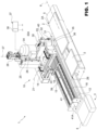
- FIG. 1 denoted as a whole by reference numeral 1 is a machine for grinding a glass sheet 2.
- the machine 1 is a bilateral machine, of the kind known in the prior art, comprising a base 3 with two lateral shoulders 4, only one of which is visible in the accompanying figures, and a conveyor 5, also of the kind known in the prior art, arranged between the shoulders 4 to feed the sheet 2 to be ground in a longitudinal and rectilinear direction 6 at a predefined speed.
- a corner grinding and polishing assembly denoted as a whole by reference numeral 10, is attached to or integral with the base 3.
- the assembly 10 which, in the example described, is an assembly for grinding and polishing the corners at the front 2A and at the rear 2B of the sheet 2, preferably, but not necessarily, while the sheet 2 is being moved along the direction 6, comprises an attachment frame 12, which is permanently connected to the respective shoulder 5 or coupled to said respective shoulder 4 in a releasable manner.
- the assembly 10 further comprises two configurable electro-pneumatic movement devices, a lower one, denoted by reference numeral 13 and an upper one, denoted by reference numeral 14.
- the lower device 13 comprises a lower guide and slide assembly 15 ( Fig. 2 ) which, in turn, comprises a rectilinear guide 16 permanently connected to the frame 12 and extending parallel to the longitudinal direction 6 and a slide 18.
- the slide 18 is coupled to the guide 16 so as to be able to slide in a direction parallel to the longitudinal direction 6.
- Integrally connected to and carried by the slide 18 is a rectilinear guide 19 of an upper assembly 20 for guiding and sliding the upper device 14.
- the guide 19 extends in a rectilinear transverse direction 21 orthogonal to the longitudinal direction 6 and to the slide 16 and carries coupled thereto a slide 22 able to move in opposite directions along said transverse direction 21.
- a vertical rectilinear guide 25 is permanently connected to the slide 22, extends upwards and carries, slidingly coupled thereto, a slide 26, able to move in opposite directions from and towards the slide 22 in a direction 27 orthogonal to the directions 6 and 21 driven by a motor 28 integral with the guide 25.
- an arm 30 is permanently connected, in a known manner, to the slide 26 and extends in a cantilevered manner from the slide 26 and carries, coupled to a free end portion, a grinding head 31.
- the grinding head 31 comprises a support 32 permanently connected to the arm 30, a vertical wheel shaft 33, which is rotatably coupled to the support 32 in a vertically fixed position and is able to rotate about its vertical axis 33A driven by a motor 34 coupled to the shaft 33 directly or by means of a known transmission, as in the example that is illustrated.
- a grinding wheel 35 and a polishing wheel 36 arranged on top of the grinding wheel 35 are fitted to a lower end section of the shaft 33 in a known manner.
- the motor 34 is electrically connected to a numerical control unit 37, of a type known in the prior art and not described in detail, which is part of the assembly 10 and also controls the motor 28.
- the unit 37 comprises a selection block 38 for selecting one or the other of the wheels 35,36 depending on the machining process to be performed on the sheet 2.
- the slides 18 and 22 are moved in opposite directions along the respective guides 16, 19 by respective configurable electro-pneumatic drive devices, denoted by reference numerals 39 and 40, respectively, both controlled by the unit 37.
- the device 39 comprises a drive screw 41 housed inside the guide 16 parallel to the direction 6 and rotatably coupled to said guide 16 in an axially fixed position by means of a pair of end bearings.
- the screw 41 is turned in opposite directions by a geared motor 42 of a type known in the prior art, having an electric motor 43 controlled by the numerical control unit 37.
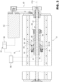
- a nut-screw 45 carrying, integrally connected to an axial end thereof, a tubular sleeve 46 surrounding the screw 41 with radial clearance ( Figure 3 ).
- An end section of the sleeve 46 defines the rod 47 of a double-acting pneumatic cylinder 48, which is part of the device 39 and extends coaxially with the axis 41A of the screw 41.
- the pneumatic cylinder 48 comprises a liner 49, which is permanently connected to the slide 22 by means of screws, surrounds the rod 47 and has two opposite end sections, denoted by reference numerals 50 and 51, which are coupled to an outer side surface of said rod 47 in a fluid-tight manner so as to delimit with said rod an airtight chamber 52.
- the chamber houses a plunger 53, which surrounds the rod 47 and is permanently connected to said rod 47. Conveniently, the plunger 53 is formed as one piece with the rod 47.
- the plunger 53 divides the chamber 52 into two variable-volume airtight chambers, denoted by reference numerals 54 ( Figure 3 ) and 55 ( Figure 4 ).
- the chambers 54 and 55 are both connected by means of ducts to a pneumatic valve assembly 56 of the type with proportional valves and controlled by the unit 44 to selectively pressurise the chambers 54 and 55 in a continuously controlled manner.
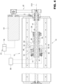
- the device 14 is structurally and functionally identical to the device 13 and its component parts are denoted by the same reference numerals as the corresponding parts of the device 13 with the addition of the subscript "′" to distinguish them from the corresponding parts of said device 13.
- the unit 37 and the pneumatic valve assembly 56 are common to the devices 39 and 40.
- the assembly 1 is therefore configured as a conventional grinding assembly driven by electric motors numerically controlled by the unit 37.
- the block 38 selects the polishing wheel 36 to polish the surfaces that have been ground by the grinding wheel 35
- the motors 43,43' continue to displace the shaft 31 and the wheel 35 along a path identical or parallel to the grinding path
- the chambers 55,55' are depressurised and the chambers 54,54' are pressurised, as illustrated in Figures 4 and 6 .
- a pneumatic spring is created between the plungers 53,53' and the sections 51,51', the stiffness or elasticity of which, depending on the path along which the wheel 36 is moved, is kept constant or changed in a controlled and continuous manner by adjusting the air pressure in the chambers 54,54'.
- the pressure in each of the chambers 54,54' can be changed by changing the output pressure from the block 56.
- the variation in pressure in the chamber 54 can be achieved according to a principle of variation equal to or different from that of the chamber 54'. In such conditions, during polishing, the wheel 36 is pushed against the sheet 2, applying, along each of the directions 6 and 21, a respective predefined and constant force as the wear on the wheel 36 changes.
- the air pressure in the chambers 54 and 54' is first brought to a predetermined constant value by the block 56, and, if necessary, it is adjusted by means of the motors 43,43' during the advancement of the wheel 36, that is, by modifying the instantaneous position of one or both of the plungers 53,53' in relation to a reference position, for example, the grinding position, and thus varying the volume of the chambers 54,54'.
- the liners 49,49' of the pneumatic actuators 48,48' could be permanently connected to the respective nut screws 45,45' and the plungers 53,53' could be permanently connected to the corresponding slides 18 and 22 or in any case act directly or indirectly on the arm 30.
- the pneumatic actuators could be arranged parallel to but in an eccentric position with respect to said directions 9 and 21.
- the possibility of having a pressurised air chamber interposed along each of the directions between the corresponding electric motor, and of using said chamber as a pneumatic pressure spring to push the polishing wheel 36 means that any of the ground surfaces on the sheet can be polished with the polishing wheel 36 always in the condition called for in the project while therefore constantly maintaining a high production output and the required surface quality. In such conditions, the pushing force is not controlled by the electric motor but by the pneumatic springs.
- the assembly 10 described herein is an independent grinding and finishing unit, not only is it suitable for use on bilateral machines other than the one described herein, but also on other non-bilateral grinding machines, such as rectilinear machines or machining centres. In the case of rectilinear machines, the assembly must clearly be turned so that the transverse direction is arranged vertically.
Landscapes
- Engineering & Computer Science (AREA)
- Mechanical Engineering (AREA)
- Chemical & Material Sciences (AREA)
- Ceramic Engineering (AREA)
- Inorganic Chemistry (AREA)
- Grinding And Polishing Of Tertiary Curved Surfaces And Surfaces With Complex Shapes (AREA)
- Polishing Bodies And Polishing Tools (AREA)
Description
- The present invention relates to an assembly for grinding and polishing a corner of a glass sheet.
- As is known, after grinding and polishing the perimeter surfaces of a glass sheet, machining of the sharp edges, that is to say, the corners where the polished perimeter surfaces come together, is often required.
- Machining of the sharp edges normally comprises, for each sharp edge, a grinding step consisting in a chamfering or rounding of said corner and, very often, a subsequent step of polishing the previously ground corner.
- The use of grinding and polishing assemblies for the rounding and subsequent polishing of such corners is known in the prior art, in which first a grinding wheel and then a polishing wheel are gradually moved along a predefined path according to the required geometry of the ground corner.
- In most applications, the displacement of each wheel along said path is obtained by combining two rectilinear movements along two mutually orthogonal directions. The displacement of the wheels along each of the directions and in relation to the sheet to be machined is obtained by means of a respective electric motor, independent of the other electric motor and controlled together with the other electric motor by a numerical control system common to the two motors.
- Though widely used, the assemblies of the type described above known in the prior art are difficult to control especially due to the fact that they must be controlled differently depending on whether the grinding wheel or the polishing wheel is used. In detail, the position of the grinding wheel must be strictly controlled since it removes material to define the geometry of the ground corner. The polishing wheel must, instead, be pushed and pressed against the profile that has been ground by the grinding wheel for the sole purpose of polishing the ground corner.
- If the pushing force applied to the polishing wheel is insufficient, this may, in some cases, result in unpolished corners and, in other cases, corners with different levels of polish. In both cases, the constant quality of the machined sheets cannot be guaranteed and it is often necessary to reject some of them, which clearly causes production problems and affects costs.
- Pressing the polishing wheel against the sheet with too much force might not adversely affect polishing of the corners, for a certain period at least, but certainly causes rapid wear on the polishing wheel with a consequent increase in tool costs and in the costs of replacing the wheel and loss of production owing to essential machine downtime.
- Moreover, on the one hand, timely detection of excessive wear on the polishing wheel is not easy since this is not part of any statistical analysis of wheel wear and, on the other, traditional indicators, such as changes in the current absorbed by the respective motor or changes in the torque requested of that motor, are not meaningful, since the polishing wheel remains in contact with the sheet for a very short time and the shorter the path along which the polishing wheel is displaced, the shorter this time. In such conditions, any change in the torque of the respective motor could even be disguised by the moment of inertia of the rotating parts. The polishing wheel often becomes worn so quickly that it is only noticed when several corners have polish defects, but at that point the polishing wheel already needs replacing.
- An assembly for grinding and polishing glass sheets is described, for example, in
CN 105 382 656 B , forming the basis for the preamble of claim 1, inEP 0 689 899 A1EP 2 246 152 A1 - The purpose of the present invention is to provide an assembly for grinding and polishing a corner of a glass sheet, which overcomes the problems described above in a simple and cost-effective manner and, in particular, makes it possible to maintain the quality of the machined product and, at the same time, to extend the service life of the wheels used for as long as possible.
- According to the present invention there is provided an assembly for grinding and polishing a corner of a glass sheet, as claimed in Claim 1.
- A further purpose of the present invention is to provide a method for grinding and polishing a corner of a glass sheet.
- According to the present invention there is provided a method for grinding and polishing a corner of a glass sheet, as claimed in
Claim 14. - The invention will now be described with reference to the accompanying drawings, illustrating a preferred embodiment thereof, in which:
-
Figure 1 is a schematic and substantially block diagram view of a machine for grinding glass sheets provided with an assembly for grinding and polishing corners produced according to the teachings of the present invention; -
Figure 2 is an exploded perspective view of the assembly for grinding and polishing corners inFigure 1 ; -
Figure 3 is a cross-sectional view on an enlarged scale along the line III-III ofFigure 2 ; -
Figure 4 is a cross-sectional view of a part of the assembly for grinding and polishing inFigure 3 arranged in a different functional configuration; -
Figure 5 is a cross-sectional view along the line V-V ofFigure 1 ; and -
Figure 6 is a cross-sectional view of a part of the assembly for grinding and polishing inFigure 5 arranged in a different functional configuration. - In
Figure 1 , denoted as a whole by reference numeral 1 is a machine for grinding aglass sheet 2. In the example that is illustrated, the machine 1 is a bilateral machine, of the kind known in the prior art, comprising a base 3 with twolateral shoulders 4, only one of which is visible in the accompanying figures, and aconveyor 5, also of the kind known in the prior art, arranged between theshoulders 4 to feed thesheet 2 to be ground in a longitudinal and rectilinear direction 6 at a predefined speed. - On the machine 1, for each
shoulder 4, a corner grinding and polishing assembly, denoted as a whole byreference numeral 10, is attached to or integral with the base 3. - Again with reference to
Figure 1 and, in particular, toFigure 2 , theassembly 10, which, in the example described, is an assembly for grinding and polishing the corners at thefront 2A and at the rear 2B of thesheet 2, preferably, but not necessarily, while thesheet 2 is being moved along the direction 6, comprises anattachment frame 12, which is permanently connected to therespective shoulder 5 or coupled to saidrespective shoulder 4 in a releasable manner. - The
assembly 10 further comprises two configurable electro-pneumatic movement devices, a lower one, denoted byreference numeral 13 and an upper one, denoted byreference numeral 14. - The
lower device 13 comprises a lower guide and slide assembly 15 (Fig. 2 ) which, in turn, comprises arectilinear guide 16 permanently connected to theframe 12 and extending parallel to the longitudinal direction 6 and aslide 18. Theslide 18 is coupled to theguide 16 so as to be able to slide in a direction parallel to the longitudinal direction 6. Integrally connected to and carried by theslide 18 is arectilinear guide 19 of an upper assembly 20 for guiding and sliding theupper device 14. Theguide 19 extends in a rectilineartransverse direction 21 orthogonal to the longitudinal direction 6 and to theslide 16 and carries coupled thereto aslide 22 able to move in opposite directions along saidtransverse direction 21. - The lower end of a vertical
rectilinear guide 25 is permanently connected to theslide 22, extends upwards and carries, slidingly coupled thereto, aslide 26, able to move in opposite directions from and towards theslide 22 in adirection 27 orthogonal to thedirections 6 and 21 driven by amotor 28 integral with theguide 25. - The end of an
arm 30 is permanently connected, in a known manner, to theslide 26 and extends in a cantilevered manner from theslide 26 and carries, coupled to a free end portion, agrinding head 31. - The grinding
head 31 comprises asupport 32 permanently connected to thearm 30, avertical wheel shaft 33, which is rotatably coupled to thesupport 32 in a vertically fixed position and is able to rotate about itsvertical axis 33A driven by amotor 34 coupled to theshaft 33 directly or by means of a known transmission, as in the example that is illustrated. - A grinding
wheel 35 and apolishing wheel 36 arranged on top of the grindingwheel 35 are fitted to a lower end section of theshaft 33 in a known manner. Themotor 34 is electrically connected to anumerical control unit 37, of a type known in the prior art and not described in detail, which is part of theassembly 10 and also controls themotor 28. Theunit 37 comprises aselection block 38 for selecting one or the other of thewheels sheet 2. - Again with reference to
Figure 2 and, in particular toFigures 3 and5 , theslides respective guides reference numerals unit 37. - The
device 39 comprises adrive screw 41 housed inside theguide 16 parallel to the direction 6 and rotatably coupled to saidguide 16 in an axially fixed position by means of a pair of end bearings. Thescrew 41 is turned in opposite directions by a gearedmotor 42 of a type known in the prior art, having anelectric motor 43 controlled by thenumerical control unit 37. - With reference to
Figure 3 , coupled to thescrew 41 is a nut-screw 45 carrying, integrally connected to an axial end thereof, atubular sleeve 46 surrounding thescrew 41 with radial clearance (Figure 3 ). - An end section of the
sleeve 46 defines therod 47 of a double-actingpneumatic cylinder 48, which is part of thedevice 39 and extends coaxially with theaxis 41A of thescrew 41. Thepneumatic cylinder 48, in turn, comprises aliner 49, which is permanently connected to theslide 22 by means of screws, surrounds therod 47 and has two opposite end sections, denoted byreference numerals rod 47 in a fluid-tight manner so as to delimit with said rod an airtight chamber 52. The chamber houses aplunger 53, which surrounds therod 47 and is permanently connected to saidrod 47. Conveniently, theplunger 53 is formed as one piece with therod 47. Theplunger 53 divides the chamber 52 into two variable-volume airtight chambers, denoted by reference numerals 54 (Figure 3 ) and 55 (Figure 4 ). Thechambers pneumatic valve assembly 56 of the type with proportional valves and controlled by the unit 44 to selectively pressurise thechambers - Again with reference to
Figures 5 and6 , thedevice 14 is structurally and functionally identical to thedevice 13 and its component parts are denoted by the same reference numerals as the corresponding parts of thedevice 13 with the addition of the subscript "′" to distinguish them from the corresponding parts ofsaid device 13. Theunit 37 and thepneumatic valve assembly 56 are common to thedevices - The method of operation of the
assembly 10 will now be described starting from a grinding configuration, illustrated inFigures 3 and5 , in which theblock 38 has selected thegrinding wheel 35 bringing it into a lowered grinding position, and thedevices wheel 35, for example to machine acorner 2A. In this configuration, thechambers 54,54' of thecylinders 48,48' are depressurised, whereas thechambers 55,55' are pressurised by theblock 56. Once thechambers 55,55' have been pressurised, therespective end sections 51,51' of thecorresponding liners 49,49' have respective axial shoulders that are practically in abutment against thecorresponding plungers 53,53', thus achieving a rigid coupling between thesleeves 47,47' and said liners. Thus, during the grinding process, the assembly 1 is therefore configured as a conventional grinding assembly driven by electric motors numerically controlled by theunit 37. - When, instead, the
block 38 selects thepolishing wheel 36 to polish the surfaces that have been ground by thegrinding wheel 35, themotors shaft 31 and thewheel 35 along a path identical or parallel to the grinding path, thechambers 55,55' are depressurised and thechambers 54,54' are pressurised, as illustrated inFigures 4 and6 . In these conditions, a pneumatic spring is created between theplungers 53,53' and thesections 51,51', the stiffness or elasticity of which, depending on the path along which thewheel 36 is moved, is kept constant or changed in a controlled and continuous manner by adjusting the air pressure in thechambers 54,54'. - The pressure in each of the
chambers 54,54' can be changed by changing the output pressure from theblock 56. The variation in pressure in thechamber 54 can be achieved according to a principle of variation equal to or different from that of the chamber 54'. In such conditions, during polishing, thewheel 36 is pushed against thesheet 2, applying, along each of thedirections 6 and 21, a respective predefined and constant force as the wear on thewheel 36 changes. - Alternatively, the air pressure in the
chambers 54 and 54' is first brought to a predetermined constant value by theblock 56, and, if necessary, it is adjusted by means of themotors wheel 36, that is, by modifying the instantaneous position of one or both of theplungers 53,53' in relation to a reference position, for example, the grinding position, and thus varying the volume of thechambers 54,54'. - The same considerations apply for machining the
rear corners 2B, except that the pressurisation of thechambers chamber 54 is pressurised and thechamber 55 is depressurised so that thesection 50 of theliner 49 is brought to cooperate directly in abutment against theplunger 53. - From the above it is apparent that modifications and variations may be made to the
assembly 10 described herein without departing from the scope of the independent claims. - For example, the
liners 49,49' of thepneumatic actuators 48,48' could be permanently connected to the respective nut screws 45,45' and theplungers 53,53' could be permanently connected to the corresponding slides 18 and 22 or in any case act directly or indirectly on thearm 30. - Moreover, instead of extending along the
directions 9 and 21, the pneumatic actuators could be arranged parallel to but in an eccentric position with respect to saiddirections 9 and 21. - Regardless of how the pneumatic actuators are arranged, the possibility of having a pressurised air chamber interposed along each of the directions between the corresponding electric motor, and of using said chamber as a pneumatic pressure spring to push the
polishing wheel 36 means that any of the ground surfaces on the sheet can be polished with thepolishing wheel 36 always in the condition called for in the project while therefore constantly maintaining a high production output and the required surface quality. In such conditions, the pushing force is not controlled by the electric motor but by the pneumatic springs. - From the above it is apparent that since the
assembly 10 described herein is an independent grinding and finishing unit, not only is it suitable for use on bilateral machines other than the one described herein, but also on other non-bilateral grinding machines, such as rectilinear machines or machining centres. In the case of rectilinear machines, the assembly must clearly be turned so that the transverse direction is arranged vertically. - Furthermore, from the above it is clear that only one of the
devices
Claims (18)
- An assembly (10) for grinding and polishing a corner (2A) (2B) of a glass sheet (2), the assembly comprising: a grinding wheel (35) and a polishing wheel (36), which can be selectively activated and are carried by the same motor-driven drive shaft (33); a first (13) and a second movement device (14) for displacing the motor-driven shaft (33) along a first rectilinear direction (41A) and a second rectilinear direction (21), respectively, which are transverse with respect to each other; each movement device (13)(14) comprising a corresponding rectilinear guide (16)(19), a corresponding slide (18) (22), slidably coupled to said guide (16)(19), a corresponding first mobile drive member (47) (47') for movement of the corresponding said slide (18) (22), and an electric motor (43) (43') for driving said first mobile drive member (47) (47'); the assembly (10) further comprising an electronic numerical control unit (37) for controlling each of said electric motors (43) (43'), and being characterised in that at least one of the movement devices (13)(14) is a configurable electro-pneumatic device and further comprises a pneumatic actuator (39)(40) having at least one first variable-volume air chamber (54) (54') and means (56) for pressurising said first variable-volume air chamber (54) (54') and for pushing the polishing wheel (36) against the sheet (2); said pneumatic actuator (39) (40) comprising a second mobile member (51) (51'), which partially delimits said first variable-volume chamber (54)(54') and is connected to the corresponding said slide; and in that it comprises configuration means (55,56)(55',56') that can be activated for connecting the first (47) (47') and the second mobile drive members (51) (51') rigidly together or by interposition of said first air chamber (54)(54').
- The assembly according to Claim 1, characterised in that both of the movement devices (13) (14) are configurable electro-pneumatic devices.
- The assembly according to Claim 1 or 2, characterised in that said electronic control unit (37) comprises selection means (38) for selecting one of said grinding and finishing wheels (35)(36) and control means for controlling said configuration means (55,56) as a function of the grinding wheel selected.
- The assembly according to any one of the preceding claims, characterised in that said configuration means comprise pneumatic means.
- The assembly according to Claim 4, characterised in that said configuration means comprise a second variable-volume air chamber (55)(55') that can be pressurised by means of further pressurisation means (56) .
- The assembly according to any one of the preceding claims, characterised in that, when said first and second mobile drive members (47) (47') (51) (51') are directly connected to one another, they have respective shoulders that are brought and kept in abutment against each other by said configuration means.
- The assembly according to Claim 6, characterised in that said shoulders partially delimit said first variable-volume air chamber (54)(54').
- The assembly according to any one of the preceding claims, characterised in that said first variable-volume air chamber (54) (54') extends parallel to a corresponding said rectilinear direction (41A) (21) .
- The assembly according to any one of the preceding claims, characterised in that said first variable-volume chamber(54) (54') extends coaxially with a corresponding said rectilinear direction (41A) (21) .
- The assembly according to any one of the preceding claims, characterised in that each said pneumatic actuator is a double-acting pneumatic actuator; said double-acting pneumatic actuator having a liner and a fluid-tight plunger that slides in said liner and delimiting said first variable-volume chamber (54)(54') and said second variable-volume chamber (55) (55'); one between said liner and said plunger being permanently connected to the corresponding said slide, and the other being permanently connected to the corresponding said first mobile drive member.
- The assembly according to Claim 10, characterised in that said plunger is permanently connected to said first mobile drive member.
- The assembly according to any one of the preceding claims, characterised in that each said movement device (13) (14) further comprises a nut-screw assembly (, which in turn comprises a screw, which extends along the corresponding said rectilinear direction and is rotatably coupled to the corresponding said guide in an axially fixed position, and a screw, which is angularly fixed with respect to the corresponding said guide and is permanently connected to the corresponding said first mobile drive member; said first mobile drive member being tubular and said screw traversing said first mobile drive member and being turned by a corresponding electric motor.
- The assembly according to Claim 10, characterised in that said plunger is permanently connected to the corresponding said slide, and the liner is permanently connected to said first mobile drive member.
- A method for grinding and polishing a corner (2A, 2B) of a glass sheet (2), the method being implemented using a grinding and polishing assembly (10) as per any one of the preceding claims and comprising a step of grinding the glass sheet (2) and a subsequent step of polishing the ground surface; wherein said grinding step is carried out by selecting the grinding wheel (35) and displacing said motor-driven shaft (33) by means of electric motors (43,43'), and in that said polishing step is carried out by selecting the polishing wheel (36) and using at least one pneumatic actuator (39, 40) for pushing the polishing wheel (36) against said ground sheet.
- The method according to Claim 14, characterised in that said polishing step is carried out by activating configuration means (55, 56; 55'; 56') so as to set, in at least one of said directions, a first variable-volume air chamber (54, 54') of a corresponding said pneumatic actuator (39, 40) between a first mobile drive member (47, 47') driven by the corresponding said electric motor (43, 43') and a second mobile drive member (51, 51') driven by the corresponding said pneumatic actuator (39, 40) and pressurising said first variable-volume air chamber (54, 54') so as to push the polishing wheel (36) by means of the corresponding second mobile drive member (51, 51').
- The method according to Claim 15, characterised in that said grinding step is carried out after rigidly connecting together the first mobile drive member (47, 47') and the corresponding said second mobile drive member (51, 51').
- The method according to Claim 16, characterised in that the permanent connection of said first mobile drive member (47, 47') to the corresponding said second mobile drive member (51, 51') is obtained by depressurising the corresponding said first variable-volume air chamber (54, 54') and pressurising a corresponding second variable-volume air chamber (55, 55') of the corresponding said pneumatic actuator (39, 40).
- The method according to any one of Claims 15 to 17, characterised in that the pushing force on said polishing wheel (36) is applied by varying the pressure in said first variable-volume air chamber (54, 54').
Applications Claiming Priority (1)
| Application Number | Priority Date | Filing Date | Title |
|---|---|---|---|
| IT102019000002925A IT201900002925A1 (en) | 2019-02-28 | 2019-02-28 | METHOD AND GROUP FOR GRINDING AND POLISHING AN EDGE OF A GLASS SHEET |
Publications (2)
| Publication Number | Publication Date |
|---|---|
| EP3702103A1 EP3702103A1 (en) | 2020-09-02 |
| EP3702103B1 true EP3702103B1 (en) | 2023-03-29 |
Family
ID=66641340
Family Applications (1)
| Application Number | Title | Priority Date | Filing Date |
|---|---|---|---|
| EP20159921.4A Active EP3702103B1 (en) | 2019-02-28 | 2020-02-27 | Method and assembly for grinding and polishing a corner of a glass sheet |
Country Status (3)
| Country | Link |
|---|---|
| EP (1) | EP3702103B1 (en) |
| ES (1) | ES2942911T3 (en) |
| IT (1) | IT201900002925A1 (en) |
Families Citing this family (4)
| Publication number | Priority date | Publication date | Assignee | Title |
|---|---|---|---|---|
| CN112388428B (en) * | 2020-10-04 | 2022-09-16 | 嘉兴优佳金属制品有限公司 | Stainless steel plate burr treatment device |
| CN113579976A (en) * | 2021-09-29 | 2021-11-02 | 佛山远钧智慧科技有限公司 | Grinding and polishing integrated machine tool |
| CN113977390B (en) * | 2021-11-24 | 2024-11-15 | 慈溪市海量玻璃技术有限公司 | Glass chamfering device |
| CN114536176A (en) * | 2022-03-29 | 2022-05-27 | 武汉江丰电子材料有限公司 | Target R-angle semi-automatic polishing system device, polishing method and application |
Family Cites Families (3)
| Publication number | Priority date | Publication date | Assignee | Title |
|---|---|---|---|---|
| IT1266734B1 (en) * | 1994-06-28 | 1997-01-14 | F M F Ind S R L | GROUP FOR THE GRINDING OF GLASS SHEETS. |
| IT1393877B1 (en) * | 2009-04-29 | 2012-05-11 | Bottero Spa | ROMPISPIGOLO GROUP FOR THE SMUSSO OF SPIDES OF GLASS SLABS |
| CN105382656B (en) * | 2015-12-11 | 2017-12-01 | 佛山山夏自动化机械有限公司 | Line glass automatic chamfering machine and chamfering method |
-
2019
- 2019-02-28 IT IT102019000002925A patent/IT201900002925A1/en unknown
-
2020
- 2020-02-27 ES ES20159921T patent/ES2942911T3/en active Active
- 2020-02-27 EP EP20159921.4A patent/EP3702103B1/en active Active
Also Published As
| Publication number | Publication date |
|---|---|
| ES2942911T3 (en) | 2023-06-07 |
| EP3702103A1 (en) | 2020-09-02 |
| IT201900002925A1 (en) | 2020-08-28 |
Similar Documents
| Publication | Publication Date | Title |
|---|---|---|
| EP3702103A1 (en) | Method and assembly for grinding and polishing a corner of a glass sheet | |
| US9289877B2 (en) | Device for the fine machining of optically active surfaces on, in particular, spectacle lenses | |
| CN104759962B (en) | A kind of novel numerical control profile glass edge grinding machine | |
| US7189143B2 (en) | Machine for superfinishing by honing | |
| KR101583563B1 (en) | Honing processing method and honing machine | |
| US6419443B2 (en) | Glass product machining apparatus | |
| CA2491800C (en) | Method and apparatus for grinding a rotating roller with an elastic staedy | |
| CN102596463B (en) | Device For Machining The Narrow Surfaces Of Preferably Board-shaped Workpieces | |
| CN101585165A (en) | Grindstone contact sensing method and its device, and honing method and honing machine | |
| CN108818166B (en) | Knife sharpener | |
| CN105538052A (en) | Rotating cutting tool grinding and clamping device | |
| CN108161678A (en) | Numerical control compound grinding machine | |
| JP2010076032A (en) | Taper honing processing method and taper honing machine | |
| CN103465158A (en) | Efficient peripheral continuous polishing machine | |
| US2818687A (en) | Internal grinding machine | |
| EP3702102B1 (en) | Machine and unit for grinding and polishing a glass sheet | |
| EP3875219A1 (en) | Grinding or polishing unit of a sheet, in particular a glass sheet, and method for processing sheets using such unit | |
| CN103962895A (en) | Special large cutter grinder for bearing cutter | |
| CN115284107B (en) | Forging burr grinding device | |
| CN116352162B (en) | Pneumatic pressurizing scissors | |
| EP0472948B1 (en) | Toolhead for a sheet glass cutting machine | |
| CN111085925A (en) | A multi-station automatic polishing machine | |
| CN110977720B (en) | Grinding wheel grinding device | |
| EP1403021A2 (en) | An apparatus for regulating a relative positioning of components in rotary machines for decoration of ceramic tiles | |
| KR20180118339A (en) | cylindrical grinder for internal and external processing |
Legal Events
| Date | Code | Title | Description |
|---|---|---|---|
| PUAI | Public reference made under article 153(3) epc to a published international application that has entered the european phase |
Free format text: ORIGINAL CODE: 0009012 |
|
| STAA | Information on the status of an ep patent application or granted ep patent |
Free format text: STATUS: THE APPLICATION HAS BEEN PUBLISHED |
|
| AK | Designated contracting states |
Kind code of ref document: A1 Designated state(s): AL AT BE BG CH CY CZ DE DK EE ES FI FR GB GR HR HU IE IS IT LI LT LU LV MC MK MT NL NO PL PT RO RS SE SI SK SM TR |
|
| AX | Request for extension of the european patent |
Extension state: BA ME |
|
| STAA | Information on the status of an ep patent application or granted ep patent |
Free format text: STATUS: REQUEST FOR EXAMINATION WAS MADE |
|
| 17P | Request for examination filed |
Effective date: 20210216 |
|
| GRAP | Despatch of communication of intention to grant a patent |
Free format text: ORIGINAL CODE: EPIDOSNIGR1 |
|
| STAA | Information on the status of an ep patent application or granted ep patent |
Free format text: STATUS: GRANT OF PATENT IS INTENDED |
|
| INTG | Intention to grant announced |
Effective date: 20220921 |
|
| GRAS | Grant fee paid |
Free format text: ORIGINAL CODE: EPIDOSNIGR3 |
|
| GRAA | (expected) grant |
Free format text: ORIGINAL CODE: 0009210 |
|
| STAA | Information on the status of an ep patent application or granted ep patent |
Free format text: STATUS: THE PATENT HAS BEEN GRANTED |
|
| AK | Designated contracting states |
Kind code of ref document: B1 Designated state(s): AL AT BE BG CH CY CZ DE DK EE ES FI FR GB GR HR HU IE IS IT LI LT LU LV MC MK MT NL NO PL PT RO RS SE SI SK SM TR |
|
| REG | Reference to a national code |
Ref country code: CH Ref legal event code: EP |
|
| REG | Reference to a national code |
Ref country code: DE Ref legal event code: R096 Ref document number: 602020009131 Country of ref document: DE |
|
| REG | Reference to a national code |
Ref country code: AT Ref legal event code: REF Ref document number: 1556340 Country of ref document: AT Kind code of ref document: T Effective date: 20230415 |
|
| REG | Reference to a national code |
Ref country code: IE Ref legal event code: FG4D |
|
| REG | Reference to a national code |
Ref country code: ES Ref legal event code: FG2A Ref document number: 2942911 Country of ref document: ES Kind code of ref document: T3 Effective date: 20230607 |
|
| REG | Reference to a national code |
Ref country code: LT Ref legal event code: MG9D |
|
| PG25 | Lapsed in a contracting state [announced via postgrant information from national office to epo] |
Ref country code: RS Free format text: LAPSE BECAUSE OF FAILURE TO SUBMIT A TRANSLATION OF THE DESCRIPTION OR TO PAY THE FEE WITHIN THE PRESCRIBED TIME-LIMIT Effective date: 20230329 Ref country code: NO Free format text: LAPSE BECAUSE OF FAILURE TO SUBMIT A TRANSLATION OF THE DESCRIPTION OR TO PAY THE FEE WITHIN THE PRESCRIBED TIME-LIMIT Effective date: 20230629 Ref country code: LV Free format text: LAPSE BECAUSE OF FAILURE TO SUBMIT A TRANSLATION OF THE DESCRIPTION OR TO PAY THE FEE WITHIN THE PRESCRIBED TIME-LIMIT Effective date: 20230329 Ref country code: LT Free format text: LAPSE BECAUSE OF FAILURE TO SUBMIT A TRANSLATION OF THE DESCRIPTION OR TO PAY THE FEE WITHIN THE PRESCRIBED TIME-LIMIT Effective date: 20230329 Ref country code: HR Free format text: LAPSE BECAUSE OF FAILURE TO SUBMIT A TRANSLATION OF THE DESCRIPTION OR TO PAY THE FEE WITHIN THE PRESCRIBED TIME-LIMIT Effective date: 20230329 |
|
| REG | Reference to a national code |
Ref country code: NL Ref legal event code: MP Effective date: 20230329 |
|
| PG25 | Lapsed in a contracting state [announced via postgrant information from national office to epo] |
Ref country code: SE Free format text: LAPSE BECAUSE OF FAILURE TO SUBMIT A TRANSLATION OF THE DESCRIPTION OR TO PAY THE FEE WITHIN THE PRESCRIBED TIME-LIMIT Effective date: 20230329 Ref country code: NL Free format text: LAPSE BECAUSE OF FAILURE TO SUBMIT A TRANSLATION OF THE DESCRIPTION OR TO PAY THE FEE WITHIN THE PRESCRIBED TIME-LIMIT Effective date: 20230329 Ref country code: GR Free format text: LAPSE BECAUSE OF FAILURE TO SUBMIT A TRANSLATION OF THE DESCRIPTION OR TO PAY THE FEE WITHIN THE PRESCRIBED TIME-LIMIT Effective date: 20230630 Ref country code: FI Free format text: LAPSE BECAUSE OF FAILURE TO SUBMIT A TRANSLATION OF THE DESCRIPTION OR TO PAY THE FEE WITHIN THE PRESCRIBED TIME-LIMIT Effective date: 20230329 |
|
| PG25 | Lapsed in a contracting state [announced via postgrant information from national office to epo] |
Ref country code: SM Free format text: LAPSE BECAUSE OF FAILURE TO SUBMIT A TRANSLATION OF THE DESCRIPTION OR TO PAY THE FEE WITHIN THE PRESCRIBED TIME-LIMIT Effective date: 20230329 Ref country code: RO Free format text: LAPSE BECAUSE OF FAILURE TO SUBMIT A TRANSLATION OF THE DESCRIPTION OR TO PAY THE FEE WITHIN THE PRESCRIBED TIME-LIMIT Effective date: 20230329 Ref country code: PT Free format text: LAPSE BECAUSE OF FAILURE TO SUBMIT A TRANSLATION OF THE DESCRIPTION OR TO PAY THE FEE WITHIN THE PRESCRIBED TIME-LIMIT Effective date: 20230731 Ref country code: EE Free format text: LAPSE BECAUSE OF FAILURE TO SUBMIT A TRANSLATION OF THE DESCRIPTION OR TO PAY THE FEE WITHIN THE PRESCRIBED TIME-LIMIT Effective date: 20230329 |
|
| PG25 | Lapsed in a contracting state [announced via postgrant information from national office to epo] |
Ref country code: SK Free format text: LAPSE BECAUSE OF FAILURE TO SUBMIT A TRANSLATION OF THE DESCRIPTION OR TO PAY THE FEE WITHIN THE PRESCRIBED TIME-LIMIT Effective date: 20230329 Ref country code: PL Free format text: LAPSE BECAUSE OF FAILURE TO SUBMIT A TRANSLATION OF THE DESCRIPTION OR TO PAY THE FEE WITHIN THE PRESCRIBED TIME-LIMIT Effective date: 20230329 Ref country code: IS Free format text: LAPSE BECAUSE OF FAILURE TO SUBMIT A TRANSLATION OF THE DESCRIPTION OR TO PAY THE FEE WITHIN THE PRESCRIBED TIME-LIMIT Effective date: 20230729 |
|
| REG | Reference to a national code |
Ref country code: DE Ref legal event code: R097 Ref document number: 602020009131 Country of ref document: DE |
|
| REG | Reference to a national code |
Ref country code: AT Ref legal event code: UEP Ref document number: 1556340 Country of ref document: AT Kind code of ref document: T Effective date: 20230329 |
|
| PG25 | Lapsed in a contracting state [announced via postgrant information from national office to epo] |
Ref country code: DK Free format text: LAPSE BECAUSE OF FAILURE TO SUBMIT A TRANSLATION OF THE DESCRIPTION OR TO PAY THE FEE WITHIN THE PRESCRIBED TIME-LIMIT Effective date: 20230329 Ref country code: CZ Free format text: LAPSE BECAUSE OF FAILURE TO SUBMIT A TRANSLATION OF THE DESCRIPTION OR TO PAY THE FEE WITHIN THE PRESCRIBED TIME-LIMIT Effective date: 20230329 |
|
| PLBE | No opposition filed within time limit |
Free format text: ORIGINAL CODE: 0009261 |
|
| STAA | Information on the status of an ep patent application or granted ep patent |
Free format text: STATUS: NO OPPOSITION FILED WITHIN TIME LIMIT |
|
| 26N | No opposition filed |
Effective date: 20240103 |
|
| PG25 | Lapsed in a contracting state [announced via postgrant information from national office to epo] |
Ref country code: SI Free format text: LAPSE BECAUSE OF FAILURE TO SUBMIT A TRANSLATION OF THE DESCRIPTION OR TO PAY THE FEE WITHIN THE PRESCRIBED TIME-LIMIT Effective date: 20230329 |
|
| PG25 | Lapsed in a contracting state [announced via postgrant information from national office to epo] |
Ref country code: SI Free format text: LAPSE BECAUSE OF FAILURE TO SUBMIT A TRANSLATION OF THE DESCRIPTION OR TO PAY THE FEE WITHIN THE PRESCRIBED TIME-LIMIT Effective date: 20230329 Ref country code: IT Free format text: LAPSE BECAUSE OF FAILURE TO SUBMIT A TRANSLATION OF THE DESCRIPTION OR TO PAY THE FEE WITHIN THE PRESCRIBED TIME-LIMIT Effective date: 20230329 |
|
| PG25 | Lapsed in a contracting state [announced via postgrant information from national office to epo] |
Ref country code: MC Free format text: LAPSE BECAUSE OF FAILURE TO SUBMIT A TRANSLATION OF THE DESCRIPTION OR TO PAY THE FEE WITHIN THE PRESCRIBED TIME-LIMIT Effective date: 20230329 |
|
| PG25 | Lapsed in a contracting state [announced via postgrant information from national office to epo] |
Ref country code: LU Free format text: LAPSE BECAUSE OF NON-PAYMENT OF DUE FEES Effective date: 20240227 |
|
| GBPC | Gb: european patent ceased through non-payment of renewal fee |
Effective date: 20240227 |
|
| PG25 | Lapsed in a contracting state [announced via postgrant information from national office to epo] |
Ref country code: LU Free format text: LAPSE BECAUSE OF NON-PAYMENT OF DUE FEES Effective date: 20240227 |
|
| PG25 | Lapsed in a contracting state [announced via postgrant information from national office to epo] |
Ref country code: BG Free format text: LAPSE BECAUSE OF FAILURE TO SUBMIT A TRANSLATION OF THE DESCRIPTION OR TO PAY THE FEE WITHIN THE PRESCRIBED TIME-LIMIT Effective date: 20230329 |
|
| PG25 | Lapsed in a contracting state [announced via postgrant information from national office to epo] |
Ref country code: BG Free format text: LAPSE BECAUSE OF FAILURE TO SUBMIT A TRANSLATION OF THE DESCRIPTION OR TO PAY THE FEE WITHIN THE PRESCRIBED TIME-LIMIT Effective date: 20230329 |
|
| REG | Reference to a national code |
Ref country code: BE Ref legal event code: MM Effective date: 20240229 |
|
| PG25 | Lapsed in a contracting state [announced via postgrant information from national office to epo] |
Ref country code: BE Free format text: LAPSE BECAUSE OF NON-PAYMENT OF DUE FEES Effective date: 20240229 |
|
| PG25 | Lapsed in a contracting state [announced via postgrant information from national office to epo] |
Ref country code: GB Free format text: LAPSE BECAUSE OF NON-PAYMENT OF DUE FEES Effective date: 20240227 |
|
| PG25 | Lapsed in a contracting state [announced via postgrant information from national office to epo] |
Ref country code: IE Free format text: LAPSE BECAUSE OF NON-PAYMENT OF DUE FEES Effective date: 20240227 |
|
| PG25 | Lapsed in a contracting state [announced via postgrant information from national office to epo] |
Ref country code: IE Free format text: LAPSE BECAUSE OF NON-PAYMENT OF DUE FEES Effective date: 20240227 Ref country code: GB Free format text: LAPSE BECAUSE OF NON-PAYMENT OF DUE FEES Effective date: 20240227 Ref country code: BE Free format text: LAPSE BECAUSE OF NON-PAYMENT OF DUE FEES Effective date: 20240229 |
|
| PG25 | Lapsed in a contracting state [announced via postgrant information from national office to epo] |
Ref country code: CY Free format text: LAPSE BECAUSE OF FAILURE TO SUBMIT A TRANSLATION OF THE DESCRIPTION OR TO PAY THE FEE WITHIN THE PRESCRIBED TIME-LIMIT; INVALID AB INITIO Effective date: 20200227 |
|
| PG25 | Lapsed in a contracting state [announced via postgrant information from national office to epo] |
Ref country code: HU Free format text: LAPSE BECAUSE OF FAILURE TO SUBMIT A TRANSLATION OF THE DESCRIPTION OR TO PAY THE FEE WITHIN THE PRESCRIBED TIME-LIMIT; INVALID AB INITIO Effective date: 20200227 |
|
| PG25 | Lapsed in a contracting state [announced via postgrant information from national office to epo] |
Ref country code: TR Free format text: LAPSE BECAUSE OF FAILURE TO SUBMIT A TRANSLATION OF THE DESCRIPTION OR TO PAY THE FEE WITHIN THE PRESCRIBED TIME-LIMIT Effective date: 20230329 |
|
| REG | Reference to a national code |
Ref country code: CH Ref legal event code: U11 Free format text: ST27 STATUS EVENT CODE: U-0-0-U10-U11 (AS PROVIDED BY THE NATIONAL OFFICE) Effective date: 20260301 |
|
| PGFP | Annual fee paid to national office [announced via postgrant information from national office to epo] |
Ref country code: ES Payment date: 20260302 Year of fee payment: 7 |
|
| PGFP | Annual fee paid to national office [announced via postgrant information from national office to epo] |
Ref country code: DE Payment date: 20260121 Year of fee payment: 7 |
|
| PGFP | Annual fee paid to national office [announced via postgrant information from national office to epo] |
Ref country code: AT Payment date: 20260123 Year of fee payment: 7 |
|
| PGFP | Annual fee paid to national office [announced via postgrant information from national office to epo] |
Ref country code: FR Payment date: 20260121 Year of fee payment: 7 |
|
| PGFP | Annual fee paid to national office [announced via postgrant information from national office to epo] |
Ref country code: CH Payment date: 20260301 Year of fee payment: 7 |