EP3702017A1 - Crossflow filter device - Google Patents
Crossflow filter device Download PDFInfo
- Publication number
- EP3702017A1 EP3702017A1 EP19159491.0A EP19159491A EP3702017A1 EP 3702017 A1 EP3702017 A1 EP 3702017A1 EP 19159491 A EP19159491 A EP 19159491A EP 3702017 A1 EP3702017 A1 EP 3702017A1
- Authority
- EP
- European Patent Office
- Prior art keywords
- membrane
- retentate
- filter device
- filtrate
- flow channel
- Prior art date
- Legal status (The legal status is an assumption and is not a legal conclusion. Google has not performed a legal analysis and makes no representation as to the accuracy of the status listed.)
- Withdrawn
Links
- 239000012528 membrane Substances 0.000 claims abstract description 98
- 239000007788 liquid Substances 0.000 claims abstract description 61
- 239000012465 retentate Substances 0.000 claims abstract description 55
- 239000000706 filtrate Substances 0.000 claims abstract description 50
- 239000012530 fluid Substances 0.000 claims abstract description 10
- 238000001914 filtration Methods 0.000 claims abstract description 8
- 230000015572 biosynthetic process Effects 0.000 claims description 8
- 238000005755 formation reaction Methods 0.000 claims description 8
- 238000007789 sealing Methods 0.000 claims description 5
- 229920003023 plastic Polymers 0.000 description 9
- 239000004033 plastic Substances 0.000 description 8
- 239000000463 material Substances 0.000 description 6
- 238000003466 welding Methods 0.000 description 6
- 238000004519 manufacturing process Methods 0.000 description 5
- 229920001971 elastomer Polymers 0.000 description 4
- 239000000806 elastomer Substances 0.000 description 4
- 238000000034 method Methods 0.000 description 4
- 239000004433 Thermoplastic polyurethane Substances 0.000 description 3
- 238000000465 moulding Methods 0.000 description 3
- 244000043261 Hevea brasiliensis Species 0.000 description 2
- 230000005484 gravity Effects 0.000 description 2
- 238000005304 joining Methods 0.000 description 2
- 239000004816 latex Substances 0.000 description 2
- 229920000126 latex Polymers 0.000 description 2
- 229920003052 natural elastomer Polymers 0.000 description 2
- 229920001194 natural rubber Polymers 0.000 description 2
- -1 polysilaxane Substances 0.000 description 2
- 229920002379 silicone rubber Polymers 0.000 description 2
- 239000004945 silicone rubber Substances 0.000 description 2
- 238000005245 sintering Methods 0.000 description 2
- 238000005728 strengthening Methods 0.000 description 2
- 239000004695 Polyether sulfone Substances 0.000 description 1
- 238000004026 adhesive bonding Methods 0.000 description 1
- 229960000074 biopharmaceutical Drugs 0.000 description 1
- 229920002301 cellulose acetate Polymers 0.000 description 1
- 239000000919 ceramic Substances 0.000 description 1
- 239000012141 concentrate Substances 0.000 description 1
- 238000011109 contamination Methods 0.000 description 1
- 238000009295 crossflow filtration Methods 0.000 description 1
- 125000004122 cyclic group Chemical group 0.000 description 1
- 239000011521 glass Substances 0.000 description 1
- 238000002386 leaching Methods 0.000 description 1
- 239000002184 metal Substances 0.000 description 1
- 238000012986 modification Methods 0.000 description 1
- 230000004048 modification Effects 0.000 description 1
- 229920006393 polyether sulfone Polymers 0.000 description 1
- 239000004627 regenerated cellulose Substances 0.000 description 1
- 238000013341 scale-up Methods 0.000 description 1
- 238000004381 surface treatment Methods 0.000 description 1
- 239000012780 transparent material Substances 0.000 description 1
Images

Classifications
-
- B—PERFORMING OPERATIONS; TRANSPORTING
- B01—PHYSICAL OR CHEMICAL PROCESSES OR APPARATUS IN GENERAL
- B01D—SEPARATION
- B01D61/00—Processes of separation using semi-permeable membranes, e.g. dialysis, osmosis or ultrafiltration; Apparatus, accessories or auxiliary operations specially adapted therefor
- B01D61/14—Ultrafiltration; Microfiltration
- B01D61/145—Ultrafiltration
-
- B—PERFORMING OPERATIONS; TRANSPORTING
- B01—PHYSICAL OR CHEMICAL PROCESSES OR APPARATUS IN GENERAL
- B01D—SEPARATION
- B01D63/00—Apparatus in general for separation processes using semi-permeable membranes
- B01D63/08—Flat membrane modules
- B01D63/087—Single membrane modules
-
- B—PERFORMING OPERATIONS; TRANSPORTING
- B01—PHYSICAL OR CHEMICAL PROCESSES OR APPARATUS IN GENERAL
- B01D—SEPARATION
- B01D61/00—Processes of separation using semi-permeable membranes, e.g. dialysis, osmosis or ultrafiltration; Apparatus, accessories or auxiliary operations specially adapted therefor
- B01D61/14—Ultrafiltration; Microfiltration
- B01D61/18—Apparatus therefor
-
- B—PERFORMING OPERATIONS; TRANSPORTING
- B01—PHYSICAL OR CHEMICAL PROCESSES OR APPARATUS IN GENERAL
- B01D—SEPARATION
- B01D65/00—Accessories or auxiliary operations, in general, for separation processes or apparatus using semi-permeable membranes
- B01D65/003—Membrane bonding or sealing
-
- B—PERFORMING OPERATIONS; TRANSPORTING
- B01—PHYSICAL OR CHEMICAL PROCESSES OR APPARATUS IN GENERAL
- B01D—SEPARATION
- B01D2313/00—Details relating to membrane modules or apparatus
- B01D2313/04—Specific sealing means
- B01D2313/041—Gaskets or O-rings
-
- B—PERFORMING OPERATIONS; TRANSPORTING
- B01—PHYSICAL OR CHEMICAL PROCESSES OR APPARATUS IN GENERAL
- B01D—SEPARATION
- B01D2313/00—Details relating to membrane modules or apparatus
- B01D2313/08—Flow guidance means within the module or the apparatus
-
- B—PERFORMING OPERATIONS; TRANSPORTING
- B01—PHYSICAL OR CHEMICAL PROCESSES OR APPARATUS IN GENERAL
- B01D—SEPARATION
- B01D2313/00—Details relating to membrane modules or apparatus
- B01D2313/08—Flow guidance means within the module or the apparatus
- B01D2313/086—Meandering flow path over the membrane
-
- B—PERFORMING OPERATIONS; TRANSPORTING
- B01—PHYSICAL OR CHEMICAL PROCESSES OR APPARATUS IN GENERAL
- B01D—SEPARATION
- B01D2313/00—Details relating to membrane modules or apparatus
- B01D2313/14—Specific spacers
- B01D2313/143—Specific spacers on the feed side
-
- B—PERFORMING OPERATIONS; TRANSPORTING
- B01—PHYSICAL OR CHEMICAL PROCESSES OR APPARATUS IN GENERAL
- B01D—SEPARATION
- B01D2313/00—Details relating to membrane modules or apparatus
- B01D2313/54—Modularity of membrane module elements
-
- B—PERFORMING OPERATIONS; TRANSPORTING
- B01—PHYSICAL OR CHEMICAL PROCESSES OR APPARATUS IN GENERAL
- B01D—SEPARATION
- B01D2315/00—Details relating to the membrane module operation
- B01D2315/10—Cross-flow filtration
-
- B—PERFORMING OPERATIONS; TRANSPORTING
- B01—PHYSICAL OR CHEMICAL PROCESSES OR APPARATUS IN GENERAL
- B01D—SEPARATION
- B01D2315/00—Details relating to the membrane module operation
- B01D2315/16—Diafiltration
Definitions
- the present disclosure relates to the field of crossflow filter devices for filtering pressurised feed liquids.
- Crossflow filtration is a process in which a pressurised feed liquid is forced to flow tangentially over a membrane permeable to a filtrate derivable from the feed liquid. As the feed liquid flows over one side of the membrane, the filtrate passes through to the other side of the membrane, leaving behind a retentate liquid, which is the feed liquid depleted of filtrate. Media in the feed liquid that do not pass through the membrane are thus concentrated in the retentate liquid.
- the feed liquid flows in a cyclic manner into a crossflow filter device, over the membrane, and out again, with the media concentrating in the retentate liquid with each such cycle.
- the filtrate which has passed through the membrane exits the device through an outlet on the opposite side of the membrane.
- a flow restrictor at the retentate outlet is used to create pressure within the device.
- Vivaflow 200TM available from Sartorius.
- the Vivaflow 200TM is formed as a cassette which has rigid, clear plastic, retentate-side and filtrate-side plates. These plates are thick enough to resist the stresses produced by the pressure of throughflowing liquids and are bolted together around their perimeters.
- the cassette housing thus-formed sealingly contains a flow channel for the feed liquid / retentate liquid, a permeable membrane, and a plate-like, porous support body which supports the membrane while allowing relatively unimpeded passage therethrough of liquids, such as the filtrate.
- the cassette further features an inlet in the retentate-side plate for the feed liquid to the flow channel, an outlet in the retentate-side plate for the retentate liquid from the flow channel, and a further outlet in the filtrate-side plate for the filtrate which has passed through the membrane and the support body.
- the flow channel shuttles back and forth over the retentate surface of the membrane, which helps to expose all the feed liquid to a large surface area of the membrane, and also introduces a convoluted path to create eddies and break up linear flow of the feed liquid, thus improving the filtration efficiency of the cassette.
- the flow channel is formed as a recess in the inner surface of the retentate-side plate.
- the retentate-side plate, membrane, support body and filtrate-side plate are stacked in that order, and the retentate-side and filtrate-side plates are then bolted together.
- the raised parts of the inner surface of the retentate-side plate which are outside the recess press against the membrane, and the front-to-back depth of the flow channel is just the depth of the recess.
- the Vivaflow 50TM is a similar, but smaller, crossflow filter device, also available from Sartorius. It performs the same function as the Vivaflow 200TM but has some constructional differences. For example, its retentate-side and filtrate-side plates are wedged into a thick plastic sleeve to press them together, and are sealed to each other with a perimeter O-ring.
- a crossflow filter device for filtering a pressurised feed liquid
- the crossflow filter device comprises: a filter membrane; a flow channel for the pressurised feed liquid which extends in a path over a retentate surface of the membrane such that the direction of flow in the channel is tangential to the retentate surface, and a filtrate derived from the feed liquid passes through the membrane leaving retentate liquid in the flow channel; and a collection chamber for the filtrate formed on an opposite, filtrate surface of the membrane;
- the crossflow filter device further comprises a sealed housing having a retentate side and a filtrate side which enclose therebetween the flow channel, the filter membrane and the collection chamber; and wherein the crossflow filter device further comprises, flow channel guide walls provided at an inner surface of the retentate side of the housing, which guide walls are configured to form a fluid tight seal with the filter membrane and thereby define the path of the flow channel over the retentate surface of the membrane.
- the guide walls can provide effective sealing around the edges of the flow channel, and thereby substantially eliminate short-circuiting of the flow channel by the feed liquid.
- the crossflow filter device of the first aspect may have any one or any combination of the following optional features.
- the flow channel guide walls may be resiliently deformable. They can then deform and sealingly engage with the filter membrane to form the fluid tight seal.
- the guide walls can accommodate and seal to different types of membrane, such that different types of membrane can be used in the same basic device.
- the resiliently deformable flow channel guide walls may be formed of elastomer, such as thermoplastic poly-urethane (TPU), natural rubber, silicone rubber, polysilaxane, or latex.
- TPU thermoplastic poly-urethane
- the guide walls may have a single component structure, or a multicomponent structure, for example a multilayer structure having layers formed of different materials such as different ones of the aforementioned elastomers.
- the resiliently deformable guide walls may be a separate component of the device from the housing, and therefore should be correctly presented thereto on assembly of the device.
- the inner surface of the retentate side of the housing may include a recess corresponding to the line of the guide walls and in which the resiliently deformable guide walls locate to sealingly engage with that inner surface.
- the recess can help to correctly position the guide walls on assembly of the device. Particularly if the guide walls are a snug fit in the recess, it may also help to improve the seal between the guide walls and the inner surface of the retentate side of the housing.
- the resiliently deformable guide walls to be permanently co-moulded into the retentate side of the housing during manufacture of these parts of the device. In this way, the guide walls become integral to the housing, and any problems of sealing the guide walls to the retentate side of the housing are avoided.
- the crossflow filter device comprising the resiliently deformable guide walls may further comprise one or more interconnecting members which extend across the afore-mentioned cavity, preferably outside the path of the flow channel, to join the inner surface of the retentate side of the housing to an inner surface of the filtrate side of the housing and thereby strengthen the housing.
- the interconnecting members may penetrate through openings in the membrane and, in devices comprising a foraminous support body (discussed below), may also penetrate through openings in the support body.
- the interconnecting members can strengthen the housing against the pressure of the throughflowing liquid, and thus allow the thickness of the housing to be reduced. This in turn can help to reduce manufacturing costs.
- the interconnecting members may, for example, be integrally formed as projections from the inner surface of one of the retentate and filtrate sides of the housing. They may be joined to the inner surface of the other side using any convenient process, such as ultrasonic welding. Another option, however, is for the interconnecting members to be integrally formed as pairs of projections from the inner surfaces of respectively the retentate and filtrate sides of the housing, each pair of projections meeting at the membrane. In this case, there may be no need for the interconnecting members to penetrate through openings in the membrane, i.e. each interconnecting member can be formed by a given pair of projections and a small region of membrane trapped therebetween.
- the guide walls may be welded to the filter membrane, the weld locally densifying the filter membrane across its entire thickness to form the fluid tight seal.
- the weld can be formed by ultrasonic welding.
- this option also allows the guide walls to seal to different types of membrane, such that different types of membrane can again be used in the same basic device.
- the device may further comprise weld support members which extend from an inner surface of the filtrate side of the housing to support the welds.
- the weld support members may also be welded to the filter membrane.
- the welded guide walls and weld support members, as well as forming the fluid tight seal, can also help to strengthen the housing in the manner of the interconnecting members discussed above.
- the weld support members may penetrate through openings in the support body.
- the guide walls can be integrally formed with the retentate side of the housing and/or the weld support members can be integrally formed with the filtrate side of the housing.
- the guide walls may be configured such that the path for the flow channel shuttles back and forth over the retentate surface of the membrane. This improves filtration efficiency by forcing all the feed liquid to pass over a large area of the membrane, and helps to create eddies and turbulence to break up linear flow.
- the device may further comprise: an inlet to the flow channel for the feed liquid; an outlet from the flow channel for the retentate liquid; and an outlet from the collection chamber for the filtrate.
- external tubes are typically attached to the device at the inlet and outlets, for example such that an external pump can cycle the feed liquid and retentate liquid through the device.
- the inlet to the flow channel and the outlet from the flow channel may be formed in the retentate side of the housing, and the outlet from the collection chamber may be formed in the filtrate side of the housing.
- One or more of the inlet and the outlets may include a respective rotating Luer cuff for connection to respective external tubing.
- the device may further comprise a foraminous support body located within the collection chamber, the support body providing mechanical support to the membrane while allowing relatively unimpeded passage therethrough of the filtrate, e.g. to a filtrate outlet.
- the support body may be made, for example, of porous plastic. It may be manufactured by sintering plastic particulate. However, other materials and/or manufacturing processes can be used.
- protuberances integrally formed with the housing may project from an inner surface of the filtrate side of the housing to support the membrane, the protuberances allowing relatively unimpeded passage therebetween of the filtrate.
- the housing may be formed of transparent material. This allows the operation of the device to be visually monitored by a user. Conveniently, it can be formed of plastic material. However other types of material, such as glass, ceramic or metal may be used for the housing.
- the retentate side and filtrate side of the housing may be formed as respective plates which sandwich the flow channel guide walls, the filter membrane and the foraminous support body (if present) therebetween.
- the housing may have a retentate-side plate and a filtrate-side plate which are sealed together along respective sealing perimeters to form a cavity therebetween in which the guide walls, the filter membrane, and the foraminous support body (if present) are housed.
- An O-ring may be provided around the sealing perimeters to perfect the seal therebetween.
- the plates may be sealed together by various means, for example: ultrasonic welding, heat staking; gluing; or mechanical interference.
- the joining of the plates may be performed or supplemented by mechanical fasteners (e.g. screws, bolts, staples, clamps etc.), integral snap-fit connectors, and/or a wedge-fit mechanism.
- the sealed housing further includes a moulded or overmoulded surround which joins the casings together.
- the device may further comprise complimentary formations located on opposing sides of the device and configured such that a formation on one side of a device can engage with the complimentary formation on the other side of another device such that plural devices can be joined together in a larger grouping.
- the complimentary formations may include a pair of male and female formations such as a rail and a groove.
- the devices of such a larger grouping may be fluidly connected in parallel or in series to process larger volumes of feed liquid.
- the device may further comprise external support feet projecting from the filtrate side of the housing.
- the devices When the feet are placed on a work surface (e.g. laboratory bench), the device is thereby raised from the surface giving improved access to e.g. its inlet and the outlets and particularly any rotating Luer cuff.
- the collection chamber will be below the filter membrane such that gravity can assist the passage of filtrate through the membrane.
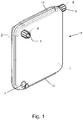
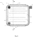
- Figure 1 shows a perspective view of a sealed housing of a crossflow filter device 17, the housing comprising a retentate-side plate 1 and a filtrate-side plate 2 which define a cavity therebetween.
- An inlet 7 for flow of a feed liquid into the cavity is formed in the retentate-side plate 1
- an outlet 8 for flow of a retentate liquid 8 out of the cavity is formed in the retentate-side plate 1
- an outlet 9 for a flow of filtrate out of the cavity is formed in the filtrate-side plate 2.
- the feed liquid inlet 7 has a female Luer connection, while the retentate liquid outlet 8 and the filtrate outlet 9 each has a male Luer connection with a respective rotating Luer cuff 6.
- the Luer connections allow external tubing connectors to be attached to the device 17.
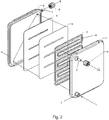
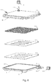
- Figures 2 to 4 are respective exploded views of the crossflow filter device 17 of Figure 1 .
- Figures 2 and 4 allow the inner surface of the filtrate-side plate 2 to be seen, while Figure 3 allows the inner surface of the retentate-side plate 1 to be seen.
- the housing plates 1, 2 are formed as respective square plates, and sandwich therebetween, in order from the retentate side to the filtrate side: resiliently deformable flow channel guide walls 3, a filter membrane 4, and a foraminous support body 5.
- the plates 1, 2 are joined together around their respective perimeters, as discussed in more detail below, to form a sealed module.
- the plates 1, 2 may be formed of rigid, transparent plastic material.
- the guide walls 3 are formed as a single piece elastomer moulding which, when engaged on one side with the inner surface of the retentate-side plate 1 and on the other side with the filter membrane 4, defines the path of a flow channel 10 which shuttles back and forth over the retentate surface of the membrane 4 from the inlet 7 to the outlet 8.
- the inner surface of the retentate-side plate 1 has a recess 18 formed therein (shown in Figure 3 ), corresponding to the line of the guide walls 3 and into which the walls can be fitted.
- the guide walls 3 can be co-moulded to the retentate-side plate 1 such that the two parts are permanently integrated.
- the guide walls 3 are made of a medically-safe elastomer, such as TPU, natural rubber, silicone rubber, polysilaxane, or latex, which is highly resistant to leaching. This lowers or avoids any risk of contamination of filtrates and feed liquids / retentates flowing through the device 17.
- the guide walls 3, being elastically compliant, adapt to and accommodate any irregularities in the retentate surface of the filter membrane 4, forming a good seal around the edges of the flow channel 10. They thus substantially prevent any short-circuiting of the flow channel 10 by liquid on the flow path 10 from the inlet 7 to the outlet 8.
- the same basic filter device can be used in many different applications, simply by changing the membrane type.
- the device 17 can be used to scale-up or scale-down laboratory bench filtration, e.g. for the production of biopharmaceuticals such as antibodies.
- the foraminous support body 5 fills a collection chamber for the filtrate created by that part of the housing cavity between the membrane 4 and the inner surface of the filtrate-side plate 2.
- the support body 5 physically supports the membrane 4 over substantially its entire area, allowing a pressure difference to be established across the membrane 4 that drives the flow of filtrate therethrough.
- the fora on the body 5 are formed such that filtrate can pass through it relatively unimpeded en route from the membrane 4 to the outlet 9 via the collection chamber.
- the body 5 can be a porous plastic body formed by sintering plastic particulate.
- external tubing attached to the feed liquid inlet 7 and the retentate liquid outlet 8 are joined to an external pump. Further external tubing attaches to the filtrate outlet 9 and extends to a collection vessel.
- the pump continuously circulates a feed liquid into the device via the inlet 7, along the flow channel 10 defined by the guide walls 3, and back to the pump as retentate liquid from the outlet 8.
- the direction of flow of the liquid in the flow channel 10 is tangential to the retentate surface of the membrane 4, and the pressure differential across the membrane 4 drives the flow of the filtrate derived from the feed liquid through the membrane 4.
- a flow restrictor (not shown) at the retentate outlet 9 is used to create the pressure within the device 17.
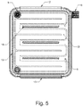
- the shuttling back and forth of the flow channel 10 forces all of the feed liquid to pass over a large surface area of the retentate surface of the membrane 4. It also creates eddies and turbulence in the feed liquid, which break up linear flow thereof. More specifically, the path of the flow channel 10 is comprised of a series of consecutive, anti-parallel linear runs that span a width of the membrane 4 and are connected by successive 180° degree turns.
- Figure 5 is a plan view of the crossflow filter device 17, with internal features indicated by dashed lines, and best shows the path of the flow channel 10.
- a result of operating the device is therefore that, as the pump circulates the feed liquid, filtrate derived from the feed liquid passes through the foraminous support body to collect in the collection vessel attached to the filtrate outlet 9, and media in the feed liquid that do not pass through the membrane 4 concentrate in the retentate liquid.
- the housing plates 1, 2 may be sealed together along a perimeter groove 14 of one of the plates (in this example the filtrate-side plate 2, as shown in Figures 2 and 4 ) and a corresponding perimeter ridge 15 of the other plate, (in this example the retentate-side plate 1, as shown in Figure 3 ).
- the ridge 15 fits into the groove 14 and acts as an energy director allowing the plates 1, 2 to be ultrasonically welded together around their perimeters.
- interconnecting members 16 may be provided to physically link the inner surfaces of the housing plates 1, 2.
- the interconnecting members 16 penetrate, outside the path of the flow channel 10, through dedicated openings in the membrane 4 and in the support body 5.
- the interconnecting members 16 can be formed as projections from the inner surface of one of the plates (in this example, the retentate-side plate 1), and on assembly of the device 17 can be joined to the inner surface of the other plate (in this example, the filtrate-side plate 2) by a suitable joining process.
- the interconnecting members 16 can act as further energy directors, allowing them to be ultrasonically welded to the other plate.
- the filtrate-side plate 2 has external feet 11 (shown in Figures 3 and 4 ) at each of its corners on which the device 17 can rest.
- the feet 11 When the feet 11 are placed on a work surface, the device 17 is supported such that the collection chamber lies directly below the membrane 4. This allows gravity to assist the flow of filtrate through the membrane 4.
- the feet 11 raise the level of the entire device so that the Luer cuff 6 for the outlet 9 can be rotated unimpeded.
- Opposite edges of the housing have respectively a mounting groove 12 and a mounting rail 13. These are configured such that the mounting groove 12 of one device 17 can engage with the mounting rail 13 of a second device 17, allowing a number of devices 17 to be joined together in a larger grouping, and then fluidly connected in series or in parallel to increase the ability to filter larger volumes.
- Each of the mounting groove 12 and the rail 13 is partly formed by one of the plates 1, 2 and partly by the other plates 1, 2.
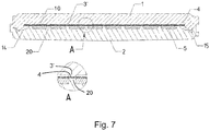
- Figure 6 shows a plan view of a variant of the crossflow filter device 17, again with internal features indicated by dashed lines, and Figure 7 shows a cross-section through the variant device along the line X-X.
- Figure 7 shows a cross-section through the variant device along the line X-X.
- Features common to the variant device and the device of Figures 1 to 5 have the same reference numbers.
- the variant device has rigid plastic guide walls 3' to define the path of the flow channel 10.
- the walls are part of the moulding that also forms the retentate-side plate 1, and are permanently ultrasonically welded to the filter membrane 4. This welding locally densifies the membrane across its full thickness to form a fluid tight seal which prevents any short-circuiting of the flow channel 10 by liquid on the flow path 10 from the inlet 7 to the outlet 8.
- support walls 20 project from the inner surface of the filtrate side plate 2 across the collection chamber and mirroring the line of the guide walls 3'. Conveniently, these support walls are part of the moulding that also forms the filtrate-side plate.
- the support walls penetrate through corresponding openings in the support body 5 and are also permanently joined to the filter membrane 4 by the ultrasonic welding.
- Figure 7 shows a magnified view A of the cross-section at one of the welds
Landscapes
- Chemical & Material Sciences (AREA)
- Chemical Kinetics & Catalysis (AREA)
- Engineering & Computer Science (AREA)
- Water Supply & Treatment (AREA)
- Separation Using Semi-Permeable Membranes (AREA)
Abstract
A crossflow filter device for filtering a pressurised feed liquid is provided. The crossflow filter device comprises: a filter membrane; a flow channel for the pressurised feed liquid which extends in a path over a retentate surface of the membrane such that the direction of flow in the channel is tangential to the retentate surface, and a filtrate derived from the feed liquid passes through the membrane leaving retentate liquid in the flow channel; and a collection chamber for the filtrate formed on an opposite, filtrate surface of the membrane. The crossflow filter device further comprises a sealed housing having a retentate side and a filtrate side which enclose therebetween the flow channel, the filter membrane and the collection chamber. The crossflow filter device further comprises, flow channel guide walls provided at an inner surface of the retentate side of the housing. The guide walls are configured to form a fluid tight seal with the filter membrane, and thereby define the path of the flow channel over the retentate surface of the membrane.
Description
- The present disclosure relates to the field of crossflow filter devices for filtering pressurised feed liquids.
- Crossflow filtration is a process in which a pressurised feed liquid is forced to flow tangentially over a membrane permeable to a filtrate derivable from the feed liquid. As the feed liquid flows over one side of the membrane, the filtrate passes through to the other side of the membrane, leaving behind a retentate liquid, which is the feed liquid depleted of filtrate. Media in the feed liquid that do not pass through the membrane are thus concentrated in the retentate liquid.
- Typically, the feed liquid flows in a cyclic manner into a crossflow filter device, over the membrane, and out again, with the media concentrating in the retentate liquid with each such cycle. The filtrate which has passed through the membrane exits the device through an outlet on the opposite side of the membrane. A flow restrictor at the retentate outlet is used to create pressure within the device.
- An example device is the Vivaflow 200™ available from Sartorius.
- The Vivaflow 200™ is formed as a cassette which has rigid, clear plastic, retentate-side and filtrate-side plates. These plates are thick enough to resist the stresses produced by the pressure of throughflowing liquids and are bolted together around their perimeters. The cassette housing thus-formed sealingly contains a flow channel for the feed liquid / retentate liquid, a permeable membrane, and a plate-like, porous support body which supports the membrane while allowing relatively unimpeded passage therethrough of liquids, such as the filtrate. The cassette further features an inlet in the retentate-side plate for the feed liquid to the flow channel, an outlet in the retentate-side plate for the retentate liquid from the flow channel, and a further outlet in the filtrate-side plate for the filtrate which has passed through the membrane and the support body. The flow channel shuttles back and forth over the retentate surface of the membrane, which helps to expose all the feed liquid to a large surface area of the membrane, and also introduces a convoluted path to create eddies and break up linear flow of the feed liquid, thus improving the filtration efficiency of the cassette.
- In the Vivaflow 200™, the flow channel is formed as a recess in the inner surface of the retentate-side plate. When the cassette is assembled, the retentate-side plate, membrane, support body and filtrate-side plate are stacked in that order, and the retentate-side and filtrate-side plates are then bolted together. As a result, the raised parts of the inner surface of the retentate-side plate which are outside the recess press against the membrane, and the front-to-back depth of the flow channel is just the depth of the recess. However, this arrangement, while being convenient to manufacture and confining the flow path of the feed liquid to the flow channel, allows some of the feed liquid to short-circuit the shuttling flow channel due to an incomplete seal being formed between the raised parts of the inner surface of the retentate-side plate and the membrane. Such short-circuiting impairs the filtration efficiency of the Vivaflow 200™.
- The Vivaflow 50™ is a similar, but smaller, crossflow filter device, also available from Sartorius. It performs the same function as the Vivaflow 200™ but has some constructional differences. For example, its retentate-side and filtrate-side plates are wedged into a thick plastic sleeve to press them together, and are sealed to each other with a perimeter O-ring.
- A need exists for a crossflow filter device that reduces or avoids such short-circuiting.
- According to a first aspect of the invention, there is provided a crossflow filter device for filtering a pressurised feed liquid;
wherein the crossflow filter device comprises: a filter membrane; a flow channel for the pressurised feed liquid which extends in a path over a retentate surface of the membrane such that the direction of flow in the channel is tangential to the retentate surface, and a filtrate derived from the feed liquid passes through the membrane leaving retentate liquid in the flow channel; and a collection chamber for the filtrate formed on an opposite, filtrate surface of the membrane;
wherein the crossflow filter device further comprises a sealed housing having a retentate side and a filtrate side which enclose therebetween the flow channel, the filter membrane and the collection chamber; and
wherein the crossflow filter device further comprises, flow channel guide walls provided at an inner surface of the retentate side of the housing, which guide walls are configured to form a fluid tight seal with the filter membrane and thereby define the path of the flow channel over the retentate surface of the membrane. - Advantageously, by providing guide walls which are configured to form a fluid tight seal with the filter membrane, the guide walls can provide effective sealing around the edges of the flow channel, and thereby substantially eliminate short-circuiting of the flow channel by the feed liquid.
- The crossflow filter device of the first aspect may have any one or any combination of the following optional features.
- According to one approach, the flow channel guide walls may be resiliently deformable. They can then deform and sealingly engage with the filter membrane to form the fluid tight seal. Advantageously, by providing guide walls which deform and sealingly engage on contact with the filter membrane, the guide walls can accommodate and seal to different types of membrane, such that different types of membrane can be used in the same basic device.
- Conveniently, the resiliently deformable flow channel guide walls may be formed of elastomer, such as thermoplastic poly-urethane (TPU), natural rubber, silicone rubber, polysilaxane, or latex. The guide walls may have a single component structure, or a multicomponent structure, for example a multilayer structure having layers formed of different materials such as different ones of the aforementioned elastomers.
- The resiliently deformable guide walls may be a separate component of the device from the housing, and therefore should be correctly presented thereto on assembly of the device. Conveniently, the inner surface of the retentate side of the housing may include a recess corresponding to the line of the guide walls and in which the resiliently deformable guide walls locate to sealingly engage with that inner surface. The recess can help to correctly position the guide walls on assembly of the device. Particularly if the guide walls are a snug fit in the recess, it may also help to improve the seal between the guide walls and the inner surface of the retentate side of the housing.
- Another option, however, is for the resiliently deformable guide walls to be permanently co-moulded into the retentate side of the housing during manufacture of these parts of the device. In this way, the guide walls become integral to the housing, and any problems of sealing the guide walls to the retentate side of the housing are avoided.
- The crossflow filter device comprising the resiliently deformable guide walls may further comprise one or more interconnecting members which extend across the afore-mentioned cavity, preferably outside the path of the flow channel, to join the inner surface of the retentate side of the housing to an inner surface of the filtrate side of the housing and thereby strengthen the housing. The interconnecting members may penetrate through openings in the membrane and, in devices comprising a foraminous support body (discussed below), may also penetrate through openings in the support body. The interconnecting members can strengthen the housing against the pressure of the throughflowing liquid, and thus allow the thickness of the housing to be reduced. This in turn can help to reduce manufacturing costs.
- The interconnecting members may, for example, be integrally formed as projections from the inner surface of one of the retentate and filtrate sides of the housing. They may be joined to the inner surface of the other side using any convenient process, such as ultrasonic welding. Another option, however, is for the interconnecting members to be integrally formed as pairs of projections from the inner surfaces of respectively the retentate and filtrate sides of the housing, each pair of projections meeting at the membrane. In this case, there may be no need for the interconnecting members to penetrate through openings in the membrane, i.e. each interconnecting member can be formed by a given pair of projections and a small region of membrane trapped therebetween.
- According to another approach, the guide walls may be welded to the filter membrane, the weld locally densifying the filter membrane across its entire thickness to form the fluid tight seal. For example, the weld can be formed by ultrasonic welding. As long as the membrane can be densified by welding, this option also allows the guide walls to seal to different types of membrane, such that different types of membrane can again be used in the same basic device.
- When the guide walls are welded to the filter membrane, the device may further comprise weld support members which extend from an inner surface of the filtrate side of the housing to support the welds. In particular, the weld support members may also be welded to the filter membrane. The welded guide walls and weld support members, as well as forming the fluid tight seal, can also help to strengthen the housing in the manner of the interconnecting members discussed above. In devices comprising a foraminous support body (discussed below), the weld support members may penetrate through openings in the support body. Conveniently the guide walls can be integrally formed with the retentate side of the housing and/or the weld support members can be integrally formed with the filtrate side of the housing.
- The guide walls may be configured such that the path for the flow channel shuttles back and forth over the retentate surface of the membrane. This improves filtration efficiency by forcing all the feed liquid to pass over a large area of the membrane, and helps to create eddies and turbulence to break up linear flow.
- The device may further comprise: an inlet to the flow channel for the feed liquid; an outlet from the flow channel for the retentate liquid; and an outlet from the collection chamber for the filtrate. In use, external tubes are typically attached to the device at the inlet and outlets, for example such that an external pump can cycle the feed liquid and retentate liquid through the device. Conveniently, the inlet to the flow channel and the outlet from the flow channel may be formed in the retentate side of the housing, and the outlet from the collection chamber may be formed in the filtrate side of the housing.
- One or more of the inlet and the outlets may include a respective rotating Luer cuff for connection to respective external tubing.
- The device may further comprise a foraminous support body located within the collection chamber, the support body providing mechanical support to the membrane while allowing relatively unimpeded passage therethrough of the filtrate, e.g. to a filtrate outlet. The support body may be made, for example, of porous plastic. It may be manufactured by sintering plastic particulate. However, other materials and/or manufacturing processes can be used. As an alternative to such a support body, protuberances integrally formed with the housing may project from an inner surface of the filtrate side of the housing to support the membrane, the protuberances allowing relatively unimpeded passage therebetween of the filtrate.
- The housing may be formed of transparent material. This allows the operation of the device to be visually monitored by a user. Conveniently, it can be formed of plastic material. However other types of material, such as glass, ceramic or metal may be used for the housing.
- The retentate side and filtrate side of the housing may be formed as respective plates which sandwich the flow channel guide walls, the filter membrane and the foraminous support body (if present) therebetween. In particular, the housing may have a retentate-side plate and a filtrate-side plate which are sealed together along respective sealing perimeters to form a cavity therebetween in which the guide walls, the filter membrane, and the foraminous support body (if present) are housed. An O-ring may be provided around the sealing perimeters to perfect the seal therebetween. The plates may be sealed together by various means, for example: ultrasonic welding, heat staking; gluing; or mechanical interference. The joining of the plates may be performed or supplemented by mechanical fasteners (e.g. screws, bolts, staples, clamps etc.), integral snap-fit connectors, and/or a wedge-fit mechanism. Another option is that the sealed housing further includes a moulded or overmoulded surround which joins the casings together.
- The device may further comprise complimentary formations located on opposing sides of the device and configured such that a formation on one side of a device can engage with the complimentary formation on the other side of another device such that plural devices can be joined together in a larger grouping. For example, the complimentary formations may include a pair of male and female formations such as a rail and a groove. The devices of such a larger grouping may be fluidly connected in parallel or in series to process larger volumes of feed liquid.
- The device may further comprise external support feet projecting from the filtrate side of the housing. When the feet are placed on a work surface (e.g. laboratory bench), the device is thereby raised from the surface giving improved access to e.g. its inlet and the outlets and particularly any rotating Luer cuff. Also by having the feet project from the filtrate side of the housing, the collection chamber will be below the filter membrane such that gravity can assist the passage of filtrate through the membrane.
- Embodiments of the present disclosure will now be described by way of example with reference to the accompanying drawings in which:
-
Figure 1 shows a perspective view of a sealed housing of a crossflow filter device; -
Figure 2 shows a first exploded view of the crossflow filter device ofFigure 1 ; -
Figure 3 shows a second exploded view of the crossflow filter device ofFigure 1 ; -
Figure 4 shows a third exploded view of the crossflow filter device ofFigure 1 ; -
Figure 5 shows a plan view of the crossflow filter device ofFigure 1 ; -
Figure 6 shows a plan view of a variant crossflow filter device; and -
Figure 7 shows a cross-section through the variant device along the line X-X ofFigure 6 . -
Figure 1 shows a perspective view of a sealed housing of acrossflow filter device 17, the housing comprising a retentate-side plate 1 and a filtrate-side plate 2 which define a cavity therebetween. Aninlet 7 for flow of a feed liquid into the cavity is formed in the retentate-side plate 1, anoutlet 8 for flow of aretentate liquid 8 out of the cavity is formed in the retentate-side plate 1, and anoutlet 9 for a flow of filtrate out of the cavity is formed in the filtrate-side plate 2. - The
feed liquid inlet 7 has a female Luer connection, while the retentateliquid outlet 8 and thefiltrate outlet 9 each has a male Luer connection with a respective rotatingLuer cuff 6. The Luer connections allow external tubing connectors to be attached to thedevice 17. -
Figures 2 to 4 are respective exploded views of thecrossflow filter device 17 ofFigure 1 .Figures 2 and4 allow the inner surface of the filtrate-side plate 2 to be seen, whileFigure 3 allows the inner surface of the retentate-side plate 1 to be seen. Thehousing plates channel guide walls 3, afilter membrane 4, and aforaminous support body 5. Theplates plates - The guide walls 3 (best shown in
Figure 2 ) are formed as a single piece elastomer moulding which, when engaged on one side with the inner surface of the retentate-side plate 1 and on the other side with thefilter membrane 4, defines the path of aflow channel 10 which shuttles back and forth over the retentate surface of themembrane 4 from theinlet 7 to theoutlet 8. To assist with the correct location of theguide walls 3 in thedevice 17, the inner surface of the retentate-side plate 1 has arecess 18 formed therein (shown inFigure 3 ), corresponding to the line of theguide walls 3 and into which the walls can be fitted. Alternatively, theguide walls 3 can be co-moulded to the retentate-side plate 1 such that the two parts are permanently integrated. - The
guide walls 3 are made of a medically-safe elastomer, such as TPU, natural rubber, silicone rubber, polysilaxane, or latex, which is highly resistant to leaching. This lowers or avoids any risk of contamination of filtrates and feed liquids / retentates flowing through thedevice 17. Theguide walls 3, being elastically compliant, adapt to and accommodate any irregularities in the retentate surface of thefilter membrane 4, forming a good seal around the edges of theflow channel 10. They thus substantially prevent any short-circuiting of theflow channel 10 by liquid on theflow path 10 from theinlet 7 to theoutlet 8. In addition, they can adapt to different types of membrane 4 (such as poly ether sulfone membranes, regenerated cellulose membranes, or cellulose acetate membranes), and can help to prevent damage to any surface treatment of themembrane 4, such as specialised receptors attached to the membrane). Thus the same basic filter device can be used in many different applications, simply by changing the membrane type. In particular, thedevice 17 can be used to scale-up or scale-down laboratory bench filtration, e.g. for the production of biopharmaceuticals such as antibodies. - The
foraminous support body 5 fills a collection chamber for the filtrate created by that part of the housing cavity between themembrane 4 and the inner surface of the filtrate-side plate 2. Thesupport body 5 physically supports themembrane 4 over substantially its entire area, allowing a pressure difference to be established across themembrane 4 that drives the flow of filtrate therethrough. The fora on thebody 5 are formed such that filtrate can pass through it relatively unimpeded en route from themembrane 4 to theoutlet 9 via the collection chamber. Conveniently, thebody 5 can be a porous plastic body formed by sintering plastic particulate. - In use, external tubing attached to the
feed liquid inlet 7 and the retentateliquid outlet 8 are joined to an external pump. Further external tubing attaches to thefiltrate outlet 9 and extends to a collection vessel. The pump continuously circulates a feed liquid into the device via theinlet 7, along theflow channel 10 defined by theguide walls 3, and back to the pump as retentate liquid from theoutlet 8. The direction of flow of the liquid in theflow channel 10 is tangential to the retentate surface of themembrane 4, and the pressure differential across themembrane 4 drives the flow of the filtrate derived from the feed liquid through themembrane 4. A flow restrictor (not shown) at theretentate outlet 9 is used to create the pressure within thedevice 17. - The shuttling back and forth of the
flow channel 10 forces all of the feed liquid to pass over a large surface area of the retentate surface of themembrane 4. It also creates eddies and turbulence in the feed liquid, which break up linear flow thereof. More specifically, the path of theflow channel 10 is comprised of a series of consecutive, anti-parallel linear runs that span a width of themembrane 4 and are connected by successive 180° degree turns.Figure 5 is a plan view of thecrossflow filter device 17, with internal features indicated by dashed lines, and best shows the path of theflow channel 10. - A result of operating the device is therefore that, as the pump circulates the feed liquid, filtrate derived from the feed liquid passes through the foraminous support body to collect in the collection vessel attached to the
filtrate outlet 9, and media in the feed liquid that do not pass through themembrane 4 concentrate in the retentate liquid. - To form the housing, the
housing plates perimeter groove 14 of one of the plates (in this example the filtrate-side plate 2, as shown inFigures 2 and4 ) and acorresponding perimeter ridge 15 of the other plate, (in this example the retentate-side plate 1, as shown inFigure 3 ). Theridge 15 fits into thegroove 14 and acts as an energy director allowing theplates guide walls 3,filter membrane 4, andsupport body 5 are located, with a suitable spacing between theplates guide walls 3 properly engage with thefilter membrane 4 and the inner surface of the retentate-side plate 1. Due to their deformability, theguide walls 3 allow variation in the stand-off between thefilter membrane 4 and the inner surface of the retentate-side plate 1. - However, to control this standoff, while also strengthening the housing against the pressures which it experiences in operation, interconnecting
members 16 may be provided to physically link the inner surfaces of thehousing plates members 16 penetrate, outside the path of theflow channel 10, through dedicated openings in themembrane 4 and in thesupport body 5. For example, the interconnectingmembers 16 can be formed as projections from the inner surface of one of the plates (in this example, the retentate-side plate 1), and on assembly of thedevice 17 can be joined to the inner surface of the other plate (in this example, the filtrate-side plate 2) by a suitable joining process. Conveniently, the interconnectingmembers 16 can act as further energy directors, allowing them to be ultrasonically welded to the other plate. By strengthening the housing, they allow the housing plates to be manufactured from thinner material than would otherwise be the case. - The filtrate-
side plate 2 has external feet 11 (shown inFigures 3 and4 ) at each of its corners on which thedevice 17 can rest. When thefeet 11 are placed on a work surface, thedevice 17 is supported such that the collection chamber lies directly below themembrane 4. This allows gravity to assist the flow of filtrate through themembrane 4. In addition, thefeet 11 raise the level of the entire device so that theLuer cuff 6 for theoutlet 9 can be rotated unimpeded. - Opposite edges of the housing have respectively a mounting
groove 12 and a mountingrail 13. These are configured such that the mountinggroove 12 of onedevice 17 can engage with the mountingrail 13 of asecond device 17, allowing a number ofdevices 17 to be joined together in a larger grouping, and then fluidly connected in series or in parallel to increase the ability to filter larger volumes. Each of the mountinggroove 12 and therail 13 is partly formed by one of theplates other plates -
Figure 6 shows a plan view of a variant of thecrossflow filter device 17, again with internal features indicated by dashed lines, andFigure 7 shows a cross-section through the variant device along the line X-X. Features common to the variant device and the device ofFigures 1 to 5 have the same reference numbers. - Instead of the resiliently deformable flow
channel guide walls 3, the variant device has rigidplastic guide walls 3' to define the path of theflow channel 10. The walls are part of the moulding that also forms the retentate-side plate 1, and are permanently ultrasonically welded to thefilter membrane 4. This welding locally densifies the membrane across its full thickness to form a fluid tight seal which prevents any short-circuiting of theflow channel 10 by liquid on theflow path 10 from theinlet 7 to theoutlet 8. - To support the welds,
support walls 20 project from the inner surface of thefiltrate side plate 2 across the collection chamber and mirroring the line of theguide walls 3'. Conveniently, these support walls are part of the moulding that also forms the filtrate-side plate. The support walls penetrate through corresponding openings in thesupport body 5 and are also permanently joined to thefilter membrane 4 by the ultrasonic welding.Figure 7 shows a magnified view A of the cross-section at one of the welds, - Advantageously, the
support walls 20, in combination with theguide walls 3', strengthen the housing in the same manner as the interconnectingmembers 16 of the device ofFigures 1 to 5 . - It will be understood that the invention is not limited to the embodiments above-described and various modifications and improvements can be made without departing from the concepts described herein. Except where mutually exclusive, any of the features may be employed separately or in combination with any other features and the disclosure extends to and includes all combinations and sub-combinations of one or more features described herein.
Claims (15)
- A crossflow filter device (17) for filtering a pressurised feed liquid;
wherein the crossflow filter device comprises: a filter membrane (4); a flow channel (10) for the pressurised feed liquid which extends in a path over a retentate surface of the membrane such that the direction of flow in the channel is tangential to the retentate surface, and a filtrate derived from the feed liquid passes through the membrane leaving retentate liquid in the flow channel; and a collection chamber for the filtrate formed on an opposite, filtrate surface of the membrane;
wherein the crossflow filter device further comprises a sealed housing having a retentate side (1) and a filtrate side (2) which enclose therebetween the flow channel (10), the filter membrane (4) and the collection chamber; and
wherein the crossflow filter device further comprises flow channel guide walls (3, 3') provided at an inner surface of the retentate side (1) of the housing, which guide walls are configured to form a fluid tight seal with the filter membrane (4) and thereby define the path of the flow channel (10) over the retentate surface of the membrane. - The crossflow filter device (17) according claim 1 wherein the flow channel guide walls (3), which are resiliently deformable, deform and sealingly engage with the filter membrane (4) to form the fluid tight seal.
- The crossflow filter device (17) according claim 2 wherein the inner surface of the retentate side (1) of the housing includes a recess (18) corresponding to the line of the guide walls (3) and in which the guide walls locate to sealingly engage with the inner surface of the retentate side of the housing.
- The crossflow filter device (17) according to claim 2 wherein the guide walls (3) are permanently co-moulded into the retentate side of the housing.
- The crossflow filter device (17) according to any one of claims 2 to 4 which further comprises one or more interconnecting members (16) which extend across the cavity outside the path of the flow channel (10) to join the inner surface of the retentate side (1) of the housing to an inner surface of the filtrate side (2) of the housing and thereby strengthen the housing.
- The crossflow filter device (17) according to claim 5 wherein the interconnecting members (16) penetrate through openings in the membrane (4).
- The crossflow filter device (17) according claim 1 wherein the guide walls (3') are welded to the filter membrane (4), the weld locally densifying the filter membrane across its entire thickness to form the fluid tight seal.
- The crossflow filter device (17) according claim 7 wherein the device further comprises weld support members (20) which extend from an inner surface of the filtrate side (2) of the housing to support the welds.
- The crossflow filter device (17) according claim 8 wherein the weld support members (20) are also welded to the filter membrane (4).
- The crossflow filter device (17) according to any one of the previous claims wherein the guide walls (3) are configured such that the path for the flow channel (10) shuttles back and forth over the retentate surface of the membrane (4).
- The crossflow filter device (17) according to any one of the previous claims wherein the housing includes: an inlet (7) to the flow channel (10) for the feed liquid; an outlet (8) from the flow channel for the retentate liquid; and an outlet (9) from the collection chamber for the filtrate.
- The crossflow filter device (17) according to any of the previous claims which further comprises a foraminous support body (5) located within the collection chamber, the support body providing mechanical support to the membrane (4) while allowing relatively unimpeded passage therethrough of the filtrate.
- The crossflow filter device (17) according to any of the previous claims wherein the housing has a retentate-side plate (1) and a filtrate-side plate (2) which are sealed together along respective sealing perimeters to form a cavity therebetween in which the guide walls (3) and the filter membrane (4) are housed.
- The crossflow filter device (17) according to any of the previous claims wherein the device further comprises complimentary formations (12, 13) located on opposing sides of the device and configured such that a formation on one side of a device can engage with the complimentary formation on the other side of another device such that plural devices can be joined together in a larger grouping.
- The crossflow filter device (17) according to any of the previous claims wherein the device further comprises legs (11) situated on the sealed housing.
Priority Applications (9)
| Application Number | Priority Date | Filing Date | Title |
|---|---|---|---|
| EP19159491.0A EP3702017A1 (en) | 2019-02-26 | 2019-02-26 | Crossflow filter device |
| JP2021550097A JP7314295B2 (en) | 2019-02-26 | 2020-02-18 | Cross flow filter device |
| EP20704550.1A EP3930878B1 (en) | 2019-02-26 | 2020-02-18 | Crossflow filter device |
| KR1020217030587A KR20210127997A (en) | 2019-02-26 | 2020-02-18 | cross flow filter device |
| ES20704550T ES3038016T3 (en) | 2019-02-26 | 2020-02-18 | Crossflow filter device |
| PCT/EP2020/054265 WO2020173762A1 (en) | 2019-02-26 | 2020-02-18 | Crossflow filter device |
| DK20704550.1T DK3930878T3 (en) | 2019-02-26 | 2020-02-18 | CROSS-FILTERING DEVICE |
| US17/426,582 US12048896B2 (en) | 2019-02-26 | 2020-02-18 | Crossflow filter device |
| CN202080016770.9A CN113507982B (en) | 2019-02-26 | 2020-02-18 | Cross flow filtration device |
Applications Claiming Priority (1)
| Application Number | Priority Date | Filing Date | Title |
|---|---|---|---|
| EP19159491.0A EP3702017A1 (en) | 2019-02-26 | 2019-02-26 | Crossflow filter device |
Publications (1)
| Publication Number | Publication Date |
|---|---|
| EP3702017A1 true EP3702017A1 (en) | 2020-09-02 |
Family
ID=65598575
Family Applications (2)
| Application Number | Title | Priority Date | Filing Date |
|---|---|---|---|
| EP19159491.0A Withdrawn EP3702017A1 (en) | 2019-02-26 | 2019-02-26 | Crossflow filter device |
| EP20704550.1A Active EP3930878B1 (en) | 2019-02-26 | 2020-02-18 | Crossflow filter device |
Family Applications After (1)
| Application Number | Title | Priority Date | Filing Date |
|---|---|---|---|
| EP20704550.1A Active EP3930878B1 (en) | 2019-02-26 | 2020-02-18 | Crossflow filter device |
Country Status (8)
| Country | Link |
|---|---|
| US (1) | US12048896B2 (en) |
| EP (2) | EP3702017A1 (en) |
| JP (1) | JP7314295B2 (en) |
| KR (1) | KR20210127997A (en) |
| CN (1) | CN113507982B (en) |
| DK (1) | DK3930878T3 (en) |
| ES (1) | ES3038016T3 (en) |
| WO (1) | WO2020173762A1 (en) |
Families Citing this family (9)
| Publication number | Priority date | Publication date | Assignee | Title |
|---|---|---|---|---|
| CN108744983B (en) * | 2018-09-03 | 2023-04-07 | 杭州海纳环保技术有限公司 | Reverse osmosis and nanofiltration membrane component |
| US11259821B2 (en) | 2019-12-18 | 2022-03-01 | Imperative Care, Inc. | Aspiration system with accelerated response |
| CN112553054A (en) * | 2020-12-10 | 2021-03-26 | 上海艾众生物科技有限公司 | Cell separation apparatus for bioreactor |
| EP4108318A1 (en) | 2021-06-22 | 2022-12-28 | Sartorius Stedim Lab Ltd. | Crossflow filter device |
| USD1077996S1 (en) * | 2021-10-18 | 2025-06-03 | Imperative Care, Inc. | Inline fluid filter |
| CN114558455B (en) * | 2022-01-14 | 2023-05-02 | 杭州科百特过滤器材有限公司 | Virus filter |
| CN115672042A (en) * | 2022-10-24 | 2023-02-03 | 杭州科百特过滤器材有限公司 | A cartridge filter assembly |
| CN121240918A (en) * | 2023-03-31 | 2025-12-30 | 唐纳森公司 | Fluid filter cartridge assembly |
| EP4454739A1 (en) * | 2023-04-28 | 2024-10-30 | Sartorius Stedim Biotech GmbH | Filtration device, in particular small-scale filtration device for production of biopharmaceuticals |
Citations (4)
| Publication number | Priority date | Publication date | Assignee | Title |
|---|---|---|---|---|
| US5342517A (en) * | 1987-10-02 | 1994-08-30 | Kopf Henry B | Filtration cassette article, and filter comprising same |
| US5593580A (en) * | 1986-11-26 | 1997-01-14 | Kopf; Henry B. | Filtration cassette article, and filter comprising same |
| US5601727A (en) * | 1991-11-04 | 1997-02-11 | Pall Corporation | Device and method for separating plasma from a biological fluid |
| US6312591B1 (en) * | 1997-09-10 | 2001-11-06 | Sartorius Ag | Filtration cell for tangential flow filtration and filtration system making use of such cell |
Family Cites Families (17)
| Publication number | Priority date | Publication date | Assignee | Title |
|---|---|---|---|---|
| US4025425A (en) * | 1975-09-29 | 1977-05-24 | Dresser Industries, Inc. | Purification apparatus |
| JPS5935631B2 (en) | 1980-07-24 | 1984-08-29 | テルモ株式会社 | Body fluid “filtration” device |
| JPS5935631A (en) | 1982-08-19 | 1984-02-27 | Kawasaki Steel Corp | Manufacture of steel plate for enamel |
| DE3712872A1 (en) * | 1986-04-18 | 1987-10-22 | Sartorius Gmbh | FILTER ELEMENT FOR FLUIDS AND METHOD FOR PRODUCING A FILTER ELEMENT |
| US6514412B1 (en) * | 1998-06-18 | 2003-02-04 | 3M Innovative Properties Company | Microstructured separation device |
| SE9900530D0 (en) | 1999-02-15 | 1999-02-15 | Vincenzo Vassarotti | A device for concentrating and / or purifying macromolecules in a solution and a method for manufacturing such a device |
| FI114617B (en) * | 1999-07-09 | 2004-11-30 | Steris Europe Inc | Filter unit and procedure for its sealing |
| JP2003126864A (en) | 2001-10-30 | 2003-05-07 | Matsushita Electric Ind Co Ltd | Gasket for electrodialysis apparatus and electrodialysis apparatus using the same |
| KR100547074B1 (en) * | 2001-11-05 | 2006-01-31 | 아사히 가세이 가부시키가이샤 | Hollow fiber membrane module |
| US7306727B2 (en) * | 2004-09-21 | 2007-12-11 | Millipore Corporation | Disposable tangential flow filtration device holder |
| US8128822B2 (en) * | 2004-10-06 | 2012-03-06 | State Of Oregon Acting By And Through The State Board Of Higher Education On Behalf Of Oregon State University | MECS dialyzer |
| DE102008012305A1 (en) | 2008-03-03 | 2009-09-17 | Microdyn - Nadir Gmbh | Filtration device for micro, ultra and nanofiltration |
| CN203355467U (en) * | 2013-06-24 | 2013-12-25 | 岳阳长炼建安石化配件制造有限公司 | Molecular sieve filtering equipment with kettle type cross-flow molecular sieve filtering device |
| US9808767B2 (en) * | 2013-10-31 | 2017-11-07 | Toray Industries, Inc. | Separation membrane element |
| CN104014246B (en) * | 2014-06-27 | 2016-08-24 | 南京九思高科技有限公司 | A kind of double diaphragm cross-flow filtration plate film assembly |
| CA2883468A1 (en) * | 2015-03-03 | 2016-09-03 | Oleh Kutowy | Used lubricaton oil purification process and apparatus |
| CA3025353A1 (en) * | 2016-05-27 | 2017-11-30 | The Charles Stark Draper Laboratory, Inc. | Biomimetic microfluidic device for high efficiency carbon dioxide removal from patients at low blood flow rates |
-
2019
- 2019-02-26 EP EP19159491.0A patent/EP3702017A1/en not_active Withdrawn
-
2020
- 2020-02-18 ES ES20704550T patent/ES3038016T3/en active Active
- 2020-02-18 DK DK20704550.1T patent/DK3930878T3/en active
- 2020-02-18 KR KR1020217030587A patent/KR20210127997A/en active Pending
- 2020-02-18 WO PCT/EP2020/054265 patent/WO2020173762A1/en not_active Ceased
- 2020-02-18 US US17/426,582 patent/US12048896B2/en active Active
- 2020-02-18 JP JP2021550097A patent/JP7314295B2/en active Active
- 2020-02-18 EP EP20704550.1A patent/EP3930878B1/en active Active
- 2020-02-18 CN CN202080016770.9A patent/CN113507982B/en active Active
Patent Citations (4)
| Publication number | Priority date | Publication date | Assignee | Title |
|---|---|---|---|---|
| US5593580A (en) * | 1986-11-26 | 1997-01-14 | Kopf; Henry B. | Filtration cassette article, and filter comprising same |
| US5342517A (en) * | 1987-10-02 | 1994-08-30 | Kopf Henry B | Filtration cassette article, and filter comprising same |
| US5601727A (en) * | 1991-11-04 | 1997-02-11 | Pall Corporation | Device and method for separating plasma from a biological fluid |
| US6312591B1 (en) * | 1997-09-10 | 2001-11-06 | Sartorius Ag | Filtration cell for tangential flow filtration and filtration system making use of such cell |
Also Published As
| Publication number | Publication date |
|---|---|
| JP2022521795A (en) | 2022-04-12 |
| CN113507982B (en) | 2024-12-31 |
| US12048896B2 (en) | 2024-07-30 |
| US20220161198A1 (en) | 2022-05-26 |
| KR20210127997A (en) | 2021-10-25 |
| JP7314295B2 (en) | 2023-07-25 |
| EP3930878A1 (en) | 2022-01-05 |
| CN113507982A (en) | 2021-10-15 |
| ES3038016T3 (en) | 2025-10-08 |
| DK3930878T3 (en) | 2025-08-25 |
| WO2020173762A1 (en) | 2020-09-03 |
| EP3930878B1 (en) | 2025-07-16 |
Similar Documents
| Publication | Publication Date | Title |
|---|---|---|
| EP3702017A1 (en) | Crossflow filter device | |
| KR102039199B1 (en) | Modular filter cassette | |
| US4430218A (en) | Separating device for fluids, consisting of support plates and cut sections of a semi-permeable diaphragm | |
| US5258122A (en) | Cross-flow filter device with pressure-balancing feature | |
| WO2002076529A1 (en) | Blood processing device | |
| CN104334259A (en) | Hollow fiber membrane module, manufacturing method of hollow fiber membrane module, and hollow fiber membrane unit having hollow fiber membrane module | |
| JP2016030257A (en) | Filter module for dead-end and cross-flow filtration | |
| EP0111423B1 (en) | Transfer membrane apparatus | |
| US20240286083A1 (en) | Crossflow filter device | |
| JP2015120149A (en) | Fluid filter with multiple parallel filter elements, and related methods | |
| CN102405070B (en) | For the treatment of the device of medical fluid, external functional device and treatment facility | |
| JPWO2011148768A1 (en) | Filtration membrane module | |
| US4318813A (en) | Membrane plasmapheresis module | |
| US4636312A (en) | Plasmapheresis filtration module having improved end plate | |
| CN106163644A (en) | Screen plate assembly | |
| JPS62258708A (en) | Flat-plate thin membrane laminate type filter | |
| AU2020418832B2 (en) | Filtration cassette residing in bag and methods of using same | |
| CN219409366U (en) | Shell and filter element | |
| CA1252737A (en) | Plasmapheresis filtration module | |
| CN120936433A (en) | Flat membrane module | |
| EP0089434A2 (en) | Plasmapheresis filtration module | |
| JPS58143762A (en) | Filter module for sending out blood serum |
Legal Events
| Date | Code | Title | Description |
|---|---|---|---|
| PUAI | Public reference made under article 153(3) epc to a published international application that has entered the european phase |
Free format text: ORIGINAL CODE: 0009012 |
|
| STAA | Information on the status of an ep patent application or granted ep patent |
Free format text: STATUS: THE APPLICATION HAS BEEN PUBLISHED |
|
| AK | Designated contracting states |
Kind code of ref document: A1 Designated state(s): AL AT BE BG CH CY CZ DE DK EE ES FI FR GB GR HR HU IE IS IT LI LT LU LV MC MK MT NL NO PL PT RO RS SE SI SK SM TR |
|
| AX | Request for extension of the european patent |
Extension state: BA ME |
|
| STAA | Information on the status of an ep patent application or granted ep patent |
Free format text: STATUS: THE APPLICATION IS DEEMED TO BE WITHDRAWN |
|
| 18D | Application deemed to be withdrawn |
Effective date: 20210303 |