EP3702015A1 - Gas treatment method and gas treatment apparatus - Google Patents
Gas treatment method and gas treatment apparatus Download PDFInfo
- Publication number
- EP3702015A1 EP3702015A1 EP18882476.7A EP18882476A EP3702015A1 EP 3702015 A1 EP3702015 A1 EP 3702015A1 EP 18882476 A EP18882476 A EP 18882476A EP 3702015 A1 EP3702015 A1 EP 3702015A1
- Authority
- EP
- European Patent Office
- Prior art keywords
- gas
- treatment liquid
- regenerator
- acidic compound
- absorber
- Prior art date
- Legal status (The legal status is an assumption and is not a legal conclusion. Google has not performed a legal analysis and makes no representation as to the accuracy of the status listed.)
- Granted
Links
Images






Classifications
-
- B—PERFORMING OPERATIONS; TRANSPORTING
- B01—PHYSICAL OR CHEMICAL PROCESSES OR APPARATUS IN GENERAL
- B01D—SEPARATION
- B01D53/00—Separation of gases or vapours; Recovering vapours of volatile solvents from gases; Chemical or biological purification of waste gases, e.g. engine exhaust gases, smoke, fumes, flue gases, aerosols
- B01D53/14—Separation of gases or vapours; Recovering vapours of volatile solvents from gases; Chemical or biological purification of waste gases, e.g. engine exhaust gases, smoke, fumes, flue gases, aerosols by absorption
- B01D53/1425—Regeneration of liquid absorbents
-
- B—PERFORMING OPERATIONS; TRANSPORTING
- B01—PHYSICAL OR CHEMICAL PROCESSES OR APPARATUS IN GENERAL
- B01D—SEPARATION
- B01D53/00—Separation of gases or vapours; Recovering vapours of volatile solvents from gases; Chemical or biological purification of waste gases, e.g. engine exhaust gases, smoke, fumes, flue gases, aerosols
- B01D53/34—Chemical or biological purification of waste gases
- B01D53/96—Regeneration, reactivation or recycling of reactants
-
- B—PERFORMING OPERATIONS; TRANSPORTING
- B01—PHYSICAL OR CHEMICAL PROCESSES OR APPARATUS IN GENERAL
- B01D—SEPARATION
- B01D53/00—Separation of gases or vapours; Recovering vapours of volatile solvents from gases; Chemical or biological purification of waste gases, e.g. engine exhaust gases, smoke, fumes, flue gases, aerosols
- B01D53/14—Separation of gases or vapours; Recovering vapours of volatile solvents from gases; Chemical or biological purification of waste gases, e.g. engine exhaust gases, smoke, fumes, flue gases, aerosols by absorption
-
- B—PERFORMING OPERATIONS; TRANSPORTING
- B01—PHYSICAL OR CHEMICAL PROCESSES OR APPARATUS IN GENERAL
- B01D—SEPARATION
- B01D53/00—Separation of gases or vapours; Recovering vapours of volatile solvents from gases; Chemical or biological purification of waste gases, e.g. engine exhaust gases, smoke, fumes, flue gases, aerosols
- B01D53/14—Separation of gases or vapours; Recovering vapours of volatile solvents from gases; Chemical or biological purification of waste gases, e.g. engine exhaust gases, smoke, fumes, flue gases, aerosols by absorption
- B01D53/1456—Removing acid components
- B01D53/1475—Removing carbon dioxide
-
- B—PERFORMING OPERATIONS; TRANSPORTING
- B01—PHYSICAL OR CHEMICAL PROCESSES OR APPARATUS IN GENERAL
- B01D—SEPARATION
- B01D53/00—Separation of gases or vapours; Recovering vapours of volatile solvents from gases; Chemical or biological purification of waste gases, e.g. engine exhaust gases, smoke, fumes, flue gases, aerosols
- B01D53/14—Separation of gases or vapours; Recovering vapours of volatile solvents from gases; Chemical or biological purification of waste gases, e.g. engine exhaust gases, smoke, fumes, flue gases, aerosols by absorption
- B01D53/1456—Removing acid components
- B01D53/1481—Removing sulfur dioxide or sulfur trioxide
-
- B—PERFORMING OPERATIONS; TRANSPORTING
- B01—PHYSICAL OR CHEMICAL PROCESSES OR APPARATUS IN GENERAL
- B01D—SEPARATION
- B01D53/00—Separation of gases or vapours; Recovering vapours of volatile solvents from gases; Chemical or biological purification of waste gases, e.g. engine exhaust gases, smoke, fumes, flue gases, aerosols
- B01D53/14—Separation of gases or vapours; Recovering vapours of volatile solvents from gases; Chemical or biological purification of waste gases, e.g. engine exhaust gases, smoke, fumes, flue gases, aerosols by absorption
- B01D53/1493—Selection of liquid materials for use as absorbents
-
- B—PERFORMING OPERATIONS; TRANSPORTING
- B01—PHYSICAL OR CHEMICAL PROCESSES OR APPARATUS IN GENERAL
- B01D—SEPARATION
- B01D53/00—Separation of gases or vapours; Recovering vapours of volatile solvents from gases; Chemical or biological purification of waste gases, e.g. engine exhaust gases, smoke, fumes, flue gases, aerosols
- B01D53/14—Separation of gases or vapours; Recovering vapours of volatile solvents from gases; Chemical or biological purification of waste gases, e.g. engine exhaust gases, smoke, fumes, flue gases, aerosols by absorption
- B01D53/18—Absorbing units; Liquid distributors therefor
-
- B—PERFORMING OPERATIONS; TRANSPORTING
- B01—PHYSICAL OR CHEMICAL PROCESSES OR APPARATUS IN GENERAL
- B01D—SEPARATION
- B01D53/00—Separation of gases or vapours; Recovering vapours of volatile solvents from gases; Chemical or biological purification of waste gases, e.g. engine exhaust gases, smoke, fumes, flue gases, aerosols
- B01D53/34—Chemical or biological purification of waste gases
- B01D53/46—Removing components of defined structure
- B01D53/48—Sulfur compounds
-
- B—PERFORMING OPERATIONS; TRANSPORTING
- B01—PHYSICAL OR CHEMICAL PROCESSES OR APPARATUS IN GENERAL
- B01D—SEPARATION
- B01D53/00—Separation of gases or vapours; Recovering vapours of volatile solvents from gases; Chemical or biological purification of waste gases, e.g. engine exhaust gases, smoke, fumes, flue gases, aerosols
- B01D53/34—Chemical or biological purification of waste gases
- B01D53/46—Removing components of defined structure
- B01D53/48—Sulfur compounds
- B01D53/50—Sulfur oxides
-
- B—PERFORMING OPERATIONS; TRANSPORTING
- B01—PHYSICAL OR CHEMICAL PROCESSES OR APPARATUS IN GENERAL
- B01D—SEPARATION
- B01D53/00—Separation of gases or vapours; Recovering vapours of volatile solvents from gases; Chemical or biological purification of waste gases, e.g. engine exhaust gases, smoke, fumes, flue gases, aerosols
- B01D53/34—Chemical or biological purification of waste gases
- B01D53/46—Removing components of defined structure
- B01D53/48—Sulfur compounds
- B01D53/50—Sulfur oxides
- B01D53/507—Sulfur oxides by treating the gases with other liquids
-
- B—PERFORMING OPERATIONS; TRANSPORTING
- B01—PHYSICAL OR CHEMICAL PROCESSES OR APPARATUS IN GENERAL
- B01D—SEPARATION
- B01D53/00—Separation of gases or vapours; Recovering vapours of volatile solvents from gases; Chemical or biological purification of waste gases, e.g. engine exhaust gases, smoke, fumes, flue gases, aerosols
- B01D53/34—Chemical or biological purification of waste gases
- B01D53/46—Removing components of defined structure
- B01D53/62—Carbon oxides
-
- B—PERFORMING OPERATIONS; TRANSPORTING
- B01—PHYSICAL OR CHEMICAL PROCESSES OR APPARATUS IN GENERAL
- B01D—SEPARATION
- B01D53/00—Separation of gases or vapours; Recovering vapours of volatile solvents from gases; Chemical or biological purification of waste gases, e.g. engine exhaust gases, smoke, fumes, flue gases, aerosols
- B01D53/34—Chemical or biological purification of waste gases
- B01D53/46—Removing components of defined structure
- B01D53/68—Halogens or halogen compounds
-
- B—PERFORMING OPERATIONS; TRANSPORTING
- B01—PHYSICAL OR CHEMICAL PROCESSES OR APPARATUS IN GENERAL
- B01D—SEPARATION
- B01D53/00—Separation of gases or vapours; Recovering vapours of volatile solvents from gases; Chemical or biological purification of waste gases, e.g. engine exhaust gases, smoke, fumes, flue gases, aerosols
- B01D53/34—Chemical or biological purification of waste gases
- B01D53/74—General processes for purification of waste gases; Apparatus or devices specially adapted therefor
- B01D53/77—Liquid phase processes
- B01D53/78—Liquid phase processes with gas-liquid contact
-
- B—PERFORMING OPERATIONS; TRANSPORTING
- B01—PHYSICAL OR CHEMICAL PROCESSES OR APPARATUS IN GENERAL
- B01D—SEPARATION
- B01D2252/00—Absorbents, i.e. solvents and liquid materials for gas absorption
- B01D2252/20—Organic absorbents
- B01D2252/202—Alcohols or their derivatives
-
- B—PERFORMING OPERATIONS; TRANSPORTING
- B01—PHYSICAL OR CHEMICAL PROCESSES OR APPARATUS IN GENERAL
- B01D—SEPARATION
- B01D2252/00—Absorbents, i.e. solvents and liquid materials for gas absorption
- B01D2252/20—Organic absorbents
- B01D2252/202—Alcohols or their derivatives
- B01D2252/2023—Glycols, diols or their derivatives
- B01D2252/2026—Polyethylene glycol, ethers or esters thereof, e.g. Selexol
-
- B—PERFORMING OPERATIONS; TRANSPORTING
- B01—PHYSICAL OR CHEMICAL PROCESSES OR APPARATUS IN GENERAL
- B01D—SEPARATION
- B01D2252/00—Absorbents, i.e. solvents and liquid materials for gas absorption
- B01D2252/20—Organic absorbents
- B01D2252/204—Amines
- B01D2252/20405—Monoamines
-
- B—PERFORMING OPERATIONS; TRANSPORTING
- B01—PHYSICAL OR CHEMICAL PROCESSES OR APPARATUS IN GENERAL
- B01D—SEPARATION
- B01D2252/00—Absorbents, i.e. solvents and liquid materials for gas absorption
- B01D2252/20—Organic absorbents
- B01D2252/204—Amines
- B01D2252/20421—Primary amines
-
- B—PERFORMING OPERATIONS; TRANSPORTING
- B01—PHYSICAL OR CHEMICAL PROCESSES OR APPARATUS IN GENERAL
- B01D—SEPARATION
- B01D2252/00—Absorbents, i.e. solvents and liquid materials for gas absorption
- B01D2252/20—Organic absorbents
- B01D2252/204—Amines
- B01D2252/20426—Secondary amines
-
- B—PERFORMING OPERATIONS; TRANSPORTING
- B01—PHYSICAL OR CHEMICAL PROCESSES OR APPARATUS IN GENERAL
- B01D—SEPARATION
- B01D2252/00—Absorbents, i.e. solvents and liquid materials for gas absorption
- B01D2252/20—Organic absorbents
- B01D2252/204—Amines
- B01D2252/20431—Tertiary amines
-
- B—PERFORMING OPERATIONS; TRANSPORTING
- B01—PHYSICAL OR CHEMICAL PROCESSES OR APPARATUS IN GENERAL
- B01D—SEPARATION
- B01D2252/00—Absorbents, i.e. solvents and liquid materials for gas absorption
- B01D2252/20—Organic absorbents
- B01D2252/204—Amines
- B01D2252/20478—Alkanolamines
-
- B—PERFORMING OPERATIONS; TRANSPORTING
- B01—PHYSICAL OR CHEMICAL PROCESSES OR APPARATUS IN GENERAL
- B01D—SEPARATION
- B01D2252/00—Absorbents, i.e. solvents and liquid materials for gas absorption
- B01D2252/20—Organic absorbents
- B01D2252/204—Amines
- B01D2252/20478—Alkanolamines
- B01D2252/20484—Alkanolamines with one hydroxyl group
-
- B—PERFORMING OPERATIONS; TRANSPORTING
- B01—PHYSICAL OR CHEMICAL PROCESSES OR APPARATUS IN GENERAL
- B01D—SEPARATION
- B01D2257/00—Components to be removed
- B01D2257/20—Halogens or halogen compounds
- B01D2257/204—Inorganic halogen compounds
- B01D2257/2045—Hydrochloric acid
-
- B—PERFORMING OPERATIONS; TRANSPORTING
- B01—PHYSICAL OR CHEMICAL PROCESSES OR APPARATUS IN GENERAL
- B01D—SEPARATION
- B01D2257/00—Components to be removed
- B01D2257/30—Sulfur compounds
- B01D2257/302—Sulfur oxides
-
- B—PERFORMING OPERATIONS; TRANSPORTING
- B01—PHYSICAL OR CHEMICAL PROCESSES OR APPARATUS IN GENERAL
- B01D—SEPARATION
- B01D2257/00—Components to be removed
- B01D2257/50—Carbon oxides
- B01D2257/504—Carbon dioxide
Definitions
- the present invention relates to a gas treatment method and a gas treatment apparatus.
- a known gas treatment method brings a gas to be treated containing an acidic compound into contact with a treatment liquid, to separate the acidic compound.
- An exemplary gas treatment method disclosed in Patent Literature 1 below employs a gas treatment apparatus having an absorber and a regenerator.
- the absorber brings the gas to be treated into contact with the treatment liquid, so as to make the treatment liquid absorb the acidic compound in the gas to be treated.
- the regenerator heats the treatment liquid, to thereby separate the acidic compound from the treatment liquid.
- the conventional gas treatment method can recover carbon dioxide, by bringing, in the absorber, carbon dioxide into contact with the treatment liquid so as to be absorbed therein, and then by heating the treatment liquid in the regenerator.
- Energy required in this process typically amounts 4 GJ/ton-CO2.
- the present inventors have developed a technology for regenerating carbon dioxide at a temperature lower than before, by using an absorbent that can cause phase separation upon absorbing carbon dioxide.
- the present inventors have also confirmed that the energy could be reduced down to 1.5 GJ/ton-CO2 with combination of a heat-pump.
- Patent Literature 1 JP 2011-213494 A
- An object of the present invention is to reduce the energy required for separating and recovering the acidic compound.
- a gas treatment method including an absorption step in which a gas to be treated containing an acidic compound is brought into contact, in an absorber, with a treatment liquid absorbing the acidic compound, and a regeneration step in which the treatment liquid, having the acidic compound absorbed therein, is sent to a regenerator, and the treatment liquid is then heated to separate the acidic compound from the treatment liquid.
- a gas almost insoluble to the treatment liquid being fed to the regenerator, and the gas almost insoluble to the treatment liquid being then brought into contact with the treatment liquid.
- a gas treatment apparatus that uses a gas to be treated containing an acidic compound, and a treatment liquid for absorbing the acidic compound, to thereby separate the acidic compound from the gas to be treated
- the gas treatment apparatus including an absorber configured to bring the treatment liquid into contact with the gas to be treated, a regenerator configured to heat the treatment liquid, having been brought into contact in the absorber with the gas to be treated, to thereby separate the acidic compound, and a gas feeding unit for feeding a gas almost insoluble to the treatment liquid to the regenerator.
- a gas treatment apparatus 10 is used for separating an acidic compound from a gas to be treated containing the acidic compound, using a treatment liquid.
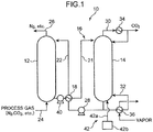
- the gas treatment apparatus 10 has, as illustrated in FIG. 1 , an absorber 12, a regenerator 14, a circulation channel 16, and a heat exchanger 18.
- the circulation channel 16 includes a first flow channel 21 through which the treatment liquid drawn out from the absorber 12 is fed into the regenerator 14, and a second flow channel 22 through which the treatment liquid drawn out from the regenerator 14 is returned back to the absorption liquid.
- the heat exchanger 18 is omissible.
- the absorber 12 has, connected thereto, a feed channel 24 through which the gas to be treated such as process gas is fed, a gas discharge channel 26 through which a gas after processed is discharged, the first flow channel 21 through which the treatment liquid is fed to the regenerator 14, and a second flow channel 22 through which the treatment liquid is returned from the regenerator 14 back into the absorber 12.
- the feed channel 24 is connected to the bottom end of the absorber 12.
- the gas discharge channel 26 is connected to the top end of the absorber 12.
- the first flow channel 21 is connected to the bottom end or the vicinity of the bottom end of the absorber 12. That is, the first flow channel 21 is connected to the absorber 12 at a point where the treatment liquid pooled in the absorber 12 can be drawn out.
- the second flow channel 22 is connected to the top end or the vicinity of the top end of the absorber 12. That is, the second flow channel 22 is connected to the absorber 12 at a point where the treatment liquid returned from the regenerator 14 can fall from above.
- the gas to be treated and the treatment liquid are brought into contact, and thereby the acidic compound contained in the gas to be treated is separated from the gas to be treated and absorbed in the treatment liquid. After all, the gas freed from the acidic compound is discharged from the absorber 12.
- This sort of absorber 12 may have any structure so long as it can bring the gas to be treated in to contact continuously with the treatment liquid, and may employ a reactor configured so as to spray the treatment liquid in the flow channel of the gas to be treated, configured so as to allow the treatment liquid to flow down through a filler arranged in the flow channel of the gas to be treated, or configured so as to introduce the gas to be treated and the treatment liquid individually into a large number of fine flow channels, and then combining such fine flow channels for the gas to be treated and the fine flow channels for the treatment liquid.
- Absorption of the acidic compound that takes place in the absorber 12 is an exothermic reaction. Carbon dioxide, when representing the acidic compound, gives a calorific value of approximately 1.8 GJ per ton of absorption.
- the reaction heat generated in the absorber 12 elevates temperature of the gas to be treated and the treatment liquid.
- the regenerator 14 has, connected thereto, the first flow channel 21 and the second flow channel 22.
- the first flow channel 21 is connected to top part of the regenerator 14, and allows the treatment liquid drawn out from the absorber 12 to be fed into the regenerator 14.
- the first flow channel 21 has a pump 40 arranged thereto.
- the second flow channel 22 is connected to the bottom end or the vicinity of the bottom end of the regenerator 14, and allows the treatment liquid pooled in the regenerator 14 to be drawn out.
- the second flow channel 22 has a pump 28 arranged thereto.
- the regenerator 14 pools the treatment liquid having the acidic compound absorbed therein.
- the pooled treatment liquid is heated in the regenerator 14 to release the acidic compound. Release of the acidic compound from the treatment liquid is an endothermic reaction.
- the regenerator 14 has connected thereto a supply channel 30 and a heating flow channel 32.
- the supply channel 30 feeds the acidic compound obtained in the regenerator 14 to a supply destination.
- the supply channel 30 has arranged thereto a condenser 34 that cools a mixed gas composed of a gas of the acidic compound vaporized from the treatment liquid and water vapor. Upon cooling of the mixed gas, the water vapor condenses. Thus the water vapor is separated through the condenser 34. The thus separated water vapor is returned back to the regenerator 14.
- the condenser 34 may be composed of a heat exchanger that uses an inexpensive cooling water such as river water.
- One end of the heating flow channel 32, connected to the second flow channel 22, may alternatively be connected to the bottom end or the vicinity of the bottom end of the regenerator 14.
- the other end of the heating flow channel 32 is connected to the lower part of the regenerator 14.
- the heating flow channel 32 has arranged thereto a reboiler 36 that heats the treatment liquid pooled in the regenerator 14.
- the reboiler 36 may be arranged inside the regenerator 14 so as to heat the treatment liquid, it may alternatively be configured as illustrated in the drawing so as to heat the treatment liquid drawn outside the regenerator 14.
- the reboiler 36 in this case may be arranged to the heating flow channel 32 for returning to the regenerator 14 after heating.
- the reboiler 36 employable here may be any of those capable of directly or indirectly heating the treatment liquid, with a freely selectable heat source using electricity, vapor, burner or the like.
- the heat exchanger 18 is connected to the first flow channel 21 and the second flow channel 22, enabling heat exchange between the treatment liquid that flows through the first flow channel 21 and the treatment liquid that flows through the second flow channel 22.
- the heat exchanger 18 is typically composed of a plate heat exchanger, but not limited thereto.
- the heat exchanger 18 may be composed of a micro-channel heat exchanger capable of causing heat exchange between fluids having a relatively small difference of temperature. This successfully improves energy efficiency.
- the gas treatment apparatus 10 has a gas feeding unit 42 that feeds a gas for promoting separation of the acidic compound (referred to as "separation promoting gas", hereinafter) to the regenerator 14.
- the gas feeding unit 42 has a gas channel 42a connected to the bottom end or the vicinity of the bottom end of the regenerator 14.
- the gas channel 42a is typically connected to a supply source 42b of the separation promoting gas.
- the separation promoting gas fed from the gas feeding unit 42 to the regenerator 14, is a gas almost insoluble to the treatment liquid.
- the separation promoting gas is exemplified by hydrogen gas, oxygen gas, and methane gas. With the gas almost insoluble to the treatment liquid fed to the regenerator 14, separation of the acidic compound in the regenerator 14 is promoted. Now “almost insoluble" to the treatment liquid may represent that the solubility in the treatment liquid is not larger than a predetermined value.
- the separation promoting gas will suffice if it conforms to Henry's law, and has a solubility of 1 mol or smaller in 100 g of the treatment liquid at 0°C and under 100 kPa.
- Oxygen has a solubility of 1.3 ⁇ 10 -4 mol/100 g in water
- methane has a solubility of 8 ⁇ 10 4 mol/100 g in water
- hydrogen has a solubility of 9.5 ⁇ 10 -5 mol/100 g in water.
- ammonia having a solubility of 6 mol/100 g in water does not fall under such gas.
- the acidic compound to be separated by the gas treatment apparatus 10 is not specifically limited so long as the aqueous solution thereof becomes acidic, and is exemplified by hydrogen chloride, carbon dioxide, sulfur dioxide, and carbon disulfide.
- the gas to be treated containing the acidic compound is exemplified by industrial effluent gas, natural gas and hydrogen gas. That is, the gas treatment apparatus 10 of this embodiment is applicable for the purpose of removing hazardous substances from gases emitted to the atmosphere, or for the purpose of removing impurities from gases used typically as fuel.
- This embodiment employs, as the treatment liquid (absorbent) used for the gas treatment apparatus 10, an absorbent capable of reversibly absorbing and releasing the acidic compound.
- the treatment liquid is an alkaline absorbent typically containing water, an amine compound, and an organic solvent.
- the amine compound may account for 30 wt%, the organic solvent for 60 wt%, and water for 10 wt%.
- the treatment liquid preferably causes phase separation upon absorbing the acidic compound that produces an acid when dissolved in water, but is not limited thereto.
- the treatment liquid may typically be an aqueous solution of an amine compound, free of organic solvent.
- the treatment liquid may be an amine compound, organic solvent, ionic liquid, or mixture or aqueous solution of these compounds.
- the treatment liquid upon absorbing the acidic compound will be separated into an acidic compound-rich phase and an acidic compound-deficient phase.
- the solubility parameter is given by equation (1) below.
- ⁇ H molar latent heat of vaporization
- R the gas constant
- T absolute temperature
- V molar volume.
- solubility parameter of EAE and MAE as the amine compounds, and DEGDME as the organic solvent, calculated using equation (1) are found to be 10.94, 11.58 and 7.75, respectively.
- the treatment liquid separates, upon absorbing the acidic compound, into the acidic compound-rich phase and the acidic compound-deficient phase, when the absorbent (treatment liquid) containing water, amine compound and organic solvent, is based on a combination of the amine compound and the organic solvent, properly selected so as to give a difference, remained after subtracting the solubility parameter of the organic solvent from the solubility parameter of the amine compound, of 1.1 (cal/cm 3 ) 1/2 or larger and 4.2 (cal/cm 3 ) 1/2 or smaller. If the solubility parameter is smaller than the lower limit value, the treatment liquid would not separate into two phases, upon absorbing the acidic compound.
- the treatment liquid would separate into two phases, before absorbing the acidic compound. This would destabilize uniform contact between the treatment liquid and the gas to be treated containing the acidic compound, in the process where the treatment liquid is brought into contact with the gas to be treated containing the acidic compound, and would degrade the absorption efficiency.
- “Good” in Table 1 means that the treatment liquid remains in a single liquid phase before absorbing carbon dioxide, and separates into two phases upon absorbing carbon dioxide.
- “Not mixed” in Table 1 means that the treatment liquid remained in two liquid phases before absorbing carbon dioxide, and did not form a single liquid phase.
- “Not separated” in Table 1 means that the treatment liquid remained in a single liquid phase, even after absorbing carbon dioxide.
- Absorption conditions in the absorber 12 are preferably adjusted so as to make the treatment liquid remain in two liquid phases and can dissolve therein much carbon dioxide
- regeneration conditions in the regenerator 14 are preferably adjusted so as to make the treatment liquid inseparable into two liquid phases, and can dissolve therein less carbon dioxide. That is, the absorption and regeneration conditions are adjusted, depending on partial pressure of carbon dioxide, absorption temperature and regeneration temperature. This makes the treatment liquid more easily cause phase separation, and can thereby reduce difference between the regeneration temperature and the absorption temperature.
- the invention makes use of shift of concentration equilibrium of carbon dioxide absorption, caused by changes in the degree of absorption of carbon dioxide depending on temperature, and consequently by changes in easiness of phase separation. Hence, it becomes possible to suppress the difference between the regeneration temperature and the absorption temperature to a low level.
- the difference between the regeneration temperature and the absorption temperature may further be narrowed.
- the gas treatment method includes an absorption step, a liquid transfer step, and a regeneration step.
- the absorption step is a step bringing, in the absorber 12, the gas to be treated into contact with the treatment liquid.
- the gas to be treated such as a process gas that contains at least carbon dioxide
- the feed channel 24 To the absorber 12, there is fed the absorption liquid, through the second flow channel 22 of the circulation channel 16.
- the absorption liquid flows down inside the absorber 12, comes into contact with carbon dioxide contained in the gas to be treated, and absorbs carbon dioxide.
- the absorber 12 thus pools the treatment liquid having absorbed carbon dioxide.
- the treatment liquid having come into contact with the carbon dioxide is then separated into a first phase fraction with a high carbon dioxide content, and a second phase fraction with a low carbon dioxide content.
- the processed gas after being separated from carbon dioxide is discharged through the gas discharge channel 26 out of the absorber 12.
- the liquid transfer step is a step for transferring the treatment liquid, pooled in the absorber 12, from the absorber 12 to the regenerator 14.
- the whole amount of the treatment liquid, output from the absorber 12 is introduced into the regenerator 14.
- the treatment liquid that flows through the first flow channel 21 in this process is heated in the heat exchanger 18 by the treatment liquid that flows through the second flow channel 22, and then introduced into the regenerator 14.
- the pump 40 arranged to the first flow channel 21 the treatment liquid, even if kept in a phase-separated state in the absorber 12, may occasionally be introduced into the regenerator 14 with the first phase fraction and the second phase fraction mixed with each other.
- the regeneration step is a step for separating carbon dioxide from the treatment liquid, by heating the treatment liquid introduced into the regenerator 14.
- the treatment liquid is heated while flowing down.
- the separation promoting gas fed from the supply source 42b through the gas channel 42a into the regenerator 14, flows up inside the regenerator 14 and comes into contact with the treatment liquid. That is, in the regeneration step, the treatment liquid and the separation promoting gas flow in opposing directions to come into contact with each other. Since the treatment liquid in the regenerator 14 is heated in the presence of the separation promoting gas, so that the regeneration temperature of the carbon dioxide may be suppressed to a low level.
- the treatment liquid heated in the regenerator 14 may occasionally vaporize to generate water vapor.
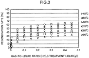
- FIGS. 2 and 3 illustrate regeneration rate (%) observed using an aqueous solution of an amine compound as the treatment liquid under varied regeneration temperatures.
- the treatment liquid was an aqueous solution containing 30% by mass of monoethanolamine (MEA) and 70% by mass of water.
- the absorption temperature was set to 40°C, and the partial pressure of carbon dioxide in the gas to be treated was 0.2 atm.
- Hydrogen gas was used as the separation promoting gas.
- Gas-to-liquid ratio was given by volume (liter) of the separation promoting gas per unit weight (1 g) of the treatment liquid.
- the cases with the separation promoting gas introduced therein were found to show improved regeneration rate of carbon dioxide, at any regeneration temperature.
- the regeneration rate can be improved by setting the regeneration temperature at high levels, and by setting the gas-to-liquid ratio again at high levels.
- Carbon dioxide could not be separated in the absence of the separation promoting gas unless the regeneration temperature was set to 70°C or above.
- introduction of the separation promoting could successfully release carbon oxide, even if the regeneration temperature was lowered down to 40°C, for example.
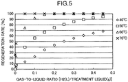
- FIGS. 4 and 5 illustrate results obtained from cases where the treatment liquid capable of causing phase separation upon absorption of carbon dioxide was used.
- the amine compound contained in the treatment liquid was 2-(ethylamino)ethanol (EAE), and the organic solvent was diethylene glycol diethyl ether (DEGDEE).
- the treatment liquid contained 30% by mass of EAE, 60% by mass of DEGDEE, and 10% by mass of water.
- the absorption temperature was set to 40°C, and the partial pressure of carbon dioxide in the gas to be treated was 0.2 atm. Hydrogen gas was used as the separation promoting gas.
- FIGS. 6 and 7 illustrate regeneration rate obtained from cases where both of the absorption temperature and the regeneration temperature were adjusted to 40°C, and the partial pressure of carbon dioxide in the gas to be treated was adjusted to 0.2 atm.
- the separation promoting gas was hydrogen gas.
- both substances were found to be not so largely different from each other when the gas-to-liquid ratio is small (at around 0.05), but the phase-separable treatment liquid improved the regeneration rate more largely than MEA did, when the gas-to-liquid ratio was large.
- the more the gas-to-liquid ratio increased the more the difference expanded.
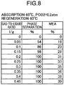
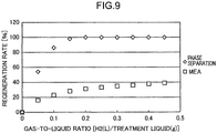
- Such tendency was observed, as illustrated in FIGS. 8 and 9 , also when the absorption temperature and the regeneration temperature were adjusted to 60°C.
- this embodiment brings, in the regeneration step, the separation promoting gas into contact with the treatment liquid.
- the regeneration temperature in the regenerator 14 may be set to a further lowered level, and this enables separation of the acidic compound at lower energy consumption.
- the regeneration step serves to separate carbon dioxide from the treatment liquid by not only bringing the separation promoting gas into contact with the treatment liquid, but also by presenting the acidic compound-deficient phase fraction. Hence, the energy required for regeneration of the treatment liquid may further be reduced.
- FIG. 10 illustrates a second embodiment of the present invention. All constituents same as those in the first embodiment will be given the same reference sings, and will not be detailed redundantly.
- the gas treatment apparatus 10 of the second embodiment includes heat transfer means (heat pump) 50 for transferring reaction heat generated in the absorber 12 to the regenerator 14.
- the heat transfer means 50 has a closed-loop circulation flow channel 50a having a coolant enclosed therein; and a compressor 50b, an evaporator 50c, an expansion mechanism 50d, a pump 50e and a condenser 50f, all of which being arranged on the circulation flow channel 50a.
- the evaporator 50c is typically composed of a heat transfer tube, and is arranged inside the absorber 12. In the absorber 12, an exothermic reaction occurs upon absorption of carbon dioxide by the treatment liquid.
- the coolant in the liquid state that flows through the evaporator 50c can evaporate upon being heated by the heat.
- the coolant in the gas state is compressed by the compressor 50b and flows into the condenser 50f.
- the condenser 50f is typically composed of a heat transfer tube, and is arranged inside the regenerator 14. In the regenerator 14, an endothermic reaction occurs upon release of carbon dioxide from the treatment liquid.
- the coolant in the gas state that flows through the condenser 50f is condensed by the endothermic reaction.
- the thus condensed liquid-state coolant is allowed to expand by the expansion mechanism 50d, transferred by the pump 50e, and fed into the evaporator 50c.
- the reaction heat generated in the absorber 12 is thus transferred to the regenerator 14, by means of circulation of the coolant.
- the second embodiment thus enables use of the reaction heat in the absorber 12 for regeneration of the treatment liquid, and can thereby further reduce energy required for regenerating the treatment liquid.
- the treatment liquid can be regenerated by adjusting the gas-to-liquid ratio to a high level, even if the regeneration temperature and the absorption temperature are almost comparable. With the gas-to-liquid ratio further elevated, the regeneration temperature can now be set lower than the absorption temperature. In this case, the reaction heat in the absorber 12 can be transferred to the regenerator 14, through direct heat exchange between the absorber 12 and the regenerator 14. The energy consumption rate in this process is given by 0 GJ/ton-CO2.
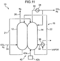
- the absorber 12 and the regenerator 14 are in direct contact with each other as illustrated in FIG. 11 .
- the wall face, over which the absorber 12 and the regenerator 14 come into contact can serve as a heat transfer surface.
- the reaction heat in the absorber 12 is transferred through this surface to the regenerator 14.
- Pressurizing inside the absorber 12 can further elevate the temperature of the treatment liquid in the absorber 12, and can thereby further effectively transfer the heat from the absorber 12 to the regenerator 14.
- the third embodiment enables use of the reaction heat in an absorber for regeneration of the treatment liquid, and can thereby further reduce energy required for regenerating the treatment liquid. Moreover, the embodiment no longer needs motive power for heat transfer unlike the heat pump, and can thereby further reduce the energy required for regeneration.
- FIG. 12 illustrates a fourth embodiment of the present invention.
- the fourth embodiment is similar to the third embodiment in that the absorber 12 and the regenerator 14 can exchange heat directly, except that the fourth embodiment employs a double-tube structure. That is, the regenerator 14 has a cylindrical shape, and the absorber 12 is arranged inside the cylinder. The outer circumferential surface of the absorber 12 and the inner circumferential surface of the regenerator 14 come into contact with each other to form a contact surface, which serves as a heat transfer surface. Now the absorber 12 may alternatively be formed in a cylindrical shape, with the regenerator 14 arranged inside the cylinder.
- the embodiment will be outlined.
Landscapes
- Chemical & Material Sciences (AREA)
- Engineering & Computer Science (AREA)
- Analytical Chemistry (AREA)
- General Chemical & Material Sciences (AREA)
- Oil, Petroleum & Natural Gas (AREA)
- Chemical Kinetics & Catalysis (AREA)
- Environmental & Geological Engineering (AREA)
- Health & Medical Sciences (AREA)
- Biomedical Technology (AREA)
- Life Sciences & Earth Sciences (AREA)
- Sustainable Development (AREA)
- Gas Separation By Absorption (AREA)
- Treating Waste Gases (AREA)
Abstract
Description
- The present invention relates to a gas treatment method and a gas treatment apparatus.
- A known gas treatment method brings a gas to be treated containing an acidic compound into contact with a treatment liquid, to separate the acidic compound. An exemplary gas treatment method disclosed in
Patent Literature 1 below employs a gas treatment apparatus having an absorber and a regenerator. The absorber brings the gas to be treated into contact with the treatment liquid, so as to make the treatment liquid absorb the acidic compound in the gas to be treated. The regenerator heats the treatment liquid, to thereby separate the acidic compound from the treatment liquid. - The conventional gas treatment method can recover carbon dioxide, by bringing, in the absorber, carbon dioxide into contact with the treatment liquid so as to be absorbed therein, and then by heating the treatment liquid in the regenerator. Energy required in this process typically amounts 4 GJ/ton-CO2. The present inventors have developed a technology for regenerating carbon dioxide at a temperature lower than before, by using an absorbent that can cause phase separation upon absorbing carbon dioxide. The present inventors have also confirmed that the energy could be reduced down to 1.5 GJ/ton-CO2 with combination of a heat-pump.
- With a growing interest on the global environment, awaited is a technology capable of separating and recovering the acidic compound with lesser energy consumption.
- Patent Literature 1:
JP 2011-213494 A - An object of the present invention is to reduce the energy required for separating and recovering the acidic compound.
- According to an aspect of the present invention, there is provide a gas treatment method including an absorption step in which a gas to be treated containing an acidic compound is brought into contact, in an absorber, with a treatment liquid absorbing the acidic compound, and a regeneration step in which the treatment liquid, having the acidic compound absorbed therein, is sent to a regenerator, and the treatment liquid is then heated to separate the acidic compound from the treatment liquid. In the regeneration step, a gas almost insoluble to the treatment liquid being fed to the regenerator, and the gas almost insoluble to the treatment liquid being then brought into contact with the treatment liquid.
- According to an aspect of the present invention, there is provide a gas treatment apparatus that uses a gas to be treated containing an acidic compound, and a treatment liquid for absorbing the acidic compound, to thereby separate the acidic compound from the gas to be treated, the gas treatment apparatus including an absorber configured to bring the treatment liquid into contact with the gas to be treated, a regenerator configured to heat the treatment liquid, having been brought into contact in the absorber with the gas to be treated, to thereby separate the acidic compound, and a gas feeding unit for feeding a gas almost insoluble to the treatment liquid to the regenerator.
-
-
FIG. 1 is a drawing schematically illustrating an overall structure of a gas treatment apparatus according to a first embodiment. -
FIG. 2 is a drawing illustrating a list of regeneration rate (%) observed using an aqueous MEA solution, under varied regeneration temperatures. -
FIG. 3 is a drawing illustrating variable plots of regeneration rate (%) observed using the aqueous MEA solution, under varied regeneration temperatures. -
FIG. 4 is a drawing illustrating a list of regeneration rate (%) observed using a treatment liquid capable of causing phase separation upon absorbing carbon dioxide, under varied regeneration temperatures. -
FIG. 5 is a drawing illustrating variable plots of regeneration rate (%) observed using the treatment liquid capable of causing phase separation upon absorbing carbon dioxide, under varied regeneration temperatures. -
FIG. 6 is a drawing illustrating a list of regeneration rate (%) observed using the phase-separable treatment liquid and the aqueous MEA solution, both at an absorption temperature and a regeneration temperature of 40°C. -
FIG. 7 is a drawing illustrating variable plots of regeneration rate (%) observed using the phase-separable treatment liquid and the aqueous MEA solution, both at an absorption temperature and a regeneration temperature of 40°C. -
FIG. 8 is a drawing illustrating a list of regeneration rate (%) observed using the phase-separable treatment liquid and the aqueous MEA solution, both at an absorption temperature and a regeneration temperature of 60°C. -
FIG. 9 is a drawing illustrating variable plots of regeneration rate (%) observed using the phase-separable treatment liquid and the aqueous MEA solution, both at an absorption temperature and a regeneration temperature of 60°C. -
FIG. 10 is a drawing schematically illustrating an overall structure of a gas treatment apparatus according to a second embodiment. -
FIG. 11 is a drawing schematically illustrating an overall structure of a gas treatment apparatus according to a third embodiment. -
FIG. 12 is a drawing schematically illustrating an overall structure of a gas treatment apparatus according to a fourth embodiment. - Embodiments of the present invention will now be described below referring to the attached drawings. Note that the embodiments below are provided merely for illustrative purposes of the present invention, and by no means limit the technical scope of the present invention.
- A
gas treatment apparatus 10 according to a first embodiment is used for separating an acidic compound from a gas to be treated containing the acidic compound, using a treatment liquid. Thegas treatment apparatus 10 has, as illustrated inFIG. 1 , anabsorber 12, aregenerator 14, acirculation channel 16, and aheat exchanger 18. Thecirculation channel 16 includes afirst flow channel 21 through which the treatment liquid drawn out from theabsorber 12 is fed into theregenerator 14, and asecond flow channel 22 through which the treatment liquid drawn out from theregenerator 14 is returned back to the absorption liquid. Theheat exchanger 18 is omissible. - The
absorber 12 has, connected thereto, afeed channel 24 through which the gas to be treated such as process gas is fed, agas discharge channel 26 through which a gas after processed is discharged, thefirst flow channel 21 through which the treatment liquid is fed to theregenerator 14, and asecond flow channel 22 through which the treatment liquid is returned from theregenerator 14 back into theabsorber 12. Thefeed channel 24 is connected to the bottom end of theabsorber 12. Thegas discharge channel 26 is connected to the top end of theabsorber 12. Thefirst flow channel 21 is connected to the bottom end or the vicinity of the bottom end of theabsorber 12. That is, thefirst flow channel 21 is connected to theabsorber 12 at a point where the treatment liquid pooled in theabsorber 12 can be drawn out. Thesecond flow channel 22 is connected to the top end or the vicinity of the top end of theabsorber 12. That is, thesecond flow channel 22 is connected to theabsorber 12 at a point where the treatment liquid returned from theregenerator 14 can fall from above. - In the
absorber 12, the gas to be treated and the treatment liquid are brought into contact, and thereby the acidic compound contained in the gas to be treated is separated from the gas to be treated and absorbed in the treatment liquid. After all, the gas freed from the acidic compound is discharged from theabsorber 12. This sort of absorber 12 may have any structure so long as it can bring the gas to be treated in to contact continuously with the treatment liquid, and may employ a reactor configured so as to spray the treatment liquid in the flow channel of the gas to be treated, configured so as to allow the treatment liquid to flow down through a filler arranged in the flow channel of the gas to be treated, or configured so as to introduce the gas to be treated and the treatment liquid individually into a large number of fine flow channels, and then combining such fine flow channels for the gas to be treated and the fine flow channels for the treatment liquid. Absorption of the acidic compound that takes place in theabsorber 12 is an exothermic reaction. Carbon dioxide, when representing the acidic compound, gives a calorific value of approximately 1.8 GJ per ton of absorption. The reaction heat generated in the absorber 12 elevates temperature of the gas to be treated and the treatment liquid. - The
regenerator 14 has, connected thereto, thefirst flow channel 21 and thesecond flow channel 22. Thefirst flow channel 21 is connected to top part of theregenerator 14, and allows the treatment liquid drawn out from theabsorber 12 to be fed into theregenerator 14. Thefirst flow channel 21 has apump 40 arranged thereto. Thesecond flow channel 22 is connected to the bottom end or the vicinity of the bottom end of theregenerator 14, and allows the treatment liquid pooled in theregenerator 14 to be drawn out. Thesecond flow channel 22 has apump 28 arranged thereto. - The
regenerator 14 pools the treatment liquid having the acidic compound absorbed therein. The pooled treatment liquid is heated in theregenerator 14 to release the acidic compound. Release of the acidic compound from the treatment liquid is an endothermic reaction. Upon heating of the treatment liquid in theregenerator 14, not only the acidic compound is released, but also water in the treatment liquid vaporizes. - The
regenerator 14 has connected thereto asupply channel 30 and aheating flow channel 32. Thesupply channel 30 feeds the acidic compound obtained in theregenerator 14 to a supply destination. Thesupply channel 30 has arranged thereto acondenser 34 that cools a mixed gas composed of a gas of the acidic compound vaporized from the treatment liquid and water vapor. Upon cooling of the mixed gas, the water vapor condenses. Thus the water vapor is separated through thecondenser 34. The thus separated water vapor is returned back to theregenerator 14. Thecondenser 34 may be composed of a heat exchanger that uses an inexpensive cooling water such as river water. - One end of the
heating flow channel 32, connected to thesecond flow channel 22, may alternatively be connected to the bottom end or the vicinity of the bottom end of theregenerator 14. The other end of theheating flow channel 32 is connected to the lower part of theregenerator 14. - The
heating flow channel 32 has arranged thereto areboiler 36 that heats the treatment liquid pooled in theregenerator 14. Although thereboiler 36 may be arranged inside theregenerator 14 so as to heat the treatment liquid, it may alternatively be configured as illustrated in the drawing so as to heat the treatment liquid drawn outside theregenerator 14. Thereboiler 36 in this case may be arranged to theheating flow channel 32 for returning to theregenerator 14 after heating. Thereboiler 36 employable here may be any of those capable of directly or indirectly heating the treatment liquid, with a freely selectable heat source using electricity, vapor, burner or the like. - The
heat exchanger 18 is connected to thefirst flow channel 21 and thesecond flow channel 22, enabling heat exchange between the treatment liquid that flows through thefirst flow channel 21 and the treatment liquid that flows through thesecond flow channel 22. Theheat exchanger 18 is typically composed of a plate heat exchanger, but not limited thereto. Theheat exchanger 18 may be composed of a micro-channel heat exchanger capable of causing heat exchange between fluids having a relatively small difference of temperature. This successfully improves energy efficiency. - The
gas treatment apparatus 10 has agas feeding unit 42 that feeds a gas for promoting separation of the acidic compound (referred to as "separation promoting gas", hereinafter) to theregenerator 14. Thegas feeding unit 42 has agas channel 42a connected to the bottom end or the vicinity of the bottom end of theregenerator 14. Thegas channel 42a is typically connected to asupply source 42b of the separation promoting gas. - The separation promoting gas, fed from the
gas feeding unit 42 to theregenerator 14, is a gas almost insoluble to the treatment liquid. The separation promoting gas is exemplified by hydrogen gas, oxygen gas, and methane gas. With the gas almost insoluble to the treatment liquid fed to theregenerator 14, separation of the acidic compound in theregenerator 14 is promoted. Now "almost insoluble" to the treatment liquid may represent that the solubility in the treatment liquid is not larger than a predetermined value. The separation promoting gas will suffice if it conforms to Henry's law, and has a solubility of 1 mol or smaller in 100 g of the treatment liquid at 0°C and under 100 kPa. Oxygen has a solubility of 1.3 × 10⁻⁴ mol/100 g in water, methane has a solubility of 8×10⁴ mol/100 g in water, and hydrogen has a solubility of 9.5 × 10⁻⁵ mol/100 g in water. In contrast, ammonia having a solubility of 6 mol/100 g in water does not fall under such gas. - The acidic compound to be separated by the
gas treatment apparatus 10 is not specifically limited so long as the aqueous solution thereof becomes acidic, and is exemplified by hydrogen chloride, carbon dioxide, sulfur dioxide, and carbon disulfide. The gas to be treated containing the acidic compound is exemplified by industrial effluent gas, natural gas and hydrogen gas. That is, thegas treatment apparatus 10 of this embodiment is applicable for the purpose of removing hazardous substances from gases emitted to the atmosphere, or for the purpose of removing impurities from gases used typically as fuel. - This embodiment employs, as the treatment liquid (absorbent) used for the
gas treatment apparatus 10, an absorbent capable of reversibly absorbing and releasing the acidic compound. The treatment liquid is an alkaline absorbent typically containing water, an amine compound, and an organic solvent. The amine compound may account for 30 wt%, the organic solvent for 60 wt%, and water for 10 wt%. The treatment liquid preferably causes phase separation upon absorbing the acidic compound that produces an acid when dissolved in water, but is not limited thereto. The treatment liquid may typically be an aqueous solution of an amine compound, free of organic solvent. Again alternatively, the treatment liquid may be an amine compound, organic solvent, ionic liquid, or mixture or aqueous solution of these compounds. - The amine compound is exemplified by primary amines such as 1,3-diaminopropane (DAP: solubility parameter = 14.6 (cal/cm3)1/2), 2-aminoethanol (MEA: solubility parameter = 14.3 (cal/cm3)1/2), DL-2-amino-1-propanol (AP: solubility parameter = 13.3 (cal/cm3)1/2), 2-(2-aminoethoxy)ethanol (AEE: solubility parameter = 12.7 (cal/cm3)1/2), and (R)-4-amino-2-methyl-1-butanol (AMB); secondary amines such as 2-(methylamino)ethanol (MAE), 2-(ethylamino)ethanol (EAE), and 2-(butylamino)ethanol (BAE); and tertiary amines such as triethanolamine (TEA), N-methyldiethanolamine (MDEA), tetramethylethylene diamine (TEMED), pentamethyldiethylene triamine (PMDETA), hexamethyltriethylene tetramine, and bis(2-dimethylaminoethyl) ether.
- The organic solvent is exemplified by 1-butanol (solubility parameter = 11.3(cal/cm3)1/2), 1-pentanol (solubility parameter = 11.0(cal/cm3)1/2), octanol, diethylene glycol diethyl ether (DEGDEE), and diethylene glycol dimethyl ether (DEGDME). Two or more kinds of them may be used in a combined manner.
- If each of the amine compound and the organic solvent has the solubility parameter within a predetermined range, the treatment liquid upon absorbing the acidic compound will be separated into an acidic compound-rich phase and an acidic compound-deficient phase. The solubility parameter is given by equation (1) below.
- [Math. 1]

- ΔH represents molar latent heat of vaporization, R represents the gas constant, T represents absolute temperature, and V represents molar volume. The solubility parameter of EAE and MAE as the amine compounds, and DEGDME as the organic solvent, calculated using equation (1) are found to be 10.94, 11.58 and 7.75, respectively.

- As summarized in Table 1, the treatment liquid separates, upon absorbing the acidic compound, into the acidic compound-rich phase and the acidic compound-deficient phase, when the absorbent (treatment liquid) containing water, amine compound and organic solvent, is based on a combination of the amine compound and the organic solvent, properly selected so as to give a difference, remained after subtracting the solubility parameter of the organic solvent from the solubility parameter of the amine compound, of 1.1 (cal/cm3)1/2 or larger and 4.2 (cal/cm3)1/2 or smaller. If the solubility parameter is smaller than the lower limit value, the treatment liquid would not separate into two phases, upon absorbing the acidic compound. Meanwhile, if the solubility parameter exceeds the upper limit value, the treatment liquid would separate into two phases, before absorbing the acidic compound. This would destabilize uniform contact between the treatment liquid and the gas to be treated containing the acidic compound, in the process where the treatment liquid is brought into contact with the gas to be treated containing the acidic compound, and would degrade the absorption efficiency. "Good" in Table 1 means that the treatment liquid remains in a single liquid phase before absorbing carbon dioxide, and separates into two phases upon absorbing carbon dioxide. "Not mixed" in Table 1 means that the treatment liquid remained in two liquid phases before absorbing carbon dioxide, and did not form a single liquid phase. "Not separated" in Table 1 means that the treatment liquid remained in a single liquid phase, even after absorbing carbon dioxide.
- Absorption conditions in the
absorber 12 are preferably adjusted so as to make the treatment liquid remain in two liquid phases and can dissolve therein much carbon dioxide, and regeneration conditions in theregenerator 14 are preferably adjusted so as to make the treatment liquid inseparable into two liquid phases, and can dissolve therein less carbon dioxide. That is, the absorption and regeneration conditions are adjusted, depending on partial pressure of carbon dioxide, absorption temperature and regeneration temperature. This makes the treatment liquid more easily cause phase separation, and can thereby reduce difference between the regeneration temperature and the absorption temperature. In other words, the invention makes use of shift of concentration equilibrium of carbon dioxide absorption, caused by changes in the degree of absorption of carbon dioxide depending on temperature, and consequently by changes in easiness of phase separation. Hence, it becomes possible to suppress the difference between the regeneration temperature and the absorption temperature to a low level. In addition, with the gas hardly soluble to the treatment liquid fed into theregenerator 14, the difference between the regeneration temperature and the absorption temperature may further be narrowed. - Now a gas treatment method, using the
gas treatment apparatus 10 of the first embodiment, will be described. The gas treatment method includes an absorption step, a liquid transfer step, and a regeneration step. - The absorption step is a step bringing, in the
absorber 12, the gas to be treated into contact with the treatment liquid. To theabsorber 12, there is fed the gas to be treated such as a process gas that contains at least carbon dioxide, through thefeed channel 24. To theabsorber 12, there is fed the absorption liquid, through thesecond flow channel 22 of thecirculation channel 16. The absorption liquid flows down inside theabsorber 12, comes into contact with carbon dioxide contained in the gas to be treated, and absorbs carbon dioxide. Theabsorber 12 thus pools the treatment liquid having absorbed carbon dioxide. In a case where the phase-separable treatment liquid is used, the treatment liquid having come into contact with the carbon dioxide is then separated into a first phase fraction with a high carbon dioxide content, and a second phase fraction with a low carbon dioxide content. The processed gas after being separated from carbon dioxide is discharged through thegas discharge channel 26 out of theabsorber 12. - The liquid transfer step is a step for transferring the treatment liquid, pooled in the
absorber 12, from theabsorber 12 to theregenerator 14. In the liquid transfer step, the whole amount of the treatment liquid, output from theabsorber 12, is introduced into theregenerator 14. The treatment liquid that flows through thefirst flow channel 21 in this process is heated in theheat exchanger 18 by the treatment liquid that flows through thesecond flow channel 22, and then introduced into theregenerator 14. By virtue of thepump 40 arranged to thefirst flow channel 21, the treatment liquid, even if kept in a phase-separated state in theabsorber 12, may occasionally be introduced into theregenerator 14 with the first phase fraction and the second phase fraction mixed with each other. - The regeneration step is a step for separating carbon dioxide from the treatment liquid, by heating the treatment liquid introduced into the
regenerator 14. In theregenerator 14, the treatment liquid is heated while flowing down. Meanwhile, the separation promoting gas, fed from thesupply source 42b through thegas channel 42a into theregenerator 14, flows up inside theregenerator 14 and comes into contact with the treatment liquid. That is, in the regeneration step, the treatment liquid and the separation promoting gas flow in opposing directions to come into contact with each other. Since the treatment liquid in theregenerator 14 is heated in the presence of the separation promoting gas, so that the regeneration temperature of the carbon dioxide may be suppressed to a low level. The treatment liquid heated in theregenerator 14 may occasionally vaporize to generate water vapor. Carbon dioxide and the water vapor, separated from the treatment liquid, flow through thesupply channel 30. While passing through thesupply channel 30, the water vapor is condensed by thecondenser 34, and returned back to theregenerator 14. Only carbon dioxide, separated from the treatment liquid, is thus fed to a supply destination. The treatment liquid pooled in theregenerator 14 flows through thesecond flow channel 22 back into theabsorber 12. During this process, the treatment liquid gives heat, in theheat exchanger 18, to the treatment liquid that flows through thefirst flow channel 21, to thereby cool down in itself. - Having confirmed that the separation promoting gas, fed into the
regenerator 14, successfully improved the regeneration rate of carbon dioxide, now this point will further be described.FIGS. 2 and3 illustrate regeneration rate (%) observed using an aqueous solution of an amine compound as the treatment liquid under varied regeneration temperatures. The treatment liquid was an aqueous solution containing 30% by mass of monoethanolamine (MEA) and 70% by mass of water. The absorption temperature was set to 40°C, and the partial pressure of carbon dioxide in the gas to be treated was 0.2 atm. Hydrogen gas was used as the separation promoting gas. Gas-to-liquid ratio was given by volume (liter) of the separation promoting gas per unit weight (1 g) of the treatment liquid. - As compared with the case free of the separation promoting gas (gas-to-liquid ratio = 0), the cases with the separation promoting gas introduced therein were found to show improved regeneration rate of carbon dioxide, at any regeneration temperature. The regeneration rate can be improved by setting the regeneration temperature at high levels, and by setting the gas-to-liquid ratio again at high levels. Carbon dioxide could not be separated in the absence of the separation promoting gas unless the regeneration temperature was set to 70°C or above. Now, introduction of the separation promoting could successfully release carbon oxide, even if the regeneration temperature was lowered down to 40°C, for example.
-
FIGS. 4 and5 illustrate results obtained from cases where the treatment liquid capable of causing phase separation upon absorption of carbon dioxide was used. The amine compound contained in the treatment liquid was 2-(ethylamino)ethanol (EAE), and the organic solvent was diethylene glycol diethyl ether (DEGDEE). The treatment liquid contained 30% by mass of EAE, 60% by mass of DEGDEE, and 10% by mass of water. The absorption temperature was set to 40°C, and the partial pressure of carbon dioxide in the gas to be treated was 0.2 atm. Hydrogen gas was used as the separation promoting gas. - Even in the phase-separable treatment liquid, as with the MEA, as compared with the case free of the separation promoting gas (gas-to-liquid ratio = 0), the cases with the separation promoting gas introduced therein were found to show improved regeneration rate of carbon dioxide, at any regeneration temperature. Moreover, the regeneration rate can be improved by setting the regeneration temperature at high levels, and by setting the gas-to-liquid ratio again at high levels. A regeneration rate of 100% was found to be achieved even at a regeneration temperature of 60°C, by adjusting the gas-to-liquid ratio to 0.2 or larger. Hence, use of the phase-separable treatment liquid can improve the regeneration rate, and can lower the regeneration temperature.
- Next paragraphs will deal with comparison between the phase-separable treatment liquid and MEA.
FIGS. 6 and7 illustrate regeneration rate obtained from cases where both of the absorption temperature and the regeneration temperature were adjusted to 40°C, and the partial pressure of carbon dioxide in the gas to be treated was adjusted to 0.2 atm. The separation promoting gas was hydrogen gas. As known fromFIGS. 6 and7 , both substances were found to be not so largely different from each other when the gas-to-liquid ratio is small (at around 0.05), but the phase-separable treatment liquid improved the regeneration rate more largely than MEA did, when the gas-to-liquid ratio was large. Moreover, the more the gas-to-liquid ratio increased, the more the difference expanded. Such tendency was observed, as illustrated inFIGS. 8 and9 , also when the absorption temperature and the regeneration temperature were adjusted to 60°C. - As described above, this embodiment brings, in the regeneration step, the separation promoting gas into contact with the treatment liquid. This makes the acidic compound, dissolved in the treatment liquid, more easily separable from the treatment liquid, and what is better, the separated acidic compound is purged from the treatment liquid, while being entrained with the gas. Separation of the acidic compound from the treatment liquid is thus promoted. Hence, the regeneration temperature in the
regenerator 14 may be set to a further lowered level, and this enables separation of the acidic compound at lower energy consumption. - In a case where the treatment liquid capable of causing phase separation upon absorbing carbon dioxide is used, the regeneration step serves to separate carbon dioxide from the treatment liquid by not only bringing the separation promoting gas into contact with the treatment liquid, but also by presenting the acidic compound-deficient phase fraction. Hence, the energy required for regeneration of the treatment liquid may further be reduced.
-
FIG. 10 illustrates a second embodiment of the present invention. All constituents same as those in the first embodiment will be given the same reference sings, and will not be detailed redundantly. - The
gas treatment apparatus 10 of the second embodiment includes heat transfer means (heat pump) 50 for transferring reaction heat generated in theabsorber 12 to theregenerator 14. The heat transfer means 50 has a closed-loopcirculation flow channel 50a having a coolant enclosed therein; and acompressor 50b, an evaporator 50c, anexpansion mechanism 50d, apump 50e and acondenser 50f, all of which being arranged on thecirculation flow channel 50a. The evaporator 50c is typically composed of a heat transfer tube, and is arranged inside theabsorber 12. In theabsorber 12, an exothermic reaction occurs upon absorption of carbon dioxide by the treatment liquid. The coolant in the liquid state that flows through the evaporator 50c can evaporate upon being heated by the heat. The coolant in the gas state is compressed by thecompressor 50b and flows into thecondenser 50f. Thecondenser 50f is typically composed of a heat transfer tube, and is arranged inside theregenerator 14. In theregenerator 14, an endothermic reaction occurs upon release of carbon dioxide from the treatment liquid. The coolant in the gas state that flows through thecondenser 50f is condensed by the endothermic reaction. The thus condensed liquid-state coolant is allowed to expand by theexpansion mechanism 50d, transferred by thepump 50e, and fed into the evaporator 50c. The reaction heat generated in theabsorber 12 is thus transferred to theregenerator 14, by means of circulation of the coolant. - The second embodiment thus enables use of the reaction heat in the
absorber 12 for regeneration of the treatment liquid, and can thereby further reduce energy required for regenerating the treatment liquid. - All other structures, operations and effects, although will not be described here, are same as those in the first embodiment.
- As described in the first embodiment, the treatment liquid can be regenerated by adjusting the gas-to-liquid ratio to a high level, even if the regeneration temperature and the absorption temperature are almost comparable. With the gas-to-liquid ratio further elevated, the regeneration temperature can now be set lower than the absorption temperature. In this case, the reaction heat in the
absorber 12 can be transferred to theregenerator 14, through direct heat exchange between theabsorber 12 and theregenerator 14. The energy consumption rate in this process is given by 0 GJ/ton-CO2. - The
absorber 12 and theregenerator 14 are in direct contact with each other as illustrated inFIG. 11 . Hence, the wall face, over which theabsorber 12 and theregenerator 14 come into contact, can serve as a heat transfer surface. The reaction heat in theabsorber 12 is transferred through this surface to theregenerator 14. Pressurizing inside theabsorber 12 can further elevate the temperature of the treatment liquid in theabsorber 12, and can thereby further effectively transfer the heat from theabsorber 12 to theregenerator 14. - The third embodiment enables use of the reaction heat in an absorber for regeneration of the treatment liquid, and can thereby further reduce energy required for regenerating the treatment liquid. Moreover, the embodiment no longer needs motive power for heat transfer unlike the heat pump, and can thereby further reduce the energy required for regeneration.
- All other structures, operations and effects, although will not be described here, are same as those in the first embodiment.
-
FIG. 12 illustrates a fourth embodiment of the present invention. The fourth embodiment is similar to the third embodiment in that theabsorber 12 and theregenerator 14 can exchange heat directly, except that the fourth embodiment employs a double-tube structure. That is, theregenerator 14 has a cylindrical shape, and theabsorber 12 is arranged inside the cylinder. The outer circumferential surface of theabsorber 12 and the inner circumferential surface of theregenerator 14 come into contact with each other to form a contact surface, which serves as a heat transfer surface. Now theabsorber 12 may alternatively be formed in a cylindrical shape, with theregenerator 14 arranged inside the cylinder. - All other structures, operations and effects, although will not be described here, are same as those in the third embodiment.
- The embodiment will be outlined.
- (1) According to the above embodiment, there is provided a gas treatment method including an absorption step in which a gas to be treated containing an acidic compound is brought into contact, in an absorber, with a treatment liquid for absorbing the acidic compound, and a regeneration step in which the treatment liquid, having the acidic compound absorbed therein, is sent to a regenerator, and the treatment liquid is then heated to separate the acidic compound from the treatment liquid. In the regeneration step, a gas almost insoluble to the treatment liquid is fed to the regenerator, and the gas almost insoluble to the treatment liquid is then brought into contact with the treatment liquid.
In the regeneration step of the embodiment, the gas almost insoluble to the treatment liquid is brought into contact with the treatment liquid. This makes the acidic compound, dissolved in the treatment liquid, more easily separable from the treatment liquid, and what is better, the separated acidic compound is purged from the treatment liquid, while being entrained with the gas. Separation of the acidic compound from the treatment liquid is thus promoted. Hence, the regeneration temperature in the regenerator may be set to a further lowered level, and this enables separation of the acidic compound at lower energy consumption. - (2) The gas treatment method may use heat transfer means for transferring reaction heat, generated in the absorber, to the regenerator. This embodiment enables use of the reaction heat in an absorber for regeneration of the treatment liquid, and can thereby further reduce energy required for regenerating the treatment liquid.
- (3) In the gas treatment method, the absorber and the regenerator may exchange heat directly. By increasing the feed volume of the gas almost insoluble to the treatment liquid to the regenerator, it now becomes possible to equalize the temperatures of the absorber and the regenerator, or to set the temperature of the regenerator lower than the temperature of the absorber. This enables direct exchange of the reaction heat generated in the absorber to the regenerator. This enables use of the reaction heat in the absorber for regeneration of the treatment liquid without using the power of a pump or the like, and can thereby further reduce energy required for regenerating the treatment liquid.
- (4) In the gas treatment method, difference of temperature of the absorber from temperature of the regenerator may fall in a range from -20°C to 30°C.
- (5) In the gas treatment method, in the regeneration step, 0.05 liters or more of the gas, per 1 g of the treatment liquid, may be fed to the regenerator. This embodiment can exert an effect of promoting separation of the acidic compound from the treatment liquid in a more efficient manner.
- (6) In the gas treatment method, the treatment liquid may cause phase separation, upon absorbing the acidic compound, into phases with different content proportions of the acidic compound. This embodiment separates the acidic compound from the treatment liquid in the regenerating step, not only by bringing the gas, almost insoluble to the treatment liquid, into contact with the treatment liquid, but also by allowing the acidic compound-deficient phase fraction to coexist. Hence, the energy required for regeneration of the treatment liquid may further be reduced.
- (7) According to the above embodiment, there is provided a gas treatment apparatus that uses a gas to be treated containing an acidic compound, and a treatment liquid for absorbing the acidic compound, to thereby separate the acidic compound from the gas to be treated, the gas treatment apparatus including an absorber configured to bring the treatment liquid into contact with the gas to be treated, a regenerator configured to heat the treatment liquid, having been brought into contact in the absorber with the gas to be treated, to thereby separate the acidic compound, and a gas feeding unit for feeding a gas almost insoluble to the treatment liquid to the regenerator.
- (8) The gas treatment apparatus may further include means for transferring reaction heat generated in the absorber to the regenerator.
- (9) In the gas treatment apparatus, the absorber and the regenerator may be configured to exchange heat directly.
- (10) In the gas treatment apparatus, difference of temperature of the absorber from temperature of the regenerator may fall in a range from -20°C to 30°C.
- (11) In the gas treatment apparatus, the gas feeding unit may feed 0.05 liters or more of the gas, per 1 g of the treatment liquid, to the regenerator.
- (12) In the gas treatment apparatus, the treatment liquid may cause phase separation, upon absorbing the acidic compound, into phases with different content proportions of the acidic compound.
- As described above, in the above-described embodiment, it is possible to reduce the energy required for separating and recovering the acidic compound.
Claims (12)
- A gas treatment method comprising:an absorption step in which a gas to be treated containing an acidic compound is brought into contact, in an absorber, with a treatment liquid for absorbing the acidic compound; anda regeneration step in which the treatment liquid, having the acidic compound absorbed therein, is sent to a regenerator, and the treatment liquid is then heated to separate the acidic compound from the treatment liquid,wherein in the regeneration step, a gas almost insoluble to the treatment liquid is fed to the regenerator, and the gas almost insoluble to the treatment liquid is then brought into contact with the treatment liquid.
- The gas treatment method according to claim 1, wherein heat transfer means for transferring reaction heat, generated in the absorber, to the regenerator is used.
- The gas treatment method according to claim 1, wherein the absorber and the regenerator exchange heat directly.
- The gas treatment method according to any one of claims 1 to 3, wherein difference of temperature of the absorber from temperature of the regenerator falls in a range from -20°C to 30°C.
- The gas treatment method according to any one of claims 1 to 3, wherein in the regeneration step, 0.05 liters or more of the gas, per 1 g of the treatment liquid, is fed to the regenerator.
- The gas treatment method according to any one of claims 1 to 3, wherein the treatment liquid causes phase separation, upon absorbing the acidic compound, into phases with different content proportions of the acidic compound.
- A gas treatment apparatus that uses a gas to be treated containing an acidic compound, and a treatment liquid for absorbing the acidic compound, to thereby separate the acidic compound from the gas to be treated,
the gas treatment apparatus comprising:an absorber configured to bring the treatment liquid into contact with the gas to be treated;a regenerator configured to heat the treatment liquid, having been brought into contact in the absorber with the gas to be treated, to thereby separate the acidic compound; anda gas feeding unit for feeding a gas almost insoluble to the treatment liquid to the regenerator. - The gas treatment apparatus according to claim 7, further comprising means for transferring reaction heat generated in the absorber to the regenerator.
- The gas treatment apparatus according to claim 7, wherein the absorber and the regenerator are configured to exchange heat directly.
- The gas treatment apparatus according to any one of claims 7 to 9, wherein difference of temperature of the absorber from temperature of the regenerator falls in a range from -20°C to 30°C.
- The gas treatment apparatus according to any one of claims 7 to 9, wherein the gas feeding unit feeds 0.05 liters or more of the gas, per 1 g of the treatment liquid, to the regenerator.
- The gas treatment apparatus according to any one of claims 7 to 9, wherein the treatment liquid causes phase separation, upon absorbing the acidic compound, into phases with different content proportions of the acidic compound.
Applications Claiming Priority (2)
| Application Number | Priority Date | Filing Date | Title |
|---|---|---|---|
| JP2017229936A JP6906766B2 (en) | 2017-11-30 | 2017-11-30 | Gas treatment method and gas treatment equipment |
| PCT/JP2018/041882 WO2019107136A1 (en) | 2017-11-30 | 2018-11-12 | Gas treatment method and gas treatment apparatus |
Publications (3)
| Publication Number | Publication Date |
|---|---|
| EP3702015A1 true EP3702015A1 (en) | 2020-09-02 |
| EP3702015A4 EP3702015A4 (en) | 2021-04-28 |
| EP3702015B1 EP3702015B1 (en) | 2024-01-10 |
Family
ID=66665660
Family Applications (1)
| Application Number | Title | Priority Date | Filing Date |
|---|---|---|---|
| EP18882476.7A Active EP3702015B1 (en) | 2017-11-30 | 2018-11-12 | Gas treatment method and gas treatment apparatus |
Country Status (5)
| Country | Link |
|---|---|
| US (1) | US11331625B2 (en) |
| EP (1) | EP3702015B1 (en) |
| JP (1) | JP6906766B2 (en) |
| CN (1) | CN111372671B (en) |
| WO (1) | WO2019107136A1 (en) |
Families Citing this family (14)
| Publication number | Priority date | Publication date | Assignee | Title |
|---|---|---|---|---|
| FR3099710B1 (en) * | 2019-08-08 | 2021-08-06 | Ifp Energies Now | Absorption gas treatment process using thermally optimized hot flash solvent regeneration |
| EP4041436A1 (en) * | 2019-10-11 | 2022-08-17 | thyssenkrupp Industrial Solutions AG | Exhaust gas scrubber with energy integration |
| JP7517650B2 (en) * | 2020-01-29 | 2024-07-17 | 株式会社神戸製鋼所 | Gas Treatment Equipment |
| JP2021130633A (en) * | 2020-02-20 | 2021-09-09 | 株式会社タクマ | Methane manufacturing method, methanol manufacturing method, methane manufacturing facility and methanol manufacturing facility |
| CN112705013B (en) * | 2020-12-25 | 2023-04-07 | 临沭县华盛化工有限公司 | Process for absorbing hydrogen chloride gas by 'double-serial-parallel' alcohol |
| JP2024521040A (en) * | 2021-05-07 | 2024-05-28 | エネルケム インコーポレイティド | Optimizing carbon monoxide production from heterogeneous feedstocks. |
| JP7802581B2 (en) * | 2022-03-16 | 2026-01-20 | 三菱重工業株式会社 | Carbon dioxide capture system |
| JP7813009B2 (en) * | 2022-08-09 | 2026-02-12 | 株式会社神戸製鋼所 | Gas treatment device and gas treatment method |
| JP2024115206A (en) * | 2023-02-14 | 2024-08-26 | 株式会社神戸製鋼所 | Gas processing method and gas processing device |
| JPWO2025004800A1 (en) | 2023-06-29 | 2025-01-02 | ||
| EP4736988A1 (en) | 2023-06-29 | 2026-05-06 | Agc Inc. | Acidic gas-absorbing liquid and acidic gas reduction method |
| JP2025008548A (en) * | 2023-07-05 | 2025-01-20 | 株式会社神戸製鋼所 | Gas treatment device and gas treatment method |
| JP2025062825A (en) * | 2023-10-03 | 2025-04-15 | 株式会社神戸製鋼所 | Gas treatment device and gas treatment method |
| JP2026109980A (en) * | 2024-12-20 | 2026-07-02 | 株式会社神戸製鋼所 | Gas separation apparatus and gas separation method |
Family Cites Families (25)
| Publication number | Priority date | Publication date | Assignee | Title |
|---|---|---|---|---|
| AU501376B2 (en) * | 1976-02-23 | 1979-06-21 | Dow Chemical Company, The | Liquid desiccants and absorbants when acid gases are present or mixtures thereof |
| JPS5344651U (en) * | 1976-09-22 | 1978-04-17 | ||
| JPS5849222B2 (en) | 1976-09-30 | 1983-11-02 | 鐘淵化学工業株式会社 | Gluten fiber manufacturing method |
| US4198378A (en) * | 1976-11-12 | 1980-04-15 | Giuseppe Giammarco | Process for removing CO2, H2 S and other gaseous impurities from gaseous mixtures |
| DE4014018A1 (en) | 1990-05-01 | 1991-11-07 | Metallgesellschaft Ag | Gas purificn. using recyclable scrubber soln. - esp. for desulphurisation of fuel gas |
| CN1137753C (en) * | 2000-12-19 | 2004-02-11 | 中国冶金建设集团鞍山焦化耐火材料设计研究总院 | Process for removing CO2 and H2S from biological gas |
| US7597746B2 (en) * | 2002-12-17 | 2009-10-06 | Fluor Technologies Corporation | Configurations and methods for acid gas and contaminant removal with near zero emission |
| US7056482B2 (en) * | 2003-06-12 | 2006-06-06 | Cansolv Technologies Inc. | Method for recovery of CO2 from gas streams |
| FR2898284B1 (en) * | 2006-03-10 | 2009-06-05 | Inst Francais Du Petrole | METHOD FOR DEACIDIFYING GAS BY ABSORBENT SOLUTION WITH HEATED FRACTIONAL REGENERATION. |
| AU2008281856B2 (en) * | 2007-07-31 | 2011-06-30 | Shell Internationale Research Maatschappij B.V. | Process for producing purified gas from gas comprising H2S, CO2 and HCN and/or COS |
| PL2300128T3 (en) | 2008-06-23 | 2014-01-31 | Basf Se | Absorption medium and method for removing sour gases from fluid streams, in particular from flue gases |
| PL2300127T3 (en) * | 2008-06-23 | 2015-08-31 | Basf Se | Absorption medium and method for removing sour gases from fluid streams, in particular from flue gases |
| CA2761895C (en) | 2009-05-26 | 2018-08-28 | Basf Se | Process for recovery of carbon dioxide from a fluid stream, in particular from syngas |
| JP5641194B2 (en) * | 2010-03-31 | 2014-12-17 | 新日鉄住金エンジニアリング株式会社 | Carbon dioxide gas recovery device |
| DE102011108749A1 (en) * | 2011-07-28 | 2013-01-31 | Thyssenkrupp Uhde Gmbh | Heat recovery in absorption and desorption processes |
| MX2014005746A (en) * | 2011-11-14 | 2014-07-09 | Evonik Degussa Gmbh | Method and device for the separation of acidic gases from a gas mixture. |
| WO2013114936A1 (en) | 2012-02-01 | 2013-08-08 | 国立大学法人 東京大学 | Distillation device and distillation method |
| JP6173817B2 (en) * | 2013-07-30 | 2017-08-02 | 株式会社東芝 | Acid gas absorbent, acid gas removal method, and acid gas removal apparatus |
| CN103756734B (en) * | 2014-01-16 | 2015-03-04 | 中石化宁波工程有限公司 | Energy-saving low-temperature methanol-washing H2S concentration process |
| CN106457125B (en) * | 2014-05-23 | 2019-03-26 | 塔明克公司 | Improved method for acid gas removal by absorbent solutions containing amine compounds |
| CA2959093C (en) * | 2014-08-25 | 2022-11-22 | Basf Se | Removal of hydrogen sulphide and carbon dioxide from a stream of fluid |
| EP3067108A1 (en) * | 2015-03-11 | 2016-09-14 | Nederlandse Organisatie voor toegepast- natuurwetenschappelijk onderzoek TNO | Acid gas removal with an absorption liquid that separates in two liquid phases |
| CN106422667B (en) | 2015-08-04 | 2019-07-30 | 北京思践通科技发展有限公司 | The method of one-step removal acidic components and water from gas |
| JP6656843B2 (en) * | 2015-08-21 | 2020-03-04 | 株式会社神戸製鋼所 | Gas processing system and gas processing method |
| CN106474871B (en) * | 2016-11-09 | 2019-01-11 | 中石化宁波工程有限公司 | The sour gas of mating coal water slurry gasification reabsorbs technique |
-
2017
- 2017-11-30 JP JP2017229936A patent/JP6906766B2/en active Active
-
2018
- 2018-11-12 EP EP18882476.7A patent/EP3702015B1/en active Active
- 2018-11-12 CN CN201880075687.1A patent/CN111372671B/en active Active
- 2018-11-12 WO PCT/JP2018/041882 patent/WO2019107136A1/en not_active Ceased
- 2018-11-12 US US16/766,915 patent/US11331625B2/en active Active
Also Published As
| Publication number | Publication date |
|---|---|
| JP2019098226A (en) | 2019-06-24 |
| EP3702015B1 (en) | 2024-01-10 |
| US20210016226A1 (en) | 2021-01-21 |
| CN111372671A (en) | 2020-07-03 |
| EP3702015A4 (en) | 2021-04-28 |
| WO2019107136A1 (en) | 2019-06-06 |
| US11331625B2 (en) | 2022-05-17 |
| JP6906766B2 (en) | 2021-07-21 |
| CN111372671B (en) | 2022-05-31 |
Similar Documents
| Publication | Publication Date | Title |
|---|---|---|
| EP3702015B1 (en) | Gas treatment method and gas treatment apparatus | |
| US11185814B2 (en) | Absorption agent, method of manufacturing same, and method for separation and recovery of acidic compound | |
| US11400410B2 (en) | Compositions and methods for carbon dioxide capture | |
| CN104338417B (en) | Carbon dioxide separating and capturing system and method of operating same | |
| CN108786380B (en) | Gas processing method and gas processing device | |
| JP2009521314A (en) | Reuse of amines for carbon dioxide recovery | |
| GB2516153A (en) | Carbon dioxide recovery system and method of operating the carbon dioxide recovery system | |
| JP2017035669A (en) | Acid gas absorbent, acid gas removal method, and acid gas removal apparatus | |
| EP4548999A1 (en) | Gas treatment apparatus and gas treatment method | |
| AU2021356435B2 (en) | Gas-treating device | |
| WO2024171649A1 (en) | Gas treatment method and gas treatment device | |
| US11433351B2 (en) | System and method of recovering carbon dioxide from a stream of gas | |
| EP4741042A1 (en) | Gas treatment apparatus and gas treatment method | |
| US12383861B2 (en) | Gas treatment method, and gas treatment device |
Legal Events
| Date | Code | Title | Description |
|---|---|---|---|
| STAA | Information on the status of an ep patent application or granted ep patent |
Free format text: STATUS: THE INTERNATIONAL PUBLICATION HAS BEEN MADE |
|
| PUAI | Public reference made under article 153(3) epc to a published international application that has entered the european phase |
Free format text: ORIGINAL CODE: 0009012 |
|
| STAA | Information on the status of an ep patent application or granted ep patent |
Free format text: STATUS: REQUEST FOR EXAMINATION WAS MADE |
|
| 17P | Request for examination filed |
Effective date: 20200526 |
|
| AK | Designated contracting states |
Kind code of ref document: A1 Designated state(s): AL AT BE BG CH CY CZ DE DK EE ES FI FR GB GR HR HU IE IS IT LI LT LU LV MC MK MT NL NO PL PT RO RS SE SI SK SM TR |
|
| AX | Request for extension of the european patent |
Extension state: BA ME |
|
| DAV | Request for validation of the european patent (deleted) | ||
| DAX | Request for extension of the european patent (deleted) | ||
| A4 | Supplementary search report drawn up and despatched |
Effective date: 20210329 |
|
| RIC1 | Information provided on ipc code assigned before grant |
Ipc: B01D 53/14 20060101AFI20210323BHEP Ipc: B01D 53/62 20060101ALI20210323BHEP Ipc: B01D 53/78 20060101ALI20210323BHEP Ipc: B01D 53/96 20060101ALI20210323BHEP |
|
| STAA | Information on the status of an ep patent application or granted ep patent |
Free format text: STATUS: EXAMINATION IS IN PROGRESS |
|
| 17Q | First examination report despatched |
Effective date: 20220727 |
|
| GRAP | Despatch of communication of intention to grant a patent |
Free format text: ORIGINAL CODE: EPIDOSNIGR1 |
|
| STAA | Information on the status of an ep patent application or granted ep patent |
Free format text: STATUS: GRANT OF PATENT IS INTENDED |
|
| INTG | Intention to grant announced |
Effective date: 20230822 |
|
| GRAS | Grant fee paid |
Free format text: ORIGINAL CODE: EPIDOSNIGR3 |
|
| P01 | Opt-out of the competence of the unified patent court (upc) registered |
Effective date: 20231031 |
|
| GRAA | (expected) grant |
Free format text: ORIGINAL CODE: 0009210 |
|
| STAA | Information on the status of an ep patent application or granted ep patent |
Free format text: STATUS: THE PATENT HAS BEEN GRANTED |
|
| AK | Designated contracting states |
Kind code of ref document: B1 Designated state(s): AL AT BE BG CH CY CZ DE DK EE ES FI FR GB GR HR HU IE IS IT LI LT LU LV MC MK MT NL NO PL PT RO RS SE SI SK SM TR |
|
| REG | Reference to a national code |
Ref country code: GB Ref legal event code: FG4D |
|
| REG | Reference to a national code |
Ref country code: CH Ref legal event code: EP |
|
| REG | Reference to a national code |
Ref country code: DE Ref legal event code: R096 Ref document number: 602018064107 Country of ref document: DE |
|
| REG | Reference to a national code |
Ref country code: IE Ref legal event code: FG4D |
|
| REG | Reference to a national code |
Ref country code: NL Ref legal event code: FP |
|
| REG | Reference to a national code |
Ref country code: SE Ref legal event code: TRGR |
|
| REG | Reference to a national code |
Ref country code: LT Ref legal event code: MG9D |
|
| REG | Reference to a national code |
Ref country code: AT Ref legal event code: MK05 Ref document number: 1648469 Country of ref document: AT Kind code of ref document: T Effective date: 20240110 |
|
| PG25 | Lapsed in a contracting state [announced via postgrant information from national office to epo] |
Ref country code: IS Free format text: LAPSE BECAUSE OF FAILURE TO SUBMIT A TRANSLATION OF THE DESCRIPTION OR TO PAY THE FEE WITHIN THE PRESCRIBED TIME-LIMIT Effective date: 20240510 |
|
| PG25 | Lapsed in a contracting state [announced via postgrant information from national office to epo] |
Ref country code: LT Free format text: LAPSE BECAUSE OF FAILURE TO SUBMIT A TRANSLATION OF THE DESCRIPTION OR TO PAY THE FEE WITHIN THE PRESCRIBED TIME-LIMIT Effective date: 20240110 |
|
| PG25 | Lapsed in a contracting state [announced via postgrant information from national office to epo] |
Ref country code: GR Free format text: LAPSE BECAUSE OF FAILURE TO SUBMIT A TRANSLATION OF THE DESCRIPTION OR TO PAY THE FEE WITHIN THE PRESCRIBED TIME-LIMIT Effective date: 20240411 |
|
| PG25 | Lapsed in a contracting state [announced via postgrant information from national office to epo] |
Ref country code: RS Free format text: LAPSE BECAUSE OF FAILURE TO SUBMIT A TRANSLATION OF THE DESCRIPTION OR TO PAY THE FEE WITHIN THE PRESCRIBED TIME-LIMIT Effective date: 20240410 Ref country code: HR Free format text: LAPSE BECAUSE OF FAILURE TO SUBMIT A TRANSLATION OF THE DESCRIPTION OR TO PAY THE FEE WITHIN THE PRESCRIBED TIME-LIMIT Effective date: 20240110 |
|
| PG25 | Lapsed in a contracting state [announced via postgrant information from national office to epo] |
Ref country code: ES Free format text: LAPSE BECAUSE OF FAILURE TO SUBMIT A TRANSLATION OF THE DESCRIPTION OR TO PAY THE FEE WITHIN THE PRESCRIBED TIME-LIMIT Effective date: 20240110 |
|
| PG25 | Lapsed in a contracting state [announced via postgrant information from national office to epo] |
Ref country code: AT Free format text: LAPSE BECAUSE OF FAILURE TO SUBMIT A TRANSLATION OF THE DESCRIPTION OR TO PAY THE FEE WITHIN THE PRESCRIBED TIME-LIMIT Effective date: 20240110 |
|
| PG25 | Lapsed in a contracting state [announced via postgrant information from national office to epo] |
Ref country code: RS Free format text: LAPSE BECAUSE OF FAILURE TO SUBMIT A TRANSLATION OF THE DESCRIPTION OR TO PAY THE FEE WITHIN THE PRESCRIBED TIME-LIMIT Effective date: 20240410 Ref country code: LT Free format text: LAPSE BECAUSE OF FAILURE TO SUBMIT A TRANSLATION OF THE DESCRIPTION OR TO PAY THE FEE WITHIN THE PRESCRIBED TIME-LIMIT Effective date: 20240110 Ref country code: IS Free format text: LAPSE BECAUSE OF FAILURE TO SUBMIT A TRANSLATION OF THE DESCRIPTION OR TO PAY THE FEE WITHIN THE PRESCRIBED TIME-LIMIT Effective date: 20240510 Ref country code: HR Free format text: LAPSE BECAUSE OF FAILURE TO SUBMIT A TRANSLATION OF THE DESCRIPTION OR TO PAY THE FEE WITHIN THE PRESCRIBED TIME-LIMIT Effective date: 20240110 Ref country code: GR Free format text: LAPSE BECAUSE OF FAILURE TO SUBMIT A TRANSLATION OF THE DESCRIPTION OR TO PAY THE FEE WITHIN THE PRESCRIBED TIME-LIMIT Effective date: 20240411 Ref country code: ES Free format text: LAPSE BECAUSE OF FAILURE TO SUBMIT A TRANSLATION OF THE DESCRIPTION OR TO PAY THE FEE WITHIN THE PRESCRIBED TIME-LIMIT Effective date: 20240110 Ref country code: BG Free format text: LAPSE BECAUSE OF FAILURE TO SUBMIT A TRANSLATION OF THE DESCRIPTION OR TO PAY THE FEE WITHIN THE PRESCRIBED TIME-LIMIT Effective date: 20240110 Ref country code: AT Free format text: LAPSE BECAUSE OF FAILURE TO SUBMIT A TRANSLATION OF THE DESCRIPTION OR TO PAY THE FEE WITHIN THE PRESCRIBED TIME-LIMIT Effective date: 20240110 |
|
| PG25 | Lapsed in a contracting state [announced via postgrant information from national office to epo] |
Ref country code: PT Free format text: LAPSE BECAUSE OF FAILURE TO SUBMIT A TRANSLATION OF THE DESCRIPTION OR TO PAY THE FEE WITHIN THE PRESCRIBED TIME-LIMIT Effective date: 20240510 Ref country code: PL Free format text: LAPSE BECAUSE OF FAILURE TO SUBMIT A TRANSLATION OF THE DESCRIPTION OR TO PAY THE FEE WITHIN THE PRESCRIBED TIME-LIMIT Effective date: 20240110 |
|
| PG25 | Lapsed in a contracting state [announced via postgrant information from national office to epo] |
Ref country code: PT Free format text: LAPSE BECAUSE OF FAILURE TO SUBMIT A TRANSLATION OF THE DESCRIPTION OR TO PAY THE FEE WITHIN THE PRESCRIBED TIME-LIMIT Effective date: 20240510 Ref country code: PL Free format text: LAPSE BECAUSE OF FAILURE TO SUBMIT A TRANSLATION OF THE DESCRIPTION OR TO PAY THE FEE WITHIN THE PRESCRIBED TIME-LIMIT Effective date: 20240110 Ref country code: LV Free format text: LAPSE BECAUSE OF FAILURE TO SUBMIT A TRANSLATION OF THE DESCRIPTION OR TO PAY THE FEE WITHIN THE PRESCRIBED TIME-LIMIT Effective date: 20240110 |
|
| PG25 | Lapsed in a contracting state [announced via postgrant information from national office to epo] |
Ref country code: DK Free format text: LAPSE BECAUSE OF FAILURE TO SUBMIT A TRANSLATION OF THE DESCRIPTION OR TO PAY THE FEE WITHIN THE PRESCRIBED TIME-LIMIT Effective date: 20240110 |
|
| REG | Reference to a national code |
Ref country code: DE Ref legal event code: R097 Ref document number: 602018064107 Country of ref document: DE |
|
| PG25 | Lapsed in a contracting state [announced via postgrant information from national office to epo] |
Ref country code: SM Free format text: LAPSE BECAUSE OF FAILURE TO SUBMIT A TRANSLATION OF THE DESCRIPTION OR TO PAY THE FEE WITHIN THE PRESCRIBED TIME-LIMIT Effective date: 20240110 |
|
| PG25 | Lapsed in a contracting state [announced via postgrant information from national office to epo] |
Ref country code: CZ Free format text: LAPSE BECAUSE OF FAILURE TO SUBMIT A TRANSLATION OF THE DESCRIPTION OR TO PAY THE FEE WITHIN THE PRESCRIBED TIME-LIMIT Effective date: 20240110 Ref country code: EE Free format text: LAPSE BECAUSE OF FAILURE TO SUBMIT A TRANSLATION OF THE DESCRIPTION OR TO PAY THE FEE WITHIN THE PRESCRIBED TIME-LIMIT Effective date: 20240110 |
|
| PG25 | Lapsed in a contracting state [announced via postgrant information from national office to epo] |
Ref country code: SK Free format text: LAPSE BECAUSE OF FAILURE TO SUBMIT A TRANSLATION OF THE DESCRIPTION OR TO PAY THE FEE WITHIN THE PRESCRIBED TIME-LIMIT Effective date: 20240110 |
|
| PG25 | Lapsed in a contracting state [announced via postgrant information from national office to epo] |
Ref country code: SM Free format text: LAPSE BECAUSE OF FAILURE TO SUBMIT A TRANSLATION OF THE DESCRIPTION OR TO PAY THE FEE WITHIN THE PRESCRIBED TIME-LIMIT Effective date: 20240110 Ref country code: SK Free format text: LAPSE BECAUSE OF FAILURE TO SUBMIT A TRANSLATION OF THE DESCRIPTION OR TO PAY THE FEE WITHIN THE PRESCRIBED TIME-LIMIT Effective date: 20240110 Ref country code: RO Free format text: LAPSE BECAUSE OF FAILURE TO SUBMIT A TRANSLATION OF THE DESCRIPTION OR TO PAY THE FEE WITHIN THE PRESCRIBED TIME-LIMIT Effective date: 20240110 Ref country code: EE Free format text: LAPSE BECAUSE OF FAILURE TO SUBMIT A TRANSLATION OF THE DESCRIPTION OR TO PAY THE FEE WITHIN THE PRESCRIBED TIME-LIMIT Effective date: 20240110 Ref country code: DK Free format text: LAPSE BECAUSE OF FAILURE TO SUBMIT A TRANSLATION OF THE DESCRIPTION OR TO PAY THE FEE WITHIN THE PRESCRIBED TIME-LIMIT Effective date: 20240110 Ref country code: CZ Free format text: LAPSE BECAUSE OF FAILURE TO SUBMIT A TRANSLATION OF THE DESCRIPTION OR TO PAY THE FEE WITHIN THE PRESCRIBED TIME-LIMIT Effective date: 20240110 |
|
| PLBE | No opposition filed within time limit |
Free format text: ORIGINAL CODE: 0009261 |
|
| STAA | Information on the status of an ep patent application or granted ep patent |
Free format text: STATUS: NO OPPOSITION FILED WITHIN TIME LIMIT |
|
| PG25 | Lapsed in a contracting state [announced via postgrant information from national office to epo] |
Ref country code: IT Free format text: LAPSE BECAUSE OF FAILURE TO SUBMIT A TRANSLATION OF THE DESCRIPTION OR TO PAY THE FEE WITHIN THE PRESCRIBED TIME-LIMIT Effective date: 20240110 |
|
| 26N | No opposition filed |
Effective date: 20241011 |
|
| PG25 | Lapsed in a contracting state [announced via postgrant information from national office to epo] |
Ref country code: IT Free format text: LAPSE BECAUSE OF FAILURE TO SUBMIT A TRANSLATION OF THE DESCRIPTION OR TO PAY THE FEE WITHIN THE PRESCRIBED TIME-LIMIT Effective date: 20240110 |
|
| PG25 | Lapsed in a contracting state [announced via postgrant information from national office to epo] |
Ref country code: SI Free format text: LAPSE BECAUSE OF FAILURE TO SUBMIT A TRANSLATION OF THE DESCRIPTION OR TO PAY THE FEE WITHIN THE PRESCRIBED TIME-LIMIT Effective date: 20240110 |
|
| REG | Reference to a national code |
Ref country code: CH Ref legal event code: PL |
|
| PG25 | Lapsed in a contracting state [announced via postgrant information from national office to epo] |
Ref country code: MC Free format text: LAPSE BECAUSE OF FAILURE TO SUBMIT A TRANSLATION OF THE DESCRIPTION OR TO PAY THE FEE WITHIN THE PRESCRIBED TIME-LIMIT Effective date: 20240110 |
|
| PG25 | Lapsed in a contracting state [announced via postgrant information from national office to epo] |
Ref country code: LU Free format text: LAPSE BECAUSE OF NON-PAYMENT OF DUE FEES Effective date: 20241112 |
|
| REG | Reference to a national code |
Ref country code: CH Ref legal event code: PL |
|
| PG25 | Lapsed in a contracting state [announced via postgrant information from national office to epo] |
Ref country code: CH Free format text: LAPSE BECAUSE OF NON-PAYMENT OF DUE FEES Effective date: 20241130 |
|
| REG | Reference to a national code |
Ref country code: BE Ref legal event code: MM Effective date: 20241130 |
|
| PG25 | Lapsed in a contracting state [announced via postgrant information from national office to epo] |
Ref country code: FI Free format text: LAPSE BECAUSE OF FAILURE TO SUBMIT A TRANSLATION OF THE DESCRIPTION OR TO PAY THE FEE WITHIN THE PRESCRIBED TIME-LIMIT Effective date: 20240110 |
|
| PG25 | Lapsed in a contracting state [announced via postgrant information from national office to epo] |
Ref country code: BE Free format text: LAPSE BECAUSE OF NON-PAYMENT OF DUE FEES Effective date: 20241130 |
|
| PG25 | Lapsed in a contracting state [announced via postgrant information from national office to epo] |
Ref country code: FR Free format text: LAPSE BECAUSE OF NON-PAYMENT OF DUE FEES Effective date: 20241130 |
|
| PG25 | Lapsed in a contracting state [announced via postgrant information from national office to epo] |
Ref country code: IE Free format text: LAPSE BECAUSE OF NON-PAYMENT OF DUE FEES Effective date: 20241112 |
|
| PGFP | Annual fee paid to national office [announced via postgrant information from national office to epo] |
Ref country code: NL Payment date: 20251003 Year of fee payment: 8 |
|
| PGFP | Annual fee paid to national office [announced via postgrant information from national office to epo] |
Ref country code: DE Payment date: 20250930 Year of fee payment: 8 |
|
| PGFP | Annual fee paid to national office [announced via postgrant information from national office to epo] |
Ref country code: GB Payment date: 20251001 Year of fee payment: 8 |
|
| PGFP | Annual fee paid to national office [announced via postgrant information from national office to epo] |
Ref country code: NO Payment date: 20251113 Year of fee payment: 8 |
|
| PGFP | Annual fee paid to national office [announced via postgrant information from national office to epo] |
Ref country code: SE Payment date: 20251001 Year of fee payment: 8 |
|
| PG25 | Lapsed in a contracting state [announced via postgrant information from national office to epo] |
Ref country code: HU Free format text: LAPSE BECAUSE OF FAILURE TO SUBMIT A TRANSLATION OF THE DESCRIPTION OR TO PAY THE FEE WITHIN THE PRESCRIBED TIME-LIMIT; INVALID AB INITIO Effective date: 20181112 |
|
| PG25 | Lapsed in a contracting state [announced via postgrant information from national office to epo] |
Ref country code: CY Free format text: LAPSE BECAUSE OF FAILURE TO SUBMIT A TRANSLATION OF THE DESCRIPTION OR TO PAY THE FEE WITHIN THE PRESCRIBED TIME-LIMIT; INVALID AB INITIO Effective date: 20181112 |
|
| PG25 | Lapsed in a contracting state [announced via postgrant information from national office to epo] |
Ref country code: TR Free format text: LAPSE BECAUSE OF FAILURE TO SUBMIT A TRANSLATION OF THE DESCRIPTION OR TO PAY THE FEE WITHIN THE PRESCRIBED TIME-LIMIT Effective date: 20240110 |