EP3701829B1 - Applicator for hair - Google Patents
Applicator for hair Download PDFInfo
- Publication number
- EP3701829B1 EP3701829B1 EP18870514.9A EP18870514A EP3701829B1 EP 3701829 B1 EP3701829 B1 EP 3701829B1 EP 18870514 A EP18870514 A EP 18870514A EP 3701829 B1 EP3701829 B1 EP 3701829B1
- Authority
- EP
- European Patent Office
- Prior art keywords
- comb
- hair
- applying part
- view
- barrel
- Prior art date
- Legal status (The legal status is an assumption and is not a legal conclusion. Google has not performed a legal analysis and makes no representation as to the accuracy of the status listed.)
- Active
Links
- 239000011248 coating agent Substances 0.000 claims description 17
- 238000000576 coating method Methods 0.000 claims description 17
- 239000011148 porous material Substances 0.000 claims description 8
- 239000000118 hair dye Substances 0.000 claims description 7
- 230000000052 comparative effect Effects 0.000 description 14
- 238000010586 diagram Methods 0.000 description 11
- 230000002745 absorbent Effects 0.000 description 10
- 239000002250 absorbent Substances 0.000 description 10
- 239000004744 fabric Substances 0.000 description 10
- 239000007788 liquid Substances 0.000 description 9
- 239000002537 cosmetic Substances 0.000 description 5
- 238000000034 method Methods 0.000 description 4
- 238000012360 testing method Methods 0.000 description 4
- 238000005259 measurement Methods 0.000 description 3
- 238000000465 moulding Methods 0.000 description 3
- LFQSCWFLJHTTHZ-UHFFFAOYSA-N Ethanol Chemical compound CCO LFQSCWFLJHTTHZ-UHFFFAOYSA-N 0.000 description 2
- 241001465754 Metazoa Species 0.000 description 2
- 238000006073 displacement reaction Methods 0.000 description 2
- 239000012530 fluid Substances 0.000 description 2
- 230000006870 function Effects 0.000 description 2
- 230000008595 infiltration Effects 0.000 description 2
- 238000001764 infiltration Methods 0.000 description 2
- 230000002093 peripheral effect Effects 0.000 description 2
- 238000010186 staining Methods 0.000 description 2
- 238000012546 transfer Methods 0.000 description 2
- 241000283707 Capra Species 0.000 description 1
- 230000015572 biosynthetic process Effects 0.000 description 1
- 239000003795 chemical substances by application Substances 0.000 description 1
- 210000001520 comb Anatomy 0.000 description 1
- 230000007423 decrease Effects 0.000 description 1
- 238000001035 drying Methods 0.000 description 1
- 238000004043 dyeing Methods 0.000 description 1
- 230000000694 effects Effects 0.000 description 1
- 238000011156 evaluation Methods 0.000 description 1
- 238000001125 extrusion Methods 0.000 description 1
- 238000011049 filling Methods 0.000 description 1
- 238000000227 grinding Methods 0.000 description 1
- 238000011835 investigation Methods 0.000 description 1
- 238000004519 manufacturing process Methods 0.000 description 1
- 239000000463 material Substances 0.000 description 1
- 230000000149 penetrating effect Effects 0.000 description 1
- 239000012466 permeate Substances 0.000 description 1
- 238000002360 preparation method Methods 0.000 description 1
- 239000000047 product Substances 0.000 description 1
- 230000035807 sensation Effects 0.000 description 1
- 238000010998 test method Methods 0.000 description 1
- 230000007306 turnover Effects 0.000 description 1
Images


Classifications
-
- A—HUMAN NECESSITIES
- A45—HAND OR TRAVELLING ARTICLES
- A45D—HAIRDRESSING OR SHAVING EQUIPMENT; EQUIPMENT FOR COSMETICS OR COSMETIC TREATMENTS, e.g. FOR MANICURING OR PEDICURING
- A45D34/00—Containers or accessories specially adapted for handling liquid toiletry or cosmetic substances, e.g. perfumes
- A45D34/04—Appliances specially adapted for applying liquid, e.g. using roller or ball
- A45D34/042—Appliances specially adapted for applying liquid, e.g. using roller or ball using a brush or the like
-
- A—HUMAN NECESSITIES
- A45—HAND OR TRAVELLING ARTICLES
- A45D—HAIRDRESSING OR SHAVING EQUIPMENT; EQUIPMENT FOR COSMETICS OR COSMETIC TREATMENTS, e.g. FOR MANICURING OR PEDICURING
- A45D19/00—Devices for washing the hair or the scalp; Similar devices for colouring the hair
- A45D19/02—Hand-actuated implements, e.g. hand-actuated spray heads
- A45D19/026—Hand-actuated implements, e.g. hand-actuated spray heads having brush or comb applicators
-
- A—HUMAN NECESSITIES
- A45—HAND OR TRAVELLING ARTICLES
- A45D—HAIRDRESSING OR SHAVING EQUIPMENT; EQUIPMENT FOR COSMETICS OR COSMETIC TREATMENTS, e.g. FOR MANICURING OR PEDICURING
- A45D24/00—Hair combs for care of the hair; Accessories therefor
- A45D24/22—Combs with dispensing devices for liquids, pastes or powders
- A45D24/24—Combs with dispensing devices for liquids, pastes or powders with provision for free supply; using wicks
-
- A—HUMAN NECESSITIES
- A45—HAND OR TRAVELLING ARTICLES
- A45D—HAIRDRESSING OR SHAVING EQUIPMENT; EQUIPMENT FOR COSMETICS OR COSMETIC TREATMENTS, e.g. FOR MANICURING OR PEDICURING
- A45D24/00—Hair combs for care of the hair; Accessories therefor
- A45D24/22—Combs with dispensing devices for liquids, pastes or powders
- A45D24/26—Combs with dispensing devices for liquids, pastes or powders with flexible walls of the liquid, paste, or powder storing device
-
- A—HUMAN NECESSITIES
- A45—HAND OR TRAVELLING ARTICLES
- A45D—HAIRDRESSING OR SHAVING EQUIPMENT; EQUIPMENT FOR COSMETICS OR COSMETIC TREATMENTS, e.g. FOR MANICURING OR PEDICURING
- A45D2200/00—Details not otherwise provided for in A45D
- A45D2200/10—Details of applicators
- A45D2200/1009—Applicators comprising a pad, tissue, sponge, or the like
Definitions
- the present invention relates to a hair applicator for applying a hair cosmetic such as a hair dye, which is attached to a container body to apply an application liquid (hair dye, hair styling agent, hair restorer, etc.) stored in the container, to hair (hair including humans and other pet animals) while combing the hair.
- a hair cosmetic such as a hair dye
- an application liquid hair dye, hair styling agent, hair restorer, etc.
- Patent Documents 1 to 4 disclose hair applicators which have a structure including a combing body joined with an applying part of a porous material such as a sponge to apply and infiltrate the application liquid to the hair while combing with the combing body.
- Patent Documents 1 to 4 have the following problems.
- the combing body is fixed by provision of a bridge to prevent the porous applying part from falling off.
- the spacing between the comb elements is wide, the tips of the comb elements easily sink into the skin, so that the applying part easily touches and stains the skin. If a large clearance is secured between the combing body and the applying part in order to prevent the skin from being stained, there occurs a problem that the strength of contact of the applying part against the hair is weakened, so that the coating amount decreases.
- a non-infiltration member is integrally molded around the applying part (cosmetic penetrating member) to prevent the skin from being stained due to displacement of the applying part.
- the molding method is limited to extrusion molding, so that the manufacturing method and configuration lose flexibility.
- this method is easily expected to raise the costs required for, for example, the integral molding of the non-infiltration member and the grinding process after the integral molding.
- the present invention has been devised in view of the above circumstances, it is therefore an object of the present invention to provide a hair applicator which can fix an applying part to a comb with a sufficient fixing strength to prevent the applying part from being displaced even by an impact from a fall and also can dispense a sufficient coating amount.
- the present invention resides in a hair applicator according to claim 1.
- the applying part can be secured to the comb with a sufficient securing strength, so that it possible to prevent the applying part from being displaced even by an impact from a fall and obtain a sufficient coating amount.
- FIGS. 1 to 6 are illustrative diagrams showing a hair applicator according to the first embodiment.
- the hair applicator includes an applying part 10 of a porous material and a comb 12 having comb elements 12a, formed with the applying part 10.
- the hair applicator is an applicator for hair that can dispense a hair dye in the front barrel (corresponding to the "container") 14 from the applying part 10 to the hair when the comb 12 combs the hair.
- the hair applicator has a cap 16 detachably attached to a front end part 14a of the front barrel 14 so as to cover the applying part 10.
- the cap 16 prevents the applying part 10 from drying by putting an inner cap 16a in hermetic contact with the outer peripheral side of the front end part 14a of the front barrel 14.
- the front barrel 14 has a substantially hollow cylindrical shape with the front end part 14a formed in a spatulate flat appearance having an opening forward of the hollow.
- the comb 12 is formed in the front end part 14a so as to surround the opening, and the applying part 10 is exposed from the opening.
- a tail plug (lid) 18 is fitted to the rear end of the front barrel 14 to close the hollow inside the front barrel 14 so as to provide a container function.
- an absorbent fabric 20 is stuffed in the closed space in the front barrel 14, and impregnated with the hair dye.
- the applying part 10 is arranged inside the comb 12 of the front barrel 14.
- the rear end of applying part 10 is inserted into the front portion of the absorbent fabric 20, so that the hair dye of the absorbent fabric 20 permeates the applying part 10.
- the front barrel 14 is covered from the center to the rear with a rear barrel 22.
- the rear barrel 22 has a cylindrical shape with a closed rear end, and a rib 22a for preventing rotation of the front barrel 14 is formed on the inner periphery along the axial direction.
- the rib 22a is formed as a projected portion such as a parallel rail.
- the front barrel 14 has a recess 14i formed along the axial direction on the outer surface in the rear portion thereof (see FIG. 3 ).
- the recess 14i of the front barrel 14 mates with the locking rib 22a to prevent the front barrel 14 from rotating with respect to the rear barrel 22.
- the front barrel 14 has a male thread 14b on the outer peripheral side of the front end part 14a for the cap 16 to be screwed thereon.
- a flange 14c is formed on the outer periphery adjacent to the rear of the male screw 14b.
- a fitting rib 14d is formed behind the flange 14c on the outer periphery.
- the rear barrel 22 has an annular projected portion 22b on the inner surface in the front part thereof.
- projected portions 14e are formed inside the front end part 14a of the front barrel 14 to catch a step portion 10c of the applying part.
- the applying part 10 is formed of a porous material having a porosity of 80% or higher and a hardness under ISO7619A of less than A70, which dispenses a coating amount of 0.090 g/m or greater
- the applying part 10 is given in the form of a flat plate having a greater width relative to the thickness.
- the applying part 10 is formed of a front portion (applying tip side) 10a of a width W1 and a rear portion 10b of a width W2 smaller than W1, forming a substantially T-shape.
- the applying part 10 uses felt as the porous material in the embodiment.
- the dimensions of the applying part 10 are such that the thickness t is about 7 to 2 (mm), the width W1 of the front portion 10a is wider than the width W2 of the rear part 10b (W1> W2), and a step 10c is formed at the boundary between the front portion 10a and the rear portion 10b.
- the width W1 can be 15 to 10 (mm) and the width W2 can be 13 to 8 (mm).
- the length of the front portion 10a can be 15 to 10 (mm) and the length of the rear portion 10b can be 13 to 8 (mm) .
- the rear endface of the rear portion 10b contacts the absorbent fabric 20, but can be made flat.
- the front portion 10a of the width W1 serving as the applying tip is fitted inside of the front end part 14a. Further, the step 10c located at the boundary to the rear portion 10b of the width W2 is locked by the projected portions 14e formed in the front end part 14a of the front barrel 14. Therefore, this locking prevents the applying part 10 from sliding backward into the absorbent fabric 20 in the front barrel 14.
- a plurality of comb elements 12a extending forward are formed integrally with the front end part 14a of the front barrel 14.
- the front end part 14a has a rectangular opening, and holds the applying part 10 therein.
- the front end part 14a is configured such that the applying part 10 is held by the comb 12 on the front side with the tips of the comb elements 12a project forward beyond the front end of the applying part 10.
- beams 12b for anti-falling are formed so as to connect the opposing comb elements 12a.
- the step 10c abuts against the projected portions 14e inside the front barrel 14 (the front end part 14a) in the interior of the comb 12 to prevent the applying part 10 from moving rearward.
- the applying part 10 is made of a felt or the like that is softer than the applying part that is press-fitted in the conventional front barrel (Patent Document 1 and Patent Document 4), the applying part 10 is positioned and fixed on the front side by the beams 12b, and on the rear side by the projected portions 14e, so that the applying part 10 will not be displaced.
- the beam 12b between the comb elements 12a has a hollow 12b1 formed on the surface thereof. Further, the surface area of the tip of the comb element 12a is specified to be 0.3 to 1.0 mm 2 .
- the coating amount is 0.090 g/m or greater and the porous material has a porosity of 80% or higher and a hardness under ISO7619A of less than A70, the hardness is sufficient, so that it is possible to prevent the applying part from coming off from the front end part 14a of the front barrel 14.
- the applying part can be fixed to the comb elements with a sufficient fixing force, and prevented from being displaced even by an impact from a fall while an ample coating amount can be secured.
- the beams 12b are provided between the comb elements 12a of the front end part 14a, as described above. As shown in detail in FIGS. 2 and 5 , the beams 12b provide a stopper function for the applying part 10.
- an evaluation test was performed on the applying part 10 that was specified so that the coating amount was 0.090 g/m or greater and the porous material had a porosity of 80% or higher and a hardness under ISO7619A of less than A70.
- Example 1 the applying parts of Examples 1 and 2 of the present invention were felt cores, and the coating amount was 0.115 (g) in Example 1 and 0.104 (g) in Example 2.
- Comparative Examples 1 and 2 were felt cores, and the coating amount was 0.079 (g) in Comparative Example 1 and 0.069 (g) in Comparative Example 2.
- the porosity of each of Examples 1 and 2 and Comparative Examples 1 and 2 is an actual measurement value, which was obtained as the volume converted from the full filling weight of ethanol.
- the hardness is also an actual measurement value, which was obtained by using a rubber hardness meter (conforming to ISO7619A).
- each coating amount was 0.115 (g) in Example 1 and 0.104 (g) in Example 2, whereas the coating amount was 0.079 (g) in Comparative Example 1, and coating amount of Comparative Example 2 was 0.069 (g) .
- the applicators of Examples 1 and 2 have a coating amount of 10 to 12 times or more that of the applicators of Comparative Examples 1 and 2. Thus, according to the present invention, it has become clear that a markedly sufficient amount of coating (approximately an order of magnitude greater) can be applied to the hair.
- FIG. 5 shows a comparative example, and (b) shows a variational example 1.
- the comb 12 of the front barrel 14 has its front end located ahead of the applying part, if the front end of the comb 12 is formed flat as in the comparative example shown in FIG. 5(a) , the fluid may adhere to the skin.
- the cosmetic (application liquid) applied to the hair transfers to the flat top surface of the comb 12 and the top surface touches the skin so that the hair cosmetic is transferred to adhere to and stain the skin.
- the hollow 12b1 is formed on the front endface of the beam 12b of the comb 12 to reduce the contact area between the skin and the comb 12, so that transfer of the liquid can be avoided.
- FIG. 6 shows a comparative example, and (b) and (c) show the front barrel of the first embodiment.
- the cosmetic is more likely to adhere to the skin than in the conventional product. That is, as the comb elements 12a of the comb 12 are reduced in number, the contact area is reduced, hence it became easier to sink into the skin, and the applying part 10 easily comes into direct contact with the skin.
- the comb 12 in the comparative example shown in FIG. 6A has two pairs of comb elements 12a
- the comb 12 of the first embodiment shown in FIGS. 6B and 6C has five pairs of comb elements 12a so as to suppress sinking into the skin and make staining the skin unlikely.
- the beam 12b is provided in every other pair of the comb elements 12a among the five pairs in the comb 12, and hollows 12b1 are also formed.
- the area of the flat part in the front end of the comb part 12 was 0.4 mm 2
- the gap between the comb elements 12a was 1.3 mm.
- the step height of the hollow 12b1 in the preferred comb 12 was found to be 0.5 to 0.9 mm.
- FIGS. 7 to 10 are illustrative diagrams of a hair applicator according to a second embodiment
- FIG. 10 is an illustrative view of an applying part.
- the hair applicator according to the first embodiment is configured such that the comb elements 12a of the comb 12 are arranged and formed in the direction perpendicular to the center axis of the front barrel 14.
- the comb elements 12a of the comb 12 are arranged and formed in an inclined manner at an angle ⁇ with respect to the center axis of the front barrel 14 (indicated by the symbol "C" in FIG. 8 ).
- the applying part 10 is slanted forming a front part 10a of the facet inclined at the angle ⁇ with respect to the center axis (indicated by the symbol "C" in FIG. 10 ) .
- the applicator can be obliquely applied to the hair unlike the first embodiment in which the applicator is applied vertically. It is hence suitable for application to the hairline and the like. Others are the same as in the first embodiment.
- FIGS. 11 and 12 are illustrative diagrams of the hair applicator according to the third embodiment.
- FIG. 13 is an illustrative diagram of a front barrel
- FIG. 14 is an illustrative diagram of an applying part.
- the same parts as those in the first embodiment shown in FIGS. 1 to 4 are denoted by the same reference numerals.
- the applying part 10 and the absorbent fabric 20 are the same as those in the first embodiment, and those in the second embodiment can also be adopted.
- the third embodiment is different from the first and second embodiments in the configurations other than the applying part 10 and the absorbent fabric 20.
- a container for accommodating the absorbent fabric 20 is formed with the rear end of the front barrel 14 closed by a tail plug 18.
- the tail plug 18 abuts the inner surface 22c (bottom surface) at the rear end of the rear barrel 22.
- the front part of the tail plug 18 serves as a part closing the rear end of the front barrel 14.
- the rear end of the tail plug 18 that is greater in diameter than the front end thereof serves as a part closing the rear end of the rear barrel 22.
- the hair applicator also has a cap 16 that covers the applying part 10 and the comb 12, as shown in FIG. 11 .
- the cap 16 can be fitted to a thread 14b on the front barrel (forming a container with the tail plug 18) 14 by a thread (female thread) 16b.
- the cap 16 and the front barrel 14 are formed with projections 16c (see FIG. 14 ) and 14f, which ride over each other into a fitted state.
- the front barrel 14 has a pair of projections 14f that allow the projections 16c (not shown) to ride over.
- Each projection 14f protrudes radially outward adjacent to the front side of the flange 14c.
- a rib 14g for stopping the rotation of the front barrel 14 relative to the rear barrel 22 is projectively formed on the rear side of the flange 14c.
- the projection 14f and the rib 14g are formed at the same position with respect to the circumferential direction of the front barrel 14.
- the rib 14g is formed as a projection on the inner surface of the front barrel so as to be engageable with a recess 22d to prevent the rear barrel 22 from rotating (see FIG. 12 ) .
- the rib 14g and the recess 22d can be appropriately provided in any form as long as they are engaged with each other.
- the front barrel 14 has the comb 12 in the front end part 14a.
- a groove 14h for air replacement is formed on the inner side surface of a comb element 12a in contact with the applying part 10. As shown in FIG. 13 , the groove 14h is formed in a portion facing one side surface of the applying part 10.
- the cap 16 has an inner cap 16a fitted and accommodated inside a main body forming an outer covering.
- ribs 16d for receiving the application liquid are formed radially on the inner surface of the inner cap.
- the projections 16c and 14f are formed on the cap 16 and the front barrel 14, respectively. Therefore, when the cap 16 is screw-fitted to the front barrel 14, the projections 16c ride over the projections 14f to create a clicking sensation when riding over.
- the user can make sure from the click feeling that the cap 16 and the front barrel 14 have been fitted when the cap 16 is closed. Also, once the projections 16c and 14f ride over, the projections again need to ride over each other when turning in the removal direction, so that unintentional removal can be prevented.
- the air replacement groove 14h is provided on the inner surface of the comb 12, air-liquid replacement can be smoothly performed in the applying part 10 and others. Thus, the air displacement from the applying part can be ensured, so that it is possible to prevent a supply shortage at the time of application.
- the tail plug 18 abuts the inner surface 22c (bottom surface) at the rear end of the rear barrel 22, to reliably prevent the tail plug 18 from falling off inside the rear barrel 22, thereby making it possible to prevent the absorbent fabric 20 from falling from the applying part 10.
- the hair applicator of the present invention can be used not only for human hair but also for animals.
Description
- The present invention relates to a hair applicator for applying a hair cosmetic such as a hair dye, which is attached to a container body to apply an application liquid (hair dye, hair styling agent, hair restorer, etc.) stored in the container, to hair (hair including humans and other pet animals) while combing the hair.
- Conventionally, there has been known hair applicators for dyeing hair by leading a hair dye or the like contained in a container between the comb elements of a comb attached to the container and combing the hair with the comb.
- As to such hair applicators, the following Patent Documents 1 to 4 disclose hair applicators which have a structure including a combing body joined with an applying part of a porous material such as a sponge to apply and infiltrate the application liquid to the hair while combing with the combing body.
- However, Patent Documents 1 to 4 have the following problems.
- First, in the hair applicator described in Patent Document 1, in order to fix an applying part, the applying part is pressed and fitted into a combing body. However, in this method, when a soft felt is used as the applying part, the applying part is easily displaced due to a dropped impact. On the other hand, use of a hard applying part can increase the fixing strength but lowers the porosity to narrow the fluid passage, so that it becomes impossible to secure a sufficient coating amount.
- In the hair applicators of Patent Documents 2 and 3, the combing body is fixed by provision of a bridge to prevent the porous applying part from falling off. However, in this hair applicator, since the spacing between the comb elements is wide, the tips of the comb elements easily sink into the skin, so that the applying part easily touches and stains the skin. If a large clearance is secured between the combing body and the applying part in order to prevent the skin from being stained, there occurs a problem that the strength of contact of the applying part against the hair is weakened, so that the coating amount decreases.
- Further, in the hair applicator disclosed in Patent Document 4, a non-infiltration member is integrally molded around the applying part (cosmetic penetrating member) to prevent the skin from being stained due to displacement of the applying part. However, the molding method is limited to extrusion molding, so that the manufacturing method and configuration lose flexibility. In addition, this method is easily expected to raise the costs required for, for example, the integral molding of the non-infiltration member and the grinding process after the integral molding.
-
- [Patent Document 1]
Japanese Patent Application Laid-Open Hei 11 No. 169224 - [Patent Document 2]
Japanese Patent Application Laid-Open No. 2016-087068 - [Patent Document 3]
Japanese Patent Application Laid-Open No. 2017-104482 - [Patent Document 4]
Japanese Patent Application Laid-Open No. 2007-260137 - The present invention has been devised in view of the above circumstances, it is therefore an object of the present invention to provide a hair applicator which can fix an applying part to a comb with a sufficient fixing strength to prevent the applying part from being displaced even by an impact from a fall and also can dispense a sufficient coating amount. Means for Solving the Problems
- The present invention resides in a hair applicator according to claim 1.
- According to the hair applicator of the present invention, the applying part can be secured to the comb with a sufficient securing strength, so that it possible to prevent the applying part from being displaced even by an impact from a fall and obtain a sufficient coating amount.
-
- [
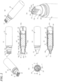
FIG. 1 ] Illustrative diagrams showing a hair applicator in its capped state, according to a first embodiment of the present invention, (a) is a perspective view from the front side, (b) is a view from the front side, (c) is a view from one side, (d) is a longitudinal section cut along a line D-D in (b), (e) is a view from the other side, (f) is a longitudinal section cut along a line F-F in (b), (g) is a perspective view from the rear side, and (h) is a view from the rear side. - [
FIG. 2 ] Illustrative diagrams showing the hair applicator ofFIG. 1 in its uncapped state, (a) is a perspective view from the front side, (b) is a view from the front side, (c) is a view from one side, (d) is a longitudinal section cut along a line D-D in (b), (e) is a view from the other side, (f) is a longitudinal section cut along a line F-F in (b), (g) is a perspective view from the rear side, and (h) is an enlarged perspective view showing the front end part. - [
FIG. 3 ] Part drawings showing the front barrel of the hair applicator ofFIG. 1 in its uncapped state, (a) is a perspective view from the front side, (b) is a view from the front side, (c) is a view from one side, (d) is a longitudinal section cut along a line D-D in (b), (e) is a view from the other side, (f) is a longitudinal section cut along a line F-F in (b), (g) is a perspective view from the rear side, (h) is a view from the rear side, and (i) is an enlarged perspective view showing the front end part. - [
FIG. 4 ] Part drawings showing an applying part of the hair applicator ofFIG. 1 , (a) is a side perspective view, (b) is a view from one side (wide side), and (c) is a view from the other side (narrow side). - [
FIG. 5 ] (a) is an enlarged perspective view of the vicinity of a comb in a front barrel of a comparative example, and (b) is an enlarged perspective view of the vicinity of a comb in a front barrel of a variational example 1. - [
FIG. 6 ] (a) is an enlarged perspective view of the vicinity of a comb in a front barrel of a comparative example, (b) is an enlarged side view of the vicinity of a comb in a front barrel of the first embodiment, and (c) is an enlarged perspective view of the vicinity of a comb in a front barrel of the first embodiment. - [
FIG. 7 ] Illustrative diagrams showing a hair applicator in its capped state, according to a second embodiment of the present invention, (a) is a perspective view from the front side, (b) is a view from the front side, (c) is a view from one side, (d) is a longitudinal section cut along a line D-D in (b), (e) is a view from the other side, (f) is a longitudinal section cut along a line F-F in (b), (g) is a perspective view from the rear side, and (h) is a view from the rear side. - [
FIG. 8 ] Illustrative diagrams showing the hair applicator ofFIG. 7 in its uncapped state, (a) is a perspective view from the front side, (b) is a view from the front side, (c) is a view from one side, (d) is a longitudinal section cut along a line D-D in (b), (e) is a view from the other side, (f) is a longitudinal section cut along a line F-F in (b), (g) is a perspective view from the rear side, and (h) is an enlarged perspective view showing the front end part. - [
FIG. 9 ] Part drawings showing the front barrel of the hair applicator ofFIG. 7 in its uncapped state, (a) is a perspective view from the front side, (b) is a view from the front side, (c) is a view from one side, (d) is a longitudinal section cut along a line D-D in (b), (e) is a view from the other side, (f) is a longitudinal section cut along a line F-F in (b), (g) is a perspective view from the rear side, (h) is a view from the rear side, and (i) is an enlarged perspective view showing the front end part. - [
FIG. 10 ] Part drawings showing an applying part of the hair applicator ofFIG. 7 , (a) is a side perspective view, (b) is a view from one side (wide side), and (c) is a view from the other side (narrow side). - [
FIG. 11 ] Illustrative diagrams showing a hair applicator in its capped state, according to a third embodiment of the present invention, (a) is a perspective view from the front side, (b) is a view from the front side, (c) is a view from one side, (d) is a longitudinal section cut along a line D-D in (b), (e) is a view from the other side, (f) is a longitudinal section cut along a line F-F in (b), (g) is a perspective view from the rear side, and (h) is a view from the rear side. - [
FIG. 12 ] Illustrative diagrams showing the hair applicator ofFIG. 11 in its uncapped state, (a) is a perspective view from the front side, (b) is a view from the front side, (c) is a view from one side, (d) is a longitudinal section cut along a line D-D in (b), (e) is a view from the other side, (f) is a longitudinal section cut along a line F-F in (b), (g) is a perspective view from the rear side, and (h) is an enlarged perspective view showing the front end part. - [
FIG. 13 ] Part drawings showing the front barrel of the hair applicator ofFIG. 11 in its uncapped state, (a) is a perspective view from the front side, (b) is a view from the front side, (c) is a view from one side, (d) is a longitudinal section cut along a line D-D in (b), (e) is view from the other side, (f) is a longitudinal section cut along a line F-F in (b), (g) is a perspective view from the rear side, (h) is a view from the rear side, and (i) is an enlarged perspective view showing the front end part. - [
FIG. 14 ] Part drawings showing the cap in the hair applicator ofFIG. 11 , (a) is a longitudinal section cut along a line A-A in (b), (b) is a view from the rear side, and (c) is a perspective view from the rear side. - Hereinafter, embodiments of the present invention will be described with reference to the accompanying drawings.
-
FIGS. 1 to 6 are illustrative diagrams showing a hair applicator according to the first embodiment. - As shown in
FIGS. 1 to 3 , the hair applicator according to the embodiment includes an applyingpart 10 of a porous material and acomb 12 havingcomb elements 12a, formed with the applyingpart 10. The hair applicator is an applicator for hair that can dispense a hair dye in the front barrel (corresponding to the "container") 14 from the applyingpart 10 to the hair when thecomb 12 combs the hair. - Detailedly, as shown in
FIG. 1 , the hair applicator has acap 16 detachably attached to afront end part 14a of thefront barrel 14 so as to cover the applyingpart 10. Thecap 16 prevents the applyingpart 10 from drying by putting aninner cap 16a in hermetic contact with the outer peripheral side of thefront end part 14a of thefront barrel 14. - As shown in
FIG. 2 , thefront barrel 14 has a substantially hollow cylindrical shape with thefront end part 14a formed in a spatulate flat appearance having an opening forward of the hollow. Thecomb 12 is formed in thefront end part 14a so as to surround the opening, and the applyingpart 10 is exposed from the opening. A tail plug (lid) 18 is fitted to the rear end of thefront barrel 14 to close the hollow inside thefront barrel 14 so as to provide a container function. In addition, anabsorbent fabric 20 is stuffed in the closed space in thefront barrel 14, and impregnated with the hair dye. - The applying
part 10 is arranged inside thecomb 12 of thefront barrel 14. The rear end of applyingpart 10 is inserted into the front portion of theabsorbent fabric 20, so that the hair dye of theabsorbent fabric 20 permeates the applyingpart 10. - As shown in
FIGS. 1 and2 , thefront barrel 14 is covered from the center to the rear with arear barrel 22. Therear barrel 22 has a cylindrical shape with a closed rear end, and arib 22a for preventing rotation of thefront barrel 14 is formed on the inner periphery along the axial direction. Therib 22a is formed as a projected portion such as a parallel rail. Thefront barrel 14 has arecess 14i formed along the axial direction on the outer surface in the rear portion thereof (seeFIG. 3 ). - The
recess 14i of thefront barrel 14 mates with the lockingrib 22a to prevent thefront barrel 14 from rotating with respect to therear barrel 22. - As shown in
FIGS. 1 and2 , thefront barrel 14 has amale thread 14b on the outer peripheral side of thefront end part 14a for thecap 16 to be screwed thereon. In addition, aflange 14c is formed on the outer periphery adjacent to the rear of themale screw 14b. Further, afitting rib 14d is formed behind theflange 14c on the outer periphery. - The
rear barrel 22 has an annular projectedportion 22b on the inner surface in the front part thereof. - When the rear part of the
front barrel 14 is pushed rearward into the front opening of therear barrel 22 until theflange 14c abuts therear barrel 22, the projectedportion 22b inside therear barrel 22 is engaged with therib 14d so that therear barrel 22 will not come off (fall out) from thefront barrel 14. - In addition, projected
portions 14e are formed inside thefront end part 14a of thefront barrel 14 to catch astep portion 10c of the applying part. - The applying
part 10 is formed of a porous material having a porosity of 80% or higher and a hardness under ISO7619A of less than A70, which dispenses a coating amount of 0.090 g/m or greater - Specifically, as shown in
FIG. 4 , the applyingpart 10 is given in the form of a flat plate having a greater width relative to the thickness. The applyingpart 10 is formed of a front portion (applying tip side) 10a of a width W1 and arear portion 10b of a width W2 smaller than W1, forming a substantially T-shape. - The applying
part 10 uses felt as the porous material in the embodiment. The dimensions of the applyingpart 10 are such that the thickness t is about 7 to 2 (mm), the width W1 of thefront portion 10a is wider than the width W2 of therear part 10b (W1> W2), and astep 10c is formed at the boundary between thefront portion 10a and therear portion 10b. The width W1 can be 15 to 10 (mm) and the width W2 can be 13 to 8 (mm). Further, the length of thefront portion 10a can be 15 to 10 (mm) and the length of therear portion 10b can be 13 to 8 (mm) . The rear endface of therear portion 10b contacts theabsorbent fabric 20, but can be made flat. - As shown in
FIG. 1 , in the state where the applyingpart 10 is attached to thefront barrel 14, thefront portion 10a of the width W1 serving as the applying tip is fitted inside of thefront end part 14a. Further, thestep 10c located at the boundary to therear portion 10b of the width W2 is locked by the projectedportions 14e formed in thefront end part 14a of thefront barrel 14. Therefore, this locking prevents the applyingpart 10 from sliding backward into theabsorbent fabric 20 in thefront barrel 14. - In the
comb 12, as shown inFIGS. 2 and5 , a plurality ofcomb elements 12a extending forward are formed integrally with thefront end part 14a of thefront barrel 14. - The
front end part 14a has a rectangular opening, and holds the applyingpart 10 therein. Thefront end part 14a is configured such that the applyingpart 10 is held by thecomb 12 on the front side with the tips of thecomb elements 12a project forward beyond the front end of the applyingpart 10. - In the
comb 12, as shown inFIGS. 2 and5 ,beams 12b for anti-falling (preventing the applyingpart 10 from falling forward) are formed so as to connect the opposingcomb elements 12a. In addition, thestep 10c abuts against the projectedportions 14e inside the front barrel 14 (thefront end part 14a) in the interior of thecomb 12 to prevent the applyingpart 10 from moving rearward. - Therefore, even if the applying
part 10 is made of a felt or the like that is softer than the applying part that is press-fitted in the conventional front barrel (Patent Document 1 and Patent Document 4), the applyingpart 10 is positioned and fixed on the front side by thebeams 12b, and on the rear side by the projectedportions 14e, so that the applyingpart 10 will not be displaced. - As described later, in the first embodiment, as shown in
FIGS. 2 and5(b) , thebeam 12b between thecomb elements 12a has a hollow 12b1 formed on the surface thereof. Further, the surface area of the tip of thecomb element 12a is specified to be 0.3 to 1.0 mm2. - As to the applying
part 10, the higher the porosity, the greater the coating amount. When the coating amount is 0.090 g/m or greater and the porous material has a porosity of 80% or higher and a hardness under ISO7619A of less than A70, the hardness is sufficient, so that it is possible to prevent the applying part from coming off from thefront end part 14a of thefront barrel 14. - Therefore, according to the hair applicator according to the first embodiment, the applying part can be fixed to the comb elements with a sufficient fixing force, and prevented from being displaced even by an impact from a fall while an ample coating amount can be secured.
- Yet, since the hardness of the applying
part 10 may degrade when the porosity is increased, thebeams 12b are provided between thecomb elements 12a of thefront end part 14a, as described above. As shown in detail inFIGS. 2 and5 , thebeams 12b provide a stopper function for the applyingpart 10. - With the hair applicator according to the embodiment, an evaluation test was performed on the applying
part 10 that was specified so that the coating amount was 0.090 g/m or greater and the porous material had a porosity of 80% or higher and a hardness under ISO7619A of less than A70. - The felt cores for the evaluated applying parts are as shown in Table 1 below.
[Table 1] Felt Core Porosity Hardness Applied Amount Example 1 90% A40 0.115g Example 2 81% A60 0.104g Comp. Example 1 73% A80 0.079g Comp. Example 2 68% A55 0.069g - In Table 1, the applying parts of Examples 1 and 2 of the present invention were felt cores, and the coating amount was 0.115 (g) in Example 1 and 0.104 (g) in Example 2.
- The applying parts of Comparative Examples 1 and 2 were felt cores, and the coating amount was 0.079 (g) in Comparative Example 1 and 0.069 (g) in Comparative Example 2.
- The porosity of each of Examples 1 and 2 and Comparative Examples 1 and 2 is an actual measurement value, which was obtained as the volume converted from the full filling weight of ethanol.
- The hardness is also an actual measurement value, which was obtained by using a rubber hardness meter (conforming to ISO7619A).
- The investigation of the amount of liquid applied in Examples 1 and 2 and Comparative Examples 1 and 2 was based on the measurement of the applied material by the following hair bundle application test.
- The object to be coated:

- Application speed: 10cm/sec (second)
- Preparation for application test: put a sponge in zipper bag on wall.
- Application test procedures:
- (1) Set two hair bundles on the sponge;
- (2) "Apply 10cm -> 1sec break" × 10 strokes -> measure the liquid consumption;
- (3) Turn over the hair bundles;
- (4) "Apply 10cm -> 1sec break" × 10 strokes -> measure the liquid consumption; and
- (5) Prepare new hair bundles and return to (1).
- The results obtained by repeating (1) to (5) ten times are shown in Table 1.
- As shown in Table 1, each coating amount was 0.115 (g) in Example 1 and 0.104 (g) in Example 2, whereas the coating amount was 0.079 (g) in Comparative Example 1, and coating amount of Comparative Example 2 was 0.069 (g) . The applicators of Examples 1 and 2 have a coating amount of 10 to 12 times or more that of the applicators of Comparative Examples 1 and 2. Thus, according to the present invention, it has become clear that a markedly sufficient amount of coating (approximately an order of magnitude greater) can be applied to the hair.
- Next, measures against skin stains in the hair applicator of the first embodiment will be described.
- In
FIG. 5 , (a) shows a comparative example, and (b) shows a variational example 1. - Because the
comb 12 of thefront barrel 14 has its front end located ahead of the applying part, if the front end of thecomb 12 is formed flat as in the comparative example shown inFIG. 5(a) , the fluid may adhere to the skin. - More specifically, the cosmetic (application liquid) applied to the hair transfers to the flat top surface of the
comb 12 and the top surface touches the skin so that the hair cosmetic is transferred to adhere to and stain the skin. - To deal with this, in the variational example 1 shown in
FIG. 5B , the hollow 12b1 is formed on the front endface of thebeam 12b of thecomb 12 to reduce the contact area between the skin and thecomb 12, so that transfer of the liquid can be avoided. - Another countermeasure against staining will be described with reference to
FIG. 6 . - In
FIG. 6 , (a) shows a comparative example, and (b) and (c) show the front barrel of the first embodiment. - In the hair applicator according to the first embodiment, the cosmetic is more likely to adhere to the skin than in the conventional product. That is, as the
comb elements 12a of thecomb 12 are reduced in number, the contact area is reduced, hence it became easier to sink into the skin, and the applyingpart 10 easily comes into direct contact with the skin. - To deal with this, though the
comb 12 in the comparative example shown inFIG. 6A has two pairs ofcomb elements 12a, thecomb 12 of the first embodiment shown inFIGS. 6B and 6C has five pairs ofcomb elements 12a so as to suppress sinking into the skin and make staining the skin unlikely. - In addition, as shown in detail in
FIG. 6C , in the first embodiment, thebeam 12b is provided in every other pair of thecomb elements 12a among the five pairs in thecomb 12, and hollows 12b1 are also formed. Specifically, in the first embodiment, the area of the flat part in the front end of thecomb part 12 was 0.4 mm2, and the gap between thecomb elements 12a was 1.3 mm. - The step height of the hollow 12b1 in the
preferred comb 12 was found to be 0.5 to 0.9 mm. - Next, a hair applicator according to a second embodiment will be described.
-
FIGS. 7 to 10 are illustrative diagrams of a hair applicator according to a second embodiment, andFIG. 10 is an illustrative view of an applying part. The hair applicator according to the first embodiment is configured such that thecomb elements 12a of thecomb 12 are arranged and formed in the direction perpendicular to the center axis of thefront barrel 14. On the other hand, in the hair applicator according to the second embodiment, thecomb elements 12a of thecomb 12 are arranged and formed in an inclined manner at an angle θ with respect to the center axis of the front barrel 14 (indicated by the symbol "C" inFIG. 8 ). - Corresponding to the formation and arrangement of the
comb elements 12a with respect to the center axis of thefront barrel 14, the applyingpart 10 is slanted forming afront part 10a of the facet inclined at the angle θ with respect to the center axis (indicated by the symbol "C" inFIG. 10 ) . - As to the other parts, the same components as those in the first embodiment are allotted with the same reference numerals.
- According to the second embodiment, since the arrangement of the
comb elements 12a of thecomb 12 is slanted, the applicator can be obliquely applied to the hair unlike the first embodiment in which the applicator is applied vertically. It is hence suitable for application to the hairline and the like. Others are the same as in the first embodiment. - Next, a hair applicator according to a third embodiment will be described.
-
FIGS. 11 and12 are illustrative diagrams of the hair applicator according to the third embodiment.FIG. 13 is an illustrative diagram of a front barrel, andFIG. 14 is an illustrative diagram of an applying part. The same parts as those in the first embodiment shown inFIGS. 1 to 4 are denoted by the same reference numerals. In the third embodiment, the applyingpart 10 and theabsorbent fabric 20 are the same as those in the first embodiment, and those in the second embodiment can also be adopted. The third embodiment is different from the first and second embodiments in the configurations other than the applyingpart 10 and theabsorbent fabric 20. - As shown in
FIGS. 11 and12 , in the hair applicator of the third embodiment, a container for accommodating theabsorbent fabric 20 is formed with the rear end of thefront barrel 14 closed by atail plug 18. Thetail plug 18 abuts theinner surface 22c (bottom surface) at the rear end of therear barrel 22. The front part of thetail plug 18 serves as a part closing the rear end of thefront barrel 14. The rear end of thetail plug 18 that is greater in diameter than the front end thereof serves as a part closing the rear end of therear barrel 22. - The hair applicator also has a
cap 16 that covers the applyingpart 10 and thecomb 12, as shown inFIG. 11 . Thecap 16 can be fitted to athread 14b on the front barrel (forming a container with the tail plug 18) 14 by a thread (female thread) 16b. Thecap 16 and thefront barrel 14 are formed withprojections 16c (seeFIG. 14 ) and 14f, which ride over each other into a fitted state. - Detailedly, as shown in
FIG. 13 , thefront barrel 14 has a pair ofprojections 14f that allow theprojections 16c (not shown) to ride over. Eachprojection 14f protrudes radially outward adjacent to the front side of theflange 14c. - A
rib 14g for stopping the rotation of thefront barrel 14 relative to therear barrel 22 is projectively formed on the rear side of theflange 14c. Theprojection 14f and therib 14g are formed at the same position with respect to the circumferential direction of thefront barrel 14. Therib 14g is formed as a projection on the inner surface of the front barrel so as to be engageable with arecess 22d to prevent therear barrel 22 from rotating (seeFIG. 12 ) . Therib 14g and therecess 22d can be appropriately provided in any form as long as they are engaged with each other. - As shown in
FIG. 13 , thefront barrel 14 has thecomb 12 in thefront end part 14a. Agroove 14h for air replacement is formed on the inner side surface of acomb element 12a in contact with the applyingpart 10. As shown inFIG. 13 , thegroove 14h is formed in a portion facing one side surface of the applyingpart 10. - As shown in
FIG. 14 , thecap 16 has aninner cap 16a fitted and accommodated inside a main body forming an outer covering. In the front end of the cap,ribs 16d for receiving the application liquid are formed radially on the inner surface of the inner cap. There are twoprojections 16c in thecap 16 shown inFIG. 14 and twoprojections 14f in the front barrel 14 (seeFIGS. 12 and13 ). However, one or three ormore projections - According to the third embodiment, the
projections cap 16 and thefront barrel 14, respectively. Therefore, when thecap 16 is screw-fitted to thefront barrel 14, theprojections 16c ride over theprojections 14f to create a clicking sensation when riding over. - The user can make sure from the click feeling that the
cap 16 and thefront barrel 14 have been fitted when thecap 16 is closed. Also, once theprojections - Since the
air replacement groove 14h is provided on the inner surface of thecomb 12, air-liquid replacement can be smoothly performed in the applyingpart 10 and others. Thus, the air displacement from the applying part can be ensured, so that it is possible to prevent a supply shortage at the time of application. - In addition, the
tail plug 18 abuts theinner surface 22c (bottom surface) at the rear end of therear barrel 22, to reliably prevent the tail plug 18 from falling off inside therear barrel 22, thereby making it possible to prevent theabsorbent fabric 20 from falling from the applyingpart 10. - The hair applicator of the present invention can be used not only for human hair but also for animals.
-
- 10
- applying part
- 12
- comb
- 12a
- comb element
- 12b
- beam
- 12b1
- hollow
- 14
- front barrel
- 14a
- front end part
- 14b
- male thread
- 14c
- flange
- 14d
- rib
- 14e
- projected portion
- 14f
- projection
- 14h
- groove
- 16
- cap
- 16b
- thread
- 16c
- projection
- 20
- absorbent fabric
- 22
- rear barrel
Claims (5)
- A hair applicator comprising: an applying part (10) made of a porous material; and a comb (12) having a plurality of comb elements (12a) provided with the applying part, to thereby apply a hair dye from a container (14) through the applying part to the hair while combing the hair with the comb, whereinthe comb elements hold the applying part on the front side thereof, and the comb elements are projected forward from the applying part, andbeams (12b) for preventing the applying part from falling forward are formed in the comb so as to connect opposing comb elements,characterized in that the porous material has a porosity of 80% or higher and a hardness under IS07619A of less than A70,the coating amount by the applying part is 0.090 g/m or greater.
- The hair applicator according to claim 1, wherein a hollow is formed on a surface of the comb element.
- The hair applicator according to claim 1 or 2, wherein the surface area of a front endface of the comb element is 0.3 to 1.0 mm2.
- The hair applicator according to any of claims 1-3, further comprising a cap (16) that covers the applying part and the comb, wherein the cap can be fitted to the container by screw fitting, and the cap and the container are formed with projections that ride over each other into a fitted state.
- The hair applicator according to any of claim 1-4, wherein a groove (14h) for air replacement is formed on an inner surface of the comb.
Applications Claiming Priority (2)
| Application Number | Priority Date | Filing Date | Title |
|---|---|---|---|
| JP2017206103 | 2017-10-25 | ||
| PCT/JP2018/039566 WO2019082944A1 (en) | 2017-10-25 | 2018-10-24 | Applicator for hair |
Publications (3)
| Publication Number | Publication Date |
|---|---|
| EP3701829A1 EP3701829A1 (en) | 2020-09-02 |
| EP3701829A4 EP3701829A4 (en) | 2021-07-21 |
| EP3701829B1 true EP3701829B1 (en) | 2023-08-16 |
Family
ID=66246487
Family Applications (1)
| Application Number | Title | Priority Date | Filing Date |
|---|---|---|---|
| EP18870514.9A Active EP3701829B1 (en) | 2017-10-25 | 2018-10-24 | Applicator for hair |
Country Status (5)
| Country | Link |
|---|---|
| US (1) | US11641922B2 (en) |
| EP (1) | EP3701829B1 (en) |
| JP (1) | JP7281407B2 (en) |
| CN (1) | CN111278325B (en) |
| WO (1) | WO2019082944A1 (en) |
Family Cites Families (18)
| Publication number | Priority date | Publication date | Assignee | Title |
|---|---|---|---|---|
| JPS5019700U (en) * | 1973-06-22 | 1975-03-05 | ||
| US4376441A (en) * | 1980-10-14 | 1983-03-15 | Theodore Duncan | Hair treatment applicator |
| JP2899460B2 (en) | 1991-10-17 | 1999-06-02 | ユニチカ株式会社 | Felt pen core material and method for producing the same |
| US5325878A (en) * | 1992-07-17 | 1994-07-05 | Mckay William D | Fluid dispensing comb |
| JPH07223396A (en) | 1994-02-09 | 1995-08-22 | Unitika Ltd | Core material of felt-tip pen and production thereof |
| FR2744104B1 (en) * | 1996-01-29 | 1998-03-20 | Oreal | DEVICE FOR PACKAGING, DISPENSING AND APPLYING A GEL OR FOAM |
| JPH11169224A (en) | 1997-12-11 | 1999-06-29 | Shiseido Co Ltd | Applicator for head hair |
| FR2807295B1 (en) | 2000-04-05 | 2002-10-18 | Oreal | APPLICATION MEMBER FOR APPLYING A PRODUCT TO A MEDIUM AND APPLICATION ASSEMBLY THUS EQUIPPED |
| JP2004154173A (en) * | 2002-11-01 | 2004-06-03 | Mitsubishi Pencil Co Ltd | Liquid cosmetic applicator |
| JP4292881B2 (en) * | 2003-06-11 | 2009-07-08 | 花王株式会社 | Cap with comb |
| JP4726439B2 (en) * | 2004-06-04 | 2011-07-20 | 三菱鉛筆株式会社 | Hair applicator and cosmetic container with the applicator |
| EP1769697A4 (en) | 2004-07-08 | 2008-03-05 | Mitsubishi Pencil Co | Applicator for hair and cosmetic container with the applicator |
| DE102005044019A1 (en) | 2005-09-14 | 2007-03-22 | Georg Menshen Gmbh & Co. Kg | Device for applying liquid media such as hair cosmetics and dying or bleaching liquids onto hair comprises parallel rows of wicks forming the teeth of a comb and containing liquid medium from a storage reservoir |
| JP4971656B2 (en) | 2006-03-28 | 2012-07-11 | シヤチハタ株式会社 | Hair applicator |
| JP6406972B2 (en) | 2014-10-20 | 2018-10-17 | 三菱鉛筆株式会社 | Hair applicator |
| JP2016087068A (en) | 2014-11-04 | 2016-05-23 | 三菱鉛筆株式会社 | Hair applicator |
| JP2017104482A (en) | 2015-04-14 | 2017-06-15 | 三菱鉛筆株式会社 | Applicator for hair |
| JP6654005B2 (en) * | 2015-07-31 | 2020-02-26 | ホーユー株式会社 | Hair treatment agent applicator and hair treatment device to which hair treatment agent application device is attached |
-
2018
- 2018-10-24 JP JP2019551216A patent/JP7281407B2/en active Active
- 2018-10-24 US US16/758,441 patent/US11641922B2/en active Active
- 2018-10-24 WO PCT/JP2018/039566 patent/WO2019082944A1/en unknown
- 2018-10-24 CN CN201880069382.XA patent/CN111278325B/en active Active
- 2018-10-24 EP EP18870514.9A patent/EP3701829B1/en active Active
Also Published As
| Publication number | Publication date |
|---|---|
| CN111278325A (en) | 2020-06-12 |
| US20200260830A1 (en) | 2020-08-20 |
| CN111278325B (en) | 2023-03-24 |
| EP3701829A1 (en) | 2020-09-02 |
| WO2019082944A1 (en) | 2019-05-02 |
| JPWO2019082944A1 (en) | 2020-11-12 |
| EP3701829A4 (en) | 2021-07-21 |
| JP7281407B2 (en) | 2023-05-25 |
| US11641922B2 (en) | 2023-05-09 |
Similar Documents
| Publication | Publication Date | Title |
|---|---|---|
| US9668564B2 (en) | Cosmetic product applicator, device and associated method | |
| US10888145B2 (en) | Cosmetic applicator | |
| US9681725B2 (en) | Cosmetic product applicator, associated head and device | |
| US20030089379A1 (en) | Product applicator for eyelashes and/or eyebrows, and method of product application | |
| US20040161285A1 (en) | Applicator including an applicator element for applying a substance, in particular a cosmetic or another care product | |
| JP2003235641A (en) | Cosmetic storing and applying device | |
| JP2000333728A (en) | Device for packaging and applying substance and device having wiper member with slot | |
| US20020174877A1 (en) | Devices and methods for applying a product to hair | |
| EP3462976B1 (en) | Cosmetic applicator having molded brush and comb portions | |
| JPH11346827A (en) | Coating applicator of composition to keratin fiber | |
| EP3701829B1 (en) | Applicator for hair | |
| JP2004223266A (en) | Applicator including applicator element for applying material, especially cosmetics and/or care goods, and device and method using the same | |
| JP2012232104A (en) | Cosmetic material applying device | |
| JP5716056B2 (en) | Lip cosmetic applicator | |
| JP5718983B2 (en) | Lip cosmetic applicator | |
| KR20150105726A (en) | Mascara | |
| JP2010131329A (en) | Lip cosmetics applicator | |
| JP6406972B2 (en) | Hair applicator | |
| JP5275664B2 (en) | Applicator | |
| JPH0870929A (en) | Hair dressing tool | |
| JP6532693B2 (en) | Hair applicator | |
| JP7170005B2 (en) | Processing agent applicator and processing products | |
| JP2006263233A (en) | Liquid cosmetics container | |
| JP4749776B2 (en) | Combing container with comb | |
| JPS628826Y2 (en) |
Legal Events
| Date | Code | Title | Description |
|---|---|---|---|
| STAA | Information on the status of an ep patent application or granted ep patent |
Free format text: STATUS: THE INTERNATIONAL PUBLICATION HAS BEEN MADE |
|
| PUAI | Public reference made under article 153(3) epc to a published international application that has entered the european phase |
Free format text: ORIGINAL CODE: 0009012 |
|
| STAA | Information on the status of an ep patent application or granted ep patent |
Free format text: STATUS: REQUEST FOR EXAMINATION WAS MADE |
|
| 17P | Request for examination filed |
Effective date: 20200525 |
|
| AK | Designated contracting states |
Kind code of ref document: A1 Designated state(s): AL AT BE BG CH CY CZ DE DK EE ES FI FR GB GR HR HU IE IS IT LI LT LU LV MC MK MT NL NO PL PT RO RS SE SI SK SM TR |
|
| AX | Request for extension of the european patent |
Extension state: BA ME |
|
| DAV | Request for validation of the european patent (deleted) | ||
| DAX | Request for extension of the european patent (deleted) | ||
| A4 | Supplementary search report drawn up and despatched |
Effective date: 20210617 |
|
| RIC1 | Information provided on ipc code assigned before grant |
Ipc: A45D 19/02 20060101AFI20210611BHEP Ipc: A45D 24/22 20060101ALI20210611BHEP Ipc: A45D 24/24 20060101ALI20210611BHEP |
|
| GRAP | Despatch of communication of intention to grant a patent |
Free format text: ORIGINAL CODE: EPIDOSNIGR1 |
|
| STAA | Information on the status of an ep patent application or granted ep patent |
Free format text: STATUS: GRANT OF PATENT IS INTENDED |
|
| INTG | Intention to grant announced |
Effective date: 20230329 |
|
| P01 | Opt-out of the competence of the unified patent court (upc) registered |
Effective date: 20230523 |
|
| GRAS | Grant fee paid |
Free format text: ORIGINAL CODE: EPIDOSNIGR3 |
|
| GRAA | (expected) grant |
Free format text: ORIGINAL CODE: 0009210 |
|
| STAA | Information on the status of an ep patent application or granted ep patent |
Free format text: STATUS: THE PATENT HAS BEEN GRANTED |
|
| AK | Designated contracting states |
Kind code of ref document: B1 Designated state(s): AL AT BE BG CH CY CZ DE DK EE ES FI FR GB GR HR HU IE IS IT LI LT LU LV MC MK MT NL NO PL PT RO RS SE SI SK SM TR |
|
| REG | Reference to a national code |
Ref country code: CH Ref legal event code: EP |
|
| REG | Reference to a national code |
Ref country code: DE Ref legal event code: R096 Ref document number: 602018055675 Country of ref document: DE |
|
| REG | Reference to a national code |
Ref country code: IE Ref legal event code: FG4D |
|
| REG | Reference to a national code |
Ref country code: LT Ref legal event code: MG9D |
|
| REG | Reference to a national code |
Ref country code: NL Ref legal event code: MP Effective date: 20230816 |
|
| RAP4 | Party data changed (patent owner data changed or rights of a patent transferred) |
Owner name: MITSUBISHI PENCIL COMPANY, LIMITED |
|
| REG | Reference to a national code |
Ref country code: AT Ref legal event code: MK05 Ref document number: 1599131 Country of ref document: AT Kind code of ref document: T Effective date: 20230816 |
|
| PG25 | Lapsed in a contracting state [announced via postgrant information from national office to epo] |
Ref country code: GR Free format text: LAPSE BECAUSE OF FAILURE TO SUBMIT A TRANSLATION OF THE DESCRIPTION OR TO PAY THE FEE WITHIN THE PRESCRIBED TIME-LIMIT Effective date: 20231117 |
|
| PG25 | Lapsed in a contracting state [announced via postgrant information from national office to epo] |
Ref country code: IS Free format text: LAPSE BECAUSE OF FAILURE TO SUBMIT A TRANSLATION OF THE DESCRIPTION OR TO PAY THE FEE WITHIN THE PRESCRIBED TIME-LIMIT Effective date: 20231216 |
|
| PG25 | Lapsed in a contracting state [announced via postgrant information from national office to epo] |
Ref country code: SE Free format text: LAPSE BECAUSE OF FAILURE TO SUBMIT A TRANSLATION OF THE DESCRIPTION OR TO PAY THE FEE WITHIN THE PRESCRIBED TIME-LIMIT Effective date: 20230816 Ref country code: RS Free format text: LAPSE BECAUSE OF FAILURE TO SUBMIT A TRANSLATION OF THE DESCRIPTION OR TO PAY THE FEE WITHIN THE PRESCRIBED TIME-LIMIT Effective date: 20230816 Ref country code: PT Free format text: LAPSE BECAUSE OF FAILURE TO SUBMIT A TRANSLATION OF THE DESCRIPTION OR TO PAY THE FEE WITHIN THE PRESCRIBED TIME-LIMIT Effective date: 20231218 Ref country code: NO Free format text: LAPSE BECAUSE OF FAILURE TO SUBMIT A TRANSLATION OF THE DESCRIPTION OR TO PAY THE FEE WITHIN THE PRESCRIBED TIME-LIMIT Effective date: 20231116 Ref country code: NL Free format text: LAPSE BECAUSE OF FAILURE TO SUBMIT A TRANSLATION OF THE DESCRIPTION OR TO PAY THE FEE WITHIN THE PRESCRIBED TIME-LIMIT Effective date: 20230816 Ref country code: LV Free format text: LAPSE BECAUSE OF FAILURE TO SUBMIT A TRANSLATION OF THE DESCRIPTION OR TO PAY THE FEE WITHIN THE PRESCRIBED TIME-LIMIT Effective date: 20230816 Ref country code: LT Free format text: LAPSE BECAUSE OF FAILURE TO SUBMIT A TRANSLATION OF THE DESCRIPTION OR TO PAY THE FEE WITHIN THE PRESCRIBED TIME-LIMIT Effective date: 20230816 Ref country code: IS Free format text: LAPSE BECAUSE OF FAILURE TO SUBMIT A TRANSLATION OF THE DESCRIPTION OR TO PAY THE FEE WITHIN THE PRESCRIBED TIME-LIMIT Effective date: 20231216 Ref country code: HR Free format text: LAPSE BECAUSE OF FAILURE TO SUBMIT A TRANSLATION OF THE DESCRIPTION OR TO PAY THE FEE WITHIN THE PRESCRIBED TIME-LIMIT Effective date: 20230816 Ref country code: GR Free format text: LAPSE BECAUSE OF FAILURE TO SUBMIT A TRANSLATION OF THE DESCRIPTION OR TO PAY THE FEE WITHIN THE PRESCRIBED TIME-LIMIT Effective date: 20231117 Ref country code: FI Free format text: LAPSE BECAUSE OF FAILURE TO SUBMIT A TRANSLATION OF THE DESCRIPTION OR TO PAY THE FEE WITHIN THE PRESCRIBED TIME-LIMIT Effective date: 20230816 Ref country code: AT Free format text: LAPSE BECAUSE OF FAILURE TO SUBMIT A TRANSLATION OF THE DESCRIPTION OR TO PAY THE FEE WITHIN THE PRESCRIBED TIME-LIMIT Effective date: 20230816 |
|
| PGFP | Annual fee paid to national office [announced via postgrant information from national office to epo] |
Ref country code: FR Payment date: 20231009 Year of fee payment: 6 |
|
| PG25 | Lapsed in a contracting state [announced via postgrant information from national office to epo] |
Ref country code: PL Free format text: LAPSE BECAUSE OF FAILURE TO SUBMIT A TRANSLATION OF THE DESCRIPTION OR TO PAY THE FEE WITHIN THE PRESCRIBED TIME-LIMIT Effective date: 20230816 |
|
| PG25 | Lapsed in a contracting state [announced via postgrant information from national office to epo] |
Ref country code: ES Free format text: LAPSE BECAUSE OF FAILURE TO SUBMIT A TRANSLATION OF THE DESCRIPTION OR TO PAY THE FEE WITHIN THE PRESCRIBED TIME-LIMIT Effective date: 20230816 |
|
| PG25 | Lapsed in a contracting state [announced via postgrant information from national office to epo] |
Ref country code: SM Free format text: LAPSE BECAUSE OF FAILURE TO SUBMIT A TRANSLATION OF THE DESCRIPTION OR TO PAY THE FEE WITHIN THE PRESCRIBED TIME-LIMIT Effective date: 20230816 Ref country code: RO Free format text: LAPSE BECAUSE OF FAILURE TO SUBMIT A TRANSLATION OF THE DESCRIPTION OR TO PAY THE FEE WITHIN THE PRESCRIBED TIME-LIMIT Effective date: 20230816 Ref country code: ES Free format text: LAPSE BECAUSE OF FAILURE TO SUBMIT A TRANSLATION OF THE DESCRIPTION OR TO PAY THE FEE WITHIN THE PRESCRIBED TIME-LIMIT Effective date: 20230816 Ref country code: EE Free format text: LAPSE BECAUSE OF FAILURE TO SUBMIT A TRANSLATION OF THE DESCRIPTION OR TO PAY THE FEE WITHIN THE PRESCRIBED TIME-LIMIT Effective date: 20230816 Ref country code: DK Free format text: LAPSE BECAUSE OF FAILURE TO SUBMIT A TRANSLATION OF THE DESCRIPTION OR TO PAY THE FEE WITHIN THE PRESCRIBED TIME-LIMIT Effective date: 20230816 Ref country code: CZ Free format text: LAPSE BECAUSE OF FAILURE TO SUBMIT A TRANSLATION OF THE DESCRIPTION OR TO PAY THE FEE WITHIN THE PRESCRIBED TIME-LIMIT Effective date: 20230816 Ref country code: SK Free format text: LAPSE BECAUSE OF FAILURE TO SUBMIT A TRANSLATION OF THE DESCRIPTION OR TO PAY THE FEE WITHIN THE PRESCRIBED TIME-LIMIT Effective date: 20230816 |