EP3701682B1 - Verfahren, steuerungsmanager und steuermittel zum ermöglichen einer verbindung zwischen einem schalter eines kommunikationsnetzes und eines schaltreglers - Google Patents
Verfahren, steuerungsmanager und steuermittel zum ermöglichen einer verbindung zwischen einem schalter eines kommunikationsnetzes und eines schaltreglers Download PDFInfo
- Publication number
- EP3701682B1 EP3701682B1 EP18785324.7A EP18785324A EP3701682B1 EP 3701682 B1 EP3701682 B1 EP 3701682B1 EP 18785324 A EP18785324 A EP 18785324A EP 3701682 B1 EP3701682 B1 EP 3701682B1
- Authority
- EP
- European Patent Office
- Prior art keywords
- switch
- controller
- agent
- controllers
- manager
- Prior art date
- Legal status (The legal status is an assumption and is not a legal conclusion. Google has not performed a legal analysis and makes no representation as to the accuracy of the status listed.)
- Active
Links
Images


Classifications
-
- H—ELECTRICITY
- H04—ELECTRIC COMMUNICATION TECHNIQUE
- H04L—TRANSMISSION OF DIGITAL INFORMATION, e.g. TELEGRAPHIC COMMUNICATION
- H04L41/00—Arrangements for maintenance, administration or management of data switching networks, e.g. of packet switching networks
- H04L41/08—Configuration management of networks or network elements
- H04L41/0896—Bandwidth or capacity management, i.e. automatically increasing or decreasing capacities
- H04L41/0897—Bandwidth or capacity management, i.e. automatically increasing or decreasing capacities by horizontal or vertical scaling of resources, or by migrating entities, e.g. virtual resources or entities
-
- H—ELECTRICITY
- H04—ELECTRIC COMMUNICATION TECHNIQUE
- H04L—TRANSMISSION OF DIGITAL INFORMATION, e.g. TELEGRAPHIC COMMUNICATION
- H04L41/00—Arrangements for maintenance, administration or management of data switching networks, e.g. of packet switching networks
- H04L41/04—Network management architectures or arrangements
- H04L41/046—Network management architectures or arrangements comprising network management agents or mobile agents therefor
-
- H—ELECTRICITY
- H04—ELECTRIC COMMUNICATION TECHNIQUE
- H04L—TRANSMISSION OF DIGITAL INFORMATION, e.g. TELEGRAPHIC COMMUNICATION
- H04L41/00—Arrangements for maintenance, administration or management of data switching networks, e.g. of packet switching networks
- H04L41/12—Discovery or management of network topologies
- H04L41/122—Discovery or management of network topologies of virtualised topologies, e.g. software-defined networks [SDN] or network function virtualisation [NFV]
-
- H—ELECTRICITY
- H04—ELECTRIC COMMUNICATION TECHNIQUE
- H04L—TRANSMISSION OF DIGITAL INFORMATION, e.g. TELEGRAPHIC COMMUNICATION
- H04L41/00—Arrangements for maintenance, administration or management of data switching networks, e.g. of packet switching networks
- H04L41/40—Arrangements for maintenance, administration or management of data switching networks, e.g. of packet switching networks using virtualisation of network functions or resources, e.g. SDN or NFV entities
-
- H—ELECTRICITY
- H04—ELECTRIC COMMUNICATION TECHNIQUE
- H04L—TRANSMISSION OF DIGITAL INFORMATION, e.g. TELEGRAPHIC COMMUNICATION
- H04L43/00—Arrangements for monitoring or testing data switching networks
- H04L43/08—Monitoring or testing based on specific metrics, e.g. QoS, energy consumption or environmental parameters
- H04L43/0805—Monitoring or testing based on specific metrics, e.g. QoS, energy consumption or environmental parameters by checking availability
- H04L43/0811—Monitoring or testing based on specific metrics, e.g. QoS, energy consumption or environmental parameters by checking availability by checking connectivity
-
- H—ELECTRICITY
- H04—ELECTRIC COMMUNICATION TECHNIQUE
- H04L—TRANSMISSION OF DIGITAL INFORMATION, e.g. TELEGRAPHIC COMMUNICATION
- H04L43/00—Arrangements for monitoring or testing data switching networks
- H04L43/20—Arrangements for monitoring or testing data switching networks the monitoring system or the monitored elements being virtualised, abstracted or software-defined entities, e.g. SDN or NFV
-
- H—ELECTRICITY
- H04—ELECTRIC COMMUNICATION TECHNIQUE
- H04L—TRANSMISSION OF DIGITAL INFORMATION, e.g. TELEGRAPHIC COMMUNICATION
- H04L61/00—Network arrangements, protocols or services for addressing or naming
- H04L61/50—Address allocation
- H04L61/5007—Internet protocol [IP] addresses
- H04L61/5014—Internet protocol [IP] addresses using dynamic host configuration protocol [DHCP] or bootstrap protocol [BOOTP]
-
- H—ELECTRICITY
- H04—ELECTRIC COMMUNICATION TECHNIQUE
- H04L—TRANSMISSION OF DIGITAL INFORMATION, e.g. TELEGRAPHIC COMMUNICATION
- H04L41/00—Arrangements for maintenance, administration or management of data switching networks, e.g. of packet switching networks
- H04L41/08—Configuration management of networks or network elements
- H04L41/0803—Configuration setting
- H04L41/0813—Configuration setting characterised by the conditions triggering a change of settings
- H04L41/0816—Configuration setting characterised by the conditions triggering a change of settings the condition being an adaptation, e.g. in response to network events
-
- H—ELECTRICITY
- H04—ELECTRIC COMMUNICATION TECHNIQUE
- H04L—TRANSMISSION OF DIGITAL INFORMATION, e.g. TELEGRAPHIC COMMUNICATION
- H04L41/00—Arrangements for maintenance, administration or management of data switching networks, e.g. of packet switching networks
- H04L41/08—Configuration management of networks or network elements
- H04L41/0894—Policy-based network configuration management
-
- H—ELECTRICITY
- H04—ELECTRIC COMMUNICATION TECHNIQUE
- H04L—TRANSMISSION OF DIGITAL INFORMATION, e.g. TELEGRAPHIC COMMUNICATION
- H04L43/00—Arrangements for monitoring or testing data switching networks
- H04L43/10—Active monitoring, e.g. heartbeat, ping or trace-route
Definitions
- the present disclosure relates generally to a controller manager, a local controller agent and methods therein, for enabling a connection between a switch of a communication network and a switch controller that performs logic switch operations.
- An SDN contains various nodes and switches for data transport, which nodes are commonly referred to as “network devices" in this field.
- the switches in an SDN are thus used for handling and communicating data traffic, also referred to as data or traffic flows, in the network.
- the network devices of an SDN may include various switches, routers and firewalls which operate according to software or data programs which thus control their operation. This description is mainly concerned with the control of switches, including basically any nodes in the network where switching of data traffic take place.
- an SDN basically separates a control layer from a forwarding layer and provides an abstract topology of network resources to a logically centralized controller which may be employed to control the operation of switches in the SDN.
- a controller is referred to as a "switch controller", although any of the terms “controller” and “SDN controller” could also be used to denote a switch controller.
- Switch controllers may be implemented as processing resources or the like in remote data centers to serve and control operation of various switches in a communication network such as an SDN. Switch controllers communicate with switches using a protocol, such as OpenFlow, which consequently connects the control layer to the forwarding layer. It can be said that network devices capable of using OpenFlow are "Open Flow-enabled".
- the SDN controllers such as an Open Network Operating System ONOS
- OOS Open Network Operating System
- a distributed ONOS controller may be deployed to handle the network devices in a large Wide Area Network, WAN.
- a switch can be configured to connect to several controller nodes such as switch controllers. To do so, the switch needs to be configured with a list of the controllers' IP addresses. When a switch connects to multiple switch controllers, one controller will become a master controller while other controllers will remain in slave mode. The process of appointing a master controller may be executed between switch controllers, but it is also possible to set Master controller using Representational State Transfer, REST, Application Program Interfaces, APIs, provided by the controllers.
- a method is performed by a controller manager, located externally to a communication network, for enabling a switch of the communication network to be controlled by a switch controller that performs logic switch operations, the switch controller belonging to a set of switch controllers.
- the controller manager obtains, from a local controller agent, measurements related to connectivity to the set of switch controllers.
- the controller manager selects, in response to receiving a connection request for the switch from the local controller-agent, at least one switch controller in the set of switch controllers based on the obtained measurements, to control said switch, and instructs the local controller agent to set up a connection between the switch and the selected at least one switch controller, by sending to the local controller agent connectivity rules, the connectivity rules determining to which one or more switch controllers the switch should be connected.
- a controller manager is arranged to enable a switch of a communication network to be controlled by a switch controller that performs logic switch operations, the switch controller belonging to a set of switch controllers.
- the controller manager is configured to obtain from a local controller agent, measurements related to connectivity to the set of switch controllers.
- the controller manager is further configured to select, in response to receiving a connection request for the switch from the local controller agent, at least one switch controller in the set of switch controllers based on the obtained measurements, to control said switch, and to instruct the local controller agent to set up a connection between the switch and the selected at least one switch controller by sending to the local controller agent connectivity rules, the connectivity rules determining to which one or more switch controllers the switch should be connected.
- a method is performed by a local controller agent for enabling a switch of a communication network to be controlled by a switch controller that performs logic switch operations, the switch controller belonging to a set of switch controllers.
- the local controller agent performs measurements related to connectivity to the set of switch controllers, and reports said measurements related to connectivity to a controller manager located externally to the network.
- the local controller agent further receives from the controller manager an instruction to set up a connection between the switch and at least one switch controller which has or have been selected based on the reported measurements related to connectivity by receiving connectivity rules, the connectivity rules determining to which one or more switch controllers the switch should be connected.
- the local controller agent sets up a connection between the switch and the at least one switch controller according to the received instruction.
- a local controller agent is arranged to enable a switch of a communication network to be controlled by a switch controller that performs logic switch operations, the switch controller belonging to a set of switch controllers.
- the local controller agent is configured to perform measurements related to connectivity to the set of switch controllers, and to report said measurements related to connectivity to a controller manager and to send a connection request for the switch to the controller manager.
- the local controller agent is also configured to receive from the controller manager an instruction to set up a connection between the switch and at least one switch controller which has or have been selected based on the reported measurements related to connectivity by receiving connectivity rules, the connectivity rules to which one or more switch controllers the switch should be connected.
- the local controller agent is further configured to set up a connection between the switch and the at least one switch controller according to the received instruction.
- the embodiments and examples described herein may be used in a procedure for enabling a switch of a communication network to be controlled by a switch controller that performs logic switch operations.
- a switch controller should be selected for a specific switch so that adequate low network and processing latency, i.e. delays, and/or enough throughput can be achieved when the switch controller communicates with the switch.
- SDN Session Diagnosis Network Address Translations
- NATs Network Address Translations
- firewalls SDN switches and related applications in the switch controller.
- the complexity of configuring and managing the controller nodes has increased. As a consequence, many companies, operators and users do not have the knowledge required to operate their network and set up and configure a SDN or switch controller.
- switch controllers may be needed to achieve redundancy.
- a switch controller may handle the complex logic of several network elements such as switches, the load on the controller is high and several switch controllers are often needed for load balancing reasons.
- the number of switch controllers that serve the network may need to be dynamically increased. Companies may for example need to dimension their switch controllers according to the peak requirement in terms of scalability, redundancy, and future growth. On the other hand, it may be desirable to avoid too much redundancy because of cost reasons.
- the switch controller should not accept traffic from any source since this would make the controller vulnerable to so-called Denial of Service, DoS, attacks. It should only accept traffic from switches with which there is a service agreement.
- DoS Denial of Service
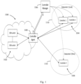
- a communication network 100 comprises a number of switches 102, in this example illustrated as SDN switches, and where a selection of switch controllers 104 are able to serve and control the switches 102 by performing logic switching operations remotely.
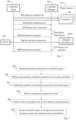
- a controller manager 106 is employed which basically selects and allocates appropriate switch controllers to serve the switches 102 by means of a controller agent 108, e.g. in a signaling procedure illustrated in Fig. 2 and as follows.
- the signaling procedure of Fig. 2 involves a switch 102, a set of (remote) switch controllers 104 located in one or more datacenters 110, one or more selected switch controllers 104A, a central controller manager 106 and a local controller agent 108.
- the controller agent 108 is referred to as a "local" controller agent implying that it serves switches located relatively close to the controller agent, e.g. by being in the same network 100 as the agent 108.
- the controller manager 106 is centralized in the sense that it can serve any local controller agents in different networks.
- the switch controllers 104 may be located anywhere, e.g. in data centers remote from the switches 102 such as one datacenter in Lund (Sweden) and another datacenter in Paris (France), as shown in Fig. 1 .
- Fig. 3 illustrates a procedure with actions performed in the controller manager 106, for enabling a switch 102 of a communication network to be controlled by a switch controller that performs logic switch operations.
- a first optional action 300 illustrates that the controller manager 106 may instruct a controller agent 108 to perform measurements related to connectivity to a set of switch controllers 104. These measurements are illustrated by an action 2:1 in Fig. 2 .
- An action 302 then illustrates that the controller manager 106 obtains from a controller agent 108, measurements related to connectivity to a set of switch controllers 104, as also shown in action 2:2 of Fig. 2 where the controller agent 108 reports the measurements of action 2:1 to the controller manager 106.
- the controller manager 106 may further determine how many switch controllers are required in each data center and then create/remove switch controllers accordingly, as indicated by another optional action 303.
- the controller manager 106 further receives a connection request for the switch 102 from the controller agent 108, as shown in action 304 and also in action 2:3 of Fig. 2 .
- the controller manager 106 selects at least one switch controller 104A in the set of switch controllers 104 based on the obtained measurements, to control said switch 102, as also shown in action 2:4 of Fig. 2 .
- This action 306 or 2:4 is performed in response to the connection request of action 304 or 2:3, respectively.
- selecting a switch controller to control said switch 102 is equivalent to allocating a switch controller to control the switch.
- the controller manager 106 instructs the controller agent 108 to set up or route a connection between the switch and the selected at least one switch controller, as also shown in action 2:5 of Fig. 2 .
- FIG. 4 Another example of how the solution is employed in terms of actions performed by a controller agent such as the controller agent 108, is further illustrated by the flow chart in Fig. 4 which will now be described likewise with further reference to Fig. 2 .
- the controller agent 108 performs the actions in Fig. 4 in conjunction with the actions in Fig. 3 performed by the controller manager 106, as indicated below.
- Fig. 4 thus illustrates a procedure in the controller agent 108 for enabling a switch 102 of a communication network 100 to be controlled by a switch controller 104A that performs logic switch operations.
- a first optional action 400 illustrates that the controller agent 108 may receive a measurement instruction from the controller manager 106, which corresponds to action 300.
- An action 402 illustrates that the controller agent 108 performs measurements related to connectivity to a set of switch controllers 104, as also shown in action 2:1 of Fig. 2 .
- the controller agent 108 reports said measurements related to connectivity to a controller manager 106, as also shown in action 2:2 of Fig. 2 which also corresponds to action 302.
- a further action 406 illustrates that if the controller agent 108 detects a connection from a switch 102, it sends a connection request for the switch 102 to the controller manager 106, as also shown in action 2:3 of Fig. 2 which also corresponds to action 304.
- the controller agent 108 receives from the controller manager 106 an instruction to set up or route a connection between the switch 102 and at least one switch controller 104A which has or have been selected based on the reported measurements related to connectivity, as also shown in action 2:5 of Fig. 2 .
- Action 408 corresponds to action 308.
- the controller agent 108 sets up or routes a connection between the switch 102 and the at least one switch controller 104A according to the instruction received in action 408, as also shown in action 2:6 of Fig. 2 .
- the controller manager 106 may further select a new switch controller in the set of switch controllers to serve the switch, as also shown in action 2:7 of Fig. 2 .
- This operation may be performed for at least one of the following reasons: 1) in case the previous switch controller becomes inactive or relocated, or 2) when the set of switch controllers need to be load balanced, or 3) when the new switch controller is instantiated/introduced.
- a final action 2:8 of Fig. 2 illustrates that the controller manager 106 sends another instruction to the controller agent 108, to set up or route a connection between the switch 102 and the new switch controller selected in action 2:7.
- the proposed solution allows the connections from switches to controllers be managed by an external partner.
- the controller manager 106 may instruct local controller agents to perform the above-described connectivity measurements and connect the switches to appropriate switch controllers.
- the controller agent 108 basically intercepts the connections from the switches and directs them to the correct switch controller 104A selected in action 306 or 2:4, e.g. based on rules than may have been configured.
- the controller agent 108 is able to perform or collect measurements on the link between the switch controllers and the switches. This information is sent to the controller manager 106 as a basis to make efficient decisions.
- the controller manager 106 may further control the creation/removal of controller instances 104 and may also apply access rules for admitting traffic to the switch controllers.
- the solution may be useful to solve or reduce at least some of the problems described above.
- One or more of the following advantages may thus be achieved:
- the controller manager 106 may obtain said measurements related to connectivity by instructing the controller agent 108, as shown in action 300, to perform the measurements.
- the obtained measurements may be related to at least one of: network latency, processing latency and throughput, and the controller manager 106 may in that case select the at least one switch controller with lowest latency and/or highest throughput.
- the obtained measurements may indicate connectivity to the switch controllers 104 themselves or to one or more data centers 110 where the switch controllers 104 are located.
- the controller manager 106 in action 306 selects the at least one switch controller in response to receiving a connection request for the switch from the controller agent, as in action 304 or 2:5.
- the controller manager 106 controls connection to the set of switch controllers 104 by sending connectivity rules to the controller agent 108, said connectivity rules determining to which one or more switch controllers the switch should be connected.
- the controller manager instructs the controller agent 108 in action 308 or 2:5 to set up or route a connection between the switch 102 and the selected at least one switch controller 104A, by, for example, sending an
- IP mapping of each switch controller to the controller agent 108 may be that said IP mapping indicates an IP address of the respective switch controller.
- the controller manager may, as in action 2:7 above, select a new switch controller in the set of switch controllers to serve the switch, 1) in case the previous switch controller becomes inactive or relocated, or 2) when the set of switch controllers need to be load balanced, or 3) when the new switch controller is instantiated/introduced.
- the communication network 100 may be a Software Defined Network, SDN.
- the controller agent 108 may perform the measurements related to connectivity in action 402 by measuring at least one of: a round trip delay between each switch controller 104 and the controller agent 108, a delay between a request and a following response from the respective switch controller 104, and the amount of traffic sent to/from the respective switch controllers 104.
- the measurements performed in action 402 may indicate connectivity to the switch controllers 104 themselves or to one or more data centers 110 where the switch controllers 104 are located. In another example embodiment, said measurements of connectivity may be performed in action 402 in response to receiving a measurement instruction from the controller manager 106, as of action 400.
- the controller agent 108 receives connectivity rules from the controller manager 106, said rules determining to which one or more switch controllers the switch should be connected.
- the controller agent 108 sends a connection request for the switch 102 to the controller manager, as of action 406 or 2:3.
- the instruction to set up or route a connection between the switch 102 and the at least one switch controller 104A, as received in action 408, may include an IP mapping of each switch controller 104.
- another example embodiment may be that said IP mapping indicates an IP address of the respective switch controller.
- the communication network 100 may be a Software Defined Network, SDN.
- the controller agent 108 may integrate or control a Network Address Translator, NAT, which translates the destination IP address in control traffic sent by the switch into an IP address of the respective switch controller.
- the controller agent 108 may integrate or control a Dynamic Host Configuration Protocol, DHCP, server (not shown) that configures the switch 102 with the IP address of the respective switch controller 104, 104A.
- NAT Network Address Translator
- DHCP Dynamic Host Configuration Protocol
- controller agent 108 may integrate or control a software defined network switch which the controller agent configures to translate the destination IP address in control traffic sent by the switch 102 into the IP address of the respective switch controller 104, 104A.
- FIG. 5 illustrates a detailed but non-limiting example of how a controller manager 500 and a controller agent 502, respectively, may be structured to bring about the above-described solution and embodiments thereof.
- the controller manager 500 and the controller agent 502 may be configured to operate according to any of the examples and embodiments of employing the solution as described herein, where appropriate.
- Each of the controller manager 500 and the controller agent 502 is shown to comprise a processor "P", a memory "M” and a communication circuit "C" with suitable equipment for transmitting and receiving radio signals in the manner described herein.
- the communication circuit C in each of the controller manager 500 and the controller agent 502 thus comprises equipment configured for communication with each other, and also with switch controllers and switches, respectively, using suitable protocols for the communication depending on the implementation.
- the solution is however not limited to any specific types of messages or protocols.
- the controller manager 500 is, e.g. by means of units, modules or the like, configured or arranged to perform at least some of the actions of the flow chart in Fig. 3 and as follows. Further, the controller agent 502 is, e.g. by means of units, modules or the like, configured or arranged to perform at least some of the actions of the flow chart in Fig. 4 and as follows.
- the controller manager 500 is arranged to enable a switch of a communication network to be controlled by a switch controller that performs logic switch operations.
- the controller manager 500 is configured to obtain from a controller agent 502, measurements related to connectivity to a set of switch controllers. This operation may be performed by an obtaining module 500A in the controller manager 500, as illustrated in action 302.
- the controller manager 500 is also configured to select at least one switch controller in the set of switch controllers based on the obtained measurements, to control said switch. This operation may be performed by an allocating module 500B in the controller manager 500, as illustrated in action 306.
- the allocating module 500B could alternatively be named a selecting module or a logic module.
- the controller manager 500 is further configured to instruct the controller agent 502 to set up or route a connection between the switch and the allocated/selected at least one switch controller. This operation may be performed by an instructing module 500C in the controller manager 500 as illustrated in action 308.
- the instructing module 500C could alternatively be named a sending module.
- the controller agent 502 is arranged to enable a switch of a communication network to be controlled by a switch controller that performs logic switch operations.
- the controller agent 502 is configured to perform measurements related to connectivity to a set of switch controllers. This operation may be performed by a measuring module 502A in the controller agent 502 as illustrated in action 402.
- the controller agent 502 is also configured to report said measurements related to connectivity to a controller manager 500. This operation may be performed by a reporting module 502B in the controller agent 502, as illustrated in action 404.
- the reporting module 502B could alternatively be named a sending module or unit.
- the controller agent 502 is further configured to receive from the controller manager 500 an instruction to set up or route a connection between the switch and at least one switch controller which has or have been allocated/selected based on the reported measurements related to connectivity. This operation may be performed by a receiving module 502C in the controller agent 502, as illustrated in action 408.
- the controller agent 502 is further configured to set up or route a connection between the switch and the at least one switch controller according to the received instruction. This operation may be performed by a connection module 502D in the controller agent 502, as illustrated in action 410.
- the connection module 502D could alternatively be named a routing module or unit.
- Fig. 5 illustrates various functional modules in the controller manager 500 and the controller agent 502, respectively, and the skilled person is able to implement these functional modules in practice using suitable software and hardware equipment.
- the solution is generally not limited to the shown structures of the controller manager 500 and the controller agent 502, and the functional modules therein may be configured to operate according to any of the features, examples and embodiments described in this disclosure, where appropriate.
- the functional modules 500A-C and 502A-D described above may be implemented in the controller manager 500 and the controller agent 502, respectively, by means of program modules of a respective computer program comprising code means which, when run by the processor P causes the controller manager 500 and the controller agent 502 to perform the above-described actions and procedures.
- Each processor P may comprise a single Central Processing Unit (CPU), or could comprise two or more processing units.
- each processor P may include a general purpose microprocessor, an instruction set processor and/or related chips sets and/or a special purpose microprocessor such as an Application Specific Integrated Circuit (ASIC).
- ASIC Application Specific Integrated Circuit
- Each processor P may also comprise a storage for caching purposes.
- Each computer program may be carried by a computer program product in each of the controller manager 500 and the controller agent 502 in the form of a memory having a computer readable medium and being connected to the processor P.
- the computer program product or memory M in each of the controller manager 500 and the controller agent 502 thus comprises a computer readable medium on which the computer program is stored e.g. in the form of computer program modules or the like.
- the memory M in each node may be a flash memory, a Random-Access Memory (RAM), a Read-Only Memory (ROM) or an Electrically Erasable Programmable ROM (EEPROM), and the program modules could in alternative embodiments be distributed on different computer program products in the form of memories within the respective controller manager 500 and controller agent 502.
- the solution described herein may be implemented in each of the controller manager 500 and the controller agent 502 by a computer program comprising instructions which, when executed on at least one processor, cause the at least one processor to carry out the actions according to any of the above embodiments and examples, where appropriate.
- the solution may also be implemented at each of the controller manager 500 and the controller agent 502 in a carrier containing the above computer program, wherein the carrier is one of an electronic signal, optical signal, radio signal, or computer readable storage medium.
- the solution may involve the following entities, using SDN terminology as an example:
- the Controller Agent may use two alternative methods for detecting the latency as follows.
- passive measurements indicate the real processing delay in switch controllers, it may be preferred to use passive measurements instead of active measurements (involving ping requests/replies). However, if the passive measurement is unavailable, e.g. because of the type of encryption, the Controller Agent may revert to the active measurement method.
- the Controller Agent receives from the Controller Manager a list of destinations to which it should test the latency.
- the Controller Agent after performing the measurements, sends the measurement results to the Controller Manager, which uses the results in selecting the nearest switch controller.
- the Controller Manager may maintain a database of the latencies between controller agents and data centers. To update the database, the Controller Manager may, for example periodically, request Controller Agents to perform latency measurements as described above.
- the Controller Manager may be responsible to set IP mappings in the controller agent.
- the controller manager can reactively set new IP mappings for new connections from the switch. In this approach, after receiving new connections from the switch, the controller agent will request the controller manager for new IP addresses.
- the controller manager can provide the Controller Agent with a pool of available switch controllers and the number of switches that can be connected to each of the switch controllers. The Controller Agent may thus have pre-calculated information about where to connect new switches.
- the Controller Agent could indicate to the Controller Manager once a switch has been connected to a switch controller. The Controller Manager can then update the pool of available switch controllers when it is close to depletion.
- the Controller Manager can create new Controller instances on demand if there are more requests for a switch controller than there are running instances available in the particular data center.
- the Controller Manager may also decide to reduce the number of Controller instances, which may require relocating some switches to another switch controller from the Controller instance to be removed.
- Fig. 6 shows a simplified signaling diagram that illustrates an example of how the embodiments herein may be employed in practice, involving a controller manager, a local controller agent, a switch and a set of switch controllers 1-3, which entities correspond to the controller manager 106, the controller agent 108, the switch 102 and the switch controllers 104, 104A, respectively, as shown in Figs 1 and 2 .
- the following steps 1-17 are executed:
- the Controller Agent either integrates a NAT or controls (e.g. via the Port Control Protocol, PCP, or Universal Plug And Play, UPNP) a NAT.
- switches may be configured with fixed pseudo addresses, i.e. IP addresses that do not correspond to any existing host but are routed outside the local network as they do not match any local network.
- the NAT sets up destination address translation based on the rules received from the Controller Manager.
- the translation tables in the NAT can then map each pseudo address to the currently configured IP address of the assigned controller.
- the Controller Agent either integrates a Dynamic Host Configuration Protocol, DHCP, server or controls a DHCP server.
- the DHCP server receives the Discover message from the switch and identifies the MAC address of the switch.
- the DHCP server replies (among the normal configuration information such as IP address and default gateway) with a Controller extension.
- the controller extension specifies the list of Controller addresses to which the switch should connect.
- the Controller Extension may be a new type of DHCP extension which could be useful in this context.
- the lease time should preferably be low to allow reconfiguration with a low delay; this causes the switch to renew its DHCP lease often with possibly new controller assignment. This particular example may require adaptation in the switch.
- the Controller Agent either integrates a OpenFlow switch or controls an OpenFlow switch (e.g. via OpenFlow).
- the Controller Agent may in this case create rules that modify the destination addresses similarly to the NAT case in the above example 1.
- Each data center hosting Controllers could be protected by a physical or virtualized firewall.
- the Controller Manager may then perform access control toward switch controllers such as SDN controllers through this firewall.
- access to Controllers running in an OpenStack based cloud could be controlled by defining rules in a Security Group. Each rule specifies which remote addresses and ports can access the Controller.
- OpenStack provides an API for remotely manipulating security groups. Rules could be defined so that the public address of the Controller Agent (or the public address of the NAT/switch controller by the Controller Agent, depending on used implementation) can access the Controller, with all other access denied as a default rule.
- the Controller Manager and the switch Controllers may be implemented in resources of a cloud environment, often referred to as "the cloud". In that case, switch Controllers could be distributed between several locations (e.g. in different data centers) in order to reduce latency.
- the Controller Manager can instantiate new switch Controllers on demand.
- the embodiments herein may be used to implement a cloud service where switch Controllers are provided as an external service.
- the Controller Agent could preferably be located in the same site as the Switches.
- the embodiments herein may introduce local controller agents which allow to find connections with low latency and connect local switches to remote switch controllers in an efficient manner.
- the local controller agent can continuously measure the processing latency in controller nodes and report the results to the centralized controller manager which then can optimize the selection and allocation of switch controllers.
- the controller agent enables third-party controller providers to control the connectivity of switches in a local network without having direct access to the local network. While the solution has been described with reference to specific exemplifying embodiments, the description is generally only intended to illustrate the inventive concept and should not be taken as limiting the scope of the solution.
- controller manager controller agent
- switch switch controller
- connectivity connectivity rules
Landscapes
- Engineering & Computer Science (AREA)
- Computer Networks & Wireless Communication (AREA)
- Signal Processing (AREA)
- Environmental & Geological Engineering (AREA)
- Health & Medical Sciences (AREA)
- Cardiology (AREA)
- General Health & Medical Sciences (AREA)
- Data Exchanges In Wide-Area Networks (AREA)
Claims (17)
- Verfahren, das von einem Steuerungsmanager (106) durchgeführt wird, der sich außerhalb eines Kommunikationsnetzwerks (100) befindet, zum Ermöglichen, dass ein Switch (102) des Kommunikationsnetzwerks (100) durch eine Switch-Steuerung gesteuert wird, die logische Switch-Operationen durchführt, wobei die Switch-Steuerung zu einem Satz von Switch-Steuerungen gehört, und das Verfahren umfasst:- Erhalten (2:2, 302) von Messungen in Bezug auf Konnektivität zum Satz von Switch-Steuerungen (104) von einem lokalen Steuerungsagenten (108),- Auswählen (2:4, 306) mindestes einer Switch-Steuerung (104A) zum Steuern des Switchs in dem Satz von Switch-Steuerungen basierend auf den erhaltenen Messungen in Reaktion auf ein Empfangen (2:3, 304) einer Verbindungsanforderung für den Switch vom lokalen Steuerungsagenten (104A), und- Anweisen (2:5, 308) des lokalen Steuerungsagenten zum Aufbauen einer Verbindung zwischen dem Switch und der ausgewählten mindestens einen Switch-Steuerung durch Senden von Konnektivitätsregeln an den lokalen Steuerungsagenten, wobei die Konnektivitätsregeln bestimmen, mit welcher der einen oder mehreren Switch-Steuerungen der Switch verbunden werden sollte.
- Verfahren nach Anspruch 1, wobei die Messungen in Bezug auf Konnektivität durch Anweisen (300) des lokalen Steuerungsagenten zum Durchführen der Messungen erhalten werden.
- Verfahren nach einem der Ansprüche 1 bis 2, wobei das Anweisen (2:5, 308) des lokalen Steuerungsagenten zum Aufbauen einer Verbindung zwischen dem Switch und der ausgewählten mindestens einen Switch-Steuerung durch Senden von Konnektivitätsregeln an den lokalen Steuerungsagenten ein Senden einer IP-Zuordnung jeder Switch-Steuerung an den Steuerungsagenten umfasst.
- Verfahren nach einem der Ansprüche 1 bis 3, wobei das Kommunikationsnetzwerk ein softwaredefiniertes Netzwerk, SDN, ist.
- Steuerungsmanager (500), der dazu ausgelegt ist, zu ermöglichen, dass ein Switch eines Kommunikationsnetzwerks durch eine Switch-Steuerung gesteuert wird, die logische Switch-Operationen durchführt, wobei die Switch-Steuerung zu einem Satz von Switch-Steuerungen gehört, wobei sich der Steuerungsmanager (500) außerhalb des Netzwerks befindet und konfiguriert ist zum:- Erhalten (500A) von Messungen in Bezug auf Konnektivität zum Satz von Switch-Steuerungen von einem lokalen Steuerungsagenten (502),- Auswählen (500B) mindestes einer Switch-Steuerung zum Steuern des Switchs im Satz von Switch-Steuerungen basierend auf den erhaltenen Messungen in Reaktion auf ein Empfangen (2:3, 304) einer Verbindungsanforderung für den Switch vom lokalen Steuerungsagenten (502), und- Anweisen (500C) des lokalen Steuerungsagenten zum Aufbauen einer Verbindung zwischen dem Switch und der ausgewählten mindestens einen Switch-Steuerung durch Senden von Konnektivitätsregeln an den lokalen Steuerungsagenten, wobei die Konnektivitätsregeln bestimmen, mit welcher der einen oder mehreren Switch-Steuerungen der Switch verbunden werden sollte.
- Steuerungsmanager (500) nach Anspruch 5, wobei der Steuerungsmanager (500) zum Erhalten der Messungen in Bezug auf Konnektivität durch Anweisen des lokalen Steuerungsagenten zum Durchführen der Messungen konfiguriert ist.
- Steuerungsmanager (500) nach Anspruch 5 bis 6, wobei die erhaltenen Messungen mit mindestens einem von Folgenden in Beziehung stehen: Netzwerklatenz, Verarbeitungslatenz und Durchsatz, und der Steuerungsmanager (500) zum Auswählen der mindestens einen Switch-Steuerung mit der niedrigsten Latenz und/oder dem höchsten Durchsatz konfiguriert ist.
- Steuerungsmanager (500) nach einem der Ansprüche 5 bis 7, wobei die erhaltenen Messungen Konnektivität zu den Switch-Steuerungen selbst oder zu einem oder mehreren Rechenzentren angeben, in welchen sich die Switch-Steuerungen befinden.
- Steuerungsmanager (500) nach einem der Ansprüche 5 bis 8, wobei der Steuerungsmanager (500) so konfiguriert ist, dass er eine neue Switch-Steuerung im Satz von Switch-Steuerungen zum Bedienen des Switchs auswählt, 1) falls die vorherige Switch-Steuerung inaktiv oder verlegt wird oder 2) wenn Lastausgleich des Satzes von Switch-Steuerungen erforderlich ist oder 3) wenn die neue Switch-Steuerung instanziiert/eingeführt wird.
- Verfahren, das von einem lokalen Steuerungsagenten (108) durchgeführt wird, zum Ermöglichen, dass ein Switch (102) des Kommunikationsnetzwerks (100) durch eine Switch-Steuerung gesteuert wird, die logische Switch-Operationen durchführt, wobei die Switch-Steuerung zu einem Satz von Switch-Steuerungen gehört, und das Verfahren umfasst:- Durchführen (2:1, 402) von Messungen in Bezug auf Konnektivität zum Satz von Switch-Steuerungen (104),- Melden (2:2, 404) der Messungen in Bezug auf Konnektivität an einen Steuerungsmanager (106), der sich außerhalb des Netzwerks befindet,- Senden (2:3, 406) einer Verbindungsanforderung für den Switch (102) an den Steuerungsmanager,- Empfangen (2:5, 408) einer Anweisung vom Steuerungsmanager zum Aufbauen einer Verbindung zwischen dem Switch und mindestens einer Switch-Steuerung (104A), die basierend auf den gemeldeten Messungen in Bezug auf Konnektivität ausgewählt wurde(n), durch Empfangen von Konnektivitätsregeln, wobei die Konnektivitätsregeln bestimmen, mit welcher der einen oder mehreren Switch-Steuerungen der Switch verbunden werden sollte, und- Aufbauen (2:6, 410) einer Verbindung zwischen dem Switch und der mindestens einen Switch-Steuerung gemäß der empfangenen Anweisung.
- Verfahren nach Anspruch 10, wobei die Messungen in Bezug auf Konnektivität durchgeführt werden, indem mindestens eines gemessen wird von: einer Umlaufzeitverzögerung zwischen jeder Switch-Steuerung und dem lokalen Steuerungsagenten, einer Verzögerung zwischen einer Anforderung und einer folgenden Antwort von der jeweiligen Switch-Steuerung und der Menge von Verkehr, die von den/an die jeweiligen Switch-Steuerungen gesendet wird.
- Verfahren nach einem der Ansprüche 10 bis 11, wobei die empfangene Anweisungen zum Aufbauen oder Routen einer Verbindung zwischen dem Switch und der mindestens einen Switch-Steuerung durch Empfangen von Konnektivitätsregeln eine IP-Zuordnung jeder Switch-Steuerung umfasst.
- Lokaler Steuerungsagent (502), der dazu ausgelegt ist, zu ermöglichen, dass ein Switch eines Kommunikationsnetzwerks durch eine Switch-Steuerung gesteuert wird, die logische Switch-Operationen durchführt, wobei die Switch-Steuerung zu einem Satz von Switch-Steuerungen gehört, wobei der lokale Steuerungsagent (502) konfiguriert ist zum:- Durchführen (502A) von Messungen in Bezug auf Konnektivität zum Satz von Switch-Steuerungen in Reaktion auf ein Empfangen einer Messanweisung von einem Steuerungsmanager (500), der sich außerhalb des Netzwerks befindet,- Melden (502B) der Messungen in Bezug auf Konnektivität an einen Steuerungsmanager (500),- Senden einer Verbindungsanforderung für den Switch an den Steuerungsmanager,- Empfangen (502C) einer Anweisung vom Steuerungsmanager zum Aufbauen einer Verbindung zwischen dem Switch und mindestens einer Switch-Steuerung, die basierend auf den gemeldeten Messungen in Bezug auf Konnektivität ausgewählt wurde(n), durch Empfangen von Konnektivitätsregeln, wobei die Konnektivitätsregeln bestimmen, mit welcher der einen oder mehreren Switch-Steuerungen der Switch verbunden werden sollte, und- Aufbauen (502D) einer Verbindung zwischen dem Switch und der mindestens einen Switch-Steuerung gemäß der empfangenen Anweisung.
- Lokaler Steuerungsagent (502) nach Anspruch 13, wobei der lokale Steuerungsagent (502) so konfiguriert ist, dass er die Messungen in Bezug auf Konnektivität durchführt, indem er mindestens eines misst von: einer Umlaufzeitverzögerung zwischen jeder Switch-Steuerung und dem lokalen Steuerungsagenten, einer Verzögerung zwischen einer Anforderung und einer folgenden Antwort von der jeweiligen Switch-Steuerung und der Menge von Verkehr, die von den/an die jeweiligen Switch-Steuerungen gesendet wird.
- Lokaler Steuerungsagent (502) nach einem der Ansprüche 13 bis 14, wobei die durchgeführten Messungen Konnektivität zu den Switch-Steuerungen selbst oder zu einem oder mehreren Rechenzentren angeben, in welchen sich die Switch-Steuerungen befinden.
- Lokaler Steuerungsagent (502) nach einem der Ansprüche 13 bis 15, wobei der Steuerungsagent (502) so konfiguriert ist, dass er einen Netzwerkadressübersetzer, NAT, integriert oder steuert, der die Ziel-IP-Adresse in Steuerungsverkehr, der vom Switch gesendet wird, in eine IP-Adresse der jeweiligen Switch-Steuerung übersetzt.
- Lokaler Steuerungsagent (502) nach einem der Ansprüche 13 bis 16, wobei der Steuerungsagent (502) so konfiguriert ist, dass er einen Switch eines softwaredefinierten Netzwerks integriert oder steuert, den der Steuerungsagent zum Übersetzen der Ziel-IP-Adresse in Steuerungsverkehr, der vom Switch gesendet wird, in eine IP-Adresse der jeweiligen Switch-Steuerung konfiguriert.
Applications Claiming Priority (2)
| Application Number | Priority Date | Filing Date | Title |
|---|---|---|---|
| US201762577731P | 2017-10-27 | 2017-10-27 | |
| PCT/EP2018/077279 WO2019081188A1 (en) | 2017-10-27 | 2018-10-08 | METHODS, CONTROLLER MANAGER AND CONTROLLER AGENT FOR CONNECTION BETWEEN A SWITCH OF A COMMUNICATION NETWORK AND A SWITCH CONTROLLER |
Publications (2)
| Publication Number | Publication Date |
|---|---|
| EP3701682A1 EP3701682A1 (de) | 2020-09-02 |
| EP3701682B1 true EP3701682B1 (de) | 2024-01-17 |
Family
ID=63832410
Family Applications (1)
| Application Number | Title | Priority Date | Filing Date |
|---|---|---|---|
| EP18785324.7A Active EP3701682B1 (de) | 2017-10-27 | 2018-10-08 | Verfahren, steuerungsmanager und steuermittel zum ermöglichen einer verbindung zwischen einem schalter eines kommunikationsnetzes und eines schaltreglers |
Country Status (3)
| Country | Link |
|---|---|
| US (1) | US11316739B2 (de) |
| EP (1) | EP3701682B1 (de) |
| WO (1) | WO2019081188A1 (de) |
Families Citing this family (6)
| Publication number | Priority date | Publication date | Assignee | Title |
|---|---|---|---|---|
| US11297131B2 (en) * | 2019-12-10 | 2022-04-05 | Oracle International Corporation | Method and apparatus for multi-vendor GTM fabric |
| US11575572B2 (en) | 2021-04-13 | 2023-02-07 | Juniper Networks, Inc. | Network controller horizontal scaling for network device configuration sessions management |
| CN115208748B (zh) * | 2021-04-13 | 2024-10-01 | 瞻博网络公司 | 用于网络设备配置会话管理的网络控制器水平缩放 |
| US11956115B2 (en) * | 2021-12-09 | 2024-04-09 | MetalSoft Cloud, Inc. | Distributed control system for large scale geographically distributed data centers and methods for use therewith |
| CN115277424B (zh) * | 2022-06-23 | 2023-10-03 | 中国联合网络通信集团有限公司 | 软件定义网络中的决策下发方法、装置及存储介质 |
| US12238006B1 (en) | 2023-08-25 | 2025-02-25 | Cisco Technology, Inc. | Self-healing SD-WAN controllers and networks |
Family Cites Families (5)
| Publication number | Priority date | Publication date | Assignee | Title |
|---|---|---|---|---|
| US9461923B2 (en) * | 2013-12-06 | 2016-10-04 | Algoblu Holdings Limited | Performance-based routing in software-defined network (SDN) |
| US10148496B2 (en) * | 2015-05-05 | 2018-12-04 | Citrix Systems, Inc. | Systems and methods for configuring a device via a software-defined networking controller |
| JP2016219859A (ja) * | 2015-05-14 | 2016-12-22 | 富士通株式会社 | コントローラ、コントローラの制御装置、及び、制御方法 |
| WO2018108246A1 (en) * | 2016-12-13 | 2018-06-21 | NEC Laboratories Europe GmbH | Method and software defined network controller for performing round-trip time determination between a source element and a target element |
| US10397124B2 (en) * | 2017-01-17 | 2019-08-27 | Argela Yazilim ve Bilisim Teknolojileri San. ve Tic. A.S. | System and method to prevent persistent full switch queues in software defined networks |
-
2018
- 2018-10-08 US US16/759,446 patent/US11316739B2/en not_active Expired - Fee Related
- 2018-10-08 EP EP18785324.7A patent/EP3701682B1/de active Active
- 2018-10-08 WO PCT/EP2018/077279 patent/WO2019081188A1/en not_active Ceased
Also Published As
| Publication number | Publication date |
|---|---|
| WO2019081188A1 (en) | 2019-05-02 |
| US11316739B2 (en) | 2022-04-26 |
| US20200295998A1 (en) | 2020-09-17 |
| EP3701682A1 (de) | 2020-09-02 |
Similar Documents
| Publication | Publication Date | Title |
|---|---|---|
| US11316739B2 (en) | Methods, controller manager and controller agent for enabling a connection between a switch of a communication network and a switch controller | |
| US10819678B2 (en) | Data network address sharing between multiple elements associated with a shared network interface unit | |
| US11785078B1 (en) | Multi-cloud active mesh network system and method | |
| US11038834B2 (en) | Selecting an external link of a plurality of external links | |
| EP3694145B1 (de) | Verfahren und vorrichtung zum senden von nachrichten | |
| CN101884208B (zh) | 在多个适配器间同时支持多个虚拟ip地址的主机中的故障转移 | |
| EP3028438B1 (de) | Konfiguration von weiterleitungsregeln unter verwendung von adressauflösungsprotokoll | |
| WO2015150756A1 (en) | Data center networks | |
| US11621917B2 (en) | Transparent multiplexing of IP endpoints | |
| EP3529953A1 (de) | Elastisches vpn zur überbrückung von entfernten inseln | |
| US12425327B2 (en) | Configuring application availability using anycast addressing | |
| KR20000076845A (ko) | Ip 데이터 전송 시스템의 다중 arp 기능 | |
| EP3552370A1 (de) | Implementierung von servicefunktionsketten | |
| CN112997509B (zh) | 用于在信号传送点(stp)消息处理器之间分配sigtran连接的方法、系统和计算机可读介质 | |
| JP2011120083A (ja) | マルチホーム接続環境における経路切替方法、ルータ及びプログラム | |
| WO2022147152A1 (en) | Management network and method of operation | |
| US20250373541A1 (en) | High-performance communication link and method of operation | |
| JP6360012B2 (ja) | ネットワーク統合システムおよびネットワーク統合方法 | |
| US20200274799A1 (en) | Multi-vrf and multi-service insertion on edge gateway virtual machines | |
| KR102763960B1 (ko) | 사용자 정의 기반의 가상 네트워크 설정 방법 | |
| CA2736956C (en) | Network management system using management addresses | |
| US8732335B2 (en) | Device communications over unnumbered interfaces | |
| US20200389427A1 (en) | Loopback address configuration | |
| GB2559660B (en) | Implementing service function chains | |
| KR20240007787A (ko) | 엣지 플랫폼의 l2 관리를 지원하는 엣지 플랫폼 관리 장치 및 이의 운용 방법 |
Legal Events
| Date | Code | Title | Description |
|---|---|---|---|
| STAA | Information on the status of an ep patent application or granted ep patent |
Free format text: STATUS: UNKNOWN |
|
| STAA | Information on the status of an ep patent application or granted ep patent |
Free format text: STATUS: THE INTERNATIONAL PUBLICATION HAS BEEN MADE |
|
| PUAI | Public reference made under article 153(3) epc to a published international application that has entered the european phase |
Free format text: ORIGINAL CODE: 0009012 |
|
| STAA | Information on the status of an ep patent application or granted ep patent |
Free format text: STATUS: REQUEST FOR EXAMINATION WAS MADE |
|
| 17P | Request for examination filed |
Effective date: 20200427 |
|
| AK | Designated contracting states |
Kind code of ref document: A1 Designated state(s): AL AT BE BG CH CY CZ DE DK EE ES FI FR GB GR HR HU IE IS IT LI LT LU LV MC MK MT NL NO PL PT RO RS SE SI SK SM TR |
|
| AX | Request for extension of the european patent |
Extension state: BA ME |
|
| STAA | Information on the status of an ep patent application or granted ep patent |
Free format text: STATUS: EXAMINATION IS IN PROGRESS |
|
| 17Q | First examination report despatched |
Effective date: 20201117 |
|
| DAV | Request for validation of the european patent (deleted) | ||
| DAX | Request for extension of the european patent (deleted) | ||
| REG | Reference to a national code |
Ref country code: DE Ref legal event code: R079 Free format text: PREVIOUS MAIN CLASS: H04L0012260000 Ipc: H04L0043080000 Ref country code: DE Ref legal event code: R079 Ref document number: 602018064274 Country of ref document: DE Free format text: PREVIOUS MAIN CLASS: H04L0012260000 Ipc: H04L0043080000 |
|
| GRAP | Despatch of communication of intention to grant a patent |
Free format text: ORIGINAL CODE: EPIDOSNIGR1 |
|
| STAA | Information on the status of an ep patent application or granted ep patent |
Free format text: STATUS: GRANT OF PATENT IS INTENDED |
|
| RIC1 | Information provided on ipc code assigned before grant |
Ipc: H04L 43/20 20220101ALI20230920BHEP Ipc: H04L 41/40 20220101ALI20230920BHEP Ipc: H04L 41/122 20220101ALI20230920BHEP Ipc: H04L 41/0897 20220101ALI20230920BHEP Ipc: H04L 43/10 20220101ALI20230920BHEP Ipc: H04L 41/0816 20220101ALI20230920BHEP Ipc: H04L 43/08 20220101AFI20230920BHEP |
|
| INTG | Intention to grant announced |
Effective date: 20231004 |
|
| GRAS | Grant fee paid |
Free format text: ORIGINAL CODE: EPIDOSNIGR3 |
|
| GRAA | (expected) grant |
Free format text: ORIGINAL CODE: 0009210 |
|
| STAA | Information on the status of an ep patent application or granted ep patent |
Free format text: STATUS: THE PATENT HAS BEEN GRANTED |
|
| AK | Designated contracting states |
Kind code of ref document: B1 Designated state(s): AL AT BE BG CH CY CZ DE DK EE ES FI FR GB GR HR HU IE IS IT LI LT LU LV MC MK MT NL NO PL PT RO RS SE SI SK SM TR |
|
| REG | Reference to a national code |
Ref country code: GB Ref legal event code: FG4D |
|
| REG | Reference to a national code |
Ref country code: CH Ref legal event code: EP |
|
| REG | Reference to a national code |
Ref country code: DE Ref legal event code: R096 Ref document number: 602018064274 Country of ref document: DE |
|
| REG | Reference to a national code |
Ref country code: IE Ref legal event code: FG4D |
|
| REG | Reference to a national code |
Ref country code: LT Ref legal event code: MG9D |
|
| REG | Reference to a national code |
Ref country code: NL Ref legal event code: MP Effective date: 20240117 |
|
| REG | Reference to a national code |
Ref country code: AT Ref legal event code: MK05 Ref document number: 1651263 Country of ref document: AT Kind code of ref document: T Effective date: 20240117 |
|
| PG25 | Lapsed in a contracting state [announced via postgrant information from national office to epo] |
Ref country code: NL Free format text: LAPSE BECAUSE OF FAILURE TO SUBMIT A TRANSLATION OF THE DESCRIPTION OR TO PAY THE FEE WITHIN THE PRESCRIBED TIME-LIMIT Effective date: 20240117 |
|
| PG25 | Lapsed in a contracting state [announced via postgrant information from national office to epo] |
Ref country code: NL Free format text: LAPSE BECAUSE OF FAILURE TO SUBMIT A TRANSLATION OF THE DESCRIPTION OR TO PAY THE FEE WITHIN THE PRESCRIBED TIME-LIMIT Effective date: 20240117 |
|
| PG25 | Lapsed in a contracting state [announced via postgrant information from national office to epo] |
Ref country code: IS Free format text: LAPSE BECAUSE OF FAILURE TO SUBMIT A TRANSLATION OF THE DESCRIPTION OR TO PAY THE FEE WITHIN THE PRESCRIBED TIME-LIMIT Effective date: 20240517 |
|
| PG25 | Lapsed in a contracting state [announced via postgrant information from national office to epo] |
Ref country code: LT Free format text: LAPSE BECAUSE OF FAILURE TO SUBMIT A TRANSLATION OF THE DESCRIPTION OR TO PAY THE FEE WITHIN THE PRESCRIBED TIME-LIMIT Effective date: 20240117 |
|
| PG25 | Lapsed in a contracting state [announced via postgrant information from national office to epo] |
Ref country code: GR Free format text: LAPSE BECAUSE OF FAILURE TO SUBMIT A TRANSLATION OF THE DESCRIPTION OR TO PAY THE FEE WITHIN THE PRESCRIBED TIME-LIMIT Effective date: 20240418 |
|
| PG25 | Lapsed in a contracting state [announced via postgrant information from national office to epo] |
Ref country code: RS Free format text: LAPSE BECAUSE OF FAILURE TO SUBMIT A TRANSLATION OF THE DESCRIPTION OR TO PAY THE FEE WITHIN THE PRESCRIBED TIME-LIMIT Effective date: 20240417 Ref country code: HR Free format text: LAPSE BECAUSE OF FAILURE TO SUBMIT A TRANSLATION OF THE DESCRIPTION OR TO PAY THE FEE WITHIN THE PRESCRIBED TIME-LIMIT Effective date: 20240117 |
|
| PG25 | Lapsed in a contracting state [announced via postgrant information from national office to epo] |
Ref country code: ES Free format text: LAPSE BECAUSE OF FAILURE TO SUBMIT A TRANSLATION OF THE DESCRIPTION OR TO PAY THE FEE WITHIN THE PRESCRIBED TIME-LIMIT Effective date: 20240117 |
|
| PG25 | Lapsed in a contracting state [announced via postgrant information from national office to epo] |
Ref country code: AT Free format text: LAPSE BECAUSE OF FAILURE TO SUBMIT A TRANSLATION OF THE DESCRIPTION OR TO PAY THE FEE WITHIN THE PRESCRIBED TIME-LIMIT Effective date: 20240117 |
|
| PG25 | Lapsed in a contracting state [announced via postgrant information from national office to epo] |
Ref country code: RS Free format text: LAPSE BECAUSE OF FAILURE TO SUBMIT A TRANSLATION OF THE DESCRIPTION OR TO PAY THE FEE WITHIN THE PRESCRIBED TIME-LIMIT Effective date: 20240417 Ref country code: NO Free format text: LAPSE BECAUSE OF FAILURE TO SUBMIT A TRANSLATION OF THE DESCRIPTION OR TO PAY THE FEE WITHIN THE PRESCRIBED TIME-LIMIT Effective date: 20240417 Ref country code: LT Free format text: LAPSE BECAUSE OF FAILURE TO SUBMIT A TRANSLATION OF THE DESCRIPTION OR TO PAY THE FEE WITHIN THE PRESCRIBED TIME-LIMIT Effective date: 20240117 Ref country code: IS Free format text: LAPSE BECAUSE OF FAILURE TO SUBMIT A TRANSLATION OF THE DESCRIPTION OR TO PAY THE FEE WITHIN THE PRESCRIBED TIME-LIMIT Effective date: 20240517 Ref country code: HR Free format text: LAPSE BECAUSE OF FAILURE TO SUBMIT A TRANSLATION OF THE DESCRIPTION OR TO PAY THE FEE WITHIN THE PRESCRIBED TIME-LIMIT Effective date: 20240117 Ref country code: GR Free format text: LAPSE BECAUSE OF FAILURE TO SUBMIT A TRANSLATION OF THE DESCRIPTION OR TO PAY THE FEE WITHIN THE PRESCRIBED TIME-LIMIT Effective date: 20240418 Ref country code: FI Free format text: LAPSE BECAUSE OF FAILURE TO SUBMIT A TRANSLATION OF THE DESCRIPTION OR TO PAY THE FEE WITHIN THE PRESCRIBED TIME-LIMIT Effective date: 20240117 Ref country code: ES Free format text: LAPSE BECAUSE OF FAILURE TO SUBMIT A TRANSLATION OF THE DESCRIPTION OR TO PAY THE FEE WITHIN THE PRESCRIBED TIME-LIMIT Effective date: 20240117 Ref country code: BG Free format text: LAPSE BECAUSE OF FAILURE TO SUBMIT A TRANSLATION OF THE DESCRIPTION OR TO PAY THE FEE WITHIN THE PRESCRIBED TIME-LIMIT Effective date: 20240117 Ref country code: AT Free format text: LAPSE BECAUSE OF FAILURE TO SUBMIT A TRANSLATION OF THE DESCRIPTION OR TO PAY THE FEE WITHIN THE PRESCRIBED TIME-LIMIT Effective date: 20240117 |
|
| PG25 | Lapsed in a contracting state [announced via postgrant information from national office to epo] |
Ref country code: PT Free format text: LAPSE BECAUSE OF FAILURE TO SUBMIT A TRANSLATION OF THE DESCRIPTION OR TO PAY THE FEE WITHIN THE PRESCRIBED TIME-LIMIT Effective date: 20240517 Ref country code: PL Free format text: LAPSE BECAUSE OF FAILURE TO SUBMIT A TRANSLATION OF THE DESCRIPTION OR TO PAY THE FEE WITHIN THE PRESCRIBED TIME-LIMIT Effective date: 20240117 |
|
| PG25 | Lapsed in a contracting state [announced via postgrant information from national office to epo] |
Ref country code: SE Free format text: LAPSE BECAUSE OF FAILURE TO SUBMIT A TRANSLATION OF THE DESCRIPTION OR TO PAY THE FEE WITHIN THE PRESCRIBED TIME-LIMIT Effective date: 20240117 Ref country code: PT Free format text: LAPSE BECAUSE OF FAILURE TO SUBMIT A TRANSLATION OF THE DESCRIPTION OR TO PAY THE FEE WITHIN THE PRESCRIBED TIME-LIMIT Effective date: 20240517 Ref country code: PL Free format text: LAPSE BECAUSE OF FAILURE TO SUBMIT A TRANSLATION OF THE DESCRIPTION OR TO PAY THE FEE WITHIN THE PRESCRIBED TIME-LIMIT Effective date: 20240117 Ref country code: LV Free format text: LAPSE BECAUSE OF FAILURE TO SUBMIT A TRANSLATION OF THE DESCRIPTION OR TO PAY THE FEE WITHIN THE PRESCRIBED TIME-LIMIT Effective date: 20240117 |
|
| PG25 | Lapsed in a contracting state [announced via postgrant information from national office to epo] |
Ref country code: DK Free format text: LAPSE BECAUSE OF FAILURE TO SUBMIT A TRANSLATION OF THE DESCRIPTION OR TO PAY THE FEE WITHIN THE PRESCRIBED TIME-LIMIT Effective date: 20240117 |
|
| PG25 | Lapsed in a contracting state [announced via postgrant information from national office to epo] |
Ref country code: SM Free format text: LAPSE BECAUSE OF FAILURE TO SUBMIT A TRANSLATION OF THE DESCRIPTION OR TO PAY THE FEE WITHIN THE PRESCRIBED TIME-LIMIT Effective date: 20240117 |
|
| REG | Reference to a national code |
Ref country code: DE Ref legal event code: R097 Ref document number: 602018064274 Country of ref document: DE |
|
| PG25 | Lapsed in a contracting state [announced via postgrant information from national office to epo] |
Ref country code: EE Free format text: LAPSE BECAUSE OF FAILURE TO SUBMIT A TRANSLATION OF THE DESCRIPTION OR TO PAY THE FEE WITHIN THE PRESCRIBED TIME-LIMIT Effective date: 20240117 Ref country code: CZ Free format text: LAPSE BECAUSE OF FAILURE TO SUBMIT A TRANSLATION OF THE DESCRIPTION OR TO PAY THE FEE WITHIN THE PRESCRIBED TIME-LIMIT Effective date: 20240117 |
|
| PG25 | Lapsed in a contracting state [announced via postgrant information from national office to epo] |
Ref country code: SK Free format text: LAPSE BECAUSE OF FAILURE TO SUBMIT A TRANSLATION OF THE DESCRIPTION OR TO PAY THE FEE WITHIN THE PRESCRIBED TIME-LIMIT Effective date: 20240117 |
|
| PG25 | Lapsed in a contracting state [announced via postgrant information from national office to epo] |
Ref country code: SM Free format text: LAPSE BECAUSE OF FAILURE TO SUBMIT A TRANSLATION OF THE DESCRIPTION OR TO PAY THE FEE WITHIN THE PRESCRIBED TIME-LIMIT Effective date: 20240117 Ref country code: SK Free format text: LAPSE BECAUSE OF FAILURE TO SUBMIT A TRANSLATION OF THE DESCRIPTION OR TO PAY THE FEE WITHIN THE PRESCRIBED TIME-LIMIT Effective date: 20240117 Ref country code: RO Free format text: LAPSE BECAUSE OF FAILURE TO SUBMIT A TRANSLATION OF THE DESCRIPTION OR TO PAY THE FEE WITHIN THE PRESCRIBED TIME-LIMIT Effective date: 20240117 Ref country code: EE Free format text: LAPSE BECAUSE OF FAILURE TO SUBMIT A TRANSLATION OF THE DESCRIPTION OR TO PAY THE FEE WITHIN THE PRESCRIBED TIME-LIMIT Effective date: 20240117 Ref country code: DK Free format text: LAPSE BECAUSE OF FAILURE TO SUBMIT A TRANSLATION OF THE DESCRIPTION OR TO PAY THE FEE WITHIN THE PRESCRIBED TIME-LIMIT Effective date: 20240117 Ref country code: CZ Free format text: LAPSE BECAUSE OF FAILURE TO SUBMIT A TRANSLATION OF THE DESCRIPTION OR TO PAY THE FEE WITHIN THE PRESCRIBED TIME-LIMIT Effective date: 20240117 |
|
| PLBE | No opposition filed within time limit |
Free format text: ORIGINAL CODE: 0009261 |
|
| STAA | Information on the status of an ep patent application or granted ep patent |
Free format text: STATUS: NO OPPOSITION FILED WITHIN TIME LIMIT |
|
| PG25 | Lapsed in a contracting state [announced via postgrant information from national office to epo] |
Ref country code: IT Free format text: LAPSE BECAUSE OF FAILURE TO SUBMIT A TRANSLATION OF THE DESCRIPTION OR TO PAY THE FEE WITHIN THE PRESCRIBED TIME-LIMIT Effective date: 20240117 |
|
| 26N | No opposition filed |
Effective date: 20241018 |
|
| PG25 | Lapsed in a contracting state [announced via postgrant information from national office to epo] |
Ref country code: IT Free format text: LAPSE BECAUSE OF FAILURE TO SUBMIT A TRANSLATION OF THE DESCRIPTION OR TO PAY THE FEE WITHIN THE PRESCRIBED TIME-LIMIT Effective date: 20240117 |
|
| PG25 | Lapsed in a contracting state [announced via postgrant information from national office to epo] |
Ref country code: SI Free format text: LAPSE BECAUSE OF FAILURE TO SUBMIT A TRANSLATION OF THE DESCRIPTION OR TO PAY THE FEE WITHIN THE PRESCRIBED TIME-LIMIT Effective date: 20240117 |
|
| REG | Reference to a national code |
Ref country code: DE Ref legal event code: R119 Ref document number: 602018064274 Country of ref document: DE |
|
| REG | Reference to a national code |
Ref country code: CH Ref legal event code: PL |
|
| GBPC | Gb: european patent ceased through non-payment of renewal fee |
Effective date: 20241008 |
|
| PG25 | Lapsed in a contracting state [announced via postgrant information from national office to epo] |
Ref country code: MC Free format text: LAPSE BECAUSE OF FAILURE TO SUBMIT A TRANSLATION OF THE DESCRIPTION OR TO PAY THE FEE WITHIN THE PRESCRIBED TIME-LIMIT Effective date: 20240117 |
|
| PG25 | Lapsed in a contracting state [announced via postgrant information from national office to epo] |
Ref country code: DE Free format text: LAPSE BECAUSE OF NON-PAYMENT OF DUE FEES Effective date: 20250501 |
|
| PG25 | Lapsed in a contracting state [announced via postgrant information from national office to epo] |
Ref country code: GB Free format text: LAPSE BECAUSE OF NON-PAYMENT OF DUE FEES Effective date: 20241008 |
|
| PG25 | Lapsed in a contracting state [announced via postgrant information from national office to epo] |
Ref country code: LU Free format text: LAPSE BECAUSE OF NON-PAYMENT OF DUE FEES Effective date: 20241008 Ref country code: BE Free format text: LAPSE BECAUSE OF NON-PAYMENT OF DUE FEES Effective date: 20241031 |
|
| PG25 | Lapsed in a contracting state [announced via postgrant information from national office to epo] |
Ref country code: FR Free format text: LAPSE BECAUSE OF NON-PAYMENT OF DUE FEES Effective date: 20241031 |
|
| PG25 | Lapsed in a contracting state [announced via postgrant information from national office to epo] |
Ref country code: CH Free format text: LAPSE BECAUSE OF NON-PAYMENT OF DUE FEES Effective date: 20241031 |
|
| REG | Reference to a national code |
Ref country code: BE Ref legal event code: MM Effective date: 20241031 |
|
| PG25 | Lapsed in a contracting state [announced via postgrant information from national office to epo] |
Ref country code: IE Free format text: LAPSE BECAUSE OF NON-PAYMENT OF DUE FEES Effective date: 20241008 |
|
| PG25 | Lapsed in a contracting state [announced via postgrant information from national office to epo] |
Ref country code: CY Free format text: LAPSE BECAUSE OF FAILURE TO SUBMIT A TRANSLATION OF THE DESCRIPTION OR TO PAY THE FEE WITHIN THE PRESCRIBED TIME-LIMIT; INVALID AB INITIO Effective date: 20181008 |
|
| PG25 | Lapsed in a contracting state [announced via postgrant information from national office to epo] |
Ref country code: HU Free format text: LAPSE BECAUSE OF FAILURE TO SUBMIT A TRANSLATION OF THE DESCRIPTION OR TO PAY THE FEE WITHIN THE PRESCRIBED TIME-LIMIT; INVALID AB INITIO Effective date: 20181008 |
|
| PG25 | Lapsed in a contracting state [announced via postgrant information from national office to epo] |
Ref country code: TR Free format text: LAPSE BECAUSE OF FAILURE TO SUBMIT A TRANSLATION OF THE DESCRIPTION OR TO PAY THE FEE WITHIN THE PRESCRIBED TIME-LIMIT Effective date: 20240117 |