EP3701609B1 - Pyro-fuse circuit - Google Patents
Pyro-fuse circuit Download PDFInfo
- Publication number
- EP3701609B1 EP3701609B1 EP18870032.2A EP18870032A EP3701609B1 EP 3701609 B1 EP3701609 B1 EP 3701609B1 EP 18870032 A EP18870032 A EP 18870032A EP 3701609 B1 EP3701609 B1 EP 3701609B1
- Authority
- EP
- European Patent Office
- Prior art keywords
- isolation amplifier
- current
- pyro
- comparator
- fuse
- Prior art date
- Legal status (The legal status is an assumption and is not a legal conclusion. Google has not performed a legal analysis and makes no representation as to the accuracy of the status listed.)
- Active
Links
Images

Classifications
-
- H—ELECTRICITY
- H02—GENERATION; CONVERSION OR DISTRIBUTION OF ELECTRIC POWER
- H02H—EMERGENCY PROTECTIVE CIRCUIT ARRANGEMENTS
- H02H3/00—Emergency protective circuit arrangements for automatic disconnection directly responsive to an undesired change from normal electric working condition with or without subsequent reconnection ; integrated protection
- H02H3/08—Emergency protective circuit arrangements for automatic disconnection directly responsive to an undesired change from normal electric working condition with or without subsequent reconnection ; integrated protection responsive to excess current
-
- B—PERFORMING OPERATIONS; TRANSPORTING
- B60—VEHICLES IN GENERAL
- B60L—PROPULSION OF ELECTRICALLY-PROPELLED VEHICLES; SUPPLYING ELECTRIC POWER FOR AUXILIARY EQUIPMENT OF ELECTRICALLY-PROPELLED VEHICLES; ELECTRODYNAMIC BRAKE SYSTEMS FOR VEHICLES IN GENERAL; MAGNETIC SUSPENSION OR LEVITATION FOR VEHICLES; MONITORING OPERATING VARIABLES OF ELECTRICALLY-PROPELLED VEHICLES; ELECTRIC SAFETY DEVICES FOR ELECTRICALLY-PROPELLED VEHICLES
- B60L3/00—Electric devices on electrically-propelled vehicles for safety purposes; Monitoring operating variables, e.g. speed, deceleration or energy consumption
- B60L3/0007—Measures or means for preventing or attenuating collisions
-
- B—PERFORMING OPERATIONS; TRANSPORTING
- B60—VEHICLES IN GENERAL
- B60L—PROPULSION OF ELECTRICALLY-PROPELLED VEHICLES; SUPPLYING ELECTRIC POWER FOR AUXILIARY EQUIPMENT OF ELECTRICALLY-PROPELLED VEHICLES; ELECTRODYNAMIC BRAKE SYSTEMS FOR VEHICLES IN GENERAL; MAGNETIC SUSPENSION OR LEVITATION FOR VEHICLES; MONITORING OPERATING VARIABLES OF ELECTRICALLY-PROPELLED VEHICLES; ELECTRIC SAFETY DEVICES FOR ELECTRICALLY-PROPELLED VEHICLES
- B60L3/00—Electric devices on electrically-propelled vehicles for safety purposes; Monitoring operating variables, e.g. speed, deceleration or energy consumption
- B60L3/0023—Detecting, eliminating, remedying or compensating for drive train abnormalities, e.g. failures within the drive train
- B60L3/0046—Detecting, eliminating, remedying or compensating for drive train abnormalities, e.g. failures within the drive train relating to electric energy storage systems, e.g. batteries or capacitors
-
- B—PERFORMING OPERATIONS; TRANSPORTING
- B60—VEHICLES IN GENERAL
- B60L—PROPULSION OF ELECTRICALLY-PROPELLED VEHICLES; SUPPLYING ELECTRIC POWER FOR AUXILIARY EQUIPMENT OF ELECTRICALLY-PROPELLED VEHICLES; ELECTRODYNAMIC BRAKE SYSTEMS FOR VEHICLES IN GENERAL; MAGNETIC SUSPENSION OR LEVITATION FOR VEHICLES; MONITORING OPERATING VARIABLES OF ELECTRICALLY-PROPELLED VEHICLES; ELECTRIC SAFETY DEVICES FOR ELECTRICALLY-PROPELLED VEHICLES
- B60L3/00—Electric devices on electrically-propelled vehicles for safety purposes; Monitoring operating variables, e.g. speed, deceleration or energy consumption
- B60L3/04—Cutting off the power supply under fault conditions
-
- G—PHYSICS
- G01—MEASURING; TESTING
- G01R—MEASURING ELECTRIC VARIABLES; MEASURING MAGNETIC VARIABLES
- G01R19/00—Arrangements for measuring currents or voltages or for indicating presence or sign thereof
- G01R19/165—Indicating that current or voltage is either above or below a predetermined value or within or outside a predetermined range of values
-
- G—PHYSICS
- G01—MEASURING; TESTING
- G01R—MEASURING ELECTRIC VARIABLES; MEASURING MAGNETIC VARIABLES
- G01R31/00—Arrangements for testing electric properties; Arrangements for locating electric faults; Arrangements for electrical testing characterised by what is being tested not provided for elsewhere
- G01R31/005—Testing of electric installations on transport means
- G01R31/006—Testing of electric installations on transport means on road vehicles, e.g. automobiles or trucks
- G01R31/007—Testing of electric installations on transport means on road vehicles, e.g. automobiles or trucks using microprocessors or computers
-
- G—PHYSICS
- G01—MEASURING; TESTING
- G01R—MEASURING ELECTRIC VARIABLES; MEASURING MAGNETIC VARIABLES
- G01R31/00—Arrangements for testing electric properties; Arrangements for locating electric faults; Arrangements for electrical testing characterised by what is being tested not provided for elsewhere
- G01R31/50—Testing of electric apparatus, lines, cables or components for short-circuits, continuity, leakage current or incorrect line connections
- G01R31/74—Testing of fuses
-
- H—ELECTRICITY
- H01—ELECTRIC ELEMENTS
- H01H—ELECTRIC SWITCHES; RELAYS; SELECTORS; EMERGENCY PROTECTIVE DEVICES
- H01H39/00—Switching devices actuated by an explosion produced within the device and initiated by an electric current
- H01H39/006—Opening by severing a conductor
-
- H—ELECTRICITY
- H02—GENERATION; CONVERSION OR DISTRIBUTION OF ELECTRIC POWER
- H02H—EMERGENCY PROTECTIVE CIRCUIT ARRANGEMENTS
- H02H1/00—Details of emergency protective circuit arrangements
- H02H1/0007—Details of emergency protective circuit arrangements concerning the detecting means
-
- H—ELECTRICITY
- H02—GENERATION; CONVERSION OR DISTRIBUTION OF ELECTRIC POWER
- H02H—EMERGENCY PROTECTIVE CIRCUIT ARRANGEMENTS
- H02H1/00—Details of emergency protective circuit arrangements
- H02H1/0092—Details of emergency protective circuit arrangements concerning the data processing means, e.g. expert systems, neural networks
-
- H—ELECTRICITY
- H02—GENERATION; CONVERSION OR DISTRIBUTION OF ELECTRIC POWER
- H02H—EMERGENCY PROTECTIVE CIRCUIT ARRANGEMENTS
- H02H3/00—Emergency protective circuit arrangements for automatic disconnection directly responsive to an undesired change from normal electric working condition with or without subsequent reconnection ; integrated protection
- H02H3/08—Emergency protective circuit arrangements for automatic disconnection directly responsive to an undesired change from normal electric working condition with or without subsequent reconnection ; integrated protection responsive to excess current
- H02H3/087—Emergency protective circuit arrangements for automatic disconnection directly responsive to an undesired change from normal electric working condition with or without subsequent reconnection ; integrated protection responsive to excess current for DC applications
-
- H—ELECTRICITY
- H03—ELECTRONIC CIRCUITRY
- H03K—PULSE TECHNIQUE
- H03K5/00—Manipulating of pulses not covered by one of the other main groups of this subclass
- H03K5/22—Circuits having more than one input and one output for comparing pulses or pulse trains with each other according to input signal characteristics, e.g. slope, integral
- H03K5/24—Circuits having more than one input and one output for comparing pulses or pulse trains with each other according to input signal characteristics, e.g. slope, integral the characteristic being amplitude
-
- H—ELECTRICITY
- H01—ELECTRIC ELEMENTS
- H01H—ELECTRIC SWITCHES; RELAYS; SELECTORS; EMERGENCY PROTECTIVE DEVICES
- H01H39/00—Switching devices actuated by an explosion produced within the device and initiated by an electric current
- H01H2039/008—Switching devices actuated by an explosion produced within the device and initiated by an electric current using the switch for a battery cutoff
-
- H—ELECTRICITY
- H03—ELECTRONIC CIRCUITRY
- H03K—PULSE TECHNIQUE
- H03K19/00—Logic circuits, i.e. having at least two inputs acting on one output; Inverting circuits
- H03K19/20—Logic circuits, i.e. having at least two inputs acting on one output; Inverting circuits characterised by logic function, e.g. AND, OR, NOR, NOT circuits
Definitions
- US2017106825A1 discloses a method and device for disconnecting at least one ignition output stage for a squib of a pyrotechnic protection means for a vehicle.
- US5629680A discloses a vehicle current drain tester with memory saver.
- the invention defines a pyro-fuse control circuit according to claim 1 and a method for controlling a pyro-fuse according to claim 6.
- Couple means either an indirect or direct wired or wireless connection.
- that connection may be through a direct connection or through an indirect connection via other devices and connections.
- the recitation "based on” means “based at least in part on.” Therefore, if X is based on Y, then X may be a function of Y and any number of other factors.
- a pyro-fuse is also known as pyrotechnic fuse, a pyroswitch, a pyrotechnic switch, etc.
- a pyro-fuse is a device that is disposed along a conductor, and includes an electrically activated pyrotechnic charge. Activation of the pyrotechnic charge drives a piston, which includes a nonconductive severing member, such as a plastic or ceramic blade, though the conductor, thereby separating the conductor and creating an open circuit in the conductor.
- pyro-fuse should be activated quickly in the event of possible overcurrent event, or an event that could produce a short circuit, when used in a vehicle, activation of the pyro-fuse responsive to an erroneous indication of an overcurrent event effectively disables the vehicle, which is undesirable if the vehicle is in use.
- the pyro-fuse circuits described herein include all analog implementations that trigger activation of a pyro-fuse without the delays introduced by use of software-based systems to detect a pyro-fuse triggering condition and activate the pyro-fuse.
- Implementations of the pyro-fuse control systems also include diagnostic circuitry to verify that overcurrent detection is not caused by an open circuit in current sensing circuitry.
- the diagnostic circuitry allows a pyro-fuse control circuit to trigger a pyro-fuse only if an overcurrent condition is detected, and the diagnostic circuitry indicates that no open circuits are present in connection of the current measurement circuitry to a shunt resistor.
- the pyro-fuse circuits described herein reduce or avoid activation of the pyro-fuse based on false overcurrent detections.
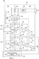
- FIG. 1 shows a schematic diagram of a first example of a pyro-fuse circuit 100 in accordance with example embodiments.
- the pyro-fuse circuit 100 includes a pyro-fuse control circuit 101, a conductor 122, a shunt resistor 124, and a pyro-fuse 126.
- the conductor 122 transmits electrical energy from an energy source, such as one or more batteries of a vehicle, to a load circuit, such as the electrical systems of a vehicle.
- the shunt resistor 124 is a current sensing resistor that is connected in series with conductor 122, and used, by the pyro-fuse control circuit 101, to measure the current flowing in the conductor 122 by measuring the voltage dropped across the shunt resistor 124.
- the pyro-fuse 126 is coupled to the conductor 122, and includes a piston driven cutting element 128 for severing the conductor 122 and an ignition control circuit 130 that activates a pyrotechnic charge to engage the piston driven cutting element 128 responsive to receipt of a triggering signal 154 provided by the pyro-fuse control circuit 101.
- the pyro-fuse control circuit 101 triggers activation of the pyro-fuse 126 responsive to excessive current flow in the conductor 122. For example, if the current flow in the conductor 122 is indicative of a short circuit of the conductor 122 to ground, then the pyro-fuse control circuit 101 triggers activation of the pyro-fuse 126 to sever the conductor 122 and isolate the power source from the load circuit.
- the pyro-fuse control circuit 101 includes a current sensing circuit 102 and a diagnostic circuit 104 that is coupled to the current sensing circuit 102.
- the current sensing circuit 102 measures the current flowing in the conductor 122 via the shunt resistor 124, and determines whether the current flowing in the conductor 122 exceeds a threshold.
- the diagnostic circuit 104 assesses the validity of the measurement performed by the current sensing circuit 102 by testing the paths of current flow to the current sensing circuit 102. Accordingly, the diagnostic circuit 104 determines whether an indication of current exceeding the threshold current generated by the current sensing circuit 102 is caused by current flowing in the conductor (122), or by a fault in the current sensing circuit 102.
- the current sensing circuit 102 includes an isolation amplifier 106 and a comparator 108.
- the circuitry of the pyro-fuse control circuit 101 operates across two power domains (i.e., the power domain 134 and the power domain 136), which may be referenced to different ground potentials.
- the isolation amplifier 106 measures voltage across the shunt resistor 124, and communicates the voltage across the shunt resistor 124 from the power domain 134 to the power domain 136.
- the isolation amplifier 106 includes an input section 162 (i.e., input circuits) that is disposed in the power domain 134 and an output section 164 (i.e., output circuits) that is disposed in the power domain 136.
- the isolation amplifier 106 is an AMC1301 reinforced isolated amplifier produced by Texas Instruments Incorporated, or other suitable isolation amplifier.
- the isolation amplifier 106 includes an input terminal 158 that is coupled to the shunt resistor 124 and an input terminal 160 that is coupled to the shunt resistor 124.
- An output signal 142 generated by the isolation amplifier 106 is provided to the comparator 108.
- the comparator 108 is coupled to the isolation amplifier 106 in the power domain 136, and compares the output signal 142 received from the isolation amplifier 106 to a threshold voltage 146.
- the threshold voltage 146 is representative of a threshold current that corresponds to excessive current flowing in the conductor 122. If the voltage of the output signal 142 exceeds the threshold voltage 146, then the comparator 108 generates an output signal 150 that indicates excessive current is flowing in the conductor 122.
- the pyro-fuse 126 may be triggered by on an indication of excessive current flowing in the conductor 122. However, if such an indication is erroneous, then triggering the pyro-fuse 126, which will disable a vehicle, is undesirable. The measurement of current flowing in the conductor 122 will be in error if an electrical connection between the isolation amplifier 106 and the conductor 122 is faulty. The diagnostic circuit 104 verifies the electrical connections between the conductor 122 and the isolation amplifier 106 to enable triggering of the pyro-fuse 126 when the current sensing circuit 102 generates an indication of excessive current flow in the conductor 122.
- the diagnostic circuit 104 includes an isolator 116, a switch 114, an isolation amplifier 110, and a comparator 112.
- the isolator 116 is coupled to the comparator 108, and includes input circuitry 172 that is disposed in the power domain 136 and output circuitry 170 that is disposed in the power domain 134.
- the isolator 116 communicates the output signal 150 generated by the comparator 108 from the power domain 136 to the power domain 134.
- the isolator 116 is implemented using an ISO7710 by Texas Instruments Incorporated, or other suitable isolator circuit.
- the isolator 116 is coupled to the switch 114 (i.e., to a control input of the switch 114).
- the switch 114 is implemented using an N-channel metal oxide semiconductor field effect transistor (MOSFET) in some implementations of the pyro-fuse control circuit 101.
- MOSFET metal oxide semiconductor field effect transistor
- the output signal 150 is propagated through the isolator 116 and closes the switch 114 to allow current to flow through the switch 114 to the input terminal 158 of the isolation amplifier 106, through the shunt resistor 124 to the input terminal 160 of the isolation amplifier 106, and through the resistor 132 to the ground in the power domain 134.
- the current flowing through the switch 114 is set by the resistor 176.
- the isolation amplifier 110 is coupled to the input terminal 160 of the isolation amplifier 106.
- the isolation amplifier 110 measures the voltage dropped across the resistor 132 as a measure of the current flowing in the input terminal 158, the shunt resistor 124, and the input terminal 160 by way of the switch 114.
- the isolation amplifier 110 communicates the voltage across the resistor 132 from the power domain 134 to the power domain 136.
- the isolation amplifier 110 includes an input section 166 (i.e., input circuits) that is disposed in the power domain 134 and an output section 168 (i.e., output circuits) that is disposed in the power domain 136.
- the isolation amplifier 110 is an AMC1311 reinforced isolated amplifier produced by Texas Instruments Incorporated, or other suitable isolation amplifier.
- An output signal 144 generated by the isolation amplifier 110 is provided to the comparator 112.
- the comparator 112 is coupled to the isolation amplifier 110 in the power domain 136, and the compares the output signal 144 received from the isolation amplifier 110 to a threshold voltage 148.
- the threshold voltage 148 is representative of current flow in the input terminal 160 of the isolation amplifier 106 that indicates intact electrical connections between the isolation amplifier 106 and the conductor 122. If the voltage of the output signal 144 exceeds the threshold voltage 148, then the comparator 112 generates an output signal 152 that indicates electrical connection of the isolation amplifier 106 to the conductor 122.
- the pyro-fuse control circuit 101 includes control circuity 174 that triggers the pyro-fuse 126 based on the output signal 150 generated by the comparator 108 and the output signal 152 generated by the comparator 112.
- the control circuity 174 includes a logic gate (i.e., an AND gate) 118 that generates a triggering signal 154 to trigger activation of the pyro-fuse 126 if the output signal 150 indicates that excessive current is flowing in the conductor 122 and the output signal 152 indicates that the isolation amplifier 106 is electrically connected to the conductor 122.
- the logic gate 118 is coupled to the pyro-fuse 126.
- pyro-fuse control circuit 101 provide the output signal 150 and the output signal 152 to circuits external to the pyro-fuse control circuit 101 for use in evaluating the status of the pyro-fuse circuit 100.
- Some implementations of the pyro-fuse control circuit 101 include a logic gate (i.e., an OR gate) 120 that asserts an output signal 156 if either of the output signal 150 or the output signal 152 is a logic one.
- the output signal 156 is a fault indicator signifying that excessive current has been detected or a fault in the pyro-fuse circuit 100 has been detected.
- the output signal 156 is active and the output signal 150 and the output signal 152 are active, then excessive current flow in the conductor 122 has been detected. If the output signal 156 is active, the output signal 150 is active, and the output signal 152 is inactive, then there is a fault in the electrical connection of the isolation amplifier 106 to the conductor 122 that should be corrected.
- the pyro-fuse control circuit 101 also includes a power supply 138 that generates power supply voltages for use by the control circuity 174 of the isolator 116, the input section 162 of the isolation amplifier 106, and the input section 166 of the isolation amplifier 110. Power signals are transmitted from the power domain 136 to the power domain 134 via a transformer 140.
- the pyro-circuit 100 provides a dedicated hardware pyro-fuse control circuit implementation that avoids software related issues, such as execution latency that delays triggering of the pyro-fuse 126, and software execution errors.
- FIG. 2 shows a schematic diagram of a second example of a pyro-fuse circuit 200 in accordance with example embodiments.
- the pyro-fuse circuit 200 includes a pyro-fuse control circuit 201, a conductor 122, a shunt resistor 124, a pyro-fuse 126, and processor 202.
- the conductor 122 transmits electrical energy from an energy source, such as one or more batteries of a vehicle, to a load circuit, such as the electrical systems of a vehicle.
- the shunt resistor 124 is a resistor used, by the pyro-fuse control circuit 201, to measure the current flowing in the conductor 122 by measuring the voltage dropped across the shunt resistor 124.
- the pyro-fuse 126 includes a piston driven cutting element 128 for severing the conductor 122 and an ignition control circuit 130 that activates a pyrotechnic charge to engage the 128 responsive to receipt of a triggering signal 154 provided by the pyro-fuse control circuit 201.
- the pyro-fuse control circuit 201 triggers activation of the pyro-fuse 126 responsive to excessive current flow in the conductor 122. For example, if the current flow in the conductor 122 is indicative of a short circuit of the conductor 122 to ground, then the pyro-fuse control circuit 201 triggers activation of the pyro-fuse 126 to isolate the power source from the load circuit.
- the pyro-fuse control circuit 201 includes a current sensing circuit 102 and a diagnostic circuit 104.
- the current sensing circuit 102 measures the current flowing in the conductor 122 via the shunt resistor 124.
- the diagnostic circuit 104 assesses the validity of the measurement performed by the current sensing circuit 102 by testing the paths of current flow to the current sensing circuit 102.
- the current sensing circuit 102 includes an isolation amplifier 106 and a comparator 108.
- the circuitry of the pyro-fuse control circuit 201 operates across two power domains (i.e., the power domain 134 and the power domain 134) that are, for example, referenced to different ground potentials.
- the isolation amplifier 106 communicates the voltage across the shunt resistor 124 from the power domain 134 to the power domain 236.
- the isolation amplifier 106 includes an input section 162 that is disposed in the power domain 134 and an output section 164 that is disposed in the power domain 236.
- the isolation amplifier 106 is an AMC1301 reinforced isolated amplifier produced by Texas Instruments Incorporated, or other suitable isolation amplifier.
- the isolation amplifier 106 includes an input terminal 158 that is coupled to the shunt resistor 124 and an input terminal 160 that is coupled to the shunt resistor 124.
- An output signal 142 generated by the isolation amplifier 106 is provided to the comparator 108.
- the comparator 108 is coupled to the isolation amplifier 106, and compares the output signal 142 received from the isolation amplifier 106 to a threshold voltage 146.
- the threshold voltage 146 is representative of a threshold current that corresponds to excessive current flowing in the conductor 122. If the voltage of the output signal 142 exceeds the threshold voltage 146, then the comparator 108 generates an output signal 150 that indicates excessive current is flowing in the conductor 122.
- the output signal 150 is provided to the processor 202.
- the processor 202 may be a microcontroller, a general-purpose microprocessor, or other device that executes instructions retrieved from a computer-readable medium to provide logical, arithmetic, and/or data transfer functionality.
- the processor 202 may be included in the pyro-fuse control circuit 201, or provided external to the pyro-fuse control circuit 201.
- the processor 202 is coupled to the pyro-fuse 126, and may trigger the pyro-fuse 126 based on an indication of excessive current flowing in the conductor 122. However, if such an indication is erroneous, then triggering the pyro-fuse 126, which will disable a vehicle, is undesirable. The measurement of current flowing in the conductor 122 will be in error if an electrical connection between the isolation amplifier 106 and the conductor 122 is faulty. The diagnostic circuit 104 verifies the electrical connections between the conductor 122 and the isolation amplifier 106 to enable triggering of the pyro-fuse 126 when the current sensing circuit 102 generates an indication of excessive current flow in the conductor 122.
- the diagnostic circuit 104 includes an isolator 116, a switch 114, an isolation amplifier 110, and a comparator 112.
- the isolator 116 is coupled to the processor 202, and includes input circuitry 172 that is disposed in the power domain 236 and output circuitry 170 that is disposed in the power domain 134.
- the processor 202 receives the output signal 150, the processor 202 activates the signal 204 to initiate diagnostic testing of the electrical connections between the isolation amplifier 106 and the conductor 122.
- the isolator 116 communicates the signal 204 generated by the processor 202 from the power domain 236 to the power domain 134.
- the isolator 116 is implemented using an ISO7710 by Texas Instruments Incorporated, or other suitable isolator circuit.
- the isolator 116 is coupled to the switch 114 in the power domain 134.
- the switch 114 is implemented using an N-channel MOSFET in some implementations of the pyro-fuse control circuit 201.
- the signal 204 propagates through the isolator 116 and closes the switch 114 to allow current to flow through the switch 114 to the input terminal 158 of the isolation amplifier 106, through the shunt resistor 124 to the input terminal 160 of the isolation amplifier 106, and through the resistor 132 to the ground in the power domain 134.
- the current flowing through the switch 114 is set by the resistor 176.
- the isolation amplifier 110 is coupled to the input terminal 160 of the isolation amplifier 106.
- the isolation amplifier 110 measures the voltage dropped across the resistor 132 as a measure of the current flowing in the input terminal 158, the shunt resistor 124, and the input terminal 160 by way of the switch 114.
- the isolation amplifier 110 communicates the voltage across the resistor 132 from the power domain 134 to the power domain 236.
- the isolation amplifier 110 includes an input section 166 that is disposed in the power domain 134 and an output section 168 that is disposed in the power domain 236.
- the isolation amplifier 110 is an AMC1311 reinforced isolated amplifier produced by Texas Instruments Incorporated, or other suitable isolation amplifier.
- An output signal 144 generated by the isolation amplifier 110 is provided to the comparator 112.
- the comparator 112 is coupled to the isolation amplifier 110, and compares the output signal 144 received from the isolation amplifier 110 to a threshold voltage 148.
- the threshold voltage 148 is representative of a current flow in the input terminal 160 of the isolation amplifier 106 that indicates intact electrical connections between the isolation amplifier 106 and the conductor 122. If the voltage of the output signal 144 exceeds the threshold voltage 148, then the comparator 112 generates an output signal 152 that indicates electrical connection of the isolation amplifier 106 to the conductor 122.
- the comparator 112 is coupled to the processor 202, and the output signal 152 is provided to the processor 202.
- the functionality of the control circuity 174 of the pyro-fuse control circuit 101 is provided by the processor 202.
- the processor 202 triggers the pyro-fuse 126 based on the output signal 150 generated by the comparator 108 and the output signal 152 generated by the comparator 112.
- the processor 202 is coupled to the pyro-fuse 126, and generates a signal 206 to trigger activation of the pyro-fuse 126 if the output signal 150 indicates that excessive current is flowing in the conductor 122 and the output signal 152 indicates that the isolation amplifier 106 is electrically connected to the conductor 122.
- the processor 202 monitors the output signal 150 and the output signal 152 to evaluate the status of the pyro-fuse circuit 200. For example, if the output signal 150 and the output signal 152 are active, then excessive current flow in the conductor 122 has been detected. If the output signal 150 is active, and the output signal 152 is inactive, then there is a fault in the electrical connection of the isolation amplifier 106 to the conductor 122 that should be corrected.
- the pyro-fuse control circuit 201 also includes a power supply 138 that generates power supply voltages for use by the output circuity 170 of the isolator 116, the input section 162 of the isolation amplifier 106, and the input section 166 of the isolation amplifier 110. Power signals are transmitted from the power domain 236 to the power domain 134 via a transformer 140.
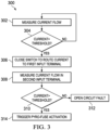
- FIG. 3 shows a flow diagram for a method 300 for controlling a pyro-fuse 126 in accordance with example embodiments. Though depicted sequentially as a matter of convenience, at least some of the actions shown can be performed in a different order and/or performed in parallel. Also, some implementations may perform only some of the actions shown.
- the comparator 108 is comparing the output signal 142 of the isolation amplifier 106 to a threshold voltage 146 that is representative of threshold current indicative of excessive current flow in the conductor 122. If, in block 304, the current flowing in the conductor 122 exceeds the threshold current, as shown by the output signal 142 exceeding the threshold voltage 146, then, the diagnostic circuit 104 is activated to test the electrical connection of the isolation amplifier 106 to the conductor 122.
- the switch 114 is closed to switch a current onto the input terminal 158 of the isolation amplifier 106. Closing of the switch 114 is controlled by the processor 202 or the comparator 108, via the isolator 116, in various implementations. If the input terminal 158 and the input terminal 160 of the isolation amplifier 106 are electrically connected to the conductor 122, then the current enabled by closing the switch 114 flows through the shunt resistor 124 to the input terminal 160, and through the resistor 132.
- the diagnostic circuit 104 measures the current flowing in the input terminal 160 via the voltage drop across the resistor 132.
- the comparator 112 is comparing the output signal 144 of the isolation amplifier 110 to a threshold voltage 148 that is representative of threshold current indicative of an electrical connection of the input terminal 158 and the input terminal 160 to the conductor 122. If, in block 310, the current flowing in the input terminal 160 exceeds the threshold current, as shown by the output signal 144 exceeding the threshold voltage 148, then, in block 314, activation of the pyro-fuse 126 is triggered. Triggering of the pyro-fuse 126 is controlled by the processor 202 or the logic gate 118 in various implementations.
- the detection of excess current flowing in the conductor 122 of block 304 may be due an open circuit fault (i.e., an open circuit in the electrical connection between the isolation amplifier 106 and the conductor 122) and the triggering of the pyro-fuse 126 is inhibited by the logic gate 118 or the processor 202.
- a fault indication may be generated responsive to the comparison of block 304 and/or the comparison block 310 indicating that a threshold has been exceeded.
Landscapes
- Engineering & Computer Science (AREA)
- Physics & Mathematics (AREA)
- Power Engineering (AREA)
- General Physics & Mathematics (AREA)
- Mechanical Engineering (AREA)
- Sustainable Development (AREA)
- Sustainable Energy (AREA)
- Transportation (AREA)
- Life Sciences & Earth Sciences (AREA)
- Nonlinear Science (AREA)
- Microelectronics & Electronic Packaging (AREA)
- Computer Hardware Design (AREA)
- Chemical & Material Sciences (AREA)
- Combustion & Propulsion (AREA)
- Artificial Intelligence (AREA)
- Evolutionary Computation (AREA)
- Emergency Protection Circuit Devices (AREA)
- Protection Of Static Devices (AREA)
Applications Claiming Priority (3)
| Application Number | Priority Date | Filing Date | Title |
|---|---|---|---|
| US201762576668P | 2017-10-25 | 2017-10-25 | |
| US16/018,759 US10833499B2 (en) | 2017-10-25 | 2018-06-26 | Pyro-fuse circuit |
| PCT/US2018/057564 WO2019084304A1 (en) | 2017-10-25 | 2018-10-25 | Pyro-fuse circuit |
Publications (3)
| Publication Number | Publication Date |
|---|---|
| EP3701609A1 EP3701609A1 (en) | 2020-09-02 |
| EP3701609A4 EP3701609A4 (en) | 2020-12-23 |
| EP3701609B1 true EP3701609B1 (en) | 2024-11-13 |
Family
ID=66170200
Family Applications (1)
| Application Number | Title | Priority Date | Filing Date |
|---|---|---|---|
| EP18870032.2A Active EP3701609B1 (en) | 2017-10-25 | 2018-10-25 | Pyro-fuse circuit |
Country Status (5)
| Country | Link |
|---|---|
| US (2) | US10833499B2 (https=) |
| EP (1) | EP3701609B1 (https=) |
| JP (1) | JP7227677B2 (https=) |
| CN (1) | CN111279571B (https=) |
| WO (1) | WO2019084304A1 (https=) |
Families Citing this family (24)
| Publication number | Priority date | Publication date | Assignee | Title |
|---|---|---|---|---|
| DE102017111413A1 (de) * | 2017-05-24 | 2018-11-29 | Dr. Ing. H.C. F. Porsche Aktiengesellschaft | Selbstauslösende Sprengsicherung |
| DE102019101236A1 (de) * | 2019-01-17 | 2020-07-23 | Liebherr-Components Biberach Gmbh | Ansteuervorrichtung zum Auslösen zumindest einer Pyrosicherung sowie Energiespeicher mit einer solchen Pyrosicherung |
| US11605945B2 (en) * | 2020-03-18 | 2023-03-14 | Samsung Sdi Co., Ltd. | Pyro igniter circuit and testing method |
| HUE059983T2 (hu) * | 2020-03-18 | 2023-01-28 | Samsung Sdi Co Ltd | Pirotechnikai gyújtó áramkör, és vizsgálati eljárás |
| JP7558486B2 (ja) * | 2020-07-29 | 2024-10-01 | 株式会社オートネットワーク技術研究所 | 直流回路開閉装置 |
| US11495982B2 (en) | 2020-08-31 | 2022-11-08 | The Boeing Company | System and method for allocating propulsion load power drawn from high-energy and high-power batteries |
| KR102504270B1 (ko) * | 2020-09-22 | 2023-02-24 | 삼성에스디아이 주식회사 | 배터리 보호 장치 및 이를 포함하는 배터리 시스템 |
| US11967842B2 (en) * | 2020-10-09 | 2024-04-23 | The Boeing Company | Smart battery disconnect and protection architecture for airborne high-power modular multi-string battery pack |
| WO2022115134A1 (en) * | 2020-11-30 | 2022-06-02 | Nikola Corporation | High voltage electrical system for battery electric vehicle |
| US11124076B1 (en) | 2020-11-30 | 2021-09-21 | Nikola Corporation | Electric vehicle battery frame assembly |
| US11820241B2 (en) | 2020-11-30 | 2023-11-21 | Nikola Corporation | Battery pack assembly |
| US12291112B2 (en) | 2020-11-30 | 2025-05-06 | Nikola Corporation | High voltage battery conditioning for battery electric vehicle |
| CN114624626B (zh) * | 2020-12-10 | 2025-10-10 | 意法半导体股份有限公司 | 过电流检测电路、对应的系统和方法 |
| EP4053874B1 (en) | 2021-03-01 | 2025-07-23 | Melexis Technologies SA | A contactor, an integrated circuit, a method of interrupting a current flow |
| CN112959889A (zh) * | 2021-03-28 | 2021-06-15 | 大运汽车股份有限公司 | 电动汽车突发状况快速断电装置 |
| JP7692180B2 (ja) * | 2021-06-14 | 2025-06-13 | パナソニックIpマネジメント株式会社 | 遮断装置 |
| US11878594B2 (en) | 2021-06-16 | 2024-01-23 | The Boeing Company | Protection system for aircraft electric propulsion motor and motor controller |
| JP7289875B2 (ja) * | 2021-06-24 | 2023-06-12 | 本田技研工業株式会社 | 燃料電池システム |
| EP4123858B1 (en) * | 2021-07-23 | 2023-07-12 | Munich Electrification GmbH | Battery management system and method for monitoring overcurrent in a battery management system |
| US20250158387A1 (en) * | 2022-02-28 | 2025-05-15 | Autonetworks Technologies, Ltd. | In-vehicle interrupting current supply device |
| CN118891797A (zh) * | 2022-04-08 | 2024-11-01 | 株式会社自动网络技术研究所 | 车载用切断电流供给装置 |
| JPWO2024236912A1 (https=) * | 2023-05-16 | 2024-11-21 | ||
| US20250007469A1 (en) * | 2023-06-30 | 2025-01-02 | Texas Instruments Incorporated | Compensation for redundant current limit architecture for safety devices |
| CN120280855A (zh) * | 2024-01-05 | 2025-07-08 | 霍尼韦尔国际公司 | 双输出电流传感器、提供短路保护的系统以及关联方法 |
Family Cites Families (17)
| Publication number | Priority date | Publication date | Assignee | Title |
|---|---|---|---|---|
| US4160282A (en) * | 1977-10-03 | 1979-07-03 | Consolidation Coal Company | Overcurrent protection apparatus |
| JPS59114736U (ja) * | 1983-01-19 | 1984-08-02 | 株式会社明電舎 | 無停電々源装置の保護装置 |
| US5099218A (en) * | 1990-12-07 | 1992-03-24 | Avx Corporation | Binary fuse device |
| RU2090896C1 (ru) | 1993-07-27 | 1997-09-20 | Юрчаков Валерий Павлович | Устройство для автоматического контроля системы электроснабжения транспортного средства |
| JPH09158717A (ja) * | 1995-12-08 | 1997-06-17 | Toyota Motor Corp | 電気加熱式触媒の電力供給制御装置 |
| US5629680A (en) | 1995-12-11 | 1997-05-13 | Makhija; Surender K. | Vehicle current drain tester with memory saver |
| JPH10229631A (ja) * | 1997-02-17 | 1998-08-25 | Hitachi Ltd | デジタルリレー装置のアナログ監視回路 |
| JP2004328886A (ja) | 2003-04-24 | 2004-11-18 | Hitachi Ltd | 自動監視回路 |
| FR2862816B1 (fr) | 2003-11-25 | 2006-04-28 | Electricfil Automotive | Dispositif intelligent de securite pour un equipement electrique embarque dans un vehicule |
| JP2009025055A (ja) | 2007-07-18 | 2009-02-05 | Kawamura Electric Inc | 変流器の出力変換回路 |
| JP5180783B2 (ja) * | 2008-11-12 | 2013-04-10 | 三菱重工業株式会社 | 超電導コイルクエンチの検出装置及び検出方法 |
| US8554500B2 (en) * | 2010-06-11 | 2013-10-08 | Deere & Company | System and method for ground isolation detection in a vehicle |
| TWM422090U (en) * | 2011-08-29 | 2012-02-01 | Richtek Technology Corp | Linear regulator and control circuit thereof |
| US9673611B2 (en) | 2012-02-21 | 2017-06-06 | Hamilton Sundstrand Corporation | Self-test of over-current fault detection |
| DE102014207302A1 (de) * | 2014-04-16 | 2015-10-22 | Robert Bosch Gmbh | Verfahren und Vorrichtung zum Abschalten zumindest einer Zündendstufe für eine Zündpille eines pyrotechnischen Schutzmittels für ein Fahrzeug |
| KR101631633B1 (ko) * | 2014-07-15 | 2016-06-17 | 엘에스산전 주식회사 | 고속 사고전류 검출 회로 |
| US9685901B2 (en) * | 2015-06-12 | 2017-06-20 | Semiconductor Components Industries, Llc | Motor controller with flexible protection modes |
-
2018
- 2018-06-26 US US16/018,759 patent/US10833499B2/en active Active
- 2018-10-25 JP JP2020523401A patent/JP7227677B2/ja active Active
- 2018-10-25 EP EP18870032.2A patent/EP3701609B1/en active Active
- 2018-10-25 WO PCT/US2018/057564 patent/WO2019084304A1/en not_active Ceased
- 2018-10-25 CN CN201880069556.2A patent/CN111279571B/zh active Active
-
2020
- 2020-09-30 US US17/039,237 patent/US11368012B2/en active Active
Also Published As
| Publication number | Publication date |
|---|---|
| US20210013708A1 (en) | 2021-01-14 |
| US11368012B2 (en) | 2022-06-21 |
| JP2021501551A (ja) | 2021-01-14 |
| CN111279571A (zh) | 2020-06-12 |
| EP3701609A1 (en) | 2020-09-02 |
| EP3701609A4 (en) | 2020-12-23 |
| US10833499B2 (en) | 2020-11-10 |
| WO2019084304A1 (en) | 2019-05-02 |
| JP7227677B2 (ja) | 2023-02-22 |
| US20190123542A1 (en) | 2019-04-25 |
| CN111279571B (zh) | 2022-04-19 |
Similar Documents
| Publication | Publication Date | Title |
|---|---|---|
| EP3701609B1 (en) | Pyro-fuse circuit | |
| CN109425816B (zh) | 测试mos功率开关 | |
| US9411016B2 (en) | Testing of a transient voltage protection device | |
| CN103250061B (zh) | 具有自检功能的不产生泄漏电流的绝缘电阻测量电路 | |
| US9194904B2 (en) | Systems and methods for detecting leakage paths in a battery sensing circuit | |
| US9341665B2 (en) | Method and apparatus for high voltage isolation monitor for a vehicle | |
| US9745947B2 (en) | Ignition control circuit with short circuit protection | |
| US11851013B2 (en) | Method for operating an electrically drivable motor vehicle and a device therefor | |
| US20200256924A1 (en) | Device and Method for Monitoring a Reliability of a Cell Impedance Measurement of a Battery Cell | |
| US10352990B2 (en) | Failure diagnosis circuit and failure diagnosis method | |
| US11290101B2 (en) | Solid state power switch device | |
| KR102291762B1 (ko) | 릴레이 진단 회로 | |
| US11418041B2 (en) | Battery system | |
| US9985427B2 (en) | Electronic circuit | |
| EP1763137B1 (en) | A driver circuit | |
| CN220234180U (zh) | 电子保险丝电路、电路系统及车辆 | |
| US10948530B2 (en) | Apparatus and method for asymmetrical isolation monitor failure detection | |
| US12003089B2 (en) | Short to ground protection and automatic recovery | |
| EP2857851B1 (en) | A device for diagnosing the condition of a fuse or a contact in a contactor and electromechanical assembly comprising such a diagnosing device | |
| CN113671232A (zh) | 一种剩余电流检测装置 | |
| EP4484975B1 (en) | Monitoring circuit and corresponding method | |
| RU2445300C1 (ru) | Устройство для включения пироклапана с электрическим запалом | |
| CN107356814B (zh) | 一种绝缘电阻检测系统 |
Legal Events
| Date | Code | Title | Description |
|---|---|---|---|
| STAA | Information on the status of an ep patent application or granted ep patent |
Free format text: STATUS: THE INTERNATIONAL PUBLICATION HAS BEEN MADE |
|
| PUAI | Public reference made under article 153(3) epc to a published international application that has entered the european phase |
Free format text: ORIGINAL CODE: 0009012 |
|
| STAA | Information on the status of an ep patent application or granted ep patent |
Free format text: STATUS: REQUEST FOR EXAMINATION WAS MADE |
|
| 17P | Request for examination filed |
Effective date: 20200525 |
|
| AK | Designated contracting states |
Kind code of ref document: A1 Designated state(s): AL AT BE BG CH CY CZ DE DK EE ES FI FR GB GR HR HU IE IS IT LI LT LU LV MC MK MT NL NO PL PT RO RS SE SI SK SM TR |
|
| AX | Request for extension of the european patent |
Extension state: BA ME |
|
| A4 | Supplementary search report drawn up and despatched |
Effective date: 20201123 |
|
| RIC1 | Information provided on ipc code assigned before grant |
Ipc: H01H 37/76 20060101ALI20201117BHEP Ipc: B60L 3/04 20060101ALI20201117BHEP Ipc: H03K 5/24 20060101ALI20201117BHEP Ipc: H03K 19/20 20060101ALI20201117BHEP Ipc: G01R 31/74 20200101ALI20201117BHEP Ipc: B60L 3/00 20190101ALI20201117BHEP Ipc: H02H 3/087 20060101ALI20201117BHEP Ipc: G01R 31/00 20060101ALI20201117BHEP Ipc: H02H 3/08 20060101AFI20201117BHEP Ipc: H01H 39/00 20060101ALI20201117BHEP |
|
| DAV | Request for validation of the european patent (deleted) | ||
| DAX | Request for extension of the european patent (deleted) | ||
| STAA | Information on the status of an ep patent application or granted ep patent |
Free format text: STATUS: EXAMINATION IS IN PROGRESS |
|
| 17Q | First examination report despatched |
Effective date: 20221014 |
|
| GRAP | Despatch of communication of intention to grant a patent |
Free format text: ORIGINAL CODE: EPIDOSNIGR1 |
|
| STAA | Information on the status of an ep patent application or granted ep patent |
Free format text: STATUS: GRANT OF PATENT IS INTENDED |
|
| INTG | Intention to grant announced |
Effective date: 20240625 |
|
| P01 | Opt-out of the competence of the unified patent court (upc) registered |
Free format text: CASE NUMBER: APP_40123/2024 Effective date: 20240705 |
|
| GRAS | Grant fee paid |
Free format text: ORIGINAL CODE: EPIDOSNIGR3 |
|
| GRAA | (expected) grant |
Free format text: ORIGINAL CODE: 0009210 |
|
| STAA | Information on the status of an ep patent application or granted ep patent |
Free format text: STATUS: THE PATENT HAS BEEN GRANTED |
|
| AK | Designated contracting states |
Kind code of ref document: B1 Designated state(s): AL AT BE BG CH CY CZ DE DK EE ES FI FR GB GR HR HU IE IS IT LI LT LU LV MC MK MT NL NO PL PT RO RS SE SI SK SM TR |
|
| REG | Reference to a national code |
Ref country code: GB Ref legal event code: FG4D |
|
| REG | Reference to a national code |
Ref country code: CH Ref legal event code: EP |
|
| REG | Reference to a national code |
Ref country code: DE Ref legal event code: R096 Ref document number: 602018076602 Country of ref document: DE |
|
| REG | Reference to a national code |
Ref country code: IE Ref legal event code: FG4D |
|
| REG | Reference to a national code |
Ref country code: LT Ref legal event code: MG9D |
|
| REG | Reference to a national code |
Ref country code: NL Ref legal event code: MP Effective date: 20241113 |
|
| PG25 | Lapsed in a contracting state [announced via postgrant information from national office to epo] |
Ref country code: IS Free format text: LAPSE BECAUSE OF FAILURE TO SUBMIT A TRANSLATION OF THE DESCRIPTION OR TO PAY THE FEE WITHIN THE PRESCRIBED TIME-LIMIT Effective date: 20250313 Ref country code: HR Free format text: LAPSE BECAUSE OF FAILURE TO SUBMIT A TRANSLATION OF THE DESCRIPTION OR TO PAY THE FEE WITHIN THE PRESCRIBED TIME-LIMIT Effective date: 20241113 Ref country code: PT Free format text: LAPSE BECAUSE OF FAILURE TO SUBMIT A TRANSLATION OF THE DESCRIPTION OR TO PAY THE FEE WITHIN THE PRESCRIBED TIME-LIMIT Effective date: 20250313 |
|
| PG25 | Lapsed in a contracting state [announced via postgrant information from national office to epo] |
Ref country code: FI Free format text: LAPSE BECAUSE OF FAILURE TO SUBMIT A TRANSLATION OF THE DESCRIPTION OR TO PAY THE FEE WITHIN THE PRESCRIBED TIME-LIMIT Effective date: 20241113 Ref country code: NL Free format text: LAPSE BECAUSE OF FAILURE TO SUBMIT A TRANSLATION OF THE DESCRIPTION OR TO PAY THE FEE WITHIN THE PRESCRIBED TIME-LIMIT Effective date: 20241113 |
|
| REG | Reference to a national code |
Ref country code: AT Ref legal event code: MK05 Ref document number: 1742417 Country of ref document: AT Kind code of ref document: T Effective date: 20241113 |
|
| PG25 | Lapsed in a contracting state [announced via postgrant information from national office to epo] |
Ref country code: BG Free format text: LAPSE BECAUSE OF FAILURE TO SUBMIT A TRANSLATION OF THE DESCRIPTION OR TO PAY THE FEE WITHIN THE PRESCRIBED TIME-LIMIT Effective date: 20241113 |
|
| PG25 | Lapsed in a contracting state [announced via postgrant information from national office to epo] |
Ref country code: ES Free format text: LAPSE BECAUSE OF FAILURE TO SUBMIT A TRANSLATION OF THE DESCRIPTION OR TO PAY THE FEE WITHIN THE PRESCRIBED TIME-LIMIT Effective date: 20241113 |
|
| PG25 | Lapsed in a contracting state [announced via postgrant information from national office to epo] |
Ref country code: NO Free format text: LAPSE BECAUSE OF FAILURE TO SUBMIT A TRANSLATION OF THE DESCRIPTION OR TO PAY THE FEE WITHIN THE PRESCRIBED TIME-LIMIT Effective date: 20250213 |
|
| PG25 | Lapsed in a contracting state [announced via postgrant information from national office to epo] |
Ref country code: AT Free format text: LAPSE BECAUSE OF FAILURE TO SUBMIT A TRANSLATION OF THE DESCRIPTION OR TO PAY THE FEE WITHIN THE PRESCRIBED TIME-LIMIT Effective date: 20241113 Ref country code: LV Free format text: LAPSE BECAUSE OF FAILURE TO SUBMIT A TRANSLATION OF THE DESCRIPTION OR TO PAY THE FEE WITHIN THE PRESCRIBED TIME-LIMIT Effective date: 20241113 Ref country code: GR Free format text: LAPSE BECAUSE OF FAILURE TO SUBMIT A TRANSLATION OF THE DESCRIPTION OR TO PAY THE FEE WITHIN THE PRESCRIBED TIME-LIMIT Effective date: 20250214 |
|
| PG25 | Lapsed in a contracting state [announced via postgrant information from national office to epo] |
Ref country code: PL Free format text: LAPSE BECAUSE OF FAILURE TO SUBMIT A TRANSLATION OF THE DESCRIPTION OR TO PAY THE FEE WITHIN THE PRESCRIBED TIME-LIMIT Effective date: 20241113 |
|
| PG25 | Lapsed in a contracting state [announced via postgrant information from national office to epo] |
Ref country code: RS Free format text: LAPSE BECAUSE OF FAILURE TO SUBMIT A TRANSLATION OF THE DESCRIPTION OR TO PAY THE FEE WITHIN THE PRESCRIBED TIME-LIMIT Effective date: 20250213 |
|
| PG25 | Lapsed in a contracting state [announced via postgrant information from national office to epo] |
Ref country code: SM Free format text: LAPSE BECAUSE OF FAILURE TO SUBMIT A TRANSLATION OF THE DESCRIPTION OR TO PAY THE FEE WITHIN THE PRESCRIBED TIME-LIMIT Effective date: 20241113 |
|
| PG25 | Lapsed in a contracting state [announced via postgrant information from national office to epo] |
Ref country code: DK Free format text: LAPSE BECAUSE OF FAILURE TO SUBMIT A TRANSLATION OF THE DESCRIPTION OR TO PAY THE FEE WITHIN THE PRESCRIBED TIME-LIMIT Effective date: 20241113 |
|
| PG25 | Lapsed in a contracting state [announced via postgrant information from national office to epo] |
Ref country code: EE Free format text: LAPSE BECAUSE OF FAILURE TO SUBMIT A TRANSLATION OF THE DESCRIPTION OR TO PAY THE FEE WITHIN THE PRESCRIBED TIME-LIMIT Effective date: 20241113 |
|
| PG25 | Lapsed in a contracting state [announced via postgrant information from national office to epo] |
Ref country code: RO Free format text: LAPSE BECAUSE OF FAILURE TO SUBMIT A TRANSLATION OF THE DESCRIPTION OR TO PAY THE FEE WITHIN THE PRESCRIBED TIME-LIMIT Effective date: 20241113 |
|
| PG25 | Lapsed in a contracting state [announced via postgrant information from national office to epo] |
Ref country code: SK Free format text: LAPSE BECAUSE OF FAILURE TO SUBMIT A TRANSLATION OF THE DESCRIPTION OR TO PAY THE FEE WITHIN THE PRESCRIBED TIME-LIMIT Effective date: 20241113 |
|
| PG25 | Lapsed in a contracting state [announced via postgrant information from national office to epo] |
Ref country code: CZ Free format text: LAPSE BECAUSE OF FAILURE TO SUBMIT A TRANSLATION OF THE DESCRIPTION OR TO PAY THE FEE WITHIN THE PRESCRIBED TIME-LIMIT Effective date: 20241113 |
|
| PG25 | Lapsed in a contracting state [announced via postgrant information from national office to epo] |
Ref country code: IT Free format text: LAPSE BECAUSE OF FAILURE TO SUBMIT A TRANSLATION OF THE DESCRIPTION OR TO PAY THE FEE WITHIN THE PRESCRIBED TIME-LIMIT Effective date: 20241113 |
|
| REG | Reference to a national code |
Ref country code: DE Ref legal event code: R097 Ref document number: 602018076602 Country of ref document: DE |
|
| PG25 | Lapsed in a contracting state [announced via postgrant information from national office to epo] |
Ref country code: SE Free format text: LAPSE BECAUSE OF FAILURE TO SUBMIT A TRANSLATION OF THE DESCRIPTION OR TO PAY THE FEE WITHIN THE PRESCRIBED TIME-LIMIT Effective date: 20241113 |
|
| PLBE | No opposition filed within time limit |
Free format text: ORIGINAL CODE: 0009261 |
|
| STAA | Information on the status of an ep patent application or granted ep patent |
Free format text: STATUS: NO OPPOSITION FILED WITHIN TIME LIMIT |
|
| PGFP | Annual fee paid to national office [announced via postgrant information from national office to epo] |
Ref country code: GB Payment date: 20250923 Year of fee payment: 8 |
|
| PGFP | Annual fee paid to national office [announced via postgrant information from national office to epo] |
Ref country code: FR Payment date: 20250925 Year of fee payment: 8 |
|
| 26N | No opposition filed |
Effective date: 20250814 |
|
| PGFP | Annual fee paid to national office [announced via postgrant information from national office to epo] |
Ref country code: DE Payment date: 20250923 Year of fee payment: 8 |