EP3701608B1 - Protective circuit for a field-effect transistor - Google Patents
Protective circuit for a field-effect transistor Download PDFInfo
- Publication number
- EP3701608B1 EP3701608B1 EP17794693.6A EP17794693A EP3701608B1 EP 3701608 B1 EP3701608 B1 EP 3701608B1 EP 17794693 A EP17794693 A EP 17794693A EP 3701608 B1 EP3701608 B1 EP 3701608B1
- Authority
- EP
- European Patent Office
- Prior art keywords
- field
- effect transistor
- electrical
- control device
- current
- Prior art date
- Legal status (The legal status is an assumption and is not a legal conclusion. Google has not performed a legal analysis and makes no representation as to the accuracy of the status listed.)
- Active
Links
- 230000005669 field effect Effects 0.000 title claims description 93
- 230000001681 protective effect Effects 0.000 title claims description 25
- 238000000034 method Methods 0.000 claims description 9
- 238000011156 evaluation Methods 0.000 description 5
- 238000006243 chemical reaction Methods 0.000 description 2
- 238000012544 monitoring process Methods 0.000 description 2
- 230000005540 biological transmission Effects 0.000 description 1
- 238000009529 body temperature measurement Methods 0.000 description 1
Images
Classifications
-
- H—ELECTRICITY
- H02—GENERATION; CONVERSION OR DISTRIBUTION OF ELECTRIC POWER
- H02H—EMERGENCY PROTECTIVE CIRCUIT ARRANGEMENTS
- H02H3/00—Emergency protective circuit arrangements for automatic disconnection directly responsive to an undesired change from normal electric working condition with or without subsequent reconnection ; integrated protection
- H02H3/08—Emergency protective circuit arrangements for automatic disconnection directly responsive to an undesired change from normal electric working condition with or without subsequent reconnection ; integrated protection responsive to excess current
- H02H3/085—Emergency protective circuit arrangements for automatic disconnection directly responsive to an undesired change from normal electric working condition with or without subsequent reconnection ; integrated protection responsive to excess current making use of a thermal sensor, e.g. thermistor, heated by the excess current
-
- B—PERFORMING OPERATIONS; TRANSPORTING
- B60—VEHICLES IN GENERAL
- B60R—VEHICLES, VEHICLE FITTINGS, OR VEHICLE PARTS, NOT OTHERWISE PROVIDED FOR
- B60R16/00—Electric or fluid circuits specially adapted for vehicles and not otherwise provided for; Arrangement of elements of electric or fluid circuits specially adapted for vehicles and not otherwise provided for
- B60R16/02—Electric or fluid circuits specially adapted for vehicles and not otherwise provided for; Arrangement of elements of electric or fluid circuits specially adapted for vehicles and not otherwise provided for electric constitutive elements
-
- G—PHYSICS
- G01—MEASURING; TESTING
- G01R—MEASURING ELECTRIC VARIABLES; MEASURING MAGNETIC VARIABLES
- G01R31/00—Arrangements for testing electric properties; Arrangements for locating electric faults; Arrangements for electrical testing characterised by what is being tested not provided for elsewhere
- G01R31/005—Testing of electric installations on transport means
- G01R31/006—Testing of electric installations on transport means on road vehicles, e.g. automobiles or trucks
-
- H—ELECTRICITY
- H02—GENERATION; CONVERSION OR DISTRIBUTION OF ELECTRIC POWER
- H02H—EMERGENCY PROTECTIVE CIRCUIT ARRANGEMENTS
- H02H1/00—Details of emergency protective circuit arrangements
- H02H1/0007—Details of emergency protective circuit arrangements concerning the detecting means
-
- H—ELECTRICITY
- H03—ELECTRONIC CIRCUITRY
- H03K—PULSE TECHNIQUE
- H03K17/00—Electronic switching or gating, i.e. not by contact-making and –breaking
- H03K17/08—Modifications for protecting switching circuit against overcurrent or overvoltage
- H03K17/081—Modifications for protecting switching circuit against overcurrent or overvoltage without feedback from the output circuit to the control circuit
- H03K17/0812—Modifications for protecting switching circuit against overcurrent or overvoltage without feedback from the output circuit to the control circuit by measures taken in the control circuit
- H03K17/08122—Modifications for protecting switching circuit against overcurrent or overvoltage without feedback from the output circuit to the control circuit by measures taken in the control circuit in field-effect transistor switches
-
- H—ELECTRICITY
- H03—ELECTRONIC CIRCUITRY
- H03K—PULSE TECHNIQUE
- H03K17/00—Electronic switching or gating, i.e. not by contact-making and –breaking
- H03K17/08—Modifications for protecting switching circuit against overcurrent or overvoltage
- H03K17/082—Modifications for protecting switching circuit against overcurrent or overvoltage by feedback from the output to the control circuit
- H03K17/0822—Modifications for protecting switching circuit against overcurrent or overvoltage by feedback from the output to the control circuit in field-effect transistor switches
-
- G—PHYSICS
- G01—MEASURING; TESTING
- G01R—MEASURING ELECTRIC VARIABLES; MEASURING MAGNETIC VARIABLES
- G01R31/00—Arrangements for testing electric properties; Arrangements for locating electric faults; Arrangements for electrical testing characterised by what is being tested not provided for elsewhere
- G01R31/327—Testing of circuit interrupters, switches or circuit-breakers
- G01R31/3277—Testing of circuit interrupters, switches or circuit-breakers of low voltage devices, e.g. domestic or industrial devices, such as motor protections, relays, rotation switches
-
- G—PHYSICS
- G01—MEASURING; TESTING
- G01R—MEASURING ELECTRIC VARIABLES; MEASURING MAGNETIC VARIABLES
- G01R31/00—Arrangements for testing electric properties; Arrangements for locating electric faults; Arrangements for electrical testing characterised by what is being tested not provided for elsewhere
- G01R31/40—Testing power supplies
-
- H—ELECTRICITY
- H02—GENERATION; CONVERSION OR DISTRIBUTION OF ELECTRIC POWER
- H02H—EMERGENCY PROTECTIVE CIRCUIT ARRANGEMENTS
- H02H7/00—Emergency protective circuit arrangements specially adapted for specific types of electric machines or apparatus or for sectionalised protection of cable or line systems, and effecting automatic switching in the event of an undesired change from normal working conditions
- H02H7/08—Emergency protective circuit arrangements specially adapted for specific types of electric machines or apparatus or for sectionalised protection of cable or line systems, and effecting automatic switching in the event of an undesired change from normal working conditions for dynamo-electric motors
-
- H—ELECTRICITY
- H02—GENERATION; CONVERSION OR DISTRIBUTION OF ELECTRIC POWER
- H02H—EMERGENCY PROTECTIVE CIRCUIT ARRANGEMENTS
- H02H7/00—Emergency protective circuit arrangements specially adapted for specific types of electric machines or apparatus or for sectionalised protection of cable or line systems, and effecting automatic switching in the event of an undesired change from normal working conditions
- H02H7/22—Emergency protective circuit arrangements specially adapted for specific types of electric machines or apparatus or for sectionalised protection of cable or line systems, and effecting automatic switching in the event of an undesired change from normal working conditions for distribution gear, e.g. bus-bar systems; for switching devices
- H02H7/222—Emergency protective circuit arrangements specially adapted for specific types of electric machines or apparatus or for sectionalised protection of cable or line systems, and effecting automatic switching in the event of an undesired change from normal working conditions for distribution gear, e.g. bus-bar systems; for switching devices for switches
-
- H—ELECTRICITY
- H03—ELECTRONIC CIRCUITRY
- H03K—PULSE TECHNIQUE
- H03K17/00—Electronic switching or gating, i.e. not by contact-making and –breaking
- H03K17/08—Modifications for protecting switching circuit against overcurrent or overvoltage
- H03K2017/0806—Modifications for protecting switching circuit against overcurrent or overvoltage against excessive temperature
Definitions
- the present invention relates to a protection circuit for a first field effect transistor, the protection circuit being used in particular in a motor vehicle.
- a field effect transistor includes a source connection, a drain connection and a gate connection. An electrically conductive connection between the source connection and drain connection can be switched on and off via the gate connection.
- FETs field effect transistors
- US 7,759, 891 B2 It is known that temperature monitoring of a FET is provided in such a circuit. The temperature monitoring is intended to protect a motor controlled via the FET from damage. It is assumed that exceeding a temperature limit z. B. occurs in the event of an electrical short circuit. Therefore, the temperature of the FET is compared with an ambient temperature and, as soon as the difference temperature determined in this way exceeds the specified limit, current transmission via the FET is switched off. A more differentiated evaluation of the cause of reaching the limit value is not possible.
- the US 5,959,464 is directed to a circuit with a transistor for providing a current from a voltage source to a consumer.
- the current conducted via the transistor is determined from a known voltage and a resistance determined from a determined temperature of the transistor.
- the object of the invention is therefore to at least partially solve the problems associated with the prior art and, in particular, to provide a protective circuit through which an accurate evaluation of the electrical currents conducted via a field-effect transistor is possible.
- the aim is to provide the most cost-effective protective circuit possible.
- a protective circuit which includes at least a first field-effect transistor, a control device and a first temperature sensor, contributes to this.
- the first field effect transistor has a first source connection, a first drain connection and a first gate connection.
- the control device can be used to determine an electrical first voltage [Volt] between the first source connection and the first drain connection. With the first temperature sensor there is a changing first temperature [degrees Celsius] of the first field effect transistor detectable. Using the first temperature, the control device can be used to determine a first (electrical) resistance [Ohm] of the first field-effect transistor and (therefore) a first electrical current (current in [ampere]) conducted via the first field-effect transistor.
- the (current) first temperature of the first field effect transistor using sensors and/or calculations.
- this is in particular not compared with an ambient temperature.
- only the first temperature is determined and thus a conclusion is drawn about a first resistance of the first field effect transistor that changes as a function of the first temperature. Knowing the first voltage dropping across the first field-effect transistor and the first resistance, a first electrical current conducted via the first field-effect transistor can then be determined (in particular by calculation).
- a characteristic of the first field-effect transistor i.e. a change in the first electrical resistance as a function of a first temperature of the first field-effect transistor, is known and stored in the control unit.
- a linear relationship (at least in the working area) between the first temperature and the first resistance can be predefined here.
- This linear relationship is preferably present at least in a region of the first resistance in which the amount of the first resistance changes between 50% and 200% of an average value of the first resistance.
- the mean value of the first resistance is at a predetermined reference temperature of the first temperature, e.g. B. at 20 degrees Celsius.
- the first field effect transistor is connected to a voltage source via the first drain connection, between the voltage source and the first Field effect transistor a second field effect transistor is arranged.
- the second field effect transistor has a second source connection, a second drain connection and a second gate connection.
- An electrical second voltage between the second source connection and the second drain connection can be determined by means of the control device.
- a changing second temperature of the second field effect transistor can be detected (sensorily) by the second temperature sensor. Based on the second temperature, a second electrical resistance of the second field-effect transistor and (therefore) a second electrical current conducted via the second field-effect transistor can be determined (as described above for the first field-effect transistor).
- the voltage source in particular provides a voltage of at most 100 volts, in particular 12 volts, 24 volts or 48 volts.
- the first source connection can be connected to at least one electrical machine and to an electrical ground via the electrical machine.
- a third field-effect transistor is arranged between the electrical machine and the mass, an electrical measuring resistor being arranged between the third field-effect transistor and the mass for determining a third electrical current conducted via the third field-effect transistor.
- the measuring resistor (also referred to as a shunt) is in particular a low-resistance electrical resistor that is used (possibly essentially only) to measure the electrical current strength.
- the current flowing through a shunt causes a voltage drop proportional to its strength, which is measured.
- the measuring resistor is electrically connected to the control unit so that a current conducted via the third field effect transistor can be monitored with the control unit.
- the electric machine can have a nominal power [watt] of less than 10 kilowatts, in particular less than 5 kilowatts, preferably less than 1 kilowatt.
- At least the first electrical current (and/or the second current) can be measured via the changing first temperature (or second temperature) with an accuracy of less than 2.0 amperes, in particular less than 1.5 amperes, preferably less than 1, 0 amperes, can be determined.
- At least the first temperature sensor (and/or the second temperature sensor) can be connected to the control unit via an analog-digital converter.
- Analog signals from a temperature sensor can be converted into digital signals using the analog-digital converter. The conversion can take place with a required resolution so that an electrical current can be determined with a required or required accuracy.
- a motor vehicle with an electric machine and with a protective circuit described above is proposed, wherein the first source connection of the first field effect transistor is connected to at least the electric machine and to an electrical ground via the electric machine.
- the first source connection is connected to at least one electrical machine and to an electrical ground via the electrical machine, with a third field effect transistor being arranged between the electrical machine and the electrical ground.
- a measuring resistor for determining a third electrical current conducted via the third field effect transistor can be arranged between the third field effect transistor and the electrical ground.
- the third current is determined, with an evaluation of the first current and the third current (and/or the second current) taking place in the control device in a process ii).
- a conclusion can be drawn about the status of the protective circuit.
- short circuits can be identified and evaluated.
- a decision can be made as to whether operation of the protective circuit can be continued, whether a warning message should be sent or whether the operation of the protective circuit should be interrupted at least temporarily or continued to a limited extent.
- Limit values are stored in the control unit so that certain measures can be initiated when certain limit values are reached.
- first, second, third, etc. primarily serve (only) to distinguish between several similar objects, sizes or processes, i.e. in particular no dependency and/or order of these objects, sizes or processes in relation to each other. If a dependency and/or sequence is required, this is explicitly stated here or it will be obvious to the person skilled in the art when studying the specifically described embodiment.
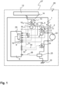
- Fig. 1 shows a motor vehicle 27 with an electrical circuit 28, which includes a protective circuit 1.
- the electrical circuit 28 includes a voltage source 12, an electrical machine 22 and a mass 23.
- a control device 6 regulates and monitors the operation of the electrical machine 22 via the circuit 28.
- the protective circuit 1 for the first field-effect transistor 2 includes the first field-effect transistor 2, a control device 6 and a first temperature sensor 8.
- the first field effect transistor 2 has a first drain connection 3, a first source connection 4 and a first gate connection 5.
- An electrical first voltage 7 between the first drain connection 3 and the first source connection 4 can be determined with the control device 6.
- a changing first temperature 9 of the first field effect transistor 2 can be detected with the first temperature sensor 8.
- a first resistance 10 of the first field-effect transistor 2 and thus a first electrical current 11 conducted via the first field-effect transistor 2 can be determined based on the first temperature 9.
- first temperature 9 is determined and thus a conclusion is drawn about a first resistance 10 of the first field effect transistor 2 that changes as a function of the first temperature 9. Knowing the first voltage 7 dropping across the first field effect transistor 2 and the first resistor 10, a first electrical current 11 conducted via the first field effect transistor 2 can be determined.
- the first field effect transistor 2 is connected to the voltage source 12 via the first drain connection 3, a second field effect transistor 13 being arranged between the voltage source 12 and the first field effect transistor 2.
- the second field effect transistor 13 has a second drain connection 14, a second source connection 15 and a second gate connection 16.
- An electrical second voltage 17 between the second drain connection 14 and the second source connection 15 can be determined by the control device 6.
- a changing second temperature 19 of the second field effect transistor 13 can be detected by a second temperature sensor 18. Based on the second Temperature 19 is a second resistor 20 of the second field effect transistor 13 and thus a second electrical current 21 conducted via the second field effect transistor 13 can be determined.
- a third field-effect transistor 24 is arranged between the electrical machine 22 and the mass 23, with a measuring resistor 25 being routed between the third field-effect transistor 24 and the mass 23 to determine a field-effect transistor 24 conducted via the third field-effect transistor 24 electrical third current 26 is arranged.
- the measuring resistor 25 is connected to the control device 6, so that a third current 26 conducted via the third field-effect transistor 24 can be monitored with the control device 6.
- the first temperature sensor 8 and the second temperature sensor 18 are connected to the control unit 6 via an analog-digital converter 29.
- Analog signals from the temperature sensors 8, 18 can be converted into digital signals via the analog-digital converter 29.
- the conversion can take place with a required resolution, so that an electrical current 11, 21 can be determined with a required or required accuracy.
- the electrical voltages 7, 17 can also be detected via the analog-digital converter 29 and, in particular, converted into digital signals.
- a conclusion can be drawn about the state of the protective circuit 1 or the circuit 28.
- short circuits can be identified and evaluated. Based on the evaluation, a decision can be made as to whether operation of the protective circuit 1 or the circuit 28 can be continued, whether a warning message should be issued or whether the operation of the protective circuit 1/circuit 28 should be interrupted at least temporarily or continued to a limited extent.
- Limit values for ratios of currents 11, 21, 26 etc. are stored in the control device 6, so that certain measures can be initiated when certain limit values are reached.
- Limit values for currents 11, 21, 26 can be stored in the control unit.
- the control device 6 can transmit control signals 30, 31, 32 to the gate connections 5, 16 of the field effect transistors 2, 13, 24 and the field effect transistors 2, 13, 24 can be switched accordingly.
Description
Die vorliegende Erfindung betrifft eine Schutzschaltung für einen ersten Feld-Effekt-Transistor, wobei die Schutzschaltung insbesondere in einem Kraftfahrzeug eingesetzt wird. Ein Feld-Effekt-Transistor umfasst einen Source-Anschluss, einen Drain-Anschluss sowie einen Gate-Anschluss. Über den Gate-Anschluss kann eine elektrisch leitende Verbindung zwischen Source-Anschluss und Drain-Anschluss ein- und ausgeschaltet werden.The present invention relates to a protection circuit for a first field effect transistor, the protection circuit being used in particular in a motor vehicle. A field effect transistor includes a source connection, a drain connection and a gate connection. An electrically conductive connection between the source connection and drain connection can be switched on and off via the gate connection.
Einige Schaltungen mit Feld-Effekt-Transistoren (sogenannte FETs) zur Ansteuerung von Pumpen, Stellmotoren oder anderen Aggregaten sind bereits bekannt. Aus der
Aus der
Aus der
Die
Aufgabe der Erfindung ist es daher, die mit Bezug auf den Stand der Technik vorhandenen Probleme zumindest teilweise zu lösen und insbesondere eine Schutzschaltung bereitzustellen, durch die eine genaue Auswertung der über einen Feld-Effekt-Transistor geleiteten elektrischen Ströme möglich ist. Dabei soll eine möglichst kostengünstige Schutzschaltung bereitgestellt werden.The object of the invention is therefore to at least partially solve the problems associated with the prior art and, in particular, to provide a protective circuit through which an accurate evaluation of the electrical currents conducted via a field-effect transistor is possible. The aim is to provide the most cost-effective protective circuit possible.
Diese Aufgaben werden gelöst mit einer Schutzschaltung bzw. einem Verfahren gemäß den Merkmalen der Patentansprüche 1 und 6. Weitere vorteilhafte Ausgestaltungen der Schutzschaltung und der Erfindung sind in den weiteren Patentansprüchen angegeben. Darüber hinaus werden die in den Patentansprüchen angegebenen Merkmale in der Beschreibung näher präzisiert und erläutert, wobei weitere bevorzugte Ausgestaltungen der Erfindung dargestellt werden.These tasks are solved with a protective circuit or a method according to the features of
Hierzu trägt eine Schutzschaltung bei, die zumindest einen ersten Feld-Effekt-Transistor, ein Steuergerät sowie einen ersten Temperatursensor umfasst. Der erste Feld-Effekt-Transistor weist einen ersten Source-Anschluss, einen ersten Drain-Anschluss und einen ersten Gate-Anschluss auf. Mit dem Steuergerät ist eine elektrische erste Spannung [Volt] zwischen dem ersten Source-Anschluss und dem ersten Drain-Anschluss ermittelbar. Mit dem ersten Temperatursensor ist eine sich ändernde erste Temperatur [Grad Celsius] des ersten Feld-Effekt-Transistors erfassbar. Mit dem Steuergerät ist anhand der ersten Temperatur ein erster (elektrischer) Widerstand [Ohm] des ersten Feld-Effekt-Transistors und (damit) ein über den ersten Feld-Effekt-Transistor geleiteter elektrischer erster Strom (Stromstärke in [Ampere]) ermittelbar.A protective circuit, which includes at least a first field-effect transistor, a control device and a first temperature sensor, contributes to this. The first field effect transistor has a first source connection, a first drain connection and a first gate connection. The control device can be used to determine an electrical first voltage [Volt] between the first source connection and the first drain connection. With the first temperature sensor there is a changing first temperature [degrees Celsius] of the first field effect transistor detectable. Using the first temperature, the control device can be used to determine a first (electrical) resistance [Ohm] of the first field-effect transistor and (therefore) a first electrical current (current in [ampere]) conducted via the first field-effect transistor.
Es wird hier insbesondere vorgeschlagen, die (aktuelle) erste Temperatur des ersten Feld-Effekt-Transistors sensorisch und/oder rechnerisch zu ermitteln. Diese wird aber insbesondere nicht mit einer Umgebungstemperatur verglichen. Hier wird insbesondere ausschließlich die erste Temperatur ermittelt und damit auf einen sich in Abhängigkeit von der ersten Temperatur ändernden ersten Widerstand des ersten Feld-Effekt-Transistors geschlossen. In Kenntnis der über den ersten Feld-Effekt-Transistor abfallenden ersten Spannung und des ersten Widerstands ist dann ein über den ersten Feld-Effekt-Transistor geleiteter elektrischer erster Strom (insbesondere rechnerisch) ermittelbar.In particular, it is proposed here to determine the (current) first temperature of the first field effect transistor using sensors and/or calculations. However, this is in particular not compared with an ambient temperature. Here, in particular, only the first temperature is determined and thus a conclusion is drawn about a first resistance of the first field effect transistor that changes as a function of the first temperature. Knowing the first voltage dropping across the first field-effect transistor and the first resistance, a first electrical current conducted via the first field-effect transistor can then be determined (in particular by calculation).
Dafür ist eine Charakteristik des ersten Feld-Effekt-Transistors, also eine Veränderung des ersten elektrischen Widerstands in Abhängigkeit von einer ersten Temperatur des ersten Feld-Effekt-Transistors, bekannt und im Steuergerät hinterlegt.For this purpose, a characteristic of the first field-effect transistor, i.e. a change in the first electrical resistance as a function of a first temperature of the first field-effect transistor, is known and stored in the control unit.
Insbesondere kann hier ein (zumindest im Arbeitsbereich annährend) linearer Zusammenhang zwischen erster Temperatur und erstem Widerstand vordefiniert sein. Dieser lineare Zusammenhang liegt bevorzugt zumindest in einem Bereich des ersten Widerstands vor, in dem sich der Betrag des ersten Widerstands zwischen 50 % und 200 % eines Mittelwerts des ersten Widerstands verändert. Der Mittelwert des ersten Widerstands liegt bei einer vorgegebenen Referenztemperatur der ersten Temperatur vor, z. B. bei 20 Grad Celsius.In particular, a linear relationship (at least in the working area) between the first temperature and the first resistance can be predefined here. This linear relationship is preferably present at least in a region of the first resistance in which the amount of the first resistance changes between 50% and 200% of an average value of the first resistance. The mean value of the first resistance is at a predetermined reference temperature of the first temperature, e.g. B. at 20 degrees Celsius.
Der erste Feld-Effekt-Transistor ist über den ersten Drain-Anschluss mit einer Spannungsquelle verbunden, wobei zwischen der Spannungsquelle und dem ersten Feld-Effekt-Transistor ein zweiter Feld-Effekt-Transistor angeordnet ist. Der zweite Feld-Effekt-Transistor weist einen zweiten Source-Anschluss, einen zweiten Drain-Anschluss und einen zweiten Gate-Anschluss auf. Mittels des Steuergeräts ist eine elektrische zweite Spannung zwischen dem zweiten Source-Anschluss und dem zweiten Drain-Anschluss ermittelbar. Durch den zweiten Temperatursensor ist eine sich ändernde zweite Temperatur des zweiten Feld-Effekt-Transistors (sensorisch) erfassbar. Anhand der zweiten Temperatur ist ein zweiter elektrischer Widerstand des zweiten Feld-Effekt-Transistors und (damit) ein über den zweiten Feld-Effekt-Transistor geleiteter elektrischer zweiter Strom ermittelbar (wie vorstehend für den ersten Feld-Effekt-Transistor beschrieben).The first field effect transistor is connected to a voltage source via the first drain connection, between the voltage source and the first Field effect transistor a second field effect transistor is arranged. The second field effect transistor has a second source connection, a second drain connection and a second gate connection. An electrical second voltage between the second source connection and the second drain connection can be determined by means of the control device. A changing second temperature of the second field effect transistor can be detected (sensorily) by the second temperature sensor. Based on the second temperature, a second electrical resistance of the second field-effect transistor and (therefore) a second electrical current conducted via the second field-effect transistor can be determined (as described above for the first field-effect transistor).
Die Spannungsquelle stellt insbesondere eine Spannung von höchstens 100 Volt bereit, insbesondere 12 Volt, 24 Volt oder 48 Volt.The voltage source in particular provides a voltage of at most 100 volts, in particular 12 volts, 24 volts or 48 volts.
Der erste Source-Anschluss ist mit zumindest einer elektrischen Maschine und über die elektrische Maschine mit einer elektrischen Masse verbindbar.The first source connection can be connected to at least one electrical machine and to an electrical ground via the electrical machine.
Zwischen der elektrischen Maschine und der Masse ist ein dritter Feld-Effekt-Transistor angeordnet, wobei zwischen dem dritten Feld-Effekt-Transistor und der Masse ein elektrischer Messwiderstand zur Ermittlung eines über den dritten Feld-Effekt-Transistor geleiteten elektrischen dritten Stroms angeordnet ist.A third field-effect transistor is arranged between the electrical machine and the mass, an electrical measuring resistor being arranged between the third field-effect transistor and the mass for determining a third electrical current conducted via the third field-effect transistor.
Der Messwiderstand (auch als Shunt bezeichnet) ist insbesondere ein niederohmiger elektrischer Widerstand, der (ggf. im Wesentlichen nur) zur Messung der elektrischen Stromstärke verwendet wird. Der Strom, der durch einen Shunt fließt, verursacht einen zu seiner Stärke proportionalen Spannungsabfall, der gemessen wird.The measuring resistor (also referred to as a shunt) is in particular a low-resistance electrical resistor that is used (possibly essentially only) to measure the electrical current strength. The current flowing through a shunt causes a voltage drop proportional to its strength, which is measured.
Der Messwiderstand ist mit dem Steuergerät elektrisch leitend verbunden, so dass ein über den dritten Feld-Effekt-Transistor geleiteter Strom mit dem Steuergerät überwacht werden kann.The measuring resistor is electrically connected to the control unit so that a current conducted via the third field effect transistor can be monitored with the control unit.
Die Anordnung eines solchen Messwiderstands bzw. eines zusätzlichen Messwiderstands in der Schaltung bzw. Schutzschaltung (also im Bereich des ersten und zweiten Feld-Effekt-Transistors) ist kostspielig. Hier wird also vorgeschlagen, zumindest in Ergänzung zu dem einen Messwiderstand (und/oder als Ersatz für den Messwiderstand) zumindest einen Temperatursensor zur Erfassung einer Änderung des Widerstands eines Feld-Effekt-Transistors vorzusehen, so dass anhand der Änderung des Widerstands auf den durch den Feld-Effekt-Transistor geleiteten elektrischen Strom geschlossen werden kann.The arrangement of such a measuring resistor or an additional measuring resistor in the circuit or protective circuit (i.e. in the area of the first and second field-effect transistor) is expensive. It is therefore proposed here to provide at least one temperature sensor for detecting a change in the resistance of a field-effect transistor, at least in addition to the one measuring resistor (and/or as a replacement for the measuring resistor), so that based on the change in resistance on the through the Field effect transistor conducted electrical current can be closed.
Die elektrische Maschine kann eine Nennleistung [Watt] von weniger als 10 Kilowatt, insbesondere von weniger als 5 Kilowatt, bevorzugt von weniger als 1 Kilowatt, aufweisen.The electric machine can have a nominal power [watt] of less than 10 kilowatts, in particular less than 5 kilowatts, preferably less than 1 kilowatt.
Zumindest der erste elektrische Strom (und/oder der zweite Strom) kann über die sich ändernde erste Temperatur (bzw. zweite Temperatur) mit einer Genauigkeit von weniger als 2,0 Ampere, insbesondere weniger als 1,5 Ampere, bevorzugt weniger als 1,0 Ampere, bestimmbar sein.At least the first electrical current (and/or the second current) can be measured via the changing first temperature (or second temperature) with an accuracy of less than 2.0 amperes, in particular less than 1.5 amperes, preferably less than 1, 0 amperes, can be determined.
Zumindest der erste Temperatursensor (und/oder der zweite Temperatursensor) kann über einen Analog-Digital-Wandler mit dem Steuergerät verbunden sein. Über den Analog-Digital-Wandler können analoge Signale eines Temperatursensors in digitale Signale umgewandelt werden. Die Umwandlung kann mit einer geforderten Auflösung erfolgen, so dass ein elektrischer Strom mit einer geforderten oder benötigten Genauigkeit ermittelbar ist.At least the first temperature sensor (and/or the second temperature sensor) can be connected to the control unit via an analog-digital converter. Analog signals from a temperature sensor can be converted into digital signals using the analog-digital converter. The conversion can take place with a required resolution so that an electrical current can be determined with a required or required accuracy.
Es wird ein Kraftfahrzeug mit einer elektrischen Maschine und mit einer vorstehend beschriebenen Schutzschaltung vorgeschlagen, wobei der erste Source-Anschluss des ersten Feld-Effekt-Transistors mit zumindest der elektrischen Maschine und über die elektrische Maschine mit einer elektrischen Masse verbunden ist.A motor vehicle with an electric machine and with a protective circuit described above is proposed, wherein the first source connection of the first field effect transistor is connected to at least the electric machine and to an electrical ground via the electric machine.
Die Ausführungen zu der Schutzschaltung können einzeln und in Kombination miteinander zur Erläuterung für das Kraftfahrzeug herangezogen werden und umgekehrt.The statements on the protective circuit can be used individually and in combination with each other to explain the motor vehicle and vice versa.
Es wird zudem ein Verfahren zum Betrieb bzw. Schutz einer elektrischen Schaltung vorgeschlagen, wobei die elektrische Schaltung zumindest eine vorstehend beschriebene Schutzschaltung aufweist. Das Verfahren weist zumindest die folgenden Schritte auf:
- a) Ermitteln einer elektrischen ersten Spannung zwischen dem ersten Source-Anschluss und dem ersten Drain-Anschluss;
- b) Erfassen einer ersten Temperatur des ersten Feld-Effekt-Transistors;
- c) Berechnen eines über den ersten Feld-Effekt-Transistor geleiteten elektrischen ersten Stroms (mit dem Steuergerät).
- a) determining an electrical first voltage between the first source connection and the first drain connection;
- b) detecting a first temperature of the first field effect transistor;
- c) Calculating a first electrical current conducted via the first field effect transistor (with the control device).
Der erste Source-Anschluss ist mit zumindest einer elektrischen Maschine und über die elektrische Maschine mit einer elektrischen Masse verbunden, wobei zwischen der elektrischen Maschine und der elektrischen Masse ein dritter Feld-Effekt-Transistor angeordnet ist. Zwischen dem dritten Feld-Effekt-Transistor und der elektrischen Masse ist ein Messwiderstand zur Ermittlung eines über den dritten Feld-Effekt-Transistor geleiteten elektrischen dritten Stroms angeordnet sein. In einem Prozess i) wird der dritte Strom ermittelt, wobei in einem Prozess ii) in dem Steuergerät eine Auswertung des ersten Stroms und des dritten Stroms (und/oder des zweiten Stroms) erfolgt.The first source connection is connected to at least one electrical machine and to an electrical ground via the electrical machine, with a third field effect transistor being arranged between the electrical machine and the electrical ground. A measuring resistor for determining a third electrical current conducted via the third field effect transistor can be arranged between the third field effect transistor and the electrical ground. In a process i), the third current is determined, with an evaluation of the first current and the third current (and/or the second current) taking place in the control device in a process ii).
Durch die Auswertung der einzelnen elektrischen Ströme kann auf einen Zustand der Schutzschaltung geschlossen werden. Insbesondere sind so Kurzschlüsse erkennbar und bewertbar. Anhand der Auswertung kann eine Entscheidung getroffen werden, ob ein Betrieb der Schutzschaltung fortgesetzt werden kann, ob eine Warnmeldung abgesetzt werden soll oder ob der Betrieb der Schutzschaltung zumindest zeitweise unterbrochen oder eingeschränkt fortgeführt werden soll. In dem Steuergerät sind Grenzwerte hinterlegt, so dass bei Erreichen bestimmter Grenzwerte bestimmte Maßnahmen eingeleitet werden können.By evaluating the individual electrical currents, a conclusion can be drawn about the status of the protective circuit. In particular, short circuits can be identified and evaluated. Based on the evaluation, a decision can be made as to whether operation of the protective circuit can be continued, whether a warning message should be sent or whether the operation of the protective circuit should be interrupted at least temporarily or continued to a limited extent. Limit values are stored in the control unit so that certain measures can be initiated when certain limit values are reached.
Die Ausführungen zu dem Verfahren können einzeln und in Kombination miteinander zur Erläuterung für die Schutzschaltung und/oder das Kraftfahrzeug herangezogen werden und umgekehrt.The statements on the method can be used individually and in combination with one another to explain the protective circuit and/or the motor vehicle and vice versa.
Vorsorglich sei angemerkt, dass die hier verwendeten Zahlwörter ("erste", "zweite", "dritte",...) vorrangig (nur) zur Unterscheidung von mehreren gleichartigen Gegenständen, Größen oder Prozessen dienen, also insbesondere keine Abhängigkeit und/oder Reihenfolge dieser Gegenstände, Größen oder Prozesse zueinander zwingend vorgeben. Sollte eine Abhängigkeit und/oder Reihenfolge erforderlich sein, ist dies hier explizit angegeben oder es ergibt sich offensichtlich für den Fachmann beim Studium der konkret beschriebenen Ausgestaltung.As a precaution, it should be noted that the number words used here ("first", "second", "third",...) primarily serve (only) to distinguish between several similar objects, sizes or processes, i.e. in particular no dependency and/or order of these objects, sizes or processes in relation to each other. If a dependency and/or sequence is required, this is explicitly stated here or it will be obvious to the person skilled in the art when studying the specifically described embodiment.
Die Erfindung sowie das technische Umfeld werden nachfolgend anhand der schematischen Figur näher erläutert. Es ist darauf hinzuweisen, dass die Erfindung durch das gezeigte Ausführungsbeispiel nicht beschränkt werden soll, sondern durch den Gegenstand der unabhängigen Patentansprüche definiert ist.The invention and the technical environment are explained in more detail below using the schematic figure. It should be noted that the invention is not intended to be limited by the exemplary embodiment shown, but is defined by the subject matter of the independent patent claims.
Hier wird ausschließlich die erste Temperatur 9 ermittelt und damit auf einen sich in Abhängigkeit von der ersten Temperatur 9 ändernden ersten Widerstand 10 des ersten Feld-Effekt-Transistors 2 geschlossen. In Kenntnis der über den ersten Feld-Effekt-Transistor 2 abfallenden ersten Spannung 7 und des ersten Widerstands 10 ist ein über den ersten Feld-Effekt-Transistor 2 geleiteter elektrischer erster Strom 11 ermittelbar.Here only the first temperature 9 is determined and thus a conclusion is drawn about a
Der erste Feld-Effekt-Transistor 2 ist über den ersten Drain-Anschluss 3 mit der Spannungsquelle 12 verbunden, wobei zwischen der Spannungsquelle 12 und dem ersten Feld-Effekt-Transistor 2 ein zweiter Feld-Effekt-Transistor 13 angeordnet ist. Der zweite Feld-Effekt-Transistor 13 weist einen zweiten Drain-Anschluss 14, einen zweiten Source-Anschluss 15 und einen zweiten Gate-Anschluss 16 auf. Durch das Steuergerät 6 ist eine elektrische zweite Spannung 17 zwischen dem zweiten Drain-Anschluss 14 und dem zweiten Source-Anschluss 15 ermittelbar. Durch einen zweiten Temperatursensor 18 ist eine sich ändernde zweite Temperatur 19 des zweiten Feld-Effekt-Transistors 13 erfassbar. Anhand der zweiten Temperatur 19 ist ein zweiter Widerstand 20 des zweiten Feld-Effekt-Transistors 13 und damit ein über den zweiten Feld-Effekt-Transistor 13 geleiteter elektrischer zweiter Strom 21 ermittelbar.The first
Zwischen der elektrischen Maschine 22 und der Masse 23 ist ein dritter Feld-Effekt-Transistor 24 angeordnet, wobei zwischen dem dritten Feld-Effekt-Transistor 24 und der Masse 23 ein Messwiderstand 25 zur Ermittlung eines über den dritten Feld-Effekt-Transistor 24 geleiteten elektrischen dritten Stroms 26 angeordnet ist.A third field-
Der Messwiderstand 25 ist mit dem Steuergerät 6 verbunden, so dass ein über den dritten Feld-Effekt-Transistor 24 geleiteter dritter Strom 26 mit dem Steuergerät 6 überwacht werden kann.The measuring
Der erste Temperatursensor 8 und der zweite Temperatursensor 18 sind über einen Analog-Digital-Wandler 29 mit dem Steuergerät 6 verbunden. Über den Analog-Digital-Wandler 29 können analoge Signale der Temperatursensoren 8, 18 in digitale Signale umgewandelt werden. Die Umwandlung kann mit einer geforderten Auflösung erfolgen, so dass ein elektrischer Strom 11, 21 mit einer geforderten oder benötigten Genauigkeit ermittelbar ist. Über den Analog-Digital-Wandler 29 können auch die elektrischen Spannungen 7, 17 erfasst und insbesondere in digitale Signale umgewandelt werden.The
Durch die Auswertung der einzelnen elektrischen Ströme 11, 21, 26 kann auf einen Zustand der Schutzschaltung 1 bzw. der Schaltung 28 geschlossen werden. Insbesondere sind so Kurzschlüsse erkennbar und bewertbar. Anhand der Auswertung kann eine Entscheidung getroffen werden, ob ein Betrieb der Schutzschaltung 1 bzw. der Schaltung 28 fortgesetzt werden kann, ob eine Warnmeldung abgesetzt werden soll oder ob der Betrieb der Schutzschaltung 1/Schaltung 28 zumindest zeitweise unterbrochen oder eingeschränkt fortgeführt werden soll.By evaluating the individual
Im Steuergerät 6 sind Grenzwerte für Verhältnisse von Strömen 11, 21, 26 etc. hinterlegt, so dass bei Erreichen bestimmter Grenzwerte bestimmte Maßnahmen eingeleitet werden können. Es können Grenzwerte für Ströme 11, 21, 26 im Steuergerät hinterlegt werden.Limit values for ratios of
Durch das Steuergerät 6 können Steuersignale 30, 31, 32 an die Gate-Anschlüsse 5, 16 der Feld-Effekt-Transistoren 2, 13, 24 übermittelt und eine dementsprechende Schaltung der Feld-Effekt-Transistoren 2, 13, 24 vorgenommen werden.The
- 11
- SchutzschaltungProtection circuit
- 22
- erster Feld-Effekt-Transistorfirst field effect transistor
- 33
- erster Drain-Anschlussfirst drain connection
- 44
- erster Source-Anschlussfirst source connection
- 55
- erster Gate-Anschlussfirst gate connection
- 66
- SteuergerätControl unit
- 77
- erste Spannungfirst tension
- 88th
- erster Temperatursensorfirst temperature sensor
- 99
- erste Temperaturfirst temperature
- 1010
- erster Widerstandfirst resistance
- 1111
- erster Stromfirst stream
- 1212
- Spannungsquellevoltage source
- 1313
- zweiter Feld-Effekt-Transistorsecond field effect transistor
- 1414
- zweiter Drain-Anschlusssecond drain connection
- 1515
- zweiter Source-Anschlusssecond source connection
- 1616
- zweiter Gate-Anschlusssecond gate connection
- 1717
- zweite Spannungsecond tension
- 1818
- zweiter Temperatursensorsecond temperature sensor
- 1919
- zweite Temperatursecond temperature
- 2020
- zweiter Widerstandsecond resistance
- 2121
- zweiter Stromsecond stream
- 2222
- elektrische Maschineelectric machine
- 2323
- MasseDimensions
- 2424
- dritter Feld-Effekt-Transistorthird field effect transistor
- 2525
- Messwiderstandmeasuring resistance
- 2626
- dritter Stromthird stream
- 2727
- Kraftfahrzeugmotor vehicle
- 2828
- Schaltungcircuit
- 2929
- Analog-Digital-WandlerAnalog-to-digital converter
- 3030
- erstes Steuersignalfirst control signal
- 3131
- zweites Steuersignalsecond control signal
- 3232
- drittes Steuersignalthird control signal
Claims (6)
- Protective circuit (1) for a first field-effect transistor (2), at least comprising the first field-effect transistor (2), a control device (6), a first temperature sensor (8), a second field-effect transistor (13), a third field-effect transistor (24), a second temperature sensor (18), and a measuring resistor (25), wherein first field-effect transistor (2) has a first drain terminal (3), a first source terminal (4) and a first gate terminal (5), wherein by means of the control device (6) an electrical first voltage (7) between the first drain terminal (3) and the first source terminal (4) is determinable and a characteristic of the first field-effect transistor (2), that is to say a variation of the first electrical resistance (10) as a function of a first temperature (9) of the first field-effect transistor (2), is stored in the control device (6), wherein by means of the first temperature sensor (8) the changing first temperature (9) of the first field-effect transistor (2) is detectable; wherein the first resistance (10) of the first field-effect transistor (2) and an electrical first current (11) conducted via the first field-effect transistor (2) are determinable by the control device (6); wherein the first source terminal (4) is connected to a electrical machine (22) and to a ground (23) via the electrical machine (22); wherein the third field-effect transistor (24) is arranged between the electrical machine (22) and the ground (23), characterized in that the first field-effect transistor (2) is connectable to a voltage source (12) via the first drain terminal (3), wherein the second field-effect transistor (13) is arranged between the voltage source (12) and the first field-effect transistor (2) which has a second drain terminal (14), a second source terminal (15) and a second gate terminal (16); wherein an electrical second voltage (17) between the second drain terminal (14) and the second source terminal (15) is determinable by means of the control device (6); wherein a changing second temperature (19) of the second field-effect transistor (13) is furthermore detectable by means of the second temperature sensor (18); wherein a second resistance (20) of the second field-effect transistor (13) and an electrical second current (21) conducted via the second field-effect transistor (13) are determinable on the basis of the second temperature (19); wherein the measuring resistor (25) for determining an electrical third current (26) conducted via the third field-effect transistor (24) is arranged between the third field-effect transistor (24) and the ground (23); wherein the measuring resistor (25) is electrically connected with the control device (6), wherein the control device (6) is set up to monitor the third current (26); wherein limit values for ratios of determined currents (11, 21, 26) are stored in the control device (6), wherein the control device (6) is set up to communicate control signals (30, 31, 32) to the gate terminals (5, 16) of the field-effect transistors (2, 13, 24) once specific limit values are reached, so that corresponding switching of the field-effect transistors (2, 13, 24) can be performed.
- Protective circuit (1) as claimed in claim 1, wherein the electrical machine (22) has a rated power of less than 10 kilowatts.
- Protective circuit (1) as claimed in any of the preceding claims, wherein at least the first current (11) is ascertainable with an accuracy of less than 2.0 amperes by way of the changing first temperature (9).
- Protective circuit (1) as claimed in any of the preceding claims, wherein at least the first temperature sensor (8) is connected to the control device (6) via an analog-to-digital convertor (29).
- Motor vehicle (27) comprising the electrical machine (22), the ground (23), the voltage source (12), and the protective circuit (1) as claimed in any of the preceding claims; wherein the first drain terminal (4) of the first field-effect transistor (2) is connected to at least the electrical machine (22) and to the electrical ground (23) via the electrical machine (22).
- Method for operating an electrical circuit (28) comprising at least one protective circuit (1) as claimed in any of the preceding claims 1 to 4; at least comprising the following steps:a) determining an electrical first voltage (7) between the first drain terminal (3) and the first source terminal (4);b) detecting a first temperature (9) of the first field-effect transistor (2);c) calculating an electrical first current (11) conducted via the first field-effect transistor (2) based on the first temperature (9) and calculating an electrical first current (11) conducted via the first field-effect transistor (2);wherein the first source terminal (4) is connected to the electrical machine (22) and to a ground (23) via the electrical machine (22); wherein the third field-effect transistor (24) is arranged between the electrical machine (22) and the ground (23), characterized in that the measuring resistor (25) for determining an electrical third current (26) conducted via the third field-effect transistor (24) is arranged between the third field-effect transistor (24) and the ground (23); wherein in a step i) the third current (26) is determined and in a step ii) the first current (11) and the third current (26) are evaluated in the control device (6); wherein limit values for ratios of the determined currents (11, 21, 26) are stored in the control device (6) and by means of the control device (6), once specific limit values are reached, control signals (30, 31, 32) are communicated to the gate terminals (5, 16) of the field-effect transistors (2, 13, 24) and corresponding switching of the field-effect transistors (2, 13, 24) is performed.
Applications Claiming Priority (1)
| Application Number | Priority Date | Filing Date | Title |
|---|---|---|---|
| PCT/EP2017/076970 WO2019080989A1 (en) | 2017-10-23 | 2017-10-23 | Protective circuit for a field-effect transistor |
Publications (2)
| Publication Number | Publication Date |
|---|---|
| EP3701608A1 EP3701608A1 (en) | 2020-09-02 |
| EP3701608B1 true EP3701608B1 (en) | 2023-10-11 |
Family
ID=60268355
Family Applications (1)
| Application Number | Title | Priority Date | Filing Date |
|---|---|---|---|
| EP17794693.6A Active EP3701608B1 (en) | 2017-10-23 | 2017-10-23 | Protective circuit for a field-effect transistor |
Country Status (5)
| Country | Link |
|---|---|
| US (1) | US11456588B2 (en) |
| EP (1) | EP3701608B1 (en) |
| JP (1) | JP7185698B2 (en) |
| CN (1) | CN111226365A (en) |
| WO (1) | WO2019080989A1 (en) |
Family Cites Families (7)
| Publication number | Priority date | Publication date | Assignee | Title |
|---|---|---|---|---|
| US5719519A (en) * | 1995-11-20 | 1998-02-17 | Motorola, Inc. | Circuit and method for reconstructing a phase current |
| US5959464A (en) | 1996-09-03 | 1999-09-28 | Motorola Inc. | Loss-less load current sensing driver and method therefor |
| DE102006029332A1 (en) | 2006-06-23 | 2008-01-03 | Automotive Components Holdings, LLC, Dearborn | Direct current electric motor e.g. fan motor, control unit for motor vehicle, has monitoring circuit for monitoring controller for motor, and equalization assembly damping high frequency oscillation of voltage that falls at FET |
| JP4964536B2 (en) | 2006-08-31 | 2012-07-04 | 矢崎総業株式会社 | Motor abnormality detection device and method |
| JP5743739B2 (en) * | 2011-06-22 | 2015-07-01 | 株式会社東芝 | Power storage device |
| US8847575B2 (en) | 2011-10-14 | 2014-09-30 | Infineon Technologies Ag | Circuit arrangement |
| US9263877B1 (en) | 2014-12-30 | 2016-02-16 | Api Technologies Corp. | Temperature-compensated current monitoring |
-
2017
- 2017-10-23 WO PCT/EP2017/076970 patent/WO2019080989A1/en unknown
- 2017-10-23 JP JP2020542496A patent/JP7185698B2/en active Active
- 2017-10-23 EP EP17794693.6A patent/EP3701608B1/en active Active
- 2017-10-23 CN CN201780096209.4A patent/CN111226365A/en active Pending
- 2017-10-23 US US16/758,145 patent/US11456588B2/en active Active
Also Published As
| Publication number | Publication date |
|---|---|
| EP3701608A1 (en) | 2020-09-02 |
| JP7185698B2 (en) | 2022-12-07 |
| WO2019080989A1 (en) | 2019-05-02 |
| CN111226365A (en) | 2020-06-02 |
| US20200287371A1 (en) | 2020-09-10 |
| JP2021500829A (en) | 2021-01-07 |
| US11456588B2 (en) | 2022-09-27 |
Similar Documents
| Publication | Publication Date | Title |
|---|---|---|
| DE102012222749B4 (en) | Method and system for calibrating battery current measurement | |
| EP3197704B1 (en) | Circuit device and method for ascertaining a state of a locking conductor loop | |
| EP2205984B1 (en) | Circuit arrangement for monitoring an electrical insulation | |
| DE102014107561B4 (en) | Current measurement and overcurrent detection | |
| EP2618439B1 (en) | Protective circuit for a battery pack | |
| EP3417305B1 (en) | Battery sensor, method for calibrating a shunt resistor and use | |
| DE112008003096T5 (en) | Cable protection method and cable protection device | |
| DE102014202626A1 (en) | Battery management system for a battery with multiple battery cells and method | |
| EP3612846B1 (en) | Device and power supply for a control unit and method for monitoring a power supply | |
| WO2019043063A1 (en) | Monitoring device for monitoring an electrical energy source with respect to the source voltage thereof and the insulation resistances thereof, high-voltage system, and method for operating the monitoring device | |
| DE102013209142A1 (en) | Method for determining an insulation resistance of a power supply network of a vehicle comprising several subnetworks | |
| DE102014111416B4 (en) | Securing a line | |
| WO2009043657A1 (en) | Diagnostic method and device in integrated power bridge circuits | |
| EP2880410B1 (en) | Multiwire measuring device for detecting a defective, temperature-dependent resistance sensor | |
| EP3257120B1 (en) | Multistage coordinated overvoltage arrester circuit | |
| EP3669145B1 (en) | Control unit comprising a circuit, and method for short-circuit protection of ground lines and sensors | |
| EP3701608B1 (en) | Protective circuit for a field-effect transistor | |
| DE102005039573A1 (en) | Circuit arrangement for detecting and evaluating electrical and physical measured variables in an electrical switching device | |
| DE102017116009B3 (en) | METHOD AND DEVICE FOR DETECTING LIGHT BOWS | |
| WO2016139263A1 (en) | Method and device for determining a load current | |
| DE102013105439B4 (en) | FLOATING CONNECTION OF A DIODE FOR BARRIER TEMPERATURE MEASUREMENT | |
| DE10343179A1 (en) | Current measurement device, especially for monitoring the current of an automotive battery, has voltage measurement means assigned to at least one of a number of consumer fuses | |
| WO2011085958A1 (en) | Device for electric circuit monitoring | |
| DE102014224639A1 (en) | Method and monitoring device for detecting a fault current for a control device for controlling a multiphase actuator | |
| WO2015197230A1 (en) | Method and apparatus for sensing small currents |
Legal Events
| Date | Code | Title | Description |
|---|---|---|---|
| STAA | Information on the status of an ep patent application or granted ep patent |
Free format text: STATUS: UNKNOWN |
|
| STAA | Information on the status of an ep patent application or granted ep patent |
Free format text: STATUS: THE INTERNATIONAL PUBLICATION HAS BEEN MADE |
|
| PUAI | Public reference made under article 153(3) epc to a published international application that has entered the european phase |
Free format text: ORIGINAL CODE: 0009012 |
|
| STAA | Information on the status of an ep patent application or granted ep patent |
Free format text: STATUS: REQUEST FOR EXAMINATION WAS MADE |
|
| 17P | Request for examination filed |
Effective date: 20200518 |
|
| AK | Designated contracting states |
Kind code of ref document: A1 Designated state(s): AL AT BE BG CH CY CZ DE DK EE ES FI FR GB GR HR HU IE IS IT LI LT LU LV MC MK MT NL NO PL PT RO RS SE SI SK SM TR |
|
| AX | Request for extension of the european patent |
Extension state: BA ME |
|
| DAV | Request for validation of the european patent (deleted) | ||
| DAX | Request for extension of the european patent (deleted) | ||
| STAA | Information on the status of an ep patent application or granted ep patent |
Free format text: STATUS: EXAMINATION IS IN PROGRESS |
|
| 17Q | First examination report despatched |
Effective date: 20220310 |
|
| GRAP | Despatch of communication of intention to grant a patent |
Free format text: ORIGINAL CODE: EPIDOSNIGR1 |
|
| STAA | Information on the status of an ep patent application or granted ep patent |
Free format text: STATUS: GRANT OF PATENT IS INTENDED |
|
| RIC1 | Information provided on ipc code assigned before grant |
Ipc: H03K 17/08 20060101ALN20230428BHEP Ipc: H02H 7/22 20060101ALN20230428BHEP Ipc: G01R 31/40 20200101ALN20230428BHEP Ipc: H03K 17/082 20060101ALI20230428BHEP Ipc: G01R 31/327 20060101ALI20230428BHEP Ipc: H03K 17/0812 20060101ALI20230428BHEP Ipc: H02H 7/08 20060101ALI20230428BHEP Ipc: H02H 3/08 20060101AFI20230428BHEP |
|
| RIC1 | Information provided on ipc code assigned before grant |
Ipc: H03K 17/08 20060101ALN20230516BHEP Ipc: H02H 7/22 20060101ALN20230516BHEP Ipc: G01R 31/40 20200101ALN20230516BHEP Ipc: H03K 17/082 20060101ALI20230516BHEP Ipc: G01R 31/327 20060101ALI20230516BHEP Ipc: H03K 17/0812 20060101ALI20230516BHEP Ipc: H02H 7/08 20060101ALI20230516BHEP Ipc: H02H 3/08 20060101AFI20230516BHEP |
|
| INTG | Intention to grant announced |
Effective date: 20230602 |
|
| GRAS | Grant fee paid |
Free format text: ORIGINAL CODE: EPIDOSNIGR3 |
|
| GRAA | (expected) grant |
Free format text: ORIGINAL CODE: 0009210 |
|
| STAA | Information on the status of an ep patent application or granted ep patent |
Free format text: STATUS: THE PATENT HAS BEEN GRANTED |
|
| AK | Designated contracting states |
Kind code of ref document: B1 Designated state(s): AL AT BE BG CH CY CZ DE DK EE ES FI FR GB GR HR HU IE IS IT LI LT LU LV MC MK MT NL NO PL PT RO RS SE SI SK SM TR |
|
| REG | Reference to a national code |
Ref country code: GB Ref legal event code: FG4D Free format text: NOT ENGLISH |
|
| REG | Reference to a national code |
Ref country code: CH Ref legal event code: EP |
|
| REG | Reference to a national code |
Ref country code: DE Ref legal event code: R096 Ref document number: 502017015485 Country of ref document: DE |
|
| REG | Reference to a national code |
Ref country code: IE Ref legal event code: FG4D Free format text: LANGUAGE OF EP DOCUMENT: GERMAN |
|
| PGFP | Annual fee paid to national office [announced via postgrant information from national office to epo] |
Ref country code: DE Payment date: 20231201 Year of fee payment: 7 |
|
| REG | Reference to a national code |
Ref country code: LT Ref legal event code: MG9D |
|
| REG | Reference to a national code |
Ref country code: NL Ref legal event code: MP Effective date: 20231011 |
|
| PG25 | Lapsed in a contracting state [announced via postgrant information from national office to epo] |
Ref country code: NL Free format text: LAPSE BECAUSE OF FAILURE TO SUBMIT A TRANSLATION OF THE DESCRIPTION OR TO PAY THE FEE WITHIN THE PRESCRIBED TIME-LIMIT Effective date: 20231011 |
|
| PG25 | Lapsed in a contracting state [announced via postgrant information from national office to epo] |
Ref country code: GR Free format text: LAPSE BECAUSE OF FAILURE TO SUBMIT A TRANSLATION OF THE DESCRIPTION OR TO PAY THE FEE WITHIN THE PRESCRIBED TIME-LIMIT Effective date: 20240112 |
|
| PG25 | Lapsed in a contracting state [announced via postgrant information from national office to epo] |
Ref country code: IS Free format text: LAPSE BECAUSE OF FAILURE TO SUBMIT A TRANSLATION OF THE DESCRIPTION OR TO PAY THE FEE WITHIN THE PRESCRIBED TIME-LIMIT Effective date: 20240211 |