EP3701506B1 - Roller shutter for securing a physical space within a vehicle - Google Patents
Roller shutter for securing a physical space within a vehicle Download PDFInfo
- Publication number
- EP3701506B1 EP3701506B1 EP18786815.3A EP18786815A EP3701506B1 EP 3701506 B1 EP3701506 B1 EP 3701506B1 EP 18786815 A EP18786815 A EP 18786815A EP 3701506 B1 EP3701506 B1 EP 3701506B1
- Authority
- EP
- European Patent Office
- Prior art keywords
- roller shutter
- mesh
- vehicle
- user
- protective barrier
- Prior art date
- Legal status (The legal status is an assumption and is not a legal conclusion. Google has not performed a legal analysis and makes no representation as to the accuracy of the status listed.)
- Active
Links
Images


Classifications
-
- E—FIXED CONSTRUCTIONS
- E05—LOCKS; KEYS; WINDOW OR DOOR FITTINGS; SAFES
- E05F—DEVICES FOR MOVING WINGS INTO OPEN OR CLOSED POSITION; CHECKS FOR WINGS; WING FITTINGS NOT OTHERWISE PROVIDED FOR, CONCERNED WITH THE FUNCTIONING OF THE WING
- E05F15/00—Power-operated mechanisms for wings
- E05F15/70—Power-operated mechanisms for wings with automatic actuation
- E05F15/73—Power-operated mechanisms for wings with automatic actuation responsive to movement or presence of persons or objects
- E05F15/76—Power-operated mechanisms for wings with automatic actuation responsive to movement or presence of persons or objects responsive to devices carried by persons or objects, e.g. magnets or reflectors
-
- G—PHYSICS
- G08—SIGNALLING
- G08B—SIGNALLING SYSTEMS, e.g. PERSONAL CALLING SYSTEMS; ORDER TELEGRAPHS; ALARM SYSTEMS
- G08B13/00—Burglar, theft or intruder alarms
- G08B13/02—Mechanical actuation
- G08B13/12—Mechanical actuation by the breaking or disturbance of stretched cords or wires
- G08B13/126—Mechanical actuation by the breaking or disturbance of stretched cords or wires for a housing, e.g. a box, a safe, or a room
-
- B—PERFORMING OPERATIONS; TRANSPORTING
- B60—VEHICLES IN GENERAL
- B60R—VEHICLES, VEHICLE FITTINGS, OR VEHICLE PARTS, NOT OTHERWISE PROVIDED FOR
- B60R25/00—Fittings or systems for preventing or indicating unauthorised use or theft of vehicles
- B60R25/10—Fittings or systems for preventing or indicating unauthorised use or theft of vehicles actuating a signalling device
- B60R25/1004—Alarm systems characterised by the type of sensor, e.g. current sensing means
-
- E—FIXED CONSTRUCTIONS
- E05—LOCKS; KEYS; WINDOW OR DOOR FITTINGS; SAFES
- E05F—DEVICES FOR MOVING WINGS INTO OPEN OR CLOSED POSITION; CHECKS FOR WINGS; WING FITTINGS NOT OTHERWISE PROVIDED FOR, CONCERNED WITH THE FUNCTIONING OF THE WING
- E05F15/00—Power-operated mechanisms for wings
- E05F15/40—Safety devices, e.g. detection of obstructions or end positions
- E05F15/42—Detection using safety edges
- E05F15/44—Detection using safety edges responsive to changes in electrical conductivity
-
- G—PHYSICS
- G08—SIGNALLING
- G08B—SIGNALLING SYSTEMS, e.g. PERSONAL CALLING SYSTEMS; ORDER TELEGRAPHS; ALARM SYSTEMS
- G08B25/00—Alarm systems in which the location of the alarm condition is signalled to a central station, e.g. fire or police telegraphic systems
- G08B25/008—Alarm setting and unsetting, i.e. arming or disarming of the security system
-
- E—FIXED CONSTRUCTIONS
- E05—LOCKS; KEYS; WINDOW OR DOOR FITTINGS; SAFES
- E05Y—INDEXING SCHEME ASSOCIATED WITH SUBCLASSES E05D AND E05F, RELATING TO CONSTRUCTION ELEMENTS, ELECTRIC CONTROL, POWER SUPPLY, POWER SIGNAL OR TRANSMISSION, USER INTERFACES, MOUNTING OR COUPLING, DETAILS, ACCESSORIES, AUXILIARY OPERATIONS NOT OTHERWISE PROVIDED FOR, APPLICATION THEREOF
- E05Y2400/00—Electronic control; Electrical power; Power supply; Power or signal transmission; User interfaces
- E05Y2400/10—Electronic control
- E05Y2400/52—Safety arrangements associated with the wing motor
- E05Y2400/525—Car-jacking prevention
-
- E—FIXED CONSTRUCTIONS
- E05—LOCKS; KEYS; WINDOW OR DOOR FITTINGS; SAFES
- E05Y—INDEXING SCHEME ASSOCIATED WITH SUBCLASSES E05D AND E05F, RELATING TO CONSTRUCTION ELEMENTS, ELECTRIC CONTROL, POWER SUPPLY, POWER SIGNAL OR TRANSMISSION, USER INTERFACES, MOUNTING OR COUPLING, DETAILS, ACCESSORIES, AUXILIARY OPERATIONS NOT OTHERWISE PROVIDED FOR, APPLICATION THEREOF
- E05Y2900/00—Application of doors, windows, wings or fittings thereof
- E05Y2900/50—Application of doors, windows, wings or fittings thereof for vehicles
- E05Y2900/53—Type of wing
- E05Y2900/531—Doors
- E05Y2900/532—Back doors or end doors
Definitions
- the invention relates to a roller shutter for securing a physical space within a vehicle and corresponding vehicle, method, computer program and computer program product.
- a example for an apparatus for providing security for a lorry comprising closure means is provided in WO 03/024755 .
- a roller shutter for securing a physical space within a vehicle.
- the roller shutter comprises: a protective barrier configured to be in a rolled up, open, state, and in a rolled down, protective state; a mesh of conductors being attached to the protective barrier; a processor; and a memory storing instructions that, when executed by the processor, cause the roller shutter to: detect a physical break in the mesh of conductors; when a break in the mesh of conductors is connected, signal that a break-in is detected; determine a valid open request; open the roller shutter when the valid open request is determined; determine when a user has exited the vehicle; and close the roller shutter when the user exit has been determined.
- the mesh of conductors may comprise a mesh of wires.
- the instructions to determine when a user has exited the vehicle are based on a signal from an accelerometer attached to the vehicle or are based on a signal from an accelerometer attached to the user.
- a vehicle comprising the roller shutter according to any one of the preceding claims.
- a method for securing a physical space within a vehicle using a roller shutter comprises a protective barrier configured to be in a rolled up, open, state, and in a rolled down, protective state.
- the roller shutter further comprises a mesh of conductors being attached to the protective barrier.
- the method comprises the steps of: detecting a physical break in the mesh of the conductors; signalling that a break-in is detected when a break in the mesh of conductors is connected; determining a valid open request; opening the roller shutter when the valid open request is determined; determining when a user has exited the vehicle; and closing the roller shutter when the user exit has been determined.
- the mesh of conductors may comprise a mesh of wires.
- the method may further comprise the steps of: determining a valid open request; opening the roller shutter when the valid open request is determined; determining when a user has exited the vehicle; and closing the roller shutter when the user exit has been determined.
- the step of determining when a user has exited the vehicle is be based on a signal from an accelerometer attached to the vehicle or is based on a signal from an accelerometer attached to the user.
- a computer program for securing a physical space within a vehicle using a roller shutter.
- the roller shutter comprises a protective barrier configured to be in a rolled up, open, state, and in a rolled down, protective state, and a mesh of conductors being attached to the protective barrier.
- the computer program comprises computer program code which, when run on a roller shutter causes the roller shutter to: detect a physical break in the mesh of conductors; signal that a break-in is detected when a break in the mesh of conductors is connected; determine a valid open request; open the roller shutter when the valid open request is determined; determine when a user has exited the vehicle; and close the roller shutter when the user exit has been determined.
- a computer program product comprising a computer program according to the fourth aspect and a computer readable means on which the computer program is stored.
- Embodiments presented herein are based on the idea that the cargo area of a vehicle is secured not only by a tail lift, but also by a roller shutter. In this way, when the user (e.g. driver) leaves the vehicle for a delivery, it is sufficient if the roller shutter is closed and locked, while the tail lift can be left in an open position. This can be of great value, especially when the driver needs to go back and forth between the vehicle and the delivery address several times.
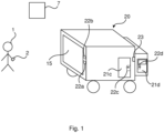
- Fig 1 is a schematic diagram illustrating an environment in which embodiments presented herein can be applied.
- a user 1 is a logistics person associated with a vehicle 20, for instance the currently assigned driver of the vehicle.
- the vehicle 20 is suitable for carrying cargo and can be a van, a lorry, a car, etc.
- the cargo can be loaded in the vehicle 20 e.g. in the form of boxes, optionally on pallets.
- the vehicle 20 is provided with a tail lift 15 and one or more cabin doors 21d (only one seen in Fig 1 ).
- a side door 21c for access to the cargo area of the vehicle is provided.
- the vehicle can comprise a trailer for which the tail lift and roller shutter can be controlled in the same manner as the tail lift 15 and roller shutter of the vehicle itself.
- a tail lift 15 secures the back of the vehicle.
- a first electronic lock 22a is provided to operate the tail lift.
- a second electronic lock 22b is provided to secure the operation of a roller shutter (not seen in Fig 1 but shown in Figs2A-B ).
- the cabin door(s) 21d are secured by a fourth electronic lock 22d and the optional side door 21c is secured by an optional third electronic lock 22c.
- an electronic access control device 23 controls access to operation of the vehicle, corresponding to an ignition key.
- the user 1 carries a wearable device 2.
- a wearable device 2 is an electronic device which can be worn by the user.
- the wearable device can be in the form of a wristband or watch.
- the wearable device 2 is used to identify the user 1 using biometric sensors.
- the user can request access to a physical space by placing the wearable device 2 in close proximity (e.g. centimetres) or in contact with a tag (not shown) associated with the electronic lock securing the physical space in question.
- the communication between the tag and the wearable device 2 can e.g. be based on RFID (Radio Frequency Identification) or NFC (Near Field Communication). This will trigger the electronic lock to perform an access control procedure for the user identified by the wearable device 2. If the access control procedure is positive, the electronic lock will be set in an unlocked state, allowing the user to access the physical space. The same procedure can be used to set the electronic lock in a locked state.
- the user can control the tail lift 15 using traditional controls (which are disabled when the first electronic lock is set in a locked state) or by means of a user interface on the wearable device 2.
- the tail lift 15 is lowered whenever the first electronic lock 22a is set in an unlocked state.
- the user can control the roller shutter using traditional controls (which are disabled when the first electronic lock is set in a locked state) or by means of a user interface on the wearable device 2.
- the shutter roller is opened whenever the second electronic lock 22b is set in an unlocked state.
- An access manager 7 is a computer which is used to allocate access to the user 1 as needed, to be able to open the electronic locks 22a-c as needed.
- the wearable device 2 can communicate with the access manager, e.g. using a cellular network module within the wearable device 2 or via a smartphone connected with the wearable device 2 over a short range wireless link.
- the user 1 reports to a logistics centre, at which the user 1 is assigned a vehicle and a delivery schedule for the day.
- the user accepts by identifying him/herself using the wearable device.
- the vehicle can be started only after the user has provided identification on the wearable device.
- the user Once the user arrives at a delivery location, the user exits the cabin and walks around to the back of the vehicle. The tail lift is lowered by the user providing identification on the wearable device. The roller shutter is opened in the same way. Once the user has picked up an item to be delivered, e.g. a parcel, the user exits the vehicle and closes the roller shutter by identifying using the wearable device.
- an item to be delivered e.g. a parcel
- an accelerometer in the vehicle is used to detect when the user has exited the vehicle, at which point roller shutter is closed and locked. This detection can be based on an absence of movement or based on movement which differs from a movement pattern of the user.
- the movement pattern of the user has in that case been calibrated in advance, by the user moving about the cargo space in the vehicle for 3-6 minutes when in a calibration mode.
- Figs 2A-B are schematic diagrams illustrating the use of a roller shutter 16 in the vehicle 20 of Fig 1 . The views are from the back of the vehicle 20. In both Fig 2A and Fig 2B , the tail lift 15 is lowered.
- roller shutter 16 is in a closed (and locked) state, preventing any unauthorised persons from entering the cargo area.
- the roller shutter 16 is here in a rolled down, protective state.
- roller shutter 16 is in an open state, whereby the cargo area can be accessed.
- the roller shutter 16 is here in a rolled up, open, state.
- the cargo area of the vehicle is thus secured not only by the tail lift, but also by the roller shutter.
- the roller shutter is closed and locked, while the tail lift can be left in an open position. This can be of great value, especially when the driver needs to go back and forth between the vehicle and the recipient (or adjacent recipients) several times.
- Fig 3 is a schematic cross section of the roller shutter of Figs 2A-B with a connected controller.
- a protective barrier 17 provides physical protection and is very difficult for an attacker to penetrate.
- the protective barrier 17 can be made by metal and/or reinforced plastic.
- the protective barrier 17 can optionally be made in a material which is thermally insulating, e.g. to keep a refrigerated cargo area cool.
- the roller shutter 16 also comprises a mesh 18 of conductors being attached to the protective barrier.
- the conductor can be wires which stay functional during normal use but break easily when the protective barrier 17 is physically broken.
- the mesh 18 covers the entire area of the roller shutter when closed, see Fig 2A .
- a processor 60 is connected to the mesh 18. In this way, if an attacker manager to penetrate the protective barrier 17, the mesh 18 is also broken, which is detected by the processor 60. This is detected by a variation in impedance greater than a threshold variation, when the impedance is measured between two opposite sides of the mesh 18.
- Fig 4 is a schematic diagram illustrating an embodiment of a wearable device 2 of Fig 1 in the form of a wristband.
- the wearable device 2 comprises a first biometric sensor 3a for obtaining first biometric data and a second biometric sensor 3b for obtaining second biometric data.
- the second biometric sensor 3b captures second biometric data comprising a finger pressure parameter.
- the wearable device 2 is configured to determine an identity of the user 1 based on the first biometric data and the second biometric data.
- the finger pressure parameter can be a curve of how the finger pressure varies over time, which improves the accuracy of identifying the user.
- the specific finger pressure pattern for the user needs to be captured initially, and may need to be periodically calibrated over time.
- the wearable device 2 is in the form of a wristband, to be worn around the wrist of the user.
- the first biometric sensor 3a can be a fingerprint sensor. This allows for convenient identification of the user, e.g. by comparing a captured fingerprint with one or more templates.
- the first biometric sensor 3a is a blood flow sensor.
- the blood flow sensor captures the blood flow, which varies over time in a user specific manner. Hence, the blood flow over time can be compared with blood flow templates to determine an identity of the user. Since the first biometric sensor 3a is used for finger pressure detection, the user needs to press the wearable device towards the body. This increases the quality of blood flow capturing.
- the first biometric sensor 3a is a voice recognition unit.
- the spoken voice of a user is then captured using a microphone.
- the captured voice can be compared with voice templates to determine an identity of the user.
- the first biometric sensor 3a is an iris recognition unit.
- the iris of a user is then captured using a camera.
- the captured iris can be compared with iris templates to determine an identity of the user.
- the iris recognition unit can form part of the wearable device, or a rear vision camera of the vehicle can be used for this biometric sensor.
- the first biometric sensor 3a is an face recognition unit.
- the face of a user is then captured using a camera.
- the captured face can be compared with face templates to determine an identity of the user.
- the face recognition unit can form part of the wearable device, or a rear vision camera of the vehicle can be used for this biometric sensor.
- the first biometric sensor 3a is an accelerometer, optionally combined with a gyro.
- the movement pattern of a user is then captured using the accelerometer and optionally the gyro.
- the captured movement patter can be compared with movement templates to determine an identity of the user.
- the first biometric sensor 3a is a breathalyser. Presence and/or extent of components of expired air of a user is then captured. The captured presence and/or extent of components can be compared with templates to determine an identity of the user.
- the first biometric sensor 3a can comprise any suitable sensor for sensing a biometric of the user.
- additional biometric sensors can be added to further improve accuracy of user identifications. More sensors imply reduces risk of false positive and false negative identifications.
- Fig 5 is a schematic diagram illustrating components of the roller shutter 16 of Figs 2A-B .
- a processor 60 is provided using any combination of one or more of a suitable central processing unit (CPU), multiprocessor, microcontroller, digital signal processor (DSP), application specific integrated circuit etc., capable of executing software instructions 67 stored in a memory 64, which can thus be a computer program product.
- the processor 60 can be configured to execute the method described with reference to Fig 6 below.
- the memory 64 can be any combination of random access memory (RAM) and read only memory (ROM).
- the memory 64 also comprises persistent storage, which, for example, can be any single one or combination of magnetic memory, optical memory, solid-state memory or even remotely mounted memory.
- a data memory 66 is also provided for reading and/or storing data during execution of software instructions in the processor 60.
- the data memory 66 can be any combination of random access memory (RAM) and read only memory (ROM).
- RAM random access memory
- ROM read only memory
- the data memory 66 can e.g. comprise templates for biometric identification of a user.
- the roller shutter 16 further comprises an I/O interface 62 for communicating with other external entities.
- the I/O interface 62 also includes a user interface.
- An electric motor 68 controls transitions of the protective barrier 17 (and the mesh 18) between rolled up and rolled down states (or any state in between), controlled by the processor 60.
- the processor 60 is connected to the mesh 18 to detect if the integrity of the mesh is compromised in any way, e.g. if it is broken.
- roller shutter 16 Other components of the roller shutter 16 are omitted in order not to obscure the concepts presented herein.
- Fig 6 is a flow chart illustrating a method for securing a physical space within a vehicle, performed in the roller shutter of Figs 2A-B .
- a valid open request is determined based on a signal from an electronic lock that access is granted. This can e.g. be a signal from the second electronic lock.
- an open roller shutter step 42 the roller shutter is opened when the valid open request is determined. This opening is effected by controlling the motor of the roller shutter to wind up the roller shutter.
- step 44 it is determined when a user has exited the vehicle.
- This determination is based on a signal from an accelerometer attached to the vehicle or this determination is based on a signal from an accelerometer attached to the user.
- a close roller shutter step 46 the roller shutter is closed (to a closed and locked state). This occurs when the user exit has been determined. This closing is effected by controlling the motor of the roller shutter to wind down the roller shutter.
- a physical break in a mesh of the conductors is detected.
- the physical break is detected as a variation in impedance greater than a threshold variation.
- a signal break-in step 52 signalling that a break-in is detected is performed when a break in the mesh of conductors is connected.
- the signalling can result in a siren being activated by the vehicle and/or that a central office is notified that a break-in is detected.
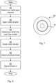
- Fig 7 shows one example of a computer program product comprising computer readable means.
- a computer program 91 can be stored, which computer program can cause a processor to execute a method according to embodiments described herein.
- the computer program product is an optical disc, such as a CD (compact disc) or a DVD (digital versatile disc) or a Blu-Ray disc.
- the computer program product could also be embodied in a memory of a device, such as the computer program product 64 of Fig 4 .
- the computer program 91 is here schematically shown as a track on the depicted optical disk, the computer program can be stored in any way which is suitable for the computer program product, such as a removable solid state memory, e.g. a Universal Serial Bus (USB) drive.
- USB Universal Serial Bus
Landscapes
- Engineering & Computer Science (AREA)
- Physics & Mathematics (AREA)
- General Physics & Mathematics (AREA)
- Mechanical Engineering (AREA)
- Computer Security & Cryptography (AREA)
- Business, Economics & Management (AREA)
- Emergency Management (AREA)
- Operating, Guiding And Securing Of Roll- Type Closing Members (AREA)
- Lock And Its Accessories (AREA)
- Power-Operated Mechanisms For Wings (AREA)
Description
- The invention relates to a roller shutter for securing a physical space within a vehicle and corresponding vehicle, method, computer program and computer program product.
- With online shopping steadily increasing, deliveries of physical goods are also increasing. Consumers want fast and cheap delivery and the delivery companies want efficiency and safety for their deliveries.
- Thefts from delivery vehicles and attacks against drivers are increasing since the value of the goods increases.
- Drivers have very busy routes with many stops. Current security solutions for delivery vehicles rely on traditional vehicle locks or even padlocks. It is very inconvenient for the drivers to secure the vehicle each time a delivery takes place. Moreover, the detection of a break-in is often not reliable.
- A example for an apparatus for providing security for a lorry comprising closure means is provided in
WO 03/024755 - It is an object to provide better and more convenient security for cargo vehicles. The invention is defined by
independent claims 1,4 and 6. - According to a first aspect, it is provided a roller shutter for securing a physical space within a vehicle. The roller shutter comprises: a protective barrier configured to be in a rolled up, open, state, and in a rolled down, protective state; a mesh of conductors being attached to the protective barrier; a processor; and a memory storing instructions that, when executed by the processor, cause the roller shutter to: detect a physical break in the mesh of conductors; when a break in the mesh of conductors is connected, signal that a break-in is detected; determine a valid open request; open the roller shutter when the valid open request is determined; determine when a user has exited the vehicle; and close the roller shutter when the user exit has been determined.
- The mesh of conductors may comprise a mesh of wires.
- The instructions to determine when a user has exited the vehicle are based on a signal from an accelerometer attached to the vehicle or are based on a signal from an accelerometer attached to the user.
- According to a second aspect, it is provided a vehicle comprising the roller shutter according to any one of the preceding claims.
- According to a third aspect, it is provided a method for securing a physical space within a vehicle using a roller shutter. The roller shutter comprises a protective barrier configured to be in a rolled up, open, state, and in a rolled down, protective state. The roller shutter further comprises a mesh of conductors being attached to the protective barrier. The method comprises the steps of: detecting a physical break in the mesh of the conductors; signalling that a break-in is detected when a break in the mesh of conductors is connected; determining a valid open request; opening the roller shutter when the valid open request is determined; determining when a user has exited the vehicle; and closing the roller shutter when the user exit has been determined.
- The mesh of conductors may comprise a mesh of wires.
- The method may further comprise the steps of: determining a valid open request; opening the roller shutter when the valid open request is determined; determining when a user has exited the vehicle; and closing the roller shutter when the user exit has been determined.
- The step of determining when a user has exited the vehicle is be based on a signal from an accelerometer attached to the vehicle or is based on a signal from an accelerometer attached to the user.
- According to a fourth aspect, it is provided a computer program for securing a physical space within a vehicle using a roller shutter. The roller shutter comprises a protective barrier configured to be in a rolled up, open, state, and in a rolled down, protective state, and a mesh of conductors being attached to the protective barrier. The computer program comprises computer program code which, when run on a roller shutter causes the roller shutter to: detect a physical break in the mesh of conductors; signal that a break-in is detected when a break in the mesh of conductors is connected; determine a valid open request; open the roller shutter when the valid open request is determined; determine when a user has exited the vehicle; and close the roller shutter when the user exit has been determined.
- According to a fifth aspect, it is provided a computer program product comprising a computer program according to the fourth aspect and a computer readable means on which the computer program is stored. Generally, all terms used in the claims are to be interpreted according to their ordinary meaning in the technical field, unless explicitly defined otherwise herein. All references to "a/an/the element, apparatus, component, means, step, etc." are to be interpreted openly as referring to at least one instance of the element, apparatus, component, means, step, etc., unless explicitly stated otherwise. The steps of any method disclosed herein do not have to be performed in the exact order disclosed, unless explicitly stated.
- The invention is now described, by way of example, with reference to the accompanying drawings, in which:
-
Fig 1 is a schematic diagram illustrating an environment in which embodiments presented herein can be applied; -
Figs 2A-B are schematic diagrams illustrating the use of a roller shutter in the vehicle ofFig 1 ; -
Fig 3 is a schematic cross section of the roller shutter ofFigs 2A-B with a connected controller; -
Fig 4 is a schematic diagram illustrating an embodiment of a wearable device ofFig 1 ; -
Fig 5 is a schematic diagram illustrating components of the roller shutter ofFigs 2A-B ; -
Fig 6 is a flow chart illustrating a method for securing a physical space within a vehicle, performed in the roller shutter ofFigs 2A-B ; and -
Fig 7 shows one example of a computer program product comprising computer readable means. - The invention will now be described more fully hereinafter with reference to the accompanying drawings, in which certain embodiments of the invention are shown. This invention may, however, be embodied in many different forms and should not be construed as limited to the embodiments set forth herein; rather, these embodiments are provided by way of example so that this disclosure will be thorough and complete, and will fully convey the scope of the invention to those skilled in the art. Like numbers refer to like elements throughout the description.
- Embodiments presented herein are based on the idea that the cargo area of a vehicle is secured not only by a tail lift, but also by a roller shutter. In this way, when the user (e.g. driver) leaves the vehicle for a delivery, it is sufficient if the roller shutter is closed and locked, while the tail lift can be left in an open position. This can be of great value, especially when the driver needs to go back and forth between the vehicle and the delivery address several times.
-
Fig 1 is a schematic diagram illustrating an environment in which embodiments presented herein can be applied. - A
user 1 is a logistics person associated with avehicle 20, for instance the currently assigned driver of the vehicle. Thevehicle 20 is suitable for carrying cargo and can be a van, a lorry, a car, etc. The cargo can be loaded in thevehicle 20 e.g. in the form of boxes, optionally on pallets. - The
vehicle 20 is provided with atail lift 15 and one ormore cabin doors 21d (only one seen inFig 1 ). Optionally, aside door 21c for access to the cargo area of the vehicle is provided. It is to be noted that the vehicle can comprise a trailer for which the tail lift and roller shutter can be controlled in the same manner as thetail lift 15 and roller shutter of the vehicle itself. - A
tail lift 15 secures the back of the vehicle. To operate the tail lift, a firstelectronic lock 22a is provided. A secondelectronic lock 22b is provided to secure the operation of a roller shutter (not seen inFig 1 but shown inFigs2A-B ). The cabin door(s) 21d are secured by a fourthelectronic lock 22d and theoptional side door 21c is secured by an optional thirdelectronic lock 22c. Optionally, an electronicaccess control device 23 controls access to operation of the vehicle, corresponding to an ignition key. - The
user 1 carries awearable device 2. Awearable device 2 is an electronic device which can be worn by the user. For instance the wearable device can be in the form of a wristband or watch. As explained in more detail below, thewearable device 2 is used to identify theuser 1 using biometric sensors. The user can request access to a physical space by placing thewearable device 2 in close proximity (e.g. centimetres) or in contact with a tag (not shown) associated with the electronic lock securing the physical space in question. The communication between the tag and thewearable device 2 can e.g. be based on RFID (Radio Frequency Identification) or NFC (Near Field Communication). This will trigger the electronic lock to perform an access control procedure for the user identified by thewearable device 2. If the access control procedure is positive, the electronic lock will be set in an unlocked state, allowing the user to access the physical space. The same procedure can be used to set the electronic lock in a locked state. - When the first
electronic lock 22a is set in an unlocked state, the user can control thetail lift 15 using traditional controls (which are disabled when the first electronic lock is set in a locked state) or by means of a user interface on thewearable device 2. Optionally, thetail lift 15 is lowered whenever the firstelectronic lock 22a is set in an unlocked state. - When the second
electronic lock 22b is set in an unlocked state, the user can control the roller shutter using traditional controls (which are disabled when the first electronic lock is set in a locked state) or by means of a user interface on thewearable device 2. Optionally, the shutter roller is opened whenever the secondelectronic lock 22b is set in an unlocked state. - An
access manager 7 is a computer which is used to allocate access to theuser 1 as needed, to be able to open theelectronic locks 22a-c as needed. Thewearable device 2 can communicate with the access manager, e.g. using a cellular network module within thewearable device 2 or via a smartphone connected with thewearable device 2 over a short range wireless link. - A usage scenario in the environment illustrated in
Fig 1 will now be described. - At the start of a shift, the
user 1 reports to a logistics centre, at which theuser 1 is assigned a vehicle and a delivery schedule for the day. The user accepts by identifying him/herself using the wearable device. - Optionally, the vehicle can be started only after the user has provided identification on the wearable device.
- Once the user arrives at a delivery location, the user exits the cabin and walks around to the back of the vehicle. The tail lift is lowered by the user providing identification on the wearable device. The roller shutter is opened in the same way. Once the user has picked up an item to be delivered, e.g. a parcel, the user exits the vehicle and closes the roller shutter by identifying using the wearable device.
- Alternatively, an accelerometer in the vehicle is used to detect when the user has exited the vehicle, at which point roller shutter is closed and locked. This detection can be based on an absence of movement or based on movement which differs from a movement pattern of the user. The movement pattern of the user has in that case been calibrated in advance, by the user moving about the cargo space in the vehicle for 3-6 minutes when in a calibration mode.
- Alternatively, the roller shutter is closed every time it is closed. The cabin doors can be locked automatically when the roller shutter is closed.
Figs 2A-B are schematic diagrams illustrating the use of aroller shutter 16 in thevehicle 20 ofFig 1 . The views are from the back of thevehicle 20. In bothFig 2A and Fig 2B , thetail lift 15 is lowered. - In
Fig 2A , theroller shutter 16 is in a closed (and locked) state, preventing any unauthorised persons from entering the cargo area. Theroller shutter 16 is here in a rolled down, protective state. - In
Fig 2B , theroller shutter 16 is in an open state, whereby the cargo area can be accessed. Theroller shutter 16 is here in a rolled up, open, state. - The cargo area of the vehicle is thus secured not only by the tail lift, but also by the roller shutter. In this way, when the user (e.g. driver) leaves the vehicle for a delivery, it is sufficient if the roller shutter is closed and locked, while the tail lift can be left in an open position. This can be of great value, especially when the driver needs to go back and forth between the vehicle and the recipient (or adjacent recipients) several times. Moreover, there is less mechanical wear on the tail lift when this does not need to be used to secure the cargo area.
-
Fig 3 is a schematic cross section of the roller shutter ofFigs 2A-B with a connected controller. Aprotective barrier 17 provides physical protection and is very difficult for an attacker to penetrate. Theprotective barrier 17 can be made by metal and/or reinforced plastic. Theprotective barrier 17 can optionally be made in a material which is thermally insulating, e.g. to keep a refrigerated cargo area cool. - The
roller shutter 16 also comprises amesh 18 of conductors being attached to the protective barrier. The conductor can be wires which stay functional during normal use but break easily when theprotective barrier 17 is physically broken. Themesh 18 covers the entire area of the roller shutter when closed, seeFig 2A . Moreover, aprocessor 60 is connected to themesh 18. In this way, if an attacker manager to penetrate theprotective barrier 17, themesh 18 is also broken, which is detected by theprocessor 60. This is detected by a variation in impedance greater than a threshold variation, when the impedance is measured between two opposite sides of themesh 18. -
Fig 4 is a schematic diagram illustrating an embodiment of awearable device 2 ofFig 1 in the form of a wristband. Thewearable device 2 comprises a firstbiometric sensor 3a for obtaining first biometric data and a secondbiometric sensor 3b for obtaining second biometric data. The secondbiometric sensor 3b captures second biometric data comprising a finger pressure parameter. - The
wearable device 2 is configured to determine an identity of theuser 1 based on the first biometric data and the second biometric data. - By measuring the finger pressure, an additional biometric parameter is captured which is difficult to copy and easy for the user to remember. The finger pressure parameter can be a curve of how the finger pressure varies over time, which improves the accuracy of identifying the user. The specific finger pressure pattern for the user needs to be captured initially, and may need to be periodically calibrated over time.
- In this embodiment, the
wearable device 2 is in the form of a wristband, to be worn around the wrist of the user. - The first
biometric sensor 3a can be a fingerprint sensor. This allows for convenient identification of the user, e.g. by comparing a captured fingerprint with one or more templates. - Optionally, the first
biometric sensor 3a is a blood flow sensor. The blood flow sensor captures the blood flow, which varies over time in a user specific manner. Hence, the blood flow over time can be compared with blood flow templates to determine an identity of the user. Since the firstbiometric sensor 3a is used for finger pressure detection, the user needs to press the wearable device towards the body. This increases the quality of blood flow capturing. - Optionally, the first
biometric sensor 3a is a voice recognition unit. The spoken voice of a user is then captured using a microphone. The captured voice can be compared with voice templates to determine an identity of the user. - Optionally, the first
biometric sensor 3a is an iris recognition unit. The iris of a user is then captured using a camera. The captured iris can be compared with iris templates to determine an identity of the user. The iris recognition unit can form part of the wearable device, or a rear vision camera of the vehicle can be used for this biometric sensor. - Optionally, the first
biometric sensor 3a is an face recognition unit. The face of a user is then captured using a camera. The captured face can be compared with face templates to determine an identity of the user. The face recognition unit can form part of the wearable device, or a rear vision camera of the vehicle can be used for this biometric sensor. - Optionally, the first
biometric sensor 3a is an accelerometer, optionally combined with a gyro. The movement pattern of a user is then captured using the accelerometer and optionally the gyro. The captured movement patter can be compared with movement templates to determine an identity of the user. - Optionally, the first
biometric sensor 3a is a breathalyser. Presence and/or extent of components of expired air of a user is then captured. The captured presence and/or extent of components can be compared with templates to determine an identity of the user. - Hence, the first
biometric sensor 3a can comprise any suitable sensor for sensing a biometric of the user. Optionally, additional biometric sensors can be added to further improve accuracy of user identifications. More sensors imply reduces risk of false positive and false negative identifications. -
Fig 5 is a schematic diagram illustrating components of theroller shutter 16 ofFigs 2A-B . Aprocessor 60 is provided using any combination of one or more of a suitable central processing unit (CPU), multiprocessor, microcontroller, digital signal processor (DSP), application specific integrated circuit etc., capable of executingsoftware instructions 67 stored in amemory 64, which can thus be a computer program product. Theprocessor 60 can be configured to execute the method described with reference toFig 6 below. - The
memory 64 can be any combination of random access memory (RAM) and read only memory (ROM). Thememory 64 also comprises persistent storage, which, for example, can be any single one or combination of magnetic memory, optical memory, solid-state memory or even remotely mounted memory. - A
data memory 66 is also provided for reading and/or storing data during execution of software instructions in theprocessor 60. Thedata memory 66 can be any combination of random access memory (RAM) and read only memory (ROM). Thedata memory 66 can e.g. comprise templates for biometric identification of a user. - The
roller shutter 16 further comprises an I/O interface 62 for communicating with other external entities. Optionally, the I/O interface 62 also includes a user interface. - An
electric motor 68 controls transitions of the protective barrier 17 (and the mesh 18) between rolled up and rolled down states (or any state in between), controlled by theprocessor 60. Theprocessor 60 is connected to themesh 18 to detect if the integrity of the mesh is compromised in any way, e.g. if it is broken. - Other components of the
roller shutter 16 are omitted in order not to obscure the concepts presented herein. -
Fig 6 is a flow chart illustrating a method for securing a physical space within a vehicle, performed in the roller shutter ofFigs 2A-B . - In a determine valid
open request step 40, a valid open request is determined based on a signal from an electronic lock that access is granted. This can e.g. be a signal from the second electronic lock. - In an open
roller shutter step 42, the roller shutter is opened when the valid open request is determined. This opening is effected by controlling the motor of the roller shutter to wind up the roller shutter. - In a determine when the user has exited
step 44, it is determined when a user has exited the vehicle. - This determination is based on a signal from an accelerometer attached to the vehicle or this determination is based on a signal from an accelerometer attached to the user.
- In a close
roller shutter step 46, the roller shutter is closed (to a closed and locked state). This occurs when the user exit has been determined. This closing is effected by controlling the motor of the roller shutter to wind down the roller shutter. - In a detect
physical break step 50, a physical break in a mesh of the conductors is detected. The physical break is detected as a variation in impedance greater than a threshold variation. - In a signal break-
in step 52, signalling that a break-in is detected is performed when a break in the mesh of conductors is connected. The signalling can result in a siren being activated by the vehicle and/or that a central office is notified that a break-in is detected. -
Fig 7 shows one example of a computer program product comprising computer readable means. On this computer readable means, acomputer program 91 can be stored, which computer program can cause a processor to execute a method according to embodiments described herein. In this example, the computer program product is an optical disc, such as a CD (compact disc) or a DVD (digital versatile disc) or a Blu-Ray disc. As explained above, the computer program product could also be embodied in a memory of a device, such as thecomputer program product 64 ofFig 4 . While thecomputer program 91 is here schematically shown as a track on the depicted optical disk, the computer program can be stored in any way which is suitable for the computer program product, such as a removable solid state memory, e.g. a Universal Serial Bus (USB) drive. - The invention has mainly been described above with reference to a few embodiments. However, as is readily appreciated by a person skilled in the art, other embodiments than the ones disclosed above are equally possible within the scope of the invention, as defined by the appended patent claims.
Claims (7)
- A roller shutter (16) for securing a physical space within a vehicle, the roller shutter comprising:a protective barrier (17) configured to be either in a rolled up, open, state, or in a rolled down, protective state;an electric motor (68) configured to control transitions of the protective barrier (17) between the rolled up and the rolled down states, or any state in between;a mesh (18) of conductors being attached to the protective barrier;a processor (60); anda memory (64) storing instructions (67) that, when executed by the processor, cause the roller shutter to:detect a physical break in the mesh of conductors by detecting a variation in impedance greater than a threshold variation when the impedance is measured between two opposite sides of the mesh (18);when a break in the mesh of conductors is detected, signal that a break-in is detected;determine a valid open request based on a signal from an electronic lock that access is granted;open the protective barrier of the roller shutter by controlling the motor of the roller shutter to wind up the roller shutter when the valid open request is determined;determine when a user has exited the physical space within the vehicle based on a signal from an accelerometer attached to the vehicle or a signal from an accelerometer attached to the user; andclose the protective barrier of the roller shutter by controlling the motor of the roller shutter to wind down the roller shutter when the user exit has been determined.
- The roller shutter (16) according to claim 1, wherein the mesh (18) of conductors comprises a mesh of wires.
- A vehicle (20) comprising the roller shutter according to any one of the preceding claims.
- A method for securing a physical space within a vehicle using a roller shutter comprising a protective barrier configured to be either in a rolled up, open, state, or in a rolled down, protective state, an electric motor (68) configured to control transitions of the protective barrier (17) between the rolled up and the rolled down states, or any state in between; and a mesh (18) of conductors being attached to the protective barrier, the method being performed by the roller shutter (16) and comprising the steps of:detecting (50) a physical break in the mesh (18) of the conductors by detecting a variation in impedance greater than a threshold variation when the impedance is measured between two opposite sides of the mesh (18);signalling (52) that a break-in is detected when a break in the mesh of conductors is detected;determining (40) a valid open request based on a signal from an electronic lock that access is granted;opening (42) the protective barrier of the roller shutter by controlling the motor of the roller shutter to wind up the roller shutter when the valid open request is determined;determining (44) when a user has exited the physical space within the vehicle based on a signal from an accelerometer attached to the vehicle or a signal from an accelerometer attached to the user; andclosing (46) the protective barrier of the roller shutter by controlling the motor of the roller shutter to wind down the roller shutter when the user exit has been determined.
- The method according to claim 4, wherein the mesh (18) of conductors comprises a mesh of wires.
- A computer program (67, 91) for securing a physical space within a vehicle using a roller shutter comprising a protective barrier configured to be either in a rolled up, open, state, or in a rolled down, protective state, an electric motor (68) configured to control transitions of the protective barrier (17) between the rolled up and the rolled down states, or any state in between and a mesh (18) of conductors being attached to the protective barrier; the computer program comprising computer program code which, when run on a roller shutter causes the roller shutter to:detect a physical break in the mesh (18) of conductors by detecting a variation in impedance greater than a threshold variation when the impedance is measured between two opposite sides of the mesh (18);signal that a break-in is detected when a break in the mesh of conductors is detected;determine a valid open request based on a signal from an electronic lock that access is granted;open the protective barrier of the roller shutter by controlling the motor of the roller shutter to wind up the roller shutter when the valid open request is determined;determine when a user has exited the physical space within the vehicle based on a signal from an accelerometer attached to the vehicle or a signal from an accelerometer attached to the user; andclose the protective barrier of the roller shutter by controlling the motor of the roller shutter to wind down the roller shutter when the user exit has been determined.
- A computer program product (64, 90) comprising a computer program according to claim 6 and a computer readable means on which the computer program is stored.
Applications Claiming Priority (2)
| Application Number | Priority Date | Filing Date | Title |
|---|---|---|---|
| EP17198095 | 2017-10-24 | ||
| PCT/EP2018/078985 WO2019081478A1 (en) | 2017-10-24 | 2018-10-23 | Roller shutter for securing a physical space within a vehicle |
Publications (2)
| Publication Number | Publication Date |
|---|---|
| EP3701506A1 EP3701506A1 (en) | 2020-09-02 |
| EP3701506B1 true EP3701506B1 (en) | 2023-07-19 |
Family
ID=60186052
Family Applications (1)
| Application Number | Title | Priority Date | Filing Date |
|---|---|---|---|
| EP18786815.3A Active EP3701506B1 (en) | 2017-10-24 | 2018-10-23 | Roller shutter for securing a physical space within a vehicle |
Country Status (4)
| Country | Link |
|---|---|
| US (1) | US11624230B2 (en) |
| EP (1) | EP3701506B1 (en) |
| CN (1) | CN111247570B (en) |
| WO (1) | WO2019081478A1 (en) |
Family Cites Families (24)
| Publication number | Priority date | Publication date | Assignee | Title |
|---|---|---|---|---|
| US3952566A (en) * | 1975-03-03 | 1976-04-27 | Sperry Rand Corporation | Bearing and lubricant film test method and apparatus |
| DE2628766A1 (en) * | 1976-06-26 | 1978-01-05 | Ernst Woelm | Burglar alarm system for windows - uses roller blind with inlaid fine wires forming closed circuit with alarm circuit |
| DE3267675D1 (en) * | 1981-07-06 | 1986-01-09 | Joergensen Poul Richter | Alarm system for safeguarding against the breakthrough of a surface |
| WO1987006749A1 (en) | 1986-05-03 | 1987-11-05 | Adrian Francis Wolf | Alarm system |
| US5274357A (en) * | 1992-02-05 | 1993-12-28 | Riordan Dennis E | Combined alarm system and window covering assembly |
| GB8703559D0 (en) | 1987-02-16 | 1987-03-25 | Westinghouse Brake & Signal | Operating door/brake |
| US5049854A (en) * | 1990-03-08 | 1991-09-17 | Wolf Adrian F | Sensing element for an alarm system |
| DE4008441A1 (en) * | 1990-03-16 | 1991-09-19 | Rolf Prettl | Roller shutter with transverse slats in side guides - has current conductors on slats coupled to alarm for protection against intruder |
| US5686909A (en) | 1996-06-05 | 1997-11-11 | Steinhauser; Louis P. | Alarm system for boat covers and automobile convertible tops |
| GB0122541D0 (en) * | 2001-09-19 | 2001-11-07 | Froud Sheila M | Commercial vehicle trailer side curtains customised to become security curtains |
| AU2003233868A1 (en) * | 2002-04-29 | 2003-11-17 | Tiss Limited | Security system for vehicles |
| DE10232244B4 (en) | 2002-07-17 | 2005-03-10 | Huf Huelsbeck & Fuerst Gmbh | Locking system for a door, flap o. The like., Especially for vehicles |
| GB0914561D0 (en) * | 2009-08-20 | 2009-09-30 | Hird James A R | Security system |
| CN202728373U (en) | 2012-07-17 | 2013-02-13 | 青州泰联电气有限公司 | Light truck trunk with remote control shutter trunk door |
| CN103114797B (en) | 2012-12-08 | 2015-08-26 | 李志锋 | A kind of anti-theft warning rolling curtain door |
| US9834984B2 (en) * | 2013-10-31 | 2017-12-05 | Fibar Group S.A. | Roller shutter controller |
| US9739226B2 (en) | 2014-02-07 | 2017-08-22 | Ford Global Technologies, Llc | Walk-away vehicle shutdown |
| CN104933781A (en) * | 2014-03-21 | 2015-09-23 | 比亚迪股份有限公司 | Automatic locking system and method for vehicle |
| EP3253603B1 (en) | 2015-02-04 | 2021-03-24 | Assa Abloy Entrance Systems AB | Cargo transportation housing comprising a flexible fast door |
| CN105649512A (en) | 2016-03-09 | 2016-06-08 | 江苏安永智能科技有限公司 | Intelligent anti-theft system |
| CN206568856U (en) | 2017-03-29 | 2017-10-20 | 张伯仁 | Electric rolling curtain closed lorry body door |
| US20180361831A1 (en) * | 2017-06-14 | 2018-12-20 | Ford Global Technologies, Llc | Vehicle shade assembly |
| US20200090425A1 (en) * | 2018-09-18 | 2020-03-19 | Cambridge Mobile Telematics Inc. | Using vehicle electrical system monitored values |
| US11492838B2 (en) * | 2019-09-15 | 2022-11-08 | Systems, LLC | System and method for controlling movable barrier operation at a secured premises |
-
2018
- 2018-10-23 EP EP18786815.3A patent/EP3701506B1/en active Active
- 2018-10-23 US US16/756,751 patent/US11624230B2/en active Active
- 2018-10-23 CN CN201880068831.9A patent/CN111247570B/en active Active
- 2018-10-23 WO PCT/EP2018/078985 patent/WO2019081478A1/en not_active Ceased
Also Published As
| Publication number | Publication date |
|---|---|
| EP3701506A1 (en) | 2020-09-02 |
| US11624230B2 (en) | 2023-04-11 |
| CN111247570A (en) | 2020-06-05 |
| CN111247570B (en) | 2022-04-05 |
| US20210189789A1 (en) | 2021-06-24 |
| WO2019081478A1 (en) | 2019-05-02 |
Similar Documents
| Publication | Publication Date | Title |
|---|---|---|
| US20130249669A1 (en) | Method and device for opening and closing a door and/or a tailgate of a vehicle | |
| US11887459B2 (en) | Wearable device with multibiometry | |
| CN102232228A (en) | Device for automatically unlocking an openable panel of a motor vehicle | |
| US20110210821A1 (en) | Device for automatically unlocking an openable panel of a motor vehicle | |
| CN105059243A (en) | Automatic automobile door and window locking system and method | |
| KR101617872B1 (en) | Alert method and system of fingerprint reader | |
| CN104968532A (en) | Vehicle electromechanical systems triggering based on image recognition and radio frequency | |
| WO2005124669A3 (en) | Radio identification with an additional close-range check | |
| EP3349191A1 (en) | Method and system for automatically activating a closing element of a closable opening of a vehicle | |
| JP2009035994A (en) | Article management system, article management method, vehicle management system, and vehicle management method | |
| EP3701506B1 (en) | Roller shutter for securing a physical space within a vehicle | |
| CN110712606B (en) | In-vehicle life recognition method, device, equipment and storage medium | |
| KR20150015556A (en) | Vehicle Strongbox Apparatus Using NFC and Method thereof | |
| EP3701504B1 (en) | Requesting access to a physical space controlled by an electronic lock associated with a tag | |
| KR101249940B1 (en) | Gate management system and method thereof | |
| JP2013242831A (en) | Room entry/exit management system and method | |
| KR102764269B1 (en) | Apparatus for controlling safety unlock of vehicle and method thereof | |
| US20130199095A1 (en) | Crime prevention device, crime prevention system and method for determining state of opening/closing body | |
| RU165926U1 (en) | ELECTRONIC ACCESS DEVICE FOR VEHICLE SAFETY SYSTEM | |
| JP6355498B2 (en) | Entrance / exit management system | |
| JP2024128295A (en) | Vehicle lock control device and vehicle lock control method | |
| IOANA et al. | Vehicle Security and Safety Systems | |
| CN101520927B (en) | Mobile cash collection vehicle self-service operation and security system | |
| KR20190071052A (en) | Apparatus and method for controlling object detectinn object, vehicle system | |
| JP2008107961A (en) | Vehicle approaching suspicious object detection system |
Legal Events
| Date | Code | Title | Description |
|---|---|---|---|
| STAA | Information on the status of an ep patent application or granted ep patent |
Free format text: STATUS: UNKNOWN |
|
| STAA | Information on the status of an ep patent application or granted ep patent |
Free format text: STATUS: THE INTERNATIONAL PUBLICATION HAS BEEN MADE |
|
| PUAI | Public reference made under article 153(3) epc to a published international application that has entered the european phase |
Free format text: ORIGINAL CODE: 0009012 |
|
| STAA | Information on the status of an ep patent application or granted ep patent |
Free format text: STATUS: REQUEST FOR EXAMINATION WAS MADE |
|
| 17P | Request for examination filed |
Effective date: 20200421 |
|
| AK | Designated contracting states |
Kind code of ref document: A1 Designated state(s): AL AT BE BG CH CY CZ DE DK EE ES FI FR GB GR HR HU IE IS IT LI LT LU LV MC MK MT NL NO PL PT RO RS SE SI SK SM TR |
|
| AX | Request for extension of the european patent |
Extension state: BA ME |
|
| DAV | Request for validation of the european patent (deleted) | ||
| DAX | Request for extension of the european patent (deleted) | ||
| STAA | Information on the status of an ep patent application or granted ep patent |
Free format text: STATUS: EXAMINATION IS IN PROGRESS |
|
| 17Q | First examination report despatched |
Effective date: 20210510 |
|
| GRAP | Despatch of communication of intention to grant a patent |
Free format text: ORIGINAL CODE: EPIDOSNIGR1 |
|
| STAA | Information on the status of an ep patent application or granted ep patent |
Free format text: STATUS: GRANT OF PATENT IS INTENDED |
|
| INTG | Intention to grant announced |
Effective date: 20230209 |
|
| GRAS | Grant fee paid |
Free format text: ORIGINAL CODE: EPIDOSNIGR3 |
|
| GRAA | (expected) grant |
Free format text: ORIGINAL CODE: 0009210 |
|
| STAA | Information on the status of an ep patent application or granted ep patent |
Free format text: STATUS: THE PATENT HAS BEEN GRANTED |
|
| P01 | Opt-out of the competence of the unified patent court (upc) registered |
Effective date: 20230530 |
|
| AK | Designated contracting states |
Kind code of ref document: B1 Designated state(s): AL AT BE BG CH CY CZ DE DK EE ES FI FR GB GR HR HU IE IS IT LI LT LU LV MC MK MT NL NO PL PT RO RS SE SI SK SM TR |
|
| REG | Reference to a national code |
Ref country code: GB Ref legal event code: FG4D |
|
| REG | Reference to a national code |
Ref country code: CH Ref legal event code: EP |
|
| REG | Reference to a national code |
Ref country code: DE Ref legal event code: R096 Ref document number: 602018053688 Country of ref document: DE |
|
| REG | Reference to a national code |
Ref country code: IE Ref legal event code: FG4D |
|
| PGFP | Annual fee paid to national office [announced via postgrant information from national office to epo] |
Ref country code: GB Payment date: 20230907 Year of fee payment: 6 |
|
| REG | Reference to a national code |
Ref country code: LT Ref legal event code: MG9D |
|
| REG | Reference to a national code |
Ref country code: NL Ref legal event code: MP Effective date: 20230719 |
|
| PGFP | Annual fee paid to national office [announced via postgrant information from national office to epo] |
Ref country code: FR Payment date: 20230911 Year of fee payment: 6 |
|
| REG | Reference to a national code |
Ref country code: AT Ref legal event code: MK05 Ref document number: 1590279 Country of ref document: AT Kind code of ref document: T Effective date: 20230719 |
|
| PG25 | Lapsed in a contracting state [announced via postgrant information from national office to epo] |
Ref country code: NL Free format text: LAPSE BECAUSE OF FAILURE TO SUBMIT A TRANSLATION OF THE DESCRIPTION OR TO PAY THE FEE WITHIN THE PRESCRIBED TIME-LIMIT Effective date: 20230719 |
|
| PG25 | Lapsed in a contracting state [announced via postgrant information from national office to epo] |
Ref country code: GR Free format text: LAPSE BECAUSE OF FAILURE TO SUBMIT A TRANSLATION OF THE DESCRIPTION OR TO PAY THE FEE WITHIN THE PRESCRIBED TIME-LIMIT Effective date: 20231020 |
|
| PG25 | Lapsed in a contracting state [announced via postgrant information from national office to epo] |
Ref country code: IS Free format text: LAPSE BECAUSE OF FAILURE TO SUBMIT A TRANSLATION OF THE DESCRIPTION OR TO PAY THE FEE WITHIN THE PRESCRIBED TIME-LIMIT Effective date: 20231119 |
|
| PG25 | Lapsed in a contracting state [announced via postgrant information from national office to epo] |
Ref country code: SE Free format text: LAPSE BECAUSE OF FAILURE TO SUBMIT A TRANSLATION OF THE DESCRIPTION OR TO PAY THE FEE WITHIN THE PRESCRIBED TIME-LIMIT Effective date: 20230719 Ref country code: RS Free format text: LAPSE BECAUSE OF FAILURE TO SUBMIT A TRANSLATION OF THE DESCRIPTION OR TO PAY THE FEE WITHIN THE PRESCRIBED TIME-LIMIT Effective date: 20230719 Ref country code: PT Free format text: LAPSE BECAUSE OF FAILURE TO SUBMIT A TRANSLATION OF THE DESCRIPTION OR TO PAY THE FEE WITHIN THE PRESCRIBED TIME-LIMIT Effective date: 20231120 Ref country code: NO Free format text: LAPSE BECAUSE OF FAILURE TO SUBMIT A TRANSLATION OF THE DESCRIPTION OR TO PAY THE FEE WITHIN THE PRESCRIBED TIME-LIMIT Effective date: 20231019 Ref country code: LV Free format text: LAPSE BECAUSE OF FAILURE TO SUBMIT A TRANSLATION OF THE DESCRIPTION OR TO PAY THE FEE WITHIN THE PRESCRIBED TIME-LIMIT Effective date: 20230719 Ref country code: LT Free format text: LAPSE BECAUSE OF FAILURE TO SUBMIT A TRANSLATION OF THE DESCRIPTION OR TO PAY THE FEE WITHIN THE PRESCRIBED TIME-LIMIT Effective date: 20230719 Ref country code: IS Free format text: LAPSE BECAUSE OF FAILURE TO SUBMIT A TRANSLATION OF THE DESCRIPTION OR TO PAY THE FEE WITHIN THE PRESCRIBED TIME-LIMIT Effective date: 20231119 Ref country code: HR Free format text: LAPSE BECAUSE OF FAILURE TO SUBMIT A TRANSLATION OF THE DESCRIPTION OR TO PAY THE FEE WITHIN THE PRESCRIBED TIME-LIMIT Effective date: 20230719 Ref country code: GR Free format text: LAPSE BECAUSE OF FAILURE TO SUBMIT A TRANSLATION OF THE DESCRIPTION OR TO PAY THE FEE WITHIN THE PRESCRIBED TIME-LIMIT Effective date: 20231020 Ref country code: FI Free format text: LAPSE BECAUSE OF FAILURE TO SUBMIT A TRANSLATION OF THE DESCRIPTION OR TO PAY THE FEE WITHIN THE PRESCRIBED TIME-LIMIT Effective date: 20230719 Ref country code: AT Free format text: LAPSE BECAUSE OF FAILURE TO SUBMIT A TRANSLATION OF THE DESCRIPTION OR TO PAY THE FEE WITHIN THE PRESCRIBED TIME-LIMIT Effective date: 20230719 |
|
| PG25 | Lapsed in a contracting state [announced via postgrant information from national office to epo] |
Ref country code: PL Free format text: LAPSE BECAUSE OF FAILURE TO SUBMIT A TRANSLATION OF THE DESCRIPTION OR TO PAY THE FEE WITHIN THE PRESCRIBED TIME-LIMIT Effective date: 20230719 |
|
| REG | Reference to a national code |
Ref country code: DE Ref legal event code: R097 Ref document number: 602018053688 Country of ref document: DE |
|
| PG25 | Lapsed in a contracting state [announced via postgrant information from national office to epo] |
Ref country code: ES Free format text: LAPSE BECAUSE OF FAILURE TO SUBMIT A TRANSLATION OF THE DESCRIPTION OR TO PAY THE FEE WITHIN THE PRESCRIBED TIME-LIMIT Effective date: 20230719 |
|
| PG25 | Lapsed in a contracting state [announced via postgrant information from national office to epo] |
Ref country code: SM Free format text: LAPSE BECAUSE OF FAILURE TO SUBMIT A TRANSLATION OF THE DESCRIPTION OR TO PAY THE FEE WITHIN THE PRESCRIBED TIME-LIMIT Effective date: 20230719 Ref country code: RO Free format text: LAPSE BECAUSE OF FAILURE TO SUBMIT A TRANSLATION OF THE DESCRIPTION OR TO PAY THE FEE WITHIN THE PRESCRIBED TIME-LIMIT Effective date: 20230719 Ref country code: ES Free format text: LAPSE BECAUSE OF FAILURE TO SUBMIT A TRANSLATION OF THE DESCRIPTION OR TO PAY THE FEE WITHIN THE PRESCRIBED TIME-LIMIT Effective date: 20230719 Ref country code: EE Free format text: LAPSE BECAUSE OF FAILURE TO SUBMIT A TRANSLATION OF THE DESCRIPTION OR TO PAY THE FEE WITHIN THE PRESCRIBED TIME-LIMIT Effective date: 20230719 Ref country code: DK Free format text: LAPSE BECAUSE OF FAILURE TO SUBMIT A TRANSLATION OF THE DESCRIPTION OR TO PAY THE FEE WITHIN THE PRESCRIBED TIME-LIMIT Effective date: 20230719 Ref country code: CZ Free format text: LAPSE BECAUSE OF FAILURE TO SUBMIT A TRANSLATION OF THE DESCRIPTION OR TO PAY THE FEE WITHIN THE PRESCRIBED TIME-LIMIT Effective date: 20230719 Ref country code: SK Free format text: LAPSE BECAUSE OF FAILURE TO SUBMIT A TRANSLATION OF THE DESCRIPTION OR TO PAY THE FEE WITHIN THE PRESCRIBED TIME-LIMIT Effective date: 20230719 |
|
| PLBE | No opposition filed within time limit |
Free format text: ORIGINAL CODE: 0009261 |
|
| STAA | Information on the status of an ep patent application or granted ep patent |
Free format text: STATUS: NO OPPOSITION FILED WITHIN TIME LIMIT |
|
| PG25 | Lapsed in a contracting state [announced via postgrant information from national office to epo] |
Ref country code: IT Free format text: LAPSE BECAUSE OF FAILURE TO SUBMIT A TRANSLATION OF THE DESCRIPTION OR TO PAY THE FEE WITHIN THE PRESCRIBED TIME-LIMIT Effective date: 20230719 Ref country code: MC Free format text: LAPSE BECAUSE OF FAILURE TO SUBMIT A TRANSLATION OF THE DESCRIPTION OR TO PAY THE FEE WITHIN THE PRESCRIBED TIME-LIMIT Effective date: 20230719 |
|
| REG | Reference to a national code |
Ref country code: CH Ref legal event code: PL |
|
| REG | Reference to a national code |
Ref country code: BE Ref legal event code: MM Effective date: 20231031 |
|
| PG25 | Lapsed in a contracting state [announced via postgrant information from national office to epo] |
Ref country code: LU Free format text: LAPSE BECAUSE OF NON-PAYMENT OF DUE FEES Effective date: 20231023 |
|
| 26N | No opposition filed |
Effective date: 20240422 |
|
| PG25 | Lapsed in a contracting state [announced via postgrant information from national office to epo] |
Ref country code: LU Free format text: LAPSE BECAUSE OF NON-PAYMENT OF DUE FEES Effective date: 20231023 |
|
| PG25 | Lapsed in a contracting state [announced via postgrant information from national office to epo] |
Ref country code: CH Free format text: LAPSE BECAUSE OF NON-PAYMENT OF DUE FEES Effective date: 20231031 |
|
| PG25 | Lapsed in a contracting state [announced via postgrant information from national office to epo] |
Ref country code: CH Free format text: LAPSE BECAUSE OF NON-PAYMENT OF DUE FEES Effective date: 20231031 Ref country code: SI Free format text: LAPSE BECAUSE OF FAILURE TO SUBMIT A TRANSLATION OF THE DESCRIPTION OR TO PAY THE FEE WITHIN THE PRESCRIBED TIME-LIMIT Effective date: 20230719 |
|
| PG25 | Lapsed in a contracting state [announced via postgrant information from national office to epo] |
Ref country code: BE Free format text: LAPSE BECAUSE OF NON-PAYMENT OF DUE FEES Effective date: 20231031 |
|
| PG25 | Lapsed in a contracting state [announced via postgrant information from national office to epo] |
Ref country code: IE Free format text: LAPSE BECAUSE OF NON-PAYMENT OF DUE FEES Effective date: 20231023 |
|
| PG25 | Lapsed in a contracting state [announced via postgrant information from national office to epo] |
Ref country code: IE Free format text: LAPSE BECAUSE OF NON-PAYMENT OF DUE FEES Effective date: 20231023 |
|
| PG25 | Lapsed in a contracting state [announced via postgrant information from national office to epo] |
Ref country code: BG Free format text: LAPSE BECAUSE OF FAILURE TO SUBMIT A TRANSLATION OF THE DESCRIPTION OR TO PAY THE FEE WITHIN THE PRESCRIBED TIME-LIMIT Effective date: 20230719 |
|
| PG25 | Lapsed in a contracting state [announced via postgrant information from national office to epo] |
Ref country code: BG Free format text: LAPSE BECAUSE OF FAILURE TO SUBMIT A TRANSLATION OF THE DESCRIPTION OR TO PAY THE FEE WITHIN THE PRESCRIBED TIME-LIMIT Effective date: 20230719 |
|
| GBPC | Gb: european patent ceased through non-payment of renewal fee |
Effective date: 20241023 |
|
| PG25 | Lapsed in a contracting state [announced via postgrant information from national office to epo] |
Ref country code: GB Free format text: LAPSE BECAUSE OF NON-PAYMENT OF DUE FEES Effective date: 20241023 |
|
| PG25 | Lapsed in a contracting state [announced via postgrant information from national office to epo] |
Ref country code: FR Free format text: LAPSE BECAUSE OF NON-PAYMENT OF DUE FEES Effective date: 20241031 |
|
| PG25 | Lapsed in a contracting state [announced via postgrant information from national office to epo] |
Ref country code: CY Free format text: LAPSE BECAUSE OF FAILURE TO SUBMIT A TRANSLATION OF THE DESCRIPTION OR TO PAY THE FEE WITHIN THE PRESCRIBED TIME-LIMIT; INVALID AB INITIO Effective date: 20181023 |
|
| PG25 | Lapsed in a contracting state [announced via postgrant information from national office to epo] |
Ref country code: HU Free format text: LAPSE BECAUSE OF FAILURE TO SUBMIT A TRANSLATION OF THE DESCRIPTION OR TO PAY THE FEE WITHIN THE PRESCRIBED TIME-LIMIT; INVALID AB INITIO Effective date: 20181023 |
|
| PG25 | Lapsed in a contracting state [announced via postgrant information from national office to epo] |
Ref country code: TR Free format text: LAPSE BECAUSE OF FAILURE TO SUBMIT A TRANSLATION OF THE DESCRIPTION OR TO PAY THE FEE WITHIN THE PRESCRIBED TIME-LIMIT Effective date: 20230719 |
|
| PGFP | Annual fee paid to national office [announced via postgrant information from national office to epo] |
Ref country code: DE Payment date: 20250910 Year of fee payment: 8 |