EP3701229B1 - Ensembles transducteurs réglables - Google Patents
Ensembles transducteurs réglables Download PDFInfo
- Publication number
- EP3701229B1 EP3701229B1 EP18871358.0A EP18871358A EP3701229B1 EP 3701229 B1 EP3701229 B1 EP 3701229B1 EP 18871358 A EP18871358 A EP 18871358A EP 3701229 B1 EP3701229 B1 EP 3701229B1
- Authority
- EP
- European Patent Office
- Prior art keywords
- sleeve
- apertures
- latch tab
- legs
- tab
- Prior art date
- Legal status (The legal status is an assumption and is not a legal conclusion. Google has not performed a legal analysis and makes no representation as to the accuracy of the status listed.)
- Active
Links
- 230000000712 assembly Effects 0.000 title description 11
- 238000000429 assembly Methods 0.000 title description 11
- 239000002775 capsule Substances 0.000 claims description 32
- 239000012530 fluid Substances 0.000 claims description 12
- 239000004020 conductor Substances 0.000 claims description 9
- 230000008859 change Effects 0.000 description 2
- 238000002955 isolation Methods 0.000 description 2
- 238000000034 method Methods 0.000 description 2
- 238000012986 modification Methods 0.000 description 2
- 230000004048 modification Effects 0.000 description 2
- 230000008569 process Effects 0.000 description 2
- 238000012546 transfer Methods 0.000 description 2
- 230000004323 axial length Effects 0.000 description 1
- 230000008901 benefit Effects 0.000 description 1
- 230000001419 dependent effect Effects 0.000 description 1
- 238000009795 derivation Methods 0.000 description 1
- 238000011161 development Methods 0.000 description 1
- 230000018109 developmental process Effects 0.000 description 1
- 239000007789 gas Substances 0.000 description 1
- 239000007792 gaseous phase Substances 0.000 description 1
- 229930195733 hydrocarbon Natural products 0.000 description 1
- 150000002430 hydrocarbons Chemical class 0.000 description 1
- 239000007788 liquid Substances 0.000 description 1
- 239000007791 liquid phase Substances 0.000 description 1
- 239000000463 material Substances 0.000 description 1
- 238000005259 measurement Methods 0.000 description 1
- 229920001721 polyimide Polymers 0.000 description 1
- 238000011160 research Methods 0.000 description 1
- 230000007704 transition Effects 0.000 description 1
Images


Classifications
-
- G—PHYSICS
- G01—MEASURING; TESTING
- G01F—MEASURING VOLUME, VOLUME FLOW, MASS FLOW OR LIQUID LEVEL; METERING BY VOLUME
- G01F1/00—Measuring the volume flow or mass flow of fluid or fluent solid material wherein the fluid passes through a meter in a continuous flow
- G01F1/66—Measuring the volume flow or mass flow of fluid or fluent solid material wherein the fluid passes through a meter in a continuous flow by measuring frequency, phase shift or propagation time of electromagnetic or other waves, e.g. using ultrasonic flowmeters
- G01F1/662—Constructional details
-
- B—PERFORMING OPERATIONS; TRANSPORTING
- B06—GENERATING OR TRANSMITTING MECHANICAL VIBRATIONS IN GENERAL
- B06B—METHODS OR APPARATUS FOR GENERATING OR TRANSMITTING MECHANICAL VIBRATIONS OF INFRASONIC, SONIC, OR ULTRASONIC FREQUENCY, e.g. FOR PERFORMING MECHANICAL WORK IN GENERAL
- B06B1/00—Methods or apparatus for generating mechanical vibrations of infrasonic, sonic, or ultrasonic frequency
- B06B1/02—Methods or apparatus for generating mechanical vibrations of infrasonic, sonic, or ultrasonic frequency making use of electrical energy
- B06B1/0207—Driving circuits
- B06B1/0215—Driving circuits for generating pulses, e.g. bursts of oscillations, envelopes
-
- B—PERFORMING OPERATIONS; TRANSPORTING
- B06—GENERATING OR TRANSMITTING MECHANICAL VIBRATIONS IN GENERAL
- B06B—METHODS OR APPARATUS FOR GENERATING OR TRANSMITTING MECHANICAL VIBRATIONS OF INFRASONIC, SONIC, OR ULTRASONIC FREQUENCY, e.g. FOR PERFORMING MECHANICAL WORK IN GENERAL
- B06B1/00—Methods or apparatus for generating mechanical vibrations of infrasonic, sonic, or ultrasonic frequency
- B06B1/02—Methods or apparatus for generating mechanical vibrations of infrasonic, sonic, or ultrasonic frequency making use of electrical energy
- B06B1/06—Methods or apparatus for generating mechanical vibrations of infrasonic, sonic, or ultrasonic frequency making use of electrical energy operating with piezoelectric effect or with electrostriction
- B06B1/0607—Methods or apparatus for generating mechanical vibrations of infrasonic, sonic, or ultrasonic frequency making use of electrical energy operating with piezoelectric effect or with electrostriction using multiple elements
-
- B—PERFORMING OPERATIONS; TRANSPORTING
- B06—GENERATING OR TRANSMITTING MECHANICAL VIBRATIONS IN GENERAL
- B06B—METHODS OR APPARATUS FOR GENERATING OR TRANSMITTING MECHANICAL VIBRATIONS OF INFRASONIC, SONIC, OR ULTRASONIC FREQUENCY, e.g. FOR PERFORMING MECHANICAL WORK IN GENERAL
- B06B1/00—Methods or apparatus for generating mechanical vibrations of infrasonic, sonic, or ultrasonic frequency
- B06B1/02—Methods or apparatus for generating mechanical vibrations of infrasonic, sonic, or ultrasonic frequency making use of electrical energy
- B06B1/06—Methods or apparatus for generating mechanical vibrations of infrasonic, sonic, or ultrasonic frequency making use of electrical energy operating with piezoelectric effect or with electrostriction
- B06B1/0644—Methods or apparatus for generating mechanical vibrations of infrasonic, sonic, or ultrasonic frequency making use of electrical energy operating with piezoelectric effect or with electrostriction using a single piezoelectric element
-
- G—PHYSICS
- G01—MEASURING; TESTING
- G01F—MEASURING VOLUME, VOLUME FLOW, MASS FLOW OR LIQUID LEVEL; METERING BY VOLUME
- G01F1/00—Measuring the volume flow or mass flow of fluid or fluent solid material wherein the fluid passes through a meter in a continuous flow
- G01F1/66—Measuring the volume flow or mass flow of fluid or fluent solid material wherein the fluid passes through a meter in a continuous flow by measuring frequency, phase shift or propagation time of electromagnetic or other waves, e.g. using ultrasonic flowmeters
- G01F1/667—Arrangements of transducers for ultrasonic flowmeters; Circuits for operating ultrasonic flowmeters
-
- G—PHYSICS
- G01—MEASURING; TESTING
- G01F—MEASURING VOLUME, VOLUME FLOW, MASS FLOW OR LIQUID LEVEL; METERING BY VOLUME
- G01F1/00—Measuring the volume flow or mass flow of fluid or fluent solid material wherein the fluid passes through a meter in a continuous flow
- G01F1/74—Devices for measuring flow of a fluid or flow of a fluent solid material in suspension in another fluid
-
- G—PHYSICS
- G01—MEASURING; TESTING
- G01F—MEASURING VOLUME, VOLUME FLOW, MASS FLOW OR LIQUID LEVEL; METERING BY VOLUME
- G01F15/00—Details of, or accessories for, apparatus of groups G01F1/00 - G01F13/00 insofar as such details or appliances are not adapted to particular types of such apparatus
- G01F15/14—Casings, e.g. of special material
-
- G—PHYSICS
- G01—MEASURING; TESTING
- G01F—MEASURING VOLUME, VOLUME FLOW, MASS FLOW OR LIQUID LEVEL; METERING BY VOLUME
- G01F15/00—Details of, or accessories for, apparatus of groups G01F1/00 - G01F13/00 insofar as such details or appliances are not adapted to particular types of such apparatus
- G01F15/18—Supports or connecting means for meters
-
- G—PHYSICS
- G01—MEASURING; TESTING
- G01F—MEASURING VOLUME, VOLUME FLOW, MASS FLOW OR LIQUID LEVEL; METERING BY VOLUME
- G01F7/00—Volume-flow measuring devices with two or more measuring ranges; Compound meters
-
- G—PHYSICS
- G10—MUSICAL INSTRUMENTS; ACOUSTICS
- G10K—SOUND-PRODUCING DEVICES; METHODS OR DEVICES FOR PROTECTING AGAINST, OR FOR DAMPING, NOISE OR OTHER ACOUSTIC WAVES IN GENERAL; ACOUSTICS NOT OTHERWISE PROVIDED FOR
- G10K11/00—Methods or devices for transmitting, conducting or directing sound in general; Methods or devices for protecting against, or for damping, noise or other acoustic waves in general
- G10K11/02—Mechanical acoustic impedances; Impedance matching, e.g. by horns; Acoustic resonators
-
- B—PERFORMING OPERATIONS; TRANSPORTING
- B06—GENERATING OR TRANSMITTING MECHANICAL VIBRATIONS IN GENERAL
- B06B—METHODS OR APPARATUS FOR GENERATING OR TRANSMITTING MECHANICAL VIBRATIONS OF INFRASONIC, SONIC, OR ULTRASONIC FREQUENCY, e.g. FOR PERFORMING MECHANICAL WORK IN GENERAL
- B06B2201/00—Indexing scheme associated with B06B1/0207 for details covered by B06B1/0207 but not provided for in any of its subgroups
- B06B2201/50—Application to a particular transducer type
- B06B2201/55—Piezoelectric transducer
Definitions
- This disclosure relates generally to ultrasonic flow meters and particularly to transducer assemblies used in ultrasonic flow meters.
- the fluid stream (either in a liquid phase or a gaseous phase) is transported from place to place via pipelines. It is desirable to know with accuracy the amount of fluid flowing in the stream. Very precise accuracy is expected when the fluid is changing hands, during a "custody transfer," for example. Even where custody transfer is not taking place, however, measurement accuracy is desirable, and in these various situations ultrasonic flow meters may be used.
- An ultrasonic flow meter includes two or more transducer assemblies, each secured inside of a port in the meter body, also called a spool piece, of the flow meter.
- the spool piece and transducer assemblies create a pressure boundary that contains fluid flowing through the meter.
- a pair of transducer assemblies is positioned along the inner surface of the spool piece, such that each transducer assembly faces the other.
- Each transducer assembly includes a piezoelectric element, and when an alternating current is applied to the piezoelectric element of the first transducer assembly, the piezoelectric element radiates an ultrasonic wave through the fluid being transported through the flow meter.
- the transducer assembly When the wave is incident upon the piezoelectric element of the second transducer assembly, that transducer assembly responds by generating an electric signal. Later, an alternating current is applied to the second transducer assembly, and the piezoelectric element radiates an ultrasonic wave through the fluid in the flow meter. When the wave is incident upon the piezoelectric element of the first transducer assembly, an electric signal is generated. In this way, the transducer assemblies transmit and receive signals back and forth across the fluid stream.
- Each transducer assembly is connected to a conductor or cable that extends through an end connector to the exterior of the spool piece and to a remote location, such as an electronics enclosure typically mounted to the exterior of the spool piece.
- the conductor carries the signal created by the piezoelectric elements to an acquisition board positioned within the electronics base enclosure, where the signal may be processed and subsequently used to determine the fluid flow rate through the meter.
- a transformer provides impedance matching between the piezoelectric element and an acquisition device that ultimately receives the signal generated by the piezoelectric element.
- the piezoelectric element and the transformer are paired. Consequently, the transformer is typically positioned within the transducer assembly.
- the entire transducer assembly is removed from the port in the spool piece.
- the size and wall thickness of the flow meter body influences the length of the transducer assembly.
- flow meters of differing dimensions and wall thicknesses employed within a project or pipeline a variety of transducer assemblies of varying sizes must be kept available as replacement parts. This complicates inventory control and can be costly.
- Document US 5 780 747 A refers to a transducer assembly.
- the invention is defined by the subject-matter of the independent claim.
- the dependent claims are directed to advantageous embodiments.
- the terms “including” and “comprising,” as well as derivations of these, are used in an open-ended fashion, and thus are to be interpreted to mean “including, but not limited to."
- the term “couple” or “couples” means either an indirect or direct connection.
- the connection between the components may be through a direct engagement of the two components, or through an indirect connection that is accomplished via other intermediate components, devices and/or connections.
- the recitation "based on” means “based at least in part on.” Therefore, if X is based on Y, then X may be based on Y and on any number of other factors.
- the word “or” is used in an inclusive manner.
- “A or B” means any of the following: “A” alone, “B” alone, or both "A” and “B.”
- the word “substantially” means within a range of plus or minus 10%.
- the term “extendible” includes the meaning that an object is configured to be extended and reduced in a dimension, such as length, width, or thickness. An extendable object may be shown or described herein in its most extended state, its most reduce state, or in a mid-range condition of the extendible dimension.
- an axial distance refers to a distance measured along or parallel to a given axis
- a radial distance means a distance measured perpendicular to the axis.
- an ultrasonic flow meter 100 includes a meter body (i.e. spool piece) 102 having a throughbore 104 extending along a central axis 105 and includes a plurality of transducer ports 106 extending from an outer surface of the spool piece to the throughbore 104.
- Spool piece 102 includes a wall thickness 108.
- a plurality of extendable transducer assemblies 110 are mounted to spool piece 102. Each transducer assembly 110 is positioned within one of the transducer ports 106.
- Spool piece 102 suitable for placement between sections of a pipeline and has a predetermined size.
- a fluid e.g., gas and/or liquid
- each transducer assembly 110 is located within two opposing ports 106 extending along a common port axis 107 that is askew with respect to central axis.
- Each transducer assembly 110 has a central axis 111 aligned on port axis 107, and extends between a first end 112 proximal the throughbore 104 and a second end 113, spaced apart from end 112 and distal the throughbore 104 in this example.
- Each transducer assembly 110 includes a piezoelectric capsule 115 sealed within a housing 140.
- Capsule 115 includes a piezoelectric element 118 located adjacent first end 112.
- either transducer assembly 110 or piezoelectric capsule 115 may be called a transducer.
- Capsules 115 are acoustic transceivers, and more particularly ultrasonic transceivers.
- the acoustic energy may be generated and received by a piezoelectric element 118 of each transducer.
- the piezoelectric element is stimulated electrically by way of a sinusoidal signal, and it responds by vibrating. The vibration of the piezoelectric element generates the acoustic signal that travels through the measured fluid to the corresponding transducer of the transducer pair.
- the receiving piezoelectric element vibrates and generates a sinusoidal electrical signal that is detected, digitized, and analyzed by electronics associated with the meter.
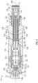
- FIG. 2 and Figure 3 present closer views of a transducer assembly 110 showing that piezoelectric capsule 115 includes an axially-extendable, elongate body 120 extending along central axis 111 from a first end 122 to a second end 123, an axially-extendable wireway 124 between ends 122, 123, a transformer 126 located within body 120 proximal second end 123, and an end cap 130 at second end 123.
- Transformer 126 is axially spaced from piezoelectric element 118.
- a plurality of conductors 128 extends through the extendable wireway 124 and electrically couples the element 118 with transformer 126. Conductors 128 have sufficient length to accommodate the adjustable length of wireway 124 and body 120.
- Conductors 128 may be, as examples, coiled, kinked, foldable, or bendable.
- a plurality of conductor pins 129 held in the end cap 130 are electrically coupled between transformer 126 and a removable cord set 134.
- End cap 130 includes axially-extending slots 131 in a sidewall that receive pins 132 extending radially inward from capsule body 120, and a resilient member 133 is captured between end cap 130 and body 120.
- capsule 115 is configured to extend and contract, allowing body 120 with pins 123 to move axially a prescribed distance (e.g., the axial length of slots 131) relative to cap 130.
- Resilient member 133 biases body 120 away from cap 130, or vice versa.
- piezoelectric capsule 115 With this mounting of cap 130 to body 120, piezoelectric capsule 115 is extendable to firmly but gently hold transformer 126 inside body 115 or to press piezoelectric element 118 toward or against the end of front cap 142.
- Resilient member 133 is, as examples, a coiled spring or a wave spring.
- outer housing 140 includes a tubular, front cap 142, a tubular body 144, and a cord retainer 146, and a multi-diameter bore 148 that extends through retainer 146, body 144, and cap 142.
- Body 144 extends from a first end 152 to a threaded second end 153 and includes annular flanges 154 located along its outer surface between ends 152, 153. In various embodiments, the axial location of flanges 154 between ends 152, 153 can be altered to compensate for the wall thickness of the flow meter that is to receive transducer assembly 110.
- Body 144 may also be called a stalk.
- piezoelectric capsule 115 is received within bore 148 and resides within retainer 146, body 144, and cap 142.
- Cord retainer 146 is threadingly received on second end 153, cord set 134 is held within retainer 146, and an end 143 of front cap 142 is sealed within the body's first end 152 and held by various retaining members 164 that include an isolation spring, an isolation washer, and a retaining ring.
- an interface disc 166 is located between piezoelectric element 118 and the inner surface of front cap 142 at front end 112.
- interface disc 166 is electrically insulating and is made from DuPont TM Kapton ® polyimide film. Some embodiments use another material while still others lack an interface disc 166.
- Body 120 includes a first member 180 installable and removable from second member 220.
- First member 180 comprises a head portion 182 extending from first end 122 to a leg portion 185, which extends to a second end 183 of first member 180.
- Leg portion 185 has an outer diameter less than the outer diameter of head portion 182 and includes a pair of legs 186 extending axially away from the head portion 182 and a slot 188 between the legs.
- Slot 188 extends through only a part of leg region 185, and the non-slotted part may be called a central region of first member 180.
- Each leg 186 includes a latch tab 190 extending radially proximal the end 183.
- FIG. 5 shows a closer view of a latch tab 190 adjacent the end 183 on a leg 186.
- Latch tab 190 includes radially extending front & rear surfaces 192 facing towards ends 183, 122, and first and second side surfaces 194, which are configured as camming surfaces, smoothly extending in the circumferential and radial directions from the outer surface of leg 186 to a top surface 196. Fillets are included to form smooth transitions from one surface to another at camming surfaces 194.
- Top surface 196 is curved, following a circular path.
- Front & rear surfaces 192 are substantially perpendicular to axis 111.
- leg portion 185 of first member 180 includes a tubular wall divided lengthwise by slot 188, which is tapered, being wider at end 183.
- a multi-diameter throughbore 189 extends entirely through leg portion 185 and head portion 182.
- Piezoelectric element 118 is disposed in or adjacent throughbore 189 at first end 122.
- Figure 6 and 7 show another exemplary embodiment, a first member 180B that includes the same features as member 180 in Figure 4 and Figure 5 ; however, a straight slot 188B replaces the tapered slot 188.
- the sidewalls of slot 188B are straight as they extend axially from a mid-location along leg portion 185 through the end 183.
- Member 180B includes a radially-extending aperture 202 and an external slot 204 in head portion 182 to provide a path for a conductor 128 to reach the front, exterior surface of a piezoelectric element 118 ( Figure 4 ).
- first and second camming surfaces 194 on latch tabs 190 include flat portions that are oriented at an angle 198 from each other.
- angle 198 has a value of substantially 60 degrees. Other embodiments may use an angle 198 that is greater or less than 60 degrees. Some embodiments use another shape for camming surfaces 194; for example, some camming surfaces are entirely curved, lacking flat portions. The outer diameter 206 of top surface 196 is less that the outer diameter 208 of head portion 182. First member 180B is interchangeable with first member 180 within a piezoelectric capsule 115.
- second member 220 extends from a sleeve 225 at a first end 222 to a body portion 240 at a second end 223.
- Sleeve 225 includes an elongate receiving chamber 228 defined by a chamber wall 230 extending along a sleeve axis 232.
- Sleeve 225 includes a plurality of axially-spaced apertures 234, which may also be called latch slots.
- an aperture 234 is rectangular and includes circumferentially-spaced sides 235 intersecting the wall of chamber 228.
- apertures 234 are grouped as pairs of two apertures 234 located at a same axial position along axis 232 and circumferentially spaced-apart.
- the rows 236 are circumferentially spaced about the sleeve axis 232, being located 180 degrees apart in this embodiment.
- Eight pairs of aligned apertures 234 are shown, but other embodiments may have more or fewer than eight pairs of apertures 234.
- body portion 240 of second member 220 is tubular and includes a multi-diameter bore 242 extending from second end 223, an internal wall 244 at the intersection of body portion 240 and sleeve 225, and a plurality of through bores 246 extending axially through the wall 244 to provide passages for conductors 128.
- wireway 124 includes receiving chamber 228 of second member 220 and slot 188 of first member 180.
- Wireway 124 also includes bore 242 and bores 246 of second member 220 and throughbore 189 of first member 180, which intersects slot 188.
- Chamber 228 is configured to receive legs 186, and each aperture 234 is configured to capture a latch tab 190, to latch the location of first member 180 relative to second member 220 at various axial positions, to achieve various lengths for capsule body 120.
- each pair of aligned apertures 234 is configured to capture concurrently the two latch tabs 190 on the two legs 186, as shown in the example of Figure 2 .
- the operation of capsule 115 includes aligning sleeve axis 232 with axis 111 and first member 180.
- Legs 186 are configured to be flexed radially inward toward the sleeve axis 232 while the legs 186 are moved in a direction toward body portion 240 and transformer 126 in order to install legs 186 inside chamber 228.
- Legs 186 can be move axially until latch tabs 190 are captured within a pair of apertures 234.
- Legs 186 are configured such that first member 180 cannot move axially with respect to the second member 220 when the latch tabs 190 are captured in any of the apertures 234 of rows 236.
- Legs 186 are also configured such that the first member 180 can rotate about the sleeve axis 232 within sleeve 225 when latch tabs 190 are captured in any pair of apertures 234 and also when the latch tab is not captured in an aperture 234.
- latch tabs 190 are captured in a pair of apertures 234, and legs 186 are rotated about sleeve axis 232 relative to second member 220, tabs 190 are biased out of engagement with apertures 234 that held them.
- tabs 190 may be removed or released from apertures 234 without a radial force being exerted on top surface 196.
- tabs 190 may be released without an assembler pressing surface 196 radially inward before or during rotation of member 180 relative to member 220. This configuration may be described as "rotate-to-release.”
- first member 180 When released or not engaged, first member 180 may be moved axially with respect to second member 220 while tabs 190 are disengaged from the rows of apertures 234.
- first member 180 may be rotated by 45 degree, 90 degrees, or 135 degrees, or by another suitable angle to disengage latch tabs 190 from any pair of apertures 234.
- Figure 9 demonstrates the shortest length of piezoelectric capsule 115 of this embodiment, with latch tabs 190 captured within the pair of apertures 234A proximal second end 123 and distal the first end 122.
- Figure 9 corresponds to the configuration of capsule 115 shown in Figure 2 .
- Figure 10 demonstrates the longest length of capsule 115, with latch tabs 190 captured within the pair of apertures 234B proximal the first end 122. In this position, a majority of the length of each leg 186 is outside of sleeve 225.
- First member 180 may be extended and retracted with respect to second member 220 such that latch tabs 190 are captured in any of the pairs apertures 234 represented in Figure 9 and figure 10 .
- the distance 252 between apertures 234A and apertures 234B is 67% of the length 254 of sleeve 225. In some embodiments, distance 252 is selected from a value in the range 10% to 67% of the length 254 of sleeve 225. In some embodiments distance 252 is greater than 60% of the length 254. In some other embodiments, distance 252 is less than 20% of the length 254, and some of these embodiments with shorter distances 252 have fewer than eight pairs of apertures 234.
- the length of capsule 115 that is selected and set for use in a given flow meter will be based in part on the wall thickness 108 of the flow meter and the angular orientation of ports 106 relative to flow meter axis 105, which influence the length of port 106.
- the outer housing 140 may be different from the example shown in Figure 1A and Figure 2 .
- the axial location of flanges 154 along body 144 may be different to change what length portion of capsule 115 extends within port 106, and what remaining portion of capsule 115 remains outside port 106 or spool piece 102. Therefore, piezoelectric capsule 115 is a transducer assembly that is configured to fit within flow meters of various sizes and wall thicknesses.
- the side surfaces of latch tabs do not perform effectively as camming surfaces when an assembler attempts to rotate a first member relative to a second member while a latch tab is held within a slot on a second member.
- the side surfaces 194 of latch tabs 190 may be steeper that described above, having an angle 198 ( Figure 6 ) less than 10 degrees, as an example.
- Such embodiments are configured to change length when a user presses inward on latch tabs 190 to release them from slots 234 before the first member is moved axially or rotated with respect to the second member 220. This configuration may be described as "press-to-release.”
- first members 180, 180B were described as each having a pair of latch tabs 190, and second member 220 was described as having first and second rows 236 of apertures 234, in some embodiments of piezoelectric capsule 115, a first member has only one latch tab 190, and a second member has a single row 236 of apertures 234. Such combinations of first and second members may also be configured as rotate-to-release or as press-to-release.
Claims (14)
- Ensemble transducteur (110) comprenant :un boîtier de transducteur (140) ;une capsule piézoélectrique (115) scellée à l'intérieur du boîtier de transducteur, la capsule piézoélectrique (115) comprenant :un corps allongé (120) ayant une longueur réglable et de première et seconde extrémités opposées (122, 123), dans lequel le corps allongé (120) est extensible et rétractable entre diverses longueurs, et dans lequel le corps allongé est verrouillable dans une longueur donnée des diverses longueurs ;un élément piézoélectrique (118) disposé dans le corps allongé (120) adjacent à la première extrémité (122) ;un transformateur (126) ;un chemin de câbles extensible axialement (124), positionné à l'intérieur du corps allongé (120) ; etcaractérisé en ce que la capsule piézoélectrique comprend en outre :un conducteur (128) couplé électriquement à l'élément piézoélectrique (118) et au transformateur et s'étendant à travers le chemin de câbles extensible (124),dans lequel l'élément piézoélectrique (118) et le transformateur (126) sont positionnés de manière adjacente aux extrémités opposées (122, 123) du corps allongé (120).
- Ensemble transducteur selon la revendication 1, le corps allongé (120) comprenant :un premier élément (180) comprenant une partie de tête (182), une paire de pattes (186) s'étendant axialement à l'écart de la partie de tête (182) et une fente entre les pattes, au moins une patte comprenant une languette de verrouillage (190) s'étendant à partir de celle-ci ; etun second élément (220) comprenant un manchon (225) ayant une chambre de réception allongée définie par une paroi de chambre et configurée pour recevoir les pattes (186) à l'intérieur, le manchon comprenant une pluralité d'ouvertures (234), la paroi de chambre étant configurée pour capturer la languette de verrouillage (190) ;dans lequel l'élément piézoélectrique est monté sur le premier élément (180) et dans lequel le chemin de câbles extensible (124) comprend la chambre de réception et la fente.
- Ensemble transducteur selon la revendication 2, dans lequel la pluralité d'ouvertures (234) comprend au moins une rangée d'ouvertures alignées (234) dans la paroi de chambre, dans lequel chacune des ouvertures est configurée pour capturer la languette de verrouillage.
- Ensemble transducteur selon la revendication 2, dans lequel le manchon comprend un axe de manchon et dans lequel les extrémités des pattes (186) sont configurées pour fléchir radialement vers l'intérieur en direction de l'axe de manchon lorsque les pattes sont déplacées dans la chambre de réception et avant que la languette de verrouillage ne soit capturée dans une ouverture (234) ; ou
dans lequel la languette de verrouillage inclut une surface de came ; et dans lequel la languette de verrouillage est configurée de telle sorte que la rotation du premier élément par rapport au second élément sollicite la languette hors de l'engagement avec l'une de la pluralité d'ouvertures (234) . - Ensemble transducteur selon la revendication 3, dans lequel le manchon comprend un axe de manchon, et dans lequel les pattes sont configurées de telle sorte que, lorsque la languette de verrouillage est capturée dans une première ouverture de la rangée et que les pattes sont tournées autour de l'axe de manchon, la languette est sollicitée hors de l'engagement avec la première ouverture ; ou
dans lequel le manchon comprend un axe de manchon ; et dans lequel les pattes sont configurées de telle sorte que le premier élément ne peut pas se déplacer axialement par rapport au second élément lorsque la languette de verrouillage est capturée dans une première ouverture de la rangée ; et dans lequel les pattes sont configurées de telle sorte que le premier élément peut tourner autour de l'axe de manchon à l'intérieur du manchon lorsque la languette de verrouillage est capturée dans la première ouverture et également lorsque la languette de verrouillage n'est pas capturée dans la première ouverture. - Ensemble transducteur selon la revendication 3, dans lequel le manchon comprend un axe de manchon et dans lequel chaque patte comprend une languette de verrouillage ; et
dans lequel le manchon comprend une pluralité de paires d'ouvertures espacées axialement, les paires définissant deux rangées d'ouvertures alignées, chaque ouverture étant configurée pour capturer une languette de verrouillage, et les rangées étant espacées de 180 degrés autour de l'axe de manchon. - Ensemble transducteur selon la revendication 6, dans lequel les pattes sont configurées de telle sorte que, lorsque la languette de verrouillage de chaque patte est capturée dans l'une des ouvertures d'une paire d'ouvertures et que le premier élément est tourné autour de l'axe de manchon, la languette de chaque patte est sollicitée hors de l'engagement avec une ouverture.
- Ensemble transducteur selon la revendication 1, le corps allongé comprenant :un premier élément comprenant une partie de tête au niveau de la première extrémité, une patte s'étendant axialement à l'écart de la partie de tête, une languette de verrouillage s'étendant radialement à partir d'une extrémité de la patte distale de la partie de tête ;un second élément s'étendant à partir de la seconde extrémité vers la première extrémité et comprenant un manchon ayant une chambre de réception allongée définie par une paroi de chambre et configurée pour recevoir la patte à l'intérieur, le manchon comprenant de première et seconde ouvertures espacées axialement dans la paroi de chambre, chaque ouverture étant configurée pour capturer la languette de verrouillage de sorte que la longueur du corps allongé entre les première et seconde extrémités est réglable ;le chemin de câbles extensible axialement est situé dans le premier élément et le second élément.
- Ensemble transducteur selon la revendication 8, dans lequel le manchon comprend un axe de manchon ;dans lequel la patte inclut une surface extérieure ;dans lequel la languette de verrouillage inclut une surface supérieure et une surface de came, la surface de came s'étendant dans les directions circonférentielle et radiale depuis la surface extérieure de la patte jusqu'à la surface supérieure de la languette de verrouillage ;dans lequel la surface de came est configurée pour se déplacer sur un côté de la première ou de la seconde ouverture lorsque le premier élément est tourné autour de l'axe de manchon par rapport au second élément pour amener l'extrémité de la patte à fléchir radialement vers l'intérieur vers l'axe de manchon, sollicitant ainsi la languette hors de l'engagement avec la première ou la seconde ouverture.
- Débitmètre à ultrasons (100) pour mesurer l'écoulement d'un fluide, comprenant :un corps de compteur (102) incluant un alésage traversant (104) et un orifice de transducteur (106) s'étendant depuis une surface extérieure du corps de compteur jusqu'à l'alésage traversant ; etun ensemble transducteur (110) selon l'une quelconque des revendications précédentes disposé dans l'orifice de transducteur (106).
- Débitmètre selon la revendication 10, dans lequel le corps allongé (120) comprend en outre :un premier élément comprenant une partie de tête et une paire de pattes s'étendant axialement à l'écart de la partie de tête, au moins une patte comprenant une languette de verrouillage s'étendant à partir de celle-ci ; etun second élément comprenant un manchon ayant une chambre de réception allongée définie par une paroi de chambre et configurée pour recevoir les pattes à l'intérieur, le manchon comprenant une pluralité d'ouvertures (234), la paroi de chambre étant configurée pour capturer la languette de verrouillage.
- Débitmètre selon la revendication 11, dans lequel la pluralité d'ouvertures (234) comprend au moins une rangée d'ouvertures alignées dans la paroi de chambre, dans lequel chacune des ouvertures est configurée pour capturer la languette de verrouillage.
- Débitmètre selon la revendication 11, dans lequel le manchon comprend un axe de manchon et dans lequel les extrémités des pattes sont configurées pour fléchir radialement vers l'intérieur vers l'axe de manchon lorsque les pattes sont déplacées dans une direction vers le transformateur et avant que la languette de verrouillage ne soit capturée dans l'une de la pluralité d'ouvertures (234).
- Débitmètre selon la revendication 11, dans lequel la languette de verrouillage comprend une surface de came ; et
dans lequel la languette de verrouillage est configurée de telle sorte que la rotation du premier élément par rapport au second élément sollicite la languette hors de l'engagement avec l'une de la pluralité d'ouvertures (234).
Applications Claiming Priority (2)
| Application Number | Priority Date | Filing Date | Title |
|---|---|---|---|
| US201762578376P | 2017-10-27 | 2017-10-27 | |
| PCT/US2018/052500 WO2019083662A1 (fr) | 2017-10-27 | 2018-09-24 | Ensembles transducteurs réglables |
Publications (3)
| Publication Number | Publication Date |
|---|---|
| EP3701229A1 EP3701229A1 (fr) | 2020-09-02 |
| EP3701229A4 EP3701229A4 (fr) | 2021-08-11 |
| EP3701229B1 true EP3701229B1 (fr) | 2023-03-15 |
Family
ID=66242822
Family Applications (1)
| Application Number | Title | Priority Date | Filing Date |
|---|---|---|---|
| EP18871358.0A Active EP3701229B1 (fr) | 2017-10-27 | 2018-09-24 | Ensembles transducteurs réglables |
Country Status (5)
| Country | Link |
|---|---|
| US (1) | US10718645B2 (fr) |
| EP (1) | EP3701229B1 (fr) |
| CN (2) | CN109724656B (fr) |
| CA (1) | CA3084420C (fr) |
| WO (1) | WO2019083662A1 (fr) |
Families Citing this family (3)
| Publication number | Priority date | Publication date | Assignee | Title |
|---|---|---|---|---|
| CN206440316U (zh) * | 2017-01-23 | 2017-08-25 | 青岛海威茨仪表有限公司 | 一种多通道超声波流量计 |
| US10718645B2 (en) * | 2017-10-27 | 2020-07-21 | Daniel Measurement And Control, Inc. | Adjustable transducer assemblies |
| EP4021650A4 (fr) * | 2019-08-28 | 2023-09-06 | SCR Engineers Ltd | Dispositifs d'analyse d'un fluide |
Citations (4)
| Publication number | Priority date | Publication date | Assignee | Title |
|---|---|---|---|---|
| US5437194A (en) * | 1991-03-18 | 1995-08-01 | Panametrics, Inc. | Ultrasonic transducer system with temporal crosstalk isolation |
| DE102013109349A1 (de) * | 2013-08-29 | 2015-03-05 | Endress + Hauser Flowtec Ag | Ultraschallwandler und Ultraschall-Durchflussmessgerät |
| EP2418464B1 (fr) * | 2005-08-12 | 2017-06-21 | Daniel Measurement and Control, Inc. | Méthode pour remplacer un assemblage d'un transducteur pour compteur de fluide ultrasonique |
| EP2382447B1 (fr) * | 2010-03-01 | 2019-11-20 | Cla-Val Company | Débitmètre de fluide |
Family Cites Families (18)
| Publication number | Priority date | Publication date | Assignee | Title |
|---|---|---|---|---|
| US3890423A (en) * | 1973-07-27 | 1975-06-17 | Nusonics | Electroacoustic transducer assembly |
| US4596133A (en) * | 1983-07-29 | 1986-06-24 | Panametrics, Inc. | Apparatus and methods for measuring fluid flow parameters |
| US5484416A (en) * | 1993-08-05 | 1996-01-16 | Advanced Cardiovascular Systems, Inc. | Coaxial cable vascular access system for use in various needles |
| US5780747A (en) * | 1995-12-18 | 1998-07-14 | Changmin Co., Ltd. | Open channel multichannel ultrasonic flowrate measurement apparatus and method |
| CN1346047A (zh) * | 2000-09-22 | 2002-04-24 | 克洛纳测量技术公司 | 超声换能器 |
| US7397168B2 (en) | 2005-08-12 | 2008-07-08 | Daniel Measurement And Control, Inc. | Transducer housing for an ultrasonic fluid meter |
| CN100587988C (zh) | 2005-08-12 | 2010-02-03 | 丹尼尔度量和控制公司 | 用于超声流量计的换能器组件 |
| MX2011010805A (es) * | 2009-04-13 | 2012-01-25 | Daniel Measurement & Control | Transductor que tiene una conexion electrica robusta a un crystal piezoelectrico. |
| US7966893B2 (en) * | 2009-06-16 | 2011-06-28 | Daniel Measurement And Control, Inc. | Adjusting transducer frequency without ceasing fluid flow through a meter |
| US8132469B2 (en) * | 2010-01-06 | 2012-03-13 | Daniel Measurement And Control, Inc. | Ultrasonic flow meter with transducer assembly having a rotatable receptacle and elbow connector |
| US8181533B2 (en) * | 2010-01-06 | 2012-05-22 | Daniel Measurement And Control, Inc. | Ultrasonic flow meter and transducer assembly with isolated transformer capsule |
| US8186229B2 (en) | 2010-01-06 | 2012-05-29 | Daniel Measurement And Control, Inc. | Ultrasonic flow meter having a port cover assembly |
| WO2012097005A1 (fr) * | 2011-01-10 | 2012-07-19 | Benjamin Pietro Filardo | Mécanismes pour créer un mouvement ondulatoire, par exemple pour la propulsion, et pour exploiter l'énergie d'un fluide en mouvement |
| CN102708851B (zh) * | 2012-06-25 | 2014-01-08 | 唐山海通电子有限公司 | 收发型水声换能器 |
| WO2016012024A1 (fr) * | 2014-07-21 | 2016-01-28 | Apator Miitors Aps | Accessoire intérieur de conduit pour un débitmètre ultrasonore |
| US20160070016A1 (en) * | 2014-09-08 | 2016-03-10 | Baker Hughes Incorporated | Downhole sensor, ultrasonic level sensing assembly, and method |
| US10240711B2 (en) * | 2016-09-19 | 2019-03-26 | Inducomp Corporation | Security support stand for mounted tablet type computer |
| US10718645B2 (en) * | 2017-10-27 | 2020-07-21 | Daniel Measurement And Control, Inc. | Adjustable transducer assemblies |
-
2018
- 2018-09-24 US US16/140,504 patent/US10718645B2/en active Active
- 2018-09-24 WO PCT/US2018/052500 patent/WO2019083662A1/fr unknown
- 2018-09-24 CA CA3084420A patent/CA3084420C/fr active Active
- 2018-09-24 EP EP18871358.0A patent/EP3701229B1/fr active Active
- 2018-10-25 CN CN201811249822.8A patent/CN109724656B/zh active Active
- 2018-10-25 CN CN201821743883.5U patent/CN209589143U/zh not_active Withdrawn - After Issue
Patent Citations (4)
| Publication number | Priority date | Publication date | Assignee | Title |
|---|---|---|---|---|
| US5437194A (en) * | 1991-03-18 | 1995-08-01 | Panametrics, Inc. | Ultrasonic transducer system with temporal crosstalk isolation |
| EP2418464B1 (fr) * | 2005-08-12 | 2017-06-21 | Daniel Measurement and Control, Inc. | Méthode pour remplacer un assemblage d'un transducteur pour compteur de fluide ultrasonique |
| EP2382447B1 (fr) * | 2010-03-01 | 2019-11-20 | Cla-Val Company | Débitmètre de fluide |
| DE102013109349A1 (de) * | 2013-08-29 | 2015-03-05 | Endress + Hauser Flowtec Ag | Ultraschallwandler und Ultraschall-Durchflussmessgerät |
Also Published As
| Publication number | Publication date |
|---|---|
| CN109724656A (zh) | 2019-05-07 |
| CN109724656B (zh) | 2021-06-29 |
| CN209589143U (zh) | 2019-11-05 |
| EP3701229A4 (fr) | 2021-08-11 |
| CA3084420A1 (fr) | 2019-05-02 |
| CA3084420C (fr) | 2024-02-13 |
| EP3701229A1 (fr) | 2020-09-02 |
| US10718645B2 (en) | 2020-07-21 |
| WO2019083662A1 (fr) | 2019-05-02 |
| US20190128714A1 (en) | 2019-05-02 |
Similar Documents
| Publication | Publication Date | Title |
|---|---|---|
| EP3701229B1 (fr) | Ensembles transducteurs réglables | |
| US20110162460A1 (en) | Ultrasonic Flow Meter And Transducer Assembly With Isolated Transformer Capsule | |
| US20110162462A1 (en) | Ultrasonic Flow Meter With Transducer Assembly Having a Rotatable Receptacle and Elbow Connector | |
| US9297680B2 (en) | Ultrasonic flow meter having deterioration suppression in flow rate accuracy | |
| US20110162463A1 (en) | Ultrasonic Flow Meter Having A Port Cover Assembly | |
| CA2899764C (fr) | Procede et systeme d'ensemble transducteur de debitmetre a ultrasons | |
| CA2994149C (fr) | Debitmetre comportant un ensemble enceinte pour circuits electroniques | |
| MX2012007921A (es) | Medidor de flujo ultrasónico, ensamble de transductor y métodos de fabricación de los mismos. | |
| US20180087935A1 (en) | Position Sensor | |
| GB2604567A8 (en) | Magnetic freepoint indicator tool | |
| JP2009250733A (ja) | 計測モジュール | |
| US10048149B2 (en) | Relative pressure sensor | |
| CN109489749B (zh) | 流量计和用于制造流量计的方法 | |
| KR101007144B1 (ko) | 초음파 유량계용 트랜스듀서의 고정공구 | |
| US11128067B2 (en) | Electrical connector with adjustable alignment member | |
| TWM610430U (zh) | 接合結構 | |
| WO2011113166A3 (fr) | Capteur présentant un dispositif de serrage évitant la déformation |
Legal Events
| Date | Code | Title | Description |
|---|---|---|---|
| STAA | Information on the status of an ep patent application or granted ep patent |
Free format text: STATUS: THE INTERNATIONAL PUBLICATION HAS BEEN MADE |
|
| PUAI | Public reference made under article 153(3) epc to a published international application that has entered the european phase |
Free format text: ORIGINAL CODE: 0009012 |
|
| STAA | Information on the status of an ep patent application or granted ep patent |
Free format text: STATUS: REQUEST FOR EXAMINATION WAS MADE |
|
| 17P | Request for examination filed |
Effective date: 20200526 |
|
| AK | Designated contracting states |
Kind code of ref document: A1 Designated state(s): AL AT BE BG CH CY CZ DE DK EE ES FI FR GB GR HR HU IE IS IT LI LT LU LV MC MK MT NL NO PL PT RO RS SE SI SK SM TR |
|
| AX | Request for extension of the european patent |
Extension state: BA ME |
|
| DAV | Request for validation of the european patent (deleted) | ||
| DAX | Request for extension of the european patent (deleted) | ||
| A4 | Supplementary search report drawn up and despatched |
Effective date: 20210708 |
|
| RIC1 | Information provided on ipc code assigned before grant |
Ipc: G01F 1/66 20060101AFI20210702BHEP Ipc: G01F 15/14 20060101ALI20210702BHEP Ipc: G01F 15/18 20060101ALI20210702BHEP Ipc: B06B 1/02 20060101ALI20210702BHEP Ipc: B06B 1/06 20060101ALI20210702BHEP |
|
| RAP1 | Party data changed (applicant data changed or rights of an application transferred) |
Owner name: MICRO MOTION, INC. |
|
| GRAP | Despatch of communication of intention to grant a patent |
Free format text: ORIGINAL CODE: EPIDOSNIGR1 |
|
| STAA | Information on the status of an ep patent application or granted ep patent |
Free format text: STATUS: GRANT OF PATENT IS INTENDED |
|
| INTG | Intention to grant announced |
Effective date: 20221011 |
|
| GRAS | Grant fee paid |
Free format text: ORIGINAL CODE: EPIDOSNIGR3 |
|
| GRAA | (expected) grant |
Free format text: ORIGINAL CODE: 0009210 |
|
| STAA | Information on the status of an ep patent application or granted ep patent |
Free format text: STATUS: THE PATENT HAS BEEN GRANTED |
|
| AK | Designated contracting states |
Kind code of ref document: B1 Designated state(s): AL AT BE BG CH CY CZ DE DK EE ES FI FR GB GR HR HU IE IS IT LI LT LU LV MC MK MT NL NO PL PT RO RS SE SI SK SM TR |
|
| REG | Reference to a national code |
Ref country code: CH Ref legal event code: EP Ref country code: GB Ref legal event code: FG4D |
|
| REG | Reference to a national code |
Ref country code: DE Ref legal event code: R096 Ref document number: 602018047337 Country of ref document: DE |
|
| REG | Reference to a national code |
Ref country code: IE Ref legal event code: FG4D |
|
| REG | Reference to a national code |
Ref country code: AT Ref legal event code: REF Ref document number: 1554251 Country of ref document: AT Kind code of ref document: T Effective date: 20230415 |
|
| REG | Reference to a national code |
Ref country code: NL Ref legal event code: FP |
|
| REG | Reference to a national code |
Ref country code: LT Ref legal event code: MG9D |
|
| P01 | Opt-out of the competence of the unified patent court (upc) registered |
Effective date: 20230530 |
|
| PG25 | Lapsed in a contracting state [announced via postgrant information from national office to epo] |
Ref country code: RS Free format text: LAPSE BECAUSE OF FAILURE TO SUBMIT A TRANSLATION OF THE DESCRIPTION OR TO PAY THE FEE WITHIN THE PRESCRIBED TIME-LIMIT Effective date: 20230315 Ref country code: NO Free format text: LAPSE BECAUSE OF FAILURE TO SUBMIT A TRANSLATION OF THE DESCRIPTION OR TO PAY THE FEE WITHIN THE PRESCRIBED TIME-LIMIT Effective date: 20230615 Ref country code: LV Free format text: LAPSE BECAUSE OF FAILURE TO SUBMIT A TRANSLATION OF THE DESCRIPTION OR TO PAY THE FEE WITHIN THE PRESCRIBED TIME-LIMIT Effective date: 20230315 Ref country code: LT Free format text: LAPSE BECAUSE OF FAILURE TO SUBMIT A TRANSLATION OF THE DESCRIPTION OR TO PAY THE FEE WITHIN THE PRESCRIBED TIME-LIMIT Effective date: 20230315 Ref country code: HR Free format text: LAPSE BECAUSE OF FAILURE TO SUBMIT A TRANSLATION OF THE DESCRIPTION OR TO PAY THE FEE WITHIN THE PRESCRIBED TIME-LIMIT Effective date: 20230315 |
|
| REG | Reference to a national code |
Ref country code: AT Ref legal event code: MK05 Ref document number: 1554251 Country of ref document: AT Kind code of ref document: T Effective date: 20230315 |
|
| PG25 | Lapsed in a contracting state [announced via postgrant information from national office to epo] |
Ref country code: SE Free format text: LAPSE BECAUSE OF FAILURE TO SUBMIT A TRANSLATION OF THE DESCRIPTION OR TO PAY THE FEE WITHIN THE PRESCRIBED TIME-LIMIT Effective date: 20230315 Ref country code: GR Free format text: LAPSE BECAUSE OF FAILURE TO SUBMIT A TRANSLATION OF THE DESCRIPTION OR TO PAY THE FEE WITHIN THE PRESCRIBED TIME-LIMIT Effective date: 20230616 Ref country code: FI Free format text: LAPSE BECAUSE OF FAILURE TO SUBMIT A TRANSLATION OF THE DESCRIPTION OR TO PAY THE FEE WITHIN THE PRESCRIBED TIME-LIMIT Effective date: 20230315 |
|
| PGFP | Annual fee paid to national office [announced via postgrant information from national office to epo] |
Ref country code: NL Payment date: 20230822 Year of fee payment: 6 |
|
| PG25 | Lapsed in a contracting state [announced via postgrant information from national office to epo] |
Ref country code: SM Free format text: LAPSE BECAUSE OF FAILURE TO SUBMIT A TRANSLATION OF THE DESCRIPTION OR TO PAY THE FEE WITHIN THE PRESCRIBED TIME-LIMIT Effective date: 20230315 Ref country code: RO Free format text: LAPSE BECAUSE OF FAILURE TO SUBMIT A TRANSLATION OF THE DESCRIPTION OR TO PAY THE FEE WITHIN THE PRESCRIBED TIME-LIMIT Effective date: 20230315 Ref country code: PT Free format text: LAPSE BECAUSE OF FAILURE TO SUBMIT A TRANSLATION OF THE DESCRIPTION OR TO PAY THE FEE WITHIN THE PRESCRIBED TIME-LIMIT Effective date: 20230717 Ref country code: ES Free format text: LAPSE BECAUSE OF FAILURE TO SUBMIT A TRANSLATION OF THE DESCRIPTION OR TO PAY THE FEE WITHIN THE PRESCRIBED TIME-LIMIT Effective date: 20230315 Ref country code: EE Free format text: LAPSE BECAUSE OF FAILURE TO SUBMIT A TRANSLATION OF THE DESCRIPTION OR TO PAY THE FEE WITHIN THE PRESCRIBED TIME-LIMIT Effective date: 20230315 Ref country code: CZ Free format text: LAPSE BECAUSE OF FAILURE TO SUBMIT A TRANSLATION OF THE DESCRIPTION OR TO PAY THE FEE WITHIN THE PRESCRIBED TIME-LIMIT Effective date: 20230315 Ref country code: AT Free format text: LAPSE BECAUSE OF FAILURE TO SUBMIT A TRANSLATION OF THE DESCRIPTION OR TO PAY THE FEE WITHIN THE PRESCRIBED TIME-LIMIT Effective date: 20230315 |
|
| PGFP | Annual fee paid to national office [announced via postgrant information from national office to epo] |
Ref country code: IT Payment date: 20230822 Year of fee payment: 6 Ref country code: GB Payment date: 20230822 Year of fee payment: 6 |
|
| PG25 | Lapsed in a contracting state [announced via postgrant information from national office to epo] |
Ref country code: SK Free format text: LAPSE BECAUSE OF FAILURE TO SUBMIT A TRANSLATION OF THE DESCRIPTION OR TO PAY THE FEE WITHIN THE PRESCRIBED TIME-LIMIT Effective date: 20230315 Ref country code: PL Free format text: LAPSE BECAUSE OF FAILURE TO SUBMIT A TRANSLATION OF THE DESCRIPTION OR TO PAY THE FEE WITHIN THE PRESCRIBED TIME-LIMIT Effective date: 20230315 Ref country code: IS Free format text: LAPSE BECAUSE OF FAILURE TO SUBMIT A TRANSLATION OF THE DESCRIPTION OR TO PAY THE FEE WITHIN THE PRESCRIBED TIME-LIMIT Effective date: 20230715 |
|
| PGFP | Annual fee paid to national office [announced via postgrant information from national office to epo] |
Ref country code: FR Payment date: 20230822 Year of fee payment: 6 Ref country code: DE Payment date: 20230822 Year of fee payment: 6 |
|
| REG | Reference to a national code |
Ref country code: DE Ref legal event code: R097 Ref document number: 602018047337 Country of ref document: DE |
|
| PLBE | No opposition filed within time limit |
Free format text: ORIGINAL CODE: 0009261 |
|
| STAA | Information on the status of an ep patent application or granted ep patent |
Free format text: STATUS: NO OPPOSITION FILED WITHIN TIME LIMIT |
|
| PG25 | Lapsed in a contracting state [announced via postgrant information from national office to epo] |
Ref country code: SI Free format text: LAPSE BECAUSE OF FAILURE TO SUBMIT A TRANSLATION OF THE DESCRIPTION OR TO PAY THE FEE WITHIN THE PRESCRIBED TIME-LIMIT Effective date: 20230315 Ref country code: DK Free format text: LAPSE BECAUSE OF FAILURE TO SUBMIT A TRANSLATION OF THE DESCRIPTION OR TO PAY THE FEE WITHIN THE PRESCRIBED TIME-LIMIT Effective date: 20230315 |
|
| PGFP | Annual fee paid to national office [announced via postgrant information from national office to epo] |
Ref country code: CH Payment date: 20231001 Year of fee payment: 6 |
|
| 26N | No opposition filed |
Effective date: 20231218 |