EP3701190B1 - Beleuchtungsvorrichtung mit ultravioletter und blau-ultravioletter lichtquelle - Google Patents
Beleuchtungsvorrichtung mit ultravioletter und blau-ultravioletter lichtquelle Download PDFInfo
- Publication number
- EP3701190B1 EP3701190B1 EP18870125.4A EP18870125A EP3701190B1 EP 3701190 B1 EP3701190 B1 EP 3701190B1 EP 18870125 A EP18870125 A EP 18870125A EP 3701190 B1 EP3701190 B1 EP 3701190B1
- Authority
- EP
- European Patent Office
- Prior art keywords
- illuminator
- ultraviolet radiation
- ultraviolet
- radiation sources
- radiation
- Prior art date
- Legal status (The legal status is an assumption and is not a legal conclusion. Google has not performed a legal analysis and makes no representation as to the accuracy of the status listed.)
- Active
Links
Images

Classifications
-
- A—HUMAN NECESSITIES
- A61—MEDICAL OR VETERINARY SCIENCE; HYGIENE
- A61L—METHODS OR APPARATUS FOR STERILISING MATERIALS OR OBJECTS IN GENERAL; DISINFECTION, STERILISATION OR DEODORISATION OF AIR; CHEMICAL ASPECTS OF BANDAGES, DRESSINGS, ABSORBENT PADS OR SURGICAL ARTICLES; MATERIALS FOR BANDAGES, DRESSINGS, ABSORBENT PADS OR SURGICAL ARTICLES
- A61L2/00—Methods or apparatus for disinfecting or sterilising materials or objects other than foodstuffs or contact lenses; Accessories therefor
- A61L2/24—Apparatus using programmed or automatic operation
-
- A—HUMAN NECESSITIES
- A61—MEDICAL OR VETERINARY SCIENCE; HYGIENE
- A61L—METHODS OR APPARATUS FOR STERILISING MATERIALS OR OBJECTS IN GENERAL; DISINFECTION, STERILISATION OR DEODORISATION OF AIR; CHEMICAL ASPECTS OF BANDAGES, DRESSINGS, ABSORBENT PADS OR SURGICAL ARTICLES; MATERIALS FOR BANDAGES, DRESSINGS, ABSORBENT PADS OR SURGICAL ARTICLES
- A61L2/00—Methods or apparatus for disinfecting or sterilising materials or objects other than foodstuffs or contact lenses; Accessories therefor
- A61L2/0005—Methods or apparatus for disinfecting or sterilising materials or objects other than foodstuffs or contact lenses; Accessories therefor for pharmaceuticals, biologicals or living parts
- A61L2/0011—Methods or apparatus for disinfecting or sterilising materials or objects other than foodstuffs or contact lenses; Accessories therefor for pharmaceuticals, biologicals or living parts using physical methods
- A61L2/0029—Radiation
- A61L2/0047—Ultraviolet radiation
-
- A—HUMAN NECESSITIES
- A61—MEDICAL OR VETERINARY SCIENCE; HYGIENE
- A61L—METHODS OR APPARATUS FOR STERILISING MATERIALS OR OBJECTS IN GENERAL; DISINFECTION, STERILISATION OR DEODORISATION OF AIR; CHEMICAL ASPECTS OF BANDAGES, DRESSINGS, ABSORBENT PADS OR SURGICAL ARTICLES; MATERIALS FOR BANDAGES, DRESSINGS, ABSORBENT PADS OR SURGICAL ARTICLES
- A61L2/00—Methods or apparatus for disinfecting or sterilising materials or objects other than foodstuffs or contact lenses; Accessories therefor
- A61L2/0005—Methods or apparatus for disinfecting or sterilising materials or objects other than foodstuffs or contact lenses; Accessories therefor for pharmaceuticals, biologicals or living parts
- A61L2/0011—Methods or apparatus for disinfecting or sterilising materials or objects other than foodstuffs or contact lenses; Accessories therefor for pharmaceuticals, biologicals or living parts using physical methods
- A61L2/0029—Radiation
- A61L2/0052—Visible light
-
- A—HUMAN NECESSITIES
- A61—MEDICAL OR VETERINARY SCIENCE; HYGIENE
- A61L—METHODS OR APPARATUS FOR STERILISING MATERIALS OR OBJECTS IN GENERAL; DISINFECTION, STERILISATION OR DEODORISATION OF AIR; CHEMICAL ASPECTS OF BANDAGES, DRESSINGS, ABSORBENT PADS OR SURGICAL ARTICLES; MATERIALS FOR BANDAGES, DRESSINGS, ABSORBENT PADS OR SURGICAL ARTICLES
- A61L2/00—Methods or apparatus for disinfecting or sterilising materials or objects other than foodstuffs or contact lenses; Accessories therefor
- A61L2/02—Methods or apparatus for disinfecting or sterilising materials or objects other than foodstuffs or contact lenses; Accessories therefor using physical phenomena
- A61L2/08—Radiation
- A61L2/084—Visible light
-
- A—HUMAN NECESSITIES
- A61—MEDICAL OR VETERINARY SCIENCE; HYGIENE
- A61L—METHODS OR APPARATUS FOR STERILISING MATERIALS OR OBJECTS IN GENERAL; DISINFECTION, STERILISATION OR DEODORISATION OF AIR; CHEMICAL ASPECTS OF BANDAGES, DRESSINGS, ABSORBENT PADS OR SURGICAL ARTICLES; MATERIALS FOR BANDAGES, DRESSINGS, ABSORBENT PADS OR SURGICAL ARTICLES
- A61L2/00—Methods or apparatus for disinfecting or sterilising materials or objects other than foodstuffs or contact lenses; Accessories therefor
- A61L2/02—Methods or apparatus for disinfecting or sterilising materials or objects other than foodstuffs or contact lenses; Accessories therefor using physical phenomena
- A61L2/08—Radiation
- A61L2/088—Radiation using a photocatalyst or photosensitiser
-
- A—HUMAN NECESSITIES
- A61—MEDICAL OR VETERINARY SCIENCE; HYGIENE
- A61L—METHODS OR APPARATUS FOR STERILISING MATERIALS OR OBJECTS IN GENERAL; DISINFECTION, STERILISATION OR DEODORISATION OF AIR; CHEMICAL ASPECTS OF BANDAGES, DRESSINGS, ABSORBENT PADS OR SURGICAL ARTICLES; MATERIALS FOR BANDAGES, DRESSINGS, ABSORBENT PADS OR SURGICAL ARTICLES
- A61L2/00—Methods or apparatus for disinfecting or sterilising materials or objects other than foodstuffs or contact lenses; Accessories therefor
- A61L2/02—Methods or apparatus for disinfecting or sterilising materials or objects other than foodstuffs or contact lenses; Accessories therefor using physical phenomena
- A61L2/08—Radiation
- A61L2/10—Ultraviolet radiation
-
- A—HUMAN NECESSITIES
- A61—MEDICAL OR VETERINARY SCIENCE; HYGIENE
- A61N—ELECTROTHERAPY; MAGNETOTHERAPY; RADIATION THERAPY; ULTRASOUND THERAPY
- A61N5/00—Radiation therapy
- A61N5/06—Radiation therapy using light
- A61N5/0613—Apparatus adapted for a specific treatment
- A61N5/0624—Apparatus adapted for a specific treatment for eliminating microbes, germs, bacteria on or in the body
-
- G—PHYSICS
- G01—MEASURING; TESTING
- G01N—INVESTIGATING OR ANALYSING MATERIALS BY DETERMINING THEIR CHEMICAL OR PHYSICAL PROPERTIES
- G01N21/00—Investigating or analysing materials by the use of optical means, i.e. using sub-millimetre waves, infrared, visible or ultraviolet light
- G01N21/62—Systems in which the material investigated is excited whereby it emits light or causes a change in wavelength of the incident light
- G01N21/63—Systems in which the material investigated is excited whereby it emits light or causes a change in wavelength of the incident light optically excited
- G01N21/64—Fluorescence; Phosphorescence
- G01N21/6447—Fluorescence; Phosphorescence by visual observation
-
- G—PHYSICS
- G01—MEASURING; TESTING
- G01N—INVESTIGATING OR ANALYSING MATERIALS BY DETERMINING THEIR CHEMICAL OR PHYSICAL PROPERTIES
- G01N21/00—Investigating or analysing materials by the use of optical means, i.e. using sub-millimetre waves, infrared, visible or ultraviolet light
- G01N21/62—Systems in which the material investigated is excited whereby it emits light or causes a change in wavelength of the incident light
- G01N21/63—Systems in which the material investigated is excited whereby it emits light or causes a change in wavelength of the incident light optically excited
- G01N21/64—Fluorescence; Phosphorescence
- G01N21/645—Specially adapted constructive features of fluorimeters
- G01N21/6456—Spatial resolved fluorescence measurements; Imaging
-
- G—PHYSICS
- G01—MEASURING; TESTING
- G01N—INVESTIGATING OR ANALYSING MATERIALS BY DETERMINING THEIR CHEMICAL OR PHYSICAL PROPERTIES
- G01N21/00—Investigating or analysing materials by the use of optical means, i.e. using sub-millimetre waves, infrared, visible or ultraviolet light
- G01N21/84—Systems specially adapted for particular applications
- G01N21/88—Investigating the presence of flaws or contamination
- G01N21/94—Investigating contamination, e.g. dust
-
- A—HUMAN NECESSITIES
- A61—MEDICAL OR VETERINARY SCIENCE; HYGIENE
- A61L—METHODS OR APPARATUS FOR STERILISING MATERIALS OR OBJECTS IN GENERAL; DISINFECTION, STERILISATION OR DEODORISATION OF AIR; CHEMICAL ASPECTS OF BANDAGES, DRESSINGS, ABSORBENT PADS OR SURGICAL ARTICLES; MATERIALS FOR BANDAGES, DRESSINGS, ABSORBENT PADS OR SURGICAL ARTICLES
- A61L2202/00—Aspects relating to methods or apparatus for disinfecting or sterilising materials or objects
- A61L2202/10—Apparatus features
- A61L2202/11—Apparatus for generating biocidal substances, e.g. vaporisers, UV lamps
-
- A—HUMAN NECESSITIES
- A61—MEDICAL OR VETERINARY SCIENCE; HYGIENE
- A61L—METHODS OR APPARATUS FOR STERILISING MATERIALS OR OBJECTS IN GENERAL; DISINFECTION, STERILISATION OR DEODORISATION OF AIR; CHEMICAL ASPECTS OF BANDAGES, DRESSINGS, ABSORBENT PADS OR SURGICAL ARTICLES; MATERIALS FOR BANDAGES, DRESSINGS, ABSORBENT PADS OR SURGICAL ARTICLES
- A61L2202/00—Aspects relating to methods or apparatus for disinfecting or sterilising materials or objects
- A61L2202/10—Apparatus features
- A61L2202/12—Apparatus for isolating biocidal substances from the environment
- A61L2202/122—Chambers for sterilisation
-
- A—HUMAN NECESSITIES
- A61—MEDICAL OR VETERINARY SCIENCE; HYGIENE
- A61L—METHODS OR APPARATUS FOR STERILISING MATERIALS OR OBJECTS IN GENERAL; DISINFECTION, STERILISATION OR DEODORISATION OF AIR; CHEMICAL ASPECTS OF BANDAGES, DRESSINGS, ABSORBENT PADS OR SURGICAL ARTICLES; MATERIALS FOR BANDAGES, DRESSINGS, ABSORBENT PADS OR SURGICAL ARTICLES
- A61L2202/00—Aspects relating to methods or apparatus for disinfecting or sterilising materials or objects
- A61L2202/10—Apparatus features
- A61L2202/14—Means for controlling sterilisation processes, data processing, presentation and storage means, e.g. sensors, controllers, programs
-
- A—HUMAN NECESSITIES
- A61—MEDICAL OR VETERINARY SCIENCE; HYGIENE
- A61L—METHODS OR APPARATUS FOR STERILISING MATERIALS OR OBJECTS IN GENERAL; DISINFECTION, STERILISATION OR DEODORISATION OF AIR; CHEMICAL ASPECTS OF BANDAGES, DRESSINGS, ABSORBENT PADS OR SURGICAL ARTICLES; MATERIALS FOR BANDAGES, DRESSINGS, ABSORBENT PADS OR SURGICAL ARTICLES
- A61L2202/00—Aspects relating to methods or apparatus for disinfecting or sterilising materials or objects
- A61L2202/20—Targets to be treated
- A61L2202/24—Medical instruments, e.g. endoscopes, catheters, sharps
-
- A—HUMAN NECESSITIES
- A61—MEDICAL OR VETERINARY SCIENCE; HYGIENE
- A61N—ELECTROTHERAPY; MAGNETOTHERAPY; RADIATION THERAPY; ULTRASOUND THERAPY
- A61N5/00—Radiation therapy
- A61N5/06—Radiation therapy using light
- A61N2005/0626—Monitoring, verifying, controlling systems and methods
-
- A—HUMAN NECESSITIES
- A61—MEDICAL OR VETERINARY SCIENCE; HYGIENE
- A61N—ELECTROTHERAPY; MAGNETOTHERAPY; RADIATION THERAPY; ULTRASOUND THERAPY
- A61N5/00—Radiation therapy
- A61N5/06—Radiation therapy using light
- A61N2005/0658—Radiation therapy using light characterised by the wavelength of light used
- A61N2005/0661—Radiation therapy using light characterised by the wavelength of light used ultraviolet
-
- A—HUMAN NECESSITIES
- A61—MEDICAL OR VETERINARY SCIENCE; HYGIENE
- A61N—ELECTROTHERAPY; MAGNETOTHERAPY; RADIATION THERAPY; ULTRASOUND THERAPY
- A61N5/00—Radiation therapy
- A61N5/06—Radiation therapy using light
- A61N2005/0658—Radiation therapy using light characterised by the wavelength of light used
- A61N2005/0662—Visible light
-
- G—PHYSICS
- G01—MEASURING; TESTING
- G01N—INVESTIGATING OR ANALYSING MATERIALS BY DETERMINING THEIR CHEMICAL OR PHYSICAL PROPERTIES
- G01N21/00—Investigating or analysing materials by the use of optical means, i.e. using sub-millimetre waves, infrared, visible or ultraviolet light
- G01N21/84—Systems specially adapted for particular applications
- G01N21/88—Investigating the presence of flaws or contamination
- G01N21/94—Investigating contamination, e.g. dust
- G01N2021/945—Liquid or solid deposits of macroscopic size on surfaces, e.g. drops, films, or clustered contaminants
-
- G—PHYSICS
- G01—MEASURING; TESTING
- G01N—INVESTIGATING OR ANALYSING MATERIALS BY DETERMINING THEIR CHEMICAL OR PHYSICAL PROPERTIES
- G01N21/00—Investigating or analysing materials by the use of optical means, i.e. using sub-millimetre waves, infrared, visible or ultraviolet light
- G01N21/62—Systems in which the material investigated is excited whereby it emits light or causes a change in wavelength of the incident light
- G01N21/63—Systems in which the material investigated is excited whereby it emits light or causes a change in wavelength of the incident light optically excited
- G01N21/64—Fluorescence; Phosphorescence
- G01N21/6486—Measuring fluorescence of biological material, e.g. DNA, RNA, cells
Definitions
- the invention relates generally to the illumination treatment of surfaces, and more particularly, to treating surfaces with ultraviolet (UV) and blue-UV radiation. More specifically, the invention relates to an illuminator according to the preamble of claim 1 and to a system and an envelope.
- UV ultraviolet
- the invention relates to an illuminator according to the preamble of claim 1 and to a system and an envelope.
- UV-C ultraviolet-C light emitting diodes
- US 2014/060104 A1 An illuminator comprising the features of the preamble of claim 1 is disclosed in US 2014/060104 A1 . More specifically, an ultraviolet gradient sterilization, disinfection, and storage system is described in US 2014/060104 A1 wherein ultraviolet radiation is directed within an area. A storage area is scanned and monitored for the presence of biological activity within designated zones. Once biological activity is identified, ultraviolet radiation is directed to sterilize and disinfect designated zones within the storage area. US 2014/0119985 A1 is concerned with methods and compositions for controlling microbial growth on a surface.
- a method disclosed therein includes exposing the surface to be treated to electromagnetic radiation, the electromagnetic radiation being emitted from one or more electromagnetic radiation sources towards the surface, wherein the surface is provided with one or more photosensitizers being activatable by electromagnetic radiation.
- the electromagnetic radiation emitted from the one or more electromagnetic radiation sources has a wavelength in a range between 400 nm and 800 nm, and the one or more photosensitizers exhibit antimicrobial efficacy upon activation by electromagnetic radiation.
- a further ultraviolet system for disinfection is described in US 2014/061509 A1 wherein ultraviolet radiation is directed within an area.
- the target wavelength ranges and/or target intensity ranges of the ultraviolet radiation sources can correspond to at least one of a plurality of selectable operating configurations including a sterilization operating configuration and a preservation operating configuration.
- a storage device including ultraviolet radiation is described in US 2017/100495 A1 . Again, ultraviolet radiation is directed within an area. Items located within the area and/or one or more conditions of the area are monitored over a period of time. Based on the monitoring, ultraviolet radiation sources are controlled by adjusting parameters of the ultraviolet radiation generated by the ultraviolet radiation source. Adjustments to the ultraviolet radiation source or sources can correspond to selectable operating configurations.
- an ultraviolet razor blade treatment system for providing a cleaning treatment to a shaving razor is disclosed.
- the ultraviolet razor blade treatment system can include a shaving razor cleaning unit that has at least one ultraviolet radiation source and sensor to clean surfaces of the shaving razor for purposes of disinfection, sterilization, and/or sanitization.
- This object is solved by the illuminator having the features of claim 1, the system having the features of claim 10, and the enclosure having the features of claim 13.
- Aspects of the invention provide an illuminator with ultraviolet and blue-UV sources. Prolonged exposure to blue-UV light, e.g., in the wavelength range of approximately 380 nanometers (nm) to approximately 420 nm, results in sterilization due to generation of reactive oxygen species (ROS).
- the present invention combines both UV LEDs and blue-UV LEDs in order to improve the disinfection of surfaces.
- a first aspect of the invention provides an illuminator according to claim 1.
- a second aspect of the invention provides a system according to claim 10.
- a third aspect of the invention provides an enclosure according to claim 13.
- the illustrative aspects of the invention are designed to solve one or more of the problems herein described and/or one or more other problems not discussed.
- aspects of the invention provide an illuminator comprising more than one set of ultraviolet radiation sources.
- a first set of ultraviolet radiation sources operate in a wavelength range of approximately 270 nanometers to approximately 290 nanometers.
- a second set of ultraviolet radiation sources operate in a wavelength range of approximately 380 nanometers to approximately 420 nanometers.
- the illuminator can also include a set of sensors for acquiring data regarding at least one object to be irradiated by the first and the second set of ultraviolet radiation sources.
- a control system configured to control and adjust a set of radiation settings for the first and the second set of ultraviolet radiation sources based on the data acquired by the set of sensors.
- Ultraviolet radiation which can be used interchangeably with ultraviolet light, means electromagnetic radiation having a wavelength ranging from approximately 10 nanometers (nm) to approximately 400 nm. Within this range, there is ultraviolet-A (UV-A) electromagnetic radiation having a wavelength ranging from approximately 315 nm to approximately 400 nm, ultraviolet-B (UV-B) electromagnetic radiation having a wavelength ranging from approximately 280 nm to approximately 315 nm, and ultraviolet-C (UV-C) electromagnetic radiation having a wavelength ranging from approximately 100 nm to approximately 280 nm. As used herein, blue-ultraviolet (blue-UV) radiation has a wavelength between approximately 380 nm to 420 nm.
- UV radiation and in particular, UV-B radiation and UV-C radiation is "germicidal,” i.e., it deactivates the DNA of bacteria, viruses and other pathogens, and thus, destroys their ability to multiply and cause disease. This effectively results in sterilization of the microorganisms.
- UV-B radiation and UV-C radiation cause damage to the nucleic acid of microorganisms by forming covalent bonds between certain adjacent bases in the DNA. The formation of these bonds prevents the DNA from being "unzipped” for replication, and the organism is neither able to produce molecules essential for life process, nor is it able to reproduce. In fact, when an organism is unable to produce these essential molecules or is unable to replicate, it dies.
- Ultraviolet radiation with a wavelength of approximately between about 250 nm to about 290 nm provides the highest germicidal effectiveness, while an ultraviolet radiation between about 260 nm to about 310 nm is sufficient for providing overall germicidal effectiveness, and ultraviolet radiation between 260 nm to 270 nm is a preferred range for facilitating disinfection, sterilization of various objects. While susceptibility to ultraviolet radiation varies, exposure to ultraviolet energy in the above range for about 20 to about 34 milliwatt-seconds/cm 2 is adequate to deactivate approximately 99 percent of the pathogens.
- a material/structure is considered to be "reflective" to ultraviolet light of a particular wavelength when the material/structure has an ultraviolet reflection coefficient of at least 30 percent for the ultraviolet light of the particular wavelength.
- a highly ultraviolet reflective material/structure has an ultraviolet reflection coefficient of at least 80 percent.
- a material/structure/layer is considered to be "transparent" to ultraviolet radiation of a particular wavelength when the material/structure/layer allows at least ten percent of radiation having a target wavelength, which is radiated at a normal incidence to an interface of the material/structure/layer to pass there through.
- the term “set” means one or more (i.e., at least one) and the phrase "any solution” means any now known or later developed solution.
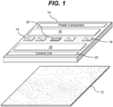
- FIG. 1 shows an illustrative ultraviolet illuminator 10 according to an embodiment for irradiating an object 12 that requires disinfection.
- the illuminator 10 can include a first set of radiation sources 14 and a second set of radiation sources 16 for irradiating the object 12. It is understood that first and second set of radiation sources 14, 16, along with other features of the illuminator 10, can be located at any location on the surface of the illuminator 10 and the depiction in FIG. 1 is on an example of one configuration. To this extent, it is understood that the particular arrangement, sizes, quantities, etc., of the illustrative components of the illuminator 10 depicted in FIG. 1 is only illustrative of various arrangements, sizes, quantities, etc., of the components.
- the first set of radiation sources 14 and the second set of radiation sources 16 can comprise any combination of one or more ultraviolet radiation emitter.
- an ultraviolet radiation emitter can include, but are not limited to, high intensity ultraviolet lamps (e.g., high intensity mercury lamps), discharge lamps, ultraviolet LEDs, super luminescent LEDs, laser diodes, and/or the like.
- the ultraviolet radiation source can include a set of LEDs manufactured with one or more layers of materials selected from the group-III nitride material system (e.g., Al x In y Ga 1-x-y N, where 0 ⁇ x, y ⁇ 1, and x + y ⁇ 1 and/or alloys thereof).
- the ultraviolet radiation source can comprise one or more additional components (e.g., a wave guiding structure, a component for relocating and/or redirecting ultraviolet radiation emitter(s), etc.) to direct and/or deliver the emitted radiation to a particular location/area, in a particular direction, in a particular pattern, and/or the like.
- additional components e.g., a wave guiding structure, a component for relocating and/or redirecting ultraviolet radiation emitter(s), etc.
- Illustrative wave guiding structures can include, but are not limited to, a wave guide, a plurality of ultraviolet fibers, each of which terminates at an opening, a diffuser, and/or the like.
- the first set of radiation sources 14 can include ultraviolet radiation sources that operate in the ultraviolet wavelength range (e.g., 10 nm to 400 nm).
- the first set of radiation sources 14 can operate to emit radiation having a peak wavelength in or immediately adjacent to the UV-C wavelength range and are referred to as "UV-C sources" herein.
- the first set of radiation sources 14 can operate in the wavelength range of approximately 270 nm to approximately 290 nm.
- FIG. 1 shows two instances of the first set of radiation sources 14 on the illuminator 10, it is understood that the illuminator 10 can include any number of instances of the first set of radiation sources 14.
- each of the instances of the first set of radiation sources 14 can include any number of sources.
- each of the ultraviolet radiation sources in the first set of radiation sources 14 can operate at a different peak wavelength ( ⁇ ). In an embodiment, each of the ultraviolet radiation sources in the first set of radiation sources 14 can irradiate a different location of the object 12. In another embodiment, the first set of radiation sources 14 can all irradiate different locations on the object 12 but with relatively uniform radiation. In another embodiment, more than one ultraviolet radiation source in the first set of ultraviolet radiation sources 14 can irradiate a single location on the object 12 but each ultraviolet radiation source can operate at a different wavelength and/or intensity.
- the first set of radiation sources 14 can include a set of reflective optical elements in order to focus the ultraviolet radiation to specific locations on the object 12.
- the set of reflective optical elements can include one or more of: a lens, a set of lenses, a parabolic reflector, a wave-guiding structure, and/or the like.
- the optical elements can include UV transparent material.
- the second set of radiation sources 16 can include blue-UV radiation sources that operate in the blue-UV wavelength range of approximately 380 nm to approximately 420 nm.
- the second set of radiation sources 16 can operate at a higher intensity, with wider coverage that continuously operate over an extended period of time.
- the second set of radiation sources 16 operating in the blue-UV wavelength range can operate continuously for several days. Prolonged exposure to radiation in the blue-UV wavelength range results in sterilization due to generation of reactive oxygen species (ROS).
- ROS reactive oxygen species
- ROS are chemically reactive chemical species that contain oxygen. The ROS can disrupt the proliferation of microorganisms on the object 12 by binding to and oxidizing the microorganisms.
- both the first set of radiation sources 14 and the second set of radiation sources 16 can produce a distributed intensity over one or more areas of the object 12 that is located a distance away from the illuminator 10.
- the distance between the illuminator 10 and the object 12 can range from a few centimeters to several meters.
- irradiation of a location defines a region of the object 12 that is impinged by radiation, wherein the intensity of radiation deposited at the boundary of the region is at most 10% of the intensity of light deposited at the center of the region.
- the position of irradiated locations can be adjusted to result in separate locations over the surface of the object 12, wherein separate means that the intensity of radiation between each of the locations is no larger than 10% of the intensity in the center of the locations.
- these locations of irradiation can be designed to have relatively uniform radiation, with radiation intensity varying through the location by no more than several times (e.g., a factor of three or less) between any two points within the location.
- the illuminator 10 can also include a third set of radiation sources 18.
- the third set of radiation sources 18 can include sources of fluorescent radiation.
- the third set of radiation sources 18 can include visible radiation sources such as incandescent, fluorescent, laser, solid state, and/or the like radiation sources that operate at least partially in the wavelength range of 400 nm to 700 nm.
- the third set of radiation sources 18 can include a visible source of collimated light capable of irradiating a surface of the object 12 at a set of angles.
- the illuminator can include a sensor 20 (e.g., a visual camera) capable of detecting the intensity of the reflected light at the set of angles.
- the third set of radiation sources 18 can include infrared radiation sources such as blackbody, solid state, and/or the like radiation sources that emit radiation that is in the wavelength range of 700 nm to 1 millimeter (mm).
- the illuminator 10 can include any number of sensors 20.
- the illuminator 10 can include one or more of various types of sensors 20.
- the set of sensors 20 can be configured to measure a plurality of conditions associated with the radiation from any of the sets of radiation sources 14, 16, 18 or the object 12.
- the set of sensors 20 can include sensors to detect visible radiation, UV radiation (e.g., blue-UV, UV-C, and/or the like), infrared radiation, chemicals fluorescence, and/or the like.
- the set of sensors 20 can include one or more sensors configured to detect fluorescent light radiated by the microorganisms on the object 12.
- the set of sensors 20 can include one or more fluorescent radiation sensors configured to detect fluorescent radiation induced on the surface of the object 12 by one or more of the sets of radiation sources 14, 16, 18.
- the third set of radiation sources 18 can include one or more visible radiation sources and the set of sensors 20 can include a visual camera configured to monitor the conditions of the object 12.
- the visual camera can detect changes in the surface appearance of the object 12 (e.g., changes in color, mildew growth, presence of dirt particles, changes in reflective or scattering properties of the surface, and/or the like).
- the set of sensors 20 can also include environmental condition sensors, such as a temperature sensor, a humidity sensor, a gas sensor, and/or the like.
- the object 12 can include a photo-catalyst, such as titanium dioxide (TiO 2 ), copper, silver, copper/silver particles., and/or the like. Such a photo-catalyst can further disrupt the growth and proliferation of microorganisms on the object 12.
- a photo-catalyst such as titanium dioxide (TiO 2 ), copper, silver, copper/silver particles., and/or the like.
- the illuminator 10 includes a control unit 22 that is configured to control and/or adjust the set of radiation sources 14, 16, 18 and the set of sensors 20.
- the control unit 22 can control and/or adjust the set of radiation sources 14, 16, 18 according to a plurality of radiation settings.
- the plurality of radiation settings can be based upon various environmental conditions in which the object 12 is placed (e.g., the location of the object 12, and/or the like), various attributes regarding the object 12 and/or the area surrounding the object 12 determined by the set of sensors 20, and/or the like.
- the controller 22 can determine a set of attributes regarding the object 12 and/or the area surrounding the object 12 and adjust the plurality of radiation settings of the set of radiation sources 14, 16, 18 and the set of sensors 20 to achieve a target set of attributes for the object 12 and/or the area surrounding the object 12.
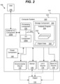
- FIG. 2 shows a schematic of an illustrative system 100 that can be implemented with any of the embodiments described in conjunction with FIG. 1 according to an embodiment.
- the system 100 is shown including the illuminator 110 that includes the set of UV-C sources 114, the set of blue-UV sources 116, the set of sensors 120, and a set of environmental devices 130.
- the third set of radiation sources 118 ( FIG. 1 ) are not shown for clarity, but it is understood that they can be included in the illuminator 110.
- the system 100 can include the control unit 122 for controlling and adjusting the plurality of radiation settings for the set of UV-C sources 114 and the set of blue-UV sources 116 and controlling and receiving data from the set of sensors 120.
- the control unit 122 can be implemented as a computer system 220 including an analysis program 230, which makes the computer system 220 operable to manage the various components in the illuminator 110 in the manner described herein.
- the analysis program 230 can enable the computer system 220 to operate the set of UV-C sources 114 and the set of blue-UV sources 116 in order to generate and direct ultraviolet radiation towards the object 112.
- the computer system 220 can also process data corresponding to one or more attributes regarding the object, which can be acquired by the set of sensors 120, and/or an ultraviolet radiation history stored as object data 240.
- the computer system 220 can individually control each ultraviolet radiation source in the set of UV-C sources 114 and the set of blue-UV sources 116 and each individual sensor in the set of sensors 120 and/or control two or more of the ultraviolet radiation sources and the sensors as a group.
- the ultraviolet radiation sources in the illuminator 110 can emit ultraviolet radiation of substantially the same wavelength or of multiple distinct wavelengths.
- the computer system 220 can acquire data from at least one of the sensors in the set of sensors 120 regarding one or more attributes of the object 112 and generate data 240 for further processing.
- the data 240 can include information regarding a presence of an object 112, a weight of an object 112, a microorganism concentration and/or location on the object 112, a size of an object 112, and/or the like.
- the computer system 220 can use the data 240 to control one or more aspects of the ultraviolet radiation generated by the set of UV-C sources 114 and/or the set of blue-UV sources 116 during an illumination period.
- one or more aspects of the operation of the ultraviolet radiation sources in the set of UV-C sources 114 and the set of blue-UV sources 116 can be controlled or adjusted by a user 102 via an external interface I/O component 226B.
- the external interface I/O component 226B can be located on the exterior of the illuminator 110, and used to allow the user 102 to control (e.g., selectively turn on/off) the ultraviolet radiation sources 114, 116.
- the external interface I/O component 226B can include, for example, a touch screen that can selectively display user interface controls, such as control dials, which can enable the user 102 to adjust one or more of: an intensity, scheduling, and/or other operational properties of the set of ultraviolet radiation sources 114, 116 in the illuminator 110 (e.g., operating parameters, radiation characteristics).
- the external interface I/O component 226B could conceivably include a keyboard, a plurality of buttons, a joystick-like control mechanism, and/or the like, which can enable the user 102 to control one or more aspects of the operation of the set of ultraviolet radiation sources 114, 116.
- the external interface I/O component 226B also can include any combination of various output devices (e.g., an LED, a visual display), which can be operated by the computer system 220 to provide status information pertaining to the illumination period of the object for use by the user 102.
- the external interface I/O component 226B can include one or more LEDs for emitting a visual light for the user 102, e.g., to indicate a status of the illumination period.
- the external interface I/O component 226B can include a speaker for providing an alarm (e.g., an auditory signal), e.g., for signaling that ultraviolet radiation is being generated or that the object had been illuminated by ultraviolet radiation.
- the computer system 220 is shown including a processing component 222 (e.g., one or more processors), a storage component 224 (e.g., a storage hierarchy), an input/output (I/O) component 226A (e.g., one or more I/O interfaces and/or devices), and a communications pathway 228.
- the processing component 222 executes program code, such as the analysis program 230, which is at least partially fixed in the storage component 224. While executing program code, the processing component 222 can process data, which can result in reading and/or writing transformed data from/to the storage component 224 and/or the I/O component 226A for further processing.
- the pathway 228 provides a communications link between each of the components in the computer system 220.
- the I/O component 226A and/or the external interface I/O component 226B can comprise one or more human I/O devices, which enable a human user 102 to interact with the computer system 220 and/or one or more communications devices to enable a system user 102 to communicate with the computer system 220 using any type of communications link.
- the analysis program 230 can manage a set of interfaces (e.g., graphical user interface(s), application program interface, and/or the like) that enable human and/or system users 102 to interact with the analysis program 230.
- the analysis program 230 can manage (e.g., store, retrieve, create, manipulate, organize, present, etc.) the data, such as the object data 240, using any solution.
- the computer system 220 can comprise one or more general purpose computing articles of manufacture (e.g., computing devices) capable of executing program code, such as the analysis program 230, installed thereon.
- program code means any collection of instructions, in any language, code or notation, that cause a computing device having an information processing capability to perform a particular function either directly or after any combination of the following: (a) conversion to another language, code or notation; (b) reproduction in a different material form; and/or (c) decompression.
- the analysis program 230 can be embodied as any combination of system software and/or application software.
- the analysis program 230 can be implemented using a set of modules 232.
- a module 232 can enable the computer system 220 to perform a set of tasks used by the analysis program 230, and can be separately developed and/or implemented apart from other portions of the analysis program 230.
- each computing device can have only a portion of the analysis program 230 fixed thereon (e.g., one or more modules 232).
- the computer system 220 and the analysis program 230 are only representative of various possible equivalent monitoring and/or control systems that may perform a process described herein with regard to the control unit, the ultraviolet radiation sources and the sensors.
- the functionality provided by the computer system 220 and the analysis program 230 can be at least partially implemented by one or more computing devices that include any combination of general and/or specific purpose hardware with or without program code.
- the hardware and program code if included, can be created using standard engineering and programming techniques, respectively.
- the control unit can be implemented without any computing device, e.g., using a closed loop circuit implementing a feedback control loop in which the outputs of one or more sensors are used as inputs to control the operation of the disinfecting pad.
- Illustrative aspects of the invention are further described in conjunction with the computer system 220. However, it is understood that the functionality described in conjunction therewith can be implemented by any type of monitoring and/or control system.
- the computing devices can communicate over any type of communications link.
- the computer system 220 can communicate with one or more other computer systems, such as the user 102, using any type of communications link.
- the communications link can comprise any combination of various types of wired and/or wireless links; comprise any combination of one or more types of networks; and/or utilize any combination of various types of transmission techniques and protocols.
- the power source 140 can take the form of one or more batteries, a vibration power generator that can generate power based on magnetic inducted oscillations or stresses developed on a piezoelectric crystal, a wall plug for accessing electrical power supplied from a grid, and/or the like.
- the power source can include a super capacitor that is rechargeable.
- Other power components that are suitable for use as the power source can include solar, a mechanical energy to electrical energy converter such as a rechargeable device, etc.
- control unit 122 can detect changes imparted to the object 12 from the set of radiation sources 114, 116 as a function of data determined by the set of sensors 120.
- the control unit 122 can detect the changes as a function of the data associated with the irradiation by the set of UV-C sources 114 and the blue-UV sources 116, and the data associated with environmental conditions surrounding the object 112.
- the data associated with the irradiation can include the frequency, intensity, dosage, duration, and wavelength from the radiation emitted by the set of UV-C sources 116 and the blue-UV sources 118.
- the changes that can be detected by the set of sensors 120 can include change in color, change in fluorescence from the surface, change in reflective properties of the surface, and/or the like.
- the object 112 can be a living organism, such as a person or an animal, and the system 100 can be used to apply a medical treatment.
- the illuminator 110 can include an environmental device 130 that detects a set of environmental conditions that can include various vital signs such as, blood pressure, heart rate, temperature, pulse, humidity of the skin, reflectivity of the skin, and/or the like.
- the changes that can be detected by the control unit 122 can include, but are not limited to, color changes of the human/animal skin, visual changes occurring over the surface of the human/animal skin (e.g., curing of the wounds, changes in the scarring tissue), and/or the like.
- the control unit 122 can detect the changes imparted to the object 112 from the data obtained from the set of sensors 120 using any solution.
- the set of sensors 120 can include a visual camera that is sensitive to visible radiation and the illuminator can include a third set of radiation sources 118 ( FIG. 1 ) that includes a source of visible radiation.
- the visual camera can acquire image data of the object 112 at a first instance of time and at a later instance of time under similar visible radiation conditions, assuming that the surface is not moved or otherwise physically altered.
- the control unit 122 can compare the image data to determine changes in color, surface optical properties, and/or the like. The changes in color can provide information regarding an overall microbial growth.
- the set of sensors 120 could also include a fluorescent detector to determine the presence of a fluorescent signal from the object 112.
- the third set of radiation sources 118 ( FIG. 1 ) can include fluorescent radiation sources and the set of sensors 120 can include a fluorescence sensor in order to acquire information regarding changes of the surface related to accumulation of fluorescent bacteria. Similar to the visual source and camera, the fluorescent sources and sensors can acquire data at set instances of time, which the control unit 122 can compare at such different instances.
- control unit 122 can also include a wireless transmitter and receiver that is configured to communicate with a remote location via Wi-Fi, BLUETOOTH, and/or the like.
- a remote location is a location that is apart from the system 100.
- a remote computer can be used to transmit operational instructions to the wireless transmitter and receiver. The operational instructions can be used to program functions performed and managed by the control unit 122.
- the wireless transmitter and receiver can transmit data calculations (e.g., changes), data from the sensors to the remote computer, to facilitate further use of the system 100 with the object 112.
- FIGS. 3A and 3B graphical representations that depict the operation of a scenario in which a first set of radiation sources and a second set of radiation sources, such as the first set of radiation sources 14 and the second set of radiation sources 16 shown in the embodiment shown in FIG. 1 , are operated as a function of time.
- ultraviolet radiation from the second set of the radiation sources e.g., blue-UV radiation
- determining whether there is any contamination of the object e.g., based on an amplitude of a fluorescent signal sensed by a fluorescent sensor, visual data from a visual camera, and/or the like).
- the object can be irradiated with a radiation source that is capable of eliciting a fluorescent signal if microbial activity is present.
- the amplitude of the fluorescent signal can indicate the level of contamination and/or the amount of microbial activity.
- the object can be irradiated by blue-UV radiation over a prolonged period of time that ranges from tens of minutes to tens of hours while determining whether there is a fluorescent signal. During this time, the control unit and the fluorescence sensor operate in conjunction to monitor the amount of contamination present on the surface of the object.
- FIG. 3B shows a sharp increase in the growth of microorganism activity as noted by reference element 310.
- the control unit will direct the first set of ultraviolet radiation sources (e.g., UV-C radiation) to perform the more intense ultraviolet irradiation treatment at the short burst of intensity that lasts at most a few minutes ( FIG 3A , reference number 330) starting at or shortly after time t.
- the first set of ultraviolet radiation sources e.g., UV-C radiation
- ultraviolet radiation e.g., UV-C radiation
- the blue-UV radiation from the second set of radiation sources is used to maintain microbial activity within limits over an extended period of time, while the UV-C radiation from the first set of radiation sources is designed to rapidly suppress microbial activity.
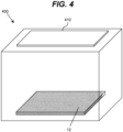
- FIG. 4 an illustrative enclosure 400 including an illuminator 410 according to an embodiment is shown.
- the enclosure 400 is shown as a box, it is understood that the enclosure 400 can by any shape and size.
- the interior of the enclosure 400 can include UV reflective and/or UV diffusively reflective materials, which are used to recycle the ultraviolet radiation within the enclosure 400.
- An embodiment of a diffusive ultraviolet reflective layer comprises a coating or thin film of a fluoropolymer.
- Examples of a fluoropolymer that are suitable as a diffusive ultraviolet reflective material that enables diffusive reflectivity can include, but are not limited to, expanding polytetrafluoroethylene (ePTFE) membrane (e.g., GORE ® DRP ® Diffuse Reflector Material), polytetrafluoroethylene (PTFE), and/or the like.
- ePTFE expanding polytetrafluoroethylene
- PTFE polytetrafluoroethylene
- Other examples of ultraviolet material that can be used to recycle radiation can include, but are not limited to, polished aluminum, Bragg reflective dielectric mirrors, omnidirectional mirrors comprising dielectric and metallic layers (e.g., aluminum), and/or the like.
- reflective surfaces can be combined with partially UV transparent surfaces designed for further reflection, recycling and light guiding UV radiation.
- such surfaces can comprise UV partially transparent material such as fluoropolymers, Al 2 O 3 , sapphire, SiO 2 , CaF 2 , MgF 2 , and/or the like.
- a surface can be formed of a partially UV transparent layer located on the interior side of the surface and a reflective layer located adjacent to the partially UV transparent layer on the exterior side of the surface.
- the object 12 to be disinfected is located within the enclosure 400.
- the illuminator 410 is located on a side of the enclosure 400 that is opposite of the side that the object 12 is located.
- the enclosure 400 can include an additional enclosure located therein designed for producing a hydroxyl group using ultraviolet radiation, a photo-catalyst (e.g., TiO 2 ), water vapor, and/or the like, wherein the hydroxyl group is used to further disinfect the object 12.
- a photo-catalyst e.g., TiO 2
- water vapor e.g., water vapor, and/or the like
Landscapes
- Health & Medical Sciences (AREA)
- Life Sciences & Earth Sciences (AREA)
- General Health & Medical Sciences (AREA)
- Animal Behavior & Ethology (AREA)
- Public Health (AREA)
- Veterinary Medicine (AREA)
- Epidemiology (AREA)
- Chemical & Material Sciences (AREA)
- Biomedical Technology (AREA)
- Engineering & Computer Science (AREA)
- Pathology (AREA)
- Nuclear Medicine, Radiotherapy & Molecular Imaging (AREA)
- Medicinal Chemistry (AREA)
- Molecular Biology (AREA)
- Analytical Chemistry (AREA)
- Biochemistry (AREA)
- General Physics & Mathematics (AREA)
- Immunology (AREA)
- Physics & Mathematics (AREA)
- Chemical Kinetics & Catalysis (AREA)
- Radiology & Medical Imaging (AREA)
- Apparatus For Disinfection Or Sterilisation (AREA)
- Investigating Materials By The Use Of Optical Means Adapted For Particular Applications (AREA)
Claims (15)
- Leuchte, die Folgendes umfasst:einen ersten Satz von ultravioletten Strahlungsquellen (14; 114),einen zweiten Satz von ultravioletten Strahlungsquellen (16; 116),einen Satz von Sensoren (20; 120) zum Erfassen von Daten, die sich auf eine Fläche eines Objekts (12; 112) beziehen, die vom ersten und vom zweiten Satz von ultravioletten Strahlungsquellen zu bestrahlen ist,und ein Steuersystem (22; 122), das dazu ausgelegt ist, einen Satz von Strahlungseinstellungen für den ersten (14; 114) und den zweiten (16; 116) Satz von ultravioletten Strahlungsquellen auf Basis der Daten, die vom Satz von Sensoren (20; 120) erfasst werden, zu steuern und anzupassen, wobei das Steuersystem (22; 122) den ersten Satz von ultravioletten Strahlungsquellen (16; 116) betreibt, um die Fläche des Objekts (12; 112) zu bestrahlen, um ein Maß mikrobieller Aktivität über die Zeit innerhalb eines Grenzwerts zu halten,dadurch gekennzeichnetdass jede ultraviolette Strahlungsquelle im ersten Satz von ultravioletten Strahlungsquellen (14; 114) mindestens eine lichtemittierende Diode beinhaltet, die in einem Wellenlängenbereich von etwa 270 Nanometer bis etwa 290 Nanometer betrieben wird,dass jede ultraviolette Strahlungsquelle im zweiten Satz von ultravioletten Strahlungsquellen (16; 116) mindestens eine lichtemittierende Diode beinhaltet, die in einem Wellenlängenbereich von etwa 380 Nanometer bis etwa 420 Nanometer betrieben wird, und dass das Steuersystem (22; 122) des ersten Satzes von ultravioletten Strahlungsquellen (14; 114) betrieben wird, um eine intensivere ultraviolette Strahlungsbehandlung in einem kurzen Intensitätsburst von höchstens einigen Minuten durchzuführen, um das Maß von mikrobieller Aktivität auf der Fläche des Objekts (12; 112) nur schnell zu unterdrücken, wenn das Maß von mikrobieller Aktivität einen vorbestimmten Verunreinigungsschwellwert überschreitet.
- Leuchte nach Anspruch 1, die ferner einen Satz von Strahlungsquellen (18; 118) umfasst, die dazu ausgelegt sind, die Fläche des Objekts (12; 112) mit einer Strahlung zu bestrahlen, die in der Lage ist, ein Fluoreszenzsignal auszulösen, wobei der Satz von Strahlungseinstellungen auf einer Amplitude des Fluoreszenzsignals basiert.
- Leuchte nach Anspruch 2, wobei der Satz von Sensoren (120) mindestens einen Fluoreszenzdetektor beinhaltet.
- Leuchte nach einem der Ansprüche 1 bis 3, wobei der Satz von Sensoren (120) eine visuelle Kamera beinhaltet, die dazu ausgelegt ist, eine Änderung der Fläche des Objekts zu detektieren.
- Leuchte nach Anspruch 4, wobei die Änderung der Fläche des Objekts mindestens eines von Folgendem beinhaltet: eine Änderung der Farbe, eine Änderung des Mehltauwachstums oder eine Änderung einer Menge von Schmutzpartikeln.
- Leuchte nach einem der Ansprüche 1 bis 5, die ferner ein Eingabesystem (226A) umfasst, das dazu ausgelegt ist, es einem Benutzer zu erlauben, mit dem Steuersystem zu interagieren, um den Satz von Strahlungseinstellungen manuell zu steuern.
- Leuchte nach einem der Ansprüche 1 bis 6, wobei der Satz von Strahlungseinstellungen in Reaktion auf das Detektieren, dass das Maß von mikrobieller Aktivität über dem vorbestimmten Verunreinigungsschwellwert liegt, das Ausschalten des zweiten Satzes von ultravioletten Strahlungsquellen (16, 116) und das Einschalten des ersten Satzes von ultravioletten Strahlungsquellen (14; 114) beinhaltet.
- Leuchte nach Anspruch 7, wobei der Satz von Strahlungseinstellungen in Reaktion darauf, dass das Maß von mikrobieller Aktivität unter dem vorbestimmten Verunreinigungsschwellwert liegt, das Einschalten des zweiten Satzes von ultravioletten Strahlungsquellen (16; 116) und das Ausschalten des ersten Satzes von ultravioletten Strahlungsquellen (14; 114) beinhaltet.
- Leuchte nach einem der Ansprüche 1 bis 8, wobei das Objekt (12; 112) ein lebender Organismus ist.
- System, das Folgendes umfasst:mindestens ein Objekt;eine Leuchte (10; 110), die dazu ausgelegt ist, das mindestens eine Objekt (12; 112) durch Richten einer ultravioletten Strahlung auf das mindestens eine Objekt zu desinfizieren, wobei die Leuchte eine Leuchte (10; 110) nach einem der Ansprüche 1 bis 8 umfasst.
- System nach Anspruch 10, wobei das mindestens eine Objekt einen Photokatalysator beinhaltet.
- System nach Anspruch 11, wobei der Photokatalysator mindestens eines von Folgendem umfasst: Titandioxid, Kupfer, Silber und Kupfer-/Silberpartikel.
- Gehäuse, das Folgendes umfasst:
eine Leuchte (410), die sich neben dem Gehäuse (400) befindet, wobei die Leuchte dazu ausgelegt ist, ultraviolette Strahlung innerhalb des Gehäuses zu richten, wobei die Leuchte eine Leuchte (410) nach einem der Ansprüche 1 bis 8 umfasst. - Gehäuse nach Anspruch 13, wobei Innenflächen des Gehäuses (400) ein ultraviolettes reflektierendes Material beinhalten, um die ultraviolette Strahlung im Gehäuse zu rezirkulieren.
- Gehäuse nach Anspruch 13 oder 14, das ferner ein Mittel zum Produzieren einer Hydroxylgruppe umfasst, um das Objekt zu desinfizieren.
Applications Claiming Priority (2)
| Application Number | Priority Date | Filing Date | Title |
|---|---|---|---|
| US201762576695P | 2017-10-25 | 2017-10-25 | |
| PCT/US2018/057505 WO2019084264A2 (en) | 2017-10-25 | 2018-10-25 | ULTRAVIOLET AND BLUE-ULTRAVIOLET LIGHT SOURCE LIGHTING DEVICE |
Publications (3)
| Publication Number | Publication Date |
|---|---|
| EP3701190A2 EP3701190A2 (de) | 2020-09-02 |
| EP3701190A4 EP3701190A4 (de) | 2021-07-28 |
| EP3701190B1 true EP3701190B1 (de) | 2025-04-02 |
Family
ID=66169106
Family Applications (1)
| Application Number | Title | Priority Date | Filing Date |
|---|---|---|---|
| EP18870125.4A Active EP3701190B1 (de) | 2017-10-25 | 2018-10-25 | Beleuchtungsvorrichtung mit ultravioletter und blau-ultravioletter lichtquelle |
Country Status (3)
| Country | Link |
|---|---|
| US (3) | US10688211B2 (de) |
| EP (1) | EP3701190B1 (de) |
| WO (1) | WO2019084264A2 (de) |
Families Citing this family (23)
| Publication number | Priority date | Publication date | Assignee | Title |
|---|---|---|---|---|
| US10787375B2 (en) | 2013-07-08 | 2020-09-29 | Sensor Electronics Technology, Inc. | Ultraviolet water disinfection system |
| US11166415B2 (en) | 2016-07-26 | 2021-11-09 | Sensor Electronic Technology, Inc. | Plant growth with radiation-based mildew and/or bacteria control |
| US11375595B2 (en) | 2016-09-30 | 2022-06-28 | Sensor Electronic Technology, Inc. | Controlling ultraviolet intensity over a surface of a light sensitive object |
| US11173221B2 (en) | 2017-10-31 | 2021-11-16 | Sensor Electronic Technology, Inc. | Ultraviolet disinfection for a water bottle |
| US10881755B2 (en) | 2017-12-31 | 2021-01-05 | Sensor Electronic Technology, Inc. | Ultraviolet illumination with optical elements |
| US11207435B2 (en) | 2018-01-31 | 2021-12-28 | Sensor Electronic Technology, Inc. | Humidifier disinfection using ultraviolet light |
| US11608279B2 (en) | 2018-02-28 | 2023-03-21 | Sensor Electronic Technology, Inc. | Ultraviolet irradiation of fluids |
| US11174174B2 (en) | 2018-03-31 | 2021-11-16 | Sensor Electronic Technology, Inc. | Ultraviolet irradiation of a flowing fluid |
| US11027319B2 (en) | 2018-03-31 | 2021-06-08 | Sensor Electronic Technology, Inc. | Illumination using multiple light sources |
| US10881751B2 (en) | 2018-03-31 | 2021-01-05 | Sensor Electronic Technology, Inc. | Ultraviolet irradiation of food handling instruments |
| SE544362C2 (en) * | 2019-11-18 | 2022-04-19 | Lightlab Sweden Ab | A system for treating a surface comprising a uv lighting arrangement |
| CA3172386A1 (en) | 2020-03-03 | 2021-09-10 | Helios Shield Ltd | Combination ultra-violet a (uva) and ultra-violet c (uvc) system for reduction and inhibition of growth of pathogens |
| US12458715B2 (en) | 2020-03-03 | 2025-11-04 | Helios Shield Ltd. | Ultra-violet A (UVA) and ultra-violet C (UVC) system and methods for inactivation, reduction and inhibition of growth of coronavirus |
| EP4146289A4 (de) * | 2020-05-04 | 2025-02-26 | 2449049 Ontario Inc. | Uva- und uvc-system sowie verfahren zur inaktivierung, reduktion und hemmung des wachstums von coronavirus |
| US12076453B2 (en) | 2020-08-17 | 2024-09-03 | Prostar Technologies, Inc. | Portable UV sanitization device |
| EP3957333A1 (de) | 2020-08-19 | 2022-02-23 | Analytik Jena GmbH | Uv-modul, system und verfahren zur deaktivierung von biologisch kontaminierten oberflächen in einem inneraum eines geräts |
| IT202000029891A1 (it) * | 2020-12-04 | 2022-06-04 | Thegg Domotica S R L | Metodo co-creativo e dispositivo innovativo per la sanificazione a led |
| GB2602267B (en) * | 2020-12-18 | 2025-04-02 | Dyson Technology Ltd | Storage case for a portable device |
| US12186438B2 (en) | 2021-04-08 | 2025-01-07 | Sony Group Corporation | Apparatus and method for disinfection of object |
| CA3249270A1 (en) | 2022-01-20 | 2023-07-27 | Population Lights Inc | SYSTEMS, DEVICES AND METHODS FOR ASSESSING GERMICIDAL RISKS IN ENVIRONMENTS AND GENERATING ENVIRONMENTAL PROTECTION PLANS FOR ENVIRONMENTAL DISINFECTION |
| CN115089737A (zh) * | 2022-07-22 | 2022-09-23 | 郑棚 | 大面积区域式智能联动二合一消毒照明灯系统 |
| CN115054707A (zh) * | 2022-07-22 | 2022-09-16 | 郑棚 | 紫外线智能消毒照明装置 |
| FR3158892A1 (fr) * | 2024-02-02 | 2025-08-08 | Ebica - Etienne Business Intelligence Consulting Agency | Procédé d’irradiation multi-fréquences contrôlée d’une surface, et système correspondant |
Family Cites Families (67)
| Publication number | Priority date | Publication date | Assignee | Title |
|---|---|---|---|---|
| US6063591A (en) * | 1997-05-14 | 2000-05-16 | 3M Innovative Properties Company | System for measuring the efficacy of a sterilization cycle |
| IL150914A (en) * | 2002-07-25 | 2014-04-30 | Zamir Tribelsky | Method for hydro-optronic photochemical treatment of liquids |
| KR20080076911A (ko) | 2005-10-24 | 2008-08-20 | 클린 라이트 비브이 | Uv-c 광을 이용한 살아있는 식물 또는 식물 일부분,또는 버섯의 처리 방법 |
| US7634996B2 (en) | 2006-02-14 | 2009-12-22 | Sensor Electronic Technology, Inc. | Ultraviolet radiation sterilization |
| US7553456B2 (en) | 2006-03-02 | 2009-06-30 | Sensor Electronic Technology, Inc. | Organism growth suppression using ultraviolet radiation |
| US20080310996A1 (en) * | 2007-04-13 | 2008-12-18 | Kim Darrick S H L | Germicidal Floor System (GFS) |
| US20090314308A1 (en) | 2007-04-13 | 2009-12-24 | Kim Darrick S H L | Germicidal Floor, Germicidal Foot, And Hand Cleaning System |
| US8277734B2 (en) | 2008-05-12 | 2012-10-02 | Sensor Electronic Technology, Inc. | Biological activity monitoring and/or suppression |
| CN102325727A (zh) | 2009-02-23 | 2012-01-18 | 罗姆股份有限公司 | 净水器 |
| US8980178B2 (en) | 2009-05-23 | 2015-03-17 | Sensor Electronic Technology, Inc. | Medium treatment using ultraviolet light |
| US8387405B2 (en) * | 2010-02-26 | 2013-03-05 | Edward Johnson | Antimicrobial ultraviolet light system for refrigerator sanitation |
| US20110291995A1 (en) * | 2010-05-25 | 2011-12-01 | Industrial Technology Research Institute | Sterilizing device and manufacturing method for sterilizing device |
| US10046073B2 (en) * | 2010-06-01 | 2018-08-14 | Bluemorph, Llc | Portable UV devices, systems and methods of use and manufacturing |
| EP2654806B1 (de) | 2010-12-22 | 2019-05-22 | Ortner Cleanroom Engineering GmbH | Fotodynamische steuerung von mikrobiellem wachstum auf oberflächen |
| US8779391B2 (en) * | 2011-03-03 | 2014-07-15 | Teckni-Corp | Sterilization system with ultraviolet emitter for eradicating biological contaminants |
| US20130048545A1 (en) | 2011-08-23 | 2013-02-28 | Maxim S. Shatalov | Water Disinfection Using Deep Ultraviolet Light |
| US9061082B2 (en) | 2012-04-16 | 2015-06-23 | Sensor Electronic Technology, Inc. | Ultraviolet-based sterilization |
| US9999782B2 (en) | 2012-04-16 | 2018-06-19 | Sensor Electronic Technology, Inc. | Ultraviolet-based sterilization |
| US20180104368A1 (en) | 2012-04-16 | 2018-04-19 | Sensor Electronic Technology, Inc. | Ultraviolet-Based Sterilization |
| KR101338130B1 (ko) * | 2012-05-09 | 2013-12-06 | 전자부품연구원 | 실내 공기 살균 기능을 겸비한 조명 장치, 그리고 실내 공기 살균 및 조광 방법 |
| US9724441B2 (en) | 2012-08-28 | 2017-08-08 | Sensor Electronic Technology, Inc. | Storage device including target UV illumination ranges |
| US10688210B2 (en) | 2012-08-28 | 2020-06-23 | Sensor Electronic Technology, Inc. | Storage device including ultraviolet illumination |
| CN105050433A (zh) * | 2012-08-28 | 2015-11-11 | 传感器电子技术股份有限公司 | 用于消毒的紫外线系统 |
| US9919068B2 (en) * | 2012-08-28 | 2018-03-20 | Sensor Electronic Technology, Inc. | Storage device including ultraviolet illumination |
| US9981051B2 (en) | 2012-08-28 | 2018-05-29 | Sensor Electronic Technology, Inc. | Ultraviolet gradient sterilization, disinfection, and storage system |
| US9750830B2 (en) | 2012-08-28 | 2017-09-05 | Sensor Electronic Technology, Inc. | Multi wave sterilization system |
| US9878061B2 (en) | 2012-08-28 | 2018-01-30 | Sensor Electronic Technology, Inc. | Ultraviolet system for disinfection |
| US9707307B2 (en) | 2012-08-28 | 2017-07-18 | Sensor Electronic Technology, Inc. | Ultraviolet system for disinfection |
| US10646603B2 (en) | 2012-08-28 | 2020-05-12 | Sensor Electronic Technology, Inc. | Multi wave sterilization system |
| CN104736261B (zh) | 2012-08-28 | 2017-06-16 | 传感器电子技术股份有限公司 | 包括紫外线照明的存储系统 |
| US10383964B2 (en) | 2012-08-28 | 2019-08-20 | Sensor Electronic Technology, Inc. | Storage device including ultraviolet illumination |
| US10441670B2 (en) | 2012-08-28 | 2019-10-15 | Sensor Electronic Technology, Inc. | Storage device including ultraviolet illumination |
| US9210775B2 (en) | 2012-10-31 | 2015-12-08 | General Electric Company | Method and system for storage of perishable items |
| WO2014106196A1 (en) | 2012-12-31 | 2014-07-03 | Sensor Electronic Technology, Inc. | Electronic gadget disinfection |
| US9974877B2 (en) | 2012-12-31 | 2018-05-22 | Sensor Electronic Technology, Inc. | Electronic gadget disinfection |
| US10442704B2 (en) | 2013-01-18 | 2019-10-15 | Sensor Electronic Technology, Inc. | Ultraviolet fluid disinfection system with feedback sensor |
| US9801965B2 (en) | 2013-03-18 | 2017-10-31 | Sensor Electronic Technology, Inc. | Ultraviolet disinfection case |
| DE112014001503B4 (de) | 2013-03-18 | 2022-06-23 | Sensor Electronic Technology, Inc. | Ultraviolett-Desinfektionsgehäuse |
| WO2014186741A1 (en) * | 2013-05-17 | 2014-11-20 | Germitec SA | Methods, systems, and devices for high-level disinfection |
| US9802840B2 (en) | 2013-07-08 | 2017-10-31 | Sensor Electronic Technology, Inc. | Ultraviolet water disinfection system |
| US10040699B2 (en) | 2013-07-08 | 2018-08-07 | Sensor Electronics Technology, Inc. | Ultraviolet water disinfection system |
| DE102015108773B4 (de) | 2014-06-03 | 2024-07-04 | Sensor Electronic Technology, Inc. | Ultraviolett-transparente Umhüllung |
| US10099944B2 (en) | 2014-06-03 | 2018-10-16 | Sensor Electronic Technology, Inc. | Ultraviolet transparent enclosure |
| US9511159B2 (en) * | 2014-07-02 | 2016-12-06 | At&T Intellectual Property I, L.P. | Method and apparatus for sterilizing a surface |
| US9687577B2 (en) | 2014-09-13 | 2017-06-27 | Sensor Electronic Technology, Inc. | Ultraviolet illuminator for footwear treatment |
| US10426852B2 (en) | 2014-10-15 | 2019-10-01 | Sensor Electronics Technology, Inc. | Ultraviolet-based detection and sterilization |
| CN107073146B (zh) | 2014-10-15 | 2020-09-25 | 首尔伟傲世有限公司 | 基于紫外的检测和灭菌 |
| US10166307B2 (en) | 2014-10-28 | 2019-01-01 | Sensor Electronic Technology, Inc. | Adhesive device with ultraviolet element |
| US9757486B2 (en) | 2014-11-06 | 2017-09-12 | Sensor Electronic Technology, Inc. | Ultraviolet-based bathroom surface sanitization |
| KR101704502B1 (ko) | 2015-04-27 | 2017-02-09 | (주)애니스마트 | 건조·살균·색온도조절 기능을 갖는 네트워크형 스마트 led 복합등기구 |
| US9987383B2 (en) | 2015-05-07 | 2018-06-05 | Sensor Electronic Technology, Inc. | Medical device treatment |
| US20170057842A1 (en) | 2015-09-01 | 2017-03-02 | Sensor Electronic Technology, Inc. | Fluid Disinfection Using Ultraviolet Light |
| US10004821B2 (en) | 2015-10-13 | 2018-06-26 | Sensor Electronic Technology, Inc. | Ultraviolet treatment of light absorbing liquids |
| US10688312B2 (en) | 2015-12-31 | 2020-06-23 | Sensor Electronic Technology, Inc. | Medical device with radiation delivery |
| US10548332B2 (en) | 2016-02-29 | 2020-02-04 | Sensor Electronic Technology, Inc. | Disinfection of grain using ultraviolet radiation |
| US10687598B2 (en) * | 2016-02-29 | 2020-06-23 | Sensor Electronic Technology, Inc. | Ultraviolet razor blade treatment |
| US10869943B2 (en) | 2016-03-31 | 2020-12-22 | Sensor Electronic Technology, Inc. | Treatment of fluid transport conduit with ultraviolet radiation |
| US10517974B2 (en) | 2016-04-07 | 2019-12-31 | Sensor Electronic Technology, Inc. | Ultraviolet surface illumination system |
| US10624978B2 (en) | 2016-07-26 | 2020-04-21 | Sensor Electronic Technology, Inc. | Ultraviolet-based mildew control |
| US10433493B2 (en) | 2016-09-30 | 2019-10-08 | Sensor Electronic Technology, Inc. | Controlling ultraviolet intensity over a surface of a light sensitive object |
| WO2018080805A1 (en) * | 2016-10-24 | 2018-05-03 | Phoseon Technology, Inc. | Systems and methods for bio-inactivation |
| US10543290B2 (en) | 2016-12-29 | 2020-01-28 | Sensor Electronic Technology, Inc. | Ultraviolet illuminator for object disinfection |
| US10994040B2 (en) | 2017-05-26 | 2021-05-04 | Sensor Electronic Technology, Inc. | Surface treatment with ultraviolet light |
| US10751663B2 (en) | 2017-07-31 | 2020-08-25 | Sensor Electronic Technology, Inc. | Ultraviolet treatment of volatile organic compounds |
| US10717659B2 (en) | 2017-09-30 | 2020-07-21 | Sensor Electronic Technology, Inc. | Ultraviolet irradiation of aquatic environment |
| US11124750B2 (en) | 2017-09-30 | 2021-09-21 | Sensor Electronic Technology, Inc. | Ultraviolet irradiation of fluids |
| US11357998B2 (en) | 2017-09-30 | 2022-06-14 | Sensor Electronic Technology, Inc. | Wearable ultraviolet light phototherapy device |
-
2018
- 2018-10-25 EP EP18870125.4A patent/EP3701190B1/de active Active
- 2018-10-25 US US16/170,617 patent/US10688211B2/en active Active
- 2018-10-25 WO PCT/US2018/057505 patent/WO2019084264A2/en not_active Ceased
-
2020
- 2020-05-19 US US16/878,509 patent/US11266759B2/en active Active
-
2022
- 2022-03-07 US US17/688,218 patent/US12011514B2/en active Active
Also Published As
| Publication number | Publication date |
|---|---|
| US20190117811A1 (en) | 2019-04-25 |
| WO2019084264A2 (en) | 2019-05-02 |
| US11266759B2 (en) | 2022-03-08 |
| US20220184260A1 (en) | 2022-06-16 |
| US12011514B2 (en) | 2024-06-18 |
| WO2019084264A3 (en) | 2019-06-13 |
| EP3701190A4 (de) | 2021-07-28 |
| US10688211B2 (en) | 2020-06-23 |
| US20200276345A1 (en) | 2020-09-03 |
| EP3701190A2 (de) | 2020-09-02 |
Similar Documents
| Publication | Publication Date | Title |
|---|---|---|
| US12011514B2 (en) | Illuminator with ultraviolet and blue-ultraviolet light source | |
| US10881755B2 (en) | Ultraviolet illumination with optical elements | |
| US10881751B2 (en) | Ultraviolet irradiation of food handling instruments | |
| US10456487B2 (en) | Device treatment | |
| US10543290B2 (en) | Ultraviolet illuminator for object disinfection | |
| US10456488B2 (en) | Ultraviolet transparent structure for ultraviolet illumination using scattered and focused radiation | |
| US10556026B2 (en) | Ultraviolet transparent structure for ultraviolet illumination | |
| US10286094B2 (en) | Flexible article for UV disinfection | |
| CA2787266C (en) | Systems and methods for emitting radiant energy | |
| US10717659B2 (en) | Ultraviolet irradiation of aquatic environment | |
| US11174174B2 (en) | Ultraviolet irradiation of a flowing fluid | |
| US11656387B2 (en) | Light emitting device for emitting diffuse light |
Legal Events
| Date | Code | Title | Description |
|---|---|---|---|
| STAA | Information on the status of an ep patent application or granted ep patent |
Free format text: STATUS: THE INTERNATIONAL PUBLICATION HAS BEEN MADE |
|
| PUAI | Public reference made under article 153(3) epc to a published international application that has entered the european phase |
Free format text: ORIGINAL CODE: 0009012 |
|
| STAA | Information on the status of an ep patent application or granted ep patent |
Free format text: STATUS: REQUEST FOR EXAMINATION WAS MADE |
|
| 17P | Request for examination filed |
Effective date: 20200525 |
|
| AK | Designated contracting states |
Kind code of ref document: A2 Designated state(s): AL AT BE BG CH CY CZ DE DK EE ES FI FR GB GR HR HU IE IS IT LI LT LU LV MC MK MT NL NO PL PT RO RS SE SI SK SM TR |
|
| AX | Request for extension of the european patent |
Extension state: BA ME |
|
| DAV | Request for validation of the european patent (deleted) | ||
| DAX | Request for extension of the european patent (deleted) | ||
| A4 | Supplementary search report drawn up and despatched |
Effective date: 20210629 |
|
| RIC1 | Information provided on ipc code assigned before grant |
Ipc: F21V 33/00 20060101AFI20210623BHEP Ipc: F21V 23/04 20060101ALI20210623BHEP Ipc: F21W 131/205 20060101ALI20210623BHEP |
|
| STAA | Information on the status of an ep patent application or granted ep patent |
Free format text: STATUS: EXAMINATION IS IN PROGRESS |
|
| 17Q | First examination report despatched |
Effective date: 20220620 |
|
| REG | Reference to a national code |
Ref country code: DE Ref legal event code: R079 Free format text: PREVIOUS MAIN CLASS: F21V0033000000 Ipc: A61L0002000000 Ref country code: DE Ref legal event code: R079 Ref document number: 602018080808 Country of ref document: DE Free format text: PREVIOUS MAIN CLASS: F21V0033000000 Ipc: A61L0002000000 |
|
| GRAP | Despatch of communication of intention to grant a patent |
Free format text: ORIGINAL CODE: EPIDOSNIGR1 |
|
| STAA | Information on the status of an ep patent application or granted ep patent |
Free format text: STATUS: GRANT OF PATENT IS INTENDED |
|
| RIC1 | Information provided on ipc code assigned before grant |
Ipc: G01N 21/64 20060101ALI20230321BHEP Ipc: A61N 5/00 20060101ALI20230321BHEP Ipc: A61L 2/00 20060101AFI20230321BHEP |
|
| INTG | Intention to grant announced |
Effective date: 20230419 |
|
| GRAJ | Information related to disapproval of communication of intention to grant by the applicant or resumption of examination proceedings by the epo deleted |
Free format text: ORIGINAL CODE: EPIDOSDIGR1 |
|
| GRAS | Grant fee paid |
Free format text: ORIGINAL CODE: EPIDOSNIGR3 |
|
| GRAJ | Information related to disapproval of communication of intention to grant by the applicant or resumption of examination proceedings by the epo deleted |
Free format text: ORIGINAL CODE: EPIDOSDIGR1 |
|
| GRAL | Information related to payment of fee for publishing/printing deleted |
Free format text: ORIGINAL CODE: EPIDOSDIGR3 |
|
| STAA | Information on the status of an ep patent application or granted ep patent |
Free format text: STATUS: EXAMINATION IS IN PROGRESS |
|
| INTC | Intention to grant announced (deleted) | ||
| GRAP | Despatch of communication of intention to grant a patent |
Free format text: ORIGINAL CODE: EPIDOSNIGR1 |
|
| STAA | Information on the status of an ep patent application or granted ep patent |
Free format text: STATUS: GRANT OF PATENT IS INTENDED |
|
| INTG | Intention to grant announced |
Effective date: 20241025 |
|
| GRAS | Grant fee paid |
Free format text: ORIGINAL CODE: EPIDOSNIGR3 |
|
| GRAA | (expected) grant |
Free format text: ORIGINAL CODE: 0009210 |
|
| STAA | Information on the status of an ep patent application or granted ep patent |
Free format text: STATUS: THE PATENT HAS BEEN GRANTED |
|
| AK | Designated contracting states |
Kind code of ref document: B1 Designated state(s): AL AT BE BG CH CY CZ DE DK EE ES FI FR GB GR HR HU IE IS IT LI LT LU LV MC MK MT NL NO PL PT RO RS SE SI SK SM TR |
|
| REG | Reference to a national code |
Ref country code: GB Ref legal event code: FG4D |
|
| REG | Reference to a national code |
Ref country code: CH Ref legal event code: EP |
|
| REG | Reference to a national code |
Ref country code: IE Ref legal event code: FG4D |
|
| REG | Reference to a national code |
Ref country code: DE Ref legal event code: R096 Ref document number: 602018080808 Country of ref document: DE |
|
| U01 | Request for unitary effect filed |
Effective date: 20250502 |
|
| U04 | Request for unitary effect rejected |
Effective date: 20250624 |
|
| REG | Reference to a national code |
Ref country code: NL Ref legal event code: MP Effective date: 20250402 |
|
| PG25 | Lapsed in a contracting state [announced via postgrant information from national office to epo] |
Ref country code: NL Free format text: LAPSE BECAUSE OF FAILURE TO SUBMIT A TRANSLATION OF THE DESCRIPTION OR TO PAY THE FEE WITHIN THE PRESCRIBED TIME-LIMIT Effective date: 20250402 |
|
| PG25 | Lapsed in a contracting state [announced via postgrant information from national office to epo] |
Ref country code: ES Free format text: LAPSE BECAUSE OF FAILURE TO SUBMIT A TRANSLATION OF THE DESCRIPTION OR TO PAY THE FEE WITHIN THE PRESCRIBED TIME-LIMIT Effective date: 20250402 Ref country code: FI Free format text: LAPSE BECAUSE OF FAILURE TO SUBMIT A TRANSLATION OF THE DESCRIPTION OR TO PAY THE FEE WITHIN THE PRESCRIBED TIME-LIMIT Effective date: 20250402 |
|
| REG | Reference to a national code |
Ref country code: LT Ref legal event code: MG9D |
|
| PG25 | Lapsed in a contracting state [announced via postgrant information from national office to epo] |
Ref country code: NO Free format text: LAPSE BECAUSE OF FAILURE TO SUBMIT A TRANSLATION OF THE DESCRIPTION OR TO PAY THE FEE WITHIN THE PRESCRIBED TIME-LIMIT Effective date: 20250702 Ref country code: GR Free format text: LAPSE BECAUSE OF FAILURE TO SUBMIT A TRANSLATION OF THE DESCRIPTION OR TO PAY THE FEE WITHIN THE PRESCRIBED TIME-LIMIT Effective date: 20250703 |
|
| PG25 | Lapsed in a contracting state [announced via postgrant information from national office to epo] |
Ref country code: PL Free format text: LAPSE BECAUSE OF FAILURE TO SUBMIT A TRANSLATION OF THE DESCRIPTION OR TO PAY THE FEE WITHIN THE PRESCRIBED TIME-LIMIT Effective date: 20250402 |
|
| PG25 | Lapsed in a contracting state [announced via postgrant information from national office to epo] |
Ref country code: BG Free format text: LAPSE BECAUSE OF FAILURE TO SUBMIT A TRANSLATION OF THE DESCRIPTION OR TO PAY THE FEE WITHIN THE PRESCRIBED TIME-LIMIT Effective date: 20250402 |
|
| PG25 | Lapsed in a contracting state [announced via postgrant information from national office to epo] |
Ref country code: HR Free format text: LAPSE BECAUSE OF FAILURE TO SUBMIT A TRANSLATION OF THE DESCRIPTION OR TO PAY THE FEE WITHIN THE PRESCRIBED TIME-LIMIT Effective date: 20250402 |
|
| PG25 | Lapsed in a contracting state [announced via postgrant information from national office to epo] |
Ref country code: RS Free format text: LAPSE BECAUSE OF FAILURE TO SUBMIT A TRANSLATION OF THE DESCRIPTION OR TO PAY THE FEE WITHIN THE PRESCRIBED TIME-LIMIT Effective date: 20250702 |
|
| PG25 | Lapsed in a contracting state [announced via postgrant information from national office to epo] |
Ref country code: IS Free format text: LAPSE BECAUSE OF FAILURE TO SUBMIT A TRANSLATION OF THE DESCRIPTION OR TO PAY THE FEE WITHIN THE PRESCRIBED TIME-LIMIT Effective date: 20250802 |