EP3701123B1 - Surveillance d'état de joint d'étanchéité - Google Patents
Surveillance d'état de joint d'étanchéité Download PDFInfo
- Publication number
- EP3701123B1 EP3701123B1 EP18888557.8A EP18888557A EP3701123B1 EP 3701123 B1 EP3701123 B1 EP 3701123B1 EP 18888557 A EP18888557 A EP 18888557A EP 3701123 B1 EP3701123 B1 EP 3701123B1
- Authority
- EP
- European Patent Office
- Prior art keywords
- sealing element
- seal
- pressure
- annular
- annular packer
- Prior art date
- Legal status (The legal status is an assumption and is not a legal conclusion. Google has not performed a legal analysis and makes no representation as to the accuracy of the status listed.)
- Active
Links
- 238000012544 monitoring process Methods 0.000 title claims description 27
- 238000007789 sealing Methods 0.000 claims description 306
- 238000005553 drilling Methods 0.000 claims description 66
- 238000005461 lubrication Methods 0.000 claims description 56
- 239000000463 material Substances 0.000 claims description 42
- 238000000034 method Methods 0.000 claims description 25
- 229920001971 elastomer Polymers 0.000 claims description 11
- 238000002955 isolation Methods 0.000 claims description 10
- 230000008859 change Effects 0.000 claims description 7
- 239000000806 elastomer Substances 0.000 claims description 7
- 239000011159 matrix material Substances 0.000 claims description 5
- 229920000459 Nitrile rubber Polymers 0.000 claims description 4
- 229920006168 hydrated nitrile rubber Polymers 0.000 claims description 4
- 229920000642 polymer Polymers 0.000 claims description 4
- 229920001343 polytetrafluoroethylene Polymers 0.000 claims description 4
- 239000004810 polytetrafluoroethylene Substances 0.000 claims description 4
- 229920002635 polyurethane Polymers 0.000 claims description 4
- 239000004814 polyurethane Substances 0.000 claims description 4
- 239000004699 Ultra-high molecular weight polyethylene Substances 0.000 claims description 3
- 150000002825 nitriles Chemical class 0.000 claims description 3
- -1 polytetrafluoroethylene Polymers 0.000 claims description 3
- 229920000785 ultra high molecular weight polyethylene Polymers 0.000 claims description 3
- 239000012530 fluid Substances 0.000 description 61
- 230000009977 dual effect Effects 0.000 description 26
- 230000015572 biosynthetic process Effects 0.000 description 24
- 238000005755 formation reaction Methods 0.000 description 24
- 230000004941 influx Effects 0.000 description 19
- 238000012423 maintenance Methods 0.000 description 16
- 230000009471 action Effects 0.000 description 8
- 238000013461 design Methods 0.000 description 8
- 238000001514 detection method Methods 0.000 description 8
- 238000002347 injection Methods 0.000 description 8
- 239000007924 injection Substances 0.000 description 8
- 230000006870 function Effects 0.000 description 7
- 239000007789 gas Substances 0.000 description 7
- 239000011148 porous material Substances 0.000 description 7
- 238000003860 storage Methods 0.000 description 6
- 238000004458 analytical method Methods 0.000 description 5
- 230000008901 benefit Effects 0.000 description 5
- 238000004891 communication Methods 0.000 description 5
- 230000036961 partial effect Effects 0.000 description 5
- 230000000694 effects Effects 0.000 description 4
- 238000012856 packing Methods 0.000 description 4
- 239000005060 rubber Substances 0.000 description 4
- 101001135197 Rattus norvegicus Partitioning defective 3 homolog Proteins 0.000 description 3
- 230000003466 anti-cipated effect Effects 0.000 description 3
- 230000000712 assembly Effects 0.000 description 3
- 238000000429 assembly Methods 0.000 description 3
- 230000003247 decreasing effect Effects 0.000 description 3
- 238000012545 processing Methods 0.000 description 3
- 230000003068 static effect Effects 0.000 description 3
- 238000012360 testing method Methods 0.000 description 3
- 241000282472 Canis lupus familiaris Species 0.000 description 2
- 230000035508 accumulation Effects 0.000 description 2
- 238000009825 accumulation Methods 0.000 description 2
- 239000008186 active pharmaceutical agent Substances 0.000 description 2
- 238000007667 floating Methods 0.000 description 2
- 231100001261 hazardous Toxicity 0.000 description 2
- 230000007246 mechanism Effects 0.000 description 2
- 230000035699 permeability Effects 0.000 description 2
- 230000009467 reduction Effects 0.000 description 2
- 230000002829 reductive effect Effects 0.000 description 2
- 230000004044 response Effects 0.000 description 2
- 125000006850 spacer group Chemical group 0.000 description 2
- 238000007619 statistical method Methods 0.000 description 2
- 230000007704 transition Effects 0.000 description 2
- 239000003643 water by type Substances 0.000 description 2
- 239000004215 Carbon black (E152) Substances 0.000 description 1
- 230000003044 adaptive effect Effects 0.000 description 1
- 238000013459 approach Methods 0.000 description 1
- 238000009530 blood pressure measurement Methods 0.000 description 1
- 238000004364 calculation method Methods 0.000 description 1
- 238000010276 construction Methods 0.000 description 1
- 238000007405 data analysis Methods 0.000 description 1
- 238000006073 displacement reaction Methods 0.000 description 1
- 230000007613 environmental effect Effects 0.000 description 1
- 239000002360 explosive Substances 0.000 description 1
- 230000008713 feedback mechanism Effects 0.000 description 1
- 239000000835 fiber Substances 0.000 description 1
- 239000012065 filter cake Substances 0.000 description 1
- 239000000706 filtrate Substances 0.000 description 1
- 229930195733 hydrocarbon Natural products 0.000 description 1
- 150000002430 hydrocarbons Chemical class 0.000 description 1
- 230000006872 improvement Effects 0.000 description 1
- 239000007788 liquid Substances 0.000 description 1
- 238000005259 measurement Methods 0.000 description 1
- 230000000116 mitigating effect Effects 0.000 description 1
- 239000000203 mixture Substances 0.000 description 1
- 208000015325 multicentric Castleman disease Diseases 0.000 description 1
- 239000003208 petroleum Substances 0.000 description 1
- 238000002360 preparation method Methods 0.000 description 1
- 230000002265 prevention Effects 0.000 description 1
- 230000003449 preventive effect Effects 0.000 description 1
- 230000008569 process Effects 0.000 description 1
- 238000005086 pumping Methods 0.000 description 1
- 238000005096 rolling process Methods 0.000 description 1
- 230000002459 sustained effect Effects 0.000 description 1
- 239000002699 waste material Substances 0.000 description 1
Images


Classifications
-
- E—FIXED CONSTRUCTIONS
- E21—EARTH DRILLING; MINING
- E21B—EARTH DRILLING, e.g. DEEP DRILLING; OBTAINING OIL, GAS, WATER, SOLUBLE OR MELTABLE MATERIALS OR A SLURRY OF MINERALS FROM WELLS
- E21B21/00—Methods or apparatus for flushing boreholes, e.g. by use of exhaust air from motor
- E21B21/08—Controlling or monitoring pressure or flow of drilling fluid, e.g. automatic filling of boreholes, automatic control of bottom pressure
-
- E—FIXED CONSTRUCTIONS
- E21—EARTH DRILLING; MINING
- E21B—EARTH DRILLING, e.g. DEEP DRILLING; OBTAINING OIL, GAS, WATER, SOLUBLE OR MELTABLE MATERIALS OR A SLURRY OF MINERALS FROM WELLS
- E21B33/00—Sealing or packing boreholes or wells
- E21B33/02—Surface sealing or packing
- E21B33/08—Wipers; Oil savers
-
- E—FIXED CONSTRUCTIONS
- E21—EARTH DRILLING; MINING
- E21B—EARTH DRILLING, e.g. DEEP DRILLING; OBTAINING OIL, GAS, WATER, SOLUBLE OR MELTABLE MATERIALS OR A SLURRY OF MINERALS FROM WELLS
- E21B47/00—Survey of boreholes or wells
- E21B47/06—Measuring temperature or pressure
-
- E—FIXED CONSTRUCTIONS
- E21—EARTH DRILLING; MINING
- E21B—EARTH DRILLING, e.g. DEEP DRILLING; OBTAINING OIL, GAS, WATER, SOLUBLE OR MELTABLE MATERIALS OR A SLURRY OF MINERALS FROM WELLS
- E21B47/00—Survey of boreholes or wells
- E21B47/10—Locating fluid leaks, intrusions or movements
- E21B47/117—Detecting leaks, e.g. from tubing, by pressure testing
-
- E—FIXED CONSTRUCTIONS
- E21—EARTH DRILLING; MINING
- E21B—EARTH DRILLING, e.g. DEEP DRILLING; OBTAINING OIL, GAS, WATER, SOLUBLE OR MELTABLE MATERIALS OR A SLURRY OF MINERALS FROM WELLS
- E21B33/00—Sealing or packing boreholes or wells
- E21B33/02—Surface sealing or packing
- E21B33/08—Wipers; Oil savers
- E21B33/085—Rotatable packing means, e.g. rotating blow-out preventers
Definitions
- Efficient drilling techniques typically maintain downhole pressure in a range between the pore pressure and the fracture pressure.
- This pressure window is sometimes referred to as the drilling margin and represents the gradient within which little or no formation fluids are drawn into the well and little or no drilling fluids are lost to the formation itself.
- drilling fluids are typically weighted, other factors including fluid friction, pipe rotation, and applied surface back pressure ("ASBP") contribute to the downhole pressure acting on the exposed downhole formation. Failure to precisely control these variables can result in a well control event including the unintentional influx of formation fluids into the wellbore or the loss of expensive drilling fluids to the formation. Consequently, deviation from the drilling margin substantially increases drilling costs and exposes the drilling rig and personnel to dangerous conditions including, potentially, a blowout.
- ASBP applied surface back pressure
- MPD Managed pressure drilling
- ECD equivalent circulating density
- ESD equivalent static density
- MPD systems allow the drilling rig to more quickly detect warning signs of a potentially hazardous situation. With the annulus closed, all returning fluids may be measured with greater accuracy, enabling faster kick and loss detection than is available using conventional drilling techniques. Faster detection and response time results in a smaller influx because the duration of the underbalanced condition is reduced. Smaller influxes are typically easier to circulate out of the well because there is typically less gas or light annular fluids that place less stress on weaker formations.
- MPD systems may be used to apply surface back pressure to the well to stop the influx before shutting the blowout preventer ("BOP"), which eliminates drawdown pressure acting on the formation following mud pump shutdown and closure of the BOP and further reduces the influx volume.
- BOP blowout preventer
- the flow spool is disposed directly below the drill string isolation tool and, as part of the pressurized fluid return system, diverts fluids from below the annular seal to the surface.
- the flow spool is in fluid communication with the choke manifold, typically disposed on a platform of the drilling rig, that is in fluid communication with a mud-gas separator, shakers, or other fluids processing system.
- the pressure tight seal on the annulus allows for the precise control of wellbore pressure by manipulation of the choke settings of the choke manifold and the corresponding application of surface back pressure.
- MPD systems are increasingly being used in deepwater and ultra-deepwater applications where the precise management of wellbore pressure is required for technical, environmental, and safety reasons.
- US 2017/009550 A1 discloses a seal assembly for use in a pressure containment device for containing a fluid pressure in an annular space around a drill string whilst allowing the drill string to rotate in the pressure containment device.
- the seal assembly includes a seal comprising and an inner surface and a tubular body, and a wear sensor embedded in the tubular body. The wear sensor emits an alert signal when the inner surface of the seal has been worn away by a preset amount.
- US 3 955 822 A discloses a rod pump stuffing box control system for maintaining a constant biasing pressure upon the sealing members of a rod pump stuffing box utilizes a hydraulic system under a constant preset pressure to bias the seal member into sealing engagement against the pump polished rod; Means are also disclosed for continuously monitoring the amount of wear undergone by the seal means and for actuating a warning light or shutting down the pumping unit when the seal means has undergone extensive wear or when leakage from the stuffing box has reached a predetermined level.
- US 2013168578 A1 discloses a blowout preventer assembly comprising an annular blowout preventer having an annular packing unit and an actuator operable to reduce the internal diameter of the annular packing unit, wherein the assembly further comprises a stripping sleeve having a tubular elastomeric sleeve which in use is positioned generally centrally of the packing unit so that the packing unit surrounds at least a portion of the elastomeric sleeve.
- the invention relates to methods of seal condition monitoring for an annular sealing system as defined in the appended claims.
- an integrated MPD riser joint is typically disposed below the waterline as part of the upper marine riser system.
- the integrated MPD riser joint typically includes an annular sealing system disposed below a bottom distal end of the outer barrel of the telescopic joint, a drill string isolation tool, or equivalent thereof, disposed below the annular sealing system, and a flow spool, or equivalent thereof, disposed below the drill string isolation tool.
- the annular sealing system may be an RCD-type, ACD-type, or other type or kind of annular sealing system that is configured to seal the annulus surrounding drill pipe such that the annulus is encapsulated and is not exposed to the atmosphere.
- one or more passive sealing elements disposed within one or more seal and bearing assemblies, form an interference fit with the drill pipe and are configured to rotate with the drill pipe.
- the interference between the bearing assembly and the RCD housing typically includes complimentary sealing surfaces and a passive seal pack such as an O-ring. Relying primarily on the interference fit, a passive sealing element is energized from the moment the drill pipe is concentrically inserted to the moment it either fails or the drill pipe is removed. High maintenance costs are incurred when the bearing mechanism is serviced between runs to reduce the chance of a sudden failure.
- a removable dual seal sleeve may be used that includes an upper sealing element and a lower sealing element that are disposed on opposing ends of a mandrel.
- the upper and lower sealing elements of the dual seal sleeve are disposed within upper and lower annular packer systems respectively of the ACD-type annular sealing system.
- the upper and lower annular packer systems engage the upper and lower sealing elements respectively and cause the sealing elements to controllably close radially inward and form an interference fit with the drill pipe, thereby sealing the annulus surrounding the drill pipe while the drill pipe rotates.
- ACD-type annular sealing systems address the disadvantages of RCD-type annular sealing systems and present an opportunity for further improvement to MPD systems that enhance the operation of drilling rigs and the safety of personnel.
- the drill string isolation tool provides an additional sealing element that encapsulates the well and seals the annulus surrounding the drill pipe when the annular sealing system is disengaged or components thereof are being installed, serviced, maintained, removed, or are otherwise disengaged.
- the flow spool, or equivalent thereof is in fluid communication with a choke manifold, typically disposed on a platform of the floating rig, that is in fluid communication with a mud-gas separator, shakers, or other fluids processing system disposed on the surface.
- the pressure tight seal on the annulus provided by the annular sealing system allows for the precise control of wellbore pressure by manipulation of the choke settings of the choke manifold and the corresponding application of surface back pressure. If the driller wishes to increase wellbore pressure, one or more chokes of the choke manifold may be closed somewhat more than their last setting to further restrict fluid flow and apply additional surface back pressure. Similarly, if the driller wishes to decrease wellbore pressure, one or more chokes of the choke manifold may be opened somewhat more than their last setting to increase fluid flow and reduce the amount of surface back pressure applied.
- Such MPD systems allow for the selective application of surface back pressure as part of adaptive drilling techniques.
- the wellbore and marine riser system may be isolated and pressurized and wellbore pressure may be precisely controlled by application of surface back pressure.
- MPD systems are used in various types of drilling operations including underbalanced drilling (“UBD”), pressurized mud cap drilling (“PMCD”), floating mud cap drilling (“FMCD”), and ASBP-MPD applications.
- the wellbore pressure may be managed within a pressure window bounded by the pore pressure and the fracture pressure of the section. Maintaining downhole pressure higher than the pore pressure prevents the unintentional influx of formation fluids, sometimes referred to as a kick, into the wellbore.
- a kick the unintentional influx of formation fluids
- an unintentional influx of formation fluids may be introduced into the wellbore that may include unknown gases, liquids, or combinations thereof.
- the influx of formation fluids may reduce the net density of fluids that further exacerbates the problem by drawing even more formation fluids into the wellbore.
- Explosive gases may enter the marine riser system posing a significant risk of a dangerous blowout endangering the safety of personnel and potentially fouling the environment.
- Many wells are drilled with a slightly overbalanced condition where the loss of filtrate is accepted in order to develop a low permeability filter cake on the wellbore.
- Wellbore pressure below the pore pressure an underbalanced condition, is also likely to result in an influx of formation fluids into the well, which if not controlled, can lead to the loss of the well section or a dangerous blowout.
- Exceeding the fracture pressure is also hazardous as the loss of drilling fluids into the formation can lower the fluid level in the annulus, thereby lowering downhole pressure, potentially inviting an influx into the well from another exposed formation.
- the deviation from the drilling margin may endanger the safety of personnel, potentially foul the environment, and dramatically increase the cost of drilling operations. Consequently, the annular seal is critical to the prevention of kicks or losses, the detection of kicks or losses when they cannot be avoided, and the mitigation of well control events to prevent dangerous blowouts. Thus, the effectiveness of the annular seal is key to the safety of operations.
- CM condition monitoring
- CBM Condition-based maintenance
- ACD-type annular sealing systems use redundant sealing elements, such as, for example, the upper sealing element and the lower sealing element, discussed above, that are typically disposed on opposing ends of an intermediate spacer mandrel.
- the upper sealing element and the lower sealing element are typically engaged at the same time, thereby providing a redundant annular seal during drilling operations.
- one or more sealing elements of the dual seal sleeve may fail, independent of one another, from regular use or due to an unexpected mechanical or material failure.
- ACD-type annular sealing systems replace sealing elements on a predetermined schedule or merely react to critical failures of sealing elements after the fact, putting the rig, the environment, and rig personnel at grave risk.
- a method of seal condition monitoring may determine the state of the annular seal, the condition of one or more sealing elements, take actions to maintain the annular seal as one or more sealing elements transition from a new condition to a worn condition, and provide advance notice of the impending failure of one or more sealing elements so as to avoid a catastrophic annular seal failure while the marine riser is pressurized.
- operations may be conducted proactively rather than reactively, and one or more sealing elements may be replaced well in advance of failure, but potentially later than a conventional maintenance schedule would dictate.
- the one or more worn sealing elements may be proactively replaced without depressurizing the marine riser and prior to seal failure.
- the replacement of one or more worn sealing elements may be planned in advance, and coordinated with other rig operations, to improve efficiency and maintain the safety of the rig and personnel.
- FIG. 1A shows a cross-sectional perspective view of a sealing element 100 of an ACD-type annular sealing system (not shown).
- Sealing element 100 may include an upper-end interface 110a , a wear-resistant seal insert 120 co-molded with a buffer material 130 that serves as a secondary seal to seal insert 120 , and a lower-end interface 110b.
- Sealing element 100 may include an inner diameter configured to receive drill pipe (not shown) therethrough and, when engaged, is configured to squeeze and seal the annulus surrounding the drill pipe (not shown) with an interference fit.
- sealing element 100 of an ACD-type annular sealing system does not rotate with the drill pipe (not shown).
- seal insert 120 When sealing element 100 is engaged, seal insert 120 makes contact with the drill pipe (not shown) and provides critical wear resistance as the drill pipe (not shown) rotates. Buffer material 130 supports seal insert 120 and provides a secondary seal in the event seal insert 120 is worn. However, when seal insert 120 is worn, as discussed in more detail herein, buffer material 130 tends to wear very quickly with rotation of the drill pipe (not shown). Seal insert 120 may include a honeycomb, or other matrix pattern that effectively reduces the stiffness of the matrix and increases the surface area of the matrix for bonding with buffer material 130.
- Figure 1B shows a cross-sectional elevation view of sealing element 100 of the ACD-type annular sealing system (not shown).
- wear-resistant seal insert 120 may be comprised of polytetrafluoroethylene (“PTFE”), ultra-high molecular weight polyethylene, or other polymer-based material that resists wear and buffer material 130 may be comprised of polyurethane, nitrile, acrylonitrile butadiene rubber (“NBR”), hydrogenated acrylonitrile butadiene rubber (“HNBR”), or other elastomer material.
- PTFE polytetrafluoroethylene
- NBR acrylonitrile butadiene rubber
- HNBR hydrogenated acrylonitrile butadiene rubber
- Figure 2A shows an exploded view of a dual seal sleeve 200 of an ACD-type annular sealing system (not shown).
- the ACD-type annular sealing system (not shown) may use an upper sealing element 100a and a lower sealing element 100b configured as part of a dual seal sleeve 200.
- Dual seal sleeve 200 may include an upper end piece 205, a plurality of topside upper sealing element attachment bolts 210, an upper sealing element 100a, a plurality of bottomside upper sealing element attachment bolts 220, a vented intermediate spacer 230, a plurality of topside lower sealing element attachment bolts 240, a lower sealing element 100b, a plurality of bottomside lower sealing element attachment bolts 250, and a lower end piece 260.
- the ACD-type annular sealing system (not shown) may use an upper sealing element 100a and a lower sealing element 100b that are disposed on separate mandrels or otherwise configured for mutual or independent deployment within the ACD-type annular sealing system (not shown).
- Figure 2B shows a top-facing perspective view of the dual seal sleeve 200 of the ACD-type annular sealing system (not shown). Dual seal sleeve 200 may have a central lumen 270 that extends from top to bottom through the length of dual seal sleeve 200 through which drill pipe (not shown) may operatively be disposed.
- Figure 2C shows a hybrid cross-sectional view of the dual seal sleeve 200 of the ACD-type annular sealing system (not shown) to clarify the arrangement of components.
- a cavity (not independently illustrated) may be formed between upper sealing element 100a and lower sealing element 100b encompassing the inner area of vented intermediate chamber 230.
- the pressure of the cavity (not independently illustrated) may be maintained just above wellbore pressure by injecting a lubrication fluid (not shown) that may be comprised of, for example, active drilling mud, into the cavity (not independently illustrated) to ensure that wellbore fluids do not leak through.
- the hydraulic-piston actuated closing pressures (not shown) of the upper annular packer (not shown) and the lower annular packer (not shown) of the ACD-type annular sealing system (not shown), that are configured to engage upper sealing element 100a and lower sealing element 100b respectively, may be adjusted independently to maintain the annular seal (not shown).
- Lubrication fluid (not shown) may be injected into the lubrication chamber (not independently illustrated) to a desired pressure, typically somewhat higher than the wellbore pressure. The lubrication fluid (not shown) cools and lubricates upper sealing element 100a and lower sealing element 100b .
- the injected lubrication fluid (not shown) that lubricates the lower sealing element 100b may eventually work its way below lower sealing element 100b and join the return flow of fluids (not shown) to the choke manifold (not shown) disposed on the surface (not shown).
- the lubrication fluid (not shown) that lubricates upper sealing element 100a may be collected in the trip tank (not shown).
- the hydraulic closing pressures (not shown) may be actively adjusted to maintain the annular seal (not independently illustrated) as discussed in more detail herein.
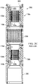
- FIG 3A shows an elevation view of an ACD-type annular sealing system 300 for purposes of illustration only.
- ACD-type annular sealing system 300 may include an upper annular packer system 310a and a lower annular packer system 310b as discussed in more detail herein.
- a lubrication injection port 320 may be disposed between upper annular packer system 310a and lower annular packer system 310b, configured to inject lubrication fluid (not shown) into the lubrication chamber (not independently illustrated) formed there between.
- Figure 3B shows a cross-sectional view of the ACD-type annular sealing system 300.
- ACD-type annular sealing system 300 may include a central lumen 350 that extends through the longitudinal length of annular sealing system 300 having an inner diameter suitable to receive the dual seal sleeve ( e.g ., 200 of Figure 2 ) or other configuration of the upper sealing element 100a and the lower sealing element 100b.
- the dual seal sleeve e.g ., 200 of Figure 2
- the dual seal sleeve may be disposed within annular sealing system 300 and secured in place with a plurality of upper locking dogs 340a and a plurality of lower locking dogs 340b that extend radially inward.
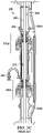
- Figure 3C shows a cross-sectional view of the ACD-type annular sealing system 300 with dual seal sleeve 200 disposed within the central lumen 350 of annular sealing system 300 and operatively positioned within upper annular packer system 310a and lower annular packer system 310b, with drill pipe 330 disposed through central lumen 270 that extends through an inner diameter of dual seal sleeve 200.
- sealing elements 100a and 100b of dual seal sleeve 200 are shown disengaged and do not make contact with drill pipe 330 or seal the annulus surrounding drill pipe 330 .
- FIG 4A shows a partial cross-sectional view of an annular packer system 310 of an ACD-type annular sealing system ( e.g ., 300 of Figure 3 ) in a disengaged state.
- Annular packer system 310 may include a piston-actuated (not shown) annular packer 420 disposed within a radiused housing 410 .
- Annular packer 420 may comprise an elastomer or rubber body with a plurality of fingers or protrusions 430 that are configured to travel within housing 410 when actuated.
- Sealing element 100 includes a central lumen 270 through which drill pipe 330 may pass therethrough.
- Figure 4B shows a partial cross-sectional view of the annular packer system 310 of the ACD-type annular sealing system ( e.g ., 300 of Figure 3 ) in an engaged state.
- a piston (not shown) causes the elastomer or rubber portion of packer 420 to travel within housing 410 such that packer 420 and fingers 430 come into contact with sealing element 100.
- sealing element 100 squeezes drill pipe 330, such that seal insert 120 and buffer material 130 come into contact with a circumference of drill pipe 330 resulting in a pressure tight interference fit surrounding drill pipe 330 .
- sealing element 100 remains stationary while drill pipe 330 rotates.
- Figure 5A shows a partial cross-sectional view of an ACD-type annular sealing system (e.g., 300 of Figure 3 ) with dual seal sleeve 200 and drill pipe 330 disposed therein, where upper annular packer system 310a and lower annular packer system 310b are in a disengaged state.
- the ACD-type annular sealing system e.g., 300 of Figure 3
- upper annular packer system 310a and lower annular packer system 310b are disengaged, upper annular packer 420a and lower annular packer 420b are disengaged and upper sealing element 100a and lower sealing element 100b are relaxed such that the annulus surrounding drill pipe 330 is unsealed.
- Figure 5B shows a partial cross-sectional view of the ACD-type annular sealing system (e.g., 300 of Figure 3 ) with dual seal sleeve 200 and drill pipe 330 disposed therein, where upper annular packer system 310a and lower annular packer system 310b are in an engaged state.
- upper annular packer system 310a and lower annular packer system 310b may be driven independent of one another.
- upper annular packer system 310a When upper annular packer system 310a is engaged, a hydraulically actuated piston 510a travels causing the elastomer or rubber portion of upper annular packer 420a to travel within upper radiused housing 410a.
- upper annular packer 420a When sufficiently engaged, upper annular packer 420a causes upper sealing element 100a to make contact, and form an interference fit with, drill pipe 330. Specifically, the upper seal insert 120a and upper buffer material 130a make contact and form an interference fit with a circumference of drill pipe 330 .
- lower annular packer system 310b When lower annular packer system 310b is engaged, a hydraulically actuated piston 510b travels causing the elastomer or rubber portion of lower annular packer 420b to travel within lower radiused housing 410b .
- lower annular packer 420b When sufficiently engaged, lower annular packer 420b causes lower sealing element 100b to make contact, and form an interference fit with, drill pipe 330 . Specifically, lower seal insert 120b and lower buffer material 130b make contact and form an interference fit with a circumference of drill pipe 330.
- Figure 5C shows a partial cross-sectional view of the ACD-type annular sealing system ( e.g., 300 of Figure 3 ) with dual seal sleeve 200 and drill pipe 330 disposed therein, where upper annular packer system 310a and lower annular packer system 310b are in an engaged state and lubrication is injected into lubrication chamber 550 via a lubrication injection port 320 .
- the pressure of lubrication chamber 550 may be maintained just above wellbore pressure by injecting a lubrication fluid 530 that may be comprised of, for example, active drilling mud, into the cavity (not independently illustrated).
- the hydraulic closing pressures (not shown) of upper annular packer system 310a and lower annular packer system 310b of the ACD-type annular sealing system ( e.g ., 300 of Figure 3 ), that are configured to engage upper sealing element 100a and lower sealing element 100b respectively, may be adjusted independently to maintain the desired pressure within lubrication chamber 550 .
- Lubrication fluid 530 cools and lubricates upper sealing element 100a and lower sealing element 100b .
- the injected lubrication fluid 530 that lubricates lower sealing element 100b may eventually work its way below lower sealing element 100b and join the return flow of fluids (not shown) to the choke manifold (not shown) disposed on the surface (not shown).
- the lubrication fluid 530 that lubricates upper sealing element 100a may be collected in the trip tank (not shown).
- the hydraulic closing pressures (not shown) of upper annular packer system 310a and lower annular packer system 310b of the ACD-type annular sealing system may be actively and independently adjusted to maintain the annular seal (not independently illustrated).
- an active control system may initialize the wellbore seal by engaging upper annular packer 420a and lower annular packer 420b to engage upper sealing element 100a and lower sealing element 100b.
- the active control system may inject hydraulic power fluid into upper closing chamber 540a and lower closing chamber 540b of upper annular packer system 310a and lower annular packer system 310b respectively and maintain closing pressures for each at the required level to maintain the annular seal.
- the amount of closing pressure applied to closing chamber 540 directly affects the amount of closing force acting on its respective sealing element 100 to seal the annulus.
- an optimal closing force may be applied to the sealing elements 100 to ensure a tight seal during critical events and extend the seal life during less intensive operations.
- the active control system (not shown), enables the ACD-type annular sealing system (e.g ., 300 of Figure 3 ) to hold wellbore pressure up to the static pressure rating of the system, such as, for example, approximately 2,000 pounds per square inch (“psi”) (13.8 MPa) when the drill string is not rotating.
- Figure 6A shows a cross-sectional view of a sealing element 100 of an ACD-type annular sealing system ( e.g ., 300 of Figure 3 ) in a new and unworn state in accordance with one or more embodiments of the present invention.
- Seal insert 120 and buffer material 130 are in a substantially new condition such that, when engaged, seal insert 120 and buffer material 130 make contact, and form an interference fit with, the drill pipe ( e.g ., 330 of Figure 5 ).
- Figure 6B shows a cross-sectional view of sealing element 100 of the ACD-type annular sealing system ( e.g ., 300 of Figure 3 ) in a partially worn state in accordance with one or more embodiments of the present invention.
- seal insert 120 and buffer material 130 are partially worn such that the shape of the central lumen 610 is bulbous. Consequently, because of the partially worn state of sealing element 100, the annular packer system ( e.g ., 310 of Figure 3 ) may require more hydraulic actuation, to cause the worn sealing element 100 to make sufficient closing contact with the drill pipe ( e.g ., 330 of Figure 5 ) to maintain the annular seal.
- the annular packer system e.g ., 310 of Figure 3
- the drill pipe e.g ., 330 of Figure 5
- Figure 6C shows a cross-sectional view of sealing element 100 of the ACD-type annular sealing system (e.g ., 300 of Figure 3 ) in a substantially worn state in accordance with one or more embodiments of the present invention.
- the annular packer system e.g. , 310 of Figure 3
- the annular packer system may require even more hydraulic actuation, to cause the substantially worn sealing element 100 to make sufficient closing contact with the drill pipe ( e.g. , 330 of Figure 5 ) to maintain the annular seal.
- Figure 6D shows a cross-sectional view of sealing element 100 of the ACD-type annular sealing system ( e.g ., 300 of Figure 3 ) in a fully worn state in accordance with one or more embodiments of the present invention.
- substantially worn sealing element 100 causes further wear to seal insert 120 and buffer material 130 such that a substantial portion of seal insert 120 is fully worn away and the central lumen is even more bulbous and consists primarily of buffer material 130 .
- the annular packer system (e.g ., 310 of Figure 3 ) may require even more hydraulic actuation, if even possible at all, to cause the fully worn sealing element 100 to make sufficient closing contact with the drill pipe ( e.g., 330 of Figure 5 ) to maintain the annular seal.
- buffer material 130 must be relied upon to make the closing contact with the drill pipe ( e.g ., 330 of Figure 5 ) in an attempt to maintain the annular seal.
- buffer material 130 is typically composed of polyurethane and is not wear resistant. While buffer material 130 wears rather quickly with rotation, it likely has a functional life on the order of magnitude of hours that allows the operator to plan replacement of the sealing element 100 at an opportune time.
- mud weight is the primary variable used to maintain the correct downhole pressure profile.
- the mud weight gradient must be both greater than the pore pressure gradient to prevent an influx under static conditions and less than the fracture pressure gradient to prevent fracturing the formation under dynamic conditions.
- An excursion of wellbore pressure below the pore pressure may result in an influx of formation fluids into the wellbore.
- exceeding the fracture pressure in one formation may decrease the annular fluid level, resulting in an influx from an offset formation.
- changes to the well pressure profile are made by circulating a new mud density, sometimes requiring hours to completely take effect. As the well progresses deeper, the contributions of dynamic pressures increase. Often, this results in smaller drilling margins and an increased risk of an influx near the end of a hole section.
- the deepwater and ultra-deepwater environments present their own unique sets of challenges. Due to the relatively high cost of drilling in deep waters, operators must seek out the most productive wells possible, which typically means drilling in formations with high permeability and porosity. In such formations, maintenance of downhole pressure is critical as a slight drawdown pressure can invite many barrels of formation fluids into the wellbore in a very short amount of time. Detection of kicks can also be more challenging in deep waters. Pit volumizing methods that are reliable on land are less effective when the drilling rig is pitching and rolling in the waves, meaning that significant volumes of formation fluids may enter the well before detection. In the event gas accumulates in the riser above the subsea BOP, a deepwater drilling rig may be forced to divert wellbore fluids overboard to protect the rig and crew from uncontrolled gas expansion.
- ASBP-MPD techniques provide a greater level of control over the drilling process compared to conventional drilling practices.
- variable annular surface pressure offsets the dynamic pressure lost during connections.
- the surface pressure and flow rate may be used as a feedback mechanism from the well, indicating the well state.
- ASBP-MPD a lighter mud weight is allowable, enabling drilling in narrower drilling margins. If losses are anticipated, the rig may drill ahead with back pressure greater than atmospheric pressure to allow downward pressure adjustment.
- flow occurs within a defined volume and may be driven through advanced flow meters, allowing the control system to analyze rate changes in addition to changes in volume accumulations, reducing the time to detect kicks.
- the MPD system may increase the annular pressure, potentially stopping the influx. Variations in the surface pressure affect the downhole pressure as early as the pressure front arrives, reducing the time for deliberate changes to take effect from hours to minutes or seconds. This merging of reduced time to detection and better response actions results in smaller total influx volumes. Smaller influx volumes contain less energy than larger influx volumes, reducing the possibility of damaging weaker formations during kick circulation.
- an ACD-type annular sealing system tailored for deepwater and ultra-deepwater MPD applications may use dual American Petroleum Institute ("API") 16A annular packer systems to actuate a non-rotating dual API 16RCD seal sleeve assembly without the use of a bearing assembly.
- An active control system may be used to adjust control parameters on each sealing element independently of one another, allowing the closing force to be optimized for the current drilling parameters. As a sealing element wears, the active control system maintains seal integrity by keeping contact between the sealing element and the drillpipe.
- the active control system enables monitoring of the parameters for controlling the seal, facilitating direct monitoring of the sealing element condition. Condition monitoring allows the drilling rig to proactively plan future operations and reduce the occurrence of downtime for reactive maintenance.
- seal condition monitoring may be implemented through analysis of one or more control parameters, measured values, and modeled values.
- Sealing element wear may be induced only when the drill string is in motion. As the sealing elements accumulate rotating and stripping hours, as noted above, the seal inserts are gradually worn. While the seal insert is intact, the material properties of the seal insert and the buffer material affect the closing pressure required to create the annular seal. When the seal inserts are worn, only the material properties of the buffer material affect the closing pressure required to create a seal.
- An alert may signify that one or more seal inserts are worn but does not imply a failure of the ACD-type annular sealing system to hold wellbore pressure or a failure of one or more sealing elements themselves.
- the drill pipe tool joint diameter drifts through the sealing element, which demonstrates that the active control device supplies the closing pressure necessary to create the annular seal, not the geometry of the sealing element.
- wearing of the seal insert only implies that the available rotating life is limited.
- the observance of the seal wear alert serves as a good point to strip to a safe stopping point and start preparing the well for seal sleeve retrieval and replacement operation.
- an ACD-type annular sealing system (e.g ., 300 of Figure 3 ) was used to determine the optimal closing pressure to apply as a function of wellbore pressure and drill pipe rotation rate.
- the drill mode tests were conducted holding the drill ahead ASBP at 250 psi (1.7 MPa) with a drill pipe rotation rate of 160 revolutions per minute (“rpm").
- Figure 7A shows the optimal closing pressure range for the upper annular packer system ( e.g. , 310a of Figure 3 ) in accordance with one or more embodiments of the present invention.
- Figure 7B shows the optimal closing pressure range for the lower annular packer system ( e.g ., 310b of Figure 3 ) in accordance with one or more embodiments of the present invention.
- the upper annular packer system ( e.g ., 310a of Figure 3 ) and the lower annular packer system ( e.g ., 310b of Figure 3 ) require different closing pressures because of the differential pressures at which each sealing element ( i.e., 100a versus 100b ) hold the seal are different.
- the lubrication chamber (e.g., 550 of Figure 5C ) pressure, the pressure in the chamber in between the upper sealing element ( e.g ., 100a of Figure 2 ) and the lower sealing element ( e.g., 100b of Figure 2 ) may be maintained at a pressure somewhat higher than the wellbore pressure to ensure containment of wellbore fluids below the lower sealing element ( e.g ., 100b of Figure 2 ).
- the differential pressure on the lower sealing element may be approximately 50 psi (0,34 MPa) above wellbore pressure, ensuring that any leaked fluid is clean mud leaking down from the lubrication chamber ( e.g., 550 of Figure 5C ), rather than wellbore fluids leaking up from the well.
- the differential pressure on the upper sealing element e.g ., 100a of Figure 2
- the differential pressure on the upper sealing element is the difference between the lubrication chamber ( e.g., 550 of Figure 5C ) pressure and the atmosphere.
- the state of the upper sealing element seal insert may be determined by decreased lubrication pressure or increased closing pressure required to maintain the seal.
- the drilling rig may continue operations while holding pressure for an additional amount of time until the lower sealing element requires replacement.
- the amount of time that the rig may operate after detection of a worn seal insert may vary but can be determined as a function of the drilling parameters in effect.
- the signature may be developed through finite element analysis, empirical data, or combinations thereof.
- Figure 8 shows the relationship between the closing pressure and the closing chamber volume of an annular packer system ( e.g., 310 of Figure 3 ) in accordance with one or more embodiments of the present invention.
- the closing pressure and closing chamber volume are interrelated hydraulic control system variables.
- a hydraulic power unit provides hydraulic fluid injection into the closing chamber of the annular packer system, thereby increasing closing pressure causing one or more pistons (not shown) of the annular packer system to close on the sealing element when sufficient closing pressure is applied.
- the sealing element deforms and bows inward radially toward the drill pipe, where the seal insert makes contact with the drill pipe (when the seal insert is not entirely worn).
- the inward bow of the sealing element results in additional piston displacement for a given closing pressure.
- the closing pressure required to create the seal is a function of the wellbore pressure and the sealing element material properties.
- the geometry of the sealing element changes (i.e ., as shown in Figures 6A through 6D ) from the slow wear of sealing element material volume, primarily of the seal insert, but also the buffer material.
- rotation of the drill string within the non-rotating sealing element reduces the wall thickness of the seal insert.
- the reduction in seal insert thickness reduces the volume of the sealing element.
- the reduction in volume of the sealing element volume is offset by increasing the closing chamber volume for a given closing pressure and wellbore pressure.
- a sequence for condition monitoring may be formed when a closing pressure and closing chamber volume necessary to maintain the annular seal at a given wellbore pressure is applied to indicate the amount of sealing element material remaining.
- the relationship between the closing pressure, the closing chamber volume, and the wear state of the sealing element, specifically the seal insert, may be determined as shown in Figure 8 .
- a method of seal condition monitoring for an ACD-type annular sealing system may include engaging an upper annular packer system to engage an upper sealing element to form an upper interference fit that seals an annulus surrounding a drill pipe.
- the upper annular packer system may include a piston-actuated upper annular packer that is configured to travel within the spherical housing of the upper annular packer system, exerting a closing force on the upper sealing element. Because the upper sealing element is composed of a seal insert co-molded with a buffer material, the closing force causes the upper sealing element to bow inward radially, forming the interference fit with the drill pipe. As noted above, the upper sealing element remains stationary as the drill pipe rotates.
- An active control system may determine the upper closing pressure required for the upper annular packer of the upper annular packer system to sufficiently close on the upper sealing element to form the upper interference fit. The determination may be made based on the ability of the lubrication chamber to hold pressure and the direction that lubrication fluids flow.
- the active control system may actively adjust the upper closing pressure to maintain the upper interference fit.
- actively means on an ongoing basis during drilling operations and includes any adjustment period including continuous real-time adjustment or adjustment at predetermined intervals of time.
- an alert may be provided to an operator via a display of the active control system indicating that the upper sealing element is worn.
- the active control system may take actions such as, for example, scheduling or halting drilling operations.
- the delta in closing pressure the amount and period of which may vary based on an application or design, signifies that the seal insert has worn and that the interference fit may be maintained by the buffer material alone, which is not wear resistant and will wear rather quickly.
- the delta detected doesn't necessarily mean the sealing element has failed, just that it doesn't have much longer until it does fail.
- the period that drilling may be extended under such circumstances is typically on the order of magnitude of hours.
- the predetermined amount and the predetermined period of time may be determined in advance by modeling, measurement, or analysis of empirical results for a given annular sealing system and sealing element.
- the method may include engaging a lower annular packer system to engage a lower sealing element to form a lower interference fit that seals the annulus surrounding the drill pipe (below the seal created by the upper sealing element).
- the lower annular packer system may include a piston-actuated lower annular packer that is configured to travel within the spherical housing of the lower annular packer system, exerting a closing force on the lower sealing element. Because the lower sealing element is composed of a seal insert co-molded with a buffer material, the closing force causes the lower sealing element to bow inward radially, forming the interference fit with the drill pipe. As noted above, the lower sealing element remains stationary as the drill pipe rotates.
- the active control system may determine the lower closing pressure required for the lower annular packer of the lower annular packer system to sufficiently close on the lower sealing element to form the lower interference fit. The determination may be made based on the ability of the lubrication chamber to hold pressure and the direction that lubrication fluids flow.
- the active control system may actively adjust the lower closing pressure to maintain the lower interference fit. In certain embodiments, if a change in the lower closing pressure required to maintain the lower interference fit exceeds a predetermined amount over a predetermined period of time, an alert may be provided to the operator via a display of the active control system indicating that the lower sealing element is worn. In other embodiments, if a change in the lower closing pressure required to maintain the lower interference fit exceeds a predetermined amount over a predetermined period of time, the active control system may take actions such as, for example, scheduling or halting drilling operations.
- a lubrication injection port may inject lubrication fluids into the lubrication chamber and a relief valve may be used to relieve pressure in the lubrication chamber should it be required.
- the lubrication chamber pressure is maintained at a pressure somewhat higher than the wellbore pressure to ensure that leaks of injected lubrication fluid leak down.
- a method of seal condition monitoring for an ACD-type annular sealing system may include stopping drilling operations, if any, and engaging a drill string isolation tool, or equivalent thereof, to seal the annulus surrounding a drill pipe.
- the method may include disengaging the upper annular packer system to disengage the upper sealing element to unseal the annulus surrounding the drill pipe and disengaging the lower annular packer system to disengage the lower sealing element to unseal the annulus surrounding the drill pipe.
- the hydraulic power unit may be configured to provide hydraulic power to one or more upper actuating pistons of an upper annular packer system. Then the upper annular packer system may be engaged to engage the upper sealing element to close on the drill pipe up to a predetermined upper calibration pressure.
- the predetermined upper calibration pressure may be 2,000 psi (13.8 MPa).
- the predetermined upper calibration pressure may vary based on an application or design in accordance with one or more embodiments of the present invention.
- the predetermined upper calibration pressure may represent the maximum amount of upper closing pressure capable of being applied.
- the upper flow meter may be monitored to determine an upper closing chamber volume for a predetermined period of time.
- the predetermined period of time may include any period up to and including the entire run time after calibration.
- the condition of the upper sealing element may be determined based on a predetermined relationship, such as that shown in, for example, Figure 8 , between the upper closing chamber volume and an extent to which the upper sealing element is worn.
- the extent may be determined by empirical data, statistical analysis, or modeling.
- An active control system may provide the operator with an indication of the extent to which the upper sealing element is worn based on the determined condition, such indication may be displayed on a display of the active controls system.
- a lower flow meter of the hydraulic power unit may be tared.
- the hydraulic power unit may be configured to provide hydraulic power to one or more upper actuating pistons of a lower annular packer system. Then the lower annular packer system may be engaged to engage the lower sealing element to close on the drill pipe up to a predetermined lower calibration pressure.
- the predetermined lower calibration pressure may be 2,000 psi (13.8 MPa).
- the predetermined lower calibration pressure may vary based on an application or design in accordance with one or more embodiments of the present invention.
- the predetermined upper calibration pressure may represent the maximum amount of upper closing pressure capable of being applied.
- the lower flow meter may be monitored to determine an lower closing chamber volume for a predetermined period of time.
- the predetermined period of time may include any period up to and including the entire run time after calibration.
- the condition of the lower sealing element may be determined based on a predetermined relationship, such as that shown in, for example, Figure 8 , between the lower closing chamber volume and an extent to which the lower sealing element is worn.
- the extent may be determined by empirical data, statistical analysis, or modeling.
- the active control system may provide the operator with an indication of the extent to which the lower sealing element is worn based on the determined condition, such indication may be displayed on a display of the active controls system.
- a method of seal condition monitoring for an ACD-type annular sealing system may include generating modeled data including one or more of a modeled upper closing pressure of an upper annular packer of an upper annular packer system, a modeled wellbore pressure, and a modeled lubrication chamber pressure of the annular sealing system for anticipated drilling operations and conditions.
- Measured data may be input including one or more of a measured upper closing pressure of the upper annular packer of the upper annular packer system, a measured wellbore pressure, and a measured lubrication chamber pressure of the annular sealing system for drilling operations and conditions.
- the measured data may be compared with the modeled data to determine a condition of the upper sealing element.
- the active control system may provide the operator with the condition of the upper sealing element such that appropriate action may be taken.
- the condition may be provided via a display of the active control system.
- the active control system may take appropriate action based on the condition of the upper sealing element.
- modeled data may be generated including one or more of a modeled lower closing pressure of a lower annular packer of an lower annular packer system, a modeled wellbore pressure, and a modeled lubrication chamber pressure of the annular sealing system for anticipated drilling operations and conditions.
- Measured data may be input including one or more of a measured lower closing pressure of the lower annular packer of the lower annular packer system, a measured wellbore pressure, and a measured lubrication chamber pressure of the annular sealing system for drilling operations and conditions.
- the measured data may be compared with the modeled data to determine a condition of the lower sealing element.
- the active control system may provide the operator with the condition of the lower sealing element such that appropriate action may be taken.
- the condition may be provided via a display of the active control system.
- the active control system may take appropriate action based on the condition of the lower sealing element.
- a system for seal condition monitoring may include an ACD-type annular sealing system and an active control system.
- the ACD-type annular sealing system may include an upper annular packer system having a piston-actuated upper annular packer configured to engage an upper sealing element to close on a drill pipe to form an upper interference fit that seals the annulus surrounding the drill pipe.
- the lower annular packer system may include a piston-actuated lower annular packer configured to engage a lower sealing element to close on the drill pipe to form a lower interference fit that seals the annulus surrounding the drill pipe.
- a lubrication chamber may be disposed in between the upper annular packer system and the lower annular packer system that includes a lubrication injection port and a pressure relief valve.
- the active control system may provide the operator with one or more of a condition of the upper sealing element and the lower sealing element or an indication of the extent to which the upper sealing element and the lower sealing element are worn.
- the system may include a hydraulic power unit that includes an upper annular packer hydraulic power line and a lower annular packer hydraulic power line.
- the upper annular packer hydraulic power line provides hydraulic power to actuate the upper annular packer piston and the lower annular packer hydraulic power line provides hydraulic power to actuate the lower annular packer piston.
- the system may include an upper flow meter may be configured to measure a hydraulic injection fluid flow in the upper annular packer hydraulic power line and a lower flow meter configured to measure the hydraulic injection fluid flow in the lower annular packer hydraulic power line.
- the system may include a wellbore pressure measurement device configured to measure wellbore pressure. The active control system may determine the lubrication chamber pressure, the upper annular packer closing pressure, and the lower annular packer closing pressure.
- Figure 9 shows an active control system 900 in accordance with one or more embodiments of the present invention. accordance with one or more embodiments of the present invention.
- Active control system 900 may be used to control all aspects of the operation of the ACD-type annular sealing system (e.g. , 300 of Figure 3 ) including, for example, one or more of the upper closing pressure to the upper annular packer system, the lower closing pressure to the lower annular packer system, and the lubrication chamber pressure of the lubrication chamber. Active control system 900 may control such things through control of the hydraulic power unit (not shown), the lubrication fluid injection flow rate, and the lubrication chamber ( e.g. , 550 of Figure 5C ) relief valve.
- the hydraulic power unit not shown
- the lubrication fluid injection flow rate e.g. , 550 of Figure 5C
- Active control system 900 may also monitor measured properties including, for example, one or more of measured flow rates of hydraulic power fluid to the upper annular packer system, measured flow rates of hydraulic power fluid to the lower annular packer system, measured wellbore pressure, measured flow rates of injected lubrication fluid, measured lubrication chamber pressure. Active control system 900 may also perform all modeling, correlation, comparison, and data analysis used as part of a system for seal condition monitoring.
- Active control system 900 may include one or more processor cores 910 disposed on one or more printed circuit boards (not shown). Each of the one or more processor cores 910 may be a single-core processor (not independently illustrated) or a multi-core processor (not independently illustrated). Multi-core processors typically include a plurality of processor cores disposed on the same physical die (not shown) or a plurality of processor cores disposed on multiple die (not shown) that are collectively disposed within the same mechanical package. Active control system 900 may also include various core logic components such as, for example, a north, or host, bridge device 915 and a south, or input/output ("IO"), bridge device 920.
- IO input/output
- North bridge 915 may include one or more processor interface(s), memory interface(s), graphics interface(s), high speed IO interface(s) (not shown), and south bridge interface(s).
- South bridge 920 may include one or more IO interface(s).
- processor cores 910, north bridge 915, and south bridge 920, or various subsets or combinations of functions or features thereof, may be integrated, in whole or in part, or distributed among various discrete devices, in a way that may vary based on an application, design, or form factor in accordance with one or more embodiments of the present invention.
- Active control system 900 may include one or more IO devices such as, for example, a display device 925, system memory 930, optional keyboard 935, optional mouse 940, and/or an optional human-computer interface 945. Depending on the application or design of active control system 900, the one or more IO devices may or may not be integrated.
- Display device 925 may be a touch screen that includes a touch sensor (not independently illustrated) configured to sense touch. For example, a user may interact directly with objects depicted on display device 925 by touch or gestures that are sensed by the touch sensor and treated as input by active control system 900 .
- Active control system 900 may include one or more local storage devices 950 .
- Local storage device 950 may be a solid-state memory device, a solid-state memory device array, a hard disk drive, a hard disk drive array, or any other non-transitory computer readable medium.
- Active control system 900 may include one or more network interface devices 955 that provide one or more network interfaces.
- the network interface may be Ethernet, Wi-Fi, Bluetooth, WiMAX, Fibre Channel, or any other network interface suitable to facilitate networked communications.
- active control system 900 may be a cloud-based server, a server, a workstation, a desktop, a laptop, a netbook, a tablet, a smartphone, a mobile device, and/or any other type of computing system in accordance with one or more embodiments of the present invention.
- active control system 900 may be any other type or kind of system based on programmable logic controllers ("PLC"), programmable logic devices (“PLD”), or any other type or kind of system, including combinations thereof, capable of inputting data, performing calculations, and outputting control signals that manipulate a smart choke manifold.
- PLC programmable logic controllers
- PLD programmable logic devices
- the functions performed by active control system 900 may be incorporated into one or more pre-existing computer systems disposed on the drilling rig and instrumented in a similar manner.
Claims (8)
- Procédé de surveillance de l'état des joints pour un système d'étanchéité annulaire (300) comprenant :l'engagement d'un système de packer annulaire supérieur (310a) pour engager un élément d'étanchéité supérieur (100a) afin de former un ajustement serré supérieur qui rend étanche un espace annulaire entourant une tige de forage (330);déterminer une pression de fermeture supérieure requise pour qu'un packer annulaire supérieur (420a) du système de packer annulaire supérieur (310a) se ferme suffisamment sur l'élément d'étanchéité supérieur (100a) pour former l'ajustement d'interférence supérieur;pendant les opérations de forage, ajuster activement la pression de fermeture supérieure pour maintenir l'ajustement serré supérieur; etsi un changement de la pression de fermeture supérieure nécessaire pour maintenir l'ajustement d'interférence supérieur dépasse une quantité prédéterminée sur une période de temps prédéterminée, fournir à un opérateur une alerte indiquant que l'élément d'étanchéité supérieur (100a) est usé,dans lequel l'élément d'étanchéité supérieur (100a) comprend un insert d'étanchéité supérieur (120a) co-moulé avec un matériau tampon supérieur (130a).
- Procédé de surveillance de l'état du joint selon la revendication 1, comprenant en outre :l'engagement d'un système de packer annulaire inférieur (310b) pour engager un élément d'étanchéité inférieur (100b) afin de former un ajustement serré inférieur qui ferme hermétiquement un espace annulaire entourant la tige de forage (330);déterminer une pression de fermeture inférieure requise pour qu'un packer annulaire inférieur (420b) du système de packer annulaire inférieur (310b) se ferme de manière suffisante sur l'élément d'étanchéité inférieur (100b) pour former l'ajustement d'interférence inférieur;pendant les opérations de forage, ajuster activement la pression de fermeture inférieure pour maintenir l'ajustement serré inférieur; etsi un changement de la pression de fermeture inférieure nécessaire pour maintenir l'ajustement serré inférieur dépasse une quantité prédéterminée sur une période de temps prédéterminée, fournir à l'opérateur une alerte indiquant que l'élément d'étanchéité inférieur (100b) est usé.
- Procédé de surveillance de l'état des joints pour un système d'étanchéité annulaire (300) comprenant:le tarage d'un débitmètre supérieur d'une unité de puissance hydraulique configurée pour fournir une puissance hydraulique à un ou plusieurs pistons d'actionnement supérieurs d'un système de packer annulaire supérieur (310a);engager le système de packer annulaire supérieur (310a) pour engager un élément d'étanchéité supérieur (100a) pour se fermer sur un tube de forage (330) jusqu'à une pression d'étalonnage supérieure prédéterminée;surveiller le débitmètre supérieur pour déterminer un volume de chambre de fermeture supérieure pendant une période de temps prédéterminée ;déterminer un état de l'élément d'étanchéité supérieur (100a) sur la base d'une relation prédéterminée entre le volume de la chambre de fermeture supérieure et une mesure dans laquelle l'élément d'étanchéité supérieur (100a) est usé; etfournir à un opérateur une indication de la mesure dans laquelle l'élément d'étanchéité supérieur (100a) est usé sur la base de la condition déterminée,dans lequel l'élément d'étanchéité supérieur (100a) comprend un insert d'étanchéité supérieur (120a) co-moulé avec un matériau tampon supérieur (130a).
- Procédé de surveillance de l'état du joint selon la revendication 3, comprenant en outre :le tarage d'un débitmètre inférieur de l'unité de puissance hydraulique configurée pour fournir une puissance hydraulique à un ou plusieurs pistons d'actionnement inférieurs du système de packer annulaire inférieur (310b);l'engagement du système de packer annulaire inférieur (310b) pour engager un élément d'étanchéité inférieur (100b) pour se fermer sur le tube de forage (330) jusqu'à une pression de calibrage inférieure prédéterminée;surveiller le débitmètre inférieur pour déterminer un volume de chambre de fermeture inférieur pendant la période de temps prédéterminée ;déterminer un état de l'élément d'étanchéité inférieur (100b) sur la base d'une relation prédéterminée entre le volume de la chambre de fermeture inférieure et une mesure dans laquelle l'élément d'étanchéité inférieur (100b) est usé; etfournir à l'opérateur une indication de la mesure dans laquelle l'élément d'étanchéité inférieur (100b) est usé sur la base de la condition déterminée.
- Procédé de surveillance de l'état du joint selon la revendication 3, comprenant en outre:l'arrêt des opérations de forage;l'engagement d'un outil d'isolation de train de tiges de forage pour sceller un espace annulaire entourant la tige de forage (330);le désengagement du système de packer annulaire supérieur (310a) pour désengager l'élément d'étanchéité supérieur (100a) pour desceller l'espace annulaire entourant le tube de forage (330); etdésengager le système de packer annulaire inférieur (310b) pour désengager l'élément d'étanchéité inférieur (100b) pour desceller l'espace annulaire entourant la tige de forage (330).
- Procédé de surveillance de l'état des joints selon la revendication 1 ou 3, comprenant en outre:
le maintien d'une pression de la chambre de lubrification (550) supérieure à une pression du puits de forage. - Procédé de surveillance de l'état des joints selon la revendication 1 ou 3,dans lequel l'insert d'étanchéité supérieur (100a) comprend en particulier du polytétrafluoroéthylène, du polyéthylène de poids moléculaire très élevé, ou un autre matériau à base de polymère oudans lequel le matériau tampon supérieur (130a) comprend en particulier du polyuréthane, du nitrile, du caoutchouc acrylonitrile-butadiène, du caoutchouc acrylonitrile-butadiène hydrogéné, ou un autre matériau élastomère oudans lequel l'insert d'étanchéité supérieur (100a) comprend en particulier un motif en nid d'abeille ou matriciel qui fournit une résistance à l'usure lorsque le contact est fait avec la tige de forage (330) lorsqu'elle tourne.
- Procédé de surveillance de l'état des joints selon la revendication 2 ou 4,dans lequel l'élément d'étanchéité inférieur (100b) comprend un insert d'étanchéité inférieur (100b) co-moulé avec un matériau tampon inférieur (130b),dans lequel l'insert d'étanchéité inférieur (100b) comprend en particulier du polytétrafluoroéthylène, du polyéthylène de poids moléculaire très élevé, ou un autre matériau à base de polymère oudans lequel le matériau tampon inférieur (130b) comprend en particulier du polyuréthane, du nitrile, du caoutchouc acrylonitrile-butadiène, du caoutchouc acrylonitrile-butadiène hydrogéné, ou un autre matériau élastomère oudans lequel l'insert de joint inférieur (100b) comprend en particulier un motif en nid d'abeille ou matriciel qui fournit une résistance à l'usure lorsque le contact est fait avec la tige de forage (330) lorsqu'elle tourne.
Applications Claiming Priority (3)
| Application Number | Priority Date | Filing Date | Title |
|---|---|---|---|
| US201762597601P | 2017-12-12 | 2017-12-12 | |
| US201862747086P | 2018-10-17 | 2018-10-17 | |
| PCT/US2018/064839 WO2019118394A1 (fr) | 2017-12-12 | 2018-12-11 | Surveillance d'état de joint d'étanchéité |
Publications (3)
| Publication Number | Publication Date |
|---|---|
| EP3701123A1 EP3701123A1 (fr) | 2020-09-02 |
| EP3701123A4 EP3701123A4 (fr) | 2021-07-28 |
| EP3701123B1 true EP3701123B1 (fr) | 2023-01-25 |
Family
ID=66819725
Family Applications (1)
| Application Number | Title | Priority Date | Filing Date |
|---|---|---|---|
| EP18888557.8A Active EP3701123B1 (fr) | 2017-12-12 | 2018-12-11 | Surveillance d'état de joint d'étanchéité |
Country Status (5)
| Country | Link |
|---|---|
| US (2) | US11306551B2 (fr) |
| EP (1) | EP3701123B1 (fr) |
| BR (1) | BR112020011247B1 (fr) |
| CA (1) | CA3084979A1 (fr) |
| WO (1) | WO2019118394A1 (fr) |
Families Citing this family (7)
| Publication number | Priority date | Publication date | Assignee | Title |
|---|---|---|---|---|
| BR112020011247B1 (pt) | 2017-12-12 | 2023-11-14 | Ameriforge Group Inc | Método para monitoramento de condição de vedação para um sistema de vedação anular |
| CA3116658A1 (fr) | 2018-10-19 | 2020-04-23 | Ameriforge Group Inc. | Systeme faisant etancheite annulaire et joint de colonne montante de forage a pression controlee integre |
| EP3874119B1 (fr) | 2018-11-02 | 2023-08-30 | Grant Prideco, Inc. | Systèmes d'étanchéité annulaires statiques et joints de colonne montante de forage à pression commandée intégrés pour environnements hostiles |
| US20200240265A1 (en) * | 2019-01-28 | 2020-07-30 | Saudi Arabian Oil Company | Straddle Packer Testing System |
| US11118421B2 (en) | 2020-01-14 | 2021-09-14 | Saudi Arabian Oil Company | Borehole sealing device |
| US11332987B2 (en) | 2020-05-11 | 2022-05-17 | Safekick Americas Llc | Safe dynamic handover between managed pressure drilling and well control |
| CN112343584A (zh) * | 2020-11-03 | 2021-02-09 | 中国石油天然气股份有限公司 | 一种用于水平井验管外窜流的压力工作筒及其验证方法 |
Family Cites Families (33)
| Publication number | Priority date | Publication date | Assignee | Title |
|---|---|---|---|---|
| US3561723A (en) | 1968-05-07 | 1971-02-09 | Edward T Cugini | Stripping and blow-out preventer device |
| US3955822A (en) | 1975-03-28 | 1976-05-11 | Dresser Industries, Inc. | Rod pump stuffing box control system |
| US7802635B2 (en) * | 2007-12-12 | 2010-09-28 | Smith International, Inc. | Dual stripper rubber cartridge with leak detection |
| US9347289B2 (en) * | 2008-12-16 | 2016-05-24 | Hydril USA Distribution LLC | Blowout preventer system having position and pressure sensing device and related methods |
| US8322432B2 (en) | 2009-01-15 | 2012-12-04 | Weatherford/Lamb, Inc. | Subsea internal riser rotating control device system and method |
| US9284811B2 (en) * | 2009-06-19 | 2016-03-15 | Schlumberger Technology Corporation | Universal rotating flow head having a modular lubricated bearing pack |
| US8347983B2 (en) | 2009-07-31 | 2013-01-08 | Weatherford/Lamb, Inc. | Drilling with a high pressure rotating control device |
| GB2489265B (en) * | 2011-03-23 | 2017-09-20 | Managed Pressure Operations | Blow out preventer |
| US8347982B2 (en) | 2010-04-16 | 2013-01-08 | Weatherford/Lamb, Inc. | System and method for managing heave pressure from a floating rig |
| EP2564017A1 (fr) | 2010-04-27 | 2013-03-06 | Geoservices Equipements | Boîte à garniture pour un puits de production de fluide, et ensemble de surface associé |
| US9428994B2 (en) * | 2010-07-01 | 2016-08-30 | National Oilwell Varco, L.P. | Blowout preventer monitor with trigger sensor and method of using same |
| US9310011B2 (en) | 2011-04-08 | 2016-04-12 | Axon Ep, Inc. | Fluid end manifolds and fluid end manifold assemblies |
| US10024310B2 (en) | 2011-04-28 | 2018-07-17 | Afglobal Corporation | Modular pump design |
| WO2013006963A1 (fr) | 2011-07-14 | 2013-01-17 | Michael Boyd | Dispositif rotatif de régulation d'écoulement à l'intérieur d'une colonne montante |
| US20130168579A1 (en) | 2011-12-29 | 2013-07-04 | Metal Industries Research & Development Centre | Fluid regulating valve |
| BR112015019224A2 (pt) | 2013-02-11 | 2017-07-18 | Schlumberger Technology Bv | aparelho, e método |
| KR101717870B1 (ko) * | 2013-02-21 | 2017-03-17 | 내셔널 오일웰 바르코 엘.피. | 분출 방지기 감시 시스템 및 그 사용 방법 |
| GB2520533B (en) * | 2013-11-22 | 2020-05-06 | Managed Pressure Operations | Pressure containment device |
| GB201401223D0 (en) * | 2014-01-24 | 2014-03-12 | Managed Pressure Operations | Sealing element wear indicator system |
| GB2525396B (en) * | 2014-04-22 | 2020-10-07 | Managed Pressure Operations | Method of operating a drilling system |
| US9500057B2 (en) | 2014-07-09 | 2016-11-22 | Saudi Arabia Oil Company | Apparatus and method for preventing tubing casing annulus pressure communication |
| MY183573A (en) | 2014-08-21 | 2021-02-26 | Halliburton Energy Services Inc | Rotating control device |
| US9725978B2 (en) | 2014-12-24 | 2017-08-08 | Cameron International Corporation | Telescoping joint packer assembly |
| WO2017044101A1 (fr) | 2015-09-10 | 2017-03-16 | Halliburton Energy Services, Inc. | Dispositif de commande de rotation intégré et système de manipulation de gaz pour un système de forage marin |
| BR112019026145A2 (pt) | 2017-06-12 | 2020-06-30 | Ameriforge Group Inc. | sistema de perfuração de gradiente duplo, gradiente duplo sem riser e gradiente duplo sem riser distribuído e método de perfuração de gradiente duplo |
| US10494877B2 (en) | 2017-08-16 | 2019-12-03 | Weatherford Technology Holdings, Llc | Subsea rotating control device apparatus having debris barrier |
| US10648259B2 (en) | 2017-10-19 | 2020-05-12 | Safekick Americas Llc | Method and system for controlled delivery of unknown fluids |
| BR112020011247B1 (pt) | 2017-12-12 | 2023-11-14 | Ameriforge Group Inc | Método para monitoramento de condição de vedação para um sistema de vedação anular |
| EP3788229B1 (fr) | 2018-05-02 | 2023-06-07 | Grant Prideco, Inc. | Dispositif de commande tournant amélioré pour plate-formes terrestres |
| EP3788230B1 (fr) | 2018-05-02 | 2023-06-07 | Grant Prideco, Inc. | Dispositif de commande tournant amélioré pour plate-formes auto-élévatrices |
| CA3116658A1 (fr) | 2018-10-19 | 2020-04-23 | Ameriforge Group Inc. | Systeme faisant etancheite annulaire et joint de colonne montante de forage a pression controlee integre |
| EP3874119B1 (fr) | 2018-11-02 | 2023-08-30 | Grant Prideco, Inc. | Systèmes d'étanchéité annulaires statiques et joints de colonne montante de forage à pression commandée intégrés pour environnements hostiles |
| WO2021150299A1 (fr) | 2020-01-20 | 2021-07-29 | Ameriforge Group Inc. | Joint de forage à pression contrôlée en eau profonde |
-
2018
- 2018-12-11 BR BR112020011247-0A patent/BR112020011247B1/pt active IP Right Grant
- 2018-12-11 EP EP18888557.8A patent/EP3701123B1/fr active Active
- 2018-12-11 WO PCT/US2018/064839 patent/WO2019118394A1/fr unknown
- 2018-12-11 CA CA3084979A patent/CA3084979A1/fr active Pending
-
2020
- 2020-06-09 US US16/896,625 patent/US11306551B2/en active Active
- 2020-06-09 US US16/896,612 patent/US11306550B2/en active Active
Also Published As
| Publication number | Publication date |
|---|---|
| US20200300051A1 (en) | 2020-09-24 |
| BR112020011247A2 (pt) | 2020-11-17 |
| BR112020011247B1 (pt) | 2023-11-14 |
| EP3701123A4 (fr) | 2021-07-28 |
| WO2019118394A1 (fr) | 2019-06-20 |
| US11306550B2 (en) | 2022-04-19 |
| CA3084979A1 (fr) | 2019-06-20 |
| US20200300052A1 (en) | 2020-09-24 |
| US11306551B2 (en) | 2022-04-19 |
| EP3701123A1 (fr) | 2020-09-02 |
Similar Documents
| Publication | Publication Date | Title |
|---|---|---|
| EP3701123B1 (fr) | Surveillance d'état de joint d'étanchéité | |
| US10036227B2 (en) | Pressure containment device | |
| US9500053B2 (en) | Drilling system and method of operating a drilling system | |
| US9080427B2 (en) | Seabed well influx control system | |
| US20170044857A1 (en) | Method of operating a drilling system | |
| EP2500510B1 (fr) | Détection d'afflux de fluide améliorée au cours du forage sous pression controlee | |
| US11466524B2 (en) | Closed-loop hydraulic drilling | |
| NO327281B1 (no) | Tetningsarrangement, samt tilhorende fremgangsmate | |
| EA039941B1 (ru) | Способ и система для управляемой доставки текучих сред неизвестного состава | |
| Toralde et al. | Riser gas risk mitigation with advanced flow detection and managed pressure drilling technologies in deepwater operations | |
| Guner | Simulation study of emerging well control methods for influxes caused by bottomhole pressure fluctuations during managed pressure drilling | |
| Johnson et al. | Real Time Condition Monitoring of the Wellbore Seal through Hydraulic Fluid Analysis Using an Active Wellbore Sealing System during Managed Pressure Drilling | |
| CA3207057A1 (fr) | Systemes, procedes et appareil de gestion amelioree de dispositifs actionnes hydrauliquement et systemes associes | |
| Johnson et al. | Delivering an Innovative Active MPD Wellbore Sealing System for Field Operations | |
| Prasodjo et al. | Internal Check Valve Installation to Eliminate Well Integrity Issue | |
| Mugharbil et al. | Wellhead and Valve Technology Principles, Problems and Practices | |
| Prieur | Control aspects of drilling high pressure wells | |
| Potter | Handling free gas in deep and ultra-deep water drilling risers: a technical review and safety case explanation. | |
| Montgomery et al. | Drilling Well Control Practices and Equipment Considerations for Deepwater Operations Plans |
Legal Events
| Date | Code | Title | Description |
|---|---|---|---|
| STAA | Information on the status of an ep patent application or granted ep patent |
Free format text: STATUS: THE INTERNATIONAL PUBLICATION HAS BEEN MADE |
|
| PUAI | Public reference made under article 153(3) epc to a published international application that has entered the european phase |
Free format text: ORIGINAL CODE: 0009012 |
|
| STAA | Information on the status of an ep patent application or granted ep patent |
Free format text: STATUS: REQUEST FOR EXAMINATION WAS MADE |
|
| 17P | Request for examination filed |
Effective date: 20200528 |
|
| AK | Designated contracting states |
Kind code of ref document: A1 Designated state(s): AL AT BE BG CH CY CZ DE DK EE ES FI FR GB GR HR HU IE IS IT LI LT LU LV MC MK MT NL NO PL PT RO RS SE SI SK SM TR |
|
| AX | Request for extension of the european patent |
Extension state: BA ME |
|
| DAV | Request for validation of the european patent (deleted) | ||
| DAX | Request for extension of the european patent (deleted) | ||
| REG | Reference to a national code |
Ref country code: DE Ref legal event code: R079 Ref document number: 602018045838 Country of ref document: DE Free format text: PREVIOUS MAIN CLASS: E21B0044000000 Ipc: E21B0033080000 |
|
| A4 | Supplementary search report drawn up and despatched |
Effective date: 20210629 |
|
| RIC1 | Information provided on ipc code assigned before grant |
Ipc: E21B 33/08 20060101AFI20210623BHEP Ipc: E21B 21/08 20060101ALI20210623BHEP Ipc: E21B 47/117 20120101ALI20210623BHEP |
|
| GRAP | Despatch of communication of intention to grant a patent |
Free format text: ORIGINAL CODE: EPIDOSNIGR1 |
|
| STAA | Information on the status of an ep patent application or granted ep patent |
Free format text: STATUS: GRANT OF PATENT IS INTENDED |
|
| INTG | Intention to grant announced |
Effective date: 20220809 |
|
| RAP1 | Party data changed (applicant data changed or rights of an application transferred) |
Owner name: GRANT PRIDECO, INC. |
|
| GRAS | Grant fee paid |
Free format text: ORIGINAL CODE: EPIDOSNIGR3 |
|
| GRAA | (expected) grant |
Free format text: ORIGINAL CODE: 0009210 |
|
| STAA | Information on the status of an ep patent application or granted ep patent |
Free format text: STATUS: THE PATENT HAS BEEN GRANTED |
|
| AK | Designated contracting states |
Kind code of ref document: B1 Designated state(s): AL AT BE BG CH CY CZ DE DK EE ES FI FR GB GR HR HU IE IS IT LI LT LU LV MC MK MT NL NO PL PT RO RS SE SI SK SM TR |
|
| REG | Reference to a national code |
Ref country code: GB Ref legal event code: FG4D |
|
| REG | Reference to a national code |
Ref country code: CH Ref legal event code: EP |
|
| REG | Reference to a national code |
Ref country code: AT Ref legal event code: REF Ref document number: 1546038 Country of ref document: AT Kind code of ref document: T Effective date: 20230215 Ref country code: IE Ref legal event code: FG4D |
|
| REG | Reference to a national code |
Ref country code: DE Ref legal event code: R096 Ref document number: 602018045838 Country of ref document: DE |
|
| REG | Reference to a national code |
Ref country code: LT Ref legal event code: MG9D |
|
| REG | Reference to a national code |
Ref country code: NL Ref legal event code: MP Effective date: 20230125 |
|
| REG | Reference to a national code |
Ref country code: NO Ref legal event code: T2 Effective date: 20230125 |
|
| REG | Reference to a national code |
Ref country code: AT Ref legal event code: MK05 Ref document number: 1546038 Country of ref document: AT Kind code of ref document: T Effective date: 20230125 |
|
| PG25 | Lapsed in a contracting state [announced via postgrant information from national office to epo] |
Ref country code: NL Free format text: LAPSE BECAUSE OF FAILURE TO SUBMIT A TRANSLATION OF THE DESCRIPTION OR TO PAY THE FEE WITHIN THE PRESCRIBED TIME-LIMIT Effective date: 20230125 |
|
| P01 | Opt-out of the competence of the unified patent court (upc) registered |
Effective date: 20230530 |
|
| PG25 | Lapsed in a contracting state [announced via postgrant information from national office to epo] |
Ref country code: RS Free format text: LAPSE BECAUSE OF FAILURE TO SUBMIT A TRANSLATION OF THE DESCRIPTION OR TO PAY THE FEE WITHIN THE PRESCRIBED TIME-LIMIT Effective date: 20230125 Ref country code: PT Free format text: LAPSE BECAUSE OF FAILURE TO SUBMIT A TRANSLATION OF THE DESCRIPTION OR TO PAY THE FEE WITHIN THE PRESCRIBED TIME-LIMIT Effective date: 20230525 Ref country code: LV Free format text: LAPSE BECAUSE OF FAILURE TO SUBMIT A TRANSLATION OF THE DESCRIPTION OR TO PAY THE FEE WITHIN THE PRESCRIBED TIME-LIMIT Effective date: 20230125 Ref country code: LT Free format text: LAPSE BECAUSE OF FAILURE TO SUBMIT A TRANSLATION OF THE DESCRIPTION OR TO PAY THE FEE WITHIN THE PRESCRIBED TIME-LIMIT Effective date: 20230125 Ref country code: HR Free format text: LAPSE BECAUSE OF FAILURE TO SUBMIT A TRANSLATION OF THE DESCRIPTION OR TO PAY THE FEE WITHIN THE PRESCRIBED TIME-LIMIT Effective date: 20230125 Ref country code: ES Free format text: LAPSE BECAUSE OF FAILURE TO SUBMIT A TRANSLATION OF THE DESCRIPTION OR TO PAY THE FEE WITHIN THE PRESCRIBED TIME-LIMIT Effective date: 20230125 Ref country code: AT Free format text: LAPSE BECAUSE OF FAILURE TO SUBMIT A TRANSLATION OF THE DESCRIPTION OR TO PAY THE FEE WITHIN THE PRESCRIBED TIME-LIMIT Effective date: 20230125 |
|
| PG25 | Lapsed in a contracting state [announced via postgrant information from national office to epo] |
Ref country code: SE Free format text: LAPSE BECAUSE OF FAILURE TO SUBMIT A TRANSLATION OF THE DESCRIPTION OR TO PAY THE FEE WITHIN THE PRESCRIBED TIME-LIMIT Effective date: 20230125 Ref country code: PL Free format text: LAPSE BECAUSE OF FAILURE TO SUBMIT A TRANSLATION OF THE DESCRIPTION OR TO PAY THE FEE WITHIN THE PRESCRIBED TIME-LIMIT Effective date: 20230125 Ref country code: IS Free format text: LAPSE BECAUSE OF FAILURE TO SUBMIT A TRANSLATION OF THE DESCRIPTION OR TO PAY THE FEE WITHIN THE PRESCRIBED TIME-LIMIT Effective date: 20230525 Ref country code: GR Free format text: LAPSE BECAUSE OF FAILURE TO SUBMIT A TRANSLATION OF THE DESCRIPTION OR TO PAY THE FEE WITHIN THE PRESCRIBED TIME-LIMIT Effective date: 20230426 Ref country code: FI Free format text: LAPSE BECAUSE OF FAILURE TO SUBMIT A TRANSLATION OF THE DESCRIPTION OR TO PAY THE FEE WITHIN THE PRESCRIBED TIME-LIMIT Effective date: 20230125 |
|
| REG | Reference to a national code |
Ref country code: DE Ref legal event code: R097 Ref document number: 602018045838 Country of ref document: DE |
|
| PG25 | Lapsed in a contracting state [announced via postgrant information from national office to epo] |
Ref country code: SM Free format text: LAPSE BECAUSE OF FAILURE TO SUBMIT A TRANSLATION OF THE DESCRIPTION OR TO PAY THE FEE WITHIN THE PRESCRIBED TIME-LIMIT Effective date: 20230125 Ref country code: RO Free format text: LAPSE BECAUSE OF FAILURE TO SUBMIT A TRANSLATION OF THE DESCRIPTION OR TO PAY THE FEE WITHIN THE PRESCRIBED TIME-LIMIT Effective date: 20230125 Ref country code: EE Free format text: LAPSE BECAUSE OF FAILURE TO SUBMIT A TRANSLATION OF THE DESCRIPTION OR TO PAY THE FEE WITHIN THE PRESCRIBED TIME-LIMIT Effective date: 20230125 Ref country code: DK Free format text: LAPSE BECAUSE OF FAILURE TO SUBMIT A TRANSLATION OF THE DESCRIPTION OR TO PAY THE FEE WITHIN THE PRESCRIBED TIME-LIMIT Effective date: 20230125 Ref country code: CZ Free format text: LAPSE BECAUSE OF FAILURE TO SUBMIT A TRANSLATION OF THE DESCRIPTION OR TO PAY THE FEE WITHIN THE PRESCRIBED TIME-LIMIT Effective date: 20230125 |
|
| PG25 | Lapsed in a contracting state [announced via postgrant information from national office to epo] |
Ref country code: SK Free format text: LAPSE BECAUSE OF FAILURE TO SUBMIT A TRANSLATION OF THE DESCRIPTION OR TO PAY THE FEE WITHIN THE PRESCRIBED TIME-LIMIT Effective date: 20230125 |
|
| PLBE | No opposition filed within time limit |
Free format text: ORIGINAL CODE: 0009261 |
|
| STAA | Information on the status of an ep patent application or granted ep patent |
Free format text: STATUS: NO OPPOSITION FILED WITHIN TIME LIMIT |
|
| 26N | No opposition filed |
Effective date: 20231026 |
|
| PG25 | Lapsed in a contracting state [announced via postgrant information from national office to epo] |
Ref country code: SI Free format text: LAPSE BECAUSE OF FAILURE TO SUBMIT A TRANSLATION OF THE DESCRIPTION OR TO PAY THE FEE WITHIN THE PRESCRIBED TIME-LIMIT Effective date: 20230125 |
|
| PGFP | Annual fee paid to national office [announced via postgrant information from national office to epo] |
Ref country code: NO Payment date: 20231212 Year of fee payment: 6 |