EP3700368B1 - Cartridge assembly for an aerosol-generating system with leak prevention - Google Patents
Cartridge assembly for an aerosol-generating system with leak prevention Download PDFInfo
- Publication number
- EP3700368B1 EP3700368B1 EP18789659.2A EP18789659A EP3700368B1 EP 3700368 B1 EP3700368 B1 EP 3700368B1 EP 18789659 A EP18789659 A EP 18789659A EP 3700368 B1 EP3700368 B1 EP 3700368B1
- Authority
- EP
- European Patent Office
- Prior art keywords
- cartridge
- housing
- heating element
- aerosol
- air outlet
- Prior art date
- Legal status (The legal status is an assumption and is not a legal conclusion. Google has not performed a legal analysis and makes no representation as to the accuracy of the status listed.)
- Active
Links
- 230000002265 prevention Effects 0.000 title 1
- 238000010438 heat treatment Methods 0.000 claims description 137
- 239000000758 substrate Substances 0.000 claims description 47
- 239000007788 liquid Substances 0.000 claims description 44
- 238000003860 storage Methods 0.000 claims description 41
- 238000011144 upstream manufacturing Methods 0.000 claims description 8
- 239000000463 material Substances 0.000 description 47
- 239000000443 aerosol Substances 0.000 description 12
- 230000007246 mechanism Effects 0.000 description 11
- 239000004744 fabric Substances 0.000 description 10
- -1 polypropylene Polymers 0.000 description 10
- 239000012530 fluid Substances 0.000 description 7
- 230000014759 maintenance of location Effects 0.000 description 7
- 229910052751 metal Inorganic materials 0.000 description 6
- 239000002184 metal Substances 0.000 description 6
- 241000208125 Nicotiana Species 0.000 description 5
- 235000002637 Nicotiana tabacum Nutrition 0.000 description 5
- 239000004743 Polypropylene Substances 0.000 description 5
- 230000009471 action Effects 0.000 description 5
- 239000000919 ceramic Substances 0.000 description 5
- 239000005020 polyethylene terephthalate Substances 0.000 description 5
- 229920001155 polypropylene Polymers 0.000 description 5
- 230000001681 protective effect Effects 0.000 description 5
- 239000010935 stainless steel Substances 0.000 description 5
- 229910001220 stainless steel Inorganic materials 0.000 description 5
- OKTJSMMVPCPJKN-UHFFFAOYSA-N Carbon Chemical compound [C] OKTJSMMVPCPJKN-UHFFFAOYSA-N 0.000 description 4
- 230000004913 activation Effects 0.000 description 4
- 238000001994 activation Methods 0.000 description 4
- 229920000139 polyethylene terephthalate Polymers 0.000 description 4
- PXHVJJICTQNCMI-UHFFFAOYSA-N Nickel Chemical compound [Ni] PXHVJJICTQNCMI-UHFFFAOYSA-N 0.000 description 3
- 229910045601 alloy Inorganic materials 0.000 description 3
- 239000000956 alloy Substances 0.000 description 3
- 150000001875 compounds Chemical class 0.000 description 3
- 229910002804 graphite Inorganic materials 0.000 description 3
- 239000010439 graphite Substances 0.000 description 3
- 150000002739 metals Chemical class 0.000 description 3
- 239000004033 plastic Substances 0.000 description 3
- 229920003023 plastic Polymers 0.000 description 3
- 241000196324 Embryophyta Species 0.000 description 2
- XEEYBQQBJWHFJM-UHFFFAOYSA-N Iron Chemical compound [Fe] XEEYBQQBJWHFJM-UHFFFAOYSA-N 0.000 description 2
- HBBGRARXTFLTSG-UHFFFAOYSA-N Lithium ion Chemical compound [Li+] HBBGRARXTFLTSG-UHFFFAOYSA-N 0.000 description 2
- ATJFFYVFTNAWJD-UHFFFAOYSA-N Tin Chemical compound [Sn] ATJFFYVFTNAWJD-UHFFFAOYSA-N 0.000 description 2
- RTAQQCXQSZGOHL-UHFFFAOYSA-N Titanium Chemical compound [Ti] RTAQQCXQSZGOHL-UHFFFAOYSA-N 0.000 description 2
- QCWXUUIWCKQGHC-UHFFFAOYSA-N Zirconium Chemical compound [Zr] QCWXUUIWCKQGHC-UHFFFAOYSA-N 0.000 description 2
- GUTLYIVDDKVIGB-UHFFFAOYSA-N cobalt atom Chemical compound [Co] GUTLYIVDDKVIGB-UHFFFAOYSA-N 0.000 description 2
- 239000002131 composite material Substances 0.000 description 2
- 239000003571 electronic cigarette Substances 0.000 description 2
- 239000000796 flavoring agent Substances 0.000 description 2
- 229910001416 lithium ion Inorganic materials 0.000 description 2
- 229910001092 metal group alloy Inorganic materials 0.000 description 2
- 230000000704 physical effect Effects 0.000 description 2
- 229920000642 polymer Polymers 0.000 description 2
- GUVRBAGPIYLISA-UHFFFAOYSA-N tantalum atom Chemical compound [Ta] GUVRBAGPIYLISA-UHFFFAOYSA-N 0.000 description 2
- 229910052719 titanium Inorganic materials 0.000 description 2
- 239000010936 titanium Substances 0.000 description 2
- VYZAMTAEIAYCRO-UHFFFAOYSA-N Chromium Chemical compound [Cr] VYZAMTAEIAYCRO-UHFFFAOYSA-N 0.000 description 1
- 229910001006 Constantan Inorganic materials 0.000 description 1
- ZOKXTWBITQBERF-UHFFFAOYSA-N Molybdenum Chemical compound [Mo] ZOKXTWBITQBERF-UHFFFAOYSA-N 0.000 description 1
- 239000004677 Nylon Substances 0.000 description 1
- 239000004698 Polyethylene Substances 0.000 description 1
- 229920004933 Terylene® Polymers 0.000 description 1
- 239000000654 additive Substances 0.000 description 1
- 239000000853 adhesive Substances 0.000 description 1
- 230000001070 adhesive effect Effects 0.000 description 1
- AZDRQVAHHNSJOQ-UHFFFAOYSA-N alumane Chemical compound [AlH3] AZDRQVAHHNSJOQ-UHFFFAOYSA-N 0.000 description 1
- KCZFLPPCFOHPNI-UHFFFAOYSA-N alumane;iron Chemical compound [AlH3].[Fe] KCZFLPPCFOHPNI-UHFFFAOYSA-N 0.000 description 1
- 230000000712 assembly Effects 0.000 description 1
- 238000000429 assembly Methods 0.000 description 1
- 230000009286 beneficial effect Effects 0.000 description 1
- YXTPWUNVHCYOSP-UHFFFAOYSA-N bis($l^{2}-silanylidene)molybdenum Chemical compound [Si]=[Mo]=[Si] YXTPWUNVHCYOSP-UHFFFAOYSA-N 0.000 description 1
- 230000000903 blocking effect Effects 0.000 description 1
- 238000009835 boiling Methods 0.000 description 1
- 239000003990 capacitor Substances 0.000 description 1
- 229910052799 carbon Inorganic materials 0.000 description 1
- 229920002301 cellulose acetate Polymers 0.000 description 1
- 229910010293 ceramic material Inorganic materials 0.000 description 1
- 235000019506 cigar Nutrition 0.000 description 1
- 235000019504 cigarettes Nutrition 0.000 description 1
- 239000010941 cobalt Substances 0.000 description 1
- 229910017052 cobalt Inorganic materials 0.000 description 1
- 229920001577 copolymer Polymers 0.000 description 1
- 239000002657 fibrous material Substances 0.000 description 1
- 235000019634 flavors Nutrition 0.000 description 1
- 239000006260 foam Substances 0.000 description 1
- 239000006261 foam material Substances 0.000 description 1
- 239000007792 gaseous phase Substances 0.000 description 1
- VBJZVLUMGGDVMO-UHFFFAOYSA-N hafnium atom Chemical compound [Hf] VBJZVLUMGGDVMO-UHFFFAOYSA-N 0.000 description 1
- 239000004615 ingredient Substances 0.000 description 1
- 238000003780 insertion Methods 0.000 description 1
- 230000037431 insertion Effects 0.000 description 1
- 239000012212 insulator Substances 0.000 description 1
- 229910052742 iron Inorganic materials 0.000 description 1
- DALUDRGQOYMVLD-UHFFFAOYSA-N iron manganese Chemical compound [Mn].[Fe] DALUDRGQOYMVLD-UHFFFAOYSA-N 0.000 description 1
- 239000007791 liquid phase Substances 0.000 description 1
- 238000004519 manufacturing process Methods 0.000 description 1
- 239000007769 metal material Substances 0.000 description 1
- 229910021343 molybdenum disilicide Inorganic materials 0.000 description 1
- 229910052759 nickel Inorganic materials 0.000 description 1
- GUCVJGMIXFAOAE-UHFFFAOYSA-N niobium atom Chemical compound [Nb] GUCVJGMIXFAOAE-UHFFFAOYSA-N 0.000 description 1
- 229920001778 nylon Polymers 0.000 description 1
- 230000003071 parasitic effect Effects 0.000 description 1
- BASFCYQUMIYNBI-UHFFFAOYSA-N platinum Chemical group [Pt] BASFCYQUMIYNBI-UHFFFAOYSA-N 0.000 description 1
- 229920000728 polyester Polymers 0.000 description 1
- 229920000573 polyethylene Polymers 0.000 description 1
- 229920000098 polyolefin Polymers 0.000 description 1
- 239000000843 powder Substances 0.000 description 1
- 230000001007 puffing effect Effects 0.000 description 1
- 230000000717 retained effect Effects 0.000 description 1
- 239000004065 semiconductor Substances 0.000 description 1
- 229910010271 silicon carbide Inorganic materials 0.000 description 1
- 238000004513 sizing Methods 0.000 description 1
- 239000000126 substance Substances 0.000 description 1
- 229910000601 superalloy Inorganic materials 0.000 description 1
- 229910052715 tantalum Inorganic materials 0.000 description 1
- 230000007704 transition Effects 0.000 description 1
- WFKWXMTUELFFGS-UHFFFAOYSA-N tungsten Chemical compound [W] WFKWXMTUELFFGS-UHFFFAOYSA-N 0.000 description 1
- 238000003466 welding Methods 0.000 description 1
- 229910052726 zirconium Inorganic materials 0.000 description 1
Images


Classifications
-
- A—HUMAN NECESSITIES
- A24—TOBACCO; CIGARS; CIGARETTES; SIMULATED SMOKING DEVICES; SMOKERS' REQUISITES
- A24F—SMOKERS' REQUISITES; MATCH BOXES; SIMULATED SMOKING DEVICES
- A24F40/00—Electrically operated smoking devices; Component parts thereof; Manufacture thereof; Maintenance or testing thereof; Charging means specially adapted therefor
- A24F40/60—Devices with integrated user interfaces
-
- A—HUMAN NECESSITIES
- A24—TOBACCO; CIGARS; CIGARETTES; SIMULATED SMOKING DEVICES; SMOKERS' REQUISITES
- A24F—SMOKERS' REQUISITES; MATCH BOXES; SIMULATED SMOKING DEVICES
- A24F40/00—Electrically operated smoking devices; Component parts thereof; Manufacture thereof; Maintenance or testing thereof; Charging means specially adapted therefor
- A24F40/40—Constructional details, e.g. connection of cartridges and battery parts
- A24F40/42—Cartridges or containers for inhalable precursors
-
- A—HUMAN NECESSITIES
- A24—TOBACCO; CIGARS; CIGARETTES; SIMULATED SMOKING DEVICES; SMOKERS' REQUISITES
- A24D—CIGARS; CIGARETTES; TOBACCO SMOKE FILTERS; MOUTHPIECES FOR CIGARS OR CIGARETTES; MANUFACTURE OF TOBACCO SMOKE FILTERS OR MOUTHPIECES
- A24D3/00—Tobacco smoke filters, e.g. filter-tips, filtering inserts; Filters specially adapted for simulated smoking devices; Mouthpieces for cigars or cigarettes
- A24D3/17—Filters specially adapted for simulated smoking devices
-
- A—HUMAN NECESSITIES
- A24—TOBACCO; CIGARS; CIGARETTES; SIMULATED SMOKING DEVICES; SMOKERS' REQUISITES
- A24F—SMOKERS' REQUISITES; MATCH BOXES; SIMULATED SMOKING DEVICES
- A24F40/00—Electrically operated smoking devices; Component parts thereof; Manufacture thereof; Maintenance or testing thereof; Charging means specially adapted therefor
- A24F40/40—Constructional details, e.g. connection of cartridges and battery parts
- A24F40/46—Shape or structure of electric heating means
-
- A—HUMAN NECESSITIES
- A24—TOBACCO; CIGARS; CIGARETTES; SIMULATED SMOKING DEVICES; SMOKERS' REQUISITES
- A24F—SMOKERS' REQUISITES; MATCH BOXES; SIMULATED SMOKING DEVICES
- A24F40/00—Electrically operated smoking devices; Component parts thereof; Manufacture thereof; Maintenance or testing thereof; Charging means specially adapted therefor
- A24F40/40—Constructional details, e.g. connection of cartridges and battery parts
- A24F40/48—Fluid transfer means, e.g. pumps
- A24F40/485—Valves; Apertures
-
- A—HUMAN NECESSITIES
- A24—TOBACCO; CIGARS; CIGARETTES; SIMULATED SMOKING DEVICES; SMOKERS' REQUISITES
- A24F—SMOKERS' REQUISITES; MATCH BOXES; SIMULATED SMOKING DEVICES
- A24F40/00—Electrically operated smoking devices; Component parts thereof; Manufacture thereof; Maintenance or testing thereof; Charging means specially adapted therefor
- A24F40/10—Devices using liquid inhalable precursors
Definitions
- the invention relates to aerosol-generating systems, such as handheld electrically operated aerosol-generating systems.
- the invention relates to cartridges for aerosol-generating systems, containing a supply of aerosol-forming substrate and a heater assembly.
- Handheld electrically operated aerosol-generating systems that consist of a device portion comprising a battery and control electronics, and a cartridge portion comprising a supply of aerosol-forming substrate held in a storage portion and an electrically operated heater assembly acting as a vaporiser are known.
- a cartridge comprising both a supply of aerosol-forming substrate held in the storage portion and a vaporiser is sometimes referred to as a "cartomiser”.
- the heater assembly may comprise a fluid-permeable heating element that is in contact with the aerosol-forming substrate held in the storage portion.
- CN 2014 599 324 U describes an electronic aerosol-generating device having a coil and wick arrangement.
- the device has a reservoir/cartridge part and a battery part, which are designed to connect to each other by way of cooperating threads at one end of each part (as illustrated in Fig 2 of CN 2014 599 324 U .
- the parts screw together into a connected state.
- the device includes a mechanism for selective opening and closing an airflow passage, with the aim of minimising leakage.
- the mechanism includes a spring for biasing the device into the position illustrated in Fig 13 of CN 2014 599 324 U , so as to block the airflow path.
- the device can transition to a position illustrated in Fig 14 of CN 2014 599 324 U , where air can flow into the device.
- WO 2017/118347 A1 describes an opening and closing mechanism for a chamber of an electronic cigarette.
- the mechanism includes an inner ring and an outer ring.
- the inner ring is provided with a set of teeth arranged to cooperate with a gear.
- the gear When the gear is driven it causes the inner ring to move relative to the outer ring, as shown in Figs 4 and 5 of WO 2017/118347 A1 . This can result in a closing of an airflow path in the electronic cigarette.
- WO 2017/129617 A1 describes a cartridge assembly for use in an aerosol-generating system, the cartridge assembly comprising a cartridge, a housing, a mouthpiece and at least one linkage.
- the cartridge comprises first and second compartments each having an air inlet and an air outlet.
- the housing encloses the cartridge, the housing comprising air inlets, air outlets and at least one guide slot.
- the mouthpiece comprises an air inlet in fluid communication with the housing air outlets.
- the at least one linkage extends through the at least one guide slot and is connected to the cartridge and the mouthpiece.
- the mouthpiece and the cartridge are rotatable with respect to the housing from a first position to a second position.
- the housing When the cartridge is in the first position, the housing obstructs the air inlet and the air outlets of the first and second compartments.
- the air inlets and the air outlets of the first and second compartments are in fluid communication with the housing air inlets and the housing air outlets respectively.
- a heater assembly with a fluid-permeable heating element can be fragile and may be easily damaged. Furthermore, when a liquid aerosol-forming substrate is used, small amounts of the liquid may leak through the fluid-permeable heating element when the cartridge is not in use, which can interfere with the electrical components of the system, or cause inconvenience for the consumer.
- a cartridge for an aerosol-generating system comprising: a cartridge body comprising a cartridge main body and a cartridge cap configured to connect to the cartridge main body; and a fluid-permeable heating element disposed within the cartridge body, covered by the cartridge cap; wherein the cartridge body comprises at least one cartridge air inlet formed in the cartridge cap, and at least one cartridge air outlet; and a cartridge airflow path extending from the at least one cartridge air inlet to the at least one cartridge air outlet, via the fluid-permeable heating element; and wherein the cartridge cap comprises a threaded member disposed therein, the threaded member being configured to move within the cartridge body between: a first position, in which the threaded member blocks air from the cartridge air inlet from flowing to the cartridge air outlet, via the fluid-permeable heating element; and a second position, in which the threaded member is spaced away from the heating element to define an airflow path from the cartridge air inlet to the cartridge air outlet, via the fluid-permeable heating
- the cartridge further comprises a storage container within the cartridge body, said storage container containing a supply of liquid aerosol-forming substrate, and wherein the fluid-permeable heating element is positioned across an opening in the storage container.
- the storage container may be formed from one or more distinct pieces, which are disposed within the cartridge body.
- the storage container may be integrally formed within the cartridge body.
- inner surfaces of the cartridge body can define at least a portion of the boundary of the storage container.
- the cartridge body and the storage container may be formed form a mouldable plastics material, such as polypropylene (PP) or polyethylene terephthalate (PET).
- the at least one cartridge air inlet is provided in the form of at least one opening in the main body of the cartridge.
- the at least one cartridge air outlet is provided in the form of at least one opening in the main body of the cartridge.
- the housing includes an internal flow path extending within the housing to the housing air outlet.
- the at least one air outlet in the main body of the cartridge may be aligned with an upstream end of the internal flow path extending within the housing. This can allow air to flow unrestricted from the at least one air outlet in the main body of the cartridge to the housing air outlet, internal flow path extending within the housing.
- the cartridge cap is configured to connect to the cartridge main body to cover the fluid-permeable heating element.
- the cartridge cap is provided with electrical connectors to form an electrical connection with the heating element.
- the electrical connectors extend to an outer surface of the cartridge cap.
- the electrical connectors are configured to form an electrical connection with a power supply in an aerosol-generating device, when the cartridge assembly is connected to the device. This may be achieved by arranging for the electrical connectors to connect to contact points in a first portion of the device. In another embodiment, this may be achieved by arranging for the electrical connectors of the cartridge cap to connect to an adaptor member, which is in turn, electrically connected to the contact points in the first portion of the aerosol-generating device.
- the cartridge cap comprises two or more components.
- the cartridge cap comprises a base configured to connect to the cartridge main body.
- the connection may be formed by a mechanical interlock structure.
- the cartridge cap also comprises a top, which is configured to connect to, and at least partially cover, the cartridge cap base.
- the base and top may together define the cartridge air inlet for air to flow into the cartridge and across the top of the heating element.
- the air can then continue to flow along a cartridge air channel, which extends along one side of the cartridge.
- the cartridge air channel is preferably enclosed within the cartridge main body and, if present, the cartridge mouth end portion.
- the cartridge air channel may extend along one side of the storage container in the cartridge body.
- the cartridge air outlet is disposed at the end of the cartridge air channel. Air can therefore flow through the cartridge from the cartridge air inlet to the cartridge air outlet, via the space above the heating element and via the cartridge air channel.
- the threaded member of the cartridge cap may be disposed between the cartridge cap base and cartridge cap top.
- the cartridge may be comprised in a cartridge assembly for an aerosol-generating system.
- the cartridge assembly may comprise: a housing having a mouth end and an opposed device end configured to connect to an aerosol-generating device, with at least one housing air outlet provided at the mouth end of the housing, and at least one housing air inlet provided upstream of the housing air outlet.
- the cartridge assembly also comprises a cartridge according to the present invention disposed within the housing.
- the threaded member When the threaded member is in the first position, the threaded member blocks air from the housing air inlet from flowing to the housing air outlet, via the cartridge air inlet, the fluid-permeable heating element, and the cartridge air outlet; and when the threaded member is in the second position, in which the threaded member is spaced away from the heating element to define an airflow path from the housing air inlet to the housing air outlet, via the cartridge air inlet, the fluid-permeable heating element, and the cartridge air outlet.
- the airflow path across the fluid permeable heating element can be selectively opened and closed.
- a consumer can therefore select whether to have the airflow path open, for example when they wish to use the assembly in an aerosol-generating system; or whether to have the airflow path closed, for example when they do not wish to use the assembly in an aerosol-generating system.
- the airflow path By arranging for the airflow path to be closed, when the assembly is not in use, the likelihood of accidental leakage of fluid from the assembly can be reduced.
- the cartridge may be removable from the housing.
- the cartridge By arranging for the cartridge to be removable from the housing, it is possible to reuse the housing after disposing of the cartridge. In particular, when a supply of liquid aerosol-forming substrate has been fully consumed, the cartridge may be removed from the housing and discarded. The same housing may then be reused with a new cartridge.
- the cartridge assembly may be supplied in a pre-assembled configuration. In this configuration, the cartridge is already disposed within the housing. In this configuration, the cartridge may be temporarily affixed to the housing to prevent accidental removal of the cartridge from the housing.
- the cartridge assembly may be supplied in an unassembled configuration.
- the cartridge may be disposed outside of the housing but configured to be inserted into the housing, for example by a consumer.
- the cartridge may be configured to be inserted into the housing through an opening at the device end of the housing. Therefore, the cartridge may be comprised in a kit for an aerosol-generating system, and in particular, a kit for a cartridge assembly for an aerosol-generating system.
- the kit may comprise: a housing having a mouth end and an opposed device end configured to connect to an aerosol-generating device, wherein at least one housing air outlet is provided at the mouth end of the housing, and at least one housing air inlet is provided upstream of the housing air outlet; and a cartridge according to the present invention configured to be inserted into the housing.
- the threaded member When the threaded member is in the first position, the threaded member blocks air from the housing air inlet from flowing to the housing air outlet, via the cartridge air inlet, the fluid-permeable heating element, and the cartridge air outlet; and when the threaded member is in the second position, the threaded member is spaced away from the heating element to define an airflow path from the housing air inlet to the housing air outlet, via the cartridge air inlet, the fluid-permeable heating element, and the cartridge air outlet.
- a storage container is provided within the housing, said storage container containing a supply of liquid aerosol-forming substrate, and wherein when the cartridge is inserted into the housing, the fluid-permeable heating element is positioned across an opening in the storage container.
- the storage container and the housing may be fixed to each other by a mechanical fixing, or by welding or adhesive.
- the storage container and housing may be integrally formed.
- the housing and the storage container may be formed form a mouldable plastics material, such as polypropylene (PP) or polyethylene terephthalate (PET).
- the cartridge assembly may comprise an insert member.
- the insert member may be configured to be inserted into the housing.
- the insert member may be inserted through an opening at the device end of the housing.
- the insert member may be disposed between the cartridge and the housing, when the cartridge is in the housing.
- the insert member is fixed to an inner surface of the housing.
- the insert member has at least one insert member air inlet and at least one insert member air outlet.
- the insert member air inlet is in the form of a first gap or hole in the insert member.
- the insert member air outlet is in the form of a second gap or hole in the insert member.
- the insert member is configured to connect to the housing and reside in a fixed position relative to the housing, when connected to the housing.
- air is free to flow from the housing air inlet to the first gap in the insert member.
- air is free to flow from the housing air outlet to the second gap in the insert member.
- the insert member may advantageously enable cartridges in accordance with the present invention to connect to a range of different housings, including prior art housings. That is, the insert member may function as an adaptor so that cartridges in accordance with the present invention can connect to a range of different housings, including prior art housings.
- the housing may comprise a mouth end portion. The mouth end portion may be configured to be inserted into a user's mouth. A user may suck on the mouth end portion to draw aerosol generated in the cartridge into the user's mouth. Alternatively, a separate mouthpiece portion may be provided, which can be attached to the housing.
- the housing air outlet is preferably provided in the mouth end portion of the housing.
- the housing may provide the external surface of the cartridge assembly, when the cartridge assembly has been assembled.
- the housing may therefore be referred to as external housing.
- the housing may be generally tubular.
- the housing may comprise a connecting portion at its device end.
- the connecting portion may comprise a mechanical interlock structure, such as a snap fitting or a screw fitting, configured to engage a corresponding interlock structure on an aerosol-generating device.
- the interlock structure may permit at least some rotation of the housing relative to the device, but prevent axial movement of the housing relative to the device.
- the cartridge body preferably comprises a main body configured to house the fluid-permeable heating element. Where the cartridge further comprises a storage container, preferably the storage container is within the cartridge main body.
- the cartridge main body may be substantially cylindrical.
- the cartridge cap is a single piece which connects to the device end of the cartridge main body.
- the connection may be formed by a mechanical interlock structure, such as a snap fitting or a screw fitting, configured to engage a corresponding interlock structure on an aerosol-generating device.
- the threaded member is configured to move between a first position and a second position.
- first position When the threaded member is in the first position, it provides a sealed enclosure for the heating element. Consequently, when in the first position the threaded member can block air from flowing between the heating element and: the cartridge air inlet, the cartridge air outlet, or both.
- second position air can flow between the heating element and: the cartridge air inlet, the cartridge air outlet, or both.
- the threaded member can move between the first and second positions by way of a threaded engagement between an outer surface of the threaded member, and an inner surface of the cartridge cap base, cartridge cap top, or both.
- the outer surface of the threaded member may have a first thread, which is engaged with a second thread on the inner surface of the cartridge cap base, cartridge cap top, or both.
- Rotation of the threaded member relative to the rest of the cartridge can be initiated by rotation of an aerosol-generating device, which is connected to the cartridge assembly.
- the threaded member may have a receiving portion, such as a recessed portion, which is configured to receive a portion of the aerosol-generated device, or a portion of an adaptor member which is connectable to the aerosol generated device.
- the receiving portion of the threaded member can then engage with the device or adaptor member, such that rotation of the device or adaptor causes rotation of the threaded member relative to the rest of the cartridge.
- the cartridge cap top may comprise an opening for providing access to the receiving portion of the threaded member.
- the threaded member may be a substantially cylindrical plug.
- a recess may be provided in the upper surface of the substantially cylindrical plug to define the receiving portion.
- the recess may have any suitable screw drive shape, such as a slot, Phillips, Frearson, Robertson, hex, or the like.
- cartridge cap base and cartridge cap top are described as two distinct components, it will be appreciated that they could be integrally formed as a single component with the threaded member disposed therein. Consequently, it will be appreciated that the cartridge air inlet may be formed in either a single or multicomponent cap, with the threaded member disposed therein. The cartridge cap could also be integrally formed with the cartridge main body.
- a cartridge assembly for an aerosol-generating system comprising: a housing having a mouth end and an opposed device end configured to connect to an aerosol-generating device, wherein at least one housing air outlet is provided at the mouth end of the housing, and at least one housing air inlet is provided upstream of the housing air outlet; and a cartridge disposed in the housing, wherein the cartridge comprises: a cartridge body comprising a cartridge main body and a cartridge cap configured to connect to the cartridge main body; a fluid-permeable heating element disposed within the cartridge body and covered by the cartridge cap; at least one cartridge air inlet formed in the cartridge cap; at least one cartridge air outlet; and a cartridge airflow path extending from the at least one cartridge air inlet to the at least one cartridge air outlet, via the fluid-permeable heating element; and wherein the cartridge cap comprises a threaded member disposed therein, the threaded member being configured to move between: a first position, in which the threaded member blocks air from the housing air inlet from flowing
- a kit for an aerosol-generating system comprising: a housing having a mouth end and an opposed device end configured to connect to an aerosol-generating device, wherein at least one housing air outlet is provided at the mouth end of the housing, and at least one housing air inlet is provided upstream of the housing air outlet; and a cartridge configured to be inserted into the housing, wherein the cartridge comprises: a cartridge body comprising a cartridge main body and a cartridge cap configured to connect to the cartridge main body, the cartridge cap comprising a threaded member disposed therein; a fluid-permeable heating element disposed within the cartridge body and covered by the cartridge cap; at least one cartridge air inlet formed in the cartridge cap; at least one cartridge air outlet; and a cartridge airflow path extending from the at least one cartridge air inlet to the at least one cartridge air outlet, via the fluid-permeable heating element; and wherein, when the cartridge is inserted into the housing, the threaded member is configured to be movable between: a first position, in which the threaded member blocks
- the cartridge body may comprise a mouth end portion.
- the mouth end portion may be attached to the mouth end of the cartridge main body.
- the mouth end portion may be configured to engage with the biasing member, if a biasing member is present.
- the mouth end portion may be hollow and have an opening at its mouth end, configured to receive at least part of the biasing member, when the cartridge is inserted into the housing.
- the mouth end portion may provide a surface, which a device end of the biasing member can engage with when the cartridge is inserted into the housing.
- the mouth end portion may define at least part of the storage container.
- the mouth end portion may be substantially pointed.
- the mouth end portion may be integrally formed with the cartridge main body, or may be a discrete element, which is connected to the cartridge main body.
- the cartridge may comprise a locking system, such as a bayonet locking system, for temporarily affixing the cartridge to the housing.
- the locking system may restrict axial movement of the cartridge relative to the housing, but permit at least some radial movement of the cartridge relative to the housing.
- the cartridge when the cartridge is affixed to the housing by the locking system, the cartridge may be free to rotate by up to 90 degrees, relative to the housing. Such rotation occurs about the longitudinal axis of the housing.
- the locking system may comprise a guide track in the outer surface of the cartridge body, preferably in the outer surface of the mouth end portion of the cartridge body.
- a protrusion in the housing or insert member can be located in the guide track when the cartridge is first inserted into the housing.
- a first portion of the guide track defines an axially extending strip along which the protrusion can slide as the cartridge is pushed into the housing.
- the cartridge assembly includes a biasing member, it may be necessary to overcome the force of the biasing member in order to slide the protrusion all the way along the first portion of the guide track.
- the protrusion reaches an end face of the first portion of the guide track.
- the end face may prevent further axial movement of the cartridge into the housing.
- a second portion of the guide track extends laterally around the cartridge, and therefore permits the cartridge to be rotated relative to the housing.
- the end of the second portion of the guide track may join with a third portion of the guide track.
- the third portion of the guide track may define a further an axially extending strip along which the protrusion can slide.
- the third portion of the guide track may have first and second end faces, which may restrict the extent of axial movement that the cartridge can have relative to the housing, when the protrusion of the housing is in the third portion of the guide track.
- the first end face of the third portion of the guide track may restrict the extent to which the cartridge can moving further into the housing.
- the second end face may stop the cartridge from being removed from the housing.
- the third portion of the guide track may be used to allow the cartridge to move between the first and second positions, relative to the housing.
- the cartridge assembly may further comprise an adaptor member configured to form a mechanical connection between an aerosol-generating device, and the cartridge, the housing or both the cartridge and the housing.
- the adaptor member may be configured to provide an electrical connection between the fluid-permeable heating element of the cartridge and a power supply of the aerosol-generating device.
- the adaptor member may comprise a locking system, such as a bayonet locking system, for affixing the housing to an aerosol generating device.
- the locking system may prevent axial movement of the housing relative to the device, but permit at least some radial movement of the housing relative to the device.
- the housing when the housing is affixed to the device by the locking system of the adaptor member, the housing may be free to rotate by up to 90 degrees, relative to the device. Such rotation occurs about the longitudinal axis of the housing.
- the locking system may comprise a guide track in the outer surface of the adaptor member.
- a protrusion in the housing or insert member can be located in the guide track when the cartridge assembly is first attached to the adaptor member.
- a first portion of the guide track defines an axially extending strip along which the protrusion can slide as the adaptor and housing are brought together. Once the adaptor and the housing have been brought together, the protrusion reaches an end face of the first portion of the guide track. The end face may prevent further axial movement of the housing towards the adaptor.
- a second portion of the guide track extends laterally around the adaptor member, and therefore permits the housing to be rotated relative to the adaptor member.
- the adaptor member may have a first portion which is configured to mechanically engage with the cartridge, and cause the cartridge to rotate with the adaptor member and the device, relative to the housing.
- the second portion of the guide track may be used to allow the cartridge to move between the first and second positions, relative to the housing
- the fluid-permeable heating element may be part of a heater assembly in the cartridge.
- the heater assembly may comprise electrical contact pads connected to the fluid-permeable heating element.
- the heater assembly may comprise a heater cap, the heater cap comprising a hollow body with first and second heater cap openings, wherein the first heater cap opening is on an opposite end of the hollow body to the second heater cap opening.
- the fluid-permeable heating element may be substantially flat.
- the heating element may be mounted on the heater cap such that the heating element extends across the first heater cap opening.
- the heater cap may be coupled to an open end of the storage container so that the heating element extends across the open end of the storage container.
- electrically conductive means formed from a material having a resistivity of 1x10⁻⁴ Ohm meter, or less.
- electrically insulating means formed from a material having a resistivity of 1x10⁴ Ohm meter or more.
- fluid-permeable in relation to a heater assembly means that the aerosol-forming substrate, in a gaseous phase and possibly in a liquid phase, can readily pass through the heating element of the heater assembly.
- the heater assembly may comprise a substantially flat heating element to allow for simple manufacture.
- substantially flat electrically conductive heating element is used to refer to an electrically conductive arrangement of filaments that is in the form of a substantially two dimensional topological manifold.
- the substantially flat electrically conductive heating element extends in two dimensions along a surface substantially more than in a third dimension.
- the dimensions of the substantially flat heating element in the two dimensions within the surface is at least five times larger than in the third dimension, normal to the surface.
- An example of a substantially flat heating element is a structure between two substantially imaginary parallel surfaces, wherein the distance between these two imaginary surfaces is substantially smaller than the extension within the surfaces.
- the substantially flat heating element is planar.
- the substantially flat heating element is curved along one or more dimensions, for example forming a dome shape or bridge shape.
- filament is used throughout the specification to refer to an electrical path arranged between two electrical contacts.
- a filament may arbitrarily branch off and diverge into several paths or filaments, respectively, or may converge from several electrical paths into one path.
- a filament may have a round, square, flat or any other form of cross-section.
- a filament may be arranged in a straight or curved manner.
- the heating element may be an array of filaments, for example arranged parallel to each other.
- the filaments may form a mesh.
- the mesh may be woven or nonwoven.
- the mesh may be formed using different types of weave or lattice structures.
- the electrically conductive heating element consists of an array of filaments or a fabric of filaments.
- the mesh, array or fabric of electrically conductive filaments may also be characterized by its ability to retain liquid.
- a substantially flat heating element may be constructed from a wire that is formed into a wire mesh.
- the mesh has a plain weave design.
- the heating element is a wire grill made from a mesh strip.
- the electrically conductive filaments may define interstices between the filaments and the interstices may have a width of between 10 micrometres and 100 micrometres.
- the filaments give rise to capillary action in the interstices, so that in use, liquid to be vaporized is drawn into the interstices, increasing the contact area between the heating element and the liquid aerosol-forming substrate.
- the electrically conductive filaments may form a mesh of size between 60 and 240 filaments per centimetre (+/- 10 percent).
- the mesh density is between 100 and 140 filaments per centimetres (+/- 10 percent). More preferably, the mesh density is approximately 115 filaments per centimetre.
- the width of the interstices may be between 100 micrometres and 25 micrometres, preferably between 80 micrometres and 70 micrometres, more preferably approximately 74 micrometres.
- the percentage of open area of the mesh which is the ratio of the area of the interstices to the total area of the mesh may be between 40 percent and 90 percent, preferably between 85 percent and 80 percent, more preferably approximately 82 percent.
- the electrically conductive filaments may have a diameter of between 8 micrometres and 100 micrometres, preferably between 10 micrometres and 50 micrometres, more preferably between 12 micrometres and 25 micrometres, and most preferably approximately 16 micrometres.
- the filaments may have a round cross section or may have a flattened cross-section.
- the area of the mesh, array or fabric of electrically conductive filaments may be small, for example less than or equal to 50 square millimetres, preferably less than or equal to 25 square millimetres, more preferably approximately 15 square millimetres.
- the size is chosen such to incorporate the heating element into a handheld system. Sizing of the mesh, array or fabric of electrically conductive filaments less or equal than 50 square millimetres reduces the amount of total power required to heat the mesh, array or fabric of electrically conductive filaments while still ensuring sufficient contact of the mesh, array or fabric of electrically conductive filaments to the liquid aerosol-forming substrate.
- the mesh, array or fabric of electrically conductive filaments may, for example, be rectangular and have a length between 2 millimetres to 10 millimetres and a width between 2 millimetres and 10 millimetres.
- the mesh has dimensions of approximately 5 millimetres by 3 millimetres.
- the filaments of the heating element may be formed from any material with suitable electrical properties.
- suitable materials include but are not limited to: semiconductors such as doped ceramics, electrically "conductive" ceramics (such as, for example, molybdenum disilicide), carbon, graphite, metals, metal alloys and composite materials made of a ceramic material and a metallic material.
- Such composite materials may comprise doped or undoped ceramics.
- suitable doped ceramics include doped silicon carbides.
- suitable metals include titanium, zirconium, tantalum and metals from the platinum group.
- suitable metal alloys include stainless steel, constantan, nickel-, cobalt-, chromium-, aluminum-, titanium-, zirconium-, hafnium-, niobium-, molybdenum-, tantalum-, tungsten-, tin-, gallium-, manganese- and iron-containing alloys, and super-alloys based on nickel, iron, cobalt, stainless steel, Timetal ® , iron-aluminum based alloys and iron-manganese-aluminum based alloys. Timetal ® is a registered trade mark of Titanium Metals Corporation.
- the filaments may be coated with one or more insulators.
- the electrically conductive filaments are stainless steel and graphite, more preferably 300 series stainless steel like AISI 304, 316, 304L, 316L.
- the electrically conductive heating element may comprise combinations of the above materials.
- a combination of materials may be used to improve the control of the resistance of the substantially flat heating element.
- materials with a high intrinsic resistance may be combined with materials with a low intrinsic resistance. This may be advantageous if one of the materials is more beneficial from other perspectives, for example price, machinability or other physical and chemical parameters.
- a substantially flat filament arrangement with increased resistance reduces parasitic losses.
- high resistivity heaters allow more efficient use of battery energy.
- the filaments are made of wire. More preferably, the wire is made of metal, most preferably made of stainless steel.
- the electrical resistance of the mesh, array or fabric of electrically conductive filaments of the heating element may be between 0.3 Ohms and 4 Ohms. Preferably, the electrical resistance is equal or greater than 0.5 Ohms. More preferably, the electrical resistance of the mesh, array or fabric of electrically conductive filaments is between 0.6 Ohms and 0.8 Ohms, and most preferably about 0.68 Ohms.
- the electrical resistance of the mesh, array or fabric of electrically conductive filaments is preferably at least an order of magnitude, and more preferably at least two orders of magnitude, greater than the electrical resistance of electrically conductive contact areas. This ensures that the heat generated by passing current through the heating element is localized to the mesh or array of electrically conductive filaments.
- a low resistance, high current system allows for the delivery of high power to the heating element. This allows the heating element to heat the electrically conductive filaments to a desired temperature quickly.
- the storage container may hold a liquid retention material for holding a liquid aerosol-forming substrate.
- the liquid retention material may be a foam, and sponge of collection of fibres.
- the liquid retention material may be formed from a polymer or co-polymer. In one embodiment, the liquid retention material is a spun polymer.
- the storage container holds a capillary material for transporting liquid aerosol-forming substrate to the heating element.
- the capillary material may be provided in contact with the heating element.
- the capillary material is arranged between the heating element and the retention material.
- the capillary material may be made of a material capable of guaranteeing that there is liquid aerosol-forming substrate in contact with at least a portion of the surface of the heating element.
- the capillary material may extend into interstices between the filaments.
- the heating element may draw liquid aerosol-forming substrate into the interstices by capillary action.
- a capillary material is a material that actively conveys liquid from one end of the material to another.
- the capillary material may have a fibrous or spongy structure.
- the capillary material preferably comprises a bundle of capillaries.
- the capillary material may comprise a plurality of fibres or threads or other fine bore tubes. The fibres or threads may be generally aligned to convey liquid aerosol-forming substrate towards the heating element.
- the capillary material may comprise sponge-like or foam-like material.
- the structure of the capillary material forms a plurality of small bores or tubes, through which the liquid aerosol-forming substrate can be transported by capillary action.
- the capillary material may comprise any suitable material or combination of materials.
- suitable materials are a sponge or foam material, ceramic- or graphite-based materials in the form of fibres or sintered powders, foamed metal or plastics material, a fibrous material, for example made of spun or extruded fibres, such as cellulose acetate, polyester, or bonded polyolefin, polyethylene, terylene or polypropylene fibres, nylon fibres or ceramic.
- the capillary material may have any suitable capillarity and porosity so as to be used with different liquid physical properties.
- the liquid aerosol-forming substrate has physical properties, including but not limited to viscosity, surface tension, density, thermal conductivity, boiling point and vapour pressure, which allow the liquid aerosol-forming substrate to be transported through the capillary medium by capillary action.
- the aerosol-forming substrate is a substrate capable of releasing volatile compounds that can form an aerosol.
- the volatile compounds may be released by heating the aerosol-forming substrate.
- the aerosol-forming substrate may comprise plant-based material.
- the aerosol-forming substrate may comprise tobacco.
- the aerosol-forming substrate may comprise a tobacco-containing material containing volatile tobacco flavour compounds, which are released from the aerosol-forming substrate upon heating.
- the aerosol-forming substrate may alternatively comprise a non-tobacco-containing material.
- the aerosol-forming substrate may comprise homogenized plant-based material.
- the aerosol-forming substrate may comprise homogenized tobacco material.
- the aerosol-forming substrate may comprise at least one aerosol-former.
- the aerosol-forming substrate may comprise other additives and ingredients, such as flavourants.
- the heating element may have at least two electrically conductive contact pads.
- the electrically conductive contact pads may be positioned at an edge area of the heating element.
- the at least two electrically conductive contact pads may be positioned on extremities of the heating element.
- An electrically conductive contact pad may be fixed directly to the electrically conductive filaments.
- An electrically conductive contact pad may comprise a tin patch.
- an electrically conductive contact pad may be integral with the electrically conductive filaments.
- the cartridge may be a disposable article to be replaced with a new cartridge once the liquid storage portion of the cartridge is empty or the amount of liquid in the cartridge is below a minimum volume threshold.
- the cartridge comprises a storage container, preferably, the cartridge is pre-loaded with liquid aerosol-forming substrate.
- the rest of the cartridge may remain stationary relative to the housing.
- an aerosol-generating system comprising a cartridge assembly in accordance with the above disclosure and an aerosol-generating device comprising a power supply and control electronics, wherein the cartridge assembly is configured to connect to the aerosol-generating device.
- the fluid-permeable heater element may be electrically connected to the power supply.
- the aerosol-generating device may comprise a connecting portion for engagement with a corresponding connecting portion on the cartridge assembly.
- the aerosol-generating device may comprise at least one electrical contact element configured to provide an electrical connection to the heating element when the aerosol-generating device is connected to the cartridge assembly.
- the electrical contact element may be elongate.
- the electrical contact element may be spring-loaded.
- the electrical contact element may contact an electrical contact pad in the cartridge assembly.
- the power supply is advantageously a battery, such as a lithium ion battery.
- the power supply may be another form of charge storage device such as a capacitor.
- the power supply may require recharging.
- the power supply may have sufficient capacity to allow for the continuous generation of aerosol for a period of around six minutes or for a period that is a multiple of six minutes.
- the power supply may have sufficient capacity to allow for a predetermined number of puffs or discrete activations of the heater assembly.
- the control electronics may comprise a microcontroller.
- the microcontroller is preferably a programmable microcontroller.
- the electric circuitry may comprise further electronic components.
- the electric circuitry may be configured to regulate a supply of power to the heater assembly. Power may be supplied to the heater assembly continuously following activation of the system or may be supplied intermittently, such as on a puff-by-puff basis. The power may be supplied to the heater assembly in the form of pulses of electrical current.
- the aerosol-generating system is a handheld system.
- the aerosol-generating system is portable.
- the aerosol-generating system may have a size comparable to a conventional cigar or cigarette.
- the aerosol-generating device system may have a total length between approximately 30 millimetres and approximately 150 millimetres.
- the aerosol-generating device system may have an external diameter between approximately 5 millimetres and approximately 30 millimetres.
- Figure 1 is a perspective view of an aerosol-generating system 10 comprising a prior art cartridge assembly 20, and an aerosol-generating device 40 that are coupled together.
- FIG 2 is an exploded view of the prior art cartridge assembly 20 shown in Figure 1 .
- the cartridge assembly 20 comprises a housing 22, which forms a mouthpiece for the system.
- a storage container 24 holding liquid aerosol-forming substrate 26.
- the storage container 24 is open at the device end.
- a heater assembly comprising a flat liquid permeable mesh heating element 28 held onto a heater cap 33, is arranged to cover the open device end of the storage container 24.
- a liquid retention 32 material is positioned within the cap.
- a capillary material 31 is positioned between the heater assembly and the retention material 32.
- a protective cover or cap 30 is fitted to the housing to retain the heater assembly in a fixed position relative to the storage container 24. The protective cover also covers the heating element 28 and protects it from damage.
- FIG 3 is a perspective view of an aerosol-generating device 40.
- the device 40 comprises a housing 46, holding a power supply, in the form of a lithium ion battery 42 and control circuitry 44.
- the device also comprises spring loaded electrical contact elements 45, configured to contact electrical contact pads on the heater assembly in the cartridge.
- the contact elements 45 are electrically coupled to the power supply, so that when the cartridge assembly 20 is connected to the device 40, electrical power can be supplied to the mesh heating element 28 in the cartridge assembly 20.
- a button 41 is provided, that actuates a switch in the control circuitry to activate the device.
- the control circuitry supplies power from the battery to the heater in the cartridge.
- the control circuitry may be configured to control the supply of power to the heater after activation in many different ways, as is known in the art.
- the control circuitry may be configured to control the power supplied to the heater based on one or more of: a temperature of the heater, a detected airflow through the system, a time following activation, a determined or estimated liquid amount in the cartridge, an identity of the cartridge and ambient conditions.
- the cartridge 20 and device 40 are arranged to couple to one another by a push fitting.
- the cartridge housing 22 is shaped to allow it to couple to the device 40 in only two orientations, ensuring that spring loaded electrical contact elements 45 can contact the contact pads of the heater assembly via openings in the protective cover 30.
- a connecting rib 48 of the device portion engages a recess 25 on the housing 22 to retain the cartridge and device portion together.
- the prior art cartridge assembly 20 comprises a supply of liquid aerosol-forming substrate 24 and heater assembly.
- the device functions to supply electrical power to the heater assembly in the prior art cartridge assembly 20 in order to vaporise the liquid aerosol-forming substrate.
- the vaporised aerosol-forming substrate is entrained in an airflow through the system, the airflow resulting from a user puffing on a mouthpiece 23 of the prior art cartridge assembly 20.
- the vaporised aerosol-forming substrate cools in the airflow to form an aerosol before being drawn into a user's mouth.
- the airflow path in Figure 4 is illustrated by arrows.
- air is drawn into the cartridge assembly at an upstream housing air inlet 22a.
- the air then passes through an air inlet 30a in the protective cap 30, and past the liquid permeable heating element 28.
- the vaporised aerosol-forming substrate is then drawn by the air along the flow path and through an air outlet 30b in the protective cap 30, before finally exiting the assembly 20 at a housing air outlet 22b at the mouth end 23 of the housing 22.
- Figure 5 shows an exploded perspective view of a cartridge assembly 120 and a first portion 62 of an aerosol-generating device.
- the cartridge assembly 120 of Figure 5 is not according to the present invention because it does not comprise a threaded member disposed therein as required in appended claim 1.
- the cartridge assembly of Figure 5 does not comprise a threaded member, wherein the threaded member is configured to move between: a first position, in which the threaded member blocks air from a housing air inlet from flowing to a housing air outlet, via a cartridge air inlet, a fluid-permeable heating element, and a cartridge air outlet; and a second position, in which the threaded member is spaced away from the heating element to define an airflow path from the housing air inlet to the housing air outlet, via the cartridge air inlet, the fluid-permeable heating element, and the cartridge air outlet.
- the cartridge assembly 120 of Figure 5 includes: a cartridge 130, a helical spring 150, an insert member 170, and a housing 122 in the form of a mouthpiece. It will be appreciated that a single housing item could be provided instead of both the insert member 170, and the housing 122.
- the housing includes a housing air inlet 122a and a housing air outlet 122b.
- Figure 5 depicts an exploded view of components of the cartridge assembly 120.
- the cartridge assembly 120 may be supplied in an assembled configuration, in which case the insert member 170 and the spring 150 are pre-fixed to the inside of the housing 122.
- the cartridge 130 can be removable from the housing 122. When the cartridge 120 is disposed within the housing 122, the cartridge 120 is positioned within the insert member 170.
- FIG 6 shows an exploded perspective view of the cartridge 130 of Figure 5 .
- the cartridge comprises a heating assembly comprising a flat liquid permeable mesh heating element 128 held onto a heater cap 133.
- the heating assembly is arranged to fit within a device end of a main body 134 of the cartridge 130, and be in fluid communication with a storage container within the main body 134 of the cartridge, which holds liquid aerosol-forming substrate.
- the main body of the cartridge 130 includes an aperture which forms a cartridge air inlet 130a and an aperture which forms a cartridge air outlet 130b.
- the apertures are positioned above the heater assembly when the heater assembly is placed within the cartridge main body. This enables air to flow from the inlet 130a to the outlet 130b across the top of the heating element 128. This enables vaporised aerosol-forming substrate to be entrained in the airflow as it passes through the cartridge 130.
- the cartridge 130 also includes a cartridge cap 133, which is configured to connect to the cartridge main body 134, and cover the fluid-permeable heating element 128.
- the cartridge cap is provided with electrical connectors 136 to form an electrical connection with the heating element 128.
- the electrical connectors 136 extend to an outer surface of the cartridge cap 135. This allows the electrical connectors to form an electrical connection with a power supply in an aerosol-generating device 40, when the cartridge assembly 120 is connected to the device 40.
- the cartridge 130 also includes a mouth end portion 137, which is formed as a hollow tip.
- the end of the hollow tip 137 is open and configured to receive at least part of the helical spring 150, when the cartridge is inserted into the housing 122.
- the hollow tip 137 provides a surface, which a device end of the spring 150 can engage with when the cartridge is inserted into the housing 122. This can be best seen from Figures 7A and 7B .
- the rubber O-rings 138 on the outer surface of the cartridge body also engage with the inner surface of the insert member 170 to provide a seal around the cartridge air inlet 130a and cartridge air outlet 130b.
- the cartridge air inlet 130a is axially aligned with the first gap 170a in the insert member 170
- the cartridge air outlet 130b is axially aligned with the second gap 170b in the insert member 170. Consequently, air is free to flow from the housing air inlet 122a to the housing air outlet 122b, via the cartridge air inlet 130a, the fluid-permeable heating element 128, and the cartridge air outlet 130b.
- the cartridge body further comprises a guide mechanism 139 which is configured to temporarily retain the cartridge within the housing 122, and further configured to restrict the extent of axial movement that the cartridge 130 can have within the housing 122.
- the outer surface of the cartridge body comprises a guide track 139, in which a protrusion in the housing 122 or insert member 170 can be located when the cartridge is first inserted into the housing 122.
- the guide track 139 defines a bayonet locking mechanism to ensure that the cartridge 130 can be retained in the housing 122 after insertion.
- the locking mechanism includes a first portion 139a of the guide track, which the protrusion can be located in, when the cartridge is first placed into the housing 122.
- the protrusion can slide axially along said first portion 139a, as the cartridge 130 moves into the housing 122.
- the protrusion then reaches an end face of the first portion 139a of the guide track, which prevents further axial movement of the cartridge 130 into the housing 122.
- a second portion of the guide track 139 extends laterally around the cartridge 130, and therefore permits the cartridge 130 to be rotated relative to the housing 122.
- the protrusion moves laterally along the second portion 139b of the guide track until it reaches a third portion 139c of the guide track.
- the third portion 139c of the guide track is an axially extending strip having first and second end faces 139d, 139e, which restrict the extent of axial movement that the cartridge 130 can have within the housing 122.
- the first end face 139d of the third portion 139c of the track 139 restricts the extent to which the cartridge 130 can moving further into the housing 122, by engaging with the protrusion of the housing or insert member.
- the second end face 139e stops the cartridge 130 from being removed from the housing 122, by engaging with the protrusion of the housing or insert member.
- the housing In order to remove the cartridge 130 from the housing 122, the housing must be moved relative to the cartridge, such that the protrusion retraces its path along the second portion of the track, and then along the first portion of the track 139.
- the arrows in Figure 8 indicate the path that the protrusion can follow when moving in the guide track 139.
- Figure 9 shows an exploded perspective view of a cartridge assembly 220 together with a first portion of an aerosol-generating device 62 and an adaptor member 280.
- the cartridge assembly 220 of Figure 9 is not according to the present invention because it does not comprise a threaded member disposed therein as required in appended claim 1.
- the cartridge assembly 220 of Figure 9 does not comprise a threaded member, wherein the threaded member is configured to move between: a first position, in which the threaded member blocks air from a housing air inlet from flowing to a housing air outlet, via a cartridge air inlet, a fluid-permeable heating element, and a cartridge air outlet; and a second position, in which the threaded member is spaced away from the heating element to define an airflow path from the housing air inlet to the housing air outlet, via the cartridge air inlet, the fluid-permeable heating element, and the cartridge air outlet.
- the cartridge assembly 220 includes: a cartridge 230, a helical spring 150, an insert member 170, and a housing 122 in the form of a mouthpiece. It will be appreciated that a single housing item could be provided instead of both the insert member 170, and the housing 122.
- the housing includes a housing air inlet 122a and a housing air outlet 122b.
- the helical spring 150, insert member 170, and housing 122 can be the same as those described above in respect of the cartridge assembly 120 of Figure 5 .
- FIG 10 shows an exploded perspective view of the cartridge 230 of Figure 9 .
- the cartridge 230 of Figure 10 comprises a heating assembly comprising a flat liquid permeable mesh heating element 128 held onto a heater cap 133.
- the heating assembly is arranged to fit within a device end of a main body 234 of the cartridge 230, and be in fluid communication with a storage container within the main body 234 of the cartridge, which holds liquid aerosol-forming substrate.
- the main body of the cartridge 230 includes an aperture which forms a cartridge air inlet 230a and an aperture which forms a cartridge air outlet 230b.
- the apertures are positioned above the heater assembly when the heater assembly is placed within the cartridge main body. This enables air to flow from the inlet 230a to the outlet 230b across the top of the heating element 128. This enables vaporised aerosol-forming substrate to be entrained in the airflow as it passes through the cartridge 230.
- the cartridge 230 also includes a cartridge cap 135, which is configured to connect to the cartridge main body 234, and cover the fluid-permeable heating element 128.
- the cartridge cap is provided with electrical connectors 136 to form an electrical connection with the heating element 128.
- the electrical connectors 136 extend to an outer surface of the cartridge cap 135. This allows the electrical connectors to form an electrical connection with a power supply in an aerosol-generating device 40, when the cartridge assembly 120 is connected to the device 40.
- the cartridge 130 also includes a mouth end portion 237, which is formed as a hollow tip.
- the end of the hollow tip 237 is open and configured to receive at least part of the helical spring 150, when the cartridge is inserted into the housing 122.
- the hollow tip 237 provides a surface, which a device end of the spring 150 can engage with when the cartridge is inserted into the housing 122. This can be best seen from Figures 11A and 11B .
- the cartridge of Figure 9 does not include a guide track 139, which defines a bayonet locking mechanism. Instead, the outer surface of the adaptor member 280 is provided with a bayonet locking mechanism, in the form of a guide track in its outer surface.
- the adaptor member 280 is connected to the first portion 62 of the device, and held in a rotationally fixed position relative to the device 40.
- the cartridge assembly Before the device 40 and adaptor member 280 are first attached to the cartridge assembly 230, the cartridge assembly has an initial configuration, as shown in Figure 11A .
- the cartridge 230 rests on spring 150, and part of the cartridge 230 is disposed within the housing 122.
- the cartridge cap 135, air inlet 230a, and air outlet 230b are positioned outside of the housing 122. Due to the presence of a guide protrusion 239 on the outer surface of the cartridge main body 234, the initial orientation of the cartridge 230 is such that the airflow passage between the cartridge air inlet 230a and cartridge air outlet 230b is radially misaligned from the first gap 170a and second gap 170b.
- a protrusion in the housing 122 is configured to slide into a first portion of the guide track 289 in the adaptor member 280.
- the first portion of the guide track 289 is an axially extending strip, and therefore as the device and cartridge assembly are brought together, the protrusion slides along the first portion of the guide track 289 until it reaches a first end face of the track 289.
- the cartridge 230 and housing 122 have the configuration shown in Figure 11B .
- the cartridge is positioned relative to the housing such that air from the housing air inlet 122a can pass into the housing 122 and through a first gap 170a in the insert member 170.
- the air is then blocked from flowing into the cartridge 230 because the cartridge air inlet 230a is not radially aligned with the first gap 170a in the insert member 170.
- the rubber seals 238 which surround the apertures for the cartridge air inlet 230a and cartridge air outlet 230a also engage with the inner surface of the insert member 170 to provide a seal around the cartridge air inlet 130a and cartridge air outlet 130b.
- the adaptor member 280 mechanically engages with the cartridge cap 135 and causes the cartridge 230 to also rotate relative to the housing 122. During this rotation, the protrusion in the housing 122 is able to slide along a second portion of the guide track 289 in the adaptor member 280.
- the cartridge 230 and housing 122 have the configuration shown in Figure 11C .
- the cartridge air inlet 230a is now radially aligned with the first gap 170a in the insert member 170
- the cartridge air outlet 230b is now radially aligned with the second gap 170b in the insert member 170. Consequently, air is free to flow from the housing air inlet 122a to the housing air outlet 122b, via the cartridge air inlet 230a, the fluid-permeable heating element 128, and the cartridge air outlet 230b.
- the housing In order to remove the cartridge 230 from the housing 122, the housing must be first rotated relative to the device 40 and cartridge 230, such that the protrusion in the housing 122 retraces its path along the second portion of the track in the adaptor member 280. After this, the housing 122 and the device 40 are moved axially away from one another, such that the protrusion in the housing 122 retraces its path along the first portion of the track in the adaptor member 280. When the device 40 has been disconnected from the cartridge assembly 220, the spring 150 is able to push the cartridge 230 away from the housing 122 to the raised position shown in Figure 11A .
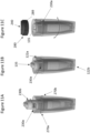
- Figure 12 shows an exploded perspective view of a cartridge assembly 320 according to an embodiment of the present disclosure.
- Figure 12 also shows a first portion 62 of an aerosol-generating device 40 and an adaptor member 380.
- the cartridge assembly 320 includes: a cartridge 330 and a housing 322 in the form of a mouthpiece. Unlike the cartridge assembly 120 of Figure 5 and cartridge assembly 220 of Figure 9 , the cartridge assembly 320 of the embodiment of Figure 12 does not include an insert member 170. Instead, the cartridge 330 is configured to be directly inserted into the housing 322.
- FIG 13 shows an exploded perspective view of the cartridge 330 of Figure 12 .
- the cartridge 330 of the embodiment comprises a heating assembly comprising a flat liquid permeable mesh heating element 128 held onto a heater cap 133.
- the heating assembly is arranged to fit within a device end of a main body 334 of the cartridge 330, and be in fluid communication with a storage container within the main body 334 of the cartridge, which holds liquid aerosol-forming substrate.
- the cartridge 330 also includes a mouth end portion 337.
- the mouth end portion may define at least part of the storage container.
- the mouth end portion may be substantially pointed.
- the mouth end portion 337 may be integrally formed with the main body 334, or may be a discrete element, which is connected to the main body 334.
- the cartridge 330 also includes a cartridge cap 335.
- the cap 335 comprises a base 335a which is configured to connect to the cartridge main body 334 by a snap fit engagement.
- the cap 335 also comprises a top 335b, which is configured to connect to, and at least partially cover, the base 335a.
- the base and top together define a cartridge air inlet 330a for air to flow into the cartridge and across the top of the heating element 128.
- the air can then continue to flow through a channel 330c, which passes along one side of the cartridge main body 334 and cartridge mouth end portion 337.
- a cartridge air outlet 330b At the end of the channel 330c. Air can therefore flow through the cartridge 330 from the air inlet 330a to the cartridge air outlet 330b, via the space above the heating element 128 and via the cartridge air channel 330c.
- the main body 334 of the cartridge 330 of the embodiment is not configured to move relative to the housing 322 once the cartridge 330 has been inserted into the housing 122. Instead, the main body 334 remains in a fixed position, both axially and radially. In this position, the cartridge air inlet 330a is axially and radially aligned with the housing air inlet 322a, and the cartridge air outlet 330b is axially and radially aligned with the housing air outlet 322b. Air can therefore flow between the cartridge air inlet 330a and the housing air inlet 322a. Air can also low between the cartridge air outlet 330b and the housing air outlet 322b.
- the cartridge cap 335a comprises a threaded member 335c disposed between the cartridge cap base 335a and cartridge cap top 335b.
- the threaded member 335c is configured to move between a first position, as shown in Figure 14A , and a second position, as shown in Figure 14B .
- the threaded member 335c When the threaded member 335c is in the first position, it provides a sealed enclosure about the heating element 128. Consequently, the threaded member 335c blocks air from flowing from the cartridge air inlet 330a to the heating element 128. It also blocks air from flowing from the cartridge air channel 330c to the heating element 128.
- Figure 14B shows the assembly when the threaded member 335c has been moved to the second position.
- the threaded member 335c In the second position, the threaded member 335c is spaced away from the heating element 128, such that a flow path exists between the threaded member 335c and the heating element 128. Air can therefore flow from the cartridge air inlet 330a, across the heating element 128 and on to the cartridge air channel 330c. Therefore, when the threaded member 335c is in the second position, an unrestricted airflow path exists from the housing air inlet 322a to the housing air outlet 322b, via the cartridge air inlet 330a, the fluid-permeable heating element 128, and the cartridge air outlet 330b.
- the adaptor member is attached to the device so that the adaptor member cannot rotate relative to the device.
- the adaptor member 380 is then inserted into the device end of the housing 322 to the position shown in Figure 14A .
- the adaptor member 380 can form a snap fit engagement with the housing 322 so that the adaptor member 380 and device 40 are axially fixed with respect to the housing 322, yet free to rotate relative to the housing 322.
- the adaptor member 380 can comprise a bayonet locking mechanism similar to that of the cartridge assembly 220 of Figure 9 , so that the adaptor member 380 can be held in an axially fixed position with respect to the housing 322, yet free to rotate relative to the housing 322, by at least some degrees.
- a protruding part 381 of the adaptor member 380 extends through an aperture 335d in the top 330b of the cartridge cap 335.
- the protruding part 381 engages with a surface of a recessed section of the threaded member 335c, in a similar manner to how a screwdriver tip engages with the head of a screw.
- the outer surface of the threaded member 335c has a first thread, which is engaged with a second thread on the inner surface of the cartridge cap base 335a.
- This arrangement means that as the device 40 and adaptor member 380 rotate relative to the cartridge body 334 and housing 322, the protruding part 381 of the adaptor member 380 engages with the inner surface of the threaded member 335c and causes the threaded member to move axially with respect to the rest of the cartridge 330.
- the threads of the threaded member 380 and cartridge cap base 335a are arranged such that clockwise rotation of the device 40 relative to the housing 322 causes the threaded member 335c to move towards the device 40, and away from the heating element 128.
- the threaded member 335c is spaced away from the heating element 128, such that a flow path exists between the threaded member 335c and the heating element 128, as shown in Figure 14B .
- air is free to flow from the cartridge air inlet 330a, across the heating element 128 and on to the cartridge air channel 330c.
- a user can then use the device 40 and cartridge assembly 320 to create an aerosol that they can inhale.
- the ability to move at least a part of the cartridge from a first position to a second position, such that air flow to the heating element 128 can be selectively blocked or opened means that leakage of liquid aerosol-forming substrate from the heating element to the exterior of the cartridge assembly, can be reduced.
- the consumer when the consumer is ready to use the aerosol-generating system, they can readily move part of the cartridge so that the heating element 128 is exposed to airflow, and consequently able to produce aerosol that can be released to the consumer.
Description
- The invention relates to aerosol-generating systems, such as handheld electrically operated aerosol-generating systems. In particular the invention relates to cartridges for aerosol-generating systems, containing a supply of aerosol-forming substrate and a heater assembly.
- Handheld electrically operated aerosol-generating systems that consist of a device portion comprising a battery and control electronics, and a cartridge portion comprising a supply of aerosol-forming substrate held in a storage portion and an electrically operated heater assembly acting as a vaporiser are known. A cartridge comprising both a supply of aerosol-forming substrate held in the storage portion and a vaporiser is sometimes referred to as a "cartomiser". The heater assembly may comprise a fluid-permeable heating element that is in contact with the aerosol-forming substrate held in the storage portion.
-
CN 2014 599 324 U Fig 2 ofCN 2014 599 324 U Fig 13 ofCN 2014 599 324 U Fig 14 ofCN 2014 599 324 U -
WO 2017/118347 A1 describes an opening and closing mechanism for a chamber of an electronic cigarette. The mechanism includes an inner ring and an outer ring. The inner ring is provided with a set of teeth arranged to cooperate with a gear. When the gear is driven it causes the inner ring to move relative to the outer ring, as shown inFigs 4 and5 ofWO 2017/118347 A1 . This can result in a closing of an airflow path in the electronic cigarette. -
WO 2017/129617 A1 describes a cartridge assembly for use in an aerosol-generating system, the cartridge assembly comprising a cartridge, a housing, a mouthpiece and at least one linkage. The cartridge comprises first and second compartments each having an air inlet and an air outlet. The housing encloses the cartridge, the housing comprising air inlets, air outlets and at least one guide slot. The mouthpiece comprises an air inlet in fluid communication with the housing air outlets. The at least one linkage extends through the at least one guide slot and is connected to the cartridge and the mouthpiece. The mouthpiece and the cartridge are rotatable with respect to the housing from a first position to a second position. When the cartridge is in the first position, the housing obstructs the air inlet and the air outlets of the first and second compartments. When the cartridge is in the second position, the air inlets and the air outlets of the first and second compartments are in fluid communication with the housing air inlets and the housing air outlets respectively. - A heater assembly with a fluid-permeable heating element can be fragile and may be easily damaged. Furthermore, when a liquid aerosol-forming substrate is used, small amounts of the liquid may leak through the fluid-permeable heating element when the cartridge is not in use, which can interfere with the electrical components of the system, or cause inconvenience for the consumer.
- It would be desirable to provide a cartridge assembly that is more robust and less likely to leak. It would also be desirable to provide a cartridge assembly having a reusable housing.
- According to the present invention, there is provided a cartridge for an aerosol-generating system, the cartridge comprising: a cartridge body comprising a cartridge main body and a cartridge cap configured to connect to the cartridge main body; and a fluid-permeable heating element disposed within the cartridge body, covered by the cartridge cap; wherein the cartridge body comprises at least one cartridge air inlet formed in the cartridge cap, and at least one cartridge air outlet; and a cartridge airflow path extending from the at least one cartridge air inlet to the at least one cartridge air outlet, via the fluid-permeable heating element; and wherein the cartridge cap comprises a threaded member disposed therein, the threaded member being configured to move within the cartridge body between: a first position, in which the threaded member blocks air from the cartridge air inlet from flowing to the cartridge air outlet, via the fluid-permeable heating element; and a second position, in which the threaded member is spaced away from the heating element to define an airflow path from the cartridge air inlet to the cartridge air outlet, via the fluid-permeable heating element; and wherein the threaded member is configured to move between the first and second positions by way of a threaded engagement between an outer threaded surface of the threaded member and a corresponding threaded inner surface on another part of the cartridge cap.
- Preferably, the cartridge further comprises a storage container within the cartridge body, said storage container containing a supply of liquid aerosol-forming substrate, and wherein the fluid-permeable heating element is positioned across an opening in the storage container. The storage container may be formed from one or more distinct pieces, which are disposed within the cartridge body. Alternatively, the storage container may be integrally formed within the cartridge body. In this case, inner surfaces of the cartridge body can define at least a portion of the boundary of the storage container. The cartridge body and the storage container may be formed form a mouldable plastics material, such as polypropylene (PP) or polyethylene terephthalate (PET).
- Preferably, the at least one cartridge air inlet is provided in the form of at least one opening in the main body of the cartridge. Preferably, the at least one cartridge air outlet is provided in the form of at least one opening in the main body of the cartridge. This may be advantageous when the housing includes an internal flow path extending within the housing to the housing air outlet. In particular, when the cartridge is in the first position, the at least one air outlet in the main body of the cartridge may be aligned with an upstream end of the internal flow path extending within the housing. This can allow air to flow unrestricted from the at least one air outlet in the main body of the cartridge to the housing air outlet, internal flow path extending within the housing.
- Preferably the cartridge cap is configured to connect to the cartridge main body to cover the fluid-permeable heating element. Preferably, the cartridge cap is provided with electrical connectors to form an electrical connection with the heating element. Preferably, the electrical connectors extend to an outer surface of the cartridge cap. Preferably, the electrical connectors are configured to form an electrical connection with a power supply in an aerosol-generating device, when the cartridge assembly is connected to the device. This may be achieved by arranging for the electrical connectors to connect to contact points in a first portion of the device. In another embodiment, this may be achieved by arranging for the electrical connectors of the cartridge cap to connect to an adaptor member, which is in turn, electrically connected to the contact points in the first portion of the aerosol-generating device.
- In some other embodiments, the cartridge cap comprises two or more components. For example, preferably the cartridge cap comprises a base configured to connect to the cartridge main body. The connection may be formed by a mechanical interlock structure. Preferably, the cartridge cap also comprises a top, which is configured to connect to, and at least partially cover, the cartridge cap base. The base and top may together define the cartridge air inlet for air to flow into the cartridge and across the top of the heating element. The air can then continue to flow along a cartridge air channel, which extends along one side of the cartridge. The cartridge air channel is preferably enclosed within the cartridge main body and, if present, the cartridge mouth end portion. The cartridge air channel may extend along one side of the storage container in the cartridge body. Preferably, the cartridge air outlet is disposed at the end of the cartridge air channel. Air can therefore flow through the cartridge from the cartridge air inlet to the cartridge air outlet, via the space above the heating element and via the cartridge air channel.
- The threaded member of the cartridge cap may be disposed between the cartridge cap base and cartridge cap top.
- The cartridge may be comprised in a cartridge assembly for an aerosol-generating system. The cartridge assembly may comprise: a housing having a mouth end and an opposed device end configured to connect to an aerosol-generating device, with at least one housing air outlet provided at the mouth end of the housing, and at least one housing air inlet provided upstream of the housing air outlet. The cartridge assembly also comprises a cartridge according to the present invention disposed within the housing. When the threaded member is in the first position, the threaded member blocks air from the housing air inlet from flowing to the housing air outlet, via the cartridge air inlet, the fluid-permeable heating element, and the cartridge air outlet; and when the threaded member is in the second position, in which the threaded member is spaced away from the heating element to define an airflow path from the housing air inlet to the housing air outlet, via the cartridge air inlet, the fluid-permeable heating element, and the cartridge air outlet.
- By arranging for the threaded member to be movable between the first and second positions, the airflow path across the fluid permeable heating element can be selectively opened and closed. A consumer can therefore select whether to have the airflow path open, for example when they wish to use the assembly in an aerosol-generating system; or whether to have the airflow path closed, for example when they do not wish to use the assembly in an aerosol-generating system. By arranging for the airflow path to be closed, when the assembly is not in use, the likelihood of accidental leakage of fluid from the assembly can be reduced.
- The cartridge may be removable from the housing. By arranging for the cartridge to be removable from the housing, it is possible to reuse the housing after disposing of the cartridge. In particular, when a supply of liquid aerosol-forming substrate has been fully consumed, the cartridge may be removed from the housing and discarded. The same housing may then be reused with a new cartridge.
- The cartridge assembly may be supplied in a pre-assembled configuration. In this configuration, the cartridge is already disposed within the housing. In this configuration, the cartridge may be temporarily affixed to the housing to prevent accidental removal of the cartridge from the housing.
- As an alternative to being supplied in a pre-assembled configuration, the cartridge assembly may be supplied in an unassembled configuration. In this case, the cartridge may be disposed outside of the housing but configured to be inserted into the housing, for example by a consumer. The cartridge may be configured to be inserted into the housing through an opening at the device end of the housing. Therefore, the cartridge may be comprised in a kit for an aerosol-generating system, and in particular, a kit for a cartridge assembly for an aerosol-generating system. The kit may comprise: a housing having a mouth end and an opposed device end configured to connect to an aerosol-generating device, wherein at least one housing air outlet is provided at the mouth end of the housing, and at least one housing air inlet is provided upstream of the housing air outlet; and a cartridge according to the present invention configured to be inserted into the housing. When the threaded member is in the first position, the threaded member blocks air from the housing air inlet from flowing to the housing air outlet, via the cartridge air inlet, the fluid-permeable heating element, and the cartridge air outlet; and when the threaded member is in the second position, the threaded member is spaced away from the heating element to define an airflow path from the housing air inlet to the housing air outlet, via the cartridge air inlet, the fluid-permeable heating element, and the cartridge air outlet.
- Preferably, a storage container is provided within the housing, said storage container containing a supply of liquid aerosol-forming substrate, and wherein when the cartridge is inserted into the housing, the fluid-permeable heating element is positioned across an opening in the storage container. The storage container and the housing may be fixed to each other by a mechanical fixing, or by welding or adhesive. Advantageously, the storage container and housing may be integrally formed. The housing and the storage container may be formed form a mouldable plastics material, such as polypropylene (PP) or polyethylene terephthalate (PET).
- The cartridge assembly may comprise an insert member. The insert member may be configured to be inserted into the housing. The insert member may be inserted through an opening at the device end of the housing. The insert member may be disposed between the cartridge and the housing, when the cartridge is in the housing. Preferably, the insert member is fixed to an inner surface of the housing.
- Preferably, the insert member has at least one insert member air inlet and at least one insert member air outlet. Preferably, the insert member air inlet is in the form of a first gap or hole in the insert member. Preferably, the insert member air outlet is in the form of a second gap or hole in the insert member.
- Preferably, the insert member is configured to connect to the housing and reside in a fixed position relative to the housing, when connected to the housing. Preferably, when the insert member is held in said fixed position, air is free to flow from the housing air inlet to the first gap in the insert member. Preferably, when the insert member is held in said fixed position, air is free to flow from the housing air outlet to the second gap in the insert member.
- The insert member may advantageously enable cartridges in accordance with the present invention to connect to a range of different housings, including prior art housings. That is, the insert member may function as an adaptor so that cartridges in accordance with the present invention can connect to a range of different housings, including prior art housings. The housing may comprise a mouth end portion. The mouth end portion may be configured to be inserted into a user's mouth. A user may suck on the mouth end portion to draw aerosol generated in the cartridge into the user's mouth. Alternatively, a separate mouthpiece portion may be provided, which can be attached to the housing. The housing air outlet is preferably provided in the mouth end portion of the housing.
- The housing may provide the external surface of the cartridge assembly, when the cartridge assembly has been assembled. The housing may therefore be referred to as external housing. The housing may be generally tubular. The housing may comprise a connecting portion at its device end. The connecting portion may comprise a mechanical interlock structure, such as a snap fitting or a screw fitting, configured to engage a corresponding interlock structure on an aerosol-generating device. The interlock structure may permit at least some rotation of the housing relative to the device, but prevent axial movement of the housing relative to the device.
- The cartridge body preferably comprises a main body configured to house the fluid-permeable heating element. Where the cartridge further comprises a storage container, preferably the storage container is within the cartridge main body. The cartridge main body may be substantially cylindrical.
- As will be described in more detail below, in some embodiments, the cartridge cap is a single piece which connects to the device end of the cartridge main body. The connection may be formed by a mechanical interlock structure, such as a snap fitting or a screw fitting, configured to engage a corresponding interlock structure on an aerosol-generating device.
- The threaded member is configured to move between a first position and a second position. When the threaded member is in the first position, it provides a sealed enclosure for the heating element. Consequently, when in the first position the threaded member can block air from flowing between the heating element and: the cartridge air inlet, the cartridge air outlet, or both. However, when the threaded member is in the second position, air can flow between the heating element and: the cartridge air inlet, the cartridge air outlet, or both.
- The threaded member can move between the first and second positions by way of a threaded engagement between an outer surface of the threaded member, and an inner surface of the cartridge cap base, cartridge cap top, or both. In particular, the outer surface of the threaded member may have a first thread, which is engaged with a second thread on the inner surface of the cartridge cap base, cartridge cap top, or both. Rotation of the threaded member relative to the rest of the cartridge can be initiated by rotation of an aerosol-generating device, which is connected to the cartridge assembly. In particular, the threaded member may have a receiving portion, such as a recessed portion, which is configured to receive a portion of the aerosol-generated device, or a portion of an adaptor member which is connectable to the aerosol generated device. The receiving portion of the threaded member can then engage with the device or adaptor member, such that rotation of the device or adaptor causes rotation of the threaded member relative to the rest of the cartridge. The cartridge cap top may comprise an opening for providing access to the receiving portion of the threaded member.
- The threaded member may be a substantially cylindrical plug. A recess may be provided in the upper surface of the substantially cylindrical plug to define the receiving portion. The recess may have any suitable screw drive shape, such as a slot, Phillips, Frearson, Robertson, hex, or the like.
- Although the cartridge cap base and cartridge cap top are described as two distinct components, it will be appreciated that they could be integrally formed as a single component with the threaded member disposed therein. Consequently, it will be appreciated that the cartridge air inlet may be formed in either a single or multicomponent cap, with the threaded member disposed therein. The cartridge cap could also be integrally formed with the cartridge main body.
- Accordingly, there is provided a cartridge assembly for an aerosol-generating system, the cartridge assembly comprising: a housing having a mouth end and an opposed device end configured to connect to an aerosol-generating device, wherein at least one housing air outlet is provided at the mouth end of the housing, and at least one housing air inlet is provided upstream of the housing air outlet; and
a cartridge disposed in the housing, wherein the cartridge comprises: a cartridge body comprising a cartridge main body and a cartridge cap configured to connect to the cartridge main body; a fluid-permeable heating element disposed within the cartridge body and covered by the cartridge cap; at least one cartridge air inlet formed in the cartridge cap; at least one cartridge air outlet; and a cartridge airflow path extending from the at least one cartridge air inlet to the at least one cartridge air outlet, via the fluid-permeable heating element; and wherein the cartridge cap comprises a threaded member disposed therein, the threaded member being configured to move between: a first position, in which the threaded member blocks air from the housing air inlet from flowing to the housing air outlet, via the cartridge air inlet, the fluid-permeable heating element, and the cartridge air outlet; and a second position, in which the threaded member is spaced away from the heating element to define an airflow path from the housing air inlet to the housing air outlet, via the cartridge air inlet, the fluid-permeable heating element, and the cartridge air outlet. - A kit for an aerosol-generating system, the kit comprising: a housing having a mouth end and an opposed device end configured to connect to an aerosol-generating device, wherein at least one housing air outlet is provided at the mouth end of the housing, and at least one housing air inlet is provided upstream of the housing air outlet; and a cartridge configured to be inserted into the housing, wherein the cartridge comprises: a cartridge body comprising a cartridge main body and a cartridge cap configured to connect to the cartridge main body, the cartridge cap comprising a threaded member disposed therein; a fluid-permeable heating element disposed within the cartridge body and covered by the cartridge cap; at least one cartridge air inlet formed in the cartridge cap; at least one cartridge air outlet; and a cartridge airflow path extending from the at least one cartridge air inlet to the at least one cartridge air outlet, via the fluid-permeable heating element; and wherein, when the cartridge is inserted into the housing, the threaded member is configured to be movable between: a first position, in which the threaded member blocks air from the housing air inlet from flowing to the housing air outlet, via the cartridge air inlet, the fluid-permeable heating element, and the cartridge air outlet; and a second position, in which the threaded member is spaced away from the heating element to define an airflow path from the housing air inlet to the housing air outlet, via the cartridge air inlet, the fluid-permeable heating element, and the cartridge air outlet.
- The cartridge body may comprise a mouth end portion. The mouth end portion may be attached to the mouth end of the cartridge main body. The mouth end portion may be configured to engage with the biasing member, if a biasing member is present. For example, the mouth end portion may be hollow and have an opening at its mouth end, configured to receive at least part of the biasing member, when the cartridge is inserted into the housing.
- The mouth end portion may provide a surface, which a device end of the biasing member can engage with when the cartridge is inserted into the housing. The mouth end portion may define at least part of the storage container. The mouth end portion may be substantially pointed. The mouth end portion may be integrally formed with the cartridge main body, or may be a discrete element, which is connected to the cartridge main body.
- The cartridge may comprise a locking system, such as a bayonet locking system, for temporarily affixing the cartridge to the housing. The locking system may restrict axial movement of the cartridge relative to the housing, but permit at least some radial movement of the cartridge relative to the housing. For example, when the cartridge is affixed to the housing by the locking system, the cartridge may be free to rotate by up to 90 degrees, relative to the housing. Such rotation occurs about the longitudinal axis of the housing.
- The locking system may comprise a guide track in the outer surface of the cartridge body, preferably in the outer surface of the mouth end portion of the cartridge body. A protrusion in the housing or insert member can be located in the guide track when the cartridge is first inserted into the housing. A first portion of the guide track defines an axially extending strip along which the protrusion can slide as the cartridge is pushed into the housing. Where the cartridge assembly includes a biasing member, it may be necessary to overcome the force of the biasing member in order to slide the protrusion all the way along the first portion of the guide track.
- Once the cartridge has been inserted sufficiently far into the housing, the protrusion reaches an end face of the first portion of the guide track. The end face may prevent further axial movement of the cartridge into the housing. At this point, a second portion of the guide track extends laterally around the cartridge, and therefore permits the cartridge to be rotated relative to the housing. When the protrusion is located in the second portion of the guide track, the cartridge is prevented from moving axially relative to the housing. This enables the cartridge to be temporarily fixed within the housing.
- The end of the second portion of the guide track may join with a third portion of the guide track. The third portion of the guide track may define a further an axially extending strip along which the protrusion can slide. The third portion of the guide track may have first and second end faces, which may restrict the extent of axial movement that the cartridge can have relative to the housing, when the protrusion of the housing is in the third portion of the guide track. The first end face of the third portion of the guide track may restrict the extent to which the cartridge can moving further into the housing. The second end face may stop the cartridge from being removed from the housing. The third portion of the guide track may be used to allow the cartridge to move between the first and second positions, relative to the housing.
- The cartridge assembly may further comprise an adaptor member configured to form a mechanical connection between an aerosol-generating device, and the cartridge, the housing or both the cartridge and the housing. The adaptor member may be configured to provide an electrical connection between the fluid-permeable heating element of the cartridge and a power supply of the aerosol-generating device. The adaptor member may comprise a locking system, such as a bayonet locking system, for affixing the housing to an aerosol generating device. The locking system may prevent axial movement of the housing relative to the device, but permit at least some radial movement of the housing relative to the device. For example, when the housing is affixed to the device by the locking system of the adaptor member, the housing may be free to rotate by up to 90 degrees, relative to the device. Such rotation occurs about the longitudinal axis of the housing.
- The locking system may comprise a guide track in the outer surface of the adaptor member. A protrusion in the housing or insert member can be located in the guide track when the cartridge assembly is first attached to the adaptor member. A first portion of the guide track defines an axially extending strip along which the protrusion can slide as the adaptor and housing are brought together. Once the adaptor and the housing have been brought together, the protrusion reaches an end face of the first portion of the guide track. The end face may prevent further axial movement of the housing towards the adaptor. At this point, a second portion of the guide track extends laterally around the adaptor member, and therefore permits the housing to be rotated relative to the adaptor member. When the protrusion is located in the second portion of the guide track, the housing is prevented from moving axially relative to the adaptor member. The adaptor member may have a first portion which is configured to mechanically engage with the cartridge, and cause the cartridge to rotate with the adaptor member and the device, relative to the housing. The second portion of the guide track may be used to allow the cartridge to move between the first and second positions, relative to the housing
- The fluid-permeable heating element may be part of a heater assembly in the cartridge. The heater assembly may comprise electrical contact pads connected to the fluid-permeable heating element.
- The heater assembly may comprise a heater cap, the heater cap comprising a hollow body with first and second heater cap openings, wherein the first heater cap opening is on an opposite end of the hollow body to the second heater cap opening. The fluid-permeable heating element may be substantially flat. The heating element may be mounted on the heater cap such that the heating element extends across the first heater cap opening. The heater cap may be coupled to an open end of the storage container so that the heating element extends across the open end of the storage container.
- As used herein, "electrically conductive" means formed from a material having a resistivity of 1x10⁻⁴ Ohm meter, or less. As used herein, "electrically insulating" means formed from a material having a resistivity of 1x10⁴ Ohm meter or more. As used herein, "fluid-permeable" in relation to a heater assembly means that the aerosol-forming substrate, in a gaseous phase and possibly in a liquid phase, can readily pass through the heating element of the heater assembly.
- The heater assembly may comprise a substantially flat heating element to allow for simple manufacture. Geometrically, the term "substantially flat" electrically conductive heating element is used to refer to an electrically conductive arrangement of filaments that is in the form of a substantially two dimensional topological manifold. Thus, the substantially flat electrically conductive heating element extends in two dimensions along a surface substantially more than in a third dimension. In particular, the dimensions of the substantially flat heating element in the two dimensions within the surface is at least five times larger than in the third dimension, normal to the surface. An example of a substantially flat heating element is a structure between two substantially imaginary parallel surfaces, wherein the distance between these two imaginary surfaces is substantially smaller than the extension within the surfaces. In some embodiments, the substantially flat heating element is planar. In other embodiments, the substantially flat heating element is curved along one or more dimensions, for example forming a dome shape or bridge shape.
- The term "filament" is used throughout the specification to refer to an electrical path arranged between two electrical contacts. A filament may arbitrarily branch off and diverge into several paths or filaments, respectively, or may converge from several electrical paths into one path. A filament may have a round, square, flat or any other form of cross-section. A filament may be arranged in a straight or curved manner.
- The heating element may be an array of filaments, for example arranged parallel to each other. Preferably, the filaments may form a mesh. The mesh may be woven or nonwoven. The mesh may be formed using different types of weave or lattice structures. Alternatively, the electrically conductive heating element consists of an array of filaments or a fabric of filaments. The mesh, array or fabric of electrically conductive filaments may also be characterized by its ability to retain liquid.
- In a preferred embodiment, a substantially flat heating element may be constructed from a wire that is formed into a wire mesh. Preferably, the mesh has a plain weave design. Preferably, the heating element is a wire grill made from a mesh strip.
- The electrically conductive filaments may define interstices between the filaments and the interstices may have a width of between 10 micrometres and 100 micrometres. Preferably, the filaments give rise to capillary action in the interstices, so that in use, liquid to be vaporized is drawn into the interstices, increasing the contact area between the heating element and the liquid aerosol-forming substrate.
- The electrically conductive filaments may form a mesh of size between 60 and 240 filaments per centimetre (+/- 10 percent). Preferably, the mesh density is between 100 and 140 filaments per centimetres (+/- 10 percent). More preferably, the mesh density is approximately 115 filaments per centimetre. The width of the interstices may be between 100 micrometres and 25 micrometres, preferably between 80 micrometres and 70 micrometres, more preferably approximately 74 micrometres. The percentage of open area of the mesh, which is the ratio of the area of the interstices to the total area of the mesh may be between 40 percent and 90 percent, preferably between 85 percent and 80 percent, more preferably approximately 82 percent.
- The electrically conductive filaments may have a diameter of between 8 micrometres and 100 micrometres, preferably between 10 micrometres and 50 micrometres, more preferably between 12 micrometres and 25 micrometres, and most preferably approximately 16 micrometres. The filaments may have a round cross section or may have a flattened cross-section.
- The area of the mesh, array or fabric of electrically conductive filaments may be small, for example less than or equal to 50 square millimetres, preferably less than or equal to 25 square millimetres, more preferably approximately 15 square millimetres. The size is chosen such to incorporate the heating element into a handheld system. Sizing of the mesh, array or fabric of electrically conductive filaments less or equal than 50 square millimetres reduces the amount of total power required to heat the mesh, array or fabric of electrically conductive filaments while still ensuring sufficient contact of the mesh, array or fabric of electrically conductive filaments to the liquid aerosol-forming substrate. The mesh, array or fabric of electrically conductive filaments may, for example, be rectangular and have a length between 2 millimetres to 10 millimetres and a width between 2 millimetres and 10 millimetres. Preferably, the mesh has dimensions of approximately 5 millimetres by 3 millimetres.
- The filaments of the heating element may be formed from any material with suitable electrical properties. Suitable materials include but are not limited to: semiconductors such as doped ceramics, electrically "conductive" ceramics (such as, for example, molybdenum disilicide), carbon, graphite, metals, metal alloys and composite materials made of a ceramic material and a metallic material. Such composite materials may comprise doped or undoped ceramics. Examples of suitable doped ceramics include doped silicon carbides. Examples of suitable metals include titanium, zirconium, tantalum and metals from the platinum group.
- Examples of suitable metal alloys include stainless steel, constantan, nickel-, cobalt-, chromium-, aluminum-, titanium-, zirconium-, hafnium-, niobium-, molybdenum-, tantalum-, tungsten-, tin-, gallium-, manganese- and iron-containing alloys, and super-alloys based on nickel, iron, cobalt, stainless steel, Timetal®, iron-aluminum based alloys and iron-manganese-aluminum based alloys. Timetal® is a registered trade mark of Titanium Metals Corporation. The filaments may be coated with one or more insulators. Preferred materials for the electrically conductive filaments are stainless steel and graphite, more preferably 300 series stainless steel like AISI 304, 316, 304L, 316L. Additionally, the electrically conductive heating element may comprise combinations of the above materials. A combination of materials may be used to improve the control of the resistance of the substantially flat heating element. For example, materials with a high intrinsic resistance may be combined with materials with a low intrinsic resistance. This may be advantageous if one of the materials is more beneficial from other perspectives, for example price, machinability or other physical and chemical parameters. Advantageously, a substantially flat filament arrangement with increased resistance reduces parasitic losses. Advantageously, high resistivity heaters allow more efficient use of battery energy.
- Preferably, the filaments are made of wire. More preferably, the wire is made of metal, most preferably made of stainless steel.
- The electrical resistance of the mesh, array or fabric of electrically conductive filaments of the heating element may be between 0.3 Ohms and 4 Ohms. Preferably, the electrical resistance is equal or greater than 0.5 Ohms. More preferably, the electrical resistance of the mesh, array or fabric of electrically conductive filaments is between 0.6 Ohms and 0.8 Ohms, and most preferably about 0.68 Ohms. The electrical resistance of the mesh, array or fabric of electrically conductive filaments is preferably at least an order of magnitude, and more preferably at least two orders of magnitude, greater than the electrical resistance of electrically conductive contact areas. This ensures that the heat generated by passing current through the heating element is localized to the mesh or array of electrically conductive filaments. It is advantageous to have a low overall resistance for the heating element if the system is powered by a battery. A low resistance, high current system allows for the delivery of high power to the heating element. This allows the heating element to heat the electrically conductive filaments to a desired temperature quickly.
- When the cartridge assembly comprises a storage container, the storage container may hold a liquid retention material for holding a liquid aerosol-forming substrate. The liquid retention material may be a foam, and sponge of collection of fibres. The liquid retention material may be formed from a polymer or co-polymer. In one embodiment, the liquid retention material is a spun polymer.
- Preferably, the storage container holds a capillary material for transporting liquid aerosol-forming substrate to the heating element. The capillary material may be provided in contact with the heating element. Preferably, the capillary material is arranged between the heating element and the retention material.
- The capillary material may be made of a material capable of guaranteeing that there is liquid aerosol-forming substrate in contact with at least a portion of the surface of the heating element. The capillary material may extend into interstices between the filaments. The heating element may draw liquid aerosol-forming substrate into the interstices by capillary action.
- A capillary material is a material that actively conveys liquid from one end of the material to another. The capillary material may have a fibrous or spongy structure. The capillary material preferably comprises a bundle of capillaries. For example, the capillary material may comprise a plurality of fibres or threads or other fine bore tubes. The fibres or threads may be generally aligned to convey liquid aerosol-forming substrate towards the heating element. Alternatively, the capillary material may comprise sponge-like or foam-like material. The structure of the capillary material forms a plurality of small bores or tubes, through which the liquid aerosol-forming substrate can be transported by capillary action. The capillary material may comprise any suitable material or combination of materials. Examples of suitable materials are a sponge or foam material, ceramic- or graphite-based materials in the form of fibres or sintered powders, foamed metal or plastics material, a fibrous material, for example made of spun or extruded fibres, such as cellulose acetate, polyester, or bonded polyolefin, polyethylene, terylene or polypropylene fibres, nylon fibres or ceramic. The capillary material may have any suitable capillarity and porosity so as to be used with different liquid physical properties. The liquid aerosol-forming substrate has physical properties, including but not limited to viscosity, surface tension, density, thermal conductivity, boiling point and vapour pressure, which allow the liquid aerosol-forming substrate to be transported through the capillary medium by capillary action.
- The aerosol-forming substrate is a substrate capable of releasing volatile compounds that can form an aerosol. The volatile compounds may be released by heating the aerosol-forming substrate.
- The aerosol-forming substrate may comprise plant-based material. The aerosol-forming substrate may comprise tobacco. The aerosol-forming substrate may comprise a tobacco-containing material containing volatile tobacco flavour compounds, which are released from the aerosol-forming substrate upon heating. The aerosol-forming substrate may alternatively comprise a non-tobacco-containing material. The aerosol-forming substrate may comprise homogenized plant-based material. The aerosol-forming substrate may comprise homogenized tobacco material. The aerosol-forming substrate may comprise at least one aerosol-former. The aerosol-forming substrate may comprise other additives and ingredients, such as flavourants.
- The heating element may have at least two electrically conductive contact pads. The electrically conductive contact pads may be positioned at an edge area of the heating element. Preferably, the at least two electrically conductive contact pads may be positioned on extremities of the heating element. An electrically conductive contact pad may be fixed directly to the electrically conductive filaments. An electrically conductive contact pad may comprise a tin patch. Alternatively, an electrically conductive contact pad may be integral with the electrically conductive filaments.
- The cartridge may be a disposable article to be replaced with a new cartridge once the liquid storage portion of the cartridge is empty or the amount of liquid in the cartridge is below a minimum volume threshold. When the cartridge comprises a storage container, preferably, the cartridge is pre-loaded with liquid aerosol-forming substrate.
- When the threaded member moves between the first and second positions of the invention, within the cartridge and relative to the housing, the rest of the cartridge may remain stationary relative to the housing.
- There is also provided an aerosol-generating system comprising a cartridge assembly in accordance with the above disclosure and an aerosol-generating device comprising a power supply and control electronics, wherein the cartridge assembly is configured to connect to the aerosol-generating device. When the cartridge assembly is connected to the aerosol-generating device, the fluid-permeable heater element may be electrically connected to the power supply.
- The aerosol-generating device may comprise a connecting portion for engagement with a corresponding connecting portion on the cartridge assembly.
- The aerosol-generating device may comprise at least one electrical contact element configured to provide an electrical connection to the heating element when the aerosol-generating device is connected to the cartridge assembly. The electrical contact element may be elongate. The electrical contact element may be spring-loaded. The electrical contact element may contact an electrical contact pad in the cartridge assembly.
- The power supply is advantageously a battery, such as a lithium ion battery. As an alternative, the power supply may be another form of charge storage device such as a capacitor. The power supply may require recharging. For example, the power supply may have sufficient capacity to allow for the continuous generation of aerosol for a period of around six minutes or for a period that is a multiple of six minutes. In another example, the power supply may have sufficient capacity to allow for a predetermined number of puffs or discrete activations of the heater assembly.
- The control electronics may comprise a microcontroller. The microcontroller is preferably a programmable microcontroller. The electric circuitry may comprise further electronic components. The electric circuitry may be configured to regulate a supply of power to the heater assembly. Power may be supplied to the heater assembly continuously following activation of the system or may be supplied intermittently, such as on a puff-by-puff basis. The power may be supplied to the heater assembly in the form of pulses of electrical current.
- Preferably, the aerosol-generating system is a handheld system. Preferably, the aerosol-generating system is portable. The aerosol-generating system may have a size comparable to a conventional cigar or cigarette. The aerosol-generating device system may have a total length between approximately 30 millimetres and approximately 150 millimetres. The aerosol-generating device system may have an external diameter between approximately 5 millimetres and approximately 30 millimetres.
- An embodiment of the invention will now be described, by way of example only, with reference to the accompanying drawings, in which:
-
Figure 1 shows a perspective view of an aerosol-generating system having a prior art cartridge assembly and an aerosol-generating device; -
Figure 2 shows an exploded perspective view of the cartridge assembly ofFigure 1 ; -
Figure 2 shows a perspective view of the device ofFigure 1 ; -
Figure 4 shows a sectional view of the cartridge assembly ofFigure 1 ; -
Figure 5 shows an exploded perspective view of a cartridge assembly not according to the present invention, and a first portion of an aerosol-generating device; -
Figure 6 shows an exploded perspective view of the cartridge ofFigure 5 ; -
Figure 7A shows a sectional view of the cartridge assembly ofFigure 5 , in a first configuration; -
Figure 7B shows a sectional view of the cartridge assembly ofFigure 5 , in a second configuration; -
Figure 8 shows an enlarged view of a portion of the cartridge assembly ofFigure 5 ; -
Figure 9 shows an exploded perspective view of a cartridge assembly not according to the present invention and a first portion of an aerosol-generating device and an adaptor member; -
Figure 10 shows an exploded perspective view of the cartridge ofFigure 9 ; -
Figure 11A shows a sectional view of the cartridge assembly ofFigure 9 , in an initial configuration; -
Figure 11B shows a sectional view of the cartridge assembly ofFigure 9 , in a first configuration; -
Figure 11C shows a sectional view of the cartridge assembly ofFigure 9 , in a second configuration; -
Figure 12 shows an exploded perspective view of a cartridge assembly according to an embodiment of the present disclosure, together with a first portion of an aerosol-generating device and an adaptor member; -
Figure 13 shows an exploded perspective view of the cartridge ofFigure 12 ; -
Figure 14A shows a sectional view of the cartridge assembly ofFigure 12 , in a first configuration; and -
Figure 14B shows a sectional view of the cartridge assembly ofFigure 12 , in a second configuration. -
Figure 1 is a perspective view of an aerosol-generatingsystem 10 comprising a priorart cartridge assembly 20, and an aerosol-generatingdevice 40 that are coupled together. -
Figure 2 is an exploded view of the priorart cartridge assembly 20 shown inFigure 1 . Thecartridge assembly 20 comprises ahousing 22, which forms a mouthpiece for the system. Within the housing there is astorage container 24 holding liquid aerosol-forming substrate 26. Thestorage container 24 is open at the device end. A heater assembly comprising a flat liquid permeablemesh heating element 28 held onto aheater cap 33, is arranged to cover the open device end of thestorage container 24. Aliquid retention 32 material is positioned within the cap. Acapillary material 31 is positioned between the heater assembly and theretention material 32. A protective cover orcap 30 is fitted to the housing to retain the heater assembly in a fixed position relative to thestorage container 24. The protective cover also covers theheating element 28 and protects it from damage. -
Figure 3 is a perspective view of an aerosol-generatingdevice 40. Thedevice 40 comprises ahousing 46, holding a power supply, in the form of a lithium ion battery 42 and control circuitry 44. The device also comprises spring loadedelectrical contact elements 45, configured to contact electrical contact pads on the heater assembly in the cartridge. Thecontact elements 45 are electrically coupled to the power supply, so that when thecartridge assembly 20 is connected to thedevice 40, electrical power can be supplied to themesh heating element 28 in thecartridge assembly 20. - A
button 41 is provided, that actuates a switch in the control circuitry to activate the device. When the device is activated, the control circuitry supplies power from the battery to the heater in the cartridge. The control circuitry may be configured to control the supply of power to the heater after activation in many different ways, as is known in the art. For example, the control circuitry may be configured to control the power supplied to the heater based on one or more of: a temperature of the heater, a detected airflow through the system, a time following activation, a determined or estimated liquid amount in the cartridge, an identity of the cartridge and ambient conditions. - The
cartridge 20 anddevice 40 are arranged to couple to one another by a push fitting. Thecartridge housing 22 is shaped to allow it to couple to thedevice 40 in only two orientations, ensuring that spring loadedelectrical contact elements 45 can contact the contact pads of the heater assembly via openings in theprotective cover 30. A connectingrib 48 of the device portion engages a recess 25 on thehousing 22 to retain the cartridge and device portion together. - As best seen from
Figure 4 , the priorart cartridge assembly 20 comprises a supply of liquid aerosol-formingsubstrate 24 and heater assembly. The device functions to supply electrical power to the heater assembly in the priorart cartridge assembly 20 in order to vaporise the liquid aerosol-forming substrate. The vaporised aerosol-forming substrate is entrained in an airflow through the system, the airflow resulting from a user puffing on amouthpiece 23 of the priorart cartridge assembly 20. The vaporised aerosol-forming substrate cools in the airflow to form an aerosol before being drawn into a user's mouth. - The airflow path in
Figure 4 is illustrated by arrows. In particular, when a user draws on the mouth end 23 of thehousing 22, air is drawn into the cartridge assembly at an upstreamhousing air inlet 22a. The air then passes through anair inlet 30a in theprotective cap 30, and past the liquidpermeable heating element 28. The vaporised aerosol-forming substrate is then drawn by the air along the flow path and through anair outlet 30b in theprotective cap 30, before finally exiting theassembly 20 at ahousing air outlet 22b at the mouth end 23 of thehousing 22. In this prior art arrangement there is a possibility of liquid leaking out of thecartridge assembly 20 through one or both ofhousing air inlet 22a andhousing air outlet 22b. -
Figure 5 shows an exploded perspective view of acartridge assembly 120 and afirst portion 62 of an aerosol-generating device. Thecartridge assembly 120 ofFigure 5 is not according to the present invention because it does not comprise a threaded member disposed therein as required in appended claim 1. Namely, the cartridge assembly ofFigure 5 does not comprise a threaded member, wherein the threaded member is configured to move between: a first position, in which the threaded member blocks air from a housing air inlet from flowing to a housing air outlet, via a cartridge air inlet, a fluid-permeable heating element, and a cartridge air outlet; and a second position, in which the threaded member is spaced away from the heating element to define an airflow path from the housing air inlet to the housing air outlet, via the cartridge air inlet, the fluid-permeable heating element, and the cartridge air outlet. - The
cartridge assembly 120 ofFigure 5 includes: acartridge 130, ahelical spring 150, aninsert member 170, and ahousing 122 in the form of a mouthpiece. It will be appreciated that a single housing item could be provided instead of both theinsert member 170, and thehousing 122. The housing includes ahousing air inlet 122a and ahousing air outlet 122b. -
Figure 5 depicts an exploded view of components of thecartridge assembly 120. Thecartridge assembly 120 may be supplied in an assembled configuration, in which case theinsert member 170 and thespring 150 are pre-fixed to the inside of thehousing 122. Thecartridge 130 can be removable from thehousing 122. When thecartridge 120 is disposed within thehousing 122, thecartridge 120 is positioned within theinsert member 170. -
Figure 6 shows an exploded perspective view of thecartridge 130 ofFigure 5 . The cartridge comprises a heating assembly comprising a flat liquid permeablemesh heating element 128 held onto aheater cap 133. The heating assembly is arranged to fit within a device end of amain body 134 of thecartridge 130, and be in fluid communication with a storage container within themain body 134 of the cartridge, which holds liquid aerosol-forming substrate. The main body of thecartridge 130 includes an aperture which forms acartridge air inlet 130a and an aperture which forms acartridge air outlet 130b. The apertures are positioned above the heater assembly when the heater assembly is placed within the cartridge main body. This enables air to flow from theinlet 130a to theoutlet 130b across the top of theheating element 128. This enables vaporised aerosol-forming substrate to be entrained in the airflow as it passes through thecartridge 130. - The
cartridge 130 also includes acartridge cap 133, which is configured to connect to the cartridgemain body 134, and cover the fluid-permeable heating element 128. The cartridge cap is provided withelectrical connectors 136 to form an electrical connection with theheating element 128. Theelectrical connectors 136 extend to an outer surface of thecartridge cap 135. This allows the electrical connectors to form an electrical connection with a power supply in an aerosol-generatingdevice 40, when thecartridge assembly 120 is connected to thedevice 40. - The
cartridge 130 also includes amouth end portion 137, which is formed as a hollow tip. The end of thehollow tip 137 is open and configured to receive at least part of thehelical spring 150, when the cartridge is inserted into thehousing 122. Thehollow tip 137 provides a surface, which a device end of thespring 150 can engage with when the cartridge is inserted into thehousing 122. This can be best seen fromFigures 7A and 7B . - In particular, as shown in
Figure 7A , when thecartridge 130 is inserted into thehousing 122 through its device end, thecartridge 130 resides at a first position within thehousing 122. In this position the surface within thehollow tip 137 of thecartridge 130 has engaged with the device end of thespring 150. The biasing action of thespring 150 restricts thecartridge 130 from moving further into thehousing 122. - In the position shown in
Figure 7A , air from thehousing air inlet 122a can pass into the housing and through afirst gap 170a in theinsert member 170. However, the air is then blocked from flowing into thecartridge 130 because thecartridge air inlet 130a is not aligned with thefirst gap 170a in theinsert member 170. In this arrangement, this is because thecartridge air inlet 130a is located at a different axial position within thehousing 122, when compared to the axial position of thefirst gap 170a of theinsert member 170. The same is true for thecartridge air outlet 130b and thesecond gap 170b of theinsert member 170. - The rubber O-
rings 138 on the outer surface of the cartridge body also engage with the inner surface of theinsert member 170 to provide a seal around thecartridge air inlet 130a andcartridge air outlet 130b. - Therefore, in the configuration of
Figure 7A , air is blocked from flowing from thehousing air inlet 122a to thehousing air outlet 122b, via thecartridge air inlet 130a, the fluid-permeable heating element 128, and thecartridge air outlet 130b. - However, when the
cartridge assembly 120 is connected to anaerosol generating device 40, afirst portion 62 of thedevice 40 engages with thecartridge cap 135, and overcomes the biasing force of thehelical spring 150 to push thecartridge 130 further into thehousing 122. When thedevice 40 is fully connected to thecartridge assembly 120, thecartridge 130 resides within thehousing 122 at the position shown inFigure 7B . - In this position, the
cartridge air inlet 130a is axially aligned with thefirst gap 170a in theinsert member 170, and thecartridge air outlet 130b is axially aligned with thesecond gap 170b in theinsert member 170. Consequently, air is free to flow from thehousing air inlet 122a to thehousing air outlet 122b, via thecartridge air inlet 130a, the fluid-permeable heating element 128, and thecartridge air outlet 130b. - As can be best seen from
Figures 5 and8 , the cartridge body further comprises a guide mechanism 139 which is configured to temporarily retain the cartridge within thehousing 122, and further configured to restrict the extent of axial movement that thecartridge 130 can have within thehousing 122. - In particular, the outer surface of the cartridge body comprises a guide track 139, in which a protrusion in the
housing 122 or insertmember 170 can be located when the cartridge is first inserted into thehousing 122. In particular, the guide track 139 defines a bayonet locking mechanism to ensure that thecartridge 130 can be retained in thehousing 122 after insertion. The locking mechanism includes afirst portion 139a of the guide track, which the protrusion can be located in, when the cartridge is first placed into thehousing 122. - Once located in this
first portion 139a of the guide track, the protrusion can slide axially along saidfirst portion 139a, as thecartridge 130 moves into thehousing 122. The protrusion then reaches an end face of thefirst portion 139a of the guide track, which prevents further axial movement of thecartridge 130 into thehousing 122. - However, at this point, a second portion of the guide track 139 extends laterally around the
cartridge 130, and therefore permits thecartridge 130 to be rotated relative to thehousing 122. As thecartridge 130 is rotated relative to thehousing 122, the protrusion moves laterally along thesecond portion 139b of the guide track until it reaches a third portion 139c of the guide track. - The third portion 139c of the guide track is an axially extending strip having first and second end faces 139d, 139e, which restrict the extent of axial movement that the
cartridge 130 can have within thehousing 122. Thefirst end face 139d of the third portion 139c of the track 139 restricts the extent to which thecartridge 130 can moving further into thehousing 122, by engaging with the protrusion of the housing or insert member. Thesecond end face 139e stops thecartridge 130 from being removed from thehousing 122, by engaging with the protrusion of the housing or insert member. - In order to remove the
cartridge 130 from thehousing 122, the housing must be moved relative to the cartridge, such that the protrusion retraces its path along the second portion of the track, and then along the first portion of the track 139. The arrows inFigure 8 indicate the path that the protrusion can follow when moving in the guide track 139. -
Figure 9 shows an exploded perspective view of acartridge assembly 220 together with a first portion of an aerosol-generatingdevice 62 and anadaptor member 280. Thecartridge assembly 220 ofFigure 9 is not according to the present invention because it does not comprise a threaded member disposed therein as required in appended claim 1. Namely, thecartridge assembly 220 ofFigure 9 does not comprise a threaded member, wherein the threaded member is configured to move between: a first position, in which the threaded member blocks air from a housing air inlet from flowing to a housing air outlet, via a cartridge air inlet, a fluid-permeable heating element, and a cartridge air outlet; and a second position, in which the threaded member is spaced away from the heating element to define an airflow path from the housing air inlet to the housing air outlet, via the cartridge air inlet, the fluid-permeable heating element, and the cartridge air outlet. - The
cartridge assembly 220 includes: acartridge 230, ahelical spring 150, aninsert member 170, and ahousing 122 in the form of a mouthpiece. It will be appreciated that a single housing item could be provided instead of both theinsert member 170, and thehousing 122. The housing includes ahousing air inlet 122a and ahousing air outlet 122b. Thehelical spring 150,insert member 170, andhousing 122 can be the same as those described above in respect of thecartridge assembly 120 ofFigure 5 . -
Figure 10 shows an exploded perspective view of thecartridge 230 ofFigure 9 . As with thecartridge 130 ofFigure 6 , thecartridge 230 ofFigure 10 comprises a heating assembly comprising a flat liquid permeablemesh heating element 128 held onto aheater cap 133. The heating assembly is arranged to fit within a device end of amain body 234 of thecartridge 230, and be in fluid communication with a storage container within themain body 234 of the cartridge, which holds liquid aerosol-forming substrate. The main body of thecartridge 230 includes an aperture which forms acartridge air inlet 230a and an aperture which forms acartridge air outlet 230b. The apertures are positioned above the heater assembly when the heater assembly is placed within the cartridge main body. This enables air to flow from theinlet 230a to theoutlet 230b across the top of theheating element 128. This enables vaporised aerosol-forming substrate to be entrained in the airflow as it passes through thecartridge 230. - The
cartridge 230 also includes acartridge cap 135, which is configured to connect to the cartridgemain body 234, and cover the fluid-permeable heating element 128. The cartridge cap is provided withelectrical connectors 136 to form an electrical connection with theheating element 128. Theelectrical connectors 136 extend to an outer surface of thecartridge cap 135. This allows the electrical connectors to form an electrical connection with a power supply in an aerosol-generatingdevice 40, when thecartridge assembly 120 is connected to thedevice 40. - The
cartridge 130 also includes amouth end portion 237, which is formed as a hollow tip. The end of thehollow tip 237 is open and configured to receive at least part of thehelical spring 150, when the cartridge is inserted into thehousing 122. Thehollow tip 237 provides a surface, which a device end of thespring 150 can engage with when the cartridge is inserted into thehousing 122. This can be best seen fromFigures 11A and 11B . - Unlike the cartridge of
Figure 5 , the cartridge ofFigure 9 does not include a guide track 139, which defines a bayonet locking mechanism. Instead, the outer surface of theadaptor member 280 is provided with a bayonet locking mechanism, in the form of a guide track in its outer surface. Theadaptor member 280 is connected to thefirst portion 62 of the device, and held in a rotationally fixed position relative to thedevice 40. - Before the
device 40 andadaptor member 280 are first attached to thecartridge assembly 230, the cartridge assembly has an initial configuration, as shown inFigure 11A . In this configuration, thecartridge 230 rests onspring 150, and part of thecartridge 230 is disposed within thehousing 122. Thecartridge cap 135,air inlet 230a, andair outlet 230b are positioned outside of thehousing 122. Due to the presence of aguide protrusion 239 on the outer surface of the cartridgemain body 234, the initial orientation of thecartridge 230 is such that the airflow passage between thecartridge air inlet 230a andcartridge air outlet 230b is radially misaligned from thefirst gap 170a andsecond gap 170b. - When the
device 40 andadaptor member 280 are first attached to thecartridge assembly 230, a protrusion in thehousing 122 is configured to slide into a first portion of theguide track 289 in theadaptor member 280. - The first portion of the
guide track 289 is an axially extending strip, and therefore as the device and cartridge assembly are brought together, the protrusion slides along the first portion of theguide track 289 until it reaches a first end face of thetrack 289. At this point, thecartridge 230 andhousing 122 have the configuration shown inFigure 11B . In this configuration, the cartridge is positioned relative to the housing such that air from thehousing air inlet 122a can pass into thehousing 122 and through afirst gap 170a in theinsert member 170. However, the air is then blocked from flowing into thecartridge 230 because thecartridge air inlet 230a is not radially aligned with thefirst gap 170a in theinsert member 170. This is because thecartridge air inlet 230a is located at a different radial position within thehousing 122, when compared to the radial position of thefirst gap 170a of theinsert member 170. The same is true for thecartridge air outlet 230b and thesecond gap 170b of theinsert member 170. - The rubber seals 238 which surround the apertures for the
cartridge air inlet 230a andcartridge air outlet 230a also engage with the inner surface of theinsert member 170 to provide a seal around thecartridge air inlet 130a andcartridge air outlet 130b. - Therefore, in the configuration of
Figure 11B , air is blocked from flowing from thehousing air inlet 122a to thehousing air outlet 122b, via thecartridge air inlet 130a, the fluid-permeable heating element 128, and thecartridge air outlet 130b. - However, when the
aerosol generating device 40 andadaptor member 280 are rotated relative to thehousing 122, theadaptor member 280 mechanically engages with thecartridge cap 135 and causes thecartridge 230 to also rotate relative to thehousing 122. During this rotation, the protrusion in thehousing 122 is able to slide along a second portion of theguide track 289 in theadaptor member 280. - After an approximate 90 degree rotation, the
cartridge 230 andhousing 122 have the configuration shown inFigure 11C . In this position, thecartridge air inlet 230a is now radially aligned with thefirst gap 170a in theinsert member 170, and thecartridge air outlet 230b is now radially aligned with thesecond gap 170b in theinsert member 170. Consequently, air is free to flow from thehousing air inlet 122a to thehousing air outlet 122b, via thecartridge air inlet 230a, the fluid-permeable heating element 128, and thecartridge air outlet 230b. - In order to remove the
cartridge 230 from thehousing 122, the housing must be first rotated relative to thedevice 40 andcartridge 230, such that the protrusion in thehousing 122 retraces its path along the second portion of the track in theadaptor member 280. After this, thehousing 122 and thedevice 40 are moved axially away from one another, such that the protrusion in thehousing 122 retraces its path along the first portion of the track in theadaptor member 280. When thedevice 40 has been disconnected from thecartridge assembly 220, thespring 150 is able to push thecartridge 230 away from thehousing 122 to the raised position shown inFigure 11A . -
Figure 12 shows an exploded perspective view of acartridge assembly 320 according to an embodiment of the present disclosure.Figure 12 also shows afirst portion 62 of an aerosol-generatingdevice 40 and anadaptor member 380. - The
cartridge assembly 320 includes: acartridge 330 and ahousing 322 in the form of a mouthpiece. Unlike thecartridge assembly 120 ofFigure 5 andcartridge assembly 220 ofFigure 9 , thecartridge assembly 320 of the embodiment ofFigure 12 does not include aninsert member 170. Instead, thecartridge 330 is configured to be directly inserted into thehousing 322. -
Figure 13 shows an exploded perspective view of thecartridge 330 ofFigure 12 . As with thecartridge 130 ofFigure 5 andcartridge 230 ofFigure 9 , thecartridge 330 of the embodiment comprises a heating assembly comprising a flat liquid permeablemesh heating element 128 held onto aheater cap 133. The heating assembly is arranged to fit within a device end of amain body 334 of thecartridge 330, and be in fluid communication with a storage container within themain body 334 of the cartridge, which holds liquid aerosol-forming substrate. Thecartridge 330 also includes amouth end portion 337. The mouth end portion may define at least part of the storage container. The mouth end portion may be substantially pointed. Themouth end portion 337 may be integrally formed with themain body 334, or may be a discrete element, which is connected to themain body 334. - The
cartridge 330 also includes acartridge cap 335. Thecap 335 comprises abase 335a which is configured to connect to the cartridgemain body 334 by a snap fit engagement. Thecap 335 also comprises a top 335b, which is configured to connect to, and at least partially cover, thebase 335a. The base and top together define acartridge air inlet 330a for air to flow into the cartridge and across the top of theheating element 128. The air can then continue to flow through achannel 330c, which passes along one side of the cartridgemain body 334 and cartridgemouth end portion 337. At the end of thechannel 330c is acartridge air outlet 330b. Air can therefore flow through thecartridge 330 from theair inlet 330a to thecartridge air outlet 330b, via the space above theheating element 128 and via thecartridge air channel 330c. - Unlike the
cartridge 130 ofFigure 5 and thecartridge 230 ofFigure 9 , themain body 334 of thecartridge 330 of the embodiment is not configured to move relative to thehousing 322 once thecartridge 330 has been inserted into thehousing 122. Instead, themain body 334 remains in a fixed position, both axially and radially. In this position, thecartridge air inlet 330a is axially and radially aligned with thehousing air inlet 322a, and thecartridge air outlet 330b is axially and radially aligned with thehousing air outlet 322b. Air can therefore flow between thecartridge air inlet 330a and thehousing air inlet 322a. Air can also low between thecartridge air outlet 330b and thehousing air outlet 322b. - In order to provide a blocking mechanism for air flow in the embodiment of
Figure 12 , thecartridge cap 335a comprises a threadedmember 335c disposed between thecartridge cap base 335a andcartridge cap top 335b. The threadedmember 335c is configured to move between a first position, as shown inFigure 14A , and a second position, as shown inFigure 14B . When the threadedmember 335c is in the first position, it provides a sealed enclosure about theheating element 128. Consequently, the threadedmember 335c blocks air from flowing from thecartridge air inlet 330a to theheating element 128. It also blocks air from flowing from thecartridge air channel 330c to theheating element 128. Therefore, when the threadedmember 335c is in the first position, air is blocked from flowing from thehousing air inlet 322a to thehousing air outlet 322b, via thecartridge air inlet 330a, the fluid-permeable heating element 128, and thecartridge air outlet 330b. -
Figure 14B shows the assembly when the threadedmember 335c has been moved to the second position. In the second position, the threadedmember 335c is spaced away from theheating element 128, such that a flow path exists between the threadedmember 335c and theheating element 128. Air can therefore flow from thecartridge air inlet 330a, across theheating element 128 and on to thecartridge air channel 330c. Therefore, when the threadedmember 335c is in the second position, an unrestricted airflow path exists from thehousing air inlet 322a to thehousing air outlet 322b, via thecartridge air inlet 330a, the fluid-permeable heating element 128, and thecartridge air outlet 330b. - With references to
Figures 14A and 14B , the following describes how the threadedmember 335c can be moved between its first and second positions. - As shown in
Figure 14A , when thedevice 40 is first connected to thecartridge assembly 320, the threadedmember 335c is in the first position. Thecartridge 330 is held within the housing in a fixed position relative to thehousing 322. That is, the cartridge main body 324 cannot rotate relative to thehousing 322. - The adaptor member is attached to the device so that the adaptor member cannot rotate relative to the device.
- The
adaptor member 380 is then inserted into the device end of thehousing 322 to the position shown inFigure 14A . Theadaptor member 380 can form a snap fit engagement with thehousing 322 so that theadaptor member 380 anddevice 40 are axially fixed with respect to thehousing 322, yet free to rotate relative to thehousing 322. Alternatively, theadaptor member 380 can comprise a bayonet locking mechanism similar to that of thecartridge assembly 220 ofFigure 9 , so that theadaptor member 380 can be held in an axially fixed position with respect to thehousing 322, yet free to rotate relative to thehousing 322, by at least some degrees. - A
protruding part 381 of theadaptor member 380 extends through anaperture 335d in the top 330b of thecartridge cap 335. The protrudingpart 381 engages with a surface of a recessed section of the threadedmember 335c, in a similar manner to how a screwdriver tip engages with the head of a screw. The outer surface of the threadedmember 335c has a first thread, which is engaged with a second thread on the inner surface of thecartridge cap base 335a. This arrangement means that as thedevice 40 andadaptor member 380 rotate relative to thecartridge body 334 andhousing 322, the protrudingpart 381 of theadaptor member 380 engages with the inner surface of the threadedmember 335c and causes the threaded member to move axially with respect to the rest of thecartridge 330. In particular, the threads of the threadedmember 380 andcartridge cap base 335a, are arranged such that clockwise rotation of thedevice 40 relative to thehousing 322 causes the threadedmember 335c to move towards thedevice 40, and away from theheating element 128. After approximately 90 degrees of clockwise rotation, the threadedmember 335c is spaced away from theheating element 128, such that a flow path exists between the threadedmember 335c and theheating element 128, as shown inFigure 14B . At this point, air is free to flow from thecartridge air inlet 330a, across theheating element 128 and on to thecartridge air channel 330c. A user can then use thedevice 40 andcartridge assembly 320 to create an aerosol that they can inhale. - When a user has finished using the
device 40 andcartridge assembly 320 for inhaling an aerosol, they can rotate thedevice 40 anti-clockwise with respect to thehousing 322, by around 90 degrees. This causes the threadedmember 335c to be rotated anti-clockwise relative to the rest of thecartridge 330, and therefore moved towards theheating element 128. The threaded member can therefore revert to the position shown inFigure 14A and thus blocks air from flowing toheating element 128. - In each of the cartridge assemblies of
Figures 5 ,9 and12 described above with respect to the drawings, the ability to move at least a part of the cartridge from a first position to a second position, such that air flow to theheating element 128 can be selectively blocked or opened, means that leakage of liquid aerosol-forming substrate from the heating element to the exterior of the cartridge assembly, can be reduced. This means that when the cartridge assembly is not being used to produce an aerosol, a consumer can be more confident that there will not be any leakage of any liquid aerosol-forming substrate. However, when the consumer is ready to use the aerosol-generating system, they can readily move part of the cartridge so that theheating element 128 is exposed to airflow, and consequently able to produce aerosol that can be released to the consumer.
Claims (11)
- A cartridge (330) for an aerosol-generating system, the cartridge (330) comprising:a cartridge body comprising a cartridge main body (334) and a cartridge cap (335) configured to connect to the cartridge main body (334);
anda fluid-permeable heating element (128) disposed within the cartridge body, covered by the cartridge cap (335);wherein the cartridge body comprises at least one cartridge air inlet (330a) formed in the cartridge cap (335), and at least one cartridge air outlet (330b); and a cartridge airflow path extending from the at least one cartridge air inlet (330a) to the at least one cartridge air outlet (330b), via the fluid-permeable heating element (128);wherein the cartridge cap (335) comprises Z r a threaded member disposed therein, the threaded member being configured to move within the cartridge body between:a first position, in which the threaded member blocks air from the cartridge air inlet (330a) from flowing to the cartridge air outlet (330b), via the fluid-permeable heating element (128); anda second position, in which the threaded member is spaced away from the heating element (128) to define an airflow path from the cartridge air inlet (330a) to the cartridge air outlet (330b), via the fluid-permeable heating element (128); andwherein the threaded member is configured to move between the first and second positions by way of a threaded engagement between an outer threaded surface of the threaded member and a corresponding threaded inner surface on another part of the cartridge cap (335). - A cartridge (330) according to claim 1, further comprising a storage container within the cartridge body, said storage container containing a supply of liquid aerosol-forming substrate, and wherein the fluid-permeable heating element (128) is positioned across an opening in the storage container.
- A cartridge (330) according to claim 1 or claim 2, wherein
the at least one cartridge air outlet (130b) comprises at least one opening in the main body of the cartridge. - A cartridge (330) according to any one of the preceding claims, wherein the cartridge cap (335) is provided with electrical connectors (136) to form an electrical connection with the heating element (128).
- A cartridge (330) according to any one of the preceding claims, wherein the cartridge cap (335) comprises a base (335a) configured to connect to the cartridge main body (334), and a top (335b), which is configured to connect to, and at least partially cover, the cartridge cap base (335a), and wherein the cartridge cap base (335a) and cartridge cap top (335b) together define the at least one cartridge air inlet (330a) for air to flow into the cartridge and across the top of the heating element (128).
- A cartridge (330) according to claim 5, wherein the threaded member (335c) is disposed between the cartridge cap base (335a) and cartridge cap top (335b).
- A cartridge assembly (320) for an aerosol-generating system (10), the cartridge assembly (320) comprising:a housing (322) having a mouth end and an opposed device end configured to connect to an aerosol-generating device, wherein at least one housing air outlet (322b) is provided at the mouth end of the housing (322), and at least one housing air inlet (322a) is provided upstream of the housing air outlet (322b); anda cartridge (330) according to claim 1 disposed in the housing (322); andwherein when the threaded member is in the first position, the threaded member (335c) blocks air from the housing air inlet (322a) from flowing to the housing air outlet (322b), via the cartridge air inlet (330a), the fluid-permeable heating element (128), and the cartridge air outlet (330b); andwherein when the threaded member is in the second position, an airflow path is defined from the housing air inlet (322a) to the housing air outlet (322b), via the cartridge air inlet (330a), the fluid-permeable heating element (128), and the cartridge air outlet (330b).
- A cartridge assembly (320) according to claim 7, wherein the housing further comprises a storage container containing a supply of liquid aerosol-forming substrate, and wherein when the cartridge is inserted into the housing, the fluid-permeable heating element (128) is positioned across an opening in the storage container.
- A cartridge assembly (320) according to any one of claims 7 to 8, wherein the cartridge (330) comprises a locking system for temporarily affixing the cartridge (230) to the housing (322).
- 10. An aerosol-generating system comprising a cartridge assembly (320) according to any one of claims 7 to 9, and an aerosol-generating device comprising a power supply and control electronics, wherein the cartridge (330) assembly is configured to connect to the aerosol-generating device.
- A kit for an aerosol-generating system, the kit comprising:a housing (322) having a mouth end and an opposed device end configured to connect to an aerosol-generating device, wherein at least one housing air outlet (322b) is provided at the mouth end of the housing, and at least one housing air inlet (322a) is provided upstream of the housing air outlet (322b); anda cartridge (330) according to any of claims 1 to 6 configured to be inserted into the housing; andwherein when the threaded member is in the first position, the threaded member blocks air from the housing air inlet (322a) from flowing to the housing air outlet (322b), via the cartridge air inlet (330a), the fluid-permeable heating element (128), and the cartridge air outlet (330b); andwherein when the threaded member is in the second position, an airflow path is defined from the housing air inlet (322a) to the housing air outlet (322b), via the cartridge air inlet (330a), the fluid-permeable heating element (128), and the cartridge air outlet (330b).
Applications Claiming Priority (2)
| Application Number | Priority Date | Filing Date | Title |
|---|---|---|---|
| EP17198704 | 2017-10-26 | ||
| PCT/EP2018/078805 WO2019081384A1 (en) | 2017-10-26 | 2018-10-19 | Cartridge assembly for an aerosol-generating system with leak prevention |
Publications (3)
| Publication Number | Publication Date |
|---|---|
| EP3700368A1 EP3700368A1 (en) | 2020-09-02 |
| EP3700368C0 EP3700368C0 (en) | 2024-01-17 |
| EP3700368B1 true EP3700368B1 (en) | 2024-01-17 |
Family
ID=60186202
Family Applications (1)
| Application Number | Title | Priority Date | Filing Date |
|---|---|---|---|
| EP18789659.2A Active EP3700368B1 (en) | 2017-10-26 | 2018-10-19 | Cartridge assembly for an aerosol-generating system with leak prevention |
Country Status (7)
| Country | Link |
|---|---|
| US (1) | US20230255262A1 (en) |
| EP (1) | EP3700368B1 (en) |
| JP (1) | JP7436362B2 (en) |
| KR (1) | KR102629730B1 (en) |
| CN (1) | CN111263591B (en) |
| BR (1) | BR112020007811A2 (en) |
| WO (1) | WO2019081384A1 (en) |
Families Citing this family (8)
| Publication number | Priority date | Publication date | Assignee | Title |
|---|---|---|---|---|
| US11653699B2 (en) | 2017-10-26 | 2023-05-23 | Altria Client Services Llc | Cartridge assembly for an aerosol-generating system with leak prevention |
| CN111465423B (en) | 2017-12-28 | 2022-08-16 | 菲利普莫里斯生产公司 | Inhaler with swirl channel |
| WO2019243545A1 (en) * | 2018-06-21 | 2019-12-26 | Philip Morris Products S.A. | Activatable and reclosable cartridge assembly for an aerosol-generating system |
| JP7451530B2 (en) | 2018-12-17 | 2024-03-18 | フィリップ・モーリス・プロダクツ・ソシエテ・アノニム | Cartridge assembly for aerosol generation systems with leak protection |
| GB201901067D0 (en) * | 2019-01-25 | 2019-03-13 | Nicoventures Trading Ltd | Assembly for insertion into an aerosol provision device |
| KR20220024085A (en) * | 2019-06-25 | 2022-03-03 | 필립모리스 프로덕츠 에스.에이. | Cartridge for an aerosol-generating system and an aerosol-generating system having a particulate filter |
| US20220400759A1 (en) * | 2019-08-30 | 2022-12-22 | Jt International Sa | Mouthpiece Portion for an Electronic Cigarette |
| JPWO2022113361A1 (en) * | 2020-11-30 | 2022-06-02 |
Family Cites Families (19)
| Publication number | Priority date | Publication date | Assignee | Title |
|---|---|---|---|---|
| EP2460424A1 (en) * | 2010-12-03 | 2012-06-06 | Philip Morris Products S.A. | An aerosol generating system with leakage prevention |
| KR101319228B1 (en) * | 2012-03-19 | 2013-10-16 | 권순홍 | Cartridge for electronics tobacco having a control stopple |
| PL2840913T3 (en) * | 2012-04-26 | 2018-09-28 | Fontem Holdings 1 B.V. | Electronic cigarette with sealed cartridge |
| ES2721256T3 (en) * | 2014-02-10 | 2019-07-30 | Philip Morris Products Sa | Aerosol generating system with a heating unit and a cartridge for an aerosol generating system with a fluid permeable heating unit |
| EP2946679B1 (en) * | 2014-04-28 | 2019-09-25 | Shenzhen First Union Technology Co., Ltd. | Atomizer and electronic cigarette having same |
| WO2016008124A1 (en) * | 2014-07-16 | 2016-01-21 | 惠州市吉瑞科技有限公司 | Electronic cigarette having a plurality of vaporization assemblies |
| CN106998819B (en) * | 2014-12-15 | 2020-09-04 | 菲利普莫里斯生产公司 | Aerosol-generating system using venturi effect to deliver substrate to heating element |
| MX2017007754A (en) * | 2014-12-15 | 2017-09-05 | Philip Morris Products Sa | Aerosol-generating system comprising moveable cartridge. |
| CN107205475B (en) * | 2014-12-29 | 2020-01-03 | 惠州市吉瑞科技有限公司 | Electronic cigarette and method for preventing smoke oil leakage thereof |
| CN204599324U (en) * | 2014-12-29 | 2015-09-02 | 惠州市吉瑞科技有限公司 | A kind of electronic cigarette |
| RU2717637C2 (en) * | 2015-08-21 | 2020-03-24 | Филип Моррис Продактс С.А. | Cartridge assembly for aerosol generating system and aerosol generating system comprising cartridge assembly |
| KR101774283B1 (en) * | 2015-10-15 | 2017-09-04 | 윤성훈 | Cartridg for electric cigarettes |
| US10412996B2 (en) * | 2015-12-22 | 2019-09-17 | Altria Client Services Llc | Cartridge for pump-operated aerosol-generating system |
| CN105446381B (en) * | 2016-01-09 | 2018-05-25 | 卓尔悦欧洲控股有限公司 | Regulating the qi flowing in the channels mechanism, the electronic cigarette containing the regulating the qi flowing in the channels mechanism and its regulating the qi flowing in the channels method |
| US11247004B2 (en) * | 2016-01-25 | 2022-02-15 | Philip Morris Products S.A. | Cartridge assembly with helicoidal activation |
| MX2018008615A (en) * | 2016-01-25 | 2018-11-19 | Philip Morris Products Sa | Cartridge assembly comprising a guide slot. |
| US10631572B2 (en) * | 2016-03-31 | 2020-04-28 | Altria Client Services Llc | Aerosol-generating system with separate capsule and vaporizing unit |
| CN206079029U (en) * | 2016-09-09 | 2017-04-12 | 深圳市合元科技有限公司 | Electronic cigarette atomizer |
| CN206453243U (en) * | 2016-12-20 | 2017-09-01 | 常州市派腾电子技术服务有限公司 | Cigarette bullet, atomizing component and its electronic cigarette |
-
2018
- 2018-10-19 KR KR1020207013054A patent/KR102629730B1/en active IP Right Grant
- 2018-10-19 BR BR112020007811-5A patent/BR112020007811A2/en unknown
- 2018-10-19 JP JP2020523384A patent/JP7436362B2/en active Active
- 2018-10-19 CN CN201880068988.1A patent/CN111263591B/en active Active
- 2018-10-19 WO PCT/EP2018/078805 patent/WO2019081384A1/en active Search and Examination
- 2018-10-19 EP EP18789659.2A patent/EP3700368B1/en active Active
-
2023
- 2023-04-20 US US18/303,970 patent/US20230255262A1/en active Pending
Also Published As
| Publication number | Publication date |
|---|---|
| CN111263591A (en) | 2020-06-09 |
| KR102629730B1 (en) | 2024-01-29 |
| CN111263591B (en) | 2023-12-01 |
| EP3700368C0 (en) | 2024-01-17 |
| KR20200079258A (en) | 2020-07-02 |
| JP2021500056A (en) | 2021-01-07 |
| WO2019081384A1 (en) | 2019-05-02 |
| RU2020117038A (en) | 2021-11-26 |
| US20230255262A1 (en) | 2023-08-17 |
| EP3700368A1 (en) | 2020-09-02 |
| BR112020007811A2 (en) | 2020-10-20 |
| RU2020117038A3 (en) | 2021-12-15 |
| JP7436362B2 (en) | 2024-02-21 |
Similar Documents
| Publication | Publication Date | Title |
|---|---|---|
| EP3700368B1 (en) | Cartridge assembly for an aerosol-generating system with leak prevention | |
| US20230189399A1 (en) | Method of configuring fluid permeable heater | |
| US11641696B2 (en) | Cartridge for an aerosol-generating system with heater protection | |
| EP3487325B1 (en) | Cartridge for an aerosol-generating system with heater protection | |
| US11653699B2 (en) | Cartridge assembly for an aerosol-generating system with leak prevention | |
| EP3487324B1 (en) | Fluid permeable heater assembly with cap | |
| EP3801082B1 (en) | Moulded cartridge and method for manufacturing the cartridge | |
| US20190082739A1 (en) | Cartridge for an aerosol-generating system | |
| US20220046988A1 (en) | Cartridge assembly for an aerosol-generating system having leakage prevention | |
| RU2775533C2 (en) | Cartridge assembly for aerosol generating system with prevention of leakage |
Legal Events
| Date | Code | Title | Description |
|---|---|---|---|
| STAA | Information on the status of an ep patent application or granted ep patent |
Free format text: STATUS: UNKNOWN |
|
| STAA | Information on the status of an ep patent application or granted ep patent |
Free format text: STATUS: THE INTERNATIONAL PUBLICATION HAS BEEN MADE |
|
| PUAI | Public reference made under article 153(3) epc to a published international application that has entered the european phase |
Free format text: ORIGINAL CODE: 0009012 |
|
| STAA | Information on the status of an ep patent application or granted ep patent |
Free format text: STATUS: REQUEST FOR EXAMINATION WAS MADE |
|
| 17P | Request for examination filed |
Effective date: 20200318 |
|
| AK | Designated contracting states |
Kind code of ref document: A1 Designated state(s): AL AT BE BG CH CY CZ DE DK EE ES FI FR GB GR HR HU IE IS IT LI LT LU LV MC MK MT NL NO PL PT RO RS SE SI SK SM TR |
|
| AX | Request for extension of the european patent |
Extension state: BA ME |
|
| DAV | Request for validation of the european patent (deleted) | ||
| DAX | Request for extension of the european patent (deleted) | ||
| STAA | Information on the status of an ep patent application or granted ep patent |
Free format text: STATUS: EXAMINATION IS IN PROGRESS |
|
| 17Q | First examination report despatched |
Effective date: 20210531 |
|
| REG | Reference to a national code |
Ref country code: DE Ref legal event code: R079 Ref document number: 602018064280 Country of ref document: DE Free format text: PREVIOUS MAIN CLASS: A24F0047000000 Ipc: A24F0040420000 Ref country code: DE Ref legal event code: R079 Free format text: PREVIOUS MAIN CLASS: A24F0047000000 Ipc: A24F0040420000 |
|
| GRAP | Despatch of communication of intention to grant a patent |
Free format text: ORIGINAL CODE: EPIDOSNIGR1 |
|
| STAA | Information on the status of an ep patent application or granted ep patent |
Free format text: STATUS: GRANT OF PATENT IS INTENDED |
|
| RIC1 | Information provided on ipc code assigned before grant |
Ipc: A24F 40/10 20200101ALN20230206BHEP Ipc: A24F 40/485 20200101ALI20230206BHEP Ipc: A24F 40/42 20200101AFI20230206BHEP |
|
| INTG | Intention to grant announced |
Effective date: 20230224 |
|
| RIC1 | Information provided on ipc code assigned before grant |
Ipc: A24F 40/10 20200101ALN20230214BHEP Ipc: A24F 40/485 20200101ALI20230214BHEP Ipc: A24F 40/42 20200101AFI20230214BHEP |
|
| GRAJ | Information related to disapproval of communication of intention to grant by the applicant or resumption of examination proceedings by the epo deleted |
Free format text: ORIGINAL CODE: EPIDOSDIGR1 |
|
| STAA | Information on the status of an ep patent application or granted ep patent |
Free format text: STATUS: EXAMINATION IS IN PROGRESS |
|
| INTC | Intention to grant announced (deleted) | ||
| GRAP | Despatch of communication of intention to grant a patent |
Free format text: ORIGINAL CODE: EPIDOSNIGR1 |
|
| STAA | Information on the status of an ep patent application or granted ep patent |
Free format text: STATUS: GRANT OF PATENT IS INTENDED |
|
| RIC1 | Information provided on ipc code assigned before grant |
Ipc: A24F 40/10 20200101ALN20230720BHEP Ipc: A24F 40/485 20200101ALI20230720BHEP Ipc: A24F 40/42 20200101AFI20230720BHEP |
|
| INTG | Intention to grant announced |
Effective date: 20230808 |
|
| GRAS | Grant fee paid |
Free format text: ORIGINAL CODE: EPIDOSNIGR3 |
|
| GRAA | (expected) grant |
Free format text: ORIGINAL CODE: 0009210 |
|
| STAA | Information on the status of an ep patent application or granted ep patent |
Free format text: STATUS: THE PATENT HAS BEEN GRANTED |
|
| AK | Designated contracting states |
Kind code of ref document: B1 Designated state(s): AL AT BE BG CH CY CZ DE DK EE ES FI FR GB GR HR HU IE IS IT LI LT LU LV MC MK MT NL NO PL PT RO RS SE SI SK SM TR |
|
| REG | Reference to a national code |
Ref country code: GB Ref legal event code: FG4D |
|
| REG | Reference to a national code |
Ref country code: CH Ref legal event code: EP |
|
| REG | Reference to a national code |
Ref country code: DE Ref legal event code: R096 Ref document number: 602018064280 Country of ref document: DE |
|
| REG | Reference to a national code |
Ref country code: IE Ref legal event code: FG4D |
|
| U01 | Request for unitary effect filed |
Effective date: 20240117 |
|
| U07 | Unitary effect registered |
Designated state(s): AT BE BG DE DK EE FI FR IT LT LU LV MT NL PT SE SI Effective date: 20240123 |